hp 5130 ei switch series - apache welcome pageh20628. · hp 5130 ei switch series installation...
TRANSCRIPT

HP 5130 EI Switch Series Installation Guide
Part number: 5998-5492c
Document version: 6W102-20150817

Legal and notice information
© Copyright 2014-2015 Hewlett-Packard Development Company, L.P.
No part of this documentation may be reproduced or transmitted in any form or by any means without prior written consent of Hewlett-Packard Development Company, L.P.
The information contained herein is subject to change without notice.
HEWLETT-PACKARD COMPANY MAKES NO WARRANTY OF ANY KIND WITH REGARD TO THIS MATERIAL, INCLUDING, BUT NOT LIMITED TO, THE IMPLIED WARRANTIES OF MERCHANTABILITY AND FITNESS FOR A PARTICULAR PURPOSE. Hewlett-Packard shall not be liable for errors contained herein or for incidental or consequential damages in connection with the furnishing, performance, or use of this material.
The only warranties for HP products and services are set forth in the express warranty statements accompanying such products and services. Nothing herein should be construed as constituting an additional warranty. HP shall not be liable for technical or editorial errors or omissions contained herein.
i
Contents
Preparing for installation ················································································································································· 1 Safety recommendations ·················································································································································· 2 Examining the installation site·········································································································································· 2
Temperature/humidity ············································································································································· 3 Cleanliness ································································································································································ 3 EMI ············································································································································································· 3 Laser safety ································································································································································ 4
Installation tools ································································································································································· 4 Installation accessories ····················································································································································· 4
Installing the switch ·························································································································································· 6 Installing the switch in a 19-inch rack ····························································································································· 6
Mounting brackets ···················································································································································· 6 Attaching the mounting brackets to the switch ······································································································ 7 Rack-mounting the switch ········································································································································· 9
Mounting the switch on a workbench ·························································································································· 10 Grounding the switch ···················································································································································· 11
Grounding the switch with a grounding strip ····································································································· 11 Grounding the switch with a grounding conductor buried in the earth ground ············································· 13 Grounding the switch by using the PE wire of the AC power cord ································································· 13
Installing and removing a power supply (HP 5130-24G-SFP-4SFP+ EI switch) ······················································ 14 Installing a power supply ····································································································································· 15 Removing a power supply ···································································································································· 15
Connecting the power cord ·········································································································································· 16 Connecting the switch to an AC power source·································································································· 17 Connecting the switch to a –48 VDC power source ························································································· 18 Connecting the switch to an RPS ························································································································· 19
Verifying the installation ················································································································································ 19
Accessing the switch for the first time ·························································································································· 21 Setting up the configuration environment ···················································································································· 21 Connecting the console cable······································································································································· 21 Setting terminal parameters ·········································································································································· 22 Powering on the switch·················································································································································· 22
Setting up an IRF fabric ················································································································································· 24 IRF fabric setup flowchart ·············································································································································· 24 Planning IRF fabric setup ··············································································································································· 25
Planning IRF fabric size and the installation site ································································································ 25 Identifying the master switch and planning IRF member IDs ············································································ 25 Planning IRF topology and connections ·············································································································· 26 Identifying physical IRF ports on the member switches ····················································································· 27 Planning the cabling scheme ······························································································································· 27
Configuring basic IRF settings ······································································································································· 29 Connecting the physical IRF ports ································································································································ 29 Verifying the IRF fabric setup ········································································································································ 29
Maintenance and troubleshooting ······························································································································· 31 Power supply failure ······················································································································································ 31
Fixed power supply failure ··································································································································· 31 Hot-swappable power supply failure ·················································································································· 32
ii
Configuration terminal problems ·································································································································· 33 No display on the configuration terminal ··········································································································· 33 Garbled display on the configuration terminal ·································································································· 33
Appendix A Chassis views and technical specifications ··························································································· 34 Chassis views ································································································································································· 34
HP 5130-24G-4SFP+ EI/HP 5130-24G-4SFP+ EI BR ······················································································· 34 HP 5130-24G-PoE+-4SFP+ (370W) EI/HP 5130-24G-PoE+-4SFP+ (370W) EI BR ····································· 35 HP 5130-24G-2SFP+-2XGT EI ····························································································································· 35 HP 5130-24G-PoE+-2SFP+-2XGT (370W) EI ···································································································· 36 HP 5130-48G-4SFP+ EI/HP 5130-48G-4SFP+ EI BR ······················································································· 37 HP 5130-48G-PoE+-4SFP+ (370W) EI/HP 5130-48G-PoE+-4SFP+ (370W) EI BR ····································· 37 HP 5130-48G-2SFP+-2XGT EI ····························································································································· 38 HP 5130-48G-PoE+-2SFP+-2XGT (370W) EI ···································································································· 39 HP 5130-24G-SFP-4SFP+ EI ································································································································· 39
Technical specifications ················································································································································· 40
Appendix B FRUs ··························································································································································· 44
Appendix C Ports and LEDs ·········································································································································· 45 Ports ················································································································································································· 45
Console port··························································································································································· 45 10/100/1000Base-T autosensing Ethernet port ······························································································· 45 1/10GBase-T autosensing Ethernet port ············································································································ 45 100/1000Base-X SFP port··································································································································· 46 SFP+ port ································································································································································ 48 Combo interface ···················································································································································· 49
LEDs ················································································································································································· 49 System status LED··················································································································································· 49 Power supply status LED ······································································································································· 50 RPS status LED ························································································································································ 50 Port mode LED ························································································································································ 50 10/100/1000Base-T autosensing Ethernet port LED ······················································································· 51 1/10GBase-T autosensing Ethernet port LEDs ··································································································· 53 100/1000Base-X SFP port LED ··························································································································· 54 SFP+ port LED ························································································································································ 55
Appendix D Cooling system ········································································································································· 57
Support and other resources ········································································································································· 58 Contacting HP ································································································································································ 58
Subscription service ·············································································································································· 58 Related information ························································································································································ 58
Documents ······························································································································································ 58 Websites ································································································································································· 58
Conventions ···································································································································································· 59
Index ················································································································································································ 61
1
Preparing for installation
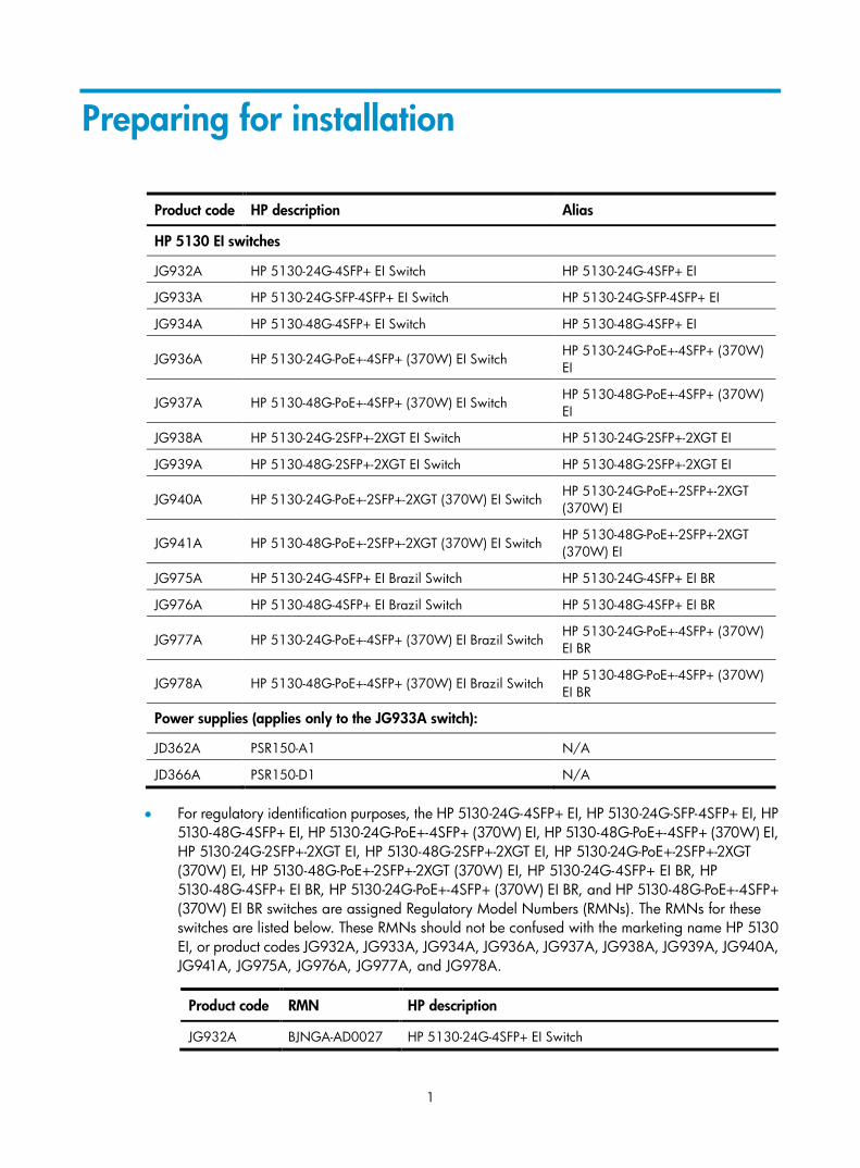
Product code HP description Alias
HP 5130 EI switches
JG932A HP 5130-24G-4SFP+ EI Switch HP 5130-24G-4SFP+ EI
JG933A HP 5130-24G-SFP-4SFP+ EI Switch HP 5130-24G-SFP-4SFP+ EI
JG934A HP 5130-48G-4SFP+ EI Switch HP 5130-48G-4SFP+ EI
JG936A HP 5130-24G-PoE+-4SFP+ (370W) EI Switch HP 5130-24G-PoE+-4SFP+ (370W) EI
JG937A HP 5130-48G-PoE+-4SFP+ (370W) EI Switch HP 5130-48G-PoE+-4SFP+ (370W) EI
JG938A HP 5130-24G-2SFP+-2XGT EI Switch HP 5130-24G-2SFP+-2XGT EI
JG939A HP 5130-48G-2SFP+-2XGT EI Switch HP 5130-48G-2SFP+-2XGT EI
JG940A HP 5130-24G-PoE+-2SFP+-2XGT (370W) EI Switch HP 5130-24G-PoE+-2SFP+-2XGT (370W) EI
JG941A HP 5130-48G-PoE+-2SFP+-2XGT (370W) EI Switch HP 5130-48G-PoE+-2SFP+-2XGT (370W) EI
JG975A HP 5130-24G-4SFP+ EI Brazil Switch HP 5130-24G-4SFP+ EI BR
JG976A HP 5130-48G-4SFP+ EI Brazil Switch HP 5130-48G-4SFP+ EI BR
JG977A HP 5130-24G-PoE+-4SFP+ (370W) EI Brazil Switch HP 5130-24G-PoE+-4SFP+ (370W) EI BR
JG978A HP 5130-48G-PoE+-4SFP+ (370W) EI Brazil Switch HP 5130-48G-PoE+-4SFP+ (370W) EI BR
Power supplies (applies only to the JG933A switch):
JD362A PSR150-A1 N/A
JD366A PSR150-D1 N/A
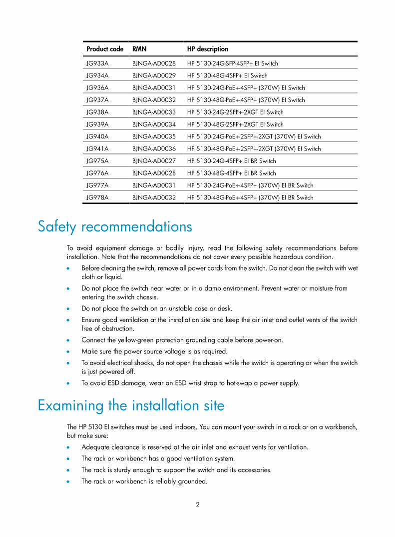
• For regulatory identification purposes, the HP 5130-24G-4SFP+ EI, HP 5130-24G-SFP-4SFP+ EI, HP 5130-48G-4SFP+ EI, HP 5130-24G-PoE+-4SFP+ (370W) EI, HP 5130-48G-PoE+-4SFP+ (370W) EI, HP 5130-24G-2SFP+-2XGT EI, HP 5130-48G-2SFP+-2XGT EI, HP 5130-24G-PoE+-2SFP+-2XGT (370W) EI, HP 5130-48G-PoE+-2SFP+-2XGT (370W) EI, HP 5130-24G-4SFP+ EI BR, HP 5130-48G-4SFP+ EI BR, HP 5130-24G-PoE+-4SFP+ (370W) EI BR, and HP 5130-48G-PoE+-4SFP+ (370W) EI BR switches are assigned Regulatory Model Numbers (RMNs). The RMNs for these switches are listed below. These RMNs should not be confused with the marketing name HP 5130 EI, or product codes JG932A, JG933A, JG934A, JG936A, JG937A, JG938A, JG939A, JG940A, JG941A, JG975A, JG976A, JG977A, and JG978A.
Product code RMN HP description
JG932A BJNGA-AD0027 HP 5130-24G-4SFP+ EI Switch
2
Product code RMN HP description
JG933A BJNGA-AD0028 HP 5130-24G-SFP-4SFP+ EI Switch
JG934A BJNGA-AD0029 HP 5130-48G-4SFP+ EI Switch
JG936A BJNGA-AD0031 HP 5130-24G-PoE+-4SFP+ (370W) EI Switch
JG937A BJNGA-AD0032 HP 5130-48G-PoE+-4SFP+ (370W) EI Switch
JG938A BJNGA-AD0033 HP 5130-24G-2SFP+-2XGT EI Switch
JG939A BJNGA-AD0034 HP 5130-48G-2SFP+-2XGT EI Switch
JG940A BJNGA-AD0035 HP 5130-24G-PoE+-2SFP+-2XGT (370W) EI Switch
JG941A BJNGA-AD0036 HP 5130-48G-PoE+-2SFP+-2XGT (370W) EI Switch
JG975A BJNGA-AD0027 HP 5130-24G-4SFP+ EI BR Switch
JG976A BJNGA-AD0028 HP 5130-48G-4SFP+ EI BR Switch
JG977A BJNGA-AD0031 HP 5130-24G-PoE+-4SFP+ (370W) EI BR Switch
JG978A BJNGA-AD0032 HP 5130-48G-PoE+-4SFP+ (370W) EI BR Switch
Safety recommendations To avoid equipment damage or bodily injury, read the following safety recommendations before installation. Note that the recommendations do not cover every possible hazardous condition.
• Before cleaning the switch, remove all power cords from the switch. Do not clean the switch with wet cloth or liquid.
• Do not place the switch near water or in a damp environment. Prevent water or moisture from entering the switch chassis.
• Do not place the switch on an unstable case or desk.
• Ensure good ventilation at the installation site and keep the air inlet and outlet vents of the switch free of obstruction.
• Connect the yellow-green protection grounding cable before power-on.
• Make sure the power source voltage is as required.
• To avoid electrical shocks, do not open the chassis while the switch is operating or when the switch is just powered off.
• To avoid ESD damage, wear an ESD wrist strap to hot-swap a power supply.
Examining the installation site The HP 5130 EI switches must be used indoors. You can mount your switch in a rack or on a workbench, but make sure:
• Adequate clearance is reserved at the air inlet and exhaust vents for ventilation.
• The rack or workbench has a good ventilation system.
• The rack is sturdy enough to support the switch and its accessories.
• The rack or workbench is reliably grounded.
3
To ensure correct operation and long service life of your switch, install it in an environment that meets the requirements described in the following subsections.
Temperature/humidity Maintain temperature and humidity in the equipment room as described in "Technical specifications."
• Lasting high relative humidity can cause poor insulation, electricity creepage, mechanical property change of materials, and metal corrosion.
• Lasting low relative humidity can cause washer contraction and ESD and bring problems including loose captive screws and circuit failure.
• High temperature can accelerate the aging of insulation materials and significantly lower the reliability and lifespan of the switch.
For the temperature and humidity requirements of different switch models, see "Appendix A Chassis views and technical specifications."
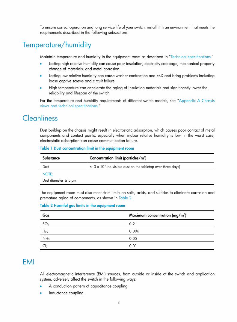
Cleanliness Dust buildup on the chassis might result in electrostatic adsorption, which causes poor contact of metal components and contact points, especially when indoor relative humidity is low. In the worst case, electrostatic adsorption can cause communication failure.
Table 1 Dust concentration limit in the equipment room
Substance Concentration limit (particles/m³)
Dust ≤ 3 x 10⁴ (no visible dust on the tabletop over three days)
NOTE:
Dust diameter ≥ 5 μm
The equipment room must also meet strict limits on salts, acids, and sulfides to eliminate corrosion and premature aging of components, as shown in Table 2.
Table 2 Harmful gas limits in the equipment room
Gas Maximum concentration (mg/m3)
SO2 0.2
H2S 0.006
NH3 0.05
Cl2 0.01
EMI All electromagnetic interference (EMI) sources, from outside or inside of the switch and application system, adversely affect the switch in the following ways:
• A conduction pattern of capacitance coupling.
• Inductance coupling.
4
• Electromagnetic wave radiation.
• Common impedance (including the grounding system) coupling.
To prevent EMI, use the following guidelines:
• If AC power is used, use a single-phase three-wire power receptacle with protective earth (PE) to filter interference from the power grid.
• Keep the switch far away from radio transmitting stations, radar stations, and high-frequency devices to make sure the EMI levels do not exceed the compliant range.
• Use electromagnetic shielding when necessary. For example, use shielded interface cables.
• To prevent signal ports from getting damaged by over-voltage or over-current caused by lightning strikes, only route interface cables indoors.
Laser safety
WARNING!
Do not stare into any fiber port when the switch has power. The laser light emitted from the optical fiber might hurt your eyes.
The HP 5130 EI switches are Class 1 laser devices.
Installation tools • Flat-blade screwdriver
• Phillips screwdriver
• ESD wrist strap
All these installation tools are user supplied.
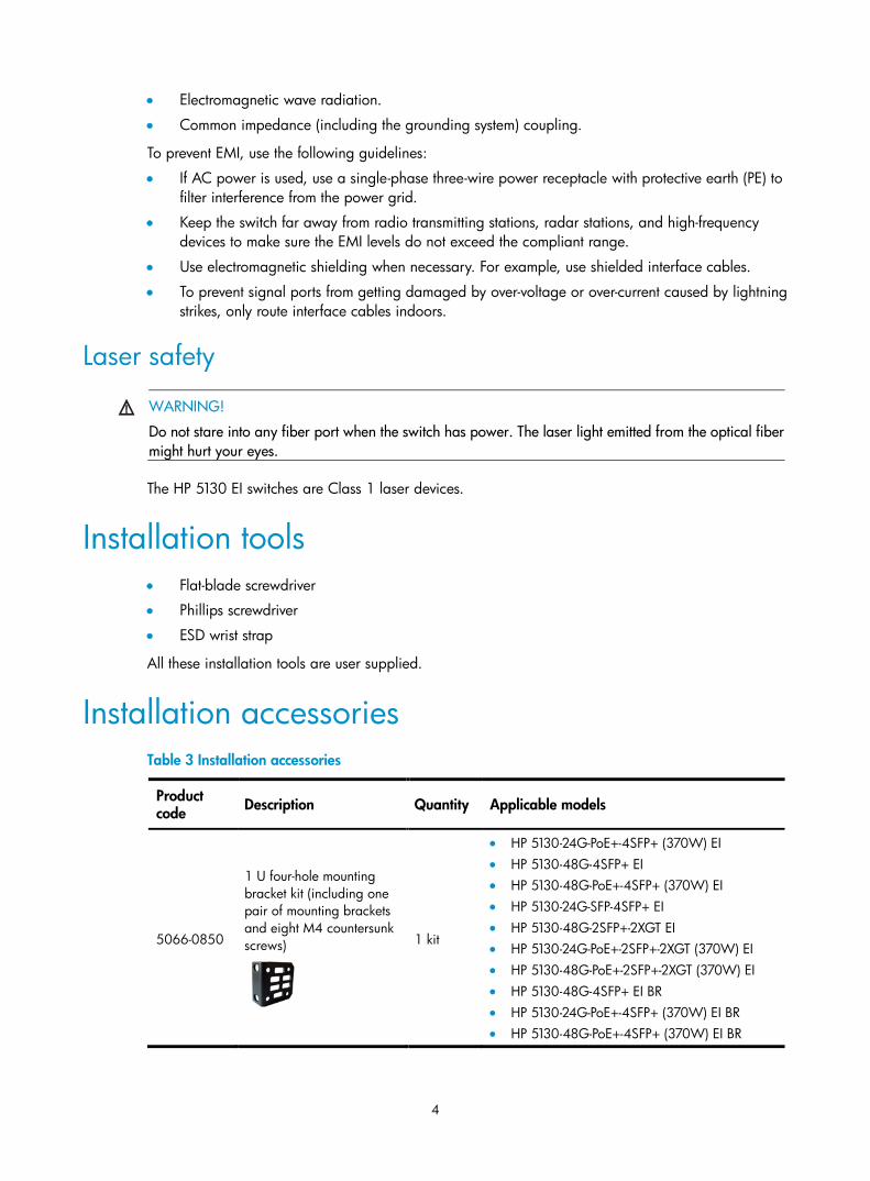
Installation accessories Table 3 Installation accessories
Product code Description Quantity Applicable models
5066-0850
1 U four-hole mounting bracket kit (including one pair of mounting brackets and eight M4 countersunk screws)
1 kit
• HP 5130-24G-PoE+-4SFP+ (370W) EI • HP 5130-48G-4SFP+ EI • HP 5130-48G-PoE+-4SFP+ (370W) EI • HP 5130-24G-SFP-4SFP+ EI • HP 5130-48G-2SFP+-2XGT EI • HP 5130-24G-PoE+-2SFP+-2XGT (370W) EI • HP 5130-48G-PoE+-2SFP+-2XGT (370W) EI • HP 5130-48G-4SFP+ EI BR • HP 5130-24G-PoE+-4SFP+ (370W) EI BR • HP 5130-48G-PoE+-4SFP+ (370W) EI BR
5
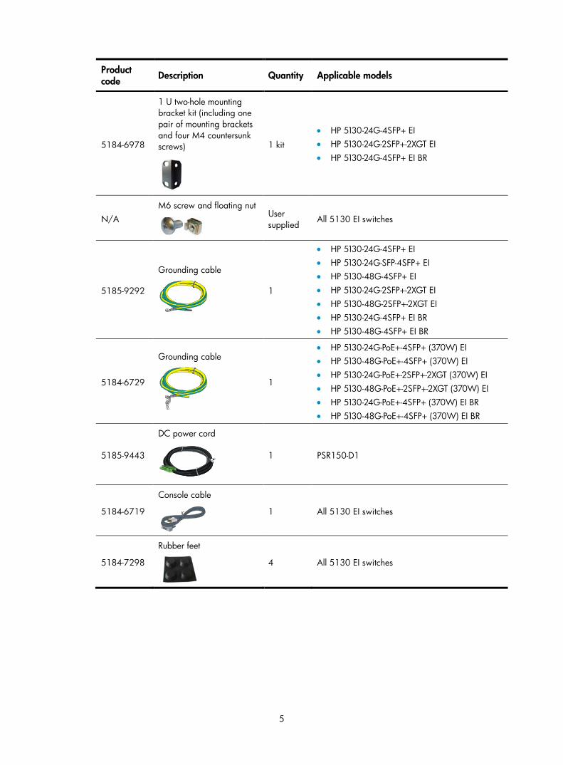
Product code Description Quantity Applicable models
5184-6978
1 U two-hole mounting bracket kit (including one pair of mounting brackets and four M4 countersunk screws)
1 kit
• HP 5130-24G-4SFP+ EI • HP 5130-24G-2SFP+-2XGT EI • HP 5130-24G-4SFP+ EI BR
N/A M6 screw and floating nut
User supplied
All 5130 EI switches
5185-9292
Grounding cable
1
• HP 5130-24G-4SFP+ EI • HP 5130-24G-SFP-4SFP+ EI • HP 5130-48G-4SFP+ EI • HP 5130-24G-2SFP+-2XGT EI • HP 5130-48G-2SFP+-2XGT EI • HP 5130-24G-4SFP+ EI BR • HP 5130-48G-4SFP+ EI BR
5184-6729
Grounding cable
1
• HP 5130-24G-PoE+-4SFP+ (370W) EI • HP 5130-48G-PoE+-4SFP+ (370W) EI • HP 5130-24G-PoE+-2SFP+-2XGT (370W) EI • HP 5130-48G-PoE+-2SFP+-2XGT (370W) EI • HP 5130-24G-PoE+-4SFP+ (370W) EI BR • HP 5130-48G-PoE+-4SFP+ (370W) EI BR
5185-9443
DC power cord
1 PSR150-D1
5184-6719
Console cable
1 All 5130 EI switches
5184-7298
Rubber feet
4 All 5130 EI switches
6
Installing the switch
CAUTION:
Keep the tamper-proof seal on a mounting screw on the chassis cover intact, and if you want to open the chassis, contact HP for permission. Otherwise, HP shall not be liable for any consequence.
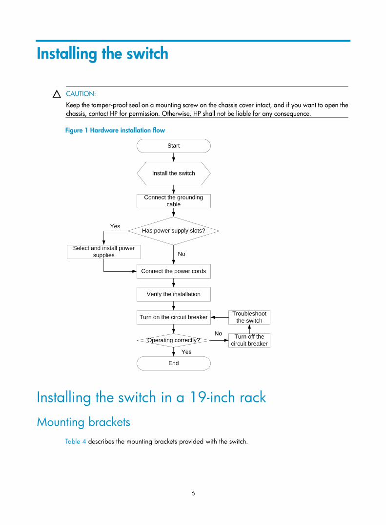
Figure 1 Hardware installation flow
Installing the switch in a 19-inch rack
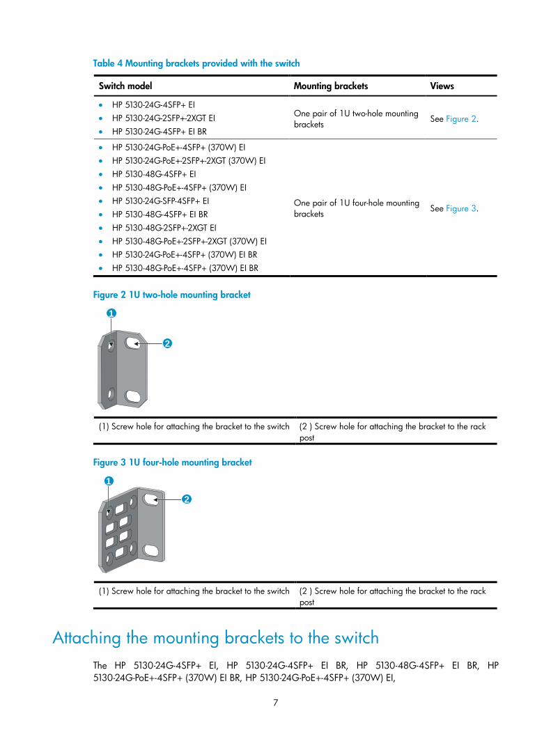
Mounting brackets Table 4 describes the mounting brackets provided with the switch.
Start
Install the switch
Connect the grounding cable
Connect the power cords
Verify the installation
Turn on the circuit breaker
Operating correctly? Turn off the circuit breaker
Troubleshoot the switch
No
End
Has power supply slots?Yes
Select and install power supplies
Yes
No
7
Table 4 Mounting brackets provided with the switch
Switch model Mounting brackets Views
• HP 5130-24G-4SFP+ EI • HP 5130-24G-2SFP+-2XGT EI • HP 5130-24G-4SFP+ EI BR
One pair of 1U two-hole mounting brackets
See Figure 2.
• HP 5130-24G-PoE+-4SFP+ (370W) EI • HP 5130-24G-PoE+-2SFP+-2XGT (370W) EI • HP 5130-48G-4SFP+ EI • HP 5130-48G-PoE+-4SFP+ (370W) EI • HP 5130-24G-SFP-4SFP+ EI • HP 5130-48G-4SFP+ EI BR • HP 5130-48G-2SFP+-2XGT EI • HP 5130-48G-PoE+-2SFP+-2XGT (370W) EI • HP 5130-24G-PoE+-4SFP+ (370W) EI BR • HP 5130-48G-PoE+-4SFP+ (370W) EI BR
One pair of 1U four-hole mounting brackets See Figure 3.
Figure 2 1U two-hole mounting bracket
(1) Screw hole for attaching the bracket to the switch (2 ) Screw hole for attaching the bracket to the rack
post
Figure 3 1U four-hole mounting bracket
(1) Screw hole for attaching the bracket to the switch (2 ) Screw hole for attaching the bracket to the rack
post
Attaching the mounting brackets to the switch The HP 5130-24G-4SFP+ EI, HP 5130-24G-4SFP+ EI BR, HP 5130-48G-4SFP+ EI BR, HP 5130-24G-PoE+-4SFP+ (370W) EI BR, HP 5130-24G-PoE+-4SFP+ (370W) EI,
1
2
1
2
8
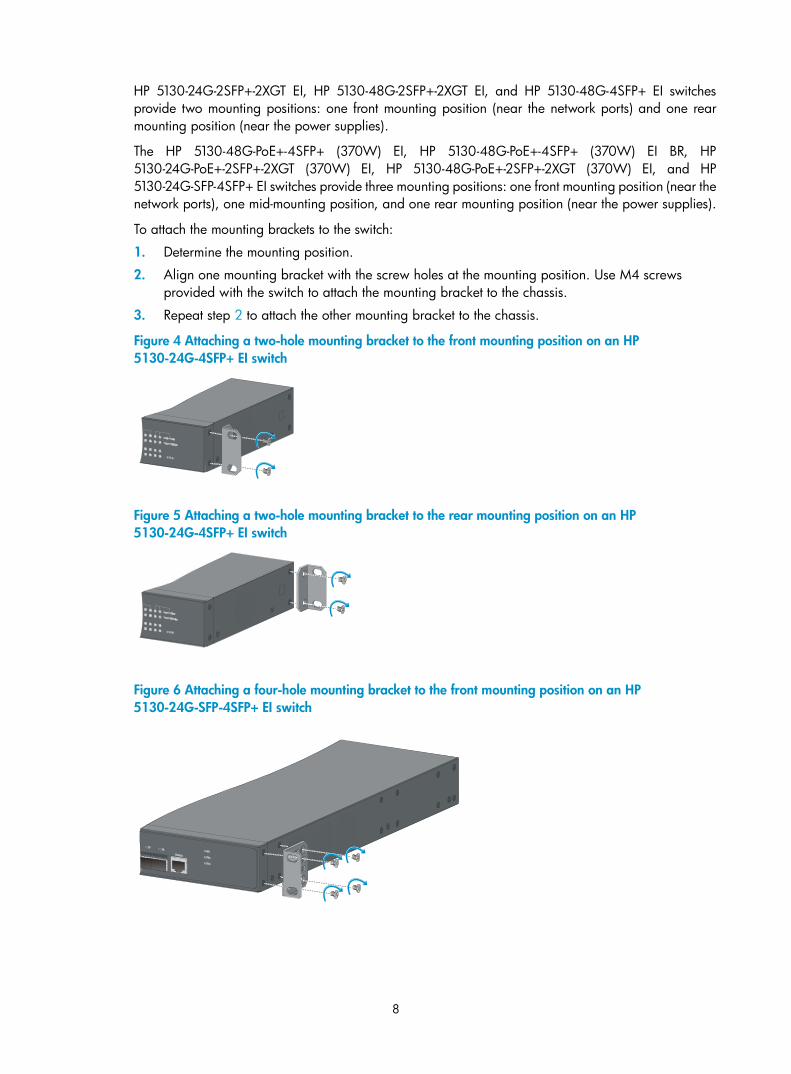
HP 5130-24G-2SFP+-2XGT EI, HP 5130-48G-2SFP+-2XGT EI, and HP 5130-48G-4SFP+ EI switches provide two mounting positions: one front mounting position (near the network ports) and one rear mounting position (near the power supplies).
The HP 5130-48G-PoE+-4SFP+ (370W) EI, HP 5130-48G-PoE+-4SFP+ (370W) EI BR, HP 5130-24G-PoE+-2SFP+-2XGT (370W) EI, HP 5130-48G-PoE+-2SFP+-2XGT (370W) EI, and HP 5130-24G-SFP-4SFP+ EI switches provide three mounting positions: one front mounting position (near the network ports), one mid-mounting position, and one rear mounting position (near the power supplies).
To attach the mounting brackets to the switch:
1. Determine the mounting position.
2. Align one mounting bracket with the screw holes at the mounting position. Use M4 screws provided with the switch to attach the mounting bracket to the chassis.
3. Repeat step 2 to attach the other mounting bracket to the chassis.
Figure 4 Attaching a two-hole mounting bracket to the front mounting position on an HP 5130-24G-4SFP+ EI switch
Figure 5 Attaching a two-hole mounting bracket to the rear mounting position on an HP 5130-24G-4SFP+ EI switch
Figure 6 Attaching a four-hole mounting bracket to the front mounting position on an HP 5130-24G-SFP-4SFP+ EI switch
9
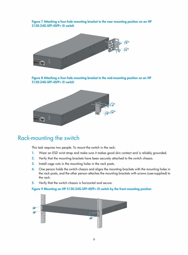
Figure 7 Attaching a four-hole mounting bracket to the rear mounting position on an HP 5130-24G-SFP-4SFP+ EI switch
Figure 8 Attaching a four-hole mounting bracket to the mid-mounting position on an HP 5130-24G-SFP-4SFP+ EI switch
Rack-mounting the switch This task requires two people. To mount the switch in the rack:
1. Wear an ESD wrist strap and make sure it makes good skin contact and is reliably grounded.
2. Verify that the mounting brackets have been securely attached to the switch chassis.
3. Install cage nuts in the mounting holes in the rack posts.
4. One person holds the switch chassis and aligns the mounting brackets with the mounting holes in the rack posts, and the other person attaches the mounting brackets with screws (user-supplied) to the rack.
5. Verify that the switch chassis is horizontal and secure.
Figure 9 Mounting an HP 5130-24G-SFP-4SFP+ EI switch by the front mounting position
10
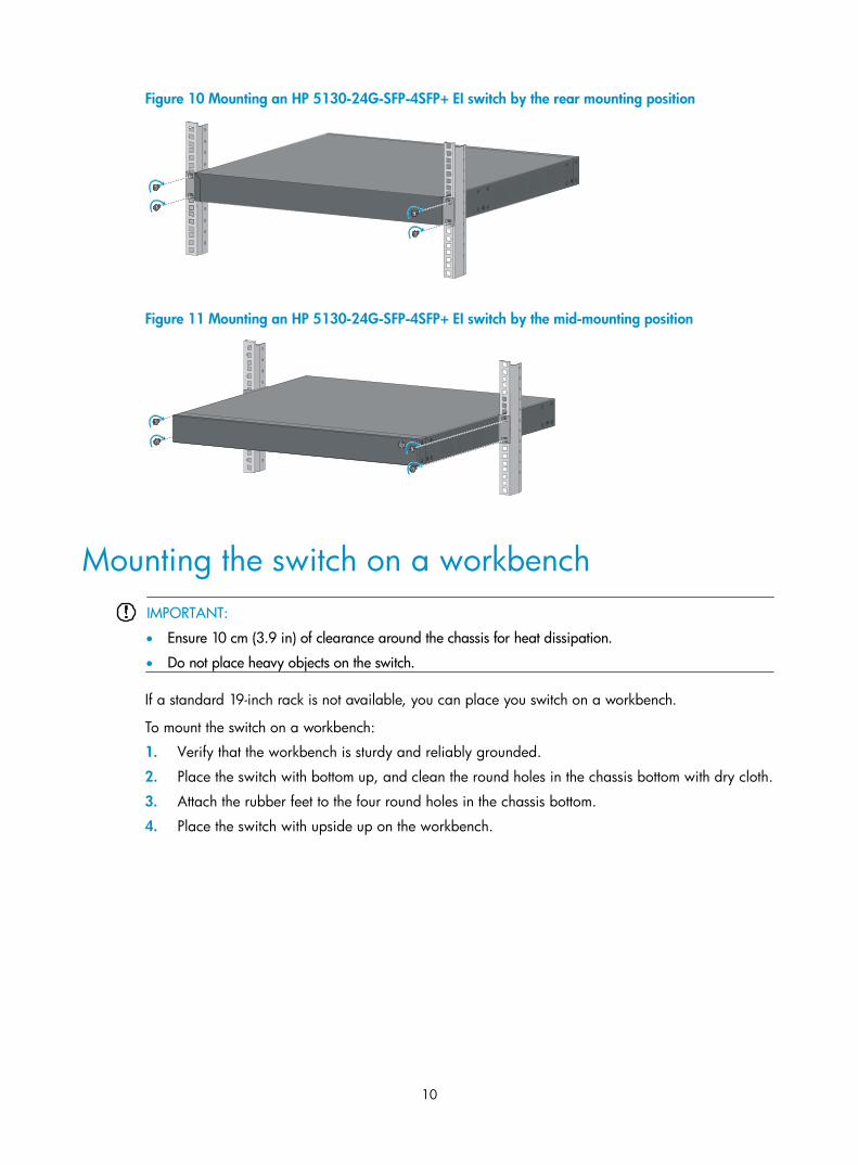
Figure 10 Mounting an HP 5130-24G-SFP-4SFP+ EI switch by the rear mounting position
Figure 11 Mounting an HP 5130-24G-SFP-4SFP+ EI switch by the mid-mounting position
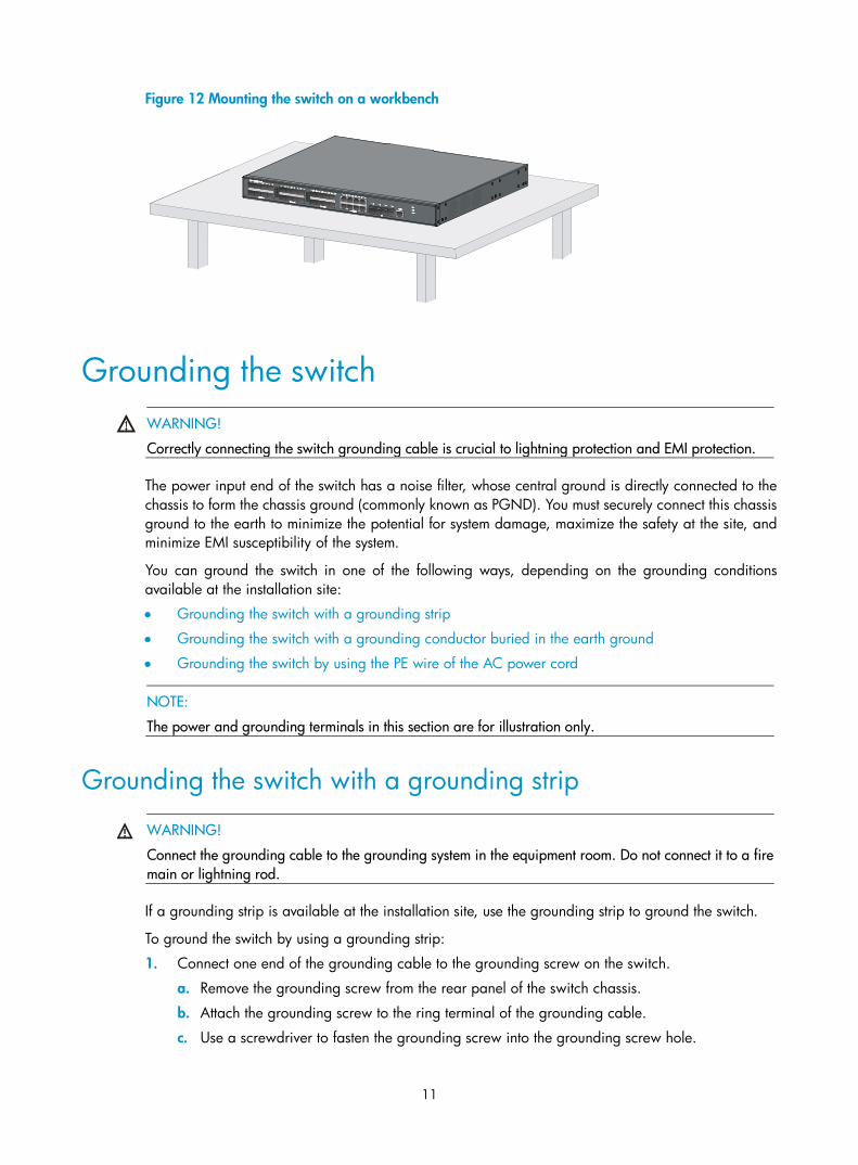
Mounting the switch on a workbench IMPORTANT:
• Ensure 10 cm (3.9 in) of clearance around the chassis for heat dissipation.
• Do not place heavy objects on the switch.
If a standard 19-inch rack is not available, you can place you switch on a workbench.
To mount the switch on a workbench:
1. Verify that the workbench is sturdy and reliably grounded.
2. Place the switch with bottom up, and clean the round holes in the chassis bottom with dry cloth.
3. Attach the rubber feet to the four round holes in the chassis bottom.
4. Place the switch with upside up on the workbench.
11
Figure 12 Mounting the switch on a workbench
Grounding the switch WARNING!
Correctly connecting the switch grounding cable is crucial to lightning protection and EMI protection.
The power input end of the switch has a noise filter, whose central ground is directly connected to the chassis to form the chassis ground (commonly known as PGND). You must securely connect this chassis ground to the earth to minimize the potential for system damage, maximize the safety at the site, and minimize EMI susceptibility of the system.
You can ground the switch in one of the following ways, depending on the grounding conditions available at the installation site:
• Grounding the switch with a grounding strip
• Grounding the switch with a grounding conductor buried in the earth ground
• Grounding the switch by using the PE wire of the AC power cord
NOTE:
The power and grounding terminals in this section are for illustration only.
Grounding the switch with a grounding strip
WARNING!
Connect the grounding cable to the grounding system in the equipment room. Do not connect it to a fire main or lightning rod.
If a grounding strip is available at the installation site, use the grounding strip to ground the switch.
To ground the switch by using a grounding strip:
1. Connect one end of the grounding cable to the grounding screw on the switch.
a. Remove the grounding screw from the rear panel of the switch chassis.
b. Attach the grounding screw to the ring terminal of the grounding cable.
c. Use a screwdriver to fasten the grounding screw into the grounding screw hole.
12
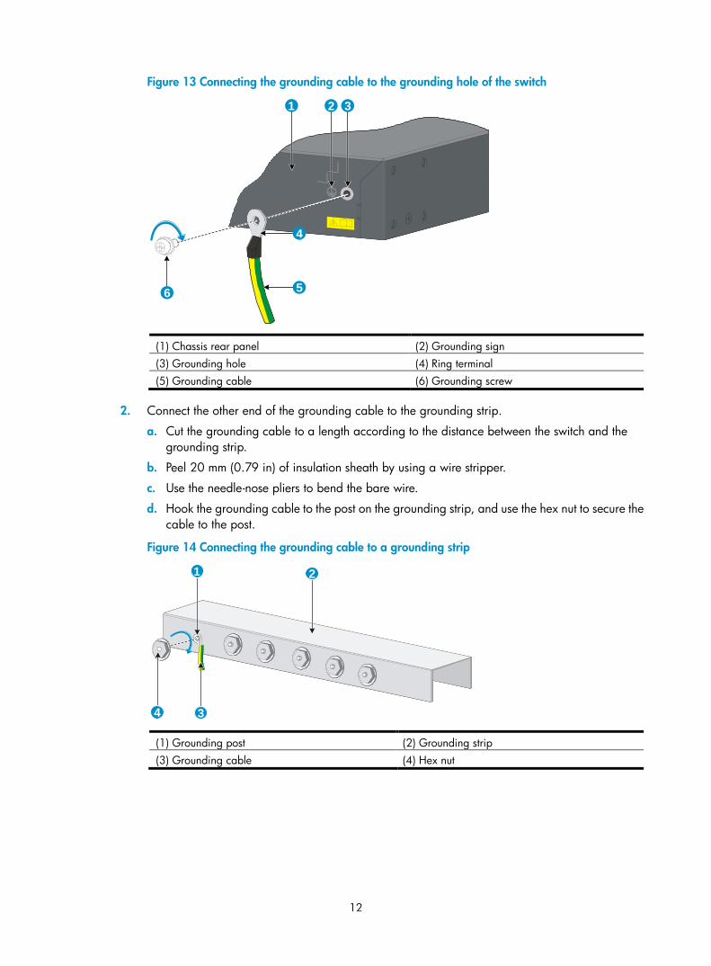
Figure 13 Connecting the grounding cable to the grounding hole of the switch
(1) Chassis rear panel (2) Grounding sign (3) Grounding hole (4) Ring terminal (5) Grounding cable (6) Grounding screw
2. Connect the other end of the grounding cable to the grounding strip.
a. Cut the grounding cable to a length according to the distance between the switch and the grounding strip.
b. Peel 20 mm (0.79 in) of insulation sheath by using a wire stripper.
c. Use the needle-nose pliers to bend the bare wire.
d. Hook the grounding cable to the post on the grounding strip, and use the hex nut to secure the cable to the post.
Figure 14 Connecting the grounding cable to a grounding strip
(1) Grounding post (2) Grounding strip (3) Grounding cable (4) Hex nut
1 2 3
4
56
1 2
34
13
Grounding the switch with a grounding conductor buried in the earth ground
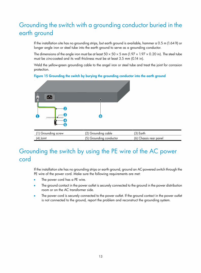
If the installation site has no grounding strips, but earth ground is available, hammer a 0.5 m (1.64 ft) or longer angle iron or steel tube into the earth ground to serve as a grounding conductor.
The dimensions of the angle iron must be at least 50 × 50 × 5 mm (1.97 × 1.97 × 0.20 in). The steel tube must be zinc-coated and its wall thickness must be at least 3.5 mm (0.14 in).
Weld the yellow-green grounding cable to the angel iron or steel tube and treat the joint for corrosion protection.
Figure 15 Grounding the switch by burying the grounding conductor into the earth ground
(1) Grounding screw (2) Grounding cable (3) Earth (4) Joint (5) Grounding conductor (6) Chassis rear panel
Grounding the switch by using the PE wire of the AC power cord
If the installation site has no grounding strips or earth ground, ground an AC-powered switch through the PE wire of the power cord. Make sure the following requirements are met:
• The power cord has a PE wire.
• The ground contact in the power outlet is securely connected to the ground in the power distribution room or on the AC transformer side.
• The power cord is securely connected to the power outlet. If the ground contact in the power outlet is not connected to the ground, report the problem and reconstruct the grounding system.
1
2
345
6
14
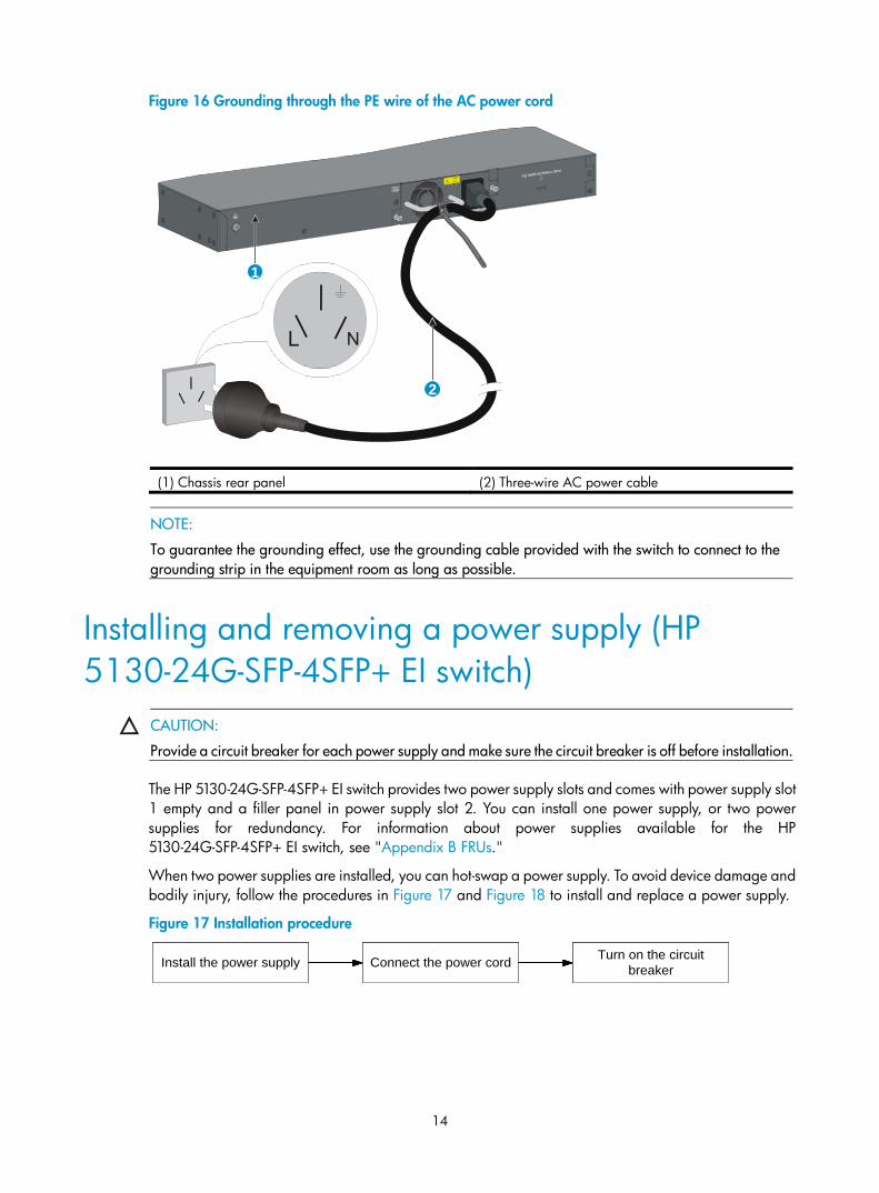
Figure 16 Grounding through the PE wire of the AC power cord
(1) Chassis rear panel (2) Three-wire AC power cable
NOTE:
To guarantee the grounding effect, use the grounding cable provided with the switch to connect to the grounding strip in the equipment room as long as possible.
Installing and removing a power supply (HP 5130-24G-SFP-4SFP+ EI switch)
CAUTION:
Provide a circuit breaker for each power supply and make sure the circuit breaker is off before installation.
The HP 5130-24G-SFP-4SFP+ EI switch provides two power supply slots and comes with power supply slot 1 empty and a filler panel in power supply slot 2. You can install one power supply, or two power supplies for redundancy. For information about power supplies available for the HP 5130-24G-SFP-4SFP+ EI switch, see "Appendix B FRUs."
When two power supplies are installed, you can hot-swap a power supply. To avoid device damage and bodily injury, follow the procedures in Figure 17 and Figure 18 to install and replace a power supply.
Figure 17 Installation procedure
2
1
安装电源模块 连接电源线 给电源模块加电安装电源模块 连接电源线 给电源模块加电安装电源模块 连接电源线 给电源模块加电Install the power supply Connect the power cord Turn on the circuit breaker
15
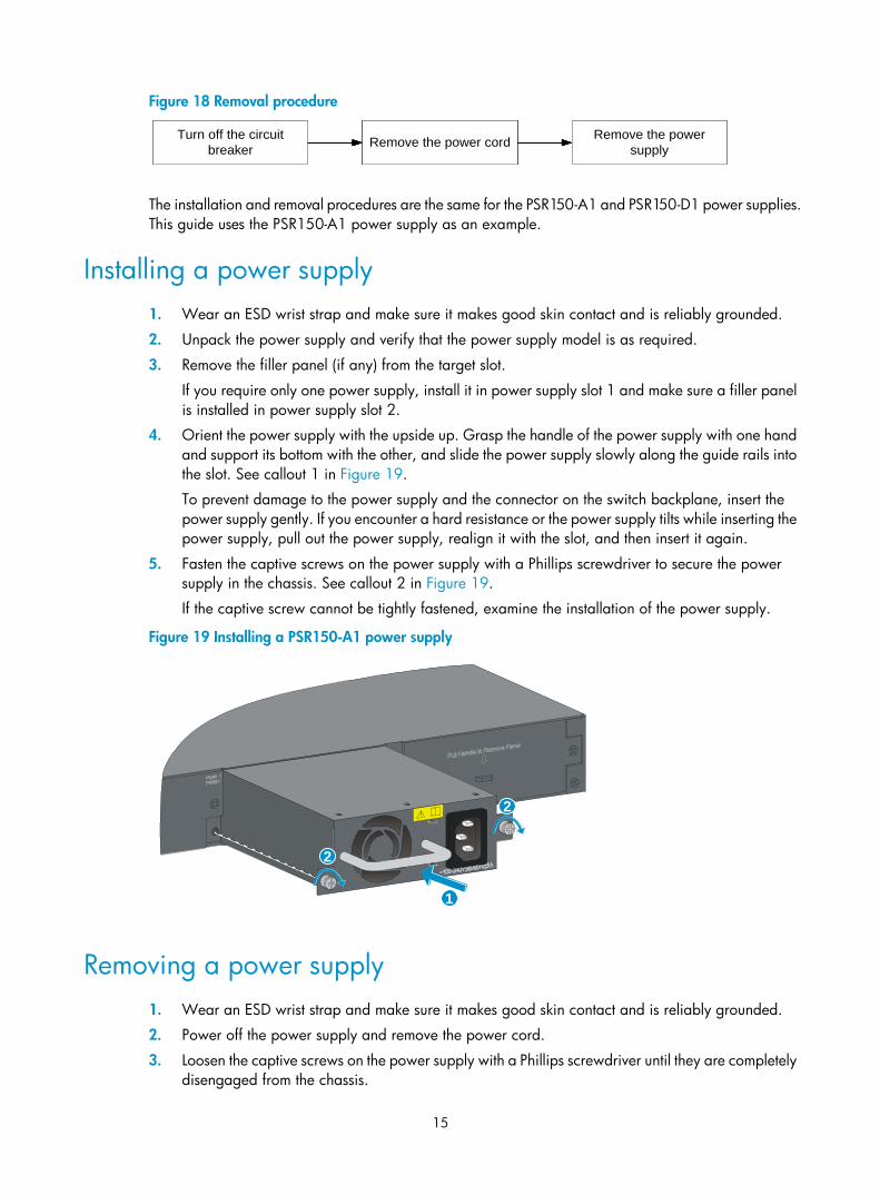
Figure 18 Removal procedure
The installation and removal procedures are the same for the PSR150-A1 and PSR150-D1 power supplies. This guide uses the PSR150-A1 power supply as an example.
Installing a power supply 1. Wear an ESD wrist strap and make sure it makes good skin contact and is reliably grounded.
2. Unpack the power supply and verify that the power supply model is as required.
3. Remove the filler panel (if any) from the target slot.
If you require only one power supply, install it in power supply slot 1 and make sure a filler panel is installed in power supply slot 2.
4. Orient the power supply with the upside up. Grasp the handle of the power supply with one hand and support its bottom with the other, and slide the power supply slowly along the guide rails into the slot. See callout 1 in Figure 19.
To prevent damage to the power supply and the connector on the switch backplane, insert the power supply gently. If you encounter a hard resistance or the power supply tilts while inserting the power supply, pull out the power supply, realign it with the slot, and then insert it again.
5. Fasten the captive screws on the power supply with a Phillips screwdriver to secure the power supply in the chassis. See callout 2 in Figure 19.
If the captive screw cannot be tightly fastened, examine the installation of the power supply.
Figure 19 Installing a PSR150-A1 power supply
Removing a power supply 1. Wear an ESD wrist strap and make sure it makes good skin contact and is reliably grounded.
2. Power off the power supply and remove the power cord.
3. Loosen the captive screws on the power supply with a Phillips screwdriver until they are completely disengaged from the chassis.
将电源模块断电 拆卸电源线 拆卸电源模块将电源模块断电 拆卸电源线 拆卸电源模块将电源模块断电 拆卸电源线 拆卸电源模块Turn off the circuit
breaker Remove the power cord Remove the power supply
1
2
2
16
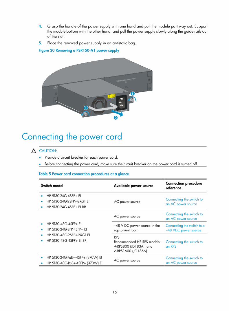
4. Grasp the handle of the power supply with one hand and pull the module part way out. Support the module bottom with the other hand, and pull the power supply slowly along the guide rails out of the slot.
5. Place the removed power supply in an antistatic bag.
Figure 20 Removing a PSR150-A1 power supply
Connecting the power cord CAUTION:
• Provide a circuit breaker for each power cord.
• Before connecting the power cord, make sure the circuit breaker on the power cord is turned off.
Table 5 Power cord connection procedures at a glance
Switch model Available power source Connection procedure reference
• HP 5130-24G-4SFP+ EI • HP 5130-24G-2SFP+-2XGT EI • HP 5130-24G-4SFP+ EI BR
AC power source Connecting the switch to an AC power source
• HP 5130-48G-4SFP+ EI • HP 5130-24G-SFP-4SFP+ EI • HP 5130-48G-2SFP+-2XGT EI • HP 5130-48G-4SFP+ EI BR
AC power source Connecting the switch to an AC power source
–48 V DC power source in the equipment room
Connecting the switch to a –48 VDC power source
RPS Recommended HP RPS models: A-RPS800 (JD183A ) and A-RPS1600 (JG136A)
Connecting the switch to an RPS
• HP 5130-24G-PoE+-4SFP+ (370W) EI • HP 5130-48G-PoE+-4SFP+ (370W) EI
AC power source Connecting the switch to an AC power source
1
2
1
17
Switch model Available power source Connection procedure reference
HP A-RPS1600 Connecting the switch to an RPS
The HP 5130-24G-SFP-4SFP+ EI switch provides two power supply slots. The PSR150-A1 and PSR150-D1 power supplies are available for the HP 5130-24G-SFP-4SFP+ EI switch. The PSR150-A1 power supply supports AC power input. The PSR150-D1 power supply supports –48 V DC power input and RPS power input.
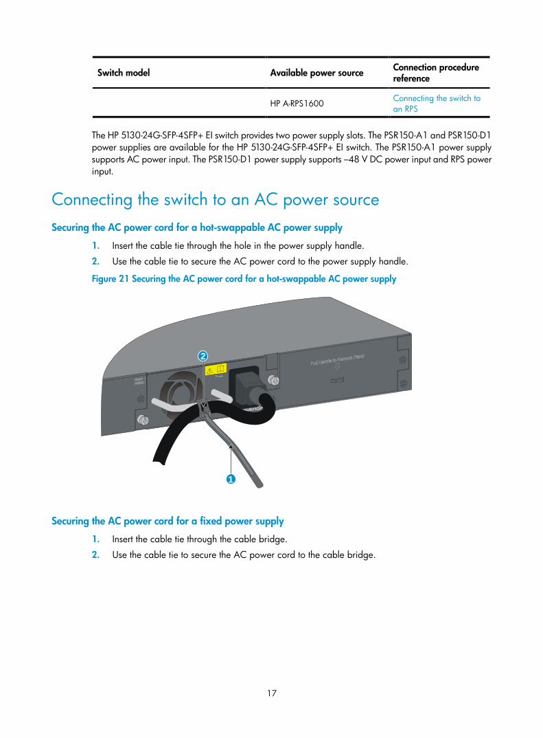
Connecting the switch to an AC power source Securing the AC power cord for a hot-swappable AC power supply
1. Insert the cable tie through the hole in the power supply handle.
2. Use the cable tie to secure the AC power cord to the power supply handle.
Figure 21 Securing the AC power cord for a hot-swappable AC power supply
Securing the AC power cord for a fixed power supply
1. Insert the cable tie through the cable bridge.
2. Use the cable tie to secure the AC power cord to the cable bridge.
1
2
18
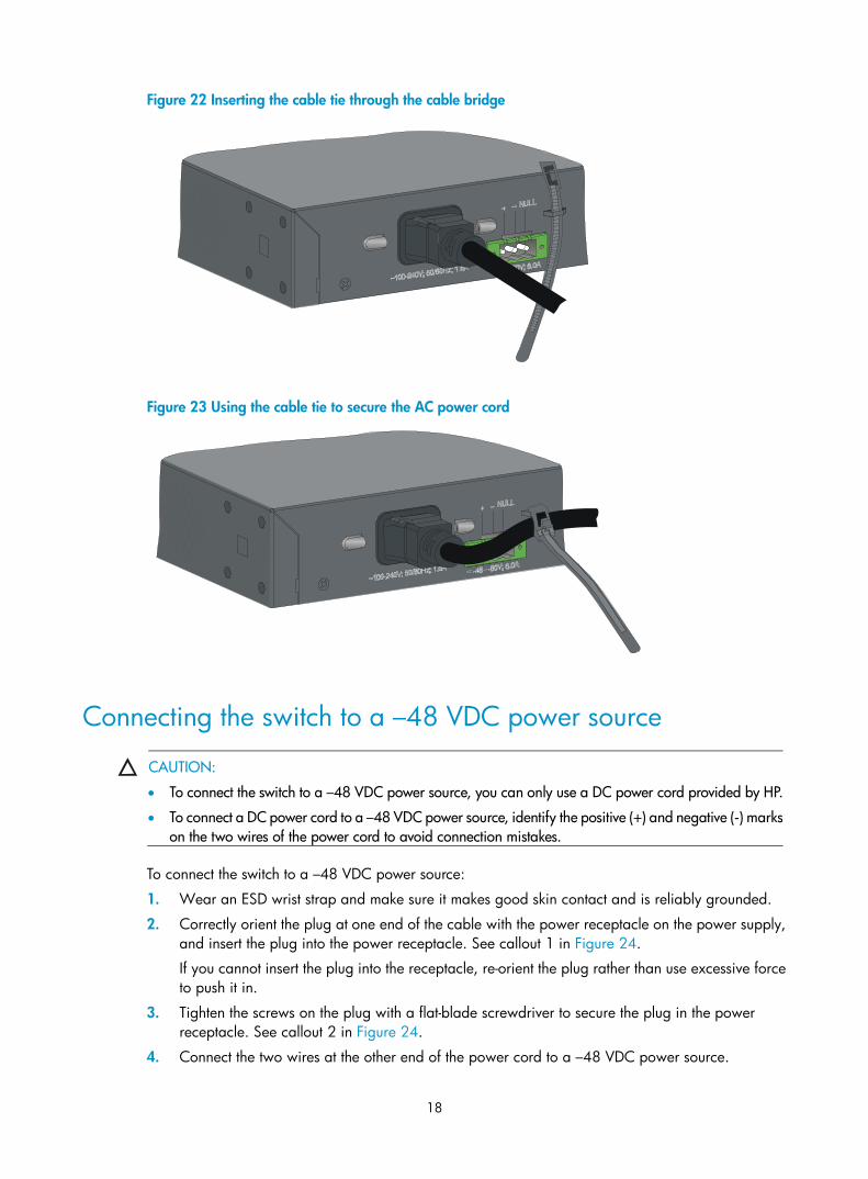
Figure 22 Inserting the cable tie through the cable bridge
Figure 23 Using the cable tie to secure the AC power cord
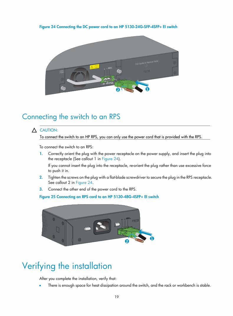
Connecting the switch to a –48 VDC power source
CAUTION:
• To connect the switch to a –48 VDC power source, you can only use a DC power cord provided by HP.
• To connect a DC power cord to a –48 VDC power source, identify the positive (+) and negative (-) marks on the two wires of the power cord to avoid connection mistakes.
To connect the switch to a –48 VDC power source:
1. Wear an ESD wrist strap and make sure it makes good skin contact and is reliably grounded.
2. Correctly orient the plug at one end of the cable with the power receptacle on the power supply, and insert the plug into the power receptacle. See callout 1 in Figure 24.
If you cannot insert the plug into the receptacle, re-orient the plug rather than use excessive force to push it in.
3. Tighten the screws on the plug with a flat-blade screwdriver to secure the plug in the power receptacle. See callout 2 in Figure 24.
4. Connect the two wires at the other end of the power cord to a –48 VDC power source.
19
Figure 24 Connecting the DC power cord to an HP 5130-24G-SFP-4SFP+ EI switch
Connecting the switch to an RPS
CAUTION:
To connect the switch to an HP RPS, you can only use the power cord that is provided with the RPS.
To connect the switch to an RPS:
1. Correctly orient the plug with the power receptacle on the power supply, and insert the plug into the receptacle (See callout 1 in Figure 24).
If you cannot insert the plug into the receptacle, re-orient the plug rather than use excessive force to push it in.
2. Tighten the screws on the plug with a flat-blade screwdriver to secure the plug in the RPS receptacle. See callout 2 in Figure 24.
3. Connect the other end of the power cord to the RPS.
Figure 25 Connecting an RPS cord to an HP 5130-48G-4SFP+ EI switch
Verifying the installation After you complete the installation, verify that:
• There is enough space for heat dissipation around the switch, and the rack or workbench is stable.
12
12

20
• The grounding cable is securely connected.
• The correct power source is used.
• The power cords are correctly connected.
• All the interface cables are cabled indoors. If any cable is routed outdoors, verify that the socket strip with lightning protection and lightning arresters for network ports have been correctly connected.
21
Accessing the switch for the first time
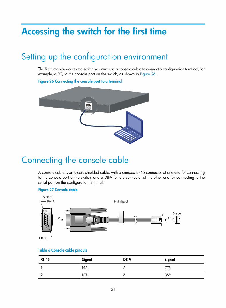
Setting up the configuration environment The first time you access the switch you must use a console cable to connect a configuration terminal, for example, a PC, to the console port on the switch, as shown in Figure 26.
Figure 26 Connecting the console port to a terminal
Connecting the console cable A console cable is an 8-core shielded cable, with a crimped RJ-45 connector at one end for connecting to the console port of the switch, and a DB-9 female connector at the other end for connecting to the serial port on the configuration terminal.
Figure 27 Console cable
Table 6 Console cable pinouts
RJ-45 Signal DB-9 Signal
1 RTS 8 CTS
2 DTR 6 DSR
Main label
1
8 B sideB
Pin 9
Pin 1
A side
A
22
RJ-45 Signal DB-9 Signal
3 TXD 2 RXD
4 SG 5 SG
5 SG 5 SG
6 RXD 3 TXD
7 DSR 4 DTR
8 CTS 7 RTS
To connect a terminal (for example, a PC) to the switch:
1. Plug the DB-9 female connector of the console cable to the serial port of the PC.
2. Connect the RJ-45 connector to the console port of the switch.
NOTE:
• Identify the mark on the console port and make sure you are connecting to the correct port.
• The serial ports on PCs do not support hot swapping. To connect a PC to an operating switch, first connect the PC end. To disconnect a PC from an operating switch, first disconnect the switch end.
Setting terminal parameters To configure and manage the switch through the console port, you must run a terminal emulator program, HyperTerminal or PuTTY, on your configuration terminal. For more information about the terminal emulator programs, see the user guides for these programs.
The following are the required terminal settings:
• Bits per second—9,600.
• Data bits—8.
• Stop bits—1.
• Parity—None.
• Flow control—None.
Powering on the switch Before powering on the switch, verify that the following conditions are met:
• The power cord is correctly connected.
• The input power voltage meets the requirement of the switch.
• The console cable is correctly connected.
• The configuration terminal (a PC, for example) has started, and its serial port settings are consistent with the console port settings on the switch.
Power on the switch. During the startup process, you can access Boot ROM menus to perform tasks such as software upgrade and file management. The Boot ROM interface and menu options differ with software versions. For more information about Boot ROM menu options, see the software-matching release notes for the device.

23
After the startup completes, you can access the CLI to configure the switch.
For more information about the configuration commands and CLI, see HP 5130 EI Switch Series Configuration Guides and HP 5130 EI Switch Series Command References.
24
Setting up an IRF fabric
You can use HP IRF technology to connect and virtualize HP 5130 EI switches into a large virtual switch called an "IRF fabric" for flattened network topology, and high availability, scalability, and manageability.
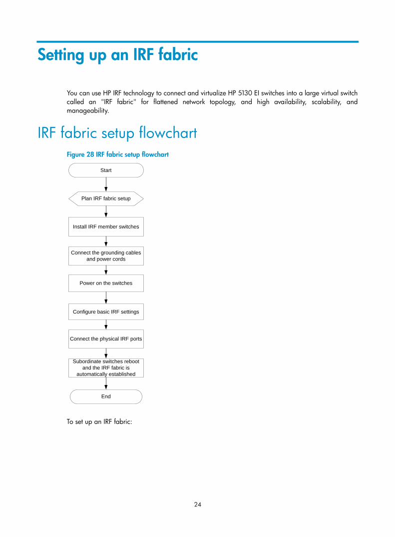
IRF fabric setup flowchart Figure 28 IRF fabric setup flowchart
To set up an IRF fabric:
Start
Plan IRF fabric setup
Install IRF member switches
Connect the grounding cables and power cords
Power on the switches
Configure basic IRF settings
Connect the physical IRF ports
Subordinate switches reboot and the IRF fabric is
automatically established
End
25
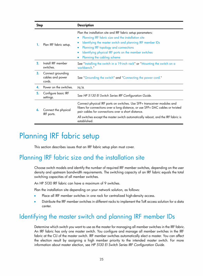
Step Description
1. Plan IRF fabric setup.
Plan the installation site and IRF fabric setup parameters: • Planning IRF fabric size and the installation site • Identifying the master switch and planning IRF member IDs • Planning IRF topology and connections • Identifying physical IRF ports on the member switches • Planning the cabling scheme
2. Install IRF member switches.
See "Installing the switch in a 19-inch rack" or "Mounting the switch on a workbench."
3. Connect grounding cables and power cords.
See "Grounding the switch" and "Connecting the power cord."
4. Power on the switches. N/A
5. Configure basic IRF settings. See HP 5130 EI Switch Series IRF Configuration Guide.
6. Connect the physical IRF ports.
Connect physical IRF ports on switches. Use SFP+ transceiver modules and fibers for connections over a long distance, or use SFP+ DAC cables or twisted pair cables for connections over a short distance.
All switches except the master switch automatically reboot, and the IRF fabric is established.
Planning IRF fabric setup This section describes issues that an IRF fabric setup plan must cover.
Planning IRF fabric size and the installation site Choose switch models and identify the number of required IRF member switches, depending on the user density and upstream bandwidth requirements. The switching capacity of an IRF fabric equals the total switching capacities of all member switches.
An HP 5130 IRF fabric can have a maximum of 9 switches.
Plan the installation site depending on your network solution, as follows:
• Place all IRF member switches in one rack for centralized high-density access.
• Distribute the IRF member switches in different racks to implement the ToR access solution for a data center.
Identifying the master switch and planning IRF member IDs Determine which switch you want to use as the master for managing all member switches in the IRF fabric. An IRF fabric has only one master switch. You configure and manage all member switches in the IRF fabric at the CLI of the master switch. IRF member switches automatically elect a master. You can affect the election result by assigning a high member priority to the intended master switch. For more information about master election, see HP 5130 EI Switch Series IRF Configuration Guide.
26
Prepare an IRF member ID assignment scheme. An IRF fabric uses member IDs to uniquely identify and manage its members, and you must assign each IRF member switch a unique member ID.
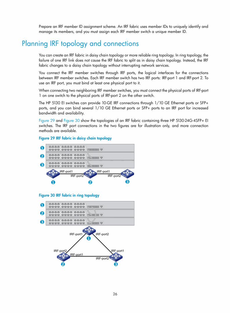
Planning IRF topology and connections You can create an IRF fabric in daisy chain topology or more reliable ring topology. In ring topology, the failure of one IRF link does not cause the IRF fabric to split as in daisy chain topology. Instead, the IRF fabric changes to a daisy chain topology without interrupting network services.
You connect the IRF member switches through IRF ports, the logical interfaces for the connections between IRF member switches. Each IRF member switch has two IRF ports: IRF-port 1 and IRF-port 2. To use an IRF port, you must bind at least one physical port to it.
When connecting two neighboring IRF member switches, you must connect the physical ports of IRF-port 1 on one switch to the physical ports of IRF-port 2 on the other switch.
The HP 5130 EI switches can provide 10-GE IRF connections through 1/10 GE Ethernet ports or SFP+ ports, and you can bind several 1/10 GE Ethernet ports or SFP+ ports to an IRF port for increased bandwidth and availability.
Figure 29 and Figure 30 show the topologies of an IRF fabric containing three HP 5130-24G-4SFP+ EI switches. The IRF port connections in the two figures are for illustration only, and more connection methods are available.
Figure 29 IRF fabric in daisy chain topology
Figure 30 IRF fabric in ring topology
1
2
3IRF-port1
IRF-port2IRF-port1
IRF-port2
1 2 3
IRF-port1
IRF-port2IRF-port1
IRF-port1
IRF-port2
IRF-port2
1
2
3
1
2 3
27
Identifying physical IRF ports on the member switches Identify the physical IRF ports on the member switches according to your topology and connection scheme.
Planning the cabling scheme Use twisted pair cables, SFP+ DAC cables, or SFP+ transceiver modules and fibers to connect the IRF member switches. If the IRF member switches are far away from one another, choose the SFP+ transceiver modules with optical fibers. If the IRF member switches are all in one equipment room, choose twisted pair cables or SFP+ DAC cables.
HP recommends that you use ring topology to connect the switches. The following describes cabling schemes in ring topology.
Connecting the IRF member switches in one rack
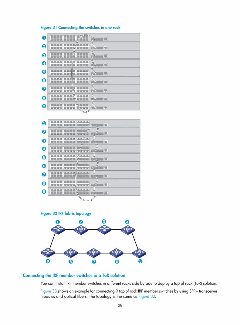
Use SFP+ DAC cables to connect the IRF member switches (9 switches in this example) in a rack as shown in Figure 31. The switches in the ring topology (see Figure 32) are in the same order as connected in the rack.
28
Figure 31 Connecting the switches in one rack
Figure 32 IRF fabric topology
Connecting the IRF member switches in a ToR solution
You can install IRF member switches in different racks side by side to deploy a top of rack (ToR) solution.
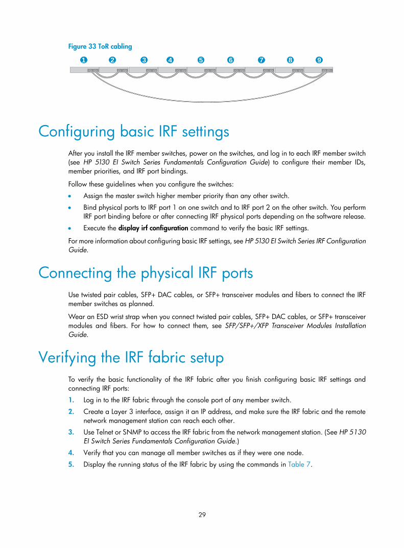
Figure 33 shows an example for connecting 9 top of rack IRF member switches by using SFP+ transceiver modules and optical fibers. The topology is the same as Figure 32.
1
2
3
4
5
6
7
8
9
1
2
3
4
5
6
7
8
9
1 2 3 4
56789
29
Figure 33 ToR cabling
Configuring basic IRF settings After you install the IRF member switches, power on the switches, and log in to each IRF member switch (see HP 5130 EI Switch Series Fundamentals Configuration Guide) to configure their member IDs, member priorities, and IRF port bindings.
Follow these guidelines when you configure the switches:
• Assign the master switch higher member priority than any other switch.
• Bind physical ports to IRF port 1 on one switch and to IRF port 2 on the other switch. You perform IRF port binding before or after connecting IRF physical ports depending on the software release.
• Execute the display irf configuration command to verify the basic IRF settings.
For more information about configuring basic IRF settings, see HP 5130 EI Switch Series IRF Configuration Guide.
Connecting the physical IRF ports Use twisted pair cables, SFP+ DAC cables, or SFP+ transceiver modules and fibers to connect the IRF member switches as planned.
Wear an ESD wrist strap when you connect twisted pair cables, SFP+ DAC cables, or SFP+ transceiver modules and fibers. For how to connect them, see SFP/SFP+/XFP Transceiver Modules Installation Guide.
Verifying the IRF fabric setup To verify the basic functionality of the IRF fabric after you finish configuring basic IRF settings and connecting IRF ports:
1. Log in to the IRF fabric through the console port of any member switch.
2. Create a Layer 3 interface, assign it an IP address, and make sure the IRF fabric and the remote network management station can reach each other.
3. Use Telnet or SNMP to access the IRF fabric from the network management station. (See HP 5130 EI Switch Series Fundamentals Configuration Guide.)
4. Verify that you can manage all member switches as if they were one node.
5. Display the running status of the IRF fabric by using the commands in Table 7.
1 2 3 4 5 6 7 8 9

30
Table 7 Displaying and maintaining IRF configuration and running status
Task Command
Display information about the IRF fabric. display irf
Display all members' IRF configurations that take effect at a reboot.
display irf configuration
Display IRF fabric topology information. display irf topology
NOTE:
To avoid IP address collision and network problems, configure at least one multi-active detection (MAD) mechanism to detect the presence of multiple identical IRF fabrics and handle collisions. For more information about MAD detection, see HP 5130 EI Switch Series IRF Configuration Guide.
31
Maintenance and troubleshooting
Power supply failure
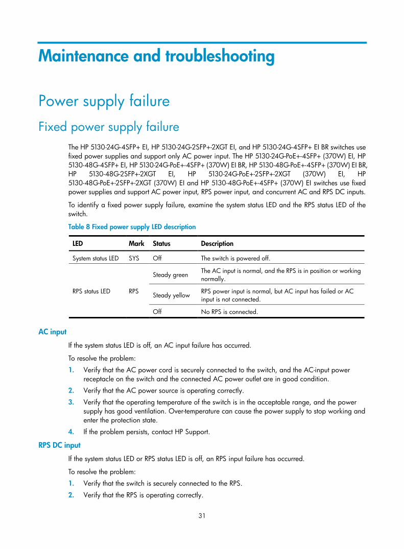
Fixed power supply failure The HP 5130-24G-4SFP+ EI, HP 5130-24G-2SFP+-2XGT EI, and HP 5130-24G-4SFP+ EI BR switches use fixed power supplies and support only AC power input. The HP 5130-24G-PoE+-4SFP+ (370W) EI, HP 5130-48G-4SFP+ EI, HP 5130-24G-PoE+-4SFP+ (370W) EI BR, HP 5130-48G-PoE+-4SFP+ (370W) EI BR, HP 5130-48G-2SFP+-2XGT EI, HP 5130-24G-PoE+-2SFP+-2XGT (370W) EI, HP 5130-48G-PoE+-2SFP+-2XGT (370W) EI and HP 5130-48G-PoE+-4SFP+ (370W) EI switches use fixed power supplies and support AC power input, RPS power input, and concurrent AC and RPS DC inputs.
To identify a fixed power supply failure, examine the system status LED and the RPS status LED of the switch.
Table 8 Fixed power supply LED description
LED Mark Status Description
System status LED SYS Off The switch is powered off.
RPS status LED RPS
Steady green The AC input is normal, and the RPS is in position or working normally.
Steady yellow RPS power input is normal, but AC input has failed or AC input is not connected.
Off No RPS is connected.
AC input
If the system status LED is off, an AC input failure has occurred.
To resolve the problem:
1. Verify that the AC power cord is securely connected to the switch, and the AC-input power receptacle on the switch and the connected AC power outlet are in good condition.
2. Verify that the AC power source is operating correctly.
3. Verify that the operating temperature of the switch is in the acceptable range, and the power supply has good ventilation. Over-temperature can cause the power supply to stop working and enter the protection state.
4. If the problem persists, contact HP Support.
RPS DC input
If the system status LED or RPS status LED is off, an RPS input failure has occurred.
To resolve the problem:
1. Verify that the switch is securely connected to the RPS.
2. Verify that the RPS is operating correctly.
32
3. Verify that the operating temperature of the switch is in the acceptable range, and the power supply has good ventilation. Over-temperature can cause the power supply to stop working and enter the protection state.
4. If the problem persists, contact HP Support.
Concurrent RPS and AC inputs
• If the system status LED is off, the AC power supply and the RPS both have an input failure.
To resolve the problem:
a. Verify that the AC power cord is securely connected to the switch, and the AC-input power receptacle on the switch and the connected AC power outlet are in good condition.
b. Verify that the AC power source is operating correctly.
c. Verify that the switch is securely connected to the RPS.
d. Verify that the RPS is operating correctly.
e. Verify that the operating temperature of the switch is in the acceptable range, and the power supply has good ventilation. Over-temperature can cause the power supply to stop working and enter the protection state.
f. If the problem persists, contact HP Support.
• If the system status LED is on but the RPS status LED is steady yellow, an AC input failure has occurred.
To resolve the problem:
a. Verify that the AC power cord is securely connected to the switch, and the AC-input power receptacle on the switch and the connected AC power outlet are in good condition.
b. Verify that the AC power source is operating correctly.
c. If the problem persists, contact HP Support.
• If the system status LED is on but the RPS status LED is off, an RPS input failure has occurred.
To resolve the problem:
a. Verify that the switch is securely connected to the RPS.
b. Verify that the RPS is operating correctly.
c. If the problem persists, contact HP Support.
Hot-swappable power supply failure The HP 5130-24G-SFP-4SFP+ EI switch uses hot-swappable power supplies. You can determine the power supply operating status by examining the power supply LEDs PWR1 and PWR2 on the switch front panel. For descriptions about the PWR1 and PWR2 LEDs, see "Appendix C Ports and LEDs."
If the LED indicates a power supply failure, perform the following steps:
1. Verify that the power supply model is as required.
2. Verify that the power supply is installed correctly in the switch.
3. Verify that the switch is operating in the acceptable temperature range.
4. If the problem persists, contact HP Support.
33
Configuration terminal problems
No display on the configuration terminal The configuration terminal has no display when the switch is powered on.
To resolve the problem:
1. Verify that the power system is operating correctly.
2. Verify that the switch is operating correctly.
3. Verify that the console cable has been connected correctly.
4. Verify that the following settings are configured for the terminal:
Baud rate—9600.
Data bits—8.
Parity—None.
Stop bits—1.
Flow control—None.
5. Verify that the console cable is not faulty.
6. If the problem persists, contact HP support.
Garbled display on the configuration terminal The configuration terminal displays garbled text.
To resolve the problem:
1. Verify that the following settings are configured for the terminal:
Baud rate—9600.
Data bits—8.
Parity—None.
Stop bits—1.
Flow control—None.
2. If the problem persists, contact HP Support.
34
Appendix A Chassis views and technical specifications
Chassis views
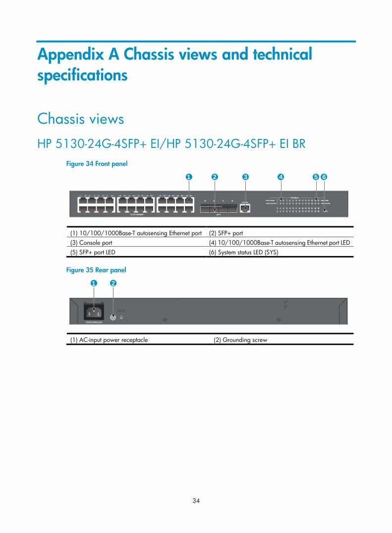
HP 5130-24G-4SFP+ EI/HP 5130-24G-4SFP+ EI BR Figure 34 Front panel
(1) 10/100/1000Base-T autosensing Ethernet port (2) SFP+ port (3) Console port (4) 10/100/1000Base-T autosensing Ethernet port LED (5) SFP+ port LED (6) System status LED (SYS)
Figure 35 Rear panel
(1) AC-input power receptacle (2) Grounding screw
1 2 3 4 5 6
1 2
35
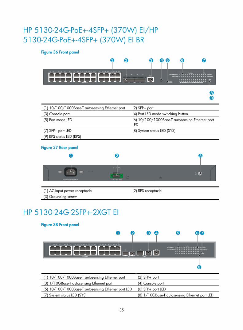
HP 5130-24G-PoE+-4SFP+ (370W) EI/HP 5130-24G-PoE+-4SFP+ (370W) EI BR
Figure 36 Front panel
(1) 10/100/1000Base-T autosensing Ethernet port (2) SFP+ port (3) Console port (4) Port LED mode switching button (5) Port mode LED (6) 10/100/1000Base-T autosensing Ethernet port
LED (7) SFP+ port LED (8) System status LED (SYS) (9) RPS status LED (RPS)
Figure 37 Rear panel
(1) AC-input power receptacle (2) RPS receptacle (3) Grounding screw
HP 5130-24G-2SFP+-2XGT EI Figure 38 Front panel
(1) 10/100/1000Base-T autosensing Ethernet port (2) SFP+ port (3) 1/10GBase-T autosensing Ethernet port (4) Console port (5) 10/100/1000Base-T autosensing Ethernet port LED (6) SFP+ port LED (7) System status LED (SYS) (8) 1/10GBase-T autosensing Ethernet port LED
1 2 3 4 5 6
8
7
9
1 2 3
8
1 2 3 4 5 6 7
36
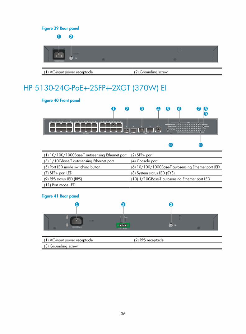
Figure 39 Rear panel
(1) AC-input power receptacle (2) Grounding screw
HP 5130-24G-PoE+-2SFP+-2XGT (370W) EI Figure 40 Front panel
(1) 10/100/1000Base-T autosensing Ethernet port (2) SFP+ port (3) 1/10GBase-T autosensing Ethernet port (4) Console port (5) Port LED mode switching button (6) 10/100/1000Base-T autosensing Ethernet port LED (7) SFP+ port LED (8) System status LED (SYS) (9) RPS status LED (RPS) (10) 1/10GBase-T autosensing Ethernet port LED (11) Port mode LED
Figure 41 Rear panel
(1) AC-input power receptacle (2) RPS receptacle (3) Grounding screw
1 2
1 3 4 62 5 89
7
1011
2 31
37
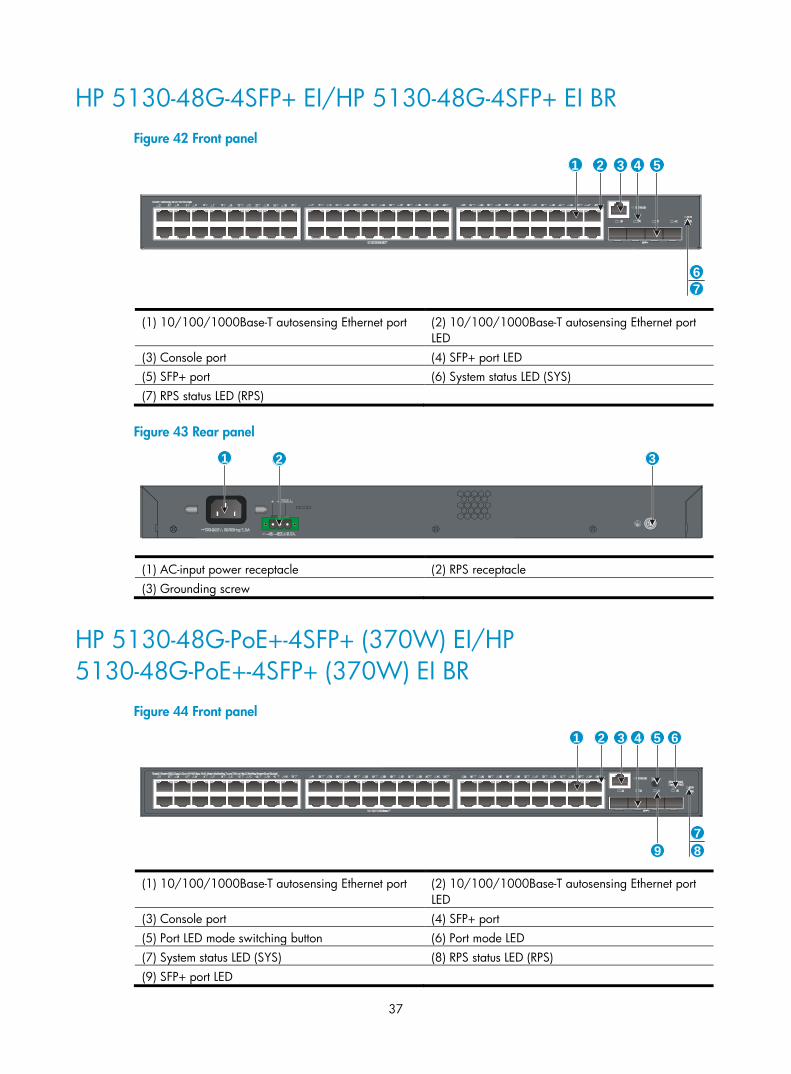
HP 5130-48G-4SFP+ EI/HP 5130-48G-4SFP+ EI BR Figure 42 Front panel
(1) 10/100/1000Base-T autosensing Ethernet port (2) 10/100/1000Base-T autosensing Ethernet port LED
(3) Console port (4) SFP+ port LED (5) SFP+ port (6) System status LED (SYS) (7) RPS status LED (RPS)
Figure 43 Rear panel
(1) AC-input power receptacle (2) RPS receptacle (3) Grounding screw
HP 5130-48G-PoE+-4SFP+ (370W) EI/HP 5130-48G-PoE+-4SFP+ (370W) EI BR
Figure 44 Front panel
(1) 10/100/1000Base-T autosensing Ethernet port (2) 10/100/1000Base-T autosensing Ethernet port LED
(3) Console port (4) SFP+ port (5) Port LED mode switching button (6) Port mode LED (7) System status LED (SYS) (8) RPS status LED (RPS) (9) SFP+ port LED
1 2 3
7
4 5
6
1 2 3
1 2 3 4 5 6
789
38
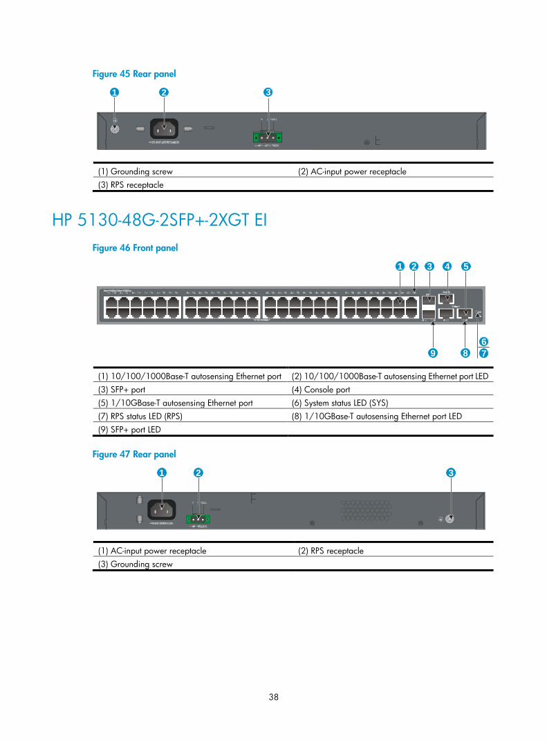
Figure 45 Rear panel
(1) Grounding screw (2) AC-input power receptacle (3) RPS receptacle
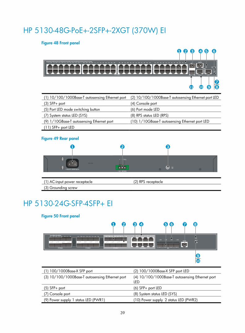
HP 5130-48G-2SFP+-2XGT EI Figure 46 Front panel
(1) 10/100/1000Base-T autosensing Ethernet port (2) 10/100/1000Base-T autosensing Ethernet port LED (3) SFP+ port (4) Console port (5) 1/10GBase-T autosensing Ethernet port (6) System status LED (SYS) (7) RPS status LED (RPS) (8) 1/10GBase-T autosensing Ethernet port LED (9) SFP+ port LED
Figure 47 Rear panel
(1) AC-input power receptacle (2) RPS receptacle (3) Grounding screw
1 2 3
1 2 3
7
4 5
69 8
1 2 3
39
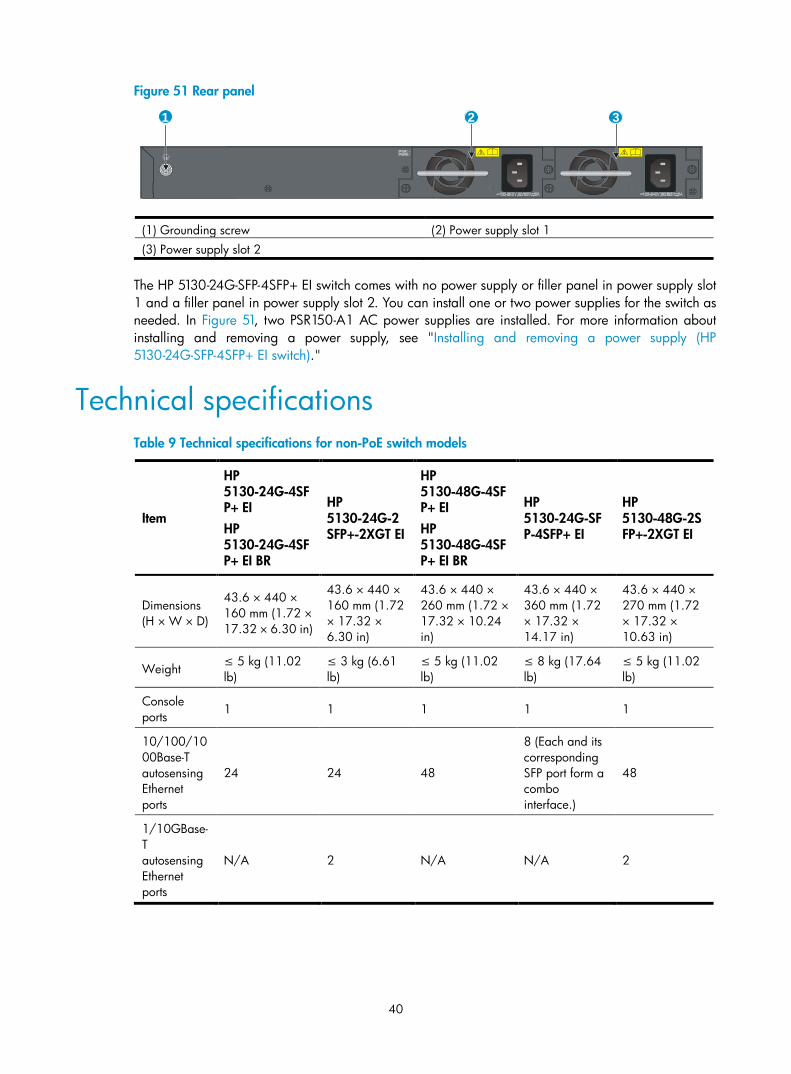
HP 5130-48G-PoE+-2SFP+-2XGT (370W) EI Figure 48 Front panel
(1) 10/100/1000Base-T autosensing Ethernet port (2) 10/100/1000Base-T autosensing Ethernet port LED (3) SFP+ port (4) Console port (5) Port LED mode switching button (6) Port mode LED (7) System status LED (SYS) (8) RPS status LED (RPS) (9) 1/10GBase-T autosensing Ethernet port (10) 1/10GBase-T autosensing Ethernet port LED (11) SFP+ port LED
Figure 49 Rear panel
(1) AC-input power receptacle (2) RPS receptacle (3) Grounding screw
HP 5130-24G-SFP-4SFP+ EI Figure 50 Front panel
(1) 100/1000Base-X SFP port (2) 100/1000Base-X SFP port LED (3) 10/100/1000Base-T autosensing Ethernet port (4) 10/100/1000Base-T autosensing Ethernet port
LED (5) SFP+ port (6) SFP+ port LED (7) Console port (8) System status LED (SYS) (9) Power supply 1 status LED (PWR1) (10) Power supply 2 status LED (PWR2)
78910
321 4 5 6
11
1 2 3
1 2 3 4 5 6 7 8
910
40
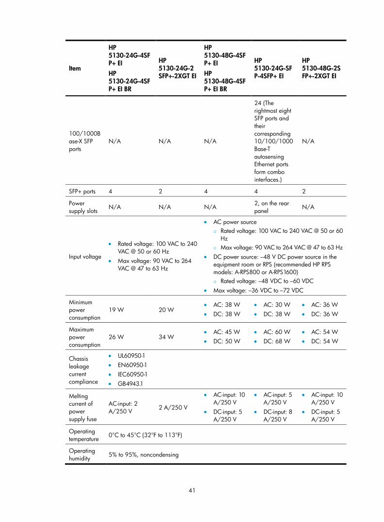
Figure 51 Rear panel
(1) Grounding screw (2) Power supply slot 1 (3) Power supply slot 2
The HP 5130-24G-SFP-4SFP+ EI switch comes with no power supply or filler panel in power supply slot 1 and a filler panel in power supply slot 2. You can install one or two power supplies for the switch as needed. In Figure 51, two PSR150-A1 AC power supplies are installed. For more information about installing and removing a power supply, see "Installing and removing a power supply (HP 5130-24G-SFP-4SFP+ EI switch)."
Technical specifications Table 9 Technical specifications for non-PoE switch models
Item
HP 5130-24G-4SFP+ EI HP 5130-24G-4SFP+ EI BR
HP 5130-24G-2SFP+-2XGT EI
HP 5130-48G-4SFP+ EI HP 5130-48G-4SFP+ EI BR
HP 5130-24G-SFP-4SFP+ EI
HP 5130-48G-2SFP+-2XGT EI
Dimensions (H × W × D)
43.6 × 440 × 160 mm (1.72 × 17.32 × 6.30 in)
43.6 × 440 × 160 mm (1.72 × 17.32 × 6.30 in)
43.6 × 440 × 260 mm (1.72 × 17.32 × 10.24 in)
43.6 × 440 × 360 mm (1.72 × 17.32 × 14.17 in)
43.6 × 440 × 270 mm (1.72 × 17.32 × 10.63 in)
Weight ≤ 5 kg (11.02 lb)
≤ 3 kg (6.61 lb)
≤ 5 kg (11.02 lb)
≤ 8 kg (17.64 lb)
≤ 5 kg (11.02 lb)
Console ports 1 1 1 1 1
10/100/1000Base-T autosensing Ethernet ports
24 24 48
8 (Each and its corresponding SFP port form a combo interface.)
48
1/10GBase-T autosensing Ethernet ports
N/A 2 N/A N/A 2
1 2 3
41
Item
HP 5130-24G-4SFP+ EI HP 5130-24G-4SFP+ EI BR
HP 5130-24G-2SFP+-2XGT EI
HP 5130-48G-4SFP+ EI HP 5130-48G-4SFP+ EI BR
HP 5130-24G-SFP-4SFP+ EI
HP 5130-48G-2SFP+-2XGT EI
100/1000Base-X SFP ports
N/A N/A N/A
24 (The rightmost eight SFP ports and their corresponding 10/100/1000Base-T autosensing Ethernet ports form combo interfaces.)
N/A
SFP+ ports 4 2 4 4 2
Power supply slots
N/A N/A N/A 2, on the rear panel
N/A
Input voltage
• Rated voltage: 100 VAC to 240 VAC @ 50 or 60 Hz
• Max voltage: 90 VAC to 264 VAC @ 47 to 63 Hz
• AC power source Rated voltage: 100 VAC to 240 VAC @ 50 or 60
Hz Max voltage: 90 VAC to 264 VAC @ 47 to 63 Hz
• DC power source: –48 V DC power source in the equipment room or RPS (recommended HP RPS models: A-RPS800 or A-RPS1600) Rated voltage: –48 VDC to –60 VDC
• Max voltage: –36 VDC to –72 VDC
Minimum power consumption
19 W 20 W • AC: 38 W • DC: 38 W
• AC: 30 W • DC: 38 W
• AC: 36 W • DC: 36 W
Maximum power consumption
26 W 34 W • AC: 45 W • DC: 50 W
• AC: 60 W • DC: 68 W
• AC: 54 W • DC: 54 W
Chassis leakage current compliance
• UL60950-1 • EN60950-1 • IEC60950-1 • GB4943.1
Melting current of power supply fuse
AC-input: 2 A/250 V 2 A/250 V
• AC-input: 10 A/250 V
• DC-input: 5 A/250 V
• AC-input: 5 A/250 V
• DC-input: 8 A/250 V
• AC-input: 10 A/250 V
• DC-input: 5 A/250 V
Operating temperature
0°C to 45°C (32°F to 113°F)
Operating humidity 5% to 95%, noncondensing
42
Item
HP 5130-24G-4SFP+ EI HP 5130-24G-4SFP+ EI BR
HP 5130-24G-2SFP+-2XGT EI
HP 5130-48G-4SFP+ EI HP 5130-48G-4SFP+ EI BR
HP 5130-24G-SFP-4SFP+ EI
HP 5130-48G-2SFP+-2XGT EI
Fire resistance compliance
• UL60950-1 • EN60950-1 • IEC60950-1 • GB4943.1
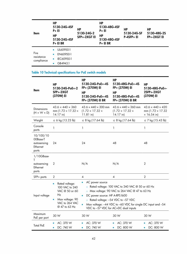
Table 10 Technical specifications for PoE switch models
Item
HP 5130-24G-PoE+-2SFP+-2XGT (370W) EI
HP 5130-24G-PoE+-4SFP+ (370W) EI HP 5130-24G-PoE+-4SFP+ (370W) EI BR
HP 5130-48G-PoE+-4SFP+ (370W) EI HP 5130-48G-PoE+-4SFP+ (370W) EI BR
HP 5130-48G-PoE+-2SFP+-2XGT (370W) EI
Dimensions (H × W × D)
43.6 × 440 × 360 mm (1.72 × 17.32 × 14.17 in)
43.6 × 440 × 300 mm (1.72 × 17.32 × 11.81 in)
43.6 × 440 × 360 mm (1.72 × 17.32 × 14.17 in)
43.6 × 440 × 420 mm (1.72 × 17.32 × 16.54 in)
Weight ≤ 6 kg (13.23 lb) ≤ 8 kg (17.64 lb) ≤ 8 kg (17.64 lb) ≤ 7 kg (15.43 lb)
Console ports
1 1 1 1
10/100/1000Base-T autosensing Ethernet ports
24 24 48 48
1/10GBase-T autosensing Ethernet ports
2 N/A N/A 2
SFP+ ports 2 4 4 2
Input voltage
• Rated voltage: 100 VAC to 240 VAC @ 50 or 60 Hz
• Max voltage: 90 VAC to 264 VAC @ 47 to 63 Hz
• AC power source Rated voltage: 100 VAC to 240 VAC @ 50 or 60 Hz Max voltage: 90 VAC to 264 VAC @ 47 to 63 Hz
• DC power source: HP A-RPS1600 Rated voltage: –54 VDC to –57 VDC
• Max voltage: –44 VDC to –60 VDC for single DC input and –54 VDC to –57 VDC for AC+DC dual inputs
Maximum PoE per port
30 W 30 W 30 W 30 W
Total PoE • AC: 370 W • DC: 740 W
• AC: 370 W • DC: 740 W
• AC: 370 W • DC: 800 W
• AC: 370 W • DC: 800 W
43
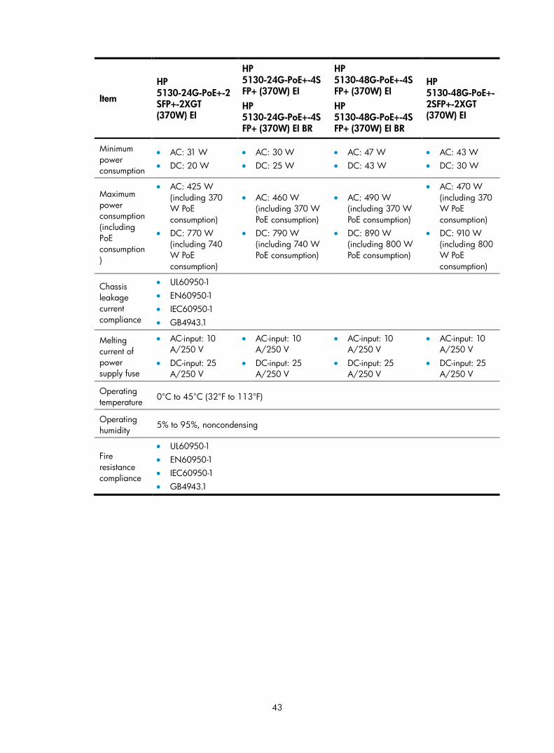
Item
HP 5130-24G-PoE+-2SFP+-2XGT (370W) EI
HP 5130-24G-PoE+-4SFP+ (370W) EI HP 5130-24G-PoE+-4SFP+ (370W) EI BR
HP 5130-48G-PoE+-4SFP+ (370W) EI HP 5130-48G-PoE+-4SFP+ (370W) EI BR
HP 5130-48G-PoE+-2SFP+-2XGT (370W) EI
Minimum power consumption
• AC: 31 W • DC: 20 W
• AC: 30 W • DC: 25 W
• AC: 47 W • DC: 43 W
• AC: 43 W • DC: 30 W
Maximum power consumption (including PoE consumption)
• AC: 425 W (including 370 W PoE consumption)
• DC: 770 W (including 740 W PoE consumption)
• AC: 460 W (including 370 W PoE consumption)
• DC: 790 W (including 740 W PoE consumption)
• AC: 490 W (including 370 W PoE consumption)
• DC: 890 W (including 800 W PoE consumption)
• AC: 470 W (including 370 W PoE consumption)
• DC: 910 W (including 800 W PoE consumption)
Chassis leakage current compliance
• UL60950-1 • EN60950-1 • IEC60950-1 • GB4943.1
Melting current of power supply fuse
• AC-input: 10 A/250 V
• DC-input: 25 A/250 V
• AC-input: 10 A/250 V
• DC-input: 25 A/250 V
• AC-input: 10 A/250 V
• DC-input: 25 A/250 V
• AC-input: 10 A/250 V
• DC-input: 25 A/250 V
Operating temperature 0°C to 45°C (32°F to 113°F)
Operating humidity
5% to 95%, noncondensing
Fire resistance compliance
• UL60950-1 • EN60950-1 • IEC60950-1 • GB4943.1
44
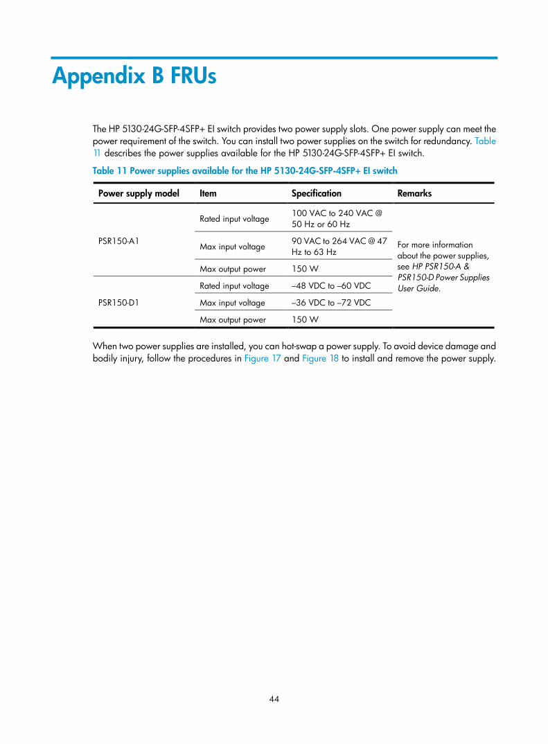
Appendix B FRUs
The HP 5130-24G-SFP-4SFP+ EI switch provides two power supply slots. One power supply can meet the power requirement of the switch. You can install two power supplies on the switch for redundancy. Table 11 describes the power supplies available for the HP 5130-24G-SFP-4SFP+ EI switch.
Table 11 Power supplies available for the HP 5130-24G-SFP-4SFP+ EI switch
Power supply model Item Specification Remarks
PSR150-A1
Rated input voltage 100 VAC to 240 VAC @ 50 Hz or 60 Hz
For more information about the power supplies, see HP PSR150-A & PSR150-D Power Supplies User Guide.
Max input voltage 90 VAC to 264 VAC @ 47 Hz to 63 Hz
Max output power 150 W
PSR150-D1
Rated input voltage –48 VDC to –60 VDC
Max input voltage –36 VDC to –72 VDC
Max output power 150 W
When two power supplies are installed, you can hot-swap a power supply. To avoid device damage and bodily injury, follow the procedures in Figure 17 and Figure 18 to install and remove the power supply.
45
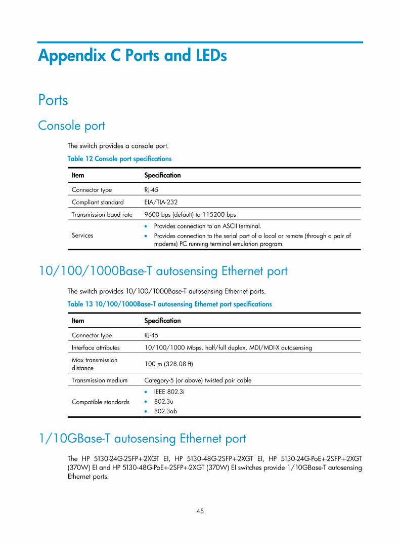
Appendix C Ports and LEDs
Ports
Console port The switch provides a console port.
Table 12 Console port specifications
Item Specification
Connector type RJ-45
Compliant standard EIA/TIA-232
Transmission baud rate 9600 bps (default) to 115200 bps
Services • Provides connection to an ASCII terminal. • Provides connection to the serial port of a local or remote (through a pair of
modems) PC running terminal emulation program.
10/100/1000Base-T autosensing Ethernet port The switch provides 10/100/1000Base-T autosensing Ethernet ports.
Table 13 10/100/1000Base-T autosensing Ethernet port specifications
Item Specification
Connector type RJ-45
Interface attributes 10/100/1000 Mbps, half/full duplex, MDI/MDI-X autosensing
Max transmission distance
100 m (328.08 ft)
Transmission medium Category-5 (or above) twisted pair cable
Compatible standards
• IEEE 802.3i • 802.3u • 802.3ab
1/10GBase-T autosensing Ethernet port The HP 5130-24G-2SFP+-2XGT EI, HP 5130-48G-2SFP+-2XGT EI, HP 5130-24G-PoE+-2SFP+-2XGT (370W) EI and HP 5130-48G-PoE+-2SFP+-2XGT (370W) EI switches provide 1/10GBase-T autosensing Ethernet ports.
46
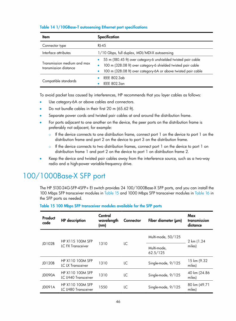
Table 14 1/10GBase-T autosensing Ethernet port specifications
Item Specification
Connector type RJ-45
Interface attributes 1/10 Gbps, full duplex, MDI/MDI-X autosensing
Transmission medium and max transmission distance
• 55 m (180.45 ft) over category-6 unshielded twisted pair cable • 100 m (328.08 ft) over category-6 shielded twisted pair cable • 100 m (328.08 ft) over category-6A or above twisted pair cable
Compatible standards • IEEE 802.3ab • IEEE 802.3an
To avoid packet loss caused by interferences, HP recommends that you layer cables as follows:
• Use category-6A or above cables and connectors.
• Do not bundle cables in their first 20 m (65.62 ft).
• Separate power cords and twisted pair cables at and around the distribution frame.
• For ports adjacent to one another on the device, the peer ports on the distribution frame is preferably not adjacent, for example:
If the device connects to one distribution frame, connect port 1 on the device to port 1 on the distribution frame and port 2 on the device to port 3 on the distribution frame.
If the device connects to two distribution frames, connect port 1 on the device to port 1 on distribution frame 1 and port 2 on the device to port 1 on distribution frame 2.
• Keep the device and twisted pair cables away from the interference source, such as a two-way radio and a high-power variable-frequency drive.
100/1000Base-X SFP port The HP 5130-24G-SFP-4SFP+ EI switch provides 24 100/1000Base-X SFP ports, and you can install the 100 Mbps SFP transceiver modules in Table 15 and 1000 Mbps SFP transceiver modules in Table 16 in the SFP ports as needed.
Table 15 100 Mbps SFP transceiver modules available for the SFP ports
Product code HP description
Central wavelength (nm)
Connector Fiber diameter (µm) Max transmission distance
JD102B HP X115 100M SFP LC FX Transceiver 1310 LC
Multi-mode, 50/125 2 km (1.24 miles) Multi-mode,
62.5/125
JD120B HP X110 100M SFP LC LX Transceiver 1310 LC Single-mode, 9/125
15 km (9.32 miles)
JD090A HP X110 100M SFP LC LH40 Transceiver
1310 LC Single-mode, 9/125 40 km (24.86 miles)
JD091A HP X110 100M SFP LC LH80 Transceiver 1550 LC Single-mode, 9/125
80 km (49.71 miles)
47
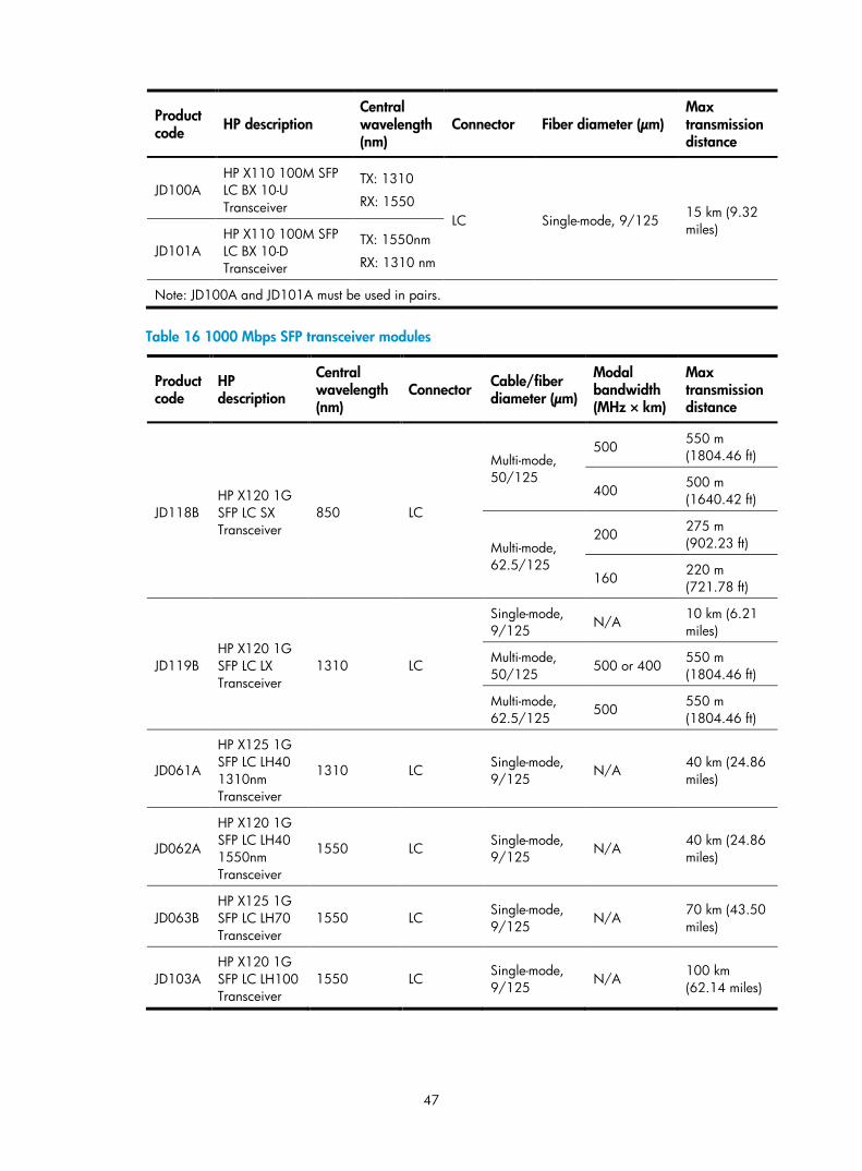
Product code HP description
Central wavelength (nm)
Connector Fiber diameter (µm) Max transmission distance
JD100A HP X110 100M SFP LC BX 10-U Transceiver
TX: 1310
RX: 1550 LC Single-mode, 9/125 15 km (9.32
miles)
JD101A HP X110 100M SFP LC BX 10-D Transceiver
TX: 1550nm
RX: 1310 nm
Note: JD100A and JD101A must be used in pairs.
Table 16 1000 Mbps SFP transceiver modules
Product code
HP description
Central wavelength (nm)
Connector Cable/fiber diameter (µm)
Modal bandwidth (MHz × km)
Max transmission distance
JD118B HP X120 1G SFP LC SX Transceiver
850 LC
Multi-mode, 50/125
500 550 m (1804.46 ft)
400 500 m (1640.42 ft)
Multi-mode, 62.5/125
200 275 m (902.23 ft)
160 220 m (721.78 ft)
JD119B HP X120 1G SFP LC LX Transceiver
1310 LC
Single-mode, 9/125
N/A 10 km (6.21 miles)
Multi-mode, 50/125
500 or 400 550 m (1804.46 ft)
Multi-mode, 62.5/125
500 550 m (1804.46 ft)
JD061A
HP X125 1G SFP LC LH40 1310nm Transceiver
1310 LC Single-mode, 9/125
N/A 40 km (24.86 miles)
JD062A
HP X120 1G SFP LC LH40 1550nm Transceiver
1550 LC Single-mode, 9/125 N/A 40 km (24.86
miles)
JD063B HP X125 1G SFP LC LH70 Transceiver
1550 LC Single-mode, 9/125
N/A 70 km (43.50 miles)
JD103A HP X120 1G SFP LC LH100 Transceiver
1550 LC Single-mode, 9/125
N/A 100 km (62.14 miles)
48
Product code
HP description
Central wavelength (nm)
Connector Cable/fiber diameter (µm)
Modal bandwidth (MHz × km)
Max transmission distance
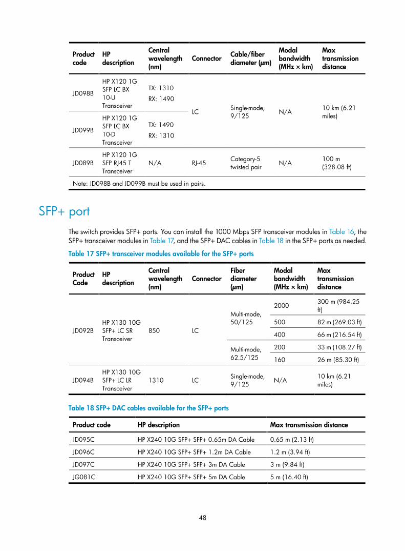
JD098B
HP X120 1G SFP LC BX 10-U Transceiver
TX: 1310
RX: 1490
LC Single-mode, 9/125
N/A 10 km (6.21 miles)
JD099B
HP X120 1G SFP LC BX 10-D Transceiver
TX: 1490
RX: 1310
JD089B HP X120 1G SFP RJ45 T Transceiver
N/A RJ-45 Category-5 twisted pair N/A
100 m (328.08 ft)
Note: JD098B and JD099B must be used in pairs.
SFP+ port The switch provides SFP+ ports. You can install the 1000 Mbps SFP transceiver modules in Table 16, the SFP+ transceiver modules in Table 17, and the SFP+ DAC cables in Table 18 in the SFP+ ports as needed.
Table 17 SFP+ transceiver modules available for the SFP+ ports
Product Code
HP description
Central wavelength (nm)
Connector Fiber diameter (µm)
Modal bandwidth (MHz × km)
Max transmission distance
JD092B HP X130 10G SFP+ LC SR Transceiver
850 LC
Multi-mode, 50/125
2000 300 m (984.25 ft)
500 82 m (269.03 ft)
400 66 m (216.54 ft)
Multi-mode, 62.5/125
200 33 m (108.27 ft)
160 26 m (85.30 ft)
JD094B HP X130 10G SFP+ LC LR Transceiver
1310 LC Single-mode, 9/125
N/A 10 km (6.21 miles)
Table 18 SFP+ DAC cables available for the SFP+ ports
Product code HP description Max transmission distance
JD095C HP X240 10G SFP+ SFP+ 0.65m DA Cable 0.65 m (2.13 ft)
JD096C HP X240 10G SFP+ SFP+ 1.2m DA Cable 1.2 m (3.94 ft)
JD097C HP X240 10G SFP+ SFP+ 3m DA Cable 3 m (9.84 ft)
JG081C HP X240 10G SFP+ SFP+ 5m DA Cable 5 m (16.40 ft)
49
NOTE:
HP recommends that you use HP 1000 Mbps SFP transceiver modules, SFP+ transceiver modules, or SFP+ DAC cables for the SFP+ ports on the switch. The HP 1000 Mbps SFP and SFP+ transceiver modules are subject to change over time. For the most up-to-date list of SFP and SFP+ transceiver modules, contact your HP sales representative or technical support engineer.
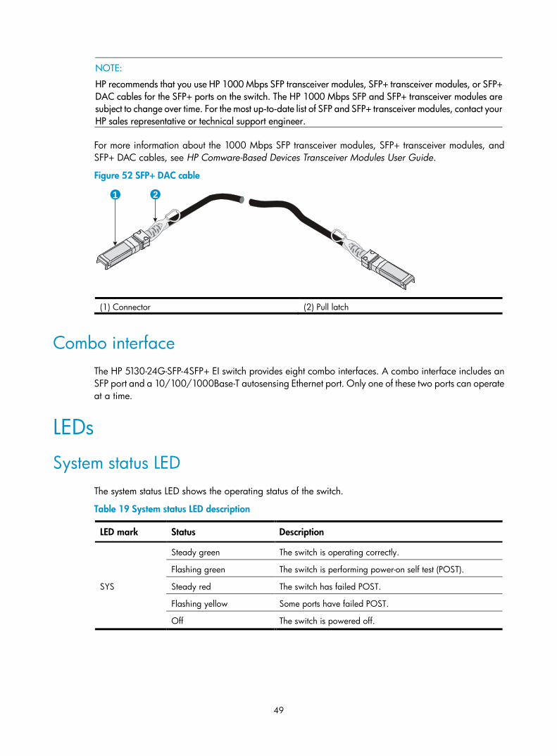
For more information about the 1000 Mbps SFP transceiver modules, SFP+ transceiver modules, and SFP+ DAC cables, see HP Comware-Based Devices Transceiver Modules User Guide.
Figure 52 SFP+ DAC cable
(1) Connector (2) Pull latch
Combo interface The HP 5130-24G-SFP-4SFP+ EI switch provides eight combo interfaces. A combo interface includes an SFP port and a 10/100/1000Base-T autosensing Ethernet port. Only one of these two ports can operate at a time.
LEDs
System status LED The system status LED shows the operating status of the switch.
Table 19 System status LED description
LED mark Status Description
SYS
Steady green The switch is operating correctly.
Flashing green The switch is performing power-on self test (POST).
Steady red The switch has failed POST.
Flashing yellow Some ports have failed POST.
Off The switch is powered off.
1 2
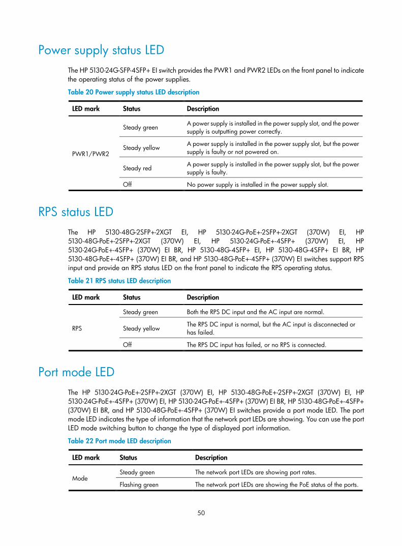
50
Power supply status LED The HP 5130-24G-SFP-4SFP+ EI switch provides the PWR1 and PWR2 LEDs on the front panel to indicate the operating status of the power supplies.
Table 20 Power supply status LED description
LED mark Status Description
PWR1/PWR2
Steady green A power supply is installed in the power supply slot, and the power supply is outputting power correctly.
Steady yellow A power supply is installed in the power supply slot, but the power supply is faulty or not powered on.
Steady red A power supply is installed in the power supply slot, but the power supply is faulty.
Off No power supply is installed in the power supply slot.
RPS status LED The HP 5130-48G-2SFP+-2XGT EI, HP 5130-24G-PoE+-2SFP+-2XGT (370W) EI, HP 5130-48G-PoE+-2SFP+-2XGT (370W) EI, HP 5130-24G-PoE+-4SFP+ (370W) EI, HP 5130-24G-PoE+-4SFP+ (370W) EI BR, HP 5130-48G-4SFP+ EI, HP 5130-48G-4SFP+ EI BR, HP 5130-48G-PoE+-4SFP+ (370W) EI BR, and HP 5130-48G-PoE+-4SFP+ (370W) EI switches support RPS input and provide an RPS status LED on the front panel to indicate the RPS operating status.
Table 21 RPS status LED description
LED mark Status Description
RPS
Steady green Both the RPS DC input and the AC input are normal.
Steady yellow The RPS DC input is normal, but the AC input is disconnected or has failed.
Off The RPS DC input has failed, or no RPS is connected.
Port mode LED The HP 5130-24G-PoE+-2SFP+-2XGT (370W) EI, HP 5130-48G-PoE+-2SFP+-2XGT (370W) EI, HP 5130-24G-PoE+-4SFP+ (370W) EI, HP 5130-24G-PoE+-4SFP+ (370W) EI BR, HP 5130-48G-PoE+-4SFP+ (370W) EI BR, and HP 5130-48G-PoE+-4SFP+ (370W) EI switches provide a port mode LED. The port mode LED indicates the type of information that the network port LEDs are showing. You can use the port LED mode switching button to change the type of displayed port information.
Table 22 Port mode LED description
LED mark Status Description
Mode Steady green The network port LEDs are showing port rates.
Flashing green The network port LEDs are showing the PoE status of the ports.
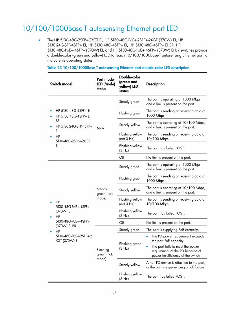
51
10/100/1000Base-T autosensing Ethernet port LED • The HP 5130-48G-2SFP+-2XGT EI, HP 5130-48G-PoE+-2SFP+-2XGT (370W) EI, HP
5130-24G-SFP-4SFP+ EI, HP 5130-48G-4SFP+ EI, HP 5130-48G-4SFP+ EI BR, HP 5130-48G-PoE+-4SFP+ (370W) EI, and HP 5130-48G-PoE+-4SFP+ (370W) EI BR switches provide a double-color (green and yellow) LED for each 10/100/1000Base-T autosensing Ethernet port to indicate its operating status.
Table 23 10/100/1000Base-T autosensing Ethernet port double-color LED description
Switch model Port mode LED (Mode) status
Double-color (green and yellow) LED status
Description
• HP 5130-48G-4SFP+ EI • HP 5130-48G-4SFP+ EI
BR • HP 5130-24G-SFP-4SFP+
EI • HP
5130-48G-2SFP+-2XGT EI
N/A
Steady green The port is operating at 1000 Mbps, and a link is present on the port.
Flashing green The port is sending or receiving data at 1000 Mbps.
Steady yellow The port is operating at 10/100 Mbps, and a link is present on the port.
Flashing yellow (not 3 Hz)
The port is sending or receiving data at 10/100 Mbps.
Flashing yellow (3 Hz) The port has failed POST.
Off No link is present on the port.
• HP 5130-48G-PoE+-4SFP+ (370W) EI
• HP 5130-48G-PoE+-4SFP+ (370W) EI BR
• HP 5130-48G-PoE+-2SFP+-2XGT (370W) EI
Steady green (rate mode)
Steady green The port is operating at 1000 Mbps, and a link is present on the port.
Flashing green The port is sending or receiving data at 1000 Mbps.
Steady yellow The port is operating at 10/100 Mbps, and a link is present on the port.
Flashing yellow (not 3 Hz)
The port is sending or receiving data at 10/100 Mbps.
Flashing yellow (3 Hz)
The port has failed POST.
Off No link is present on the port.
Flashing green (PoE mode)
Steady green The port is supplying PoE correctly.
Flashing green (3 Hz)
• The PD power requirement exceeds the port PoE capacity.
• The port fails to meet the power requirement of the PD because of power insufficiency of the switch.
Steady yellow A non-PD device is attached to the port, or the port is experiencing a PoE failure.
Flashing yellow (3 Hz) The port has failed POST.
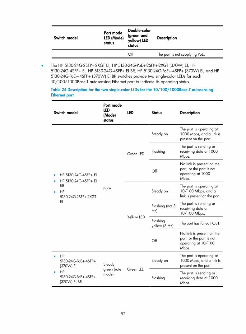
52
Switch model Port mode LED (Mode) status
Double-color (green and yellow) LED status
Description
Off The port is not supplying PoE.
• The HP 5130-24G-2SFP+-2XGT EI, HP 5130-24G-PoE+-2SFP+-2XGT (370W) EI, HP 5130-24G-4SFP+ EI, HP 5130-24G-4SFP+ EI BR, HP 5130-24G-PoE+-4SFP+ (370W) EI, and HP 5130-24G-PoE+-4SFP+ (370W) EI BR switches provide two single-color LEDs for each 10/100/1000Base-T autosensing Ethernet port to indicate its operating status.
Table 24 Description for the two single-color LEDs for the 10/100/1000Base-T autosensing Ethernet port
Switch model
Port mode LED (Mode) status
LED Status Description
• HP 5130-24G-4SFP+ EI • HP 5130-24G-4SFP+ EI
BR • HP
5130-24G-2SFP+-2XGT EI
N/A
Green LED
Steady on The port is operating at 1000 Mbps, and a link is present on the port.
Flashing The port is sending or receiving data at 1000 Mbps.
Off
No link is present on the port, or the port is not operating at 1000 Mbps.
Yellow LED
Steady on The port is operating at 10/100 Mbps, and a link is present on the port.
Flashing (not 3 Hz)
The port is sending or receiving data at 10/100 Mbps.
Flashing yellow (3 Hz)
The port has failed POST.
Off
No link is present on the port, or the port is not operating at 10/100 Mbps.
• HP 5130-24G-PoE+-4SFP+ (370W) EI
• HP 5130-24G-PoE+-4SFP+ (370W) EI BR
Steady green (rate mode)
Green LED
Steady on The port is operating at 1000 Mbps, and a link is present on the port.
Flashing The port is sending or receiving data at 1000 Mbps.
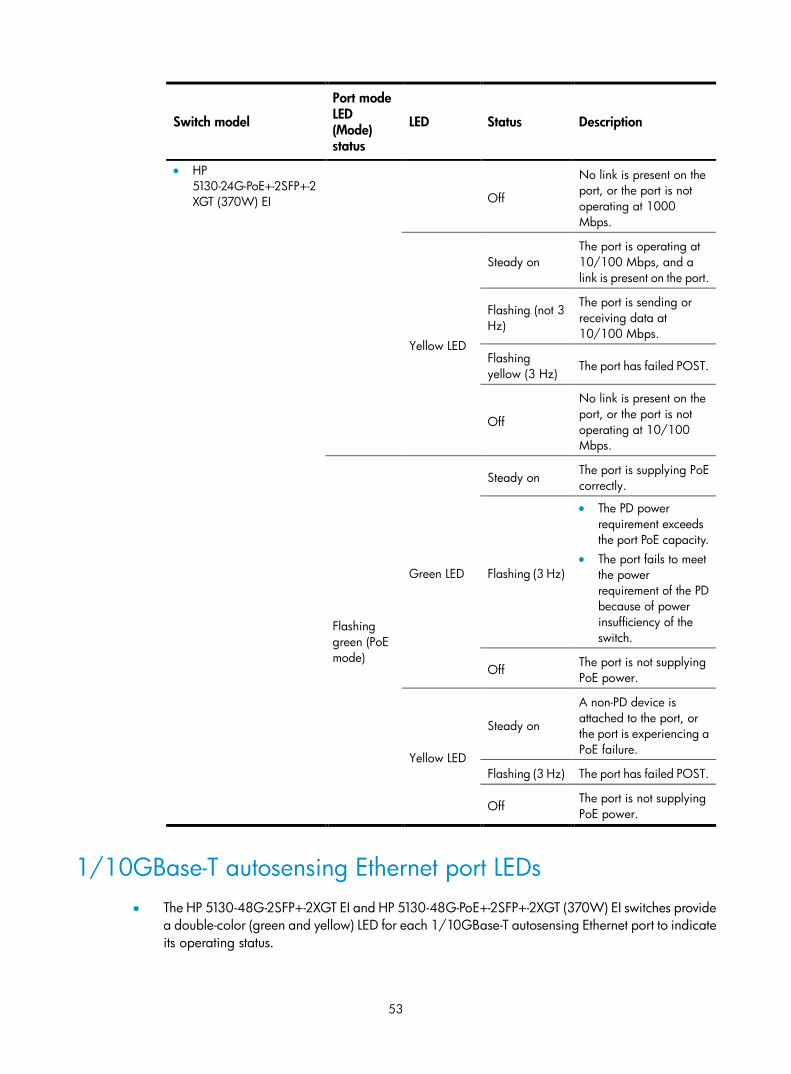
53
Switch model
Port mode LED (Mode) status
LED Status Description
• HP 5130-24G-PoE+-2SFP+-2XGT (370W) EI Off
No link is present on the port, or the port is not operating at 1000 Mbps.
Yellow LED
Steady on The port is operating at 10/100 Mbps, and a link is present on the port.
Flashing (not 3 Hz)
The port is sending or receiving data at 10/100 Mbps.
Flashing yellow (3 Hz)
The port has failed POST.
Off
No link is present on the port, or the port is not operating at 10/100 Mbps.
Flashing green (PoE mode)
Green LED
Steady on The port is supplying PoE correctly.
Flashing (3 Hz)
• The PD power requirement exceeds the port PoE capacity.
• The port fails to meet the power requirement of the PD because of power insufficiency of the switch.
Off The port is not supplying PoE power.
Yellow LED
Steady on
A non-PD device is attached to the port, or the port is experiencing a PoE failure.
Flashing (3 Hz) The port has failed POST.
Off The port is not supplying PoE power.
1/10GBase-T autosensing Ethernet port LEDs • The HP 5130-48G-2SFP+-2XGT EI and HP 5130-48G-PoE+-2SFP+-2XGT (370W) EI switches provide
a double-color (green and yellow) LED for each 1/10GBase-T autosensing Ethernet port to indicate its operating status.
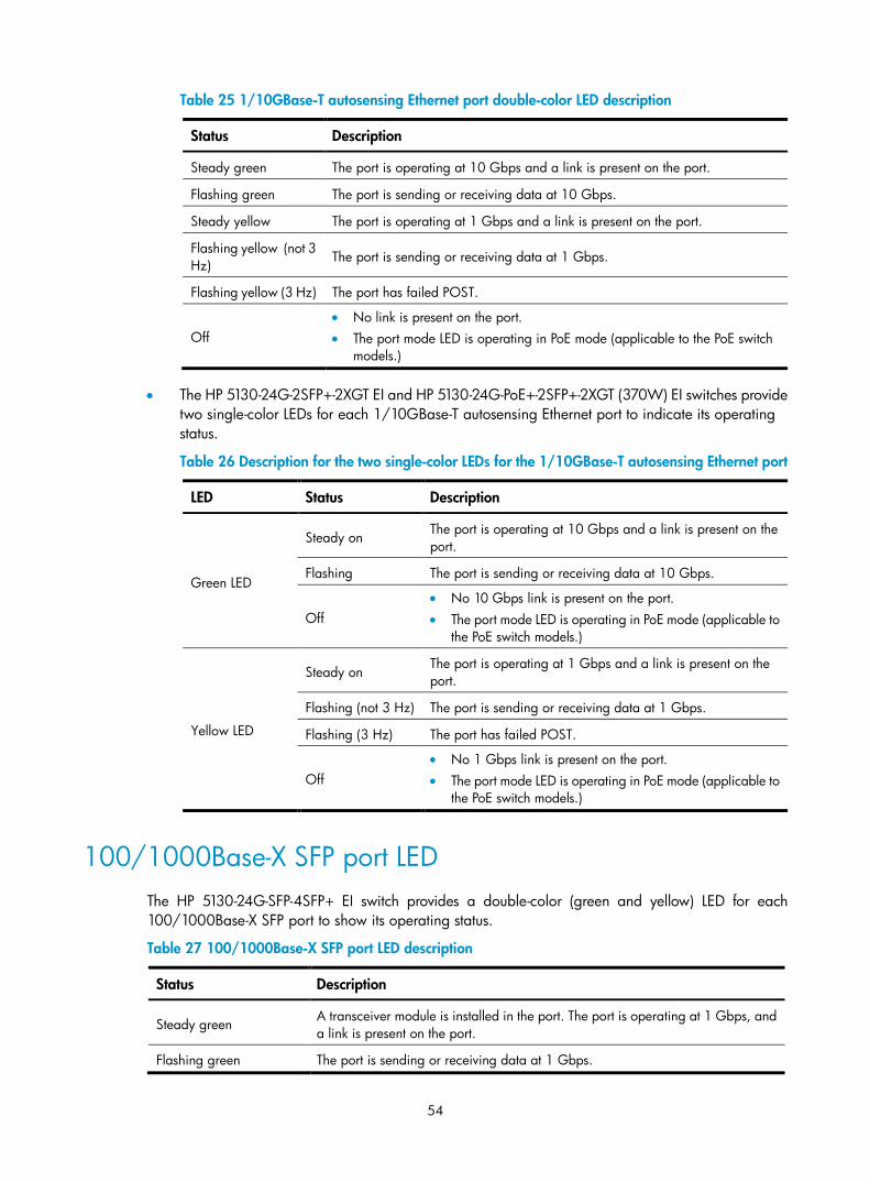
54
Table 25 1/10GBase-T autosensing Ethernet port double-color LED description
Status Description
Steady green The port is operating at 10 Gbps and a link is present on the port.
Flashing green The port is sending or receiving data at 10 Gbps.
Steady yellow The port is operating at 1 Gbps and a link is present on the port.
Flashing yellow (not 3 Hz)
The port is sending or receiving data at 1 Gbps.
Flashing yellow (3 Hz) The port has failed POST.
Off • No link is present on the port. • The port mode LED is operating in PoE mode (applicable to the PoE switch
models.)
• The HP 5130-24G-2SFP+-2XGT EI and HP 5130-24G-PoE+-2SFP+-2XGT (370W) EI switches provide two single-color LEDs for each 1/10GBase-T autosensing Ethernet port to indicate its operating status.
Table 26 Description for the two single-color LEDs for the 1/10GBase-T autosensing Ethernet port
LED Status Description
Green LED
Steady on The port is operating at 10 Gbps and a link is present on the port.
Flashing The port is sending or receiving data at 10 Gbps.
Off • No 10 Gbps link is present on the port. • The port mode LED is operating in PoE mode (applicable to
the PoE switch models.)
Yellow LED
Steady on The port is operating at 1 Gbps and a link is present on the port.
Flashing (not 3 Hz) The port is sending or receiving data at 1 Gbps.
Flashing (3 Hz) The port has failed POST.
Off • No 1 Gbps link is present on the port. • The port mode LED is operating in PoE mode (applicable to
the PoE switch models.)
100/1000Base-X SFP port LED The HP 5130-24G-SFP-4SFP+ EI switch provides a double-color (green and yellow) LED for each 100/1000Base-X SFP port to show its operating status.
Table 27 100/1000Base-X SFP port LED description
Status Description
Steady green A transceiver module is installed in the port. The port is operating at 1 Gbps, and a link is present on the port.
Flashing green The port is sending or receiving data at 1 Gbps.
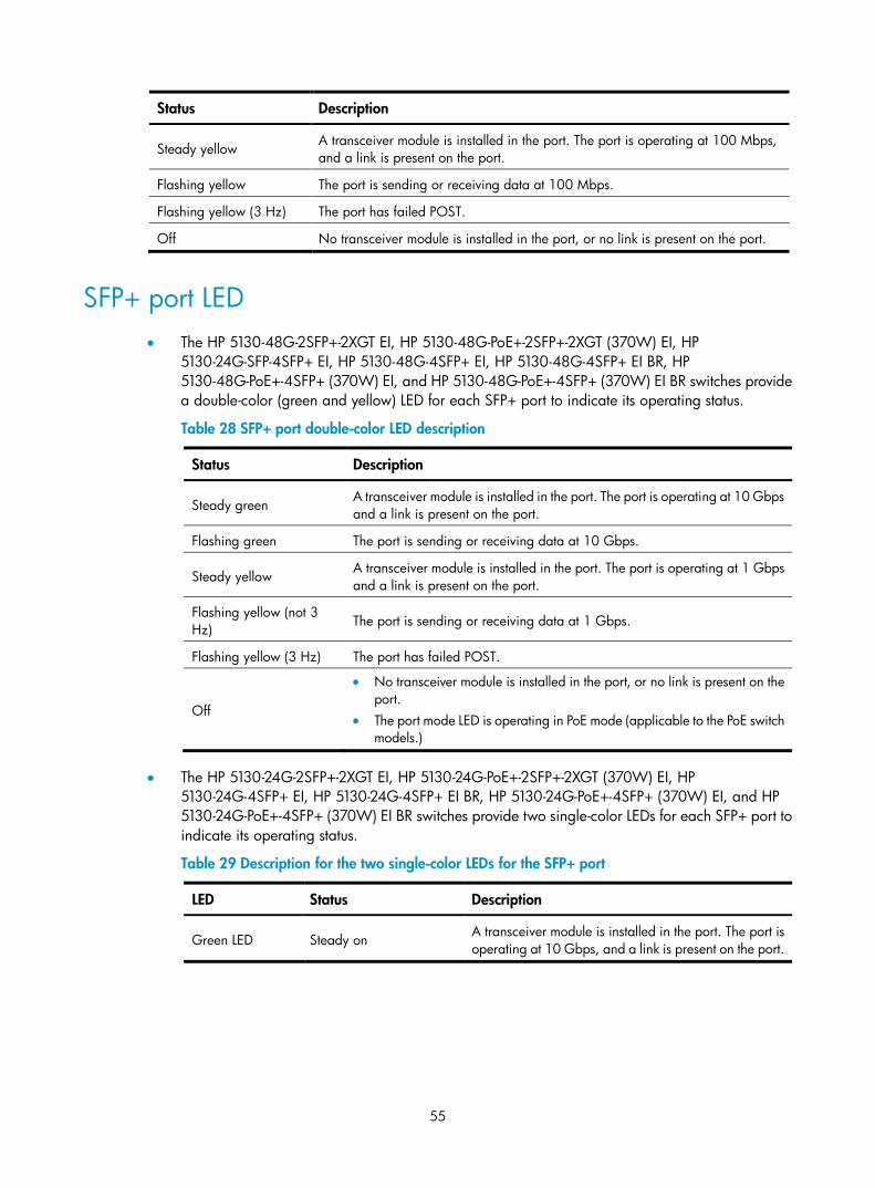
55
Status Description
Steady yellow A transceiver module is installed in the port. The port is operating at 100 Mbps, and a link is present on the port.
Flashing yellow The port is sending or receiving data at 100 Mbps.
Flashing yellow (3 Hz) The port has failed POST.
Off No transceiver module is installed in the port, or no link is present on the port.
SFP+ port LED • The HP 5130-48G-2SFP+-2XGT EI, HP 5130-48G-PoE+-2SFP+-2XGT (370W) EI, HP
5130-24G-SFP-4SFP+ EI, HP 5130-48G-4SFP+ EI, HP 5130-48G-4SFP+ EI BR, HP 5130-48G-PoE+-4SFP+ (370W) EI, and HP 5130-48G-PoE+-4SFP+ (370W) EI BR switches provide a double-color (green and yellow) LED for each SFP+ port to indicate its operating status.
Table 28 SFP+ port double-color LED description
Status Description
Steady green A transceiver module is installed in the port. The port is operating at 10 Gbps and a link is present on the port.
Flashing green The port is sending or receiving data at 10 Gbps.
Steady yellow A transceiver module is installed in the port. The port is operating at 1 Gbps and a link is present on the port.
Flashing yellow (not 3 Hz)
The port is sending or receiving data at 1 Gbps.
Flashing yellow (3 Hz) The port has failed POST.
Off
• No transceiver module is installed in the port, or no link is present on the port.
• The port mode LED is operating in PoE mode (applicable to the PoE switch models.)
• The HP 5130-24G-2SFP+-2XGT EI, HP 5130-24G-PoE+-2SFP+-2XGT (370W) EI, HP 5130-24G-4SFP+ EI, HP 5130-24G-4SFP+ EI BR, HP 5130-24G-PoE+-4SFP+ (370W) EI, and HP 5130-24G-PoE+-4SFP+ (370W) EI BR switches provide two single-color LEDs for each SFP+ port to indicate its operating status.
Table 29 Description for the two single-color LEDs for the SFP+ port
LED Status Description
Green LED Steady on A transceiver module is installed in the port. The port is operating at 10 Gbps, and a link is present on the port.
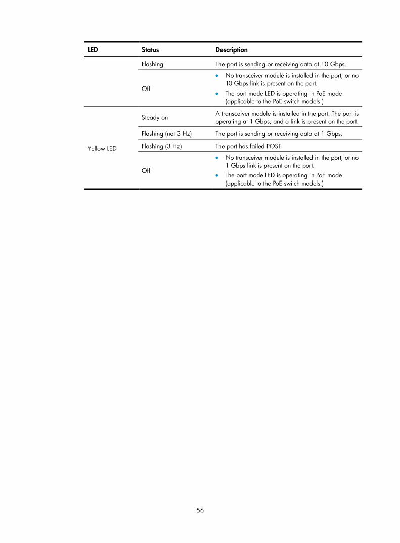
56
LED Status Description
Flashing The port is sending or receiving data at 10 Gbps.
Off
• No transceiver module is installed in the port, or no 10 Gbps link is present on the port.
• The port mode LED is operating in PoE mode (applicable to the PoE switch models.)
Yellow LED
Steady on A transceiver module is installed in the port. The port is operating at 1 Gbps, and a link is present on the port.
Flashing (not 3 Hz) The port is sending or receiving data at 1 Gbps.
Flashing (3 Hz) The port has failed POST.
Off
• No transceiver module is installed in the port, or no 1 Gbps link is present on the port.
• The port mode LED is operating in PoE mode (applicable to the PoE switch models.)
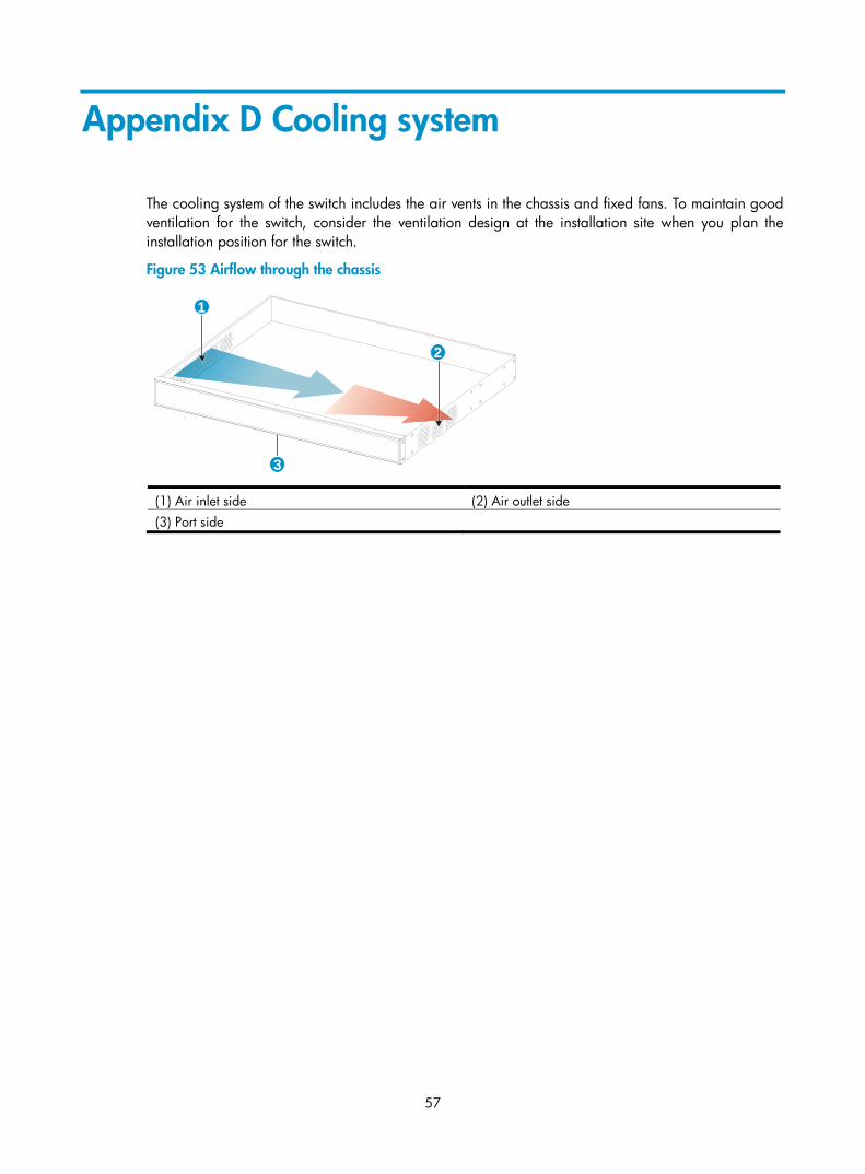
57
Appendix D Cooling system
The cooling system of the switch includes the air vents in the chassis and fixed fans. To maintain good ventilation for the switch, consider the ventilation design at the installation site when you plan the installation position for the switch.
Figure 53 Airflow through the chassis
(1) Air inlet side (2) Air outlet side (3) Port side
3
1
2
58
Support and other resources
Contacting HP For worldwide technical support information, see the HP support website:
http://www.hp.com/support
Before contacting HP, collect the following information:
• Product model names and numbers
• Technical support registration number (if applicable)
• Product serial numbers
• Error messages
• Operating system type and revision level
• Detailed questions
Subscription service HP recommends that you register your product at the Subscriber's Choice for Business website:
http://www.hp.com/go/wwalerts
After registering, you will receive email notification of product enhancements, new driver versions, firmware updates, and other product resources.
Related information
Documents To find related documents, browse to the Manuals page of the HP Business Support Center website:
http://www.hp.com/support/manuals
• For related documentation, navigate to the Networking section, and select a networking category.
• For a complete list of acronyms and their definitions, see HP FlexNetwork Technology Acronyms.
Websites • HP.com http://www.hp.com
• HP Networking http://www.hp.com/go/networking
• HP manuals http://www.hp.com/support/manuals
• HP download drivers and software http://www.hp.com/support/downloads
• HP software depot http://www.software.hp.com
• HP Education http://www.hp.com/learn
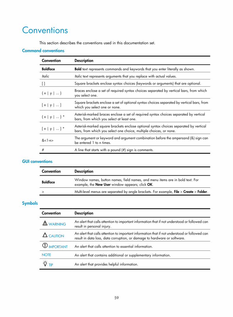
59
Conventions This section describes the conventions used in this documentation set.
Command conventions
Convention Description
Boldface Bold text represents commands and keywords that you enter literally as shown.
Italic Italic text represents arguments that you replace with actual values.
[ ] Square brackets enclose syntax choices (keywords or arguments) that are optional.
{ x | y | ... } Braces enclose a set of required syntax choices separated by vertical bars, from which you select one.
[ x | y | ... ] Square brackets enclose a set of optional syntax choices separated by vertical bars, from which you select one or none.
{ x | y | ... } * Asterisk-marked braces enclose a set of required syntax choices separated by vertical bars, from which you select at least one.
[ x | y | ... ] * Asterisk-marked square brackets enclose optional syntax choices separated by vertical bars, from which you select one choice, multiple choices, or none.
&<1-n> The argument or keyword and argument combination before the ampersand (&) sign can be entered 1 to n times.
# A line that starts with a pound (#) sign is comments.
GUI conventions
Convention Description
Boldface Window names, button names, field names, and menu items are in bold text. For example, the New User window appears; click OK.
> Multi-level menus are separated by angle brackets. For example, File > Create > Folder.
Symbols
Convention Description
WARNING An alert that calls attention to important information that if not understood or followed can result in personal injury.
CAUTION An alert that calls attention to important information that if not understood or followed can result in data loss, data corruption, or damage to hardware or software.
IMPORTANT An alert that calls attention to essential information.
NOTE An alert that contains additional or supplementary information.
TIP An alert that provides helpful information.
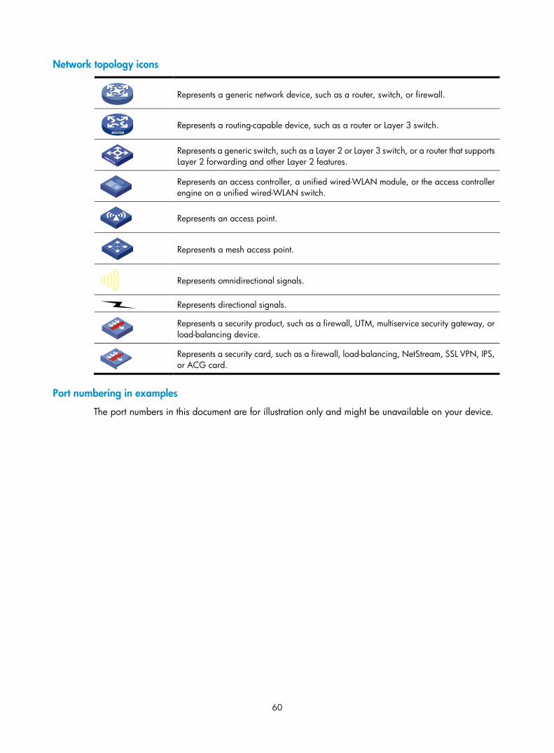
60
Network topology icons
Represents a generic network device, such as a router, switch, or firewall.
Represents a routing-capable device, such as a router or Layer 3 switch.
Represents a generic switch, such as a Layer 2 or Layer 3 switch, or a router that supports Layer 2 forwarding and other Layer 2 features.
Represents an access controller, a unified wired-WLAN module, or the access controller engine on a unified wired-WLAN switch.
Represents an access point.
Represents a mesh access point.
Represents omnidirectional signals.
Represents directional signals.
Represents a security product, such as a firewall, UTM, multiservice security gateway, or load-balancing device.
Represents a security card, such as a firewall, load-balancing, NetStream, SSL VPN, IPS, or ACG card.
Port numbering in examples
The port numbers in this document are for illustration only and might be unavailable on your device.
61
Index
Numerics
10/100/1000 Base-T Ethernet port, 45 port LED, 51
100/1000Base-X SFP port, 46 port LED, 54
19-inch rack switch installation, 6
–48 VDC power source connecting, 18
A
AC power source connecting, 17
AC power supply grounding switch through AC power supply PE wire, 13
access first time switch access, 21
accessories needed for installation, 4 Appendix
A, chassis views and technical specifications, 34, 40 B, FRUs, 44
attaching mounting bracket to switch chassis, 7
B
bits per second (parameter), 22
C
cable connecting console, 21 fiber cable laser safety recommendations, 4 grounding the switch with grounding conductor buried in the earth ground, 13 grounding the switch with grounding strip, 11 planning IRF cabling scheme, 27
chassis attaching mounting bracket to switch chassis, 7 views, 34
cleanliness installation site, 3
combo interface, 49
configuring IRF basic settings, 29 switch, 21 troubleshooting configuration terminal problems, 33 verify the IRF fabric setup, 29
connecting –48 VDC power source, 18 AC power source, 17 console cable, 21 first time switch access, 21 IRF member switches in a ToR solution, 28 IRF member switches in one rack, 27 IRF physical ports, 29 planning IRF connections, 26 power cord, 16 RPS, 19
console connecting cable, 21 port technical specifications, 45
D
data bits (parameter), 22 device
troubleshooting fixed power supply failure, 31 troubleshooting hot-swappable power supply failure, 32 troubleshooting power supply failure, 31
displaying troubleshooting garbled terminal display, 33 troubleshooting no terminal display, 33
dust installation site, 3
E
electrical connecting –48 VDC power source, 18
62
connecting AC power source, 17 connecting console cable, 21 connecting power cord, 16 connecting RPS, 19 EMI prevention, 3 grounding switch through AC power supply PE wire, 13 grounding switch with grounding conductor buried in the earth ground, 13 grounding switch with grounding strip, 11 grounding the switch, 11 power supply installation, 14, 15 power supply removal, 14, 15 powering on switch, 22 securing AC power cord for fixed AC power supply, 17 securing AC power cord for hot-swappable AC power supply, 17 troubleshooting fixed power supply failure, 31 troubleshooting hot-swappable power supply failure, 32 troubleshooting power supply failure, 31
electromagnetic interference. See EMI prevention EMI prevention, 3 emulation (parameter), 22 environment
examining installation site, 2 site cleanliness, 3 site dust concentration, 3 site gas saturation, 3 site humidity, 3 site temperature, 3
examining installation site, 2
F
fiber laser safety recommendations, 4
fixed AC power supply securing AC power cord, 17
fixed power supply failure (troubleshooting), 31 securing AC power cord, 17
flow control (parameter), 22 flowchart of IRF fabric setup, 24
G
garbled terminal display (troubleshooting), 33 gas (installation site), 3 grounding
EMI prevention, 3 grounding conductor buried in the earth ground, 13 grounding strip, 11 switch, 11 switch through AC power supply PE wire, 13 switch with grounding conductor buried in the earth ground, 13 switch with grounding strip, 11
H
hardware 10/100/1000 Base-T Ethernet port LED technical specifications, 51 10/100/1000 Base-T Ethernet port technical specifications, 45 100/1000Base-X SFP port LED technical specifications, 54 100/1000Base-X SFP port technical specifications, 46 combo interface technical specifications, 49 connecting –48 VDC power source, 18 connecting AC power source, 17 connecting RPS, 19 console port technical specifications, 45 grounding switch, 11 grounding switch through AC power supply PE wire, 13 grounding switch with grounding conductor buried in the earth ground, 13 grounding switch with grounding strip, 11 port mode LED technical specifications, 50 port technical specifications, 45 power supply installation, 14, 15 power supply removal, 14, 15 power supply status LED technical specifications, 50 rack-mounting the switch, 9 RPS status LED technical specifications, 50 securing AC power cord for fixed AC power supply, 17 securing AC power cord for hot-swappable AC power supply, 17 SFP+ port LED technical specifications, 55 SFP+ port technical specifications, 48
63
switch installation, 6 switch installation on 19-inch rack, 6 system status LED, 49 verifying switch 19-inch rack installation, 19 workbench switch mounting, 10
hot-swappable AC power supply securing AC power cord, 17
hot-swappable power supply failure (troubleshooting), 32 securing AC power cord, 17
humidity (installation site), 3
I
ID (IRF member), 25 identifying
IRF master switch, 25 IRF member switch physical ports, 27
installing accessories, 4 EMI prevention, 3 examining installation site, 2 IRF fabric installation site planning, 25 power supply, 14, 15 safety recommendations, 2 site cleanliness, 3 site humidity, 3 site temperature, 3 switch, 6 switch on 19-inch rack, 6 tools, 4
IRF fabric configuring basic settings, 29 connecting member switches in a ToR solution, 28 connecting member switches in one rack, 27 connecting physical ports, 29 identifying master switch, 25 identifying member switch physical ports, 27 planning, 25 planning cabling scheme, 27, 27 planning connections, 26 planning installation site, 25 planning member IDs, 25 planning size, 25 planning topology, 26
setting up, 24 setup flowchart, 24 verify the IRF fabric setup, 29
L
LED 10/100/1000 Base-T Ethernet port, 51 100/1000Base-X SFP port, 54 port mode, 50 power supply status, 50 RPS status, 50 SFP+ port, 55 system status, 49 technical specifications, 49
M
maintenance switch, 31
master switch configuring IRF basic settings, 29 IRF fabric, 25
member configuring IRF member switch basic settings, 29 connecting IRF physical ports, 29 identifying IRF member switch physical ports, 27 IRF member ID, 25
mounting workbench mounting switch, 10
N
network management maintaining the switch, 31 setting up IRF fabric, 24 troubleshooting configuration terminal problems, 33 troubleshooting the switch, 31
networking planning IRF cabling scheme, 27
no terminal display (troubleshooting), 33
P
parity (parameter), 22 PE wire, 13 physical port
connecting, 29 identifying IRF member switch physical ports, 27
planning
64
IRF cabling scheme, 27, 27 IRF connections, 26 IRF member IDs, 25 IRF topology, 26
port 100/1000Base-X SFP, 46 connecting IRF physical ports, 29 identifying IRF member switch physical ports, 27 LED (100/1000Base-X SFP), 54 LED (SFP+), 55 setting up IRF fabric, 24 SFP+, 48 technical specifications, 45
port mode LED, 50
power supply cable, 16 connecting –48 VDC power source, 18 connecting AC power source, 17 connecting RPS, 19 failure (troubleshooting), 31 grounding switch through AC power supply PE wire, 13 installation, 14, 15 LED, 50 removal, 14, 15
powering on switch, 22 preparing for installation, 1 preventing
EMI prevention, 3 procedure
configuring IRF basic settings, 29 connecting –48 VDC power source, 18 connecting AC power source, 17 connecting IRF physical ports, 29 connecting power cord, 16 connecting RPS, 19 grounding switch through AC power supply PE wire, 13 grounding switch with grounding conductor buried in the earth ground, 13 grounding switch with grounding strip, 11 grounding the switch, 11 identifying IRF master switch, 25 identifying IRF member switch physical ports, 27
installing power supply, 15 installing switch, 6 installing switch on 19-inch rack, 6 maintaining the switch, 31 mounting switch on workbench, 10 planning IRF connections, 26 planning IRF fabric installation site, 25 planning IRF member IDs, 25 planning IRF topology, 26 removing power supply, 15 securing AC power cord for fixed AC power supply, 17 securing AC power cord for hot-swappable AC power supply, 17 setting up IRF fabric, 24 troubleshooting fixed power supply failure, 31 troubleshooting garbled terminal display, 33 troubleshooting hot-swappable power supply failure, 32 troubleshooting no terminal display, 33 troubleshooting power supply failure, 31 troubleshooting the switch, 31
R
rack attaching mounting bracket to switch chassis, 7 mounting switch to workbench, 10 mounting the switch, 9 switch installation on 19-inch rack, 6 verifying switch installation (19-inch rack), 19
removing power supply, 14, 15
RPS connecting, 19 LED, 50
S
safety EMI prevention, 3 grounding switch through AC power supply PE wire, 13 grounding the switch, 11 grounding the switch with grounding conductor buried in the earth ground, 13 grounding the switch with grounding strip, 11 installation site cleanliness, 3
65
installation site dust concentration, 3 installation site gas saturation, 3 installation site humidity, 3 installation site temperature, 3 laser safety recommendations, 4 recommendations, 2
setting IRF fabric, 24 switch configuration environment, 21 terminal parameters, 22
SFP+ port, 48 port LED, 55
site cleanliness, 3 dust concentration, 3 examining installation site, 2 gas saturation, 3 humidity, 3 IRF fabric installation site planning, 25 temperature, 3
stop bits (parameter), 22 switch
attaching mounting bracket to switch chassis, 7 chassis views, 34 connecting console cable, 21 connecting IRF physical ports, 29 cooling system, 57 first time access, 21 FRUs, 44 grounding, 11 grounding through AC power supply PE wire, 13 grounding with grounding conductor buried in the earth ground, 13 grounding with grounding strip, 11 identifying IRF master switch, 25 identifying IRF member switch physical ports, 27 installation, 6 LEDs, 45 maintaining, 31 maintaining the switch, 31 planning IRF cabling scheme, 27, 27 planning IRF member IDs, 25 ports, 45 powering on, 22
rack-mounting, 9 setting configuration environment, 21 setting terminal parameters, 22 setting up IRF fabric, 24 technical specifications, 34 troubleshooting, 31 troubleshooting the switch, 31 verifying 19-inch rack installation, 19 workbench mounting switch, 10
system administration troubleshooting configuration terminal problems, 33 troubleshooting fixed power supply failure, 31 troubleshooting hot-swappable power supply failure, 32 troubleshooting power supply failure, 31
system status LED, 49
T
technical specifications, 40 10/100/1000 Base-T Ethernet port, 45 10/100/1000 Base-T Ethernet port LED, 51 100/1000Base-X SFP LED, 54 100/1000Base-X SFP port, 46 combo interface, 49 console port, 45 LED, 49 port, 45 port mode LED, 50 power supply status LED, 50 RPS status LED, 50 SFP+ port, 48 SFP+ port LED, 55 system status LED, 49
temperature installation site requirements, 3
terminal troubleshooting garbled terminal display, 33 troubleshooting no terminal display, 33
tools needed for installation, 4 topology
planning IRF cabling scheme, 27, 27 topology (IRF fabric), 26 troubleshooting
configuration terminal problems, 33

66
fixed power supply failure, 31 garbled terminal display, 33 hot-swappable power supply failure, 32 no terminal display, 33 power supply failure, 31 switch, 31
V
verify the IRF fabric setup, 29 verifying
IRF fabric setup, 29 switch installation (19-inch rack), 19
VT100, 22
W
workbench mounting switch, 10