hp 8566b/68b code compatibility guide - febo...the instrument, or software, or firmware will be...
TRANSCRIPT

HP 8566B/68B Code Compatibility Guide
Agilent TechnologiesESA and PSA Series Spectrum Analyzers
This manual provides documentation for the following instruments with Option 266 installed:
ESA-E Series
E4401B (9 kHz - 1.5 GHz)E4402B (9 kHz - 3.0 GHz)E4404B (9 kHz - 6.7 GHz)E4405B (9 kHz - 13.2 GHz)E4407B (9 kHz - 26.5 GHz)
PSA Series
E4440A (3 Hz - 26.5 GHz)E4443A (3 Hz - 6.7 GHz)E4445A (3 Hz - 13.2 GHz)E4446A (3 Hz - 44.0 GHz)E4448A (3 Hz - 50.0 GHz)
Part Number: E4440-90223 Supersedes: E4440-90097
Printed in USA
February 2003
© Copyright 2002, 2003 Agilent Technologies, Inc.

NoticeThe information contained in this document is subject to change without notice.
Agilent Technologies makes no warranty of any kind with regard to this material, including but not limited to, the implied warranties of merchantability and fitness for a particular purpose. Agilent Technologies shall not be liable for errors contained herein or for incidental or consequential damages in connection with the furnishing, performance, or use of this material.
WarrantyThis Agilent Technologies instrument product is warranted against defects in material and workmanship for a period of three years from date of shipment. During the warranty period, Agilent Technologies Company will, at its option, either repair or replace products that prove to be defective.
For warranty service or repair, this product must be returned to a service facility designated by Agilent Technologies. Buyer shall prepay shipping charges to Agilent Technologies and Agilent Technologies shall pay shipping charges to return the product to Buyer. However, Buyer shall pay all shipping charges, duties, and taxes for products returned to Agilent Technologies from another country.
Agilent Technologies warrants that its software and firmware designated by Agilent Technologies for use with an instrument will execute its programming instructions when properly installed on that instrument. Agilent Technologies does not warrant that the operation of the instrument, or software, or firmware will be uninterrupted or error-free.
2

LIMITATION OF WARRANTYThe foregoing warranty shall not apply to defects resulting from improper or inadequate maintenance by Buyer, Buyer-supplied software or interfacing, unauthorized modification or misuse, operation outside of the environmental specifications for the product, or improper site preparation or maintenance.
NO OTHER WARRANTY IS EXPRESSED OR IMPLIED. AGILENT TECHNOLOGIES SPECIFICALLY DISCLAIMS THE IMPLIED WARRANTIES OF MERCHANTABILITY AND FITNESS FOR A PARTICULAR PURPOSE.
EXCLUSIVE REMEDIESTHE REMEDIES PROVIDED HEREIN ARE BUYER’S SOLE AND EXCLUSIVE REMEDIES. AGILENT TECHNOLOGIES SHALL NOT BE LIABLE FOR ANY DIRECT, INDIRECT, SPECIAL, INCIDENTAL, OR CONSEQUENTIAL DAMAGES, WHETHER BASED ON CONTRACT, TORT, OR ANY OTHER LEGAL THEORY.
3

4

Contents
1. Getting Started Option 266 Description . . . . . . . . . . . . . . . . . . . . . . . . . . . . . . . . . . . . . . . . . . . . . . . . . . . . . . . . 2
Option 266 Limitations . . . . . . . . . . . . . . . . . . . . . . . . . . . . . . . . . . . . . . . . . . . . . . . . . . . . . . 2Hardware Requirements for Option 266 . . . . . . . . . . . . . . . . . . . . . . . . . . . . . . . . . . . . . . . . . . 3Installing/Uninstalling Option 266 - ESA-E Series Analyzers Only . . . . . . . . . . . . . . . . . . . . 4
Creating the Installation Disks from the Web . . . . . . . . . . . . . . . . . . . . . . . . . . . . . . . . . . . . 4Installing the Option 266 Software . . . . . . . . . . . . . . . . . . . . . . . . . . . . . . . . . . . . . . . . . . . . . 4
Installer Screen and Menu . . . . . . . . . . . . . . . . . . . . . . . . . . . . . . . . . . . . . . . . . . . . . . . . . . . . . 6Troubleshooting the Installer . . . . . . . . . . . . . . . . . . . . . . . . . . . . . . . . . . . . . . . . . . . . . . . . . . 8
Installing Option 266 - PSA Series Analyzers Only . . . . . . . . . . . . . . . . . . . . . . . . . . . . . . . . 9Configuring Option 266 - ESA and PSA Analyzers . . . . . . . . . . . . . . . . . . . . . . . . . . . . . . . . . 12Analyzer Settings When Changing Language . . . . . . . . . . . . . . . . . . . . . . . . . . . . . . . . . . . . . 14
Analyzer Settings After Powering On and Off . . . . . . . . . . . . . . . . . . . . . . . . . . . . . . . . . . . 14The Configure Remote Lang Screen Menu - ESA-E and PSA Analyzers . . . . . . . . . . . . . . . 15Differences Between Option 266 Commands and the Original HP 8566B/HP 8568B Commands . . . . . . . . . . . . . . . . . . . . . . . . . . . . . . . . . . . . . . . . . . . . . . . . . . . . . . . . . . . . . . . . . 17Differences Between HP8566B and HP8568B Remote Languages in Option 266 . . . . . . . . 26Running Software that Requires SCPI Commands . . . . . . . . . . . . . . . . . . . . . . . . . . . . . . . . 28Service and Calibration . . . . . . . . . . . . . . . . . . . . . . . . . . . . . . . . . . . . . . . . . . . . . . . . . . . . . . . 30Documentation for Option 266 . . . . . . . . . . . . . . . . . . . . . . . . . . . . . . . . . . . . . . . . . . . . . . . . . 31
Spectrum Analyzers with Option 266 . . . . . . . . . . . . . . . . . . . . . . . . . . . . . . . . . . . . . . . . . . 31Spectrum Analyzer Updates . . . . . . . . . . . . . . . . . . . . . . . . . . . . . . . . . . . . . . . . . . . . . . . . . 31
2. HP 8566B and HP 8568B Command ListTable of HP 8566B and HP 8568B Commands . . . . . . . . . . . . . . . . . . . . . . . . . . . . . . . . . . . . 34
3. Hints and TipsA Few Helpful Hints and Tips . . . . . . . . . . . . . . . . . . . . . . . . . . . . . . . . . . . . . . . . . . . . . . . . . 58
4. Programming CommandsCommand Syntax . . . . . . . . . . . . . . . . . . . . . . . . . . . . . . . . . . . . . . . . . . . . . . . . . . . . . . . . . . . 62Programming Command Descriptions . . . . . . . . . . . . . . . . . . . . . . . . . . . . . . . . . . . . . . . . . . . 64A1 [one]Clear Write for Trace A . . . . . . . . . . . . . . . . . . . . . . . . . . . . . . . . . . . . . . . . . . . . . . . . . . . . . . . 65
Syntax . . . . . . . . . . . . . . . . . . . . . . . . . . . . . . . . . . . . . . . . . . . . . . . . . . . . . . . . . . . . . . . . . . . 65Description . . . . . . . . . . . . . . . . . . . . . . . . . . . . . . . . . . . . . . . . . . . . . . . . . . . . . . . . . . . . . . . 65
A2 [two]Maximum Hold for Trace A . . . . . . . . . . . . . . . . . . . . . . . . . . . . . . . . . . . . . . . . . . . . . . . . . . . 66
Syntax . . . . . . . . . . . . . . . . . . . . . . . . . . . . . . . . . . . . . . . . . . . . . . . . . . . . . . . . . . . . . . . . . . . 66Description . . . . . . . . . . . . . . . . . . . . . . . . . . . . . . . . . . . . . . . . . . . . . . . . . . . . . . . . . . . . . . . 66
A3 [three]View Mode for Trace A . . . . . . . . . . . . . . . . . . . . . . . . . . . . . . . . . . . . . . . . . . . . . . . . . . . . . . . 67
Syntax . . . . . . . . . . . . . . . . . . . . . . . . . . . . . . . . . . . . . . . . . . . . . . . . . . . . . . . . . . . . . . . . . . . 67Description . . . . . . . . . . . . . . . . . . . . . . . . . . . . . . . . . . . . . . . . . . . . . . . . . . . . . . . . . . . . . . . 67
A4 [four]Blank Trace A . . . . . . . . . . . . . . . . . . . . . . . . . . . . . . . . . . . . . . . . . . . . . . . . . . . . . . . . . . . . . . 68
Syntax . . . . . . . . . . . . . . . . . . . . . . . . . . . . . . . . . . . . . . . . . . . . . . . . . . . . . . . . . . . . . . . . . . . 68Description . . . . . . . . . . . . . . . . . . . . . . . . . . . . . . . . . . . . . . . . . . . . . . . . . . . . . . . . . . . . . . . 68
5
Contents
AMBA minus B into A . . . . . . . . . . . . . . . . . . . . . . . . . . . . . . . . . . . . . . . . . . . . . . . . . . . . . . . . . . . .69
Syntax . . . . . . . . . . . . . . . . . . . . . . . . . . . . . . . . . . . . . . . . . . . . . . . . . . . . . . . . . . . . . . . . . . .69Description . . . . . . . . . . . . . . . . . . . . . . . . . . . . . . . . . . . . . . . . . . . . . . . . . . . . . . . . . . . . . . . .69
AMBPL(A minus B) plus Display Line into A . . . . . . . . . . . . . . . . . . . . . . . . . . . . . . . . . . . . . . . . . . . .70
Syntax . . . . . . . . . . . . . . . . . . . . . . . . . . . . . . . . . . . . . . . . . . . . . . . . . . . . . . . . . . . . . . . . . . .70Description . . . . . . . . . . . . . . . . . . . . . . . . . . . . . . . . . . . . . . . . . . . . . . . . . . . . . . . . . . . . . . . .70
ANNOTAnnotation . . . . . . . . . . . . . . . . . . . . . . . . . . . . . . . . . . . . . . . . . . . . . . . . . . . . . . . . . . . . . . . . .71
Syntax . . . . . . . . . . . . . . . . . . . . . . . . . . . . . . . . . . . . . . . . . . . . . . . . . . . . . . . . . . . . . . . . . . .71Description . . . . . . . . . . . . . . . . . . . . . . . . . . . . . . . . . . . . . . . . . . . . . . . . . . . . . . . . . . . . . . . .71
APBA Plus B to A . . . . . . . . . . . . . . . . . . . . . . . . . . . . . . . . . . . . . . . . . . . . . . . . . . . . . . . . . . . . . . . .72
Syntax . . . . . . . . . . . . . . . . . . . . . . . . . . . . . . . . . . . . . . . . . . . . . . . . . . . . . . . . . . . . . . . . . . .72Description . . . . . . . . . . . . . . . . . . . . . . . . . . . . . . . . . . . . . . . . . . . . . . . . . . . . . . . . . . . . . . . .72
ATAttenuation . . . . . . . . . . . . . . . . . . . . . . . . . . . . . . . . . . . . . . . . . . . . . . . . . . . . . . . . . . . . . . . .73
Syntax . . . . . . . . . . . . . . . . . . . . . . . . . . . . . . . . . . . . . . . . . . . . . . . . . . . . . . . . . . . . . . . . . . .73Description . . . . . . . . . . . . . . . . . . . . . . . . . . . . . . . . . . . . . . . . . . . . . . . . . . . . . . . . . . . . . . . .73
AUNITSAmplitude Units . . . . . . . . . . . . . . . . . . . . . . . . . . . . . . . . . . . . . . . . . . . . . . . . . . . . . . . . . . . .75
Syntax . . . . . . . . . . . . . . . . . . . . . . . . . . . . . . . . . . . . . . . . . . . . . . . . . . . . . . . . . . . . . . . . . . .75Description . . . . . . . . . . . . . . . . . . . . . . . . . . . . . . . . . . . . . . . . . . . . . . . . . . . . . . . . . . . . . . . .75
AXBExchange Trace A and Trace B . . . . . . . . . . . . . . . . . . . . . . . . . . . . . . . . . . . . . . . . . . . . . . . . .76
Syntax . . . . . . . . . . . . . . . . . . . . . . . . . . . . . . . . . . . . . . . . . . . . . . . . . . . . . . . . . . . . . . . . . . .76Description . . . . . . . . . . . . . . . . . . . . . . . . . . . . . . . . . . . . . . . . . . . . . . . . . . . . . . . . . . . . . . . .76
B1 [one]Clear Write for Trace B . . . . . . . . . . . . . . . . . . . . . . . . . . . . . . . . . . . . . . . . . . . . . . . . . . . . . . .77
Syntax . . . . . . . . . . . . . . . . . . . . . . . . . . . . . . . . . . . . . . . . . . . . . . . . . . . . . . . . . . . . . . . . . . .77Description . . . . . . . . . . . . . . . . . . . . . . . . . . . . . . . . . . . . . . . . . . . . . . . . . . . . . . . . . . . . . . . .77
B2 [two]Maximum Hold for Trace B . . . . . . . . . . . . . . . . . . . . . . . . . . . . . . . . . . . . . . . . . . . . . . . . . . . .78
Syntax . . . . . . . . . . . . . . . . . . . . . . . . . . . . . . . . . . . . . . . . . . . . . . . . . . . . . . . . . . . . . . . . . . .78Description . . . . . . . . . . . . . . . . . . . . . . . . . . . . . . . . . . . . . . . . . . . . . . . . . . . . . . . . . . . . . . . .78
B3 [three]View Mode for Trace B . . . . . . . . . . . . . . . . . . . . . . . . . . . . . . . . . . . . . . . . . . . . . . . . . . . . . . . .79
Syntax . . . . . . . . . . . . . . . . . . . . . . . . . . . . . . . . . . . . . . . . . . . . . . . . . . . . . . . . . . . . . . . . . . .79Description . . . . . . . . . . . . . . . . . . . . . . . . . . . . . . . . . . . . . . . . . . . . . . . . . . . . . . . . . . . . . . . .79
B4 [four]Blank Trace B . . . . . . . . . . . . . . . . . . . . . . . . . . . . . . . . . . . . . . . . . . . . . . . . . . . . . . . . . . . . . . .80
Syntax . . . . . . . . . . . . . . . . . . . . . . . . . . . . . . . . . . . . . . . . . . . . . . . . . . . . . . . . . . . . . . . . . . .80Description . . . . . . . . . . . . . . . . . . . . . . . . . . . . . . . . . . . . . . . . . . . . . . . . . . . . . . . . . . . . . . . .80
BLTrace B minus Display Line to Trace B . . . . . . . . . . . . . . . . . . . . . . . . . . . . . . . . . . . . . . . . . .81
Syntax . . . . . . . . . . . . . . . . . . . . . . . . . . . . . . . . . . . . . . . . . . . . . . . . . . . . . . . . . . . . . . . . . . .81Description . . . . . . . . . . . . . . . . . . . . . . . . . . . . . . . . . . . . . . . . . . . . . . . . . . . . . . . . . . . . . . . .81
BLANK
6

Contents
Blank Trace . . . . . . . . . . . . . . . . . . . . . . . . . . . . . . . . . . . . . . . . . . . . . . . . . . . . . . . . . . . . . . . 82Syntax . . . . . . . . . . . . . . . . . . . . . . . . . . . . . . . . . . . . . . . . . . . . . . . . . . . . . . . . . . . . . . . . . . . 82Description . . . . . . . . . . . . . . . . . . . . . . . . . . . . . . . . . . . . . . . . . . . . . . . . . . . . . . . . . . . . . . . 82
BMLTrace B Minus Display Line . . . . . . . . . . . . . . . . . . . . . . . . . . . . . . . . . . . . . . . . . . . . . . . . . . 83
Syntax . . . . . . . . . . . . . . . . . . . . . . . . . . . . . . . . . . . . . . . . . . . . . . . . . . . . . . . . . . . . . . . . . . . 83Description . . . . . . . . . . . . . . . . . . . . . . . . . . . . . . . . . . . . . . . . . . . . . . . . . . . . . . . . . . . . . . . 83
BTCTransfer Trace B to Trace C . . . . . . . . . . . . . . . . . . . . . . . . . . . . . . . . . . . . . . . . . . . . . . . . . . . 84
Syntax . . . . . . . . . . . . . . . . . . . . . . . . . . . . . . . . . . . . . . . . . . . . . . . . . . . . . . . . . . . . . . . . . . . 84Description . . . . . . . . . . . . . . . . . . . . . . . . . . . . . . . . . . . . . . . . . . . . . . . . . . . . . . . . . . . . . . . 84
BXCExchange Trace B and Trace C . . . . . . . . . . . . . . . . . . . . . . . . . . . . . . . . . . . . . . . . . . . . . . . . 85
Syntax . . . . . . . . . . . . . . . . . . . . . . . . . . . . . . . . . . . . . . . . . . . . . . . . . . . . . . . . . . . . . . . . . . . 85Description . . . . . . . . . . . . . . . . . . . . . . . . . . . . . . . . . . . . . . . . . . . . . . . . . . . . . . . . . . . . . . . 85
C1 [one]Set A Minus B Mode Off . . . . . . . . . . . . . . . . . . . . . . . . . . . . . . . . . . . . . . . . . . . . . . . . . . . . . . 86
Syntax . . . . . . . . . . . . . . . . . . . . . . . . . . . . . . . . . . . . . . . . . . . . . . . . . . . . . . . . . . . . . . . . . . . 86Description . . . . . . . . . . . . . . . . . . . . . . . . . . . . . . . . . . . . . . . . . . . . . . . . . . . . . . . . . . . . . . . 86
C2 [two]A Minus B Into A . . . . . . . . . . . . . . . . . . . . . . . . . . . . . . . . . . . . . . . . . . . . . . . . . . . . . . . . . . . . 87
Syntax . . . . . . . . . . . . . . . . . . . . . . . . . . . . . . . . . . . . . . . . . . . . . . . . . . . . . . . . . . . . . . . . . . . 87Description . . . . . . . . . . . . . . . . . . . . . . . . . . . . . . . . . . . . . . . . . . . . . . . . . . . . . . . . . . . . . . . 87
CACouple Attenuation . . . . . . . . . . . . . . . . . . . . . . . . . . . . . . . . . . . . . . . . . . . . . . . . . . . . . . . . . . 88
Syntax . . . . . . . . . . . . . . . . . . . . . . . . . . . . . . . . . . . . . . . . . . . . . . . . . . . . . . . . . . . . . . . . . . . 88Description . . . . . . . . . . . . . . . . . . . . . . . . . . . . . . . . . . . . . . . . . . . . . . . . . . . . . . . . . . . . . . . 88
CFCenter Frequency . . . . . . . . . . . . . . . . . . . . . . . . . . . . . . . . . . . . . . . . . . . . . . . . . . . . . . . . . . . 89
Syntax . . . . . . . . . . . . . . . . . . . . . . . . . . . . . . . . . . . . . . . . . . . . . . . . . . . . . . . . . . . . . . . . . . . 89Description . . . . . . . . . . . . . . . . . . . . . . . . . . . . . . . . . . . . . . . . . . . . . . . . . . . . . . . . . . . . . . 89
CLRAVGClear Average . . . . . . . . . . . . . . . . . . . . . . . . . . . . . . . . . . . . . . . . . . . . . . . . . . . . . . . . . . . . . . 91
Syntax . . . . . . . . . . . . . . . . . . . . . . . . . . . . . . . . . . . . . . . . . . . . . . . . . . . . . . . . . . . . . . . . . . . 91Description . . . . . . . . . . . . . . . . . . . . . . . . . . . . . . . . . . . . . . . . . . . . . . . . . . . . . . . . . . . . . . . 91
CLRWClear Write . . . . . . . . . . . . . . . . . . . . . . . . . . . . . . . . . . . . . . . . . . . . . . . . . . . . . . . . . . . . . . . . 92
Syntax . . . . . . . . . . . . . . . . . . . . . . . . . . . . . . . . . . . . . . . . . . . . . . . . . . . . . . . . . . . . . . . . . . . 92Description . . . . . . . . . . . . . . . . . . . . . . . . . . . . . . . . . . . . . . . . . . . . . . . . . . . . . . . . . . . . . . . 92
CONTSContinuous Sweep . . . . . . . . . . . . . . . . . . . . . . . . . . . . . . . . . . . . . . . . . . . . . . . . . . . . . . . . . . 93
Syntax . . . . . . . . . . . . . . . . . . . . . . . . . . . . . . . . . . . . . . . . . . . . . . . . . . . . . . . . . . . . . . . . . . . 93Description . . . . . . . . . . . . . . . . . . . . . . . . . . . . . . . . . . . . . . . . . . . . . . . . . . . . . . . . . . . . . . . 93
CRCouple Resolution Bandwidth . . . . . . . . . . . . . . . . . . . . . . . . . . . . . . . . . . . . . . . . . . . . . . . . . 94
Syntax . . . . . . . . . . . . . . . . . . . . . . . . . . . . . . . . . . . . . . . . . . . . . . . . . . . . . . . . . . . . . . . . . . . 94Description . . . . . . . . . . . . . . . . . . . . . . . . . . . . . . . . . . . . . . . . . . . . . . . . . . . . . . . . . . . . . . . 94
CSCouple Frequency Step Size . . . . . . . . . . . . . . . . . . . . . . . . . . . . . . . . . . . . . . . . . . . . . . . . . . . 95
7

Contents
Syntax . . . . . . . . . . . . . . . . . . . . . . . . . . . . . . . . . . . . . . . . . . . . . . . . . . . . . . . . . . . . . . . . . . .95Description . . . . . . . . . . . . . . . . . . . . . . . . . . . . . . . . . . . . . . . . . . . . . . . . . . . . . . . . . . . . . . . .95
CTCouple Sweep Time . . . . . . . . . . . . . . . . . . . . . . . . . . . . . . . . . . . . . . . . . . . . . . . . . . . . . . . . . .96
Syntax . . . . . . . . . . . . . . . . . . . . . . . . . . . . . . . . . . . . . . . . . . . . . . . . . . . . . . . . . . . . . . . . . . .96Description . . . . . . . . . . . . . . . . . . . . . . . . . . . . . . . . . . . . . . . . . . . . . . . . . . . . . . . . . . . . . . . .96
CVCouple Video Bandwidth . . . . . . . . . . . . . . . . . . . . . . . . . . . . . . . . . . . . . . . . . . . . . . . . . . . . . .97
Syntax . . . . . . . . . . . . . . . . . . . . . . . . . . . . . . . . . . . . . . . . . . . . . . . . . . . . . . . . . . . . . . . . . . .97Description . . . . . . . . . . . . . . . . . . . . . . . . . . . . . . . . . . . . . . . . . . . . . . . . . . . . . . . . . . . . . . . .97
DADisplay Address . . . . . . . . . . . . . . . . . . . . . . . . . . . . . . . . . . . . . . . . . . . . . . . . . . . . . . . . . . . . .98
Syntax . . . . . . . . . . . . . . . . . . . . . . . . . . . . . . . . . . . . . . . . . . . . . . . . . . . . . . . . . . . . . . . . . . .98Description . . . . . . . . . . . . . . . . . . . . . . . . . . . . . . . . . . . . . . . . . . . . . . . . . . . . . . . . . . . . . . . .98
DETDetection Mode . . . . . . . . . . . . . . . . . . . . . . . . . . . . . . . . . . . . . . . . . . . . . . . . . . . . . . . . . . . . .99
Syntax . . . . . . . . . . . . . . . . . . . . . . . . . . . . . . . . . . . . . . . . . . . . . . . . . . . . . . . . . . . . . . . . . . .99Description . . . . . . . . . . . . . . . . . . . . . . . . . . . . . . . . . . . . . . . . . . . . . . . . . . . . . . . . . . . . . . . .99
DLDisplay Line . . . . . . . . . . . . . . . . . . . . . . . . . . . . . . . . . . . . . . . . . . . . . . . . . . . . . . . . . . . . . . .101
Syntax . . . . . . . . . . . . . . . . . . . . . . . . . . . . . . . . . . . . . . . . . . . . . . . . . . . . . . . . . . . . . . . . . .101Description . . . . . . . . . . . . . . . . . . . . . . . . . . . . . . . . . . . . . . . . . . . . . . . . . . . . . . . . . . . . . .101
DLEDisplay Line Enable . . . . . . . . . . . . . . . . . . . . . . . . . . . . . . . . . . . . . . . . . . . . . . . . . . . . . . . . .102
Syntax . . . . . . . . . . . . . . . . . . . . . . . . . . . . . . . . . . . . . . . . . . . . . . . . . . . . . . . . . . . . . . . . . .102Description . . . . . . . . . . . . . . . . . . . . . . . . . . . . . . . . . . . . . . . . . . . . . . . . . . . . . . . . . . . . . . .102
DONEDone . . . . . . . . . . . . . . . . . . . . . . . . . . . . . . . . . . . . . . . . . . . . . . . . . . . . . . . . . . . . . . . . . . . . .103
Syntax . . . . . . . . . . . . . . . . . . . . . . . . . . . . . . . . . . . . . . . . . . . . . . . . . . . . . . . . . . . . . . . . . .103Description . . . . . . . . . . . . . . . . . . . . . . . . . . . . . . . . . . . . . . . . . . . . . . . . . . . . . . . . . . . . . . .103
E1[one]Peak Marker . . . . . . . . . . . . . . . . . . . . . . . . . . . . . . . . . . . . . . . . . . . . . . . . . . . . . . . . . . . . . . .104
Syntax . . . . . . . . . . . . . . . . . . . . . . . . . . . . . . . . . . . . . . . . . . . . . . . . . . . . . . . . . . . . . . . . . .104Description . . . . . . . . . . . . . . . . . . . . . . . . . . . . . . . . . . . . . . . . . . . . . . . . . . . . . . . . . . . . . . .104
E2 [two]Marker to Center Frequency . . . . . . . . . . . . . . . . . . . . . . . . . . . . . . . . . . . . . . . . . . . . . . . . . .105
Syntax . . . . . . . . . . . . . . . . . . . . . . . . . . . . . . . . . . . . . . . . . . . . . . . . . . . . . . . . . . . . . . . . . .105Description . . . . . . . . . . . . . . . . . . . . . . . . . . . . . . . . . . . . . . . . . . . . . . . . . . . . . . . . . . . . . . .105
E3 [three]Delta Marker Step Size . . . . . . . . . . . . . . . . . . . . . . . . . . . . . . . . . . . . . . . . . . . . . . . . . . . . . .106
Syntax . . . . . . . . . . . . . . . . . . . . . . . . . . . . . . . . . . . . . . . . . . . . . . . . . . . . . . . . . . . . . . . . . .106Description . . . . . . . . . . . . . . . . . . . . . . . . . . . . . . . . . . . . . . . . . . . . . . . . . . . . . . . . . . . . . . .106
E4 [four]Marker to Reference Level . . . . . . . . . . . . . . . . . . . . . . . . . . . . . . . . . . . . . . . . . . . . . . . . . . . .107
Syntax . . . . . . . . . . . . . . . . . . . . . . . . . . . . . . . . . . . . . . . . . . . . . . . . . . . . . . . . . . . . . . . . . .107Description . . . . . . . . . . . . . . . . . . . . . . . . . . . . . . . . . . . . . . . . . . . . . . . . . . . . . . . . . . . . . . .107
ERRList Error Codes . . . . . . . . . . . . . . . . . . . . . . . . . . . . . . . . . . . . . . . . . . . . . . . . . . . . . . . . . . . .108
Syntax . . . . . . . . . . . . . . . . . . . . . . . . . . . . . . . . . . . . . . . . . . . . . . . . . . . . . . . . . . . . . . . . . .108
8

Contents
Description . . . . . . . . . . . . . . . . . . . . . . . . . . . . . . . . . . . . . . . . . . . . . . . . . . . . . . . . . . . . . . 108EXExchange Trace A and Trace B . . . . . . . . . . . . . . . . . . . . . . . . . . . . . . . . . . . . . . . . . . . . . . . 109
Syntax . . . . . . . . . . . . . . . . . . . . . . . . . . . . . . . . . . . . . . . . . . . . . . . . . . . . . . . . . . . . . . . . . . 109Description . . . . . . . . . . . . . . . . . . . . . . . . . . . . . . . . . . . . . . . . . . . . . . . . . . . . . . . . . . . . . . 109
FAStart Frequency . . . . . . . . . . . . . . . . . . . . . . . . . . . . . . . . . . . . . . . . . . . . . . . . . . . . . . . . . . . 110
Syntax . . . . . . . . . . . . . . . . . . . . . . . . . . . . . . . . . . . . . . . . . . . . . . . . . . . . . . . . . . . . . . . . . . 110Description . . . . . . . . . . . . . . . . . . . . . . . . . . . . . . . . . . . . . . . . . . . . . . . . . . . . . . . . . . . . . . 110
FBStop Frequency . . . . . . . . . . . . . . . . . . . . . . . . . . . . . . . . . . . . . . . . . . . . . . . . . . . . . . . . . . . . 111
Syntax . . . . . . . . . . . . . . . . . . . . . . . . . . . . . . . . . . . . . . . . . . . . . . . . . . . . . . . . . . . . . . . . . . 111Description . . . . . . . . . . . . . . . . . . . . . . . . . . . . . . . . . . . . . . . . . . . . . . . . . . . . . . . . . . . . . . 111
FOFFSETFrequency Offset . . . . . . . . . . . . . . . . . . . . . . . . . . . . . . . . . . . . . . . . . . . . . . . . . . . . . . . . . . 112
Syntax . . . . . . . . . . . . . . . . . . . . . . . . . . . . . . . . . . . . . . . . . . . . . . . . . . . . . . . . . . . . . . . . . . 112Description . . . . . . . . . . . . . . . . . . . . . . . . . . . . . . . . . . . . . . . . . . . . . . . . . . . . . . . . . . . . . . 112
FPKAFast Preselector Peak . . . . . . . . . . . . . . . . . . . . . . . . . . . . . . . . . . . . . . . . . . . . . . . . . . . . . . . 114
Syntax . . . . . . . . . . . . . . . . . . . . . . . . . . . . . . . . . . . . . . . . . . . . . . . . . . . . . . . . . . . . . . . . . . 114Description . . . . . . . . . . . . . . . . . . . . . . . . . . . . . . . . . . . . . . . . . . . . . . . . . . . . . . . . . . . . . . 114
FSFull Span . . . . . . . . . . . . . . . . . . . . . . . . . . . . . . . . . . . . . . . . . . . . . . . . . . . . . . . . . . . . . . . . . 115
Syntax . . . . . . . . . . . . . . . . . . . . . . . . . . . . . . . . . . . . . . . . . . . . . . . . . . . . . . . . . . . . . . . . . . 115Description . . . . . . . . . . . . . . . . . . . . . . . . . . . . . . . . . . . . . . . . . . . . . . . . . . . . . . . . . . . . . . 115
GRATGraticule . . . . . . . . . . . . . . . . . . . . . . . . . . . . . . . . . . . . . . . . . . . . . . . . . . . . . . . . . . . . . . . . . 117
Syntax . . . . . . . . . . . . . . . . . . . . . . . . . . . . . . . . . . . . . . . . . . . . . . . . . . . . . . . . . . . . . . . . . . 117Description . . . . . . . . . . . . . . . . . . . . . . . . . . . . . . . . . . . . . . . . . . . . . . . . . . . . . . . . . . . . . . 117
I1 [one]Set RF Coupling to DC . . . . . . . . . . . . . . . . . . . . . . . . . . . . . . . . . . . . . . . . . . . . . . . . . . . . . . 118
Syntax . . . . . . . . . . . . . . . . . . . . . . . . . . . . . . . . . . . . . . . . . . . . . . . . . . . . . . . . . . . . . . . . . . 118Description . . . . . . . . . . . . . . . . . . . . . . . . . . . . . . . . . . . . . . . . . . . . . . . . . . . . . . . . . . . . . . 118
I2 [two]Set RF Coupling to AC . . . . . . . . . . . . . . . . . . . . . . . . . . . . . . . . . . . . . . . . . . . . . . . . . . . . . . 120
Syntax . . . . . . . . . . . . . . . . . . . . . . . . . . . . . . . . . . . . . . . . . . . . . . . . . . . . . . . . . . . . . . . . . . 120Description . . . . . . . . . . . . . . . . . . . . . . . . . . . . . . . . . . . . . . . . . . . . . . . . . . . . . . . . . . . . . . 120
IDIdentify . . . . . . . . . . . . . . . . . . . . . . . . . . . . . . . . . . . . . . . . . . . . . . . . . . . . . . . . . . . . . . . . . . 122
Syntax . . . . . . . . . . . . . . . . . . . . . . . . . . . . . . . . . . . . . . . . . . . . . . . . . . . . . . . . . . . . . . . . . . 122Description . . . . . . . . . . . . . . . . . . . . . . . . . . . . . . . . . . . . . . . . . . . . . . . . . . . . . . . . . . . . . . 122
IPInstrument Preset . . . . . . . . . . . . . . . . . . . . . . . . . . . . . . . . . . . . . . . . . . . . . . . . . . . . . . . . . 123
Syntax . . . . . . . . . . . . . . . . . . . . . . . . . . . . . . . . . . . . . . . . . . . . . . . . . . . . . . . . . . . . . . . . . . 123Description . . . . . . . . . . . . . . . . . . . . . . . . . . . . . . . . . . . . . . . . . . . . . . . . . . . . . . . . . . . . . . 123
KS,Mixer Level . . . . . . . . . . . . . . . . . . . . . . . . . . . . . . . . . . . . . . . . . . . . . . . . . . . . . . . . . . . . . . . 124
Syntax . . . . . . . . . . . . . . . . . . . . . . . . . . . . . . . . . . . . . . . . . . . . . . . . . . . . . . . . . . . . . . . . . . 124Description . . . . . . . . . . . . . . . . . . . . . . . . . . . . . . . . . . . . . . . . . . . . . . . . . . . . . . . . . . . . . . 124
9

Contents
KS=Marker Counter Resolution . . . . . . . . . . . . . . . . . . . . . . . . . . . . . . . . . . . . . . . . . . . . . . . . . .125
Syntax . . . . . . . . . . . . . . . . . . . . . . . . . . . . . . . . . . . . . . . . . . . . . . . . . . . . . . . . . . . . . . . . . .125Description . . . . . . . . . . . . . . . . . . . . . . . . . . . . . . . . . . . . . . . . . . . . . . . . . . . . . . . . . . . . . .125
KSAAmplitude in dBm . . . . . . . . . . . . . . . . . . . . . . . . . . . . . . . . . . . . . . . . . . . . . . . . . . . . . . . . . .126
Syntax . . . . . . . . . . . . . . . . . . . . . . . . . . . . . . . . . . . . . . . . . . . . . . . . . . . . . . . . . . . . . . . . . .126Description . . . . . . . . . . . . . . . . . . . . . . . . . . . . . . . . . . . . . . . . . . . . . . . . . . . . . . . . . . . . . . .126
KSaNormal Detection . . . . . . . . . . . . . . . . . . . . . . . . . . . . . . . . . . . . . . . . . . . . . . . . . . . . . . . . . . .127
Syntax . . . . . . . . . . . . . . . . . . . . . . . . . . . . . . . . . . . . . . . . . . . . . . . . . . . . . . . . . . . . . . . . . .127Description . . . . . . . . . . . . . . . . . . . . . . . . . . . . . . . . . . . . . . . . . . . . . . . . . . . . . . . . . . . . . . .127
KSBAmplitude in dBmV . . . . . . . . . . . . . . . . . . . . . . . . . . . . . . . . . . . . . . . . . . . . . . . . . . . . . . . . .128
Syntax . . . . . . . . . . . . . . . . . . . . . . . . . . . . . . . . . . . . . . . . . . . . . . . . . . . . . . . . . . . . . . . . . .128Description . . . . . . . . . . . . . . . . . . . . . . . . . . . . . . . . . . . . . . . . . . . . . . . . . . . . . . . . . . . . . . .128
KSbPositive Peak Detection . . . . . . . . . . . . . . . . . . . . . . . . . . . . . . . . . . . . . . . . . . . . . . . . . . . . . .129
Syntax . . . . . . . . . . . . . . . . . . . . . . . . . . . . . . . . . . . . . . . . . . . . . . . . . . . . . . . . . . . . . . . . . .129Description . . . . . . . . . . . . . . . . . . . . . . . . . . . . . . . . . . . . . . . . . . . . . . . . . . . . . . . . . . . . . . .129
KSCAmplitude in dBuV . . . . . . . . . . . . . . . . . . . . . . . . . . . . . . . . . . . . . . . . . . . . . . . . . . . . . . . . . .130
Syntax . . . . . . . . . . . . . . . . . . . . . . . . . . . . . . . . . . . . . . . . . . . . . . . . . . . . . . . . . . . . . . . . . .130Description . . . . . . . . . . . . . . . . . . . . . . . . . . . . . . . . . . . . . . . . . . . . . . . . . . . . . . . . . . . . . . .130
KScA Plus B to A . . . . . . . . . . . . . . . . . . . . . . . . . . . . . . . . . . . . . . . . . . . . . . . . . . . . . . . . . . . . . . .131
Syntax . . . . . . . . . . . . . . . . . . . . . . . . . . . . . . . . . . . . . . . . . . . . . . . . . . . . . . . . . . . . . . . . . .131Description . . . . . . . . . . . . . . . . . . . . . . . . . . . . . . . . . . . . . . . . . . . . . . . . . . . . . . . . . . . . . . .131
KSDAmplitude in Volts . . . . . . . . . . . . . . . . . . . . . . . . . . . . . . . . . . . . . . . . . . . . . . . . . . . . . . . . . .132
Syntax . . . . . . . . . . . . . . . . . . . . . . . . . . . . . . . . . . . . . . . . . . . . . . . . . . . . . . . . . . . . . . . . . .132Description . . . . . . . . . . . . . . . . . . . . . . . . . . . . . . . . . . . . . . . . . . . . . . . . . . . . . . . . . . . . . . .132
KSdNegative Peak Detection . . . . . . . . . . . . . . . . . . . . . . . . . . . . . . . . . . . . . . . . . . . . . . . . . . . . .133
Syntax . . . . . . . . . . . . . . . . . . . . . . . . . . . . . . . . . . . . . . . . . . . . . . . . . . . . . . . . . . . . . . . . . .133Description . . . . . . . . . . . . . . . . . . . . . . . . . . . . . . . . . . . . . . . . . . . . . . . . . . . . . . . . . . . . . . .133
KSETitle Mode . . . . . . . . . . . . . . . . . . . . . . . . . . . . . . . . . . . . . . . . . . . . . . . . . . . . . . . . . . . . . . . . .134
Syntax . . . . . . . . . . . . . . . . . . . . . . . . . . . . . . . . . . . . . . . . . . . . . . . . . . . . . . . . . . . . . . . . . .134Description . . . . . . . . . . . . . . . . . . . . . . . . . . . . . . . . . . . . . . . . . . . . . . . . . . . . . . . . . . . . . . .134
KSeSample Detection . . . . . . . . . . . . . . . . . . . . . . . . . . . . . . . . . . . . . . . . . . . . . . . . . . . . . . . . . . .135
Syntax . . . . . . . . . . . . . . . . . . . . . . . . . . . . . . . . . . . . . . . . . . . . . . . . . . . . . . . . . . . . . . . . . .135Description . . . . . . . . . . . . . . . . . . . . . . . . . . . . . . . . . . . . . . . . . . . . . . . . . . . . . . . . . . . . . . .135
KSGVideo Averaging On . . . . . . . . . . . . . . . . . . . . . . . . . . . . . . . . . . . . . . . . . . . . . . . . . . . . . . . . .136
Syntax . . . . . . . . . . . . . . . . . . . . . . . . . . . . . . . . . . . . . . . . . . . . . . . . . . . . . . . . . . . . . . . . . .136Description . . . . . . . . . . . . . . . . . . . . . . . . . . . . . . . . . . . . . . . . . . . . . . . . . . . . . . . . . . . . . . .136
KSg
10

Contents
Display Off . . . . . . . . . . . . . . . . . . . . . . . . . . . . . . . . . . . . . . . . . . . . . . . . . . . . . . . . . . . . . . . . 137Syntax . . . . . . . . . . . . . . . . . . . . . . . . . . . . . . . . . . . . . . . . . . . . . . . . . . . . . . . . . . . . . . . . . . 137Description . . . . . . . . . . . . . . . . . . . . . . . . . . . . . . . . . . . . . . . . . . . . . . . . . . . . . . . . . . . . . . 137
KSHVideo Averaging Off . . . . . . . . . . . . . . . . . . . . . . . . . . . . . . . . . . . . . . . . . . . . . . . . . . . . . . . . 138
Syntax . . . . . . . . . . . . . . . . . . . . . . . . . . . . . . . . . . . . . . . . . . . . . . . . . . . . . . . . . . . . . . . . . . 138Description . . . . . . . . . . . . . . . . . . . . . . . . . . . . . . . . . . . . . . . . . . . . . . . . . . . . . . . . . . . . . . 138
KShDisplay On . . . . . . . . . . . . . . . . . . . . . . . . . . . . . . . . . . . . . . . . . . . . . . . . . . . . . . . . . . . . . . . . 139
Syntax . . . . . . . . . . . . . . . . . . . . . . . . . . . . . . . . . . . . . . . . . . . . . . . . . . . . . . . . . . . . . . . . . . 139Description . . . . . . . . . . . . . . . . . . . . . . . . . . . . . . . . . . . . . . . . . . . . . . . . . . . . . . . . . . . . . . 139
KSiExchange Trace B and Trace C . . . . . . . . . . . . . . . . . . . . . . . . . . . . . . . . . . . . . . . . . . . . . . . 140
Syntax . . . . . . . . . . . . . . . . . . . . . . . . . . . . . . . . . . . . . . . . . . . . . . . . . . . . . . . . . . . . . . . . . . 140Description . . . . . . . . . . . . . . . . . . . . . . . . . . . . . . . . . . . . . . . . . . . . . . . . . . . . . . . . . . . . . . 140
KSjView Trace C . . . . . . . . . . . . . . . . . . . . . . . . . . . . . . . . . . . . . . . . . . . . . . . . . . . . . . . . . . . . . . 141
Syntax . . . . . . . . . . . . . . . . . . . . . . . . . . . . . . . . . . . . . . . . . . . . . . . . . . . . . . . . . . . . . . . . . . 141Description . . . . . . . . . . . . . . . . . . . . . . . . . . . . . . . . . . . . . . . . . . . . . . . . . . . . . . . . . . . . . . 141
KSKMarker to Next Peak . . . . . . . . . . . . . . . . . . . . . . . . . . . . . . . . . . . . . . . . . . . . . . . . . . . . . . . . 142
Syntax . . . . . . . . . . . . . . . . . . . . . . . . . . . . . . . . . . . . . . . . . . . . . . . . . . . . . . . . . . . . . . . . . . 142Description . . . . . . . . . . . . . . . . . . . . . . . . . . . . . . . . . . . . . . . . . . . . . . . . . . . . . . . . . . . . . . 142
KSkBlank Trace C . . . . . . . . . . . . . . . . . . . . . . . . . . . . . . . . . . . . . . . . . . . . . . . . . . . . . . . . . . . . . 143
Syntax . . . . . . . . . . . . . . . . . . . . . . . . . . . . . . . . . . . . . . . . . . . . . . . . . . . . . . . . . . . . . . . . . . 143Description . . . . . . . . . . . . . . . . . . . . . . . . . . . . . . . . . . . . . . . . . . . . . . . . . . . . . . . . . . . . . . 143
KSLMarker Noise Off . . . . . . . . . . . . . . . . . . . . . . . . . . . . . . . . . . . . . . . . . . . . . . . . . . . . . . . . . . . 144
Syntax . . . . . . . . . . . . . . . . . . . . . . . . . . . . . . . . . . . . . . . . . . . . . . . . . . . . . . . . . . . . . . . . . . 144Description . . . . . . . . . . . . . . . . . . . . . . . . . . . . . . . . . . . . . . . . . . . . . . . . . . . . . . . . . . . . . . 144
KSlTransfer Trace B to Trace C . . . . . . . . . . . . . . . . . . . . . . . . . . . . . . . . . . . . . . . . . . . . . . . . . . 145
Syntax . . . . . . . . . . . . . . . . . . . . . . . . . . . . . . . . . . . . . . . . . . . . . . . . . . . . . . . . . . . . . . . . . . 145Description . . . . . . . . . . . . . . . . . . . . . . . . . . . . . . . . . . . . . . . . . . . . . . . . . . . . . . . . . . . . . . 145
KSMMarker Noise On . . . . . . . . . . . . . . . . . . . . . . . . . . . . . . . . . . . . . . . . . . . . . . . . . . . . . . . . . . . 146
Syntax . . . . . . . . . . . . . . . . . . . . . . . . . . . . . . . . . . . . . . . . . . . . . . . . . . . . . . . . . . . . . . . . . . 146Description . . . . . . . . . . . . . . . . . . . . . . . . . . . . . . . . . . . . . . . . . . . . . . . . . . . . . . . . . . . . . . 146
KSmGraticule Off . . . . . . . . . . . . . . . . . . . . . . . . . . . . . . . . . . . . . . . . . . . . . . . . . . . . . . . . . . . . . . 148
Syntax . . . . . . . . . . . . . . . . . . . . . . . . . . . . . . . . . . . . . . . . . . . . . . . . . . . . . . . . . . . . . . . . . . 148Description . . . . . . . . . . . . . . . . . . . . . . . . . . . . . . . . . . . . . . . . . . . . . . . . . . . . . . . . . . . . . . 148
KSNMarker Minimum . . . . . . . . . . . . . . . . . . . . . . . . . . . . . . . . . . . . . . . . . . . . . . . . . . . . . . . . . . 149
Syntax . . . . . . . . . . . . . . . . . . . . . . . . . . . . . . . . . . . . . . . . . . . . . . . . . . . . . . . . . . . . . . . . . . 149Description . . . . . . . . . . . . . . . . . . . . . . . . . . . . . . . . . . . . . . . . . . . . . . . . . . . . . . . . . . . . . . 149
KSnGraticule On . . . . . . . . . . . . . . . . . . . . . . . . . . . . . . . . . . . . . . . . . . . . . . . . . . . . . . . . . . . . . . 150
11
Contents
Syntax . . . . . . . . . . . . . . . . . . . . . . . . . . . . . . . . . . . . . . . . . . . . . . . . . . . . . . . . . . . . . . . . . .150Description . . . . . . . . . . . . . . . . . . . . . . . . . . . . . . . . . . . . . . . . . . . . . . . . . . . . . . . . . . . . . . .150
KSOMarker Span . . . . . . . . . . . . . . . . . . . . . . . . . . . . . . . . . . . . . . . . . . . . . . . . . . . . . . . . . . . . . . .151
Syntax . . . . . . . . . . . . . . . . . . . . . . . . . . . . . . . . . . . . . . . . . . . . . . . . . . . . . . . . . . . . . . . . . .151Description . . . . . . . . . . . . . . . . . . . . . . . . . . . . . . . . . . . . . . . . . . . . . . . . . . . . . . . . . . . . . . .151
KSoAnnotation Off . . . . . . . . . . . . . . . . . . . . . . . . . . . . . . . . . . . . . . . . . . . . . . . . . . . . . . . . . . . . .152
Syntax . . . . . . . . . . . . . . . . . . . . . . . . . . . . . . . . . . . . . . . . . . . . . . . . . . . . . . . . . . . . . . . . . .152Description . . . . . . . . . . . . . . . . . . . . . . . . . . . . . . . . . . . . . . . . . . . . . . . . . . . . . . . . . . . . . . .152
KSpAnnotation On . . . . . . . . . . . . . . . . . . . . . . . . . . . . . . . . . . . . . . . . . . . . . . . . . . . . . . . . . . . . .153
Syntax . . . . . . . . . . . . . . . . . . . . . . . . . . . . . . . . . . . . . . . . . . . . . . . . . . . . . . . . . . . . . . . . . .153Description . . . . . . . . . . . . . . . . . . . . . . . . . . . . . . . . . . . . . . . . . . . . . . . . . . . . . . . . . . . . . . .153
KSTFast Preset . . . . . . . . . . . . . . . . . . . . . . . . . . . . . . . . . . . . . . . . . . . . . . . . . . . . . . . . . . . . . . . .154
Syntax . . . . . . . . . . . . . . . . . . . . . . . . . . . . . . . . . . . . . . . . . . . . . . . . . . . . . . . . . . . . . . . . . .154Description . . . . . . . . . . . . . . . . . . . . . . . . . . . . . . . . . . . . . . . . . . . . . . . . . . . . . . . . . . . . . . .154
KSVFrequency Offset . . . . . . . . . . . . . . . . . . . . . . . . . . . . . . . . . . . . . . . . . . . . . . . . . . . . . . . . . . . .155
Syntax . . . . . . . . . . . . . . . . . . . . . . . . . . . . . . . . . . . . . . . . . . . . . . . . . . . . . . . . . . . . . . . . . .155Description . . . . . . . . . . . . . . . . . . . . . . . . . . . . . . . . . . . . . . . . . . . . . . . . . . . . . . . . . . . . . . .155
KSxExternal Trigger . . . . . . . . . . . . . . . . . . . . . . . . . . . . . . . . . . . . . . . . . . . . . . . . . . . . . . . . . . . .156
Syntax . . . . . . . . . . . . . . . . . . . . . . . . . . . . . . . . . . . . . . . . . . . . . . . . . . . . . . . . . . . . . . . . . .156Description . . . . . . . . . . . . . . . . . . . . . . . . . . . . . . . . . . . . . . . . . . . . . . . . . . . . . . . . . . . . . . .156
KSyVideo Trigger . . . . . . . . . . . . . . . . . . . . . . . . . . . . . . . . . . . . . . . . . . . . . . . . . . . . . . . . . . . . . .157
Syntax . . . . . . . . . . . . . . . . . . . . . . . . . . . . . . . . . . . . . . . . . . . . . . . . . . . . . . . . . . . . . . . . . .157Description . . . . . . . . . . . . . . . . . . . . . . . . . . . . . . . . . . . . . . . . . . . . . . . . . . . . . . . . . . . . . . .157
KSZReference Level Offset . . . . . . . . . . . . . . . . . . . . . . . . . . . . . . . . . . . . . . . . . . . . . . . . . . . . . . .158
Syntax . . . . . . . . . . . . . . . . . . . . . . . . . . . . . . . . . . . . . . . . . . . . . . . . . . . . . . . . . . . . . . . . . .158Description . . . . . . . . . . . . . . . . . . . . . . . . . . . . . . . . . . . . . . . . . . . . . . . . . . . . . . . . . . . . . . .158
LO [zero]Display Line Off . . . . . . . . . . . . . . . . . . . . . . . . . . . . . . . . . . . . . . . . . . . . . . . . . . . . . . . . . . . .159
Syntax . . . . . . . . . . . . . . . . . . . . . . . . . . . . . . . . . . . . . . . . . . . . . . . . . . . . . . . . . . . . . . . . . .159Description . . . . . . . . . . . . . . . . . . . . . . . . . . . . . . . . . . . . . . . . . . . . . . . . . . . . . . . . . . . . . . .159
LFLow Frequency Preset . . . . . . . . . . . . . . . . . . . . . . . . . . . . . . . . . . . . . . . . . . . . . . . . . . . . . . .160
Syntax . . . . . . . . . . . . . . . . . . . . . . . . . . . . . . . . . . . . . . . . . . . . . . . . . . . . . . . . . . . . . . . . . .160Description . . . . . . . . . . . . . . . . . . . . . . . . . . . . . . . . . . . . . . . . . . . . . . . . . . . . . . . . . . . . . . .160
LGLogarithmic Scale . . . . . . . . . . . . . . . . . . . . . . . . . . . . . . . . . . . . . . . . . . . . . . . . . . . . . . . . . .161
Syntax . . . . . . . . . . . . . . . . . . . . . . . . . . . . . . . . . . . . . . . . . . . . . . . . . . . . . . . . . . . . . . . . . .161Description . . . . . . . . . . . . . . . . . . . . . . . . . . . . . . . . . . . . . . . . . . . . . . . . . . . . . . . . . . . . . . .161
LNLinear Scale . . . . . . . . . . . . . . . . . . . . . . . . . . . . . . . . . . . . . . . . . . . . . . . . . . . . . . . . . . . . . . .162
Syntax . . . . . . . . . . . . . . . . . . . . . . . . . . . . . . . . . . . . . . . . . . . . . . . . . . . . . . . . . . . . . . . . . .162
12

Contents
Description . . . . . . . . . . . . . . . . . . . . . . . . . . . . . . . . . . . . . . . . . . . . . . . . . . . . . . . . . . . . . . 162M1 [one]Marker Off . . . . . . . . . . . . . . . . . . . . . . . . . . . . . . . . . . . . . . . . . . . . . . . . . . . . . . . . . . . . . . . . 163
Syntax . . . . . . . . . . . . . . . . . . . . . . . . . . . . . . . . . . . . . . . . . . . . . . . . . . . . . . . . . . . . . . . . . . 163Description . . . . . . . . . . . . . . . . . . . . . . . . . . . . . . . . . . . . . . . . . . . . . . . . . . . . . . . . . . . . . . 163
M2 [two]Marker Normal . . . . . . . . . . . . . . . . . . . . . . . . . . . . . . . . . . . . . . . . . . . . . . . . . . . . . . . . . . . . 164
Syntax . . . . . . . . . . . . . . . . . . . . . . . . . . . . . . . . . . . . . . . . . . . . . . . . . . . . . . . . . . . . . . . . . . 164Description . . . . . . . . . . . . . . . . . . . . . . . . . . . . . . . . . . . . . . . . . . . . . . . . . . . . . . . . . . . . . . 164
M3 [three]Delta Marker . . . . . . . . . . . . . . . . . . . . . . . . . . . . . . . . . . . . . . . . . . . . . . . . . . . . . . . . . . . . . . 165
Syntax . . . . . . . . . . . . . . . . . . . . . . . . . . . . . . . . . . . . . . . . . . . . . . . . . . . . . . . . . . . . . . . . . . 165Description . . . . . . . . . . . . . . . . . . . . . . . . . . . . . . . . . . . . . . . . . . . . . . . . . . . . . . . . . . . . . . 165
MAMarker Amplitude Output . . . . . . . . . . . . . . . . . . . . . . . . . . . . . . . . . . . . . . . . . . . . . . . . . . . 167
Syntax . . . . . . . . . . . . . . . . . . . . . . . . . . . . . . . . . . . . . . . . . . . . . . . . . . . . . . . . . . . . . . . . . . 167Description . . . . . . . . . . . . . . . . . . . . . . . . . . . . . . . . . . . . . . . . . . . . . . . . . . . . . . . . . . . . . . 167
MC0 [zero]Marker Frequency Counter Off . . . . . . . . . . . . . . . . . . . . . . . . . . . . . . . . . . . . . . . . . . . . . . . 168
Syntax . . . . . . . . . . . . . . . . . . . . . . . . . . . . . . . . . . . . . . . . . . . . . . . . . . . . . . . . . . . . . . . . . . 168Description . . . . . . . . . . . . . . . . . . . . . . . . . . . . . . . . . . . . . . . . . . . . . . . . . . . . . . . . . . . . . . 168
MC1 [one]Marker Frequency Counter On . . . . . . . . . . . . . . . . . . . . . . . . . . . . . . . . . . . . . . . . . . . . . . . 169
Syntax . . . . . . . . . . . . . . . . . . . . . . . . . . . . . . . . . . . . . . . . . . . . . . . . . . . . . . . . . . . . . . . . . . 169Description . . . . . . . . . . . . . . . . . . . . . . . . . . . . . . . . . . . . . . . . . . . . . . . . . . . . . . . . . . . . . . 169
MDSMeasurement Data Size . . . . . . . . . . . . . . . . . . . . . . . . . . . . . . . . . . . . . . . . . . . . . . . . . . . . . 170
Syntax . . . . . . . . . . . . . . . . . . . . . . . . . . . . . . . . . . . . . . . . . . . . . . . . . . . . . . . . . . . . . . . . . . 170Description . . . . . . . . . . . . . . . . . . . . . . . . . . . . . . . . . . . . . . . . . . . . . . . . . . . . . . . . . . . . . . 170
MEANTrace Mean . . . . . . . . . . . . . . . . . . . . . . . . . . . . . . . . . . . . . . . . . . . . . . . . . . . . . . . . . . . . . . . 171
Syntax . . . . . . . . . . . . . . . . . . . . . . . . . . . . . . . . . . . . . . . . . . . . . . . . . . . . . . . . . . . . . . . . . . 171Description . . . . . . . . . . . . . . . . . . . . . . . . . . . . . . . . . . . . . . . . . . . . . . . . . . . . . . . . . . . . . . 171
MFMarker Frequency Output . . . . . . . . . . . . . . . . . . . . . . . . . . . . . . . . . . . . . . . . . . . . . . . . . . . 172
Syntax . . . . . . . . . . . . . . . . . . . . . . . . . . . . . . . . . . . . . . . . . . . . . . . . . . . . . . . . . . . . . . . . . 172Description . . . . . . . . . . . . . . . . . . . . . . . . . . . . . . . . . . . . . . . . . . . . . . . . . . . . . . . . . . . . . 172
MINPOSMinimum X Position . . . . . . . . . . . . . . . . . . . . . . . . . . . . . . . . . . . . . . . . . . . . . . . . . . . . . . . . 173
Syntax . . . . . . . . . . . . . . . . . . . . . . . . . . . . . . . . . . . . . . . . . . . . . . . . . . . . . . . . . . . . . . . . . . 173Description . . . . . . . . . . . . . . . . . . . . . . . . . . . . . . . . . . . . . . . . . . . . . . . . . . . . . . . . . . . . . . 173
MKAMarker Amplitude . . . . . . . . . . . . . . . . . . . . . . . . . . . . . . . . . . . . . . . . . . . . . . . . . . . . . . . . . 174
Syntax . . . . . . . . . . . . . . . . . . . . . . . . . . . . . . . . . . . . . . . . . . . . . . . . . . . . . . . . . . . . . . . . . . 174Description . . . . . . . . . . . . . . . . . . . . . . . . . . . . . . . . . . . . . . . . . . . . . . . . . . . . . . . . . . . . . . 174
MKACTActivate Marker . . . . . . . . . . . . . . . . . . . . . . . . . . . . . . . . . . . . . . . . . . . . . . . . . . . . . . . . . . . 175
Syntax . . . . . . . . . . . . . . . . . . . . . . . . . . . . . . . . . . . . . . . . . . . . . . . . . . . . . . . . . . . . . . . . . . 175Description . . . . . . . . . . . . . . . . . . . . . . . . . . . . . . . . . . . . . . . . . . . . . . . . . . . . . . . . . . . . . . 175
13

Contents
MKCFMarker to Center Frequency . . . . . . . . . . . . . . . . . . . . . . . . . . . . . . . . . . . . . . . . . . . . . . . . . .176
Syntax . . . . . . . . . . . . . . . . . . . . . . . . . . . . . . . . . . . . . . . . . . . . . . . . . . . . . . . . . . . . . . . . . .176Description . . . . . . . . . . . . . . . . . . . . . . . . . . . . . . . . . . . . . . . . . . . . . . . . . . . . . . . . . . . . . .176
MKDMarker Delta . . . . . . . . . . . . . . . . . . . . . . . . . . . . . . . . . . . . . . . . . . . . . . . . . . . . . . . . . . . . . .177
Syntax . . . . . . . . . . . . . . . . . . . . . . . . . . . . . . . . . . . . . . . . . . . . . . . . . . . . . . . . . . . . . . . . . .177Description . . . . . . . . . . . . . . . . . . . . . . . . . . . . . . . . . . . . . . . . . . . . . . . . . . . . . . . . . . . . . . .177
MKFMarker Frequency . . . . . . . . . . . . . . . . . . . . . . . . . . . . . . . . . . . . . . . . . . . . . . . . . . . . . . . . . .179
Syntax . . . . . . . . . . . . . . . . . . . . . . . . . . . . . . . . . . . . . . . . . . . . . . . . . . . . . . . . . . . . . . . . . .179Description . . . . . . . . . . . . . . . . . . . . . . . . . . . . . . . . . . . . . . . . . . . . . . . . . . . . . . . . . . . . . . .179
MKFCMarker Counter . . . . . . . . . . . . . . . . . . . . . . . . . . . . . . . . . . . . . . . . . . . . . . . . . . . . . . . . . . . .180
Syntax . . . . . . . . . . . . . . . . . . . . . . . . . . . . . . . . . . . . . . . . . . . . . . . . . . . . . . . . . . . . . . . . . .180Description . . . . . . . . . . . . . . . . . . . . . . . . . . . . . . . . . . . . . . . . . . . . . . . . . . . . . . . . . . . . . . .180
MKFCRMarker Counter Resolution . . . . . . . . . . . . . . . . . . . . . . . . . . . . . . . . . . . . . . . . . . . . . . . . . .181
Syntax . . . . . . . . . . . . . . . . . . . . . . . . . . . . . . . . . . . . . . . . . . . . . . . . . . . . . . . . . . . . . . . . . .181Description . . . . . . . . . . . . . . . . . . . . . . . . . . . . . . . . . . . . . . . . . . . . . . . . . . . . . . . . . . . . . .181
MKMINMarker Minimum . . . . . . . . . . . . . . . . . . . . . . . . . . . . . . . . . . . . . . . . . . . . . . . . . . . . . . . . . .182
Syntax . . . . . . . . . . . . . . . . . . . . . . . . . . . . . . . . . . . . . . . . . . . . . . . . . . . . . . . . . . . . . . . . . .182Description . . . . . . . . . . . . . . . . . . . . . . . . . . . . . . . . . . . . . . . . . . . . . . . . . . . . . . . . . . . . . . .182
MKNMarker Normal . . . . . . . . . . . . . . . . . . . . . . . . . . . . . . . . . . . . . . . . . . . . . . . . . . . . . . . . . . . .183
Syntax . . . . . . . . . . . . . . . . . . . . . . . . . . . . . . . . . . . . . . . . . . . . . . . . . . . . . . . . . . . . . . . . . .183Description . . . . . . . . . . . . . . . . . . . . . . . . . . . . . . . . . . . . . . . . . . . . . . . . . . . . . . . . . . . . . .183
MKNOISEMarker Noise . . . . . . . . . . . . . . . . . . . . . . . . . . . . . . . . . . . . . . . . . . . . . . . . . . . . . . . . . . . . . .184
Syntax . . . . . . . . . . . . . . . . . . . . . . . . . . . . . . . . . . . . . . . . . . . . . . . . . . . . . . . . . . . . . . . . . .184Description . . . . . . . . . . . . . . . . . . . . . . . . . . . . . . . . . . . . . . . . . . . . . . . . . . . . . . . . . . . . . . .184
MKOFFMarker Off . . . . . . . . . . . . . . . . . . . . . . . . . . . . . . . . . . . . . . . . . . . . . . . . . . . . . . . . . . . . . . . .186
Syntax . . . . . . . . . . . . . . . . . . . . . . . . . . . . . . . . . . . . . . . . . . . . . . . . . . . . . . . . . . . . . . . . . .186Description . . . . . . . . . . . . . . . . . . . . . . . . . . . . . . . . . . . . . . . . . . . . . . . . . . . . . . . . . . . . . .186
MKPMarker Position . . . . . . . . . . . . . . . . . . . . . . . . . . . . . . . . . . . . . . . . . . . . . . . . . . . . . . . . . . . .187
Syntax . . . . . . . . . . . . . . . . . . . . . . . . . . . . . . . . . . . . . . . . . . . . . . . . . . . . . . . . . . . . . . . . . .187Description . . . . . . . . . . . . . . . . . . . . . . . . . . . . . . . . . . . . . . . . . . . . . . . . . . . . . . . . . . . . . . .187
MKPKMarker Peak . . . . . . . . . . . . . . . . . . . . . . . . . . . . . . . . . . . . . . . . . . . . . . . . . . . . . . . . . . . . . .188
Syntax . . . . . . . . . . . . . . . . . . . . . . . . . . . . . . . . . . . . . . . . . . . . . . . . . . . . . . . . . . . . . . . . . .188Description . . . . . . . . . . . . . . . . . . . . . . . . . . . . . . . . . . . . . . . . . . . . . . . . . . . . . . . . . . . . . .188
MKPXMarker Peak Excursion . . . . . . . . . . . . . . . . . . . . . . . . . . . . . . . . . . . . . . . . . . . . . . . . . . . . . .190
Syntax . . . . . . . . . . . . . . . . . . . . . . . . . . . . . . . . . . . . . . . . . . . . . . . . . . . . . . . . . . . . . . . . . .190Description . . . . . . . . . . . . . . . . . . . . . . . . . . . . . . . . . . . . . . . . . . . . . . . . . . . . . . . . . . . . . .190
MKREAD
14

Contents
Marker Readout . . . . . . . . . . . . . . . . . . . . . . . . . . . . . . . . . . . . . . . . . . . . . . . . . . . . . . . . . . . 191Syntax . . . . . . . . . . . . . . . . . . . . . . . . . . . . . . . . . . . . . . . . . . . . . . . . . . . . . . . . . . . . . . . . . 191Description . . . . . . . . . . . . . . . . . . . . . . . . . . . . . . . . . . . . . . . . . . . . . . . . . . . . . . . . . . . . . 191
MKRLMarker to Reference Level . . . . . . . . . . . . . . . . . . . . . . . . . . . . . . . . . . . . . . . . . . . . . . . . . . . 193
Syntax . . . . . . . . . . . . . . . . . . . . . . . . . . . . . . . . . . . . . . . . . . . . . . . . . . . . . . . . . . . . . . . . . 193Description . . . . . . . . . . . . . . . . . . . . . . . . . . . . . . . . . . . . . . . . . . . . . . . . . . . . . . . . . . . . . 193
MKSPMarker to Span . . . . . . . . . . . . . . . . . . . . . . . . . . . . . . . . . . . . . . . . . . . . . . . . . . . . . . . . . . . . 194
Syntax . . . . . . . . . . . . . . . . . . . . . . . . . . . . . . . . . . . . . . . . . . . . . . . . . . . . . . . . . . . . . . . . . 194Description . . . . . . . . . . . . . . . . . . . . . . . . . . . . . . . . . . . . . . . . . . . . . . . . . . . . . . . . . . . . . 194
MKSSMarker to Step Size . . . . . . . . . . . . . . . . . . . . . . . . . . . . . . . . . . . . . . . . . . . . . . . . . . . . . . . . 195
Syntax . . . . . . . . . . . . . . . . . . . . . . . . . . . . . . . . . . . . . . . . . . . . . . . . . . . . . . . . . . . . . . . . . 195Description . . . . . . . . . . . . . . . . . . . . . . . . . . . . . . . . . . . . . . . . . . . . . . . . . . . . . . . . . . . . . 195
MKTRACEMarker Trace . . . . . . . . . . . . . . . . . . . . . . . . . . . . . . . . . . . . . . . . . . . . . . . . . . . . . . . . . . . . . 196
Syntax . . . . . . . . . . . . . . . . . . . . . . . . . . . . . . . . . . . . . . . . . . . . . . . . . . . . . . . . . . . . . . . . . 196Description . . . . . . . . . . . . . . . . . . . . . . . . . . . . . . . . . . . . . . . . . . . . . . . . . . . . . . . . . . . . . 196
MKTRACKMarker Track . . . . . . . . . . . . . . . . . . . . . . . . . . . . . . . . . . . . . . . . . . . . . . . . . . . . . . . . . . . . . 197
Syntax . . . . . . . . . . . . . . . . . . . . . . . . . . . . . . . . . . . . . . . . . . . . . . . . . . . . . . . . . . . . . . . . . 197Description . . . . . . . . . . . . . . . . . . . . . . . . . . . . . . . . . . . . . . . . . . . . . . . . . . . . . . . . . . . . . 197
MLMixer Level . . . . . . . . . . . . . . . . . . . . . . . . . . . . . . . . . . . . . . . . . . . . . . . . . . . . . . . . . . . . . . . 198
Syntax . . . . . . . . . . . . . . . . . . . . . . . . . . . . . . . . . . . . . . . . . . . . . . . . . . . . . . . . . . . . . . . . . 198Description . . . . . . . . . . . . . . . . . . . . . . . . . . . . . . . . . . . . . . . . . . . . . . . . . . . . . . . . . . . . . 198
MT0 [zero]Marker Track Off . . . . . . . . . . . . . . . . . . . . . . . . . . . . . . . . . . . . . . . . . . . . . . . . . . . . . . . . . . 200
Syntax . . . . . . . . . . . . . . . . . . . . . . . . . . . . . . . . . . . . . . . . . . . . . . . . . . . . . . . . . . . . . . . . . . 200Description . . . . . . . . . . . . . . . . . . . . . . . . . . . . . . . . . . . . . . . . . . . . . . . . . . . . . . . . . . . . . . 200
MT1 [one]Marker Track On . . . . . . . . . . . . . . . . . . . . . . . . . . . . . . . . . . . . . . . . . . . . . . . . . . . . . . . . . . . 201
Syntax . . . . . . . . . . . . . . . . . . . . . . . . . . . . . . . . . . . . . . . . . . . . . . . . . . . . . . . . . . . . . . . . . . 201Description . . . . . . . . . . . . . . . . . . . . . . . . . . . . . . . . . . . . . . . . . . . . . . . . . . . . . . . . . . . . . . 201
MXMHMaximum Hold . . . . . . . . . . . . . . . . . . . . . . . . . . . . . . . . . . . . . . . . . . . . . . . . . . . . . . . . . . . . 202
Syntax . . . . . . . . . . . . . . . . . . . . . . . . . . . . . . . . . . . . . . . . . . . . . . . . . . . . . . . . . . . . . . . . . 202Description . . . . . . . . . . . . . . . . . . . . . . . . . . . . . . . . . . . . . . . . . . . . . . . . . . . . . . . . . . . . . 202
O1 [one]Format - Display Units . . . . . . . . . . . . . . . . . . . . . . . . . . . . . . . . . . . . . . . . . . . . . . . . . . . . . . 203
Syntax . . . . . . . . . . . . . . . . . . . . . . . . . . . . . . . . . . . . . . . . . . . . . . . . . . . . . . . . . . . . . . . . . . 203Description . . . . . . . . . . . . . . . . . . . . . . . . . . . . . . . . . . . . . . . . . . . . . . . . . . . . . . . . . . . . . . 203
O2 [two]Format - Two 8-Bit Bytes . . . . . . . . . . . . . . . . . . . . . . . . . . . . . . . . . . . . . . . . . . . . . . . . . . . . 204
Syntax . . . . . . . . . . . . . . . . . . . . . . . . . . . . . . . . . . . . . . . . . . . . . . . . . . . . . . . . . . . . . . . . . . 204Description . . . . . . . . . . . . . . . . . . . . . . . . . . . . . . . . . . . . . . . . . . . . . . . . . . . . . . . . . . . . . . 204
O3 [three]Format - Real Amplitude Units . . . . . . . . . . . . . . . . . . . . . . . . . . . . . . . . . . . . . . . . . . . . . . . 205
15

Contents
Syntax . . . . . . . . . . . . . . . . . . . . . . . . . . . . . . . . . . . . . . . . . . . . . . . . . . . . . . . . . . . . . . . . . .205Description . . . . . . . . . . . . . . . . . . . . . . . . . . . . . . . . . . . . . . . . . . . . . . . . . . . . . . . . . . . . . . .205
O4 [four]Format - One 8-Bit Byte . . . . . . . . . . . . . . . . . . . . . . . . . . . . . . . . . . . . . . . . . . . . . . . . . . . . . .206
Syntax . . . . . . . . . . . . . . . . . . . . . . . . . . . . . . . . . . . . . . . . . . . . . . . . . . . . . . . . . . . . . . . . . .206Description . . . . . . . . . . . . . . . . . . . . . . . . . . . . . . . . . . . . . . . . . . . . . . . . . . . . . . . . . . . . . . .206
OTOutput Trace Annotations . . . . . . . . . . . . . . . . . . . . . . . . . . . . . . . . . . . . . . . . . . . . . . . . . . . .207
Syntax . . . . . . . . . . . . . . . . . . . . . . . . . . . . . . . . . . . . . . . . . . . . . . . . . . . . . . . . . . . . . . . . . .207Description . . . . . . . . . . . . . . . . . . . . . . . . . . . . . . . . . . . . . . . . . . . . . . . . . . . . . . . . . . . . . . .207
PEAKSPeaks . . . . . . . . . . . . . . . . . . . . . . . . . . . . . . . . . . . . . . . . . . . . . . . . . . . . . . . . . . . . . . . . . . . .208
Syntax . . . . . . . . . . . . . . . . . . . . . . . . . . . . . . . . . . . . . . . . . . . . . . . . . . . . . . . . . . . . . . . . . .208Description . . . . . . . . . . . . . . . . . . . . . . . . . . . . . . . . . . . . . . . . . . . . . . . . . . . . . . . . . . . . . . .208
PKPOSPeak Position . . . . . . . . . . . . . . . . . . . . . . . . . . . . . . . . . . . . . . . . . . . . . . . . . . . . . . . . . . . . . . .209
Syntax . . . . . . . . . . . . . . . . . . . . . . . . . . . . . . . . . . . . . . . . . . . . . . . . . . . . . . . . . . . . . . . . . .209Description . . . . . . . . . . . . . . . . . . . . . . . . . . . . . . . . . . . . . . . . . . . . . . . . . . . . . . . . . . . . . . .209
PLOTPlot . . . . . . . . . . . . . . . . . . . . . . . . . . . . . . . . . . . . . . . . . . . . . . . . . . . . . . . . . . . . . . . . . . . . . .210
Syntax . . . . . . . . . . . . . . . . . . . . . . . . . . . . . . . . . . . . . . . . . . . . . . . . . . . . . . . . . . . . . . . . . .210Description . . . . . . . . . . . . . . . . . . . . . . . . . . . . . . . . . . . . . . . . . . . . . . . . . . . . . . . . . . . . . . .210
PPPreselector Peak . . . . . . . . . . . . . . . . . . . . . . . . . . . . . . . . . . . . . . . . . . . . . . . . . . . . . . . . . . . .211
Syntax . . . . . . . . . . . . . . . . . . . . . . . . . . . . . . . . . . . . . . . . . . . . . . . . . . . . . . . . . . . . . . . . . .211Description . . . . . . . . . . . . . . . . . . . . . . . . . . . . . . . . . . . . . . . . . . . . . . . . . . . . . . . . . . . . . . .211
PWRBWPower Bandwidth . . . . . . . . . . . . . . . . . . . . . . . . . . . . . . . . . . . . . . . . . . . . . . . . . . . . . . . . . . .212
Syntax . . . . . . . . . . . . . . . . . . . . . . . . . . . . . . . . . . . . . . . . . . . . . . . . . . . . . . . . . . . . . . . . . .212Description . . . . . . . . . . . . . . . . . . . . . . . . . . . . . . . . . . . . . . . . . . . . . . . . . . . . . . . . . . . . . . .212
R1 [one]Illegal Command SRQ . . . . . . . . . . . . . . . . . . . . . . . . . . . . . . . . . . . . . . . . . . . . . . . . . . . . . . .213
Syntax . . . . . . . . . . . . . . . . . . . . . . . . . . . . . . . . . . . . . . . . . . . . . . . . . . . . . . . . . . . . . . . . . .213Description . . . . . . . . . . . . . . . . . . . . . . . . . . . . . . . . . . . . . . . . . . . . . . . . . . . . . . . . . . . . . . .213
R2 [two]End-of-Sweep SRQ . . . . . . . . . . . . . . . . . . . . . . . . . . . . . . . . . . . . . . . . . . . . . . . . . . . . . . . . . .214
Syntax . . . . . . . . . . . . . . . . . . . . . . . . . . . . . . . . . . . . . . . . . . . . . . . . . . . . . . . . . . . . . . . . . .214Description . . . . . . . . . . . . . . . . . . . . . . . . . . . . . . . . . . . . . . . . . . . . . . . . . . . . . . . . . . . . . . .214
R3 [three]Hardware Broken SRQ . . . . . . . . . . . . . . . . . . . . . . . . . . . . . . . . . . . . . . . . . . . . . . . . . . . . . . .215
Syntax . . . . . . . . . . . . . . . . . . . . . . . . . . . . . . . . . . . . . . . . . . . . . . . . . . . . . . . . . . . . . . . . . .215Description . . . . . . . . . . . . . . . . . . . . . . . . . . . . . . . . . . . . . . . . . . . . . . . . . . . . . . . . . . . . . . .215
R4 [four]Units-Key-Pressed SRQ . . . . . . . . . . . . . . . . . . . . . . . . . . . . . . . . . . . . . . . . . . . . . . . . . . . . . .216
Syntax . . . . . . . . . . . . . . . . . . . . . . . . . . . . . . . . . . . . . . . . . . . . . . . . . . . . . . . . . . . . . . . . . .216Description . . . . . . . . . . . . . . . . . . . . . . . . . . . . . . . . . . . . . . . . . . . . . . . . . . . . . . . . . . . . . . .216
RBResolution Bandwidth . . . . . . . . . . . . . . . . . . . . . . . . . . . . . . . . . . . . . . . . . . . . . . . . . . . . . . .217
Syntax . . . . . . . . . . . . . . . . . . . . . . . . . . . . . . . . . . . . . . . . . . . . . . . . . . . . . . . . . . . . . . . . . .217
16
Contents
Description . . . . . . . . . . . . . . . . . . . . . . . . . . . . . . . . . . . . . . . . . . . . . . . . . . . . . . . . . . . . . 217RCRecall State . . . . . . . . . . . . . . . . . . . . . . . . . . . . . . . . . . . . . . . . . . . . . . . . . . . . . . . . . . . . . . . 218
Syntax . . . . . . . . . . . . . . . . . . . . . . . . . . . . . . . . . . . . . . . . . . . . . . . . . . . . . . . . . . . . . . . . . . 218Description . . . . . . . . . . . . . . . . . . . . . . . . . . . . . . . . . . . . . . . . . . . . . . . . . . . . . . . . . . . . . . 218
RCLSRecall State . . . . . . . . . . . . . . . . . . . . . . . . . . . . . . . . . . . . . . . . . . . . . . . . . . . . . . . . . . . . . . . 219
Syntax . . . . . . . . . . . . . . . . . . . . . . . . . . . . . . . . . . . . . . . . . . . . . . . . . . . . . . . . . . . . . . . . . . 219Description . . . . . . . . . . . . . . . . . . . . . . . . . . . . . . . . . . . . . . . . . . . . . . . . . . . . . . . . . . . . . . 219
REVRevision . . . . . . . . . . . . . . . . . . . . . . . . . . . . . . . . . . . . . . . . . . . . . . . . . . . . . . . . . . . . . . . . . . 220
Syntax . . . . . . . . . . . . . . . . . . . . . . . . . . . . . . . . . . . . . . . . . . . . . . . . . . . . . . . . . . . . . . . . . 220Description . . . . . . . . . . . . . . . . . . . . . . . . . . . . . . . . . . . . . . . . . . . . . . . . . . . . . . . . . . . . . . 220
RLReference Level . . . . . . . . . . . . . . . . . . . . . . . . . . . . . . . . . . . . . . . . . . . . . . . . . . . . . . . . . . . 221
Syntax . . . . . . . . . . . . . . . . . . . . . . . . . . . . . . . . . . . . . . . . . . . . . . . . . . . . . . . . . . . . . . . . . . 221Description . . . . . . . . . . . . . . . . . . . . . . . . . . . . . . . . . . . . . . . . . . . . . . . . . . . . . . . . . . . . . . 221
RMSRoot Mean Square Value . . . . . . . . . . . . . . . . . . . . . . . . . . . . . . . . . . . . . . . . . . . . . . . . . . . . 223
Syntax . . . . . . . . . . . . . . . . . . . . . . . . . . . . . . . . . . . . . . . . . . . . . . . . . . . . . . . . . . . . . . . . . 223Description . . . . . . . . . . . . . . . . . . . . . . . . . . . . . . . . . . . . . . . . . . . . . . . . . . . . . . . . . . . . . . 223
ROFFSETReference Level Offset . . . . . . . . . . . . . . . . . . . . . . . . . . . . . . . . . . . . . . . . . . . . . . . . . . . . . . 224
Syntax . . . . . . . . . . . . . . . . . . . . . . . . . . . . . . . . . . . . . . . . . . . . . . . . . . . . . . . . . . . . . . . . . 224Description . . . . . . . . . . . . . . . . . . . . . . . . . . . . . . . . . . . . . . . . . . . . . . . . . . . . . . . . . . . . . 224
RQSService Request Mask . . . . . . . . . . . . . . . . . . . . . . . . . . . . . . . . . . . . . . . . . . . . . . . . . . . . . . 225
Syntax . . . . . . . . . . . . . . . . . . . . . . . . . . . . . . . . . . . . . . . . . . . . . . . . . . . . . . . . . . . . . . . . . 225Description . . . . . . . . . . . . . . . . . . . . . . . . . . . . . . . . . . . . . . . . . . . . . . . . . . . . . . . . . . . . . 225
S1[one]Continuous Sweep . . . . . . . . . . . . . . . . . . . . . . . . . . . . . . . . . . . . . . . . . . . . . . . . . . . . . . . . . 226
Syntax . . . . . . . . . . . . . . . . . . . . . . . . . . . . . . . . . . . . . . . . . . . . . . . . . . . . . . . . . . . . . . . . . . 226Description . . . . . . . . . . . . . . . . . . . . . . . . . . . . . . . . . . . . . . . . . . . . . . . . . . . . . . . . . . . . . . 226
S2 [two]Single Sweep . . . . . . . . . . . . . . . . . . . . . . . . . . . . . . . . . . . . . . . . . . . . . . . . . . . . . . . . . . . . . . 227
Syntax . . . . . . . . . . . . . . . . . . . . . . . . . . . . . . . . . . . . . . . . . . . . . . . . . . . . . . . . . . . . . . . . . 227Description . . . . . . . . . . . . . . . . . . . . . . . . . . . . . . . . . . . . . . . . . . . . . . . . . . . . . . . . . . . . . 227
SAVESSave State . . . . . . . . . . . . . . . . . . . . . . . . . . . . . . . . . . . . . . . . . . . . . . . . . . . . . . . . . . . . . . . . 228
Syntax . . . . . . . . . . . . . . . . . . . . . . . . . . . . . . . . . . . . . . . . . . . . . . . . . . . . . . . . . . . . . . . . . . 228Description . . . . . . . . . . . . . . . . . . . . . . . . . . . . . . . . . . . . . . . . . . . . . . . . . . . . . . . . . . . . . . 228
SMOOTHSmooth Trace . . . . . . . . . . . . . . . . . . . . . . . . . . . . . . . . . . . . . . . . . . . . . . . . . . . . . . . . . . . . . 229
Syntax . . . . . . . . . . . . . . . . . . . . . . . . . . . . . . . . . . . . . . . . . . . . . . . . . . . . . . . . . . . . . . . . . . 229Description . . . . . . . . . . . . . . . . . . . . . . . . . . . . . . . . . . . . . . . . . . . . . . . . . . . . . . . . . . . . . 229
SNGLSSingle Sweep . . . . . . . . . . . . . . . . . . . . . . . . . . . . . . . . . . . . . . . . . . . . . . . . . . . . . . . . . . . . . . 230
Syntax . . . . . . . . . . . . . . . . . . . . . . . . . . . . . . . . . . . . . . . . . . . . . . . . . . . . . . . . . . . . . . . . . 230Description . . . . . . . . . . . . . . . . . . . . . . . . . . . . . . . . . . . . . . . . . . . . . . . . . . . . . . . . . . . . . 230
17

Contents
SPFrequency Span . . . . . . . . . . . . . . . . . . . . . . . . . . . . . . . . . . . . . . . . . . . . . . . . . . . . . . . . . . . .231
Syntax . . . . . . . . . . . . . . . . . . . . . . . . . . . . . . . . . . . . . . . . . . . . . . . . . . . . . . . . . . . . . . . . . .231Description . . . . . . . . . . . . . . . . . . . . . . . . . . . . . . . . . . . . . . . . . . . . . . . . . . . . . . . . . . . . . . .231
SRQUser-Defined SRQ . . . . . . . . . . . . . . . . . . . . . . . . . . . . . . . . . . . . . . . . . . . . . . . . . . . . . . . . . .233
Syntax . . . . . . . . . . . . . . . . . . . . . . . . . . . . . . . . . . . . . . . . . . . . . . . . . . . . . . . . . . . . . . . . . .233Description . . . . . . . . . . . . . . . . . . . . . . . . . . . . . . . . . . . . . . . . . . . . . . . . . . . . . . . . . . . . . . .233
SSCenter Frequency Step Size . . . . . . . . . . . . . . . . . . . . . . . . . . . . . . . . . . . . . . . . . . . . . . . . . .234
Syntax . . . . . . . . . . . . . . . . . . . . . . . . . . . . . . . . . . . . . . . . . . . . . . . . . . . . . . . . . . . . . . . . . .234Description . . . . . . . . . . . . . . . . . . . . . . . . . . . . . . . . . . . . . . . . . . . . . . . . . . . . . . . . . . . . . .234
STSweep Time . . . . . . . . . . . . . . . . . . . . . . . . . . . . . . . . . . . . . . . . . . . . . . . . . . . . . . . . . . . . . . .235
Syntax . . . . . . . . . . . . . . . . . . . . . . . . . . . . . . . . . . . . . . . . . . . . . . . . . . . . . . . . . . . . . . . . . .235Description . . . . . . . . . . . . . . . . . . . . . . . . . . . . . . . . . . . . . . . . . . . . . . . . . . . . . . . . . . . . . .235
STDEVStandard Deviation of Trace Amplitudes . . . . . . . . . . . . . . . . . . . . . . . . . . . . . . . . . . . . . . . .236
Syntax . . . . . . . . . . . . . . . . . . . . . . . . . . . . . . . . . . . . . . . . . . . . . . . . . . . . . . . . . . . . . . . . . .236Description . . . . . . . . . . . . . . . . . . . . . . . . . . . . . . . . . . . . . . . . . . . . . . . . . . . . . . . . . . . . . .236
SVSave State . . . . . . . . . . . . . . . . . . . . . . . . . . . . . . . . . . . . . . . . . . . . . . . . . . . . . . . . . . . . . . . . .237
Syntax . . . . . . . . . . . . . . . . . . . . . . . . . . . . . . . . . . . . . . . . . . . . . . . . . . . . . . . . . . . . . . . . . .237Description . . . . . . . . . . . . . . . . . . . . . . . . . . . . . . . . . . . . . . . . . . . . . . . . . . . . . . . . . . . . . . .237
T1 [one]Free Run Trigger . . . . . . . . . . . . . . . . . . . . . . . . . . . . . . . . . . . . . . . . . . . . . . . . . . . . . . . . . . .238
Syntax . . . . . . . . . . . . . . . . . . . . . . . . . . . . . . . . . . . . . . . . . . . . . . . . . . . . . . . . . . . . . . . . . .238Description . . . . . . . . . . . . . . . . . . . . . . . . . . . . . . . . . . . . . . . . . . . . . . . . . . . . . . . . . . . . . . .238
T2 [two]Line Trigger . . . . . . . . . . . . . . . . . . . . . . . . . . . . . . . . . . . . . . . . . . . . . . . . . . . . . . . . . . . . . . .239
Syntax . . . . . . . . . . . . . . . . . . . . . . . . . . . . . . . . . . . . . . . . . . . . . . . . . . . . . . . . . . . . . . . . . .239Description . . . . . . . . . . . . . . . . . . . . . . . . . . . . . . . . . . . . . . . . . . . . . . . . . . . . . . . . . . . . . . .239
T3 [three]External Trigger . . . . . . . . . . . . . . . . . . . . . . . . . . . . . . . . . . . . . . . . . . . . . . . . . . . . . . . . . . . .240
Syntax . . . . . . . . . . . . . . . . . . . . . . . . . . . . . . . . . . . . . . . . . . . . . . . . . . . . . . . . . . . . . . . . . .240Description . . . . . . . . . . . . . . . . . . . . . . . . . . . . . . . . . . . . . . . . . . . . . . . . . . . . . . . . . . . . . . .240
T4 [four]Video Trigger . . . . . . . . . . . . . . . . . . . . . . . . . . . . . . . . . . . . . . . . . . . . . . . . . . . . . . . . . . . . . .241
Syntax . . . . . . . . . . . . . . . . . . . . . . . . . . . . . . . . . . . . . . . . . . . . . . . . . . . . . . . . . . . . . . . . . .241Description . . . . . . . . . . . . . . . . . . . . . . . . . . . . . . . . . . . . . . . . . . . . . . . . . . . . . . . . . . . . . . .241
TATrace A . . . . . . . . . . . . . . . . . . . . . . . . . . . . . . . . . . . . . . . . . . . . . . . . . . . . . . . . . . . . . . . . . . .242
Syntax . . . . . . . . . . . . . . . . . . . . . . . . . . . . . . . . . . . . . . . . . . . . . . . . . . . . . . . . . . . . . . . . . .242Description . . . . . . . . . . . . . . . . . . . . . . . . . . . . . . . . . . . . . . . . . . . . . . . . . . . . . . . . . . . . . . .242
TBTrace B . . . . . . . . . . . . . . . . . . . . . . . . . . . . . . . . . . . . . . . . . . . . . . . . . . . . . . . . . . . . . . . . . . .243
Syntax . . . . . . . . . . . . . . . . . . . . . . . . . . . . . . . . . . . . . . . . . . . . . . . . . . . . . . . . . . . . . . . . . .243Description . . . . . . . . . . . . . . . . . . . . . . . . . . . . . . . . . . . . . . . . . . . . . . . . . . . . . . . . . . . . . . .243
TDF
18

Contents
Trace Data Format . . . . . . . . . . . . . . . . . . . . . . . . . . . . . . . . . . . . . . . . . . . . . . . . . . . . . . . . . 244Syntax . . . . . . . . . . . . . . . . . . . . . . . . . . . . . . . . . . . . . . . . . . . . . . . . . . . . . . . . . . . . . . . . . . 244Description . . . . . . . . . . . . . . . . . . . . . . . . . . . . . . . . . . . . . . . . . . . . . . . . . . . . . . . . . . . . . . 244
THThreshold . . . . . . . . . . . . . . . . . . . . . . . . . . . . . . . . . . . . . . . . . . . . . . . . . . . . . . . . . . . . . . . . 245
Syntax . . . . . . . . . . . . . . . . . . . . . . . . . . . . . . . . . . . . . . . . . . . . . . . . . . . . . . . . . . . . . . . . . 245Description . . . . . . . . . . . . . . . . . . . . . . . . . . . . . . . . . . . . . . . . . . . . . . . . . . . . . . . . . . . . . 245
TM Trigger Mode . . . . . . . . . . . . . . . . . . . . . . . . . . . . . . . . . . . . . . . . . . . . . . . . . . . . . . . . . . . . . 246
Syntax . . . . . . . . . . . . . . . . . . . . . . . . . . . . . . . . . . . . . . . . . . . . . . . . . . . . . . . . . . . . . . . . . . 246Description . . . . . . . . . . . . . . . . . . . . . . . . . . . . . . . . . . . . . . . . . . . . . . . . . . . . . . . . . . . . . . 246
TRATrace Data Input and Output . . . . . . . . . . . . . . . . . . . . . . . . . . . . . . . . . . . . . . . . . . . . . . . . . 247
Syntax . . . . . . . . . . . . . . . . . . . . . . . . . . . . . . . . . . . . . . . . . . . . . . . . . . . . . . . . . . . . . . . . . . 247Description . . . . . . . . . . . . . . . . . . . . . . . . . . . . . . . . . . . . . . . . . . . . . . . . . . . . . . . . . . . . . . 247
TRBTrace Data Input and Output . . . . . . . . . . . . . . . . . . . . . . . . . . . . . . . . . . . . . . . . . . . . . . . . . 248
Syntax . . . . . . . . . . . . . . . . . . . . . . . . . . . . . . . . . . . . . . . . . . . . . . . . . . . . . . . . . . . . . . . . . . 248Description . . . . . . . . . . . . . . . . . . . . . . . . . . . . . . . . . . . . . . . . . . . . . . . . . . . . . . . . . . . . . . 248
TRDSPTrace Display . . . . . . . . . . . . . . . . . . . . . . . . . . . . . . . . . . . . . . . . . . . . . . . . . . . . . . . . . . . . . . 249
Syntax . . . . . . . . . . . . . . . . . . . . . . . . . . . . . . . . . . . . . . . . . . . . . . . . . . . . . . . . . . . . . . . . . . 249Description . . . . . . . . . . . . . . . . . . . . . . . . . . . . . . . . . . . . . . . . . . . . . . . . . . . . . . . . . . . . . . 249
TRSTATTrace State . . . . . . . . . . . . . . . . . . . . . . . . . . . . . . . . . . . . . . . . . . . . . . . . . . . . . . . . . . . . . . . . 250
Syntax . . . . . . . . . . . . . . . . . . . . . . . . . . . . . . . . . . . . . . . . . . . . . . . . . . . . . . . . . . . . . . . . . . 250Description . . . . . . . . . . . . . . . . . . . . . . . . . . . . . . . . . . . . . . . . . . . . . . . . . . . . . . . . . . . . . . 250
TSTake Sweep . . . . . . . . . . . . . . . . . . . . . . . . . . . . . . . . . . . . . . . . . . . . . . . . . . . . . . . . . . . . . . . 251
Syntax . . . . . . . . . . . . . . . . . . . . . . . . . . . . . . . . . . . . . . . . . . . . . . . . . . . . . . . . . . . . . . . . . . 251Description . . . . . . . . . . . . . . . . . . . . . . . . . . . . . . . . . . . . . . . . . . . . . . . . . . . . . . . . . . . . . . 251
VAVGVideo Average . . . . . . . . . . . . . . . . . . . . . . . . . . . . . . . . . . . . . . . . . . . . . . . . . . . . . . . . . . . . . 252
Syntax . . . . . . . . . . . . . . . . . . . . . . . . . . . . . . . . . . . . . . . . . . . . . . . . . . . . . . . . . . . . . . . . . . 252Description . . . . . . . . . . . . . . . . . . . . . . . . . . . . . . . . . . . . . . . . . . . . . . . . . . . . . . . . . . . . . . 252
VBVideo Bandwidth . . . . . . . . . . . . . . . . . . . . . . . . . . . . . . . . . . . . . . . . . . . . . . . . . . . . . . . . . . 254
Syntax . . . . . . . . . . . . . . . . . . . . . . . . . . . . . . . . . . . . . . . . . . . . . . . . . . . . . . . . . . . . . . . . . 254Description . . . . . . . . . . . . . . . . . . . . . . . . . . . . . . . . . . . . . . . . . . . . . . . . . . . . . . . . . . . . . 254
VBOVideo Bandwidth Coupling Offset . . . . . . . . . . . . . . . . . . . . . . . . . . . . . . . . . . . . . . . . . . . . . 255
Syntax . . . . . . . . . . . . . . . . . . . . . . . . . . . . . . . . . . . . . . . . . . . . . . . . . . . . . . . . . . . . . . . . . . 255Description . . . . . . . . . . . . . . . . . . . . . . . . . . . . . . . . . . . . . . . . . . . . . . . . . . . . . . . . . . . . . . 255
VIEWView Trace . . . . . . . . . . . . . . . . . . . . . . . . . . . . . . . . . . . . . . . . . . . . . . . . . . . . . . . . . . . . . . . 256
Syntax . . . . . . . . . . . . . . . . . . . . . . . . . . . . . . . . . . . . . . . . . . . . . . . . . . . . . . . . . . . . . . . . . 256Description . . . . . . . . . . . . . . . . . . . . . . . . . . . . . . . . . . . . . . . . . . . . . . . . . . . . . . . . . . . . . 256
XCHExchange . . . . . . . . . . . . . . . . . . . . . . . . . . . . . . . . . . . . . . . . . . . . . . . . . . . . . . . . . . . . . . . . . 257
19

Contents
Syntax . . . . . . . . . . . . . . . . . . . . . . . . . . . . . . . . . . . . . . . . . . . . . . . . . . . . . . . . . . . . . . . . . .257Description . . . . . . . . . . . . . . . . . . . . . . . . . . . . . . . . . . . . . . . . . . . . . . . . . . . . . . . . . . . . . . .257
5. A Brief Introduction to the SCPI LanguageSCPI Language Basics . . . . . . . . . . . . . . . . . . . . . . . . . . . . . . . . . . . . . . . . . . . . . . . . . . . . . . .260
Command Keywords and Syntax . . . . . . . . . . . . . . . . . . . . . . . . . . . . . . . . . . . . . . . . . . . . .260Creating Valid Commands . . . . . . . . . . . . . . . . . . . . . . . . . . . . . . . . . . . . . . . . . . . . . . . . . .261Special Characters in Commands . . . . . . . . . . . . . . . . . . . . . . . . . . . . . . . . . . . . . . . . . . . .262Parameters in Commands . . . . . . . . . . . . . . . . . . . . . . . . . . . . . . . . . . . . . . . . . . . . . . . . . . .263Putting Multiple Commands on the Same Line . . . . . . . . . . . . . . . . . . . . . . . . . . . . . . . . .265
20

1 Getting Started
1

Getting StartedOption 266 Description
Option 266 DescriptionOption 266 (HP 8566B/68B Code Compatibility) for Agilent Technologies’ ESA-E series and PSA series spectrum analyzers allows the analyzer to be controlled using many of the HP 8566B and HP 8568B programming commands. It is designed to replace HP 8566B and HP 8568B analyzers in many automated systems with minimal or no modification to the currently used measurement software.
Option 266 Limitations
The Agilent Option 266 (HP 8566B/68B Code Compatibility) has been designed to emulate as closely as possible the operation of the HP 8566B and HP 8568B spectrum analyzers. It is not, however, intended as an absolute direct replacement for these analyzers.
Only a subset of the HP 8566B and HP 8568B commands is supported in this option (through a GPIB interface). These supported commands were determined by feedback from our customers combined with technical considerations and constraints.
NOTE Installing Option 266 Code Compatibility on a PSA series analyzer automatically uninstalls all incompatible personality options. Conversely, installing any incompatible personality option will uninstall the Option 266 Code Compatibility option.
In the HP 8566B and the HP 8568B, a “predefined function” is an analyzer command that returns a number that can be operated on by other analyzer commands. “Predefined variables” follow the same idea, only the value to be passed as a parameter to the next command is stored in a variable.
Option 266 does not support this type of behavior, so any commands that originally acted as predefined functions or variables, or that allowed predefined functions or variables as arguments in the HP 8566B or HP 8568B, will not do so in this analyzer. No user-defined functions, traces, or variables (FUNCDEF, TRDEF or VARDEF) can be used as arguments or commands in programs controlling this analyzer. In addition, the behavior of certain commands that rely on the “active functions” (UP, DN, etc.) might be slightly different.
2 Chapter 1

Getting StartedHardware Requirements for Option 266
Hardware Requirements for Option 266One of the following Agilent spectrum analyzers and associated hardware options is required to run Option 266.
NOTE The upper frequency limit of the HP 8566B spectrum analyzer is 22 GHz, and the upper limit of the HP 8568B analyzer is 1.5 GHz.
Table 1-1 Compatible Agilent ESA-E Series Spectrum Analyzers
Analyzer Model Number
Upper Frequency Limit
Firmware HP 8566B/68B Code Compatibility Personality
B72 (Extended Memory Option)
A4H (GPIB and Parallel Interface Option)
E4401B 1.5 GHz A.10.00 or later
Option 266 Required Required
E4402B 3.0 GHz A.10.00 or later
Option 266 Required Required
E4404B 6.7 GHz A.10.00 or later
Option 266 Required Required
E4405B 13.2 GHz A.10.00 or later
Option 266 Required Required
E4407B 26.5 GHz A.10.00 or later
Option 266 Required Required
Table 1-2 Compatible Agilent PSA Series Spectrum Analyzers
Analyzer Model Number
Upper Frequency Limit
Firmware HP 8566B/68B Code Compatibility Personality
E4440A 26.5 GHz A.03.01 or later
Option 266
E4443A 6.7 GHz A.03.01 or later
Option 266
E4445A 13.2 GHz A.03.01 or later
Option 266
E4446A 44.0 GHz A.03.01 or later
Option 266
E4448A 50.0 GHz A.03.01 or later
Option 266
Chapter 1 3
Getting StartedInstalling/Uninstalling Option 266 - ESA-E Series Analyzers Only
Installing/Uninstalling Option 266 - ESA-E Series Analyzers Only
NOTE These installation instructions apply only to ESA-E series analyzer models, that is model numbers E4401B, E4402B, E4404B, E4405B, and E4407B.
You may want to install Option 266 or reinstall it after servicing or calibrating the analyzer. Before you can install the option, you will need an installation diskette or set of installation diskettes. The latest version of the installation disk set, at the time of purchase, was included with this programming compatibility guide.
To update an existing, previously installed Option 266, you may order the diskette(s) from Agilent Technologies or create a set from the Agilent internet site shown under “Spectrum Analyzer Updates” on page 31.
Creating the Installation Disks from the Web
To create the installation disks on-line, visit the Agilent internet site shown under “Spectrum Analyzer Updates” on page 31. Follow the instructions provided on the internet site for downloading the current Option 266 software and creating an installation disk. (A firmware update may be needed to ensure that the firmware and the software are compatible.) After successfully creating the installation disk set, you are ready to install Option 266 in your ESA-E Series analyzer.
NOTE Refer to Table 1-1 on page 3 to ensure your analyzer is capable of installing and running Option 266.
Installing the Option 266 Software
This procedure gives steps to install a new software option in an ESA-E Series Spectrum Analyzer using the internal floppy drive of the instrument. Screen messages display the update progress and give directions. The instrument will not need to be re-calibrated after this procedure since no changes are made to calibration or adjustment files.
If you have a problem with the installation process, refer to “Troubleshooting the Installer” on page 8.
4 Chapter 1

Getting StartedInstalling/Uninstalling Option 266 - ESA-E Series Analyzers Only
NOTE Once the installer has begun installing the software, any error will cause the entire option (including a previously installed version) to be removed from the instrument. For this reason, it is very important that you verify the disk prior to installing it. If the disk or any of the files are corrupt, you will not be able to use the option until you obtain a new installation disk set and run the install using the new set.
NOTE This applies only to ESA-E series analyzers:
Option 266 - HP 8566B/68B Code Compatibility and Option 290 - 8590 Code Compatibilty cannot both be installed on the same Agilent analyzer at the same time as they will conflict with each other. If one of these personalities has been installed on your analyzer, it must be removed before the other is installed.
1. Press System, More, Personalities, and Install. If there is no floppy disk in the drive, the incorrect disk is inserted, or there is no installer on the disk, the error “No install disk present in disk drive” will be shown.
The screen will change and the Install Pers. menu will be shown.
2. Select Verify Disks.
When Verify Disks is running, the Install Now and Exit Installer keys will be grayed out.
3. When the verification has been completed successfully, press Install Now and the installation of the software will begin.
While the installer is running, the Verify Disks and Exit Installer keys will be grayed out.
4. Once the installation is complete, press Exit Installer. If a problem occurs, refer to “Troubleshooting the Installer” on page 8.
NOTE When the installer starts up, it examines the instrument to ensure that all the required software and hardware options are present. If they are not, the installer will generate an error and you will not be able to install the option.
Uninstalling Option 266
You may want to uninstall Option 266. To uninstall Option 266, press System, More, Personalities, Uninstall. Select the option using the up/down arrow keys on the front panel, and press Uninstall Now.
Chapter 1 5

Getting StartedInstaller Screen and Menu
Installer Screen and MenuThe top portion of the install screen is a table in which the files that are about to be installed are listed. The bottom portion of the screen contains information needed to track the progress of the install.
1 File Table displays the files to be installed and various file information. If there are more then six files, Next Item and Prev Item allow you to scroll the table to view additional items.
2 File Name displays the name of the files on the installation disk.
3 Current Version displays the version of the file that is currently installed in the instrument. (This field will be blank if this file is not currently installed in the instrument or if the file is a data file that has no version.)
4 Upgrade Version shows the version of the file on the install disk. This is the version of the file that will replace the currently installed version.
5 Status is updated to reflect what the installer is doing to the current file as the install progress. The valid messages seen in this column are listed in Table 1-3 on page 7.
6 Data Field contains a status bar and various status information.
7 Processing disk shows the disk that is currently being read.
8 Processing item shows the file that is being processes by item number.
9 Bytes free on C is the number of bytes currently free on the instrument C: drive.
6 Chapter 1

Getting StartedInstaller Screen and Menu
10 Status Bar contains a status bar that runs from 0 to 100% and tracks the progress of the current step and a message line displays the step that is currently being executed.
11 Bytes in package lists the number of bytes in the install package/ fill.
12 Bytes left in package lists the number of bytes left to be read.
13 Message and error popup window that displays over the status bar. Information in this box will prompt you for action required to proceed to the next phase of the installation. It may also inform you of errors in the installation process and may prompt you for action required to correct the problem.
Table 1-3 Installer Status Messages
Failed This means that something has gone wrong while processing this item. It is a fatal error and the installation can not be completed. The installer will try to get the system back to a good state which may entail completely removing the currently installed personality.
Loading The file is currently being copied from the install media to the instrument’s file system.
Verifying This may mean one of two things:
1. If “Verify Disks” was pressed then Verifying means that the installer is currently reading the install media and comparing the known checksums to ensure the data is good.
2. If “Install Now” was pressed, then Verifying means that the installer is reading what was just loaded to ensure the checksum is correct.
Loaded This means that the data has been placed on the instrument disk but has not yet been registered with the firmware.
Installed This means that the data has been loaded into the instrument and registered. The install for this file is complete.
Skipping This means that the installer has determined that this file does not need to be loaded into the instrument.
Chapter 1 7

Getting StartedTroubleshooting the Installer
Troubleshooting the Installer If the installation process stalls or fails in another way, follow these steps to resolve your problem.
1. If the instrument stops the update process before all the disks are loaded proceed as follows:
a. Press Exit Installer to abort the process.
b. Return to step 1 under “Installing the Option 266 Software” on page 4.
2. If the instrument fails after repeating the installation procedure, get in touch with your nearest Agilent sales and service office for assistance. Please provide the following information:
Model Number:
Serial Number:
State that you are having trouble installing Option 266.
8 Chapter 1

Getting StartedTroubleshooting the Installer
Installing Option 266 - PSA Series Analyzers Only
When you install Option 266, follow the process described below. See “Loading an Optional Measurement Personality” on page 10
Adding additional measurement personalities requires purchasing a retrofit kit for the desired option. The retrofit kit contains the measurement personality firmware and a license key certificate. It documents the license key number that is specific for your option and instrument serial number.
Why Aren’t All the Personality Options Loaded in Memory?
There are many measurement personality options available for use with this instrument. Some versions of instrument hardware may not have enough memory to accommodate all the options that you have ordered. If this is the case you will need to swap the applications in/out of memory, as needed. It may be possible to upgrade your hardware to have more memory. Contact your local sales/service office.
Available Measurement Personality Options
To order a measurement personality option you need the instrument model number, the host ID and the serial number.
NOTE The instrument must have Option B7J in order to add most of the measurement personality options. (cdmaOne, cdma2000, W-CDMA, GSM, EDGE, NADC, PDC.)
Required Information: Front Panel Key Path:
Model #:__________________
Host ID:__________________
System, Show System
Instrument Serial Number:__________________
System, Show System
Chapter 1 9

Getting StartedTroubleshooting the Installer
Loading an Optional Measurement Personality
You must load the desired personality option into the instrument memory. Loading can be done from a firmware CD-ROM or the internet location. An automatic loading program comes with the files and runs from your PC.
NOTE When you add a new option, or update an existing option, you will get the updated version of all your current options since they are reloaded simultaneously. This process may also require you to update the instrument core firmware so that it is compatible with the new option.
Available Personality Optionsa Option File Size (PSA Rev: A.02.04)
Phase noise measurement personality 226 2.6 MB
Basic measurement personality with digital demod hardware
B7J Cannot be deleted
GSM (with EDGE) measurement personality
202 3.3 MB
cdmaOne measurement personality BAC 2.0 MB
NADC measurement personalities (sold with PDC)
BAE 1.3 MB
PDC measurement personalities (sold with NADC)
BAE 1.4 MB
HP 8566B/68B Code Compatibility 266 0.65 MBb
W-CDMA measurement personality BAF 4.2 MBc
cdma2000 measurement personality B78 3.8 MBc
1xEV-DO measurement personality 204 6.0 MBc
Shared measurement library n/a 1.5 MB
a. Available as of the print date of this guide.b. This option is free and does not require a license key. Install-
ing Option 266 Code Compatibility on a PSA series analyzer automatically uninstalls all incompatible personality options. Conversely, installing any incompatible personality option will uninstall the Option 266 Code Compatibility option.
c. Some personality options use a shared measurement library. You have to add the memory requirements of this library to the value needed for the option. If you are loading multiple personalities that use this library, you only need to add this memory requirement once.
10 Chapter 1

Getting StartedTroubleshooting the Installer
You may not be able to fit all of the available measurement personalities in instrument memory at the same time. You may need to delete an existing option file from memory and load the one you want. Use the automatic update program that is provided with the files.
The approximate memory requirements for the options are listed above. These numbers are worst case examples. Some options share components and libraries, therefore the total memory usage of multiple options may not be exactly equal to the combined total.
You can install an updated version of firmware and your licensed options using a LAN connection and your PC. Instructions for loading future firmware updates are available from the following internet location: http://www.agilent.com/find/psa/
NOTE There is no license key for Option 266. You therefore do not need to follow the usual license key installation process.
Chapter 1 11

Getting StartedConfiguring Option 266 - ESA and PSA Analyzers
Configuring Option 266 - ESA and PSA AnalyzersFigure 1-1 and Figure 1-2 show the menu maps to configure Option 266 (HP 8566B/68B Code Compatibility) on your spectrum analyzer. Pressing System, Config I/0, Configure Remote Lang, Language on a PSA Series analyzer (or System, Configure Remote Lang, Language on an ESA-E Series analyzer) allows you to select the remote programming language for the instrument you are replacing.
12 Chapter 1

Getting StartedConfiguring Option 266 - ESA and PSA Analyzers
Figure 1-1 System Menu Map for Option 266 on ESA-E Series Analyzers
Figure 1-2 System Menu Map for Option 266 on PSA Series Analyzers
Chapter 1 13
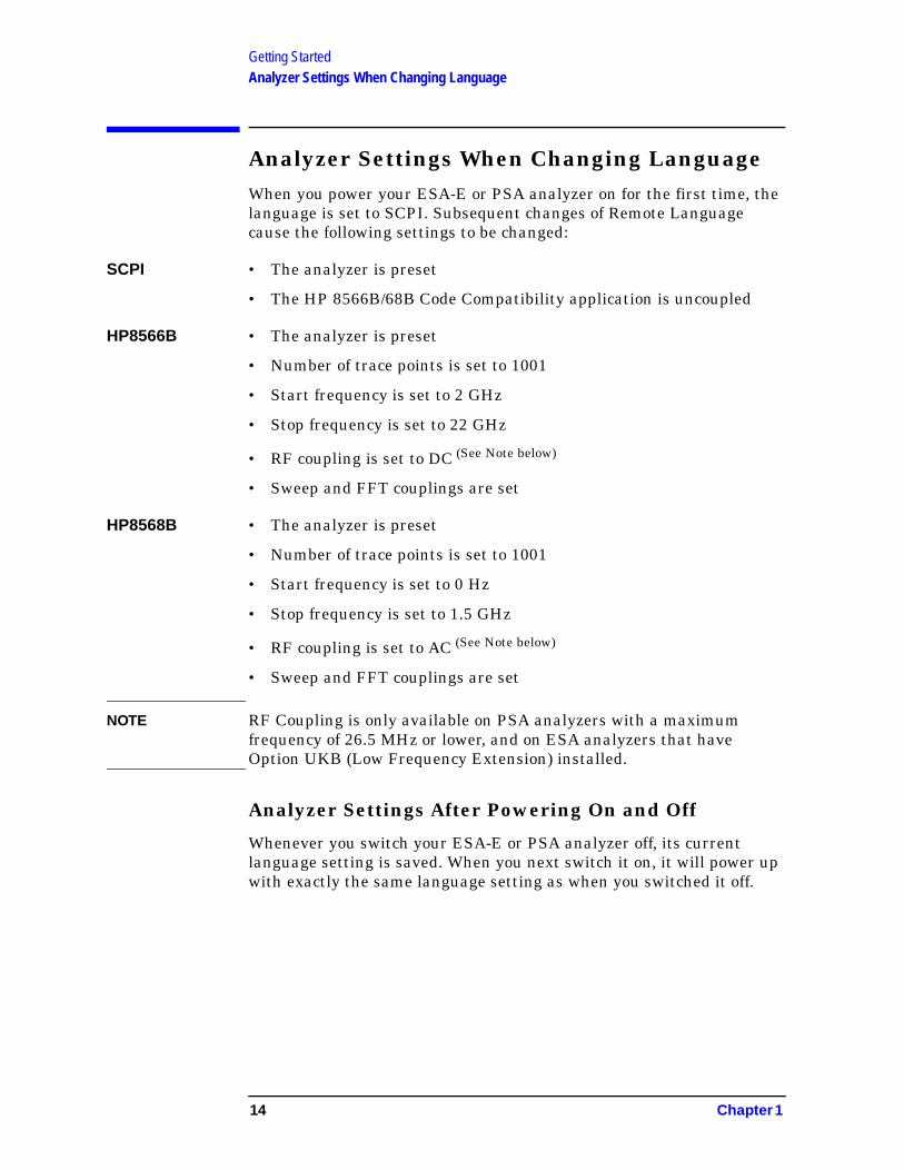
Getting StartedAnalyzer Settings When Changing Language
Analyzer Settings When Changing LanguageWhen you power your ESA-E or PSA analyzer on for the first time, the language is set to SCPI. Subsequent changes of Remote Language cause the following settings to be changed:
SCPI • The analyzer is preset
• The HP 8566B/68B Code Compatibility application is uncoupled
HP8566B • The analyzer is preset
• Number of trace points is set to 1001
• Start frequency is set to 2 GHz
• Stop frequency is set to 22 GHz
• RF coupling is set to DC (See Note below)
• Sweep and FFT couplings are set
HP8568B • The analyzer is preset
• Number of trace points is set to 1001
• Start frequency is set to 0 Hz
• Stop frequency is set to 1.5 GHz
• RF coupling is set to AC (See Note below)
• Sweep and FFT couplings are set
NOTE RF Coupling is only available on PSA analyzers with a maximum frequency of 26.5 MHz or lower, and on ESA analyzers that have Option UKB (Low Frequency Extension) installed.
Analyzer Settings After Powering On and Off
Whenever you switch your ESA-E or PSA analyzer off, its current language setting is saved. When you next switch it on, it will power up with exactly the same language setting as when you switched it off.
14 Chapter 1

Getting StartedThe Configure Remote Lang Screen Menu - ESA-E and PSA Analyzers
The Configure Remote Lang Screen Menu - ESA-E and PSA Analyzers
Configure Remote Lang
This key displays a menu allowing you to select the remote language you wish to use, and to determine how command error messages are stored and displayed.
Language This key allows you to select which remote programming language you wish to use.
SCPI Selects the SCPI remote programming language. This is the default setting after installation.
HP8566B Selects the HP8566B remote programming language and sets the response to the remote programming command ‘ID’ to HP8566B. It also performs an instrument preset, setting Span and Trace Points appropriately.
HP8568B Selects the HP8568B remote programming language and sets the response to the remote programming command ‘ID’ to HP8568B. It also performs an instrument preset, setting Span and Trace Points appropriately.
NOTE Setting the remote language to HP8566B or to HP8568B does not affect the response to the SCPI command ‘*IDN?’ This command will still return the model number and firmware version number of the ESA-E or PSA analyzer.
Command Err This key determines whether or not command errors are displayed on the screen. When set to On, error messages generated by unrecognized commands or command arguments are displayed on the screen. When set to Off, error messages generated by unrecognized commands are not displayed. The current setting is underlined on the key label, and this setting is reversed each time the key is pressed.
NOTE Command Err is set to On after Option 266 has been installed. Thereafter, the latest setting will always be retained, even after a preset has been performed.
Chapter 1 15

Getting StartedThe Configure Remote Lang Screen Menu - ESA-E and PSA Analyzers
Cmd Error Log This key sets command error logging On or Off. When set to On, all error messages are stored in a log file, regardless of whether they have been displayed on the screen. When set to Off, no further command error messages are written to the log file.
The log file is an ASCII text file called LOGFILE.TXT on the C: drive. It has a maximum size of 32 KB. Once it has reached its maximum size, no further error messages will be recorded, but a message will be displayed prompting you to clear the log file. Switching Cmd Error Log to Off does not clear the log file. Only the Clear Command Error Log softkey will clear the error log.
NOTE Command Err Log is set to On after Option 266 has been installed. Thereafter, the latest setting will always be retained, even after a preset has been performed.
Clear Command Error Log
This key allows you to clear all messages from the command error log file LOGFILE.TXT.
16 Chapter 1

Getting StartedDifferences Between Option 266 Commands and the Original HP 8566B/HP 8568B Commands
Differences Between Option 266 Commands and the Original HP 8566B/HP 8568B CommandsThe following table lists commands that behave differently in Agilent Option 266 when compared to the original HP 8566B and HP 8568B analyzers:
Table 1-4 Analyzer Commands That Behave Differently in Option 266
Command HP 8566B / HP 8568B Analyzers
ESA-E Option 266 PSA Option 266
AT Specifies RF input annotation.
Maximum attenuation is limited to 65 dB.
The OA option only returns the current value to the controller. It does not set the active function.
The OA option only returns the current value to the controller. It does not set the active function.
CF Specifies the center frequency.
The OA option only returns the current value to the controller. It does not set the active function.
The OA option only returns the current value to the controller. It does not set the active function.
DET Selects the type of detection - sample, normal, positive peak or negative peak - that is applied to the input signal.
Normal detection is not possible in the ESA, so selection of NRM command option will default to POS (Positive Peak) detection.
Normal detection is possible.
DL Specifies the display line level.
The OA option only returns the current value to the controller. It does not set the active function.
The OA option only returns the current value to the controller. It does not set the active function.
FA Specifies the start frequency value.
The OA option only returns the current start frequency value to the controller. It does not set the active function to the start frequency.
The OA option only returns the current start frequency value to the controller. It does not set the active function to the start frequency.
FB Specifies the stop frequency value.
The OA option only returns the current stop frequency value to the controller. It does not set the active function to the stop frequency.
The OA option only returns the current stop frequency value to the controller. It does not set the active function to the stop frequency.
Chapter 1 17

Getting StartedDifferences Between Option 266 Commands and the Original HP 8566B/HP 8568B Commands
FOFFSET Specifies the frequency offset.
The OA option only returns the current value to the controller. It does not set the active function.
The OA option only returns the current value to the controller. It does not set the active function.
FPKA Performs a fast preselector peak and returns the measured value of the active marker.
Adjusts the centering of the preselector filter to optimize the amplitude accuracy at the active marker frequency.
This functionality is only available in ESA-E series analyzers whose frequency range extends beyond 3 GHz, that is the E4404B, the E4405B, and the E4407B analyzers.
Adjusts the centering of the preselector filter to optimize the amplitude accuracy at the active marker frequency.
This functionality is available in all PSA series analyzers.
I1 [one] Sets RF coupling to DC. This command is not supported on model number E4401B. It is only supported on model number E4407B if Option UKB has been installed.
Note also that the HP 8568B analyzer has two RF ports whereas the ESA only has one.
This command is only supported on PSA analyzers with a frequencyrange up to 26.5 GHz, that is the E4440A, the E4443Aand the E4445A.
Note also that the HP 8568B analyzer has two RF ports whereas the PSA only has one.
I2 [two] Sets RF coupling to AC. This command is not supported on model number E4401B. It is only supported on model number E4407B if Option UKB has been installed.
Note also that the HP 8568B analyzer has two RF ports whereas the ESA only has one.
This command is only supported on PSA analyzers with a frequencyrange up to 26.5 GHz, that is the E4440A, the E4443Aand the E4445A.
Note also that the HP 8568B analyzer has two RF ports whereas the PSA only has one.
KS, Specifies the maximum signal level applied to the input mixer for signals at or below the reference level.
The OA option only returns the current value to the controller. It does not set the active function.
The OA option only returns the current value to the controller. It does not set the active function.
Table 1-4 Analyzer Commands That Behave Differently in Option 266
Command HP 8566B / HP 8568B Analyzers
ESA-E Option 266 PSA Option 266
18 Chapter 1
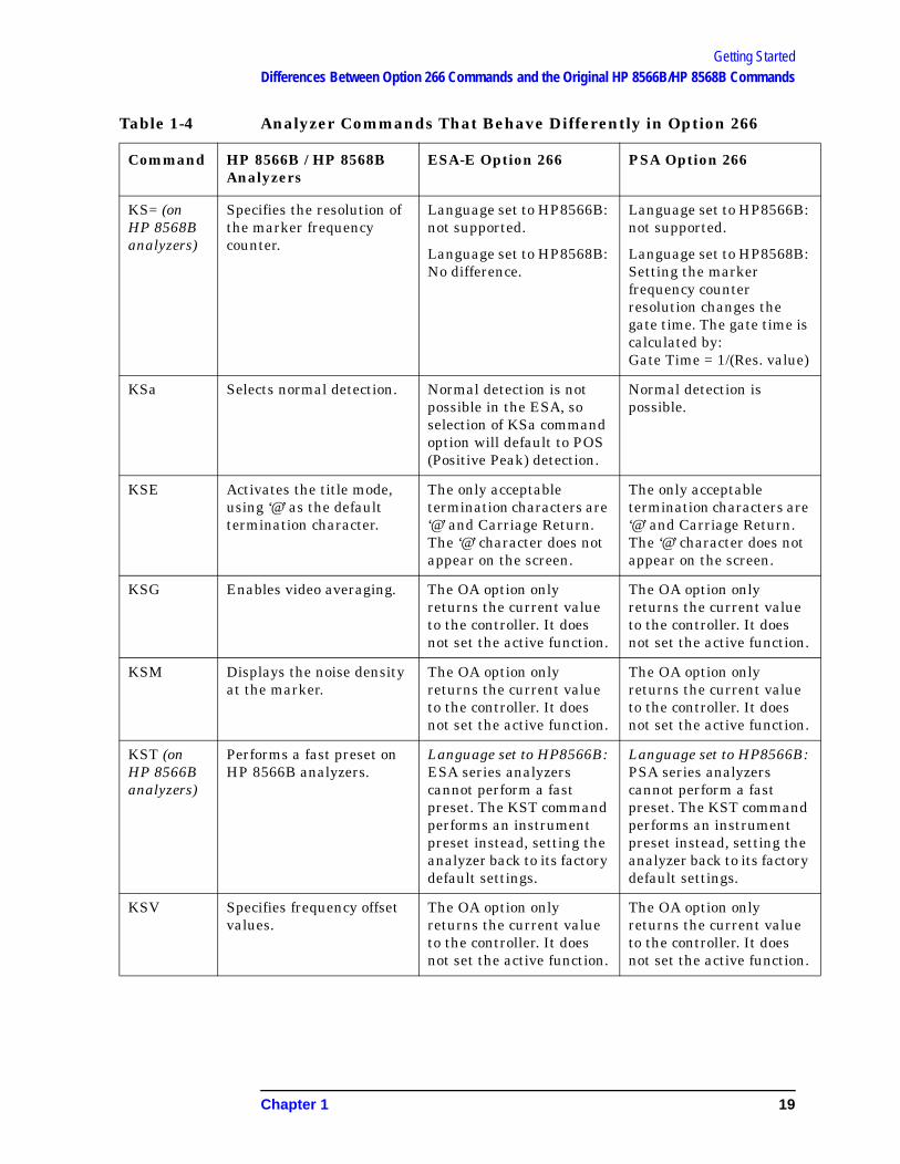
Getting StartedDifferences Between Option 266 Commands and the Original HP 8566B/HP 8568B Commands
KS= (on HP 8568B analyzers)
Specifies the resolution of the marker frequency counter.
Language set to HP8566B: not supported.
Language set to HP8568B: No difference.
Language set to HP8566B:not supported.
Language set to HP8568B:Setting the marker frequency counter resolution changes the gate time. The gate time is calculated by: Gate Time = 1/(Res. value)
KSa Selects normal detection. Normal detection is not possible in the ESA, so selection of KSa command option will default to POS (Positive Peak) detection.
Normal detection is possible.
KSE Activates the title mode, using ‘@’ as the default termination character.
The only acceptable termination characters are ‘@’ and Carriage Return. The ‘@’ character does not appear on the screen.
The only acceptable termination characters are‘@’ and Carriage Return. The ‘@’ character does not appear on the screen.
KSG Enables video averaging. The OA option only returns the current value to the controller. It does not set the active function.
The OA option only returns the current value to the controller. It does not set the active function.
KSM Displays the noise density at the marker.
The OA option only returns the current value to the controller. It does not set the active function.
The OA option only returns the current value to the controller. It does not set the active function.
KST (on HP 8566B analyzers)
Performs a fast preset on HP 8566B analyzers.
Language set to HP8566B: ESA series analyzers cannot perform a fast preset. The KST command performs an instrument preset instead, setting the analyzer back to its factory default settings.
Language set to HP8566B: PSA series analyzers cannot perform a fast preset. The KST command performs an instrument preset instead, setting the analyzer back to its factorydefault settings.
KSV Specifies frequency offset values.
The OA option only returns the current value to the controller. It does not set the active function.
The OA option only returns the current value to the controller. It does not set the active function.
Table 1-4 Analyzer Commands That Behave Differently in Option 266
Command HP 8566B / HP 8568B Analyzers
ESA-E Option 266 PSA Option 266
Chapter 1 19
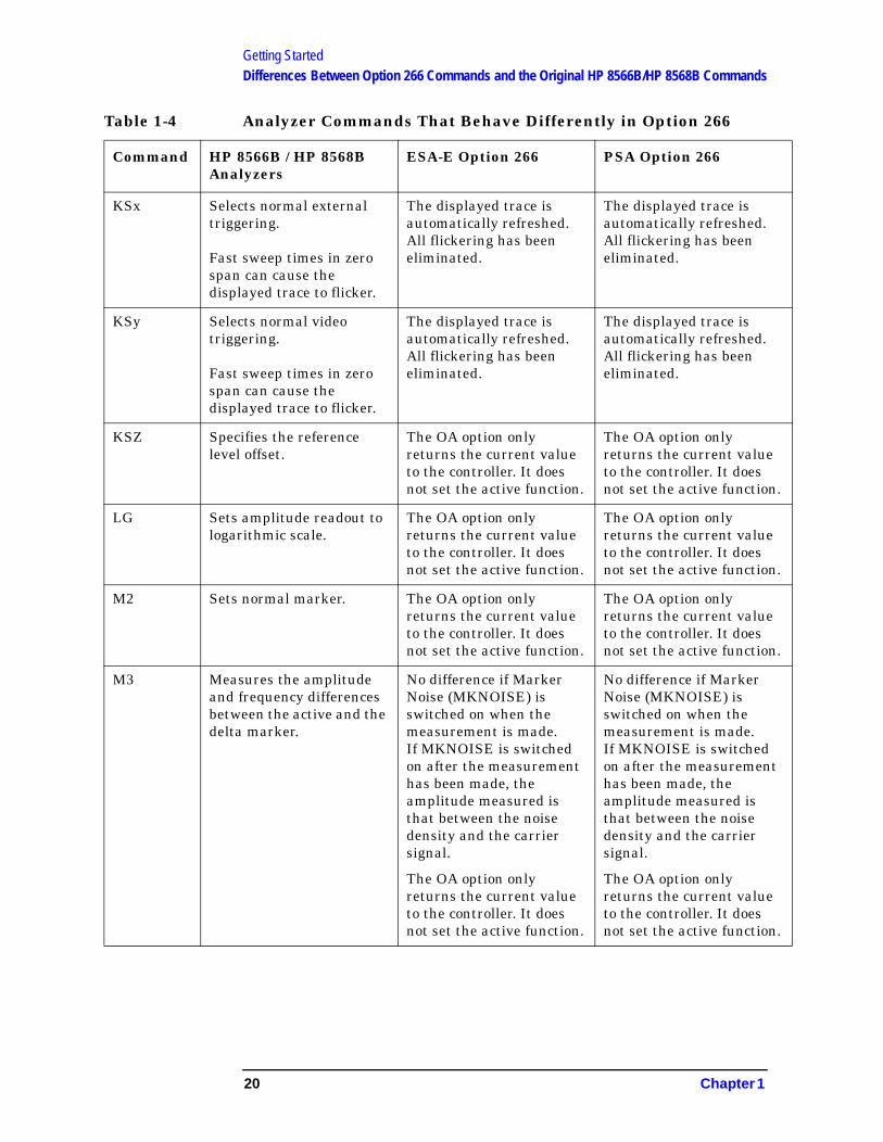
Getting StartedDifferences Between Option 266 Commands and the Original HP 8566B/HP 8568B Commands
KSx Selects normal external triggering.
Fast sweep times in zero span can cause the displayed trace to flicker.
The displayed trace is automatically refreshed. All flickering has been eliminated.
The displayed trace is automatically refreshed. All flickering has been eliminated.
KSy Selects normal video triggering.
Fast sweep times in zero span can cause the displayed trace to flicker.
The displayed trace is automatically refreshed. All flickering has been eliminated.
The displayed trace is automatically refreshed. All flickering has been eliminated.
KSZ Specifies the reference level offset.
The OA option only returns the current value to the controller. It does not set the active function.
The OA option only returns the current value to the controller. It does not set the active function.
LG Sets amplitude readout to logarithmic scale.
The OA option only returns the current value to the controller. It does not set the active function.
The OA option only returns the current value to the controller. It does not set the active function.
M2 Sets normal marker. The OA option only returns the current value to the controller. It does not set the active function.
The OA option only returns the current value to the controller. It does not set the active function.
M3 Measures the amplitude and frequency differences between the active and the delta marker.
No difference if Marker Noise (MKNOISE) is switched on when the measurement is made.If MKNOISE is switched on after the measurement has been made, the amplitude measured is that between the noise density and the carrier signal.
The OA option only returns the current value to the controller. It does not set the active function.
Table 1-4 Analyzer Commands That Behave Differently in Option 266
Command HP 8566B / HP 8568B Analyzers
ESA-E Option 266 PSA Option 266
20 Chapter 1

Getting StartedDifferences Between Option 266 Commands and the Original HP 8566B/HP 8568B Commands
MKA Specifies the amplitude of the active marker in dBm when the active marker is of the fixed or amplitude type.
Only supports the query option.
Only supports the query option.
MKD Measures the amplitude and frequency differences between the active and the delta marker.
No difference if Marker Noise (MKNOISE) is switched on when the measurement is made.If MKNOISE is switched on after the measurement has been made, the amplitude measured is that between the noise density and the carrier signal.
The OA option only returns the current value to the controller. It does not set the active function.
MKFCR Specifies the resolution of the marker frequency counter.
No difference. Setting the marker frequency counter resolution changes the gate time. The gate time is calculated by: Gate Time = 1/(Res. value)
MKREAD Selects the type of trace information that is displayed.
Will not accept the FFT (Fast Fourier Transform) keyword.
WIll not accept the FFT (Fast Fourier Transform) keyword.
MKN Sets normal marker. The OA option only returns the current value to the controller. It does not set the active function.
The OA option only returns the current value to the controller. It does not set the active function.
Table 1-4 Analyzer Commands That Behave Differently in Option 266
Command HP 8566B / HP 8568B Analyzers
ESA-E Option 266 PSA Option 266
Chapter 1 21

Getting StartedDifferences Between Option 266 Commands and the Original HP 8566B/HP 8568B Commands
ML Specifies the maximum signal level applied to the input mixer for signals at or below the reference level.
The mixer level is calculated using the following equation.
Mixer Level = Ref. Level - Attenuation + Ext. Amp Gain.
The external amplifier gain is not preset by doing an IP in case the instrument is measuring a large signal.
The OA option only returns the current value to the controller. It does not set the active function.
OT Output Trace Annotations (Sends 32 character-strings, each of up to 64 characters)
String number 27 (‘dirty marker’ status report) is not supported.
No difference.
PLOT Transfers trace data, graticule parameters and graticule annotation directly to a plotter.
Prints the screen display on a printer rather than transferring data to a plotter.
Prints the screen display on a printer rather than transferring data to a plotter.
PP Peaks preselector. Adjusts the centering of the preselector filter to optimize the amplitude accuracy at the active marker frequency.
This functionality is only available in ESA-E series analyzers whose frequency range extends beyond 3 GHz, that is the E4404B, the E4405B, and the E4407B analyzers.
Adjusts the centering of the preselector filter to optimize the amplitude accuracy at the active marker frequency.
This functionality is available in all PSA series analyzers.
PWRBW Power Bandwidth In the HP 8566B/8568B, the trace stops when the PWRBW command is issued. The trace does not stop in the ESA-E series analyzers.
In the HP 8566B/8568B, the trace stops when the PWRBW command is issued. The trace does not stop in the PSA series analyzers.
Table 1-4 Analyzer Commands That Behave Differently in Option 266
Command HP 8566B / HP 8568B Analyzers
ESA-E Option 266 PSA Option 266
22 Chapter 1

Getting StartedDifferences Between Option 266 Commands and the Original HP 8566B/HP 8568B Commands
R4 Activates the units-key-pressed and illegal-command service requests.
The units-key-pressed service request cannot be supported since front panel interaction is not allowed.
The units-key-pressed service request cannot be supported since front panel interaction is not allowed.
RB Specifies the resolution bandwidth.
Default values may be different to the HP 8566B. Please refer to your ESA-E or PSA User’s Guide for restrictions on the resolution bandwidth range.
The OA option only returns the current value to the controller. It does not set the active function.
Default values may be different to the HP 8566B. Please refer to your ESA-Eor PSA User’s Guide for restrictions on the resolution bandwidth range.
The OA option only returns the current value to the controller. It does not set the active function.
RC Recalls registers containing a set of instrument states.
Recalling the previous state data (RC 7) is not supported.
Recalling the previous state data (RC 7) is not supported.
RCLS Recalls registers containing a set of instrument states.
Recalling the previous state data (RCLS 7) is not supported.
Recalling the previous state data (RCLS 7) is not supported.
REV Returns the firmware revision number.
Returns the build date of your Option 266 (in YYWW format).
Returns the build date of your Option 266 (in YYWWformat).
RL Sets the reference level. The OA option only returns the current value to the controller. It does not set the active function.
The OA option only returns the current value to the controller. It does not set the active function.
ROFFSET Sets the reference level offset.
The OA option only returns the current value to the controller. It does not set the active function.
The OA option only returns the current value to the controller. It does not set the active function.
RQS Sets a bit mask for service requests.
Some differences may be noticed in the value returned by a query.
Some differences may be noticed in the value returned by a query.
SMOOTH Smooths the trace. Some differences in the trace display may be noticed.
Some differences in the trace display may be noticed.
Table 1-4 Analyzer Commands That Behave Differently in Option 266
Command HP 8566B / HP 8568B Analyzers
ESA-E Option 266 PSA Option 266
Chapter 1 23

Getting StartedDifferences Between Option 266 Commands and the Original HP 8566B/HP 8568B Commands
SP Sets the frequency span. The OA option only returns the current value to the controller. It does not set the active function.
The OA option only returns the current value to the controller. It does not set the active function.
SS Sets the center frequency step size.
The OA option only returns the current value to the controller. It does not set the active function.
The OA option only returns the current value to the controller. It does not set the active function.
ST Sets the sweep time. The OA option only returns the current value to the controller. It does not set the active function.
The OA option only returns the current value to the controller. It does not set the active function.
TH Blanks the display of signals below the threshold level.
No change will be noticed in the display.
Note that the PEAKS and MKPK commands can cause all values below the threshold level to be disregarded.
The OA option only returns the current value to the controller. It does not set the active function.
No change will be noticed in the display.
Note that the PEAKS and MKPK commands can cause all values below the threshold level to be disregarded.
The OA option only returns the current value to the controller. It does not set the active function.
VB Specifies the video filter bandwidth.
Default values may be different to the HP 8566B. Please refer to your ESA-E or PSA User’s Guide for restrictions on the video bandwidth range.
The OA option only returns the current value to the controller. It does not set the active function.
Default values may be different to the HP 8566B. Please refer to your ESA-Eor PSA User’s Guide for restrictions on the video bandwidth range.
The OA option only returns the current value to the controller. It does not set the active function.
Table 1-4 Analyzer Commands That Behave Differently in Option 266
Command HP 8566B / HP 8568B Analyzers
ESA-E Option 266 PSA Option 266
24 Chapter 1

Getting StartedDifferences Between Option 266 Commands and the Original HP 8566B/HP 8568B Commands
VAVG Enables video averaging, displaying the original trace in Trace C.
Sweep time remains unchanged.
Only displays the average trace in Trace A.
Sweep time changes.
Differences in how the average is calculated when other settings have changed.
Only displays the average trace in Trace A.
Sweep time changes.
Differences in how the average is calculated whenother settings have changed.
VBO Specifies the ratio of video to resolution bandwidths when coupled.
No change. Some differences may be noticed when VBO of 1 or of -1 is used.
Table 1-4 Analyzer Commands That Behave Differently in Option 266
Command HP 8566B / HP 8568B Analyzers
ESA-E Option 266 PSA Option 266
Chapter 1 25

Getting StartedDifferences Between HP8566B and HP8568B Remote Languages in Option 266
Differences Between HP8566B and HP8568B Remote Languages in Option 266The following table lists Option 266 commands that behave differently in the HP8566B remote language when compared to the HP8568B remote language:
Table 1-5 Option 266 Commands That Behave Differently in the HP8566B and HP8568B Remote Languages
Command HP8566B Remote Language
HP8568B Remote Language
FPKA Valid and supported Invalid - HP 8566B command only
I1 [one] Invalid - HP 8568B command only
Valid and supported (but see Table 1-4 on page 17 and “I1 [one] Set RF Coupling to DC” on page 118)
I2 [two] Invalid - HP 8568B command only
Valid and supported (but see Table 1-4 on page 17) and “I2 [two] Set RF Coupling to AC” on page 120
KSK Valid and supported Valid command on the HP 8568B but unsupported in Option 266
KSN Valid and supported Valid command on the HP 8568B but unsupported in Option 266
KST Valid and supported Valid command on the HP 8568B but unsupported in Option 266
KS= Valid command on the HP 8566B but unsupported in Option 266
Valid and supported
LF Valid and supported Invalid - HP 8566B command only
MC0 [zero] Invalid - HP 8568B command only
Valid and supported
MC1 [one] Invalid - HP 8568B command only
Valid and supported
MKFC Invalid - HP 8568B command only
Valid and supported
26 Chapter 1

Getting StartedDifferences Between HP8566B and HP8568B Remote Languages in Option 266
MKFCR Invalid - HP 8568B command only
Valid and supported
PP Valid and supported Invalid - HP 8566B command only
Table 1-5 Option 266 Commands That Behave Differently in the HP8566B and HP8568B Remote Languages
Command HP8566B Remote Language
HP8568B Remote Language
Chapter 1 27

Getting StartedRunning Software that Requires SCPI Commands
Running Software that Requires SCPI CommandsWhen Remote Language HP8566B or HP8568B has been selected, you will only have access to a very small subset of SCPI commands. If you are not familiar with the SCPI remote programming language, Chapter 5 , “A Brief Introduction to the SCPI Language,” on page 259 contains some useful information.
The SCPI commands available while using the remote language HP8566B or HP8568B are:
• *IDN?
Queries and returns the instrument identification string.
• *RST
Performs an instrument preset.
• :SYSTem:LANGuage SCPI|HP8566B|HP8568B
Sets the current remote language.
This command is only available if you have Option 266 installed on your analyzer.
NOTE Agilent Technologies recommend that you do not repeatedly swap to and from the SCPI language within your programs.
• :SYSTem:LANGuage?
Queries and returns the current remote language.
This command is only available if you have Option 266 installed on your analyzer.
• [:SENSe]:SWEep:TYPE AUTO|SWEep|FFT
Sets the Sweep Type.
• [:SENSe]:SWEep:TYPE?
Queries and returns the Sweep Type.
• [:SENSe]:SWEep:TYPE:AUTO:RULes SPEed|DRANge|DYNamicrange
Sets the auto rule setting for FFT and Sweep Type.
• [:SENSe]:SWEep:TYPE:AUTO:RULes?
Queries and returns the auto rule setting for FFT and Sweep Type.
• :SYSTem:OPTion?
Returns a list of installed options.
28 Chapter 1

Getting StartedRunning Software that Requires SCPI Commands
If Option 266 is installed on your analyzer, the string “266” will appear in the returned string. In the following example, options B7J, 266, and 1DS are all installed.
Example: “B7J,266,1DS”
To return the analyzer to its full ESA or PSA SCPI capability, you must specify the remote language as SCPI.
Chapter 1 29

Getting StartedService and Calibration
Service and CalibrationSince the Performance Verification and Adjustment Software uses the SCPI command language, you will need to set Remote Language to SCPI prior to calibration or service of your Agilent spectrum analyzer.
When your analyzer is returned from an Agilent Technologies service center, you may have to reinstall Option 266. Refer to “Installing/Uninstalling Option 266 - ESA-E Series Analyzers Only” on page 4 or “Installing Option 266 - PSA Series Analyzers Only” on page 9
30 Chapter 1

Getting StartedDocumentation for Option 266
Documentation for Option 266
Spectrum Analyzers with Option 266
When you purchase your ESA-E Series or PSA Series spectrum analyzer with the HP 8566B/68B Code Compatibility (Option 266), you will receive this manual - the HP 8566B/68B Code Compatibility Guide. For information on ESA series analyzers and other related documentation, refer to the ESA web site at http://www.agilent.com/find/esa/. For information on PSA series analyzers and other related documentation, refer to the PSA web site at http://www.agilent.com/find/psa/.
This HP 8566B/68B Code Compatibility Guide is not designed to be a comprehensive guide to all HP 8566B/68B commands. It gives brief descriptions of the supported commands, and highlights important functional or behavioral differences that you should be aware of when transferring existing HP 8566B or HP 8568B code to your ESA-E series or PSA analyzer. For a fuller description of the commands, refer to the HP 8566B or HP 8568B’s Operating and Programming Manual.
Spectrum Analyzer Updates
For the latest information about this instrument, including software upgrades, application information, and product information, please visit the URL listed below.
Updating the Firmware and Software
Updated versions of the Agilent Spectrum Analyzers’ firmware and software will be available via several sources. Information on the latest firmware and software revision can be accessed through the following URL.
NOTE If you have purchased Option 266 as an upgrade, the latest version of the analyzer’s firmware has been included and should be loaded into your instrument before installing the Option 266.
URLs to Obtain Update Information
For ESA analyzers: http://www.agilent.com/find/esa/
For PSA analyzers: http://www.agilent.com/find/psa/
Chapter 1 31

Getting StartedDocumentation for Option 266
32 Chapter 1

2 HP 8566B and HP 8568B Command List
33

HP 8566B and HP 8568B Command ListTable of HP 8566B and HP 8568B Commands
Table of HP 8566B and HP 8568B CommandsThe following table lists all HP 8566B and HP 8568B programming commands, and indicates which are supported in Option 266. Refer to the alphabetical listing of commands in Chapter 4 , “Programming Commands,” on page 61 for more detailed information about each supported command.
34 Chapter 2

HP 8566B and HP 8568B Command ListTable of HP 8566B and HP 8568B Commands
Table 2-1 Alphanumeric List of All HP 8566B/HP 8568B Commands and Their Option 266 Support
HP8566B/ HP8568B
Command
Supported in Option 266?
Command Description Note
A1 [one] Yes Clear write of Trace A See page 65 for more details
A2 [two] Yes Maximum hold for Trace A See page 66 for more details
A3 [three] Yes View Trace A See page 67 for more details
A4 [four] Yes Blank Trace A See page 68 for more details
ABS No Puts the absolute value of the source into the destination.
Returns error - "CMD NOT SUPPORTED"
ADD No Operand 1 + Operand 2 into destination
Returns error - "CMD NOT SUPPORTED"
AMB Yes A minus B into A See page 69 for more details
AMBPL Yes (A minus B) + DL into A See page 70 for more details
ANNOT Yes Turns the Annotation ON or OFF Not supported on PSA See page 71 for more details
APB Yes A plus B into A (Adds trace A and B point by point and sends results to A)
See page 72 for more details
AT Yes Specifies input attenuation See page 73 for more details
AUNITS Yes Specifies amplitude units for input, output and display
See page 75 for more details
AVG No Operand is averaged into destination
Returns error - "CMD NOT SUPPORTED"
AXB Yes Exchange A and B See page 76 for more details
B1 [one] Yes Clear write of Trace B See page 77 for more details
Chapter 2 35

HP 8566B and HP 8568B Command ListTable of HP 8566B and HP 8568B Commands
B2 [two] Yes Maximum hold for Trace B See page 78 for more details
B3 [three] Yes View Trace B See page 79 for more details
B4 [four] Yes Blank Trace B See page 80 for more details
BL Yes Trace B minus Display Line into B See page 81 for more details
BLANK Yes Blanks traces and stops the sweep. Trace is not updated
See page 82 for more details
BML Yes Trace B minus Display Line into B See page 83 for more details
BRD No Bus Read (Reads a 2 byte word at the internal input/output) (This is a service diagnostic function only)
Returns error - "CMD NOT SUPPORTED"
BTC Yes Transfers trace B to trace C See page 84 for more details
BWR No Bus Write Word (Writes a 2 byte word at the internal input/output) (This is a service diagnostic function only)
Returns error - "CMD NOT SUPPORTED"
BXC Yes Exchanges traces B and C point by point
See page 85 for more details
C1 [one] Yes Trace A minus Trace B into Trace A On
See page 86 for more details
C2 [two] Yes Trace A minus Trace B into Trace A Off
See page 87 for more details
CA Yes Couple Attenuator (Resets the attenuation value so that a continuous wave signal displayed at the reference level will yield the maximum mixer level (see ML command) at the mixer input)
See page 88 for more details
CF Yes Center Frequency See page 89 for more details
Table 2-1 Alphanumeric List of All HP 8566B/HP 8568B Commands and Their Option 266 Support
HP8566B/ HP8568B
Command
Supported in Option 266?
Command Description Note
36 Chapter 2

HP 8566B and HP 8568B Command ListTable of HP 8566B and HP 8568B Commands
CLRAVG Yes Clear Average See page 91 for more details
CLRW Yes Enables the Clear-Write Mode which continuously displays any signals present at the analyzer input
See page 92 for more details
CNVLOSS No Selects the reference level offset to amplitude calibrate the display for a mixer with a given loss
Returns error - "CMD NOT SUPPORTED"
COMPRESS No Compresses trace source to fit trace destination
Returns error - "CMD NOT SUPPORTED"
CONCAT No Concatenates operands and sends new trace to destination
Returns error - "CMD NOT SUPPORTED"
CONTS Yes Sets the analyzer to continuous sweep mode
See page 93 for more details
CR Yes Couples the resolution bandwidth with the video bandwidth and sweep time
See page 94 for more details
CS Yes Couples the center frequency step size to the span width (Step Size = 0.1 x Span Width) (1 major graticule division)
See page 95 for more details
CT Yes Couples the sweep time with the resolution and video bandwidths
See page 96 for more details
CTA No Converts the operand values from display units to absolute amplitude units
Returns error - "CMD NOT SUPPORTED"
CTM No Converts the operand values to vertical display units
Returns error - "CMD NOT SUPPORTED"
CV Yes Couples video bandwidth with the resolution bandwidth and sweep time
See page 97 for more details
D1 [one] No Sets the display to normal size, selected with IP.
Returns error - "CMD NOT SUPPORTED"
D2 [two] No Sets the display to full CRT size. Returns error - "CMD NOT SUPPORTED"
Table 2-1 Alphanumeric List of All HP 8566B/HP 8568B Commands and Their Option 266 Support
HP8566B/ HP8568B
Command
Supported in Option 266?
Command Description Note
Chapter 2 37

HP 8566B and HP 8568B Command ListTable of HP 8566B and HP 8568B Commands
DA Yes Display memory address Only DA 1, DA 1025 and DA 3073 are supported
DD No Writes two 8 bytes (binary) into the current or specified memory address & advances address by 1
Returns error - "CMD NOT SUPPORTED"
DET Yes Input Detector See page 99 for more details
DISPOSE No Clears specified operands (Trace Label, Var Identifier, Function Identifier, Key Number)
Returns error - "CMD NOT SUPPORTED"
DIV No Divide operand 1 by operand 2, point by point
Returns error - "CMD NOT SUPPORTED"
DL Yes Display Line Level (dBm) See page 101 for more details
DLE Yes Enable or disables the Display Line See page 102 for more details
DONE Yes A synchronizing function - sends a ’1’ to the controller after the command line is executed
See page 103 for more details
DR No Display Read - sends the contents of the current display address to the controller
Returns error - "CMD NOT SUPPORTED"
DSPLY No Displays the value of a variable Returns error - "CMD NOT SUPPORTED"
DT No Define Terminator Returns error - "CMD NOT SUPPORTED"
DW No Display Write - sends a decimal value from the controller to the display memory address
Returns error - "CMD NOT SUPPORTED"
D3 [three] No Sets the display to expanded size. Returns error - "CMD NOT SUPPORTED"
E1 [one] Yes Moves the active marker to the maximum signal detected.
See page 104 for more details
E2 [two] Yes Moves the active marker frequency into the center frequency.
See page 105 for more details
Table 2-1 Alphanumeric List of All HP 8566B/HP 8568B Commands and Their Option 266 Support
HP8566B/ HP8568B
Command
Supported in Option 266?
Command Description Note
38 Chapter 2

HP 8566B and HP 8568B Command ListTable of HP 8566B and HP 8568B Commands
E3 [three] Yes Moves the active marker frequency or the delta marker frequency into the center frequency step size.
See page 106 for more details
E4 [four] Yes Moves the active marker to the reference level.
See page 107 for more details
EE No Enables front panel number entry Returns error - "CMD NOT SUPPORTED"
EK No Enables the data knob Returns error - "CMD NOT SUPPORTED"
ELSE No Conditional command used in conjunction with an IF command
Returns error - "CMD NOT SUPPORTED"
EM No Erase Trace C memory addresses 3072 through 4095
Returns error - "CMD NOT SUPPORTED"
ENDIF No Finishing off an IF command Returns error - "CMD NOT SUPPORTED"
ENTER No Enter from GPIB, allows a function definition to enter data from the GPIB port.
Returns error - "CMD NOT SUPPORTED"
ERASE No All user memory and save/recall registers are erased.
Returns error - "CMD NOT SUPPORTED"
ERR Yes Returns a list of all error codes. See page 108 for more details
EX Yes Exchange Trace A and Trace B See page 109 for more details
EXP No Exponential (10 raised to the power of (operand/scaling factor), to destination)
Returns error - "CMD NOT SUPPORTED"
EXTMXR No Presets the External Mixing Mode (setting the frequency range from 18.0 GHz to 26.5 GHz)
Returns error - "CMD NOT SUPPORTED"
FA Yes Specifies the start frequency value See page 110 for more details
FB Yes Specifies the stop frequency value See page 111 for more details
Table 2-1 Alphanumeric List of All HP 8566B/HP 8568B Commands and Their Option 266 Support
HP8566B/ HP8568B
Command
Supported in Option 266?
Command Description Note
Chapter 2 39

HP 8566B and HP 8568B Command ListTable of HP 8566B and HP 8568B Commands
FFT No Fast Fourier Transform on a trace array (contains logged magnitude components only)
Returns error - "CMD NOT SUPPORTED"
FFTKNL No 16 bit Discrete Fourier Transform on specified traces, overlaying them with the results.
Returns error - "CMD NOT SUPPORTED"
FOFFSET Yes Frequency Offset See page 112 for more details
FPKA Yes Fast Preselector Peak See page 114 for more details
FS Yes Full Span See page 115 for more details
FULBAND No Sets the start & stop frequencies for the analyzer external mixing bands
Returns error - "CMD NOT SUPPORTED"
FUNCDEF No Function Define - defines a program routine as a function label
Returns error - "CMD NOT SUPPORTED"
GR No Plots GPIB inputs as graphs (in trace modes of application only)
Returns error - "CMD NOT SUPPORTED"
GRAT Yes Graticule on and off See page 117 for more details
HD No Holds data entry (Disables) Returns error - "CMD NOT SUPPORTED"
HNLOCK No Harmonic lock (LO harmonic frequency lock)
Returns error - "CMD NOT SUPPORTED"
HNUNLK No Harmonic Bank Unlock (tune over the whole frequency range)
Returns error - "CMD NOT SUPPORTED"
I1 [one] Yes Set RF coupling to DC. Not supported on all ESAs.Not supported on PSAs where the maximum frequency range is greater than 26.5 GHz. See page 118 for more details
Table 2-1 Alphanumeric List of All HP 8566B/HP 8568B Commands and Their Option 266 Support
HP8566B/ HP8568B
Command
Supported in Option 266?
Command Description Note
40 Chapter 2

HP 8566B and HP 8568B Command ListTable of HP 8566B and HP 8568B Commands
I2 [two] Yes Set RF coupling to AC. Not supported on all ESAs.Not supported on PSAs where the maximum frequency range is greater than 26.5 GHz. See page 120 for more details
IB No Input to trace B memory Returns error - "CMD NOT SUPPORTED"
ID Yes Instrument Identity (Identify) See page 122 for more details
IDSTAT No Signal Identifier Status (Returns 1,0,-1)
Returns error - "CMD NOT SUPPORTED"
IF No Conditional command used in conjunction with other commands
Returns error - "CMD NOT SUPPORTED"
IFTKNL No 16 bit Discrete Fourier Transform on specified traces, overlaying them with the results multiplied by N (length of each trace).
Returns error - "CMD NOT SUPPORTED"
INT No The greatest integer which is less than or equal to the source real is stored in the destination
Returns error - "CMD NOT SUPPORTED"
IP Yes Sets instrument parameters to preset values. (deactivates the display line)
See page 123 for more details
KEYDEF No Assigns function label or command list to soft key number
Returns error - "CMD NOT SUPPORTED"
KEYEXC No Executes specified soft key Returns error - "CMD NOT SUPPORTED"
KS# No Turns off the YIG-tuned mixed (YTX) self heating correction factor
Returns error - "CMD NOT SUPPORTED"
KS( No Lock registers Returns error - "CMD NOT SUPPORTED"
KS) No Unlock registers Returns error - "CMD NOT SUPPORTED"
Table 2-1 Alphanumeric List of All HP 8566B/HP 8568B Commands and Their Option 266 Support
HP8566B/ HP8568B
Command
Supported in Option 266?
Command Description Note
Chapter 2 41

HP 8566B and HP 8568B Command ListTable of HP 8566B and HP 8568B Commands
KS, Yes Specifies the maximum signal level that is applied to the input mixer
Does not support the use of no parameters
KS/ No Manual Preselector Tracking Returns error - "CMD NOT SUPPORTED"
KS< No Specifies the preamp gain for signal input 1.
Returns error - "CMD NOT SUPPORTED"
KS=(HP 8566B only)
No Reinstate Automatic Preselector Tracking
See page 125 for more details
KS=(HP 8568B only)
Yes Specifies the resolution of the marker frequency counter
See page 125 for more details
KS> No Specifies the preamp gain for signal input 2.
Returns error - "CMD NOT SUPPORTED"
KS| No Writes the instruction word or data value into the specified memory address
Returns error - "CMD NOT SUPPORTED"
KS123 No Reads display memory Returns error - "CMD NOT SUPPORTED"
KS125 No Writes to display memory Returns error - "CMD NOT SUPPORTED"
KS126 No Reads every nth value in the memory
Returns error - "CMD NOT SUPPORTED"
KS127 No Writes to display memory Returns error - "CMD NOT SUPPORTED"
KS39 No Writes to display memory Returns error - "CMD NOT SUPPORTED"
KS43 No Sends Service Request ‘102’. This queries whether the analyzer current frequency band has been exceeded (Frequency Limit SRQ)
Returns error - "CMD NOT SUPPORTED"
KS91 No Read amplitude error Returns error - "CMD NOT SUPPORTED"
KS92 No Write in display units Returns error - "CMD NOT SUPPORTED"
Table 2-1 Alphanumeric List of All HP 8566B/HP 8568B Commands and Their Option 266 Support
HP8566B/ HP8568B
Command
Supported in Option 266?
Command Description Note
42 Chapter 2

HP 8566B and HP 8568B Command ListTable of HP 8566B and HP 8568B Commands
KS94 No Read LO harmonic number Returns error - "CMD NOT SUPPORTED"
KSA Yes Sets amplitude units to dBm See page 126 for more details
KSa Yes Normal input detection for displaying trace information
See page 128 for more details
KSB Yes Sets amplitude units to dBmV See page 128 for more details
KSb Yes Positive peak input detection See page 129 for more details
KSC Yes Sets amplitude units to dBuV See page 130 for more details
KSc Yes Trace A + Trace B into Trace A (APB)
See page 131 for more details
KSD Yes Sets amplitude units to Volts See page 132 for more details
KSd Yes Negative peak detection See page 133 for more details
KSE Yes Activates the Title Mode See page 134 for more details
KSe Yes Sample detection See page 135 for more details
KSF No 8566B Shift YTO: Removes the IF offset from the YIG-tuned oscillator (Service Diagnostic aid).8568B: Measures the sweep time.
Returns error - "CMD NOT SUPPORTED"
KSf No Protects instrument state configuration during power loss
Returns error - "CMD NOT SUPPORTED"
KSG Yes Video averaging On See page 136 for more details
KSg Yes CRT beam off See page 137 for more details
KSH Yes Video averaging Off See page 138 for more details
Table 2-1 Alphanumeric List of All HP 8566B/HP 8568B Commands and Their Option 266 Support
HP8566B/ HP8568B
Command
Supported in Option 266?
Command Description Note
Chapter 2 43

HP 8566B and HP 8568B Command ListTable of HP 8566B and HP 8568B Commands
KSh Yes CRT beam on See page 139 for more details
KSI No Extends reference level range to maximum limits (-139.9 dBm to +60 dBm)
Returns error - "CMD NOT SUPPORTED"
KSi Yes Exchange Trace B and Trace C (BXC)
See page 140 for more details
KSJ No DAC Control Returns error - "CMD NOT SUPPORTED"
KSj Yes View Trace C See page 141 for more details
KSK Yes Marker to Next Peak of lower amplitude
See page 142 for more details
KSk Yes Blank Trace C See page 143 for more details
KSL Yes Marker noise Off (disables the noise density function which displays the RMS noise density)
See page 144 for more details
KSl Yes Transfer Trace B to Trace C (BTC) See page 145 for more details
KSM Yes Marker noise On See page 146 for more details
KSm Yes Graticule Off See page 148 for more details
KSN Yes Marker minimum value detected See page 149 for more details
KSn Yes Graticule On See page 150 for more details
KSO Yes Marker span See page 151 for more details
KSo Yes Annotation Off See page 152 for more details
KSP No GPIB address Returns error - "CMD NOT SUPPORTED"
Table 2-1 Alphanumeric List of All HP 8566B/HP 8568B Commands and Their Option 266 Support
HP8566B/ HP8568B
Command
Supported in Option 266?
Command Description Note
44 Chapter 2

HP 8566B and HP 8568B Command ListTable of HP 8566B and HP 8568B Commands
KSp Yes Annotation On See page 153 for more details
KSQ No Band unlock Returns error - "CMD NOT SUPPORTED"
KSq No Step gain Off Returns error - "CMD NOT SUPPORTED"
KSR No Diagnostics On Returns error - "CMD NOT SUPPORTED"
KSr No Service Request 102 to the controller Returns error - "CMD NOT SUPPORTED"
KSS No Fast GPIB remote operation Returns error - "CMD NOT SUPPORTED"
KST (HP 8566B only)
Yes Fast Preset 2-22 GHz Remote language HP8566B only. See page 154 for more details
KST (HP 8568B only)
No Shifts second LO down Remote language HP8568B. Returns error - "CMD NOT SUPPORTED"
KSt No Harmonic lock Returns error - "CMD NOT SUPPORTED"
KSU No Fast preset external mixer Returns error - "CMD NOT SUPPORTED"
KSu No Marker stop Returns error - "CMD NOT SUPPORTED"
KSV Yes Frequency offset See page 155 for more details
KSv No External mixer signal identifier Returns error - "CMD NOT SUPPORTED"
KSW No Activate error correction routine Returns error - "CMD NOT SUPPORTED"
KSw No Displays correction data Returns error - "CMD NOT SUPPORTED"
KSX No Correction factor On (incorporates them into measurements)
Returns error - "CMD NOT SUPPORTED"
Table 2-1 Alphanumeric List of All HP 8566B/HP 8568B Commands and Their Option 266 Support
HP8566B/ HP8568B
Command
Supported in Option 266?
Command Description Note
Chapter 2 45

HP 8566B and HP 8568B Command ListTable of HP 8566B and HP 8568B Commands
KSx Yes External trigger mode See page 156 for more details
KSY No Correction factors Off Returns error - "CMD NOT SUPPORTED"
KSy Yes Video trigger mode See page 157 for more details
KSZ Yes Reference level offset See page 158 for more details
KSz No Storage address Returns error - "CMD NOT SUPPORTED"
L0 [zero] Yes Disables the display line See page 159 for more details
LB No Writes text label Returns error - "CMD NOT SUPPORTED"
LF(HP 8566B only)
Yes Preset 0 - 2.5 GHz See page 160 for more details
LG Yes Specifies the vertical graticule divisions as logarithmic units without changing the reference level (Log Scale)
See page 161 for more details
LL No Sends a voltage to the rear panel RECORDER OUTPUTS (Lower Left)
Returns error - "CMD NOT SUPPORTED"
LN Yes Linear Scale (scales the amplitude proportional to input voltage)
See page 162 for more details
LOG No Log. (Operand 1 x Scaling Factor into Destination)
Returns error - "CMD NOT SUPPORTED"
LOLIMOFF No Local oscillator limit off Returns error - "CMD NOT SUPPORTED"
M1 [one] Yes Marker Off See page 163 for more details
M2 [two] Yes Marker Normal See page 164 for more details
M3 [three] Yes Delta Marker See page 165 for more details
Table 2-1 Alphanumeric List of All HP 8566B/HP 8568B Commands and Their Option 266 Support
HP8566B/ HP8568B
Command
Supported in Option 266?
Command Description Note
46 Chapter 2

HP 8566B and HP 8568B Command ListTable of HP 8566B and HP 8568B Commands
M4 [four] No Marker Zoom Returns error - "CMD NOT SUPPORTED"
MA Yes Returns Marker Amplitude See page 167 for more details
MBRD No Processor Memory Block Read Returns error - "CMD NOT SUPPORTED"
MBWR No Processor Memory Block Write Returns error - "CMD NOT SUPPORTED"
MC0 [zero](HP 8568B only)
Yes Turns off the marker frequency counter.
See page 168 for more details
MC1 [one](HP 8568B only)
Yes Turns on the marker frequency counter.
See page 169 for more details
MDS Yes Measurement Data Size See page 170 for more details
MDU No Measurement Data Units Returns error - "CMD NOT SUPPORTED"
MEAN Yes Returns the mean value of the trace, in display units
See page 171 for more details
MEM No Returns the amount of unused memory available for user-defined functions
Returns error - "CMD NOT SUPPORTED"
MERGE No Moves a portion of the source trace into the destination trace starting at a predetermined position.
Returns error - "CMD NOT SUPPORTED"
MF Yes Marker Frequency output See page 172 for more details
MIN No Compares operand 1 and 2 and returns the minimum value
Returns error - "CMD NOT SUPPORTED"
MINPOS Yes Returns a value that is the x position of the minimum value in the given trace.
See page 173 for more details
MIRROR No Takes the mirror image of the source trace and moves it into a destination trace.
Returns error - "CMD NOT SUPPORTED"
Table 2-1 Alphanumeric List of All HP 8566B/HP 8568B Commands and Their Option 266 Support
HP8566B/ HP8568B
Command
Supported in Option 266?
Command Description Note
Chapter 2 47

HP 8566B and HP 8568B Command ListTable of HP 8566B and HP 8568B Commands
MKA Yes Marker amplitude (in current amplitude units)
See page 174 for more details
MKACT Yes Marker Active See page 175 for more details
MKCF Yes Marker to Center Frequency See page 176 for more details
MKCONT No Marker Continue (Resumes the sweep)
Returns error - "CMD NOT SUPPORTED"
MKD Yes Marker Delta (Computes the frequency and amplitude difference of the active marker and the reference marker)
See page 177 for more details
MKF Yes Marker Frequency See page 179 for more details
MKFC(HP 8568B only)
Yes Marker Frequency Counter See page 180 for more details
MKFCR(HP 8568B only)
Yes Marker Frequency Counter Resolution
See page 181 for more details
MKMIN Yes Marker minimum See page 182 for more details
MKN Yes Marker Normal (Moves the active marker to the specified frequency)
See page 183 for more details
MKNOISE Yes Marker Noise (RMS noise density at the marker)
See page 184 for more details
MKOFF Yes Marker Off See page 186 for more details
MKP Yes Horizontal Marker Position (in Display Units)
See page 187 for more details
MKPAUSE No Marker Pause (pauses the sweep for the duration of the delay period)
Returns error - "CMD NOT SUPPORTED"
MKPK Yes Marker Peak See page 188 for more details
Table 2-1 Alphanumeric List of All HP 8566B/HP 8568B Commands and Their Option 266 Support
HP8566B/ HP8568B
Command
Supported in Option 266?
Command Description Note
48 Chapter 2

HP 8566B and HP 8568B Command ListTable of HP 8566B and HP 8568B Commands
MKPX Yes Marker Peak Excursion (specifies the minimum signal excursion for the analyzer internal peak identification routine)
See page 190 for more details
MKREAD Yes Marker Readout See page 191 for more details
MKRL Yes Marker to reference level See page 193 for more details
MKSP Yes Marker Span See page 194 for more details
MKSS Yes Delta Marker Step Size See page 195 for more details
MKSTOP No Marker stop (Stops the sweep) Returns error - "CMD NOT SUPPORTED"
MKTRACE Yes Marker Trace specifies the marker to operate on data in Trace A, B, or C
See page 196 for more details
MKTRACK Yes Marker Track (keeps the active marker at the center of the display)
See page 197 for more details
MKTYPE No Marker Type Returns error - "CMD NOT SUPPORTED"
ML Yes Mixer Level (specifies the maximum signal level that is applied to the input mixer for a signal that is equal to or below the reference level)
See page 198 for more details
MOD No Remainder of the division of source 1 by source 2 is stored in the destination.
Returns error - "CMD NOT SUPPORTED"
MOV No Moves the operand to the destination
Returns error - "CMD NOT SUPPORTED"
MPY No Multiply Returns error - "CMD NOT SUPPORTED"
MRD No Memory Read Word Returns error - "CMD NOT SUPPORTED"
MRDB No Memory Read Byte Returns error - "CMD NOT SUPPORTED"
Table 2-1 Alphanumeric List of All HP 8566B/HP 8568B Commands and Their Option 266 Support
HP8566B/ HP8568B
Command
Supported in Option 266?
Command Description Note
Chapter 2 49

HP 8566B and HP 8568B Command ListTable of HP 8566B and HP 8568B Commands
MT0 [zero] Yes Marker Tracking Mode Off See page 200 for more details
MT1 [one] Yes Marker Tracking Mode On See page 201 for more details
MWR No Memory Write Word Returns error - "CMD NOT SUPPORTED"
MWRB No Memory Write Byte Returns error - "CMD NOT SUPPORTED"
MXM No Maximum Returns error - "CMD NOT SUPPORTED"
MXMH Yes Maximum Hold (updates each trace element with the maximum level detected while the trace is active and displayed)
See page 202 for more details
NSTART No Start Harmonic (for signal identification routine - SIGID)
Returns error - "CMD NOT SUPPORTED"
NSTOP No Stop Harmonic (for signal identification routine - SIGID)
Returns error - "CMD NOT SUPPORTED"
O1 [one] Yes Selects display units data format. See page 203 for more details
O2 [two] Yes Selects two 8-bit byte data format. See page 204 for more details
O3 [three] Yes Selects real amplitude units format. See page 205 for more details
O4 [four] Yes Selects one 8-bit byte data format. See page 206 for more details
OL No Output Learn String (transmits information to the controller that describes the state of the analyzer)
Returns error - "CMD NOT SUPPORTED"
ONEOS No On end of sweep Returns error - "CMD NOT SUPPORTED"
ONSWP No On Sweep Returns error - "CMD NOT SUPPORTED"
OP No Output Parameter Returns error - "CMD NOT SUPPORTED"
Table 2-1 Alphanumeric List of All HP 8566B/HP 8568B Commands and Their Option 266 Support
HP8566B/ HP8568B
Command
Supported in Option 266?
Command Description Note
50 Chapter 2

HP 8566B and HP 8568B Command ListTable of HP 8566B and HP 8568B Commands
OT Yes Output Trace Annotations (Sends 32 character-strings, each of up to 64 characters)
See page 207 for more details
OUTPUT No Output is provided for sending data to the GPIB port from a function definition.
Returns error - "CMD NOT SUPPORTED"
PA No Plot Absolute (Vector Location) Returns error - "CMD NOT SUPPORTED"
PD No Pen Down (draws one or more vectors)
Returns error - "CMD NOT SUPPORTED"
PDA No Probability Distribution Amplitude (loads the destination trace according to the pattern of amplitude values in the source trace)
Returns error - "CMD NOT SUPPORTED"
PDF No Probability Distribution in Frequency (elements of the source trace that are above the threshold value cause corresponding elements in the destination trace to be increased in amplitude by one display unit.)
Returns error - "CMD NOT SUPPORTED"
PEAKS Yes Sorts signal peaks into frequency or amplitude order, sends results to destination trace.
See page 208 for more details
PKPOS Yes Returns a value that is the x position of the maximum value in the given trace.
See page 209 for more details
PLOT Yes Plot See page 210 for more details.
PP Yes Preselector Peak See page 211 for more details
PR No Plot Relative Returns error - "CMD NOT SUPPORTED"
PS No Skip Page Returns error - "CMD NOT SUPPORTED"
PU No Pen Up (Blanks the CRT beam) Returns error - "CMD NOT SUPPORTED"
Table 2-1 Alphanumeric List of All HP 8566B/HP 8568B Commands and Their Option 266 Support
HP8566B/ HP8568B
Command
Supported in Option 266?
Command Description Note
Chapter 2 51

HP 8566B and HP 8568B Command ListTable of HP 8566B and HP 8568B Commands
PWRBW Yes Power Bandwidth (first computes the total power of a trace, and then returns the bandwidth equal to a percentage of the total power.)
See page 212 for more details
R1 [one] Yes Resets service request 140 See page 213 for more details
R2 [two] Yes Allows service request 140 & 104 See page 214 for more details
R3 [three] Yes Allows service request 140 & 110 See page 215 for more details
R4 [four] Yes Allows service request 140 & 102 See page 216 for more details
RB Yes Resolution Bandwidth See page 217 for more details
RC Yes Recalls State Register See page 218 for more details
RCLS Yes Recalls State Register See page 219 for more details
REPEAT No Repeat... Until (conditional programming)
Returns error - "CMD NOT SUPPORTED"
REV Yes Revision (returns the firmware revision and the Agilent Date Code)
See page 220 for more details
RL Yes Reference Level (amplitude value of the top CRT Graticule line)
See page 221 for more details
RMS Yes Root Mean Square See page 223 for more details
ROFFSET Yes Reference Level Offset See page 224 for more details
RQS Yes SRQ mask (sets a bit mask for the service request commands)
See page 225 for more details
S1 [one] Yes Sets the analyzer to continuous sweep mode
See page 226 for more details
S2 [two] Yes Sets the analyzer to single sweep mode
See page 227 for more details
Table 2-1 Alphanumeric List of All HP 8566B/HP 8568B Commands and Their Option 266 Support
HP8566B/ HP8568B
Command
Supported in Option 266?
Command Description Note
52 Chapter 2

HP 8566B and HP 8568B Command ListTable of HP 8566B and HP 8568B Commands
SAVES Yes Saves the current state of the analyzer in the specified register
See page 228 for more details
SIGDEL No Specifies the maximum amplitude difference allowed between a signal and its image for the pair to be recognized by the signal identification routine (Default units are dB)
Returns error - "CMD NOT SUPPORTED"
SIGID No Identifies signals for external mixing frequency bands
Returns error - "CMD NOT SUPPORTED"
SMOOTH Yes Smooths the given trace over a specified number of points
See page 229 for more details
SNGLS Yes Sets the analyzer to single sweep mode
See page 230 for more details
SP Yes Frequency Span See page 231 for more details
SQR No Square Root of the source trace amplitude, point by point
Returns error - "CMD NOT SUPPORTED"
SRQ Yes Service Request to the controller (User defined)
See page 233 for more details
SS Yes Center Frequency step size See page 234 for more details
ST Yes Sweep Time See page 235 for more details
STDEV Yes Returns standard deviation of trace amplitude in display units
See page 236 for more details
SUB No Subtract Returns error - "CMD NOT SUPPORTED"
SUM No Returns sum of trace element amplitudes in display units
Returns error - "CMD NOT SUPPORTED"
SUMSQR No Squares trace element amplitudes and returns their sum
Returns error - "CMD NOT SUPPORTED"
SV Yes Saves State See page 237 for more details
SW No Skip to next control instruction Returns error - "CMD NOT SUPPORTED"
Table 2-1 Alphanumeric List of All HP 8566B/HP 8568B Commands and Their Option 266 Support
HP8566B/ HP8568B
Command
Supported in Option 266?
Command Description Note
Chapter 2 53

HP 8566B and HP 8568B Command ListTable of HP 8566B and HP 8568B Commands
T0 [zero] No Turns the threshold level off. Returns error - "CMD NOT SUPPORTED"
T1 [one] Yes Sets the analyzer sweep to Free Run Trigger Mode
See page 238 for more details
T2 [two] Yes Line Trigger Mode See page 239 for more details
T3 [three] Yes External Trigger Mode See page 240 for more details
T4 [four] Yes Video Trigger Mode See page 241 for more details
TA Yes Transfer A (Trace A amplitude value from the analyzer to the controller)
See page 242 for more details
TB Yes Transfer B (Trace B amplitude value from the analyzer to the controller)
See page 243 for more details
TDF Yes Trace Data Format See page 244 for more details
TEXT No Writes text on the analyzer screen Returns error - "CMD NOT SUPPORTED"
TH Yes Threshold (blanks signal responses below the threshold value)
See page 245 for more details
THE No Threshold Enable / Disable Returns error - "CMD NOT SUPPORTED"
THEN No Conditional programming Returns error - "CMD NOT SUPPORTED"
TM Yes Trigger Mode See page 246 for more details
TRDEF No Trace define (establishes the length and name of a user defined trace)
Returns error - "CMD NOT SUPPORTED"
TRDSP Yes Trace Display See page 249 for more details
TRGRPH No Trace Graph display Returns error - "CMD NOT SUPPORTED"
TRMATH No Trace Math (executes various command lists)
Returns error - "CMD NOT SUPPORTED"
Table 2-1 Alphanumeric List of All HP 8566B/HP 8568B Commands and Their Option 266 Support
HP8566B/ HP8568B
Command
Supported in Option 266?
Command Description Note
54 Chapter 2

HP 8566B and HP 8568B Command ListTable of HP 8566B and HP 8568B Commands
TRPST No Trace Preset (executes certain selected commands: A1, B4, C1, KSK, EM, T0, L0, DISPOSE)
Returns error - "CMD NOT SUPPORTED"
TRSTAT Yes Trace State See page 250 for more details
TS Yes Take Sweep See page 251 for more details
UNTIL No Conditional programming (Repeat.... Until)
Returns error - "CMD NOT SUPPORTED"
UR No Upper right Recorder Output (sends a voltage to the rear panel Recorder Output)
Returns error - "CMD NOT SUPPORTED"
USTATE No Configures or returns configuration of user defined states by certain commands
Returns error - "CMD NOT SUPPORTED"
VARDEF No Variable Define Returns error - "CMD NOT SUPPORTED"
VARIANCE No Returns amplitude Variance of the specified trace
Returns error - "CMD NOT SUPPORTED"
VAVG Yes Enables Video Averaging See page 252 for more details
VB Yes Video filter Bandwidth See page 254 for more details
VBO Yes Video Bandwidth Coupling Offset See page 255 for more details
VIEW Yes View (displays Trace and stops the sweep)
See page 256 for more details
XCH Yes Exchange See page 257 for more details
Table 2-1 Alphanumeric List of All HP 8566B/HP 8568B Commands and Their Option 266 Support
HP8566B/ HP8568B
Command
Supported in Option 266?
Command Description Note
Chapter 2 55

HP 8566B and HP 8568B Command ListTable of HP 8566B and HP 8568B Commands
56 Chapter 2

3 Hints and Tips
This chapter includes a list of helpful hints and tips that will help you get the most from Option 266 on your ESA or PSA analyzer.
57

Hints and TipsA Few Helpful Hints and Tips
A Few Helpful Hints and TipsThese pages lists a few hints and tips that will help you get the most from your analyzer and Option 266.
• Speed - Option 266 will run faster on PSA series analyzers than it will on ESA series analyzers.
• Compatibility - speed and consistency - for best compatibility with the 22 GHz HP 8566B, Option 266 should be used on an E4440A analyzer which has an upper frequency limit of 26.5 GHz. This most closely matches the 22 GHz upper limit of the HP 8566B.
• Compatibility and Sweep Times - for best compatibility with the HP 8566B and HP 8568B, use the Manual Swept mode. This is the default setting.When analyzing stationary signals, you can change to the Best Speed setting, which is accessed from the Auto Couple hardkey and the FFT & Sweep menu. This results in faster sweep times on a PSA analyzer than on the HP 8566B or HP 8568B analyzers because of the PSA’s better performance. In the majority of applications, this faster speed would be desirable, but that is not always the case.When you are using the Best Speed setting, you cannot change the sweep time manually as the sweep time is always coupled to give the fastest sweep times based on the current settings.
• Time-out (1) - Agilent suggests that you increase the timeout when performing MA and MF commands to allow previous marker functions to complete correctly.
• Time-out (2) - Agilent recommends increasing the timeout on a serial poll due to differences in Sweep Times on some settings. Note, however, that this may not be necessary when using the Best Speed setting on the FFT & Sweep menu (accessed from the Auto Couple hardkey).
• Synchronization (1) - to synchronize after an IP command, Agilent recommends that you use the DONE command. We also suggest that the DONE command is used in conjunction with a timeout of about 5 seconds in case the analyzer starts to auto align. Alternatively, you could set auto alignment to Off.
• Synchronization (2) - Agilent recommends that synchronization (using the DONE command) is used with marker functions when signal tracking is turned on.
58 Chapter 3

Hints and TipsA Few Helpful Hints and Tips
• AC and DC Coupling - the HP 8568B analyzer has two RF input ports:
— DC Coupled (with a BNC connector) to handle a frequency range of 100 Hz to 1.5 GHz
— AC Coupled (with an N Type connector) to handle a frequency range of 100 kHz to 1.5 GHz
The ESA-E and PSA series analyzers only have a single RF input port.
When using PSA models E4440A, E4443A, and E4445A, or the ESA-E model E4407B with the UKB option, you must use DC coupling to see calibrated frequencies of less than 10 MHz. Signals of less than 10 MHz are not calibrated when using AC coupling on these analyzers.
When using ESA-E series model E4402B with Option UKB, or models E4404B or E4405B, you must use DC coupling to see calibrated frequencies of less than 100 kHz. Signals of less than 100 kHz are not calibrated when using AC coupling on these analyzers.
NOTE PSA models E4446A and E4448A do not allow AC coupling.
ESA-E model E4407B does not allow AC coupling unless Option UKB has been added.
ESA-E model E4401B does not allow DC coupling.
ESA-E model E4402B does not allow DC coupling unless Option UKB has been added.
• Overloading - if you are overloading the analyzer, connect a 10 dB attenuator to the RF input and set the Ext Amp Gain (external amplifier gain) to -10 dB. This softkey is accessed via the Amplitude hardkey.
• Instrument Presets - consecutive instrument presets (using the IP command, that is, issuing a command such as IP;IP;IP;) are not required.
• SCPI Language - Agilent recommends that you do not repeatedly swap to and from the SCPI language within your programs.
Chapter 3 59

Hints and TipsA Few Helpful Hints and Tips
60 Chapter 3

4 Programming Commands
This chapter lists all the supported HP8566B/68B compatible commands in alphanumeric order, and gives brief details on their syntax and operation. For more detailed information on these commands, see your HP 8566B or HP 8568B Operating and Programming Manual.
61

Programming CommandsCommand Syntax
Command SyntaxCommand syntax is represented pictorially.
• Ovals enclose command mnemonics. The command mnemonic must be entered exactly as shown.
• Circles and ovals surround secondary keywords or special numbers and characters. The characters in circles and ovals are considered reserved words and must be entered exactly as shown.
• Rectangles contain the description of a syntax element defined in Table 4-1, “Syntax Elements.”
• A loop above a syntax element indicates that the syntax element can be repeated.
• Solid lines represent the recommended path.
• Dotted lines indicate an optional path for bypassing secondary keywords or using alternate units.
• Arrows and curved intersections indicate command path direction.
• Semicolons are the recommended command terminators. Using semicolons makes programs easier to read, prevents command misinterpretation, and is recommended by IEEE Standard 728.
NOTE Uppercase is recommended for entering all commands unless otherwise noted.
Syntax Elements are shown in the syntax diagrams as elements within rectangles. In the syntax diagrams, characters and secondary keywords are shown within circles or ovals. Characters and secondary keywords must be entered exactly as shown.
62 Chapter 4

Programming CommandsCommand Syntax
Table 4-1 Syntax Elements
Syntax Component Definition/Range
Analyzer command Any spectrum analyzer command in this chapter, with required parameters and terminators.
Character SP a b c d e f g h i j k l m n o p q r s t u v w x y z databyte.
Character & EOI 8-bit byte containing only character data and followed by end-or-identify (EOI) condition, where the EOI control line on GPIB is asserted to indicate the end of the transmission. END signifies the EOI condition.
Character string A list of characters.
Data byte 8-bit byte containing numeric or character data.
Data byte & EOI 8-bit byte containing numeric or character data followed by end-or-identify (EOI) condition, where the EOI control line on GPIB is asserted to indicate the end of the transmission. END signifies the EOI condition.
Delimiter | \ @ ˆ $ % ; ! Matching characters that mark the beginning and end of a character string, or a list of spectrum analyzer commands. Choose delimiting characters that are not used within the string they delimit.
Digit 0 1 2 3 4 5 6 7 8 9
lsb length Represents the least significant byte of a two-byte word that describes the number of bytes returned or transmitted. See msb length.
msb length Represents the most significant byte of a two-byte word that describes the number of bytes returned or transmitted. See lsb length.
Number Expressed as integer, decimal, or in exponential (E) form.
Real Number Range: ± 1.797693134862315 × 10308, including 0.
Up to 15 significant figures allowed.
Numbers may be as small as ± 2.225073858507202 × 10−308
Integer Number Range: −32,768 through +32,767
Output termination
Carriage return(CR) and line feed (LF), with end-or-identify (EOI) condition. ASCII codes 13 (carriage return) and 10 (line feed) are sent via GPIB, then the end-or-identify control line on GPIB sets to indicate the end of the transmission.
Units Represent standard scientific units.
Frequency Units: GZ, MZ, KZ, HZ
Amplitude Units: DB, DBMV, DM, DBMV, DBUV, V, MV, UV,
Time Units: SC, MS, US
Chapter 4 63

Programming CommandsProgramming Command Descriptions
Programming Command DescriptionsAll supported commands are listed here, along with their descriptions and cross-references to similar commands.
This chapter is not designed to be a comprehensive guide to all HP 8566B/68B commands. It gives brief descriptions of the supported commands, and highlights important functional or behavioral differences that you should be aware of when transferring existing HP 8566B or HP 8568B code to your ESA-E series or PSA analyzer. For a fuller description of the commands, refer to the HP 8566B or HP 8568B’s Operating and Programming Manual.
In the descriptions of the commands, TRA corresponds to Trace 1, TRB corresponds to Trace 2, and TRC corresponds to Trace 3.
To avoid confusion between numbers and letters, all commands that incorporate numbers have had the number spelled out and placed in square brackets after the command. For example, the command ‘I1’ is shown as ‘I1 [one]’ - that is, the capital letter ‘I’ followed by the number ‘1’, and then the word ‘one’ italicized in square brackets. The italicized word in brackets does not form part of the command.
NOTE With the exception of the two commands KSG and VAVG, all commands shown in the following pages as using the ON and OFF parameters will also accept 1 and 0. The parameters ON and 1 are interchangeable and offer identical functionality. Similarly, OFF and 0 offer identical functionality and are interchangeable. Please note, however, that the query commands always return ON or OFF, and never return a 1 or a 0.
64 Chapter 4

Programming CommandsA1 [one] Clear Write for Trace A
A1 [one]Clear Write for Trace A
Syntax
Description
The A1 command sets Trace A to clear write. That is, it continuously displays any signal present at the spectrum analyzer input. The A1 command initially clears Trace A, setting all elements to zero. The sweep trigger then signals the start of the sweep, and Trace A is continually updated as the sweep progresses. Subsequent sweeps send new amplitude information to the display addresses.
NOTE The functions of the command A1 are identical to the CLRW TRA command (page 92).
Chapter 4 65

Programming CommandsA2 [two] Maximum Hold for Trace A
A2 [two]Maximum Hold for Trace A
Syntax
Description
The A2 command updates each trace element with the maximum level detected during the period that the trace has been active.
NOTE The functions of the command A2 are identical to the MXMH TRA command (page 202).
66 Chapter 4
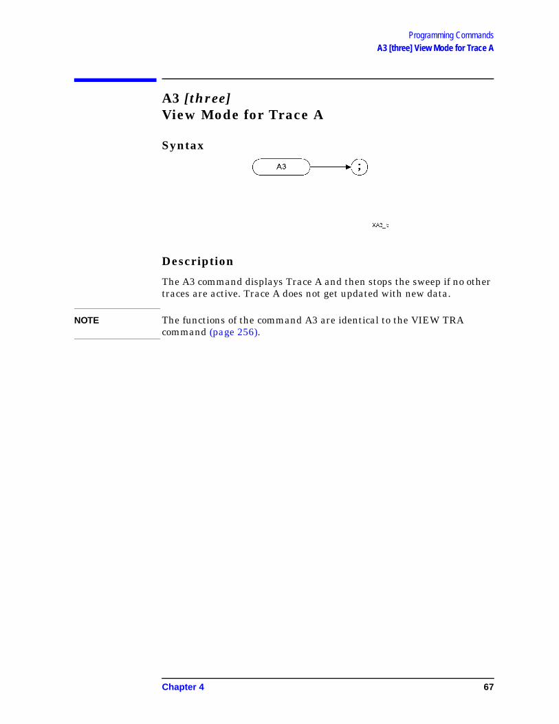
Programming CommandsA3 [three] View Mode for Trace A
A3 [three]View Mode for Trace A
Syntax
Description
The A3 command displays Trace A and then stops the sweep if no other traces are active. Trace A does not get updated with new data.
NOTE The functions of the command A3 are identical to the VIEW TRA command (page 256).
Chapter 4 67

Programming CommandsA4 [four] Blank Trace A
A4 [four]Blank Trace A
Syntax
Description
The A4 command blanks Trace A and stops the sweep if no other traces are active. Trace A is not updated.
NOTE The functions of the command A4 are identical to the BLANK TRA command (page 82).
68 Chapter 4

Programming CommandsAMB A minus B into A
AMBA minus B into A
Syntax
Description
The AMB command subtracts the points in Trace B from the corresponding points in Trace A, and sends the results to Trace A. Thus, AMB can restore the original trace after an APB or a KSc command has been executed.
NOTE On HP 8566B and HP 8568B analyzers, the AMB command operates continuously. That is, it continuously updates Trace A to display the results of Trace A minus Trace B until AMB is switched off.
This is not the case with HP 8566B/68B Code Compatibility. The AMB command is performed once only, using the trace data available at the time of execution.
NOTE The functions of the command AMB are identical to the C2 [two] command (page 87).
Chapter 4 69

Programming CommandsAMBPL (A minus B) plus Display Line into A
AMBPL(A minus B) plus Display Line into A
Syntax
Description
The AMBPL command does a point-by-point subtraction of Trace B from Trace A, and then adds the display line point values to the difference. The results are sent to Trace A
70 Chapter 4
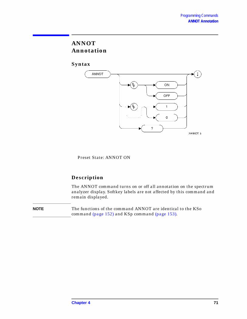
Programming CommandsANNOT Annotation
ANNOTAnnotation
Syntax
Preset State: ANNOT ON
Description
The ANNOT command turns on or off all annotation on the spectrum analyzer display. Softkey labels are not affected by this command and remain displayed.
NOTE The functions of the command ANNOT are identical to the KSo command (page 152) and KSp command (page 153).
Chapter 4 71

Programming CommandsAPB A Plus B to A
APBA Plus B to A
Syntax
Description
The APB command does a point-by-point addition of Trace A and Trace B, and sends the results to Trace A. Thus, APB can restore the original trace after an AMB or a C2 command has been executed.
NOTE The functions of the command APB are identical to the KSc command (page 131)
72 Chapter 4

Programming CommandsAT Attenuation
ATAttenuation
Syntax
Preset State: 10 dB
Step Increment: 10 dB
Description
Specifies the RF input attenuation.
Although any attenuation level from 0 dB to 70 dB in PSA series analyzers (0 dB to 65 dB in ESA-E series analyzers) can be specified using absolute values, you can never set attenuation below 10 dB using the DOWN steps. This is a safety feature to prevent inadvertent setting of attenuation to a level that could damage the analyzer.
CAUTION Signal levels above +30 dBm will damage the spectrum analyzer.
Table 4-2
Item Description/Default Range
Number Any real number or integer. Default units are dB.
PSA - 0 to70 dB specified absolutelyand
10 to 70 dB in 10 dB steps
ESA - 0 to 65 dB specified absolutelyand
10 to 65 dB in 10 dB steps
Chapter 4 73

Programming CommandsAT Attenuation
NOTE The OA option only returns the current value to the controller. It does not set the active function.
NOTE ESA series analyzers have a range of 10 dB to 65 dB when accessed in 10 dB steps. Stepping up from the default value of 10 dB, the sequence rises in 10 dB steps until an attenuation of 60 dB is reached. The next step will only be 5 dB as the analyzer’s upper limit is 65 dB will have been reached.
Stepping down from 65 dB reverses this sequence. The first step down from 65 dB is to 60 dB. Thereafter, each step is of 10 dB until an attenuation level of 10 dB is reached.
You cannot step down below 10 dB. To set levels below 10 dB, you must specify the attenuation absolutely. For example, to set attenuation to 5 dB, you must use the command AT 5DB.
74 Chapter 4
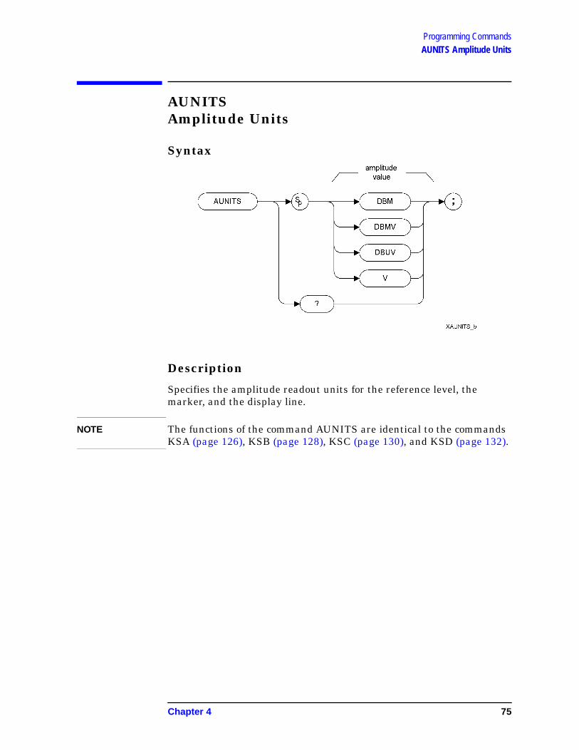
Programming CommandsAUNITS Amplitude Units
AUNITSAmplitude Units
Syntax
Description
Specifies the amplitude readout units for the reference level, the marker, and the display line.
NOTE The functions of the command AUNITS are identical to the commands KSA (page 126), KSB (page 128), KSC (page 130), and KSD (page 132).
Chapter 4 75

Programming CommandsAXB Exchange Trace A and Trace B
AXBExchange Trace A and Trace B
Syntax
Description
This command exchanges Trace A and Trace B, point by point.
NOTE The functions of the command AXB are identical to the EX command (page 109) and to the XCH TRA,TRB command (page 257).
76 Chapter 4

Programming CommandsB1 [one] Clear Write for Trace B
B1 [one]Clear Write for Trace B
Syntax
Description
The B1 command sets Trace B to clear write. That is, it continuously displays any signal present at the spectrum analyzer input. The B1 command initially clears Trace B, setting all elements to zero. The sweep trigger then signals the start of the sweep, and Trace B is continually updated as the sweep progresses. Subsequent sweeps send new amplitude information to the display addresses.
NOTE The functions of the command B1 are identical to the CLRW TRB command (page 92).
Chapter 4 77

Programming CommandsB2 [two] Maximum Hold for Trace B
B2 [two]Maximum Hold for Trace B
Syntax
Description
The B2 command updates each trace element with the maximum level detected while the trace is active.
NOTE The functions of the command B2 are identical to the MXMH TRB command (page 202).
78 Chapter 4

Programming CommandsB3 [three] View Mode for Trace B
B3 [three]View Mode for Trace B
Syntax
Description
The B3 command displays Trace B and then stops the sweep if no other traces are active. Trace B does not get updated.
NOTE The functions of the command B3 are identical to the VIEW TRB command (page 256).
Chapter 4 79

Programming CommandsB4 [four] Blank Trace B
B4 [four]Blank Trace B
Syntax
Description
The B4 command blanks Trace B and stops the sweep if no other traces are active. Trace B is not updated.
NOTE The functions of the command B4 are identical to the BLANK TRB command (page 82).
80 Chapter 4
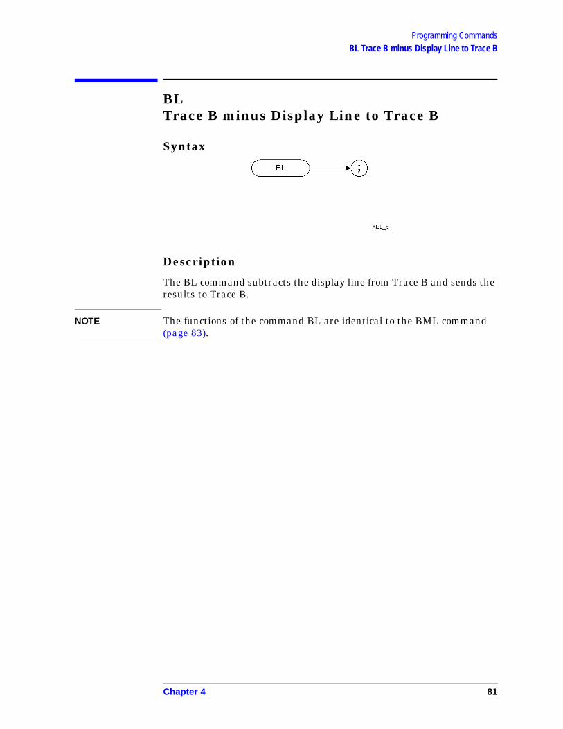
Programming CommandsBL Trace B minus Display Line to Trace B
BLTrace B minus Display Line to Trace B
Syntax
Description
The BL command subtracts the display line from Trace B and sends the results to Trace B.
NOTE The functions of the command BL are identical to the BML command (page 83).
Chapter 4 81

Programming CommandsBLANK Blank Trace
BLANKBlank Trace
Syntax
Preset State: BLANK TRB, BLANK TRC
Description
Blanks Trace 1, trace 2, or trace 3, and stops taking new data into the specified trace. TRA corresponds to Trace 1, TRB corresponds to Trace 2, and TRC corresponds to Trace 3.
NOTE The functions of the command BLANK are identical to the A4 command (page 68), the B4 command (page 80), and KSk command (page 143).
82 Chapter 4

Programming CommandsBML Trace B Minus Display Line
BMLTrace B Minus Display Line
Syntax
Description
The BML command subtracts the display line from trace B (point by point), and sends the difference to trace B. Trace B corresponds to Trace 2.
NOTE The functions of the command BML are identical to the BL command (page 81).
Chapter 4 83

Programming CommandsBTC Transfer Trace B to Trace C
BTCTransfer Trace B to Trace C
Syntax
Description
The BTC command transfers Trace B data to Trace C
NOTE Trace C cannot be an active trace. This means that the data in Trace C cannot be updated as the analyzer sweeps. To ensure that the current settings of the analyzer are reflected in the data transferred from Trace B to Trace C, you must follow the four step process below.
• Select single sweep mode (S2 or SNGLS command)
• Select the desired analyzer settings
• Take one complete sweep
• Transfer the data
NOTE The functions of the command BTC are identical to the KSl command (page 145). The BTC command also shares some functionality with the XCH TRB, TRC command (page 257).
84 Chapter 4

Programming CommandsBXC Exchange Trace B and Trace C
BXCExchange Trace B and Trace C
Syntax
Description
The BXC command exchanges Trace B data with Trace C data.
NOTE Trace C cannot be an active trace. This means that the data in Trace C cannot be updated as the analyzer sweeps. To ensure that the current settings of the analyzer are reflected in the data exchanged between Trace B and Trace C, you must follow the four step process below.
• Select single sweep mode (S2 or SNGLS command)
• Select the desired analyzer settings
• Take one complete sweep
• Exchange the data
NOTE The functions of the command BXC are identical to the KSi command (page 140) and to the XCH TRB,TRC command (page 257).
Chapter 4 85

Programming CommandsC1 [one] Set A Minus B Mode Off
C1 [one]Set A Minus B Mode Off
Syntax
Description
The C1 command turns the A Minus B mode off. That is, it switches off the functionality that was switched on by the C2 command (page 87) or by the AMB ON command (page 69).
NOTE The functions of the command C1 are identical to the AMB OFF command (page 69).
86 Chapter 4

Programming CommandsC2 [two] A Minus B Into A
C2 [two]A Minus B Into A
Syntax
Description
The C2 command subtracts the points in Trace B from the corresponding points in Trace A, and sends the results to Trace A. Thus, if your input signal remains unchanged, C2 can restore the original trace after an APB command (page 72) or a KSc (page 131) command has been executed.
NOTE The functions of the command C2 are identical to the AMB ON command (page 69).
NOTE On HP 8566B and HP 8568B analyzers, the C2 command operates continuously. That is, it continuously updates Trace A to display the results of Trace A minus Trace B until C2 is switched off by issuing the C1 command.
This is not the case with HP 8566B/68B Code Compatibility. The C2 command is performed once only, using the trace data available at the time of execution.
Chapter 4 87

Programming CommandsCA Couple Attenuation
CACouple Attenuation
Syntax
Description
During normal operation, the spectrum analyzer’s input attenuation is coupled to the reference level. This coupling keeps the mixer input at a level such that a continuous wave signal displayed at the reference level is at or below -10 dBm (or the value specified in the ML command or the ‘KS,’ command.)
The CA command sets the threshold to -10 dBm (or to the value specified by the ML command (page 198) or the KS, command (page 124)). The counterpart to the CA command is the AT command (page 73), which allows levels less than the threshold value at the mixer input.
88 Chapter 4

Programming CommandsCF Center Frequency
CFCenter Frequency
Syntax
Description
The CF command specifies the value of the center frequency.
The step size depends on whether the frequency has been coupled to the span width using the CS command (page 95). When coupled, the step size is 10% of the span, or one major graticule division; when uncoupled, the step size is determined by the SS command (page 234).
NOTE The OA option only returns the current value to the controller. It does not set the active function.
NOTE Although the spectrum analyzer allows entry of frequencies not in the
Table 4-3
Item Description/Default Range
REAL Any real or integer number. Default unit is HZ.
Frequency range of the spectrum analyzer
Chapter 4 89
Programming CommandsCF Center Frequency
specified frequency range, using frequencies outside the frequency span of the spectrum analyzer is not recommended and is not warranted to meet specifications.
90 Chapter 4

Programming CommandsCLRAVG Clear Average
CLRAVGClear Average
Syntax
Description
The CLRAVG command restarts the VAVG command by resetting the number of averaged sweeps to one. The video averaging routine resets the number of sweeps, but does not stop video averaging. Use “VAVG OFF;” to stop video averaging.
Chapter 4 91

Programming CommandsCLRW Clear Write
CLRWClear Write Clears the specified trace and enables trace data acquisition.
Syntax
Preset State: CLRW TRA
Description
The CLRW command places the indicated trace in clear-write mode. Data acquisition begins at the next sweep. (See the TS command (page 251) for more information about data acquisition.)
TRA corresponds to Trace 1 and TRB corresponds to Trace 2.
NOTE The functions of the command CLRW are identical to the A1 command (page 65) and B1 command (page 77).
92 Chapter 4

Programming CommandsCONTS Continuous Sweep
CONTSContinuous Sweep
Syntax
Preset State: CONTS
Description
The CONTS command sets the spectrum analyzer to continuous sweep mode. In the continuous sweep mode, the spectrum analyzer takes its next sweep as soon as possible after the current sweep (as long as the trigger conditions are met). A sweep may temporarily be interrupted by data entries made over the remote interface or from the front panel.
NOTE The functions of the command CONTS are identical to the S1 command (page 226).
Chapter 4 93

Programming CommandsCR Couple Resolution Bandwidth
CRCouple Resolution Bandwidth
Syntax
Description
The CR command couples the resolution bandwidth to the video bandwidth and to the sweep time.
The counterpart to the CR command is the RB command (page 217) which breaks the coupling. Use the CR command to re-establish coupling after executing an RB command.
NOTE CR uses the coupling settings from the ESA-E or the PSA analyzer. These may differ from the HP 8566B and HP 8568B settings.
94 Chapter 4

Programming CommandsCS Couple Frequency Step Size
CSCouple Frequency Step Size
Syntax
Description
The CS command couples the center frequency step size to the span width so that the step size equals 10% of the span width, or one major graticule division.
The counterpart to the CS command is the SS command (page 234) which breaks the coupling. Use the CS command to re-establish coupling after an SS command has been executed.
Chapter 4 95
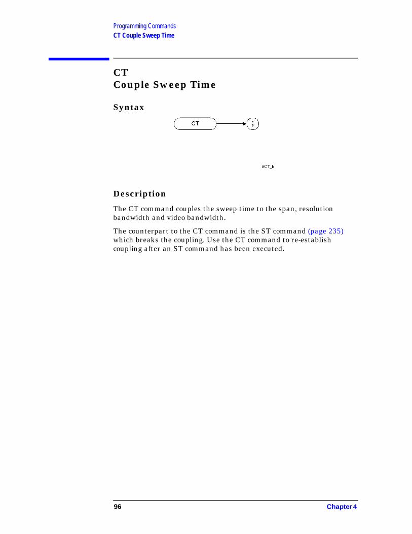
Programming CommandsCT Couple Sweep Time
CTCouple Sweep Time
Syntax
Description
The CT command couples the sweep time to the span, resolution bandwidth and video bandwidth.
The counterpart to the CT command is the ST command (page 235) which breaks the coupling. Use the CT command to re-establish coupling after an ST command has been executed.
96 Chapter 4

Programming CommandsCV Couple Video Bandwidth
CVCouple Video Bandwidth
Syntax
Description
The CV command couples the video bandwidth to the resolution bandwidth.
The counterpart to the CV command is the VB command (page 254) which breaks the coupling. Use the CV command to re-establish coupling after executing a VB command.
NOTE CV uses the coupling settings from the ESA-E or the PSA analyzer. These may differ from the HP 8566B and HP 8568B settings.
Chapter 4 97

Programming CommandsDA Display Address
DADisplay Address
Syntax
Description
The DA command returns the contents of the specified memory address.
.
NOTE The DA command only supports the use of DA 1 (equivalent to the commands TA (page 242) and TRA? (page 247), DA 1025 (equivalent to the commands TB (page 243) and TRB? (page 248), and DA 3073 (equivalent to the TRC? command.) The TRC? command is not supported on Option 266.
98 Chapter 4

Programming CommandsDET Detection Mode
DETDetection Mode
Syntax
Preset State: DET POS
Description
The DET command selects the type of spectrum analyzer detection (positive-peak, negative peak, sample or normal).
POS enables positive-peak detection, which displays the maximum video signal detected over a number of instantaneous samples for a particular frequency.
SMP enables sample detection, which uses the instantaneous video signal value. Video averaging and noise-level markers, when activated, activate sample detection automatically.
NEG enables negative peak detection in sweep times of less than or equal to 200 ms.
NRM (PSA) PSA series analyzers only - enables the ‘rosenfell’ detection algorithm that selectively chooses between positive and negative values.
NRM (ESA) ESA series analyzers only - normal detection is not possible on ESA series analyzers, so the detection will default to positive-peak detection (POS) when NRM is selected.
Chapter 4 99

Programming CommandsDET Detection Mode
NOTE The functions of the DET command are identical to the KSa command (page 127), the KSb command, (page 129) the KSd command (page 133) and KSe command (page 135).
100 Chapter 4

Programming CommandsDL Display Line
DLDisplay Line
Syntax
Preset State: DL OFF
Step Increment: 1 major graticule division
Description
Defines the level of the display line and displays it on the spectrum analyzer’s screen.
NOTE The OA option only returns the current value to the controller. It does not set the active function.
Table 4-4
Item Description/Default Range
REAL Any real or integer number. Default units are dBm.
Dependent on the reference level
Chapter 4 101

Programming CommandsDLE Display Line Enable
DLEDisplay Line Enable
Syntax
Description
The DLE command enables or disables the display line.
102 Chapter 4

Programming CommandsDONE Done
DONEDone
Syntax
Description
Allows you to determine when the spectrum analyzer has parsed a list of spectrum analyzer commands and has executed all commands prior to and including DONE. The DONE command returns a value of “1” when all commands in a command string or command list have been completed.
If a take sweep (TS command (page 251)) precedes the command list, the TS command acts as a synchronizing function since the command list execution begins after the sweep has been completed.
Chapter 4 103

Programming CommandsE1[one] Peak Marker
E1[one]Peak Marker
Syntax
Description
The E1 command positions the marker at the signal peak.
NOTE The functions of the E1 command are identical to MKPK (no secondary keyword) and MKPK HI (page 188).
104 Chapter 4

Programming CommandsE2 [two] Marker to Center Frequency
E2 [two]Marker to Center Frequency
Syntax
Description
The E2 command positions the marker on the screen at the center frequency position.
NOTE The functions of the E2 command are identical to the MKCF command (page 176).
Chapter 4 105

Programming CommandsE3 [three] Delta Marker Step Size
E3 [three]Delta Marker Step Size
Syntax
Description
The E3 command establishes the center frequency step size as being the frequency difference between the delta marker and the active marker.
NOTE The functions of the E3 command are identical to the MKSS command (page 195).
106 Chapter 4

Programming CommandsE4 [four] Marker to Reference Level
E4 [four]Marker to Reference Level
Syntax
Description
The E4 command moves the active marker to the reference level.
NOTE The functions of the E4 command are identical to the MKRL command (page 193).
Chapter 4 107

Programming CommandsERR List Error Codes
ERRList Error Codes
Syntax
Description
This command returns an integer list of all error codes.
108 Chapter 4

Programming CommandsEX Exchange Trace A and Trace B
EXExchange Trace A and Trace B
Syntax
Description
This command exchanges Trace A and Trace B, point by point.
NOTE The functions of the EX command are identical to the AXB command (page 76) and to the XCH TRA,TRBcommand (page 257).
Chapter 4 109

Programming CommandsFA Start Frequency
FAStart Frequency
Syntax
Step Increment: Frequency span divided by 10
Description
The FA command specifies the start frequency value. The start frequency is equal to the center frequency minus (the span divided by two) (FA = CF − SP/2). Changing the start frequency changes the center frequency and span.
NOTE The OA option only returns the current value to the controller. It does not set the active function to the start frequency.
Table 4-5
Item Description/Default Range
REAL Any real or integer number. Default unit is Hz.
Frequency range of the spectrum analyzer
110 Chapter 4
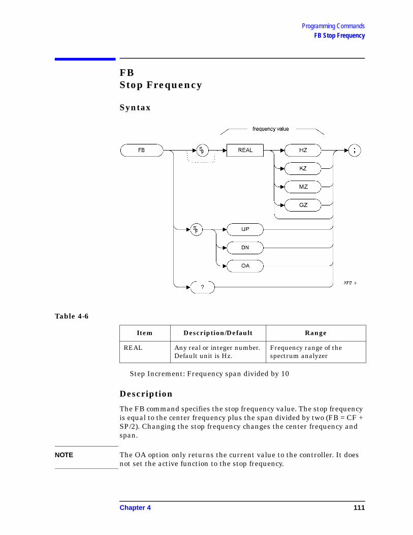
Programming CommandsFB Stop Frequency
FBStop Frequency
Syntax
Step Increment: Frequency span divided by 10
Description
The FB command specifies the stop frequency value. The stop frequency is equal to the center frequency plus the span divided by two (FB = CF + SP/2). Changing the stop frequency changes the center frequency and span.
NOTE The OA option only returns the current value to the controller. It does not set the active function to the stop frequency.
Table 4-6
Item Description/Default Range
REAL Any real or integer number. Default unit is Hz.
Frequency range of the spectrum analyzer
Chapter 4 111

Programming CommandsFOFFSET Frequency Offset
FOFFSETFrequency Offset
Syntax
Preset State: 0 Hz
Description
Specifies the frequency offset for all absolute frequency readouts such as center frequency.
The FOFFSET command selects a value that offsets the frequency scale for all absolute frequency readouts (for example, center frequency). Relative values such as span and marker delta are not offset.
When an offset is in effect, it is displayed beneath the bottom graticule line on the spectrum analyzer screen.
Table 4-7
Item Description/Default Range
REAL Any real or integer number. Default unit is Hz.
112 Chapter 4

Programming CommandsFOFFSET Frequency Offset
Execute “FOFFSET 0;” or “IP;” to turn off the offset.
NOTE The OA option only returns the current value to the controller. It does not set the active function.
NOTE The functions of the FOFFSET command are identical to the KSV command (page 155).
Chapter 4 113

Programming CommandsFPKA Fast Preselector Peak
FPKAFast Preselector Peak
Syntax
Description
The FPKA command automatically adjusts the preselector frequency to yield the greatest signal level at the active marker. It returns the amplitude of the active marker.
NOTE The FPKA command is only available when the analyzer’s upper frequency limit is greater than 3 GHz. The command is not supported in analyzers with an upper frequency limit of 3 GHz or less, and will return an error message when used.
NOTE The FPKA command is not a valid HP8568B command, and is therefore not supported when the remote language is HP8568B.
114 Chapter 4

Programming CommandsFS Full Span
FSFull Span
Syntax
Description
The FS command sets the frequency span of the spectrum analyzer to full span. Resolution bandwidth, video bandwidth, and sweep time are all set to auto-coupled.
NOTE The functions of the FS command are identical to the LF command (page 160).
NOTE Whenever the frequency range of the analyzer you are using does not match the remote language’s own range (2 to 22 GHz for HP 8566B and 0.0 to 1.5 GHz for HP 8568B), the span will be limited by the capabilities of the analyzer. The table below lists the frequency ranges of Agilent’s ESA-E series and PSA series analyzers.
Chapter 4 115

Programming CommandsFS Full Span
Table 4-8 Frequency ranges of the Agilent ESA and PSA spectrum analyzers
Spectrum Analyzer Model Start Frequency
Stop Frequency
E4401B 9 kHz 1.5 GHz
E4402B 9 kHza 3.0 GHz
E4404B 9 kHza 6.7 GHz
E4405B 9 kHza 13.2 GHz
E4407B 9 kHza 26.5 GHz
E4440A 3 Hz 26.5 GHz
E4443A 3 Hz 6.7 GHz
E4445A 3 Hz 13.2 GHz
E4446A 3 Hz 44.0 GHz
E4448A 3 Hz 50.0 GHz
a. 100 Hz with Option UKB, the Low Frequency Extension
116 Chapter 4

Programming CommandsGRAT Graticule
GRATGraticule
Syntax
Preset State: GRAT ON
Description
Turns the graticule on or off.
NOTE The functions of the GRAT command are identical to the KSm command (page 148) and the KSn command (page 150).
Chapter 4 117

Programming CommandsI1 [one] Set RF Coupling to DC
I1 [one]Set RF Coupling to DC
Syntax
Description
The I1 [one] command sets the RF coupling to DC if your analyzer is capable of being switched. If your analyzer cannot be switched to DC coupling, the command will have no effect but an error message will not be generated.
Whether or not your analyzer can be AC coupled, DC coupled, or both depends on both the analyzer’s model number, and on whether or not Option UKB (Low Frequency Extension) has been installed. The tables below list the frequency specifications for all ESA-E series and PSA analyzers for both DC and AC coupling.
NOTE The I1 [one] command is not supported when the remote language is HP8566B.
Table 4-9 HP 8568A/B Analyzer Frequency Coupling Specifications
DC Coupled Range AC Coupled Range
Analyzer Model
Min. Freq.
Max. Freq.
Min. Freq.
Max. Freq.
HP 8568A/B 100 Hz 1.5 GHz 100 kHz 1.5 GHz
118 Chapter 4
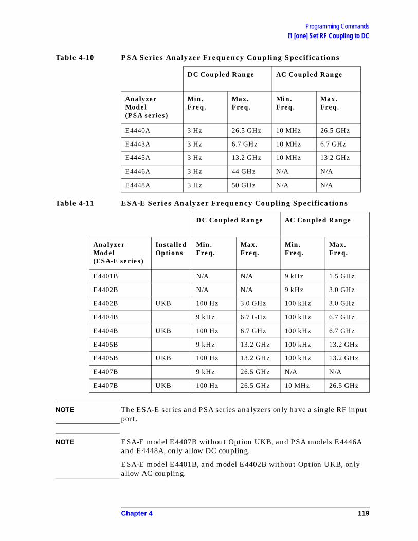
Programming CommandsI1 [one] Set RF Coupling to DC
NOTE The ESA-E series and PSA series analyzers only have a single RF input port.
NOTE ESA-E model E4407B without Option UKB, and PSA models E4446A and E4448A, only allow DC coupling.
ESA-E model E4401B, and model E4402B without Option UKB, only allow AC coupling.
Table 4-10 PSA Series Analyzer Frequency Coupling Specifications
DC Coupled Range AC Coupled Range
Analyzer Model (PSA series)
Min. Freq.
Max. Freq.
Min. Freq.
Max. Freq.
E4440A 3 Hz 26.5 GHz 10 MHz 26.5 GHz
E4443A 3 Hz 6.7 GHz 10 MHz 6.7 GHz
E4445A 3 Hz 13.2 GHz 10 MHz 13.2 GHz
E4446A 3 Hz 44 GHz N/A N/A
E4448A 3 Hz 50 GHz N/A N/A
Table 4-11 ESA-E Series Analyzer Frequency Coupling Specifications
DC Coupled Range AC Coupled Range
Analyzer Model(ESA-E series)
Installed Options
Min. Freq.
Max. Freq.
Min. Freq.
Max. Freq.
E4401B N/A N/A 9 kHz 1.5 GHz
E4402B N/A N/A 9 kHz 3.0 GHz
E4402B UKB 100 Hz 3.0 GHz 100 kHz 3.0 GHz
E4404B 9 kHz 6.7 GHz 100 kHz 6.7 GHz
E4404B UKB 100 Hz 6.7 GHz 100 kHz 6.7 GHz
E4405B 9 kHz 13.2 GHz 100 kHz 13.2 GHz
E4405B UKB 100 Hz 13.2 GHz 100 kHz 13.2 GHz
E4407B 9 kHz 26.5 GHz N/A N/A
E4407B UKB 100 Hz 26.5 GHz 10 MHz 26.5 GHz
Chapter 4 119

Programming CommandsI2 [two] Set RF Coupling to AC
I2 [two]Set RF Coupling to AC
Syntax
Description
The I2 [two] command sets the RF coupling to AC if your analyzer is capable of being switched. If your analyzer cannot be switched to AC coupling, the command will have no effect but an error message will not be generated.
Whether or not your analyzer can be AC coupled, DC coupled, or both depends on both the analyzer’s model number, and on whether or not Option UKB (Low Frequency Extension) has been installed. The tables below list the frequency specifications for all ESA-E series and PSA analyzers for both DC and AC coupling.
NOTE The I2 [two] command is not supported when the remote language is HP8566B.
Table 4-12 HP 8568A/B Analyzer Frequency Coupling Specifications
DC Coupled Range AC Coupled Range
Analyzer Model
Min. Freq.
Max. Freq.
Min. Freq.
Max. Freq.
HP 8568A/B 100 Hz 1.5 GHz 100 kHz 1.5 GHz
120 Chapter 4

Programming CommandsI2 [two] Set RF Coupling to AC
NOTE The ESA-E series and PSA series analyzers only have a single RF input port.
NOTE ESA-E model E4407B without Option UKB, and PSA models E4446A and E4448A, only allow DC coupling.
ESA-E model E4401B, and model E4402B without Option UKB, only allow AC coupling.
Table 4-13 PSA Series Analyzer Frequency Coupling Specifications
DC Coupled Range AC Coupled Range
Analyzer Model (PSA series)
Min. Freq.
Max. Freq.
Min. Freq.
Max. Freq.
E4440A 3 Hz 26.5 GHz 10 MHz 26.5 GHz
E4443A 3 Hz 6.7 GHz 10 MHz 6.7 GHz
E4445A 3 Hz 13.2 GHz 10 MHz 13.2 GHz
E4446A 3 Hz 44 GHz N/A N/A
E4448A 3 Hz 50 GHz N/A N/A
Table 4-14 ESA-E Series Analyzer Frequency Coupling Specifications
DC Coupled Range AC Coupled Range
Analyzer Model(ESA-E series)
Installed Options
Min. Freq.
Max. Freq.
Min. Freq.
Max. Freq.
E4401B N/A N/A 9 kHz 1.5 GHz
E4402B N/A N/A 9 kHz 3.0 GHz
E4402B UKB 100 Hz 3.0 GHz 100 kHz 3.0 GHz
E4404B 9 kHz 6.7 GHz 100 kHz 6.7 GHz
E4404B UKB 100 Hz 6.7 GHz 100 kHz 6.7 GHz
E4405B 9 kHz 13.2 GHz 100 kHz 13.2 GHz
E4405B UKB 100 Hz 13.2 GHz 100 kHz 13.2 GHz
E4407B 9 kHz 26.5 GHz N/A N/A
E4407B UKB 100 Hz 26.5 GHz 10 MHz 26.5 GHz
Chapter 4 121

Programming CommandsID Identify
IDIdentify
Syntax
Description
The ID command returns the current remote language to the controller (for example, “HP8566B”).
NOTE The response value is determined by your remote language selection. This is configured via the front-panel menu selection for remote ID. See “Configuring Option 266 - ESA and PSA Analyzers” on page 12 for details.
122 Chapter 4

Programming CommandsIP Instrument Preset
IPInstrument Preset
Syntax
Description
Performs an instrument preset, setting the analyzer back to its factory settings.
Instrument preset automatically occurs when you turn on the spectrum analyzer. IP is a good starting point for many measurement processes. When IP is executed remotely, the spectrum analyzer does not necessarily execute a complete sweep, however. You should execute a take sweep (TS) to ensure that the trace data is valid after an IP.
NOTE The functions of the IP command are identical to the KST command (page 154).
NOTE If the external amplifier gain has been set, executing an IP command will not reset this value. This is to protect the analyzer.
Chapter 4 123
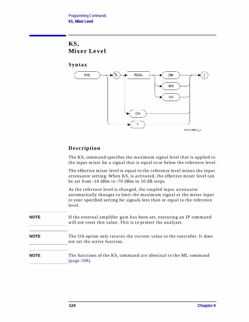
Programming CommandsKS, Mixer Level
KS,Mixer Level
Syntax
Description
The KS, command specifies the maximum signal level that is applied to the input mixer for a signal that is equal to or below the reference level.
The effective mixer level is equal to the reference level minus the input attenuator setting. When KS, is activated, the effective mixer level can be set from -10 dBm to -70 dBm in 10 dB steps.
As the reference level is changed, the coupled input attenuator automatically changes to limit the maximum signal at the mixer input to your specified setting for signals less than or equal to the reference level.
NOTE If the external amplifier gain has been set, executing an IP command will not reset this value. This is to protect the analyzer.
NOTE The OA option only returns the current value to the controller. It does not set the active function.
NOTE The functions of the KS, command are identical to the ML command (page 198).
124 Chapter 4

Programming CommandsKS= Marker Counter Resolution
KS=Marker Counter Resolution
Syntax
NOTE The marker counter can be specified in time units when operating in the time domain.
Description
Specifies the resolution of the marker frequency counter.
NOTE This command is not supported when the remote language is HP8566B.
NOTE The functions of the KS= command are identical to the MKFCR command (page 181).
NOTE On PSA analyzers, setting the marker frequency resolution will cause the Gate Time to change. The Gate Time is calculated using the following formula:
For restrictions on the Gate Time, refer to the PSA User’s and Programmer’s Reference Guide.
Gate Time 1Resolution Value-----------------------------------------=
Chapter 4 125

Programming CommandsKSA Amplitude in dBm
KSAAmplitude in dBm
Syntax
Description
The KSA command sets the amplitude readout (reference level, marker, display line and threshold) to dBm units.
NOTE The functions of the KSA command are identical to the AUNITS DBM command (page 75).
126 Chapter 4

Programming CommandsKSa Normal Detection
KSaNormal Detection
Syntax
Description
The KSa command selects normal input detection. That is, it enables the ‘rosenfell’ detection algorithm that selectively chooses between positive and negative values.
NOTE Normal detection is only possible in PSA series analyzers. The KSa command will default to positive peak detection (KSb) (page 129) when executed on an ESA analyzer.
NOTE The functions of the KSa command are identical to the DET NRM command (page 99).
Chapter 4 127

Programming CommandsKSB Amplitude in dBmV
KSBAmplitude in dBmV
Syntax
Description
The KSB command sets the amplitude readout (reference level, marker, display line and threshold) to dBmV units.
NOTE The functions of the KSB command are identical to the AUNITS DBMV command (page 75).
128 Chapter 4

Programming CommandsKSb Positive Peak Detection
KSbPositive Peak Detection
Syntax
Description
The KSb command enables positive peak input detection for displaying trace information. Trace elements are only updated when the detected signal level is greater than the previous signal level.
NOTE The functions of the KSa command are identical to the DET POS command (page 99).
Chapter 4 129

Programming CommandsKSC Amplitude in dBuV
KSCAmplitude in dBuV
Syntax
Description
The KSC command sets the amplitude readout (reference level, marker, display line and threshold) to dBuV units.
NOTE The functions of the KSC command are identical to the AUNITS DBUV command (page 75).
130 Chapter 4

Programming CommandsKSc A Plus B to A
KScA Plus B to A
Syntax
Description
The KSc command does a point-by-point addition of Trace A and Trace B, and sends the results to Trace A. Thus, if your input signal remains unchanged, KSc can restore the original trace after an AMB or a C2 command has been executed.
NOTE The functions of the command KSc are identical to the APB command (page 72).
Chapter 4 131

Programming CommandsKSD Amplitude in Volts
KSDAmplitude in Volts
Syntax
Description
The KSD command sets the amplitude readout (reference level, marker, display line and threshold) to voltage units.
NOTE The functions of the KSD command are identical to the AUNITS V command (page 75).
132 Chapter 4

Programming CommandsKSd Negative Peak Detection
KSdNegative Peak Detection
Syntax
Description
The KSd command selects negative-peak input detection for displaying trace information. Each trace element is updated with the minimum value detected during the sweep.
NOTE The functions of the command KSd are identical to the DET NEG command (page 99).
Chapter 4 133

Programming CommandsKSE Title Mode
KSETitle Mode
Syntax
Description
The KSE command activates the title mode, writing a message to the top line of the display.
NOTE The characters that Option 266 will accept as a terminator include the ‘at’ sign (@), the Line Feed character (\n), and end of input. The Carriage Return (\r) character cannot be specified as a terminator, although it is accepted when Carriage Return marks the end of your input.
134 Chapter 4

Programming CommandsKSe Sample Detection
KSeSample Detection
Syntax
Description
The KSe command selects sample input detection for displaying trace information.
NOTE The functions of the command KSe are identical to the DET SMP command (page 99).
Chapter 4 135

Programming CommandsKSG Video Averaging On
KSGVideo Averaging On
Syntax
Description
The KSG command enables video averaging. During video averaging, two traces are displayed simultaneously. Trace C shows the signal as seen at the input detector, while Trace A or Trace B show the same signal after averaging.
Before executing the KSG command, select Trace A or Trace B as the active trace (CLRW command (page 92)) and blank the remaining trace.
NOTE The OA option only returns the current value to the controller. It does not set the active function.
NOTE The functions of the KSG command are identical to the VAVG ON command (page 252).
136 Chapter 4

Programming CommandsKSg Display Off
KSgDisplay Off
Syntax
Description
The KSg command turns the analyzer’s display Off.
On the original HP 8566B and HP 8568B spectrum analyzers, this command turned the CRT beam power off to avoid unnecessary wear on the CRT. Although this command is supported, displays used on the ESA-E and PSA analyzers are not subject to wear.
Chapter 4 137

Programming CommandsKSH Video Averaging Off
KSHVideo Averaging Off
Syntax
Description
The KSH command switches video averaging off.
Before executing the KSH command, select Trace A or Trace B as the active trace (CLRW command (page 92)) and blank the remaining trace.
NOTE The functions of the KSH command are identical to the VAVG OFF command (page 252).
138 Chapter 4
Programming CommandsKSh Display On
KShDisplay On
Syntax
Description
The KSh command turns the analyzer’s display On.
On the original HP 8566B and HP 8568B spectrum analyzers, CRT beam power was often switched Off to prevent wear of the CRT. This command (KSh) was used to turn the CRT beam power on again. Although this command is supported, displays used on the ESA-E and PSA analyzers are not subject to wear.
Chapter 4 139

Programming CommandsKSi Exchange Trace B and Trace C
KSiExchange Trace B and Trace C
Syntax
Description
The KSi command exchanges Trace B data with Trace C data.
NOTE Trace C cannot be an active trace. This means that the data in Trace C cannot be updated as the analyzer sweeps. To ensure that the current settings of the analyzer are reflected in the data exchanged between Trace B and Trace C, you must follow the four step process below.
• Select single sweep mode (S2 (page 227) or SNGLS command (page 230))
• Select the desired analyzer settings
• Take one complete sweep using the TS command (page 251)
• Exchange the data
NOTE The functions of the command KSi are identical to the BXC command (page 85) and the XCH TRB,TRC command (page 257).
140 Chapter 4
Programming CommandsKSj View Trace C
KSjView Trace C
Syntax
Description
The KSj command displays Trace C.
NOTE The functions of the command KSj are identical to the VIEW TRC command (page 256).
Chapter 4 141

Programming CommandsKSK Marker to Next Peak
KSKMarker to Next Peak
Syntax
Description
If there is a marker on the screen, the KSK command moves this marker to the next signal peak of lower amplitude.
NOTE The functions of the KSK command are similar to the MKPK NH command (page 188), except that KSK does not take into account either the marker peak excursion value or the threshold value. For more details on marker peak excursion, see the MKPX command (page 190). For more information on threshold, see the TH command (page 245).
NOTE This command is not supported when the remote language is HP8568B.
142 Chapter 4

Programming CommandsKSk Blank Trace C
KSkBlank Trace C
Syntax
Description
The KSj command blanks Trace C.
NOTE The functions of the command KSk are identical to the BLANK TRC command (page 82))
Chapter 4 143

Programming CommandsKSL Marker Noise Off
KSLMarker Noise Off
Syntax
Description
The KSL command disables the noise density function which displays the RMS noise density at the marker. KSL does not blank the marker.
NOTE The functions of the KSL command are identical to the MKNOISE OFF command (page 184).
144 Chapter 4
Programming CommandsKSl Transfer Trace B to Trace C
KSlTransfer Trace B to Trace C
Syntax
Description
The KSl command transfers Trace B data to Trace C
NOTE Trace C cannot be an active trace. This means that the data in Trace C cannot be updated as the analyzer sweeps. To ensure that the current settings of the analyzer are reflected in the data transferred from Trace B to Trace C, you must follow the four step process below.
• Select single sweep mode (S2 (page 227) or SNGLS command (page 230))
• Select the desired analyzer settings
• Take one complete sweep using the TS command (page 251)
• Transfer the data
NOTE The functions of the command KSl are identical to the BTC command (page 84).
Chapter 4 145

Programming CommandsKSM Marker Noise On
KSMMarker Noise On
Syntax
Description
The KSM command displays the noise density at the marker. The noise density is normalized to a 1Hz bandwidth.
NOTE The functions of the KSM command are identical to the MKNOISE ON command (page 184).
NOTE The OA option only returns the current value to the controller. It does not set the active function.
NOTE If an MKD command or an M3 command is executed with the marker noise function active, the marker amplitude displayed and returned by the MKA? command (page 174) or the MA command (page 167) is the difference between the noise densities at the reference marker and at the delta marker.
If an MKD command or an M3 command is executed before marker noise has been activated, the marker noise amplitude that is displayed on the screen is the difference between the carrier wave power and the noise density at the delta marker position.
However, the value returned by an MKA? (page 174) command or by an MA command (page 167) will always be the difference between the noise densities at the two markers. That is, the values returned by MKA? and MA do not always agree with those displayed on the screen. These returned values will only remain correct as long as there has been no change made to either the delta marker or the marker noise from the front panel.
The nominal noise bandwidth to RBW ratio for the RBW filters used in the ESA-E series analyzers is 1.128 for RBWs of 1 kHz and higher, and 1.055 for RBWs of less than 1 kHz. The nominal ratio for PSA analyzers
146 Chapter 4

Programming CommandsKSM Marker Noise On
is 1.055 for all RBWs. The nominal ratio for the HP 8566 family of analyzers is 1.128 for RBWs 100 kHz and higher, and 1.114 for RBWs of 30 kHz and lower.
Chapter 4 147

Programming CommandsKSm Graticule Off
KSmGraticule Off
Syntax
Description
The KSm command blanks the graticule on the analyzer display.
NOTE The functions of the command KSm are identical to the GRAT OFF command (page 117).
148 Chapter 4

Programming CommandsKSN Marker Minimum
KSNMarker Minimum
Syntax
Description
The KSN command moves the marker to the minimum value detected.
NOTE The functions of the KSN command are identical to the MKMIN command (page 182).
NOTE This command is not supported when the remote language is HP8568B.
Chapter 4 149

Programming CommandsKSn Graticule On
KSnGraticule On
Syntax
Description
The KSn command turns on the graticule on the analyzer display.
NOTE The functions of the command KSn are identical to the GRAT ON command (page 117).
150 Chapter 4
Programming CommandsKSO Marker Span
KSOMarker Span
Syntax
Description
The KSO command operates only when the delta marker is On (see MKD (page 177) or M3 (page 165)). When the delta marker is on and the KSO command is executed, the left marker specifies the start frequency, and the right marker specifies the stop frequency. If the delta marker is off, the command does nothing.
NOTE If the active marker is not a delta marker, there is no change in its position.
NOTE The functions of the KSO command are identical to the MKSP command (page 194).
Chapter 4 151

Programming CommandsKSo Annotation Off
KSoAnnotation Off
Syntax
Description
The KSo command blanks the annotation on the analyzer display.
NOTE The functions of the command KSo are identical to the ANNOT OFF command (page 71).
152 Chapter 4

Programming CommandsKSp Annotation On
KSpAnnotation On
Syntax
Description
The KSp command activates the annotation on the analyzer display.
NOTE The functions of the command KSp are identical to the ANNOT ON command (page 71).
Chapter 4 153

Programming CommandsKST Fast Preset
KSTFast Preset
Syntax
Description
Performs an instrument preset, setting the analyzer back to its factory settings.
NOTE There is no fast preset for ESA and PSA series analyzers. Instead, HP8566B/68B Code Compatibility performs an instrument preset (IP) when the KST command is issued. The functions of the command KST are therefore identical to the IP command (page 123).
154 Chapter 4

Programming CommandsKSV Frequency Offset
KSVFrequency Offset
Syntax
Description
The KSV command allows you to specify a value that offsets the frequency scale for all absolute frequency readouts, for example, center frequency. Relative values, for example, span and delta marker, are not offset.
NOTE The OA option only returns the current value to the controller. It does not set the active function.
NOTE The functions of the KSV command are identical to the FOFFSET command (page 112).
Chapter 4 155

Programming CommandsKSx External Trigger
KSxExternal Trigger
Syntax
Description
The KSx command activates the normal external trigger mode. When the KSx command is executed, the RF input signal is only displayed when the external trigger level exceeds the trigger threshold level.
NOTE If an HP 8566B or an HP 8568B analyzer is in zero span and the sweep time is less than 20 msec, the display only gets refreshed when a fresh trace has been taken. This can cause the displayed trace to flicker. In Option 266, all traces are displayed continuously, so all traces are therefore free of flicker.
NOTE The functions of the command KSx are identical to the TM EXT command (page 246).
156 Chapter 4

Programming CommandsKSy Video Trigger
KSyVideo Trigger
Syntax
Description
The KSy command activates the normal video trigger mode. When the KSy command is executed, the RF input signal is only displayed when the video trigger signal, which is internally triggered off the input signal, exceeds the trigger threshold level.
NOTE If an HP 8566B or an HP 8568B analyzer is in zero span and the sweep time is less than 20 msec, the display only gets refreshed when a fresh trace has been taken. This can cause the displayed trace to flicker. In Option 266, all traces are displayed continuously, so all traces are therefore free of flicker.
NOTE The functions of the command KSy are identical to the TM VID command (page 246) and to the T4 command (page 241).
Chapter 4 157

Programming CommandsKSZ Reference Level Offset
KSZReference Level Offset
Syntax
Description
The KSZ command offsets all amplitude readouts on the display but without affecting the trace.
Once activated, the KSZ command displays the amplitude offset on the left side of the screen.
Entering KSZ 0 or presetting the spectrum analyzer eliminates an amplitude offset.
NOTE The OA option only returns the current value to the controller. It does not set the active function.
NOTE The functions of the KSZ command are identical to the ROFFSET command (page 224).
158 Chapter 4

Programming CommandsLO [zero] Display Line Off
LO [zero]Display Line Off
Syntax
Description
The L0 [zero] command disables the display line.
NOTE The functions of the L0 [zero] command are identical to the DLE OFF command (page 102).
Chapter 4 159

Programming CommandsLF Low Frequency Preset
LFLow Frequency Preset
Syntax
Description
Performs a low frequency preset. That is, it selects a Start Frequency of 0 Hz and a Stop Frequency of 2.5 GHz, a Reference Level of 0dBm, and sets all coupled functions to automatic.
NOTE This command is not supported when the remote language is HP8568B.
160 Chapter 4

Programming CommandsLG Logarithmic Scale
LGLogarithmic Scale
Syntax
Description
Specifies the amplitude (vertical graticule divisions) as logarithmic units, without changing the reference level.
NOTE The OA option only returns the current value to the controller. It does not set the active function.
Chapter 4 161

Programming CommandsLN Linear Scale
LNLinear Scale
Syntax
Description
Scales the amplitude (vertical graticule divisions) proportional to the input voltage, without changing the reference level. The bottom line of the graticule represents 0 volts.
162 Chapter 4

Programming CommandsM1 [one] Marker Off
M1 [one]Marker Off
Syntax
Description
The M1 [one] command blanks any markers showing on the display.
NOTE The functions of the M1 [one] command are identical to the MKOFF ALL command (page 186).
Chapter 4 163

Programming CommandsM2 [two] Marker Normal
M2 [two]Marker Normal
Syntax
Description
The M2 [two] command moves the active marker to the marker frequency. If the active marker has not been declared with MKACT, a normal marker is turned on and this active marker is assumed to be 1. If the active marker type is not currently normal (for example, it is delta or peak), the M2 command will change it to a normal marker.
NOTE The OA option only returns the current value to the controller. It does not set the active function.
NOTE The functions of the M2 command are identical to the MKN command (page 183).
164 Chapter 4

Programming CommandsM3 [three] Delta Marker
M3 [three]Delta Marker
Syntax
Description
The M3 [three] command computes the frequency and amplitude difference between the active marker and the delta (or difference) marker.
If a delta marker is not displayed on the screen, the M3 command places one at the specified frequency or on the right hand edge of the display. If an active marker is not displayed on the screen, the M3 command places an active marker at the center of the screen.
NOTE The active marker is the number 1 marker unless otherwise specified by the MKACT command (page 175).
Chapter 4 165

Programming CommandsM3 [three] Delta Marker
NOTE If the M3 command is executed with the marker noise function active (MKNOISE ON (page 184) or KSM (page 146)), the marker amplitude displayed and returned by the MKA? command (page 174) or the MA command (page 167) is the difference between the noise densities at the reference marker and at the delta marker.
If the M3 command is executed before marker noise has been activated, the marker noise amplitude that is displayed on the screen is the difference between the carrier wave power and the noise density at the delta marker position.
However, the value returned by an MKA? (page 174) command or by an MA command (page 167) will always be the difference between the noise densities at the two markers. That is, the values returned by MKA? and MA do not always agree with those displayed on the screen. These returned values will only be correct as long as there has been no change in either the delta marker or the marker noise on the front panel.
The nominal noise bandwidth to RBW ratio for the RBW filters used in the ESA-E series analyzers is 1.128 for RBWs of 1 kHz and higher, and 1.055 for RBWs of less than 1 kHz. The nominal ratio for PSA analyzers is 1.055 for all RBWs. The nominal ratio for the HP 8566 family of analyzers is 1.128 for RBWs 100 kHz and higher, and 1.114 for RBWs of 30kHz and lower.
NOTE The OA option only returns the current value to the controller. It does not set the active function.
NOTE The functions of the M3 command are identical to the MKD command (page 177).
166 Chapter 4

Programming CommandsMA Marker Amplitude Output
MAMarker Amplitude Output
Syntax
Description
The MA command returns the amplitude level of the active marker if the marker is on the screen. If both the active marker and the delta marker are displayed, the MA command returns the amplitude difference between the two markers.
The format of the returned data is determined by the TDF (Trace Data Format) (page 244) command and, if TDF B (binary data format) has been selected, by the MDS command (page 170).
NOTE The functions of the MA command are identical to the MKA command (page 174).
Chapter 4 167

Programming CommandsMC0 [zero] Marker Frequency Counter Off
MC0 [zero]Marker Frequency Counter Off
Syntax
Description
The MC0 [zero] command turns the marker frequency counter off.
NOTE The functions of the MC0 [zero] command are identical to the MKFC OFF command (page 180).
NOTE This command is not supported when the remote language is HP8566B.
168 Chapter 4
Programming CommandsMC1 [one] Marker Frequency Counter On
MC1 [one]Marker Frequency Counter On
Syntax
Description
The MC1 [one] command turns the marker frequency counter on.
NOTE The functions of the MC1 [one] command are identical to the MKFC ON command (page 180).
NOTE This command is not supported when the remote language is HP8566B.
Chapter 4 169

Programming CommandsMDS Measurement Data Size
MDSMeasurement Data Size
Syntax
Description
The MDS command formats binary data in one of the following formats:
B selects a data size of one 8-bit byte.
W selects a data size of one word, which is two 8-bit bytes.
If no keyword is specified in the command, the default value of W is assumed.
170 Chapter 4

Programming CommandsMEAN Trace Mean
MEANTrace Mean
Syntax
Description
Returns the mean value of the specified trace in display units.
NOTE TRA corresponds to Trace 1, TRB corresponds to Trace 2, and TRC corresponds to Trace 3.
Chapter 4 171

Programming CommandsMF Marker Frequency Output
MFMarker Frequency Output
Syntax
Description
Returns the frequency (or time) of the on-screen active marker. If both an active marker and the delta marker are on the screen, the frequency difference is returned.
172 Chapter 4

Programming CommandsMINPOS Minimum X Position
MINPOSMinimum X Position
Syntax
Description
The MINPOS command returns the X co-ordinate value that corresponds to the minimum amplitude of the specified trace.
Chapter 4 173

Programming CommandsMKA Marker Amplitude
MKAMarker Amplitude
Syntax
Description
The MKA command returns the amplitude level of the active marker if the marker is on the screen. If both the active marker and the delta marker are displayed, the MKA command returns the amplitude difference between the two markers.
The format of the returned data is determined by the TDF (Trace Data Format) (page 244) command and, if TDF B (binary data format) has been selected, by the MDS command (page 170).
NOTE The functions of the MKA command are identical to the MA command (page 167).
NOTE In HP8566B and HP8568B analyzers, the MKA command can be used with a numeric argument that places the marker at the specified amplitude on the screen. In Option 266 HP 8566B/68B Code Compatibility, MKA is a query only command. That is, the command will not accept arguments of any type, and can only be used in the form MKA?.
174 Chapter 4
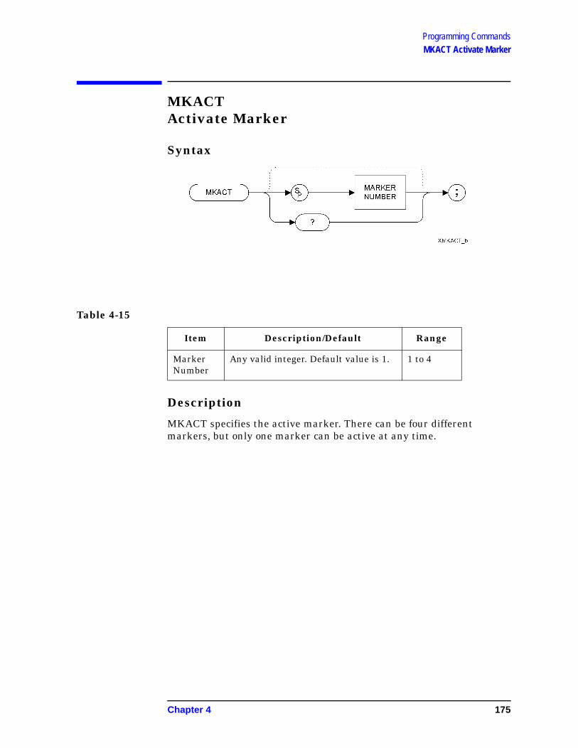
Programming CommandsMKACT Activate Marker
MKACTActivate Marker
Syntax
Description
MKACT specifies the active marker. There can be four different markers, but only one marker can be active at any time.
Table 4-15
Item Description/Default Range
Marker Number
Any valid integer. Default value is 1. 1 to 4
Chapter 4 175
Programming CommandsMKCF Marker to Center Frequency
MKCFMarker to Center Frequency
Syntax
Description
Sets the center frequency equal to the marker frequency and moves the marker to the center of the screen.
NOTE The functions of the MKCF command are identical to the E2 command (page 105).
176 Chapter 4

Programming CommandsMKD Marker Delta
MKDMarker Delta
Syntax
Step Increment: by 1/10 of the frequency span
Description
The MKD command computes the frequency and amplitude difference of the active marker and the delta marker. These values are displayed in the screen.
If a delta marker is not displayed on the screen, the MKD command places one at the specified frequency or on the right hand edge of the display. If an active marker is not displayed on the screen, the MKD command places an active marker at the center of the screen.
NOTE The active marker is the number 1 marker unless otherwise specified by the MKACT command (page 175).
Chapter 4 177

Programming CommandsMKD Marker Delta
NOTE If the MKD command is executed with the marker noise function active (MKNOISE ON (page 184) or KSM (page 146)), the marker amplitude displayed and returned by the MKA? command (page 174) or the MA command (page 167) is the difference between the noise densities at the reference marker and at the delta marker.
If the MKD command is executed before marker noise has been activated, the marker noise amplitude that is displayed on the screen is the difference between the carrier wave power and the noise density at the delta marker position.
However, the value returned by an MKA? (page 174) command or by an MA command (page 167) will always be the difference between the noise densities at the two markers. That is, the values returned by MKA? and MA do not always agree with those displayed on the screen. These returned values will only be correct as long as there has been no change in either the delta marker or the marker noise on the front panel.
The nominal noise bandwidth to RBW ratio for the RBW filters used in the ESA-E series analyzers is 1.128 for RBWs of 1 kHz and higher, and 1.055 for RBWs of less than 1 kHz. The nominal ratio for PSA analyzers is 1.055 for all RBWs. The nominal ratio for the HP 8566 family of analyzers is 1.128 for RBWs 100 kHz and higher, and 1.114 for RBWs of 30kHz and lower.
NOTE The OA option only returns the current value to the controller. It does not set the active function.
NOTE The functions of the MKD command are identical to the M3 command (page 165).
178 Chapter 4

Programming CommandsMKF Marker Frequency
MKFMarker Frequency
Syntax
Description
Specifies the frequency value of the active marker.
The format of the returned data is determined by the TDF (Trace Data Format) (page 244) command and, if TDF B (binary data format) has been selected, by the MDS command (page 170).
Chapter 4 179

Programming CommandsMKFC Marker Counter
MKFCMarker Counter
Syntax
Description
Turns on or off the marker frequency counter. The resolution of the frequency marker counter is determined by the MKFCR command (page 181).
NOTE The functions of the MKFC command are identical to the MC0 [zero] command (page 168) and MC1 [one] command (page 169).
NOTE This command is not supported when the remote language is HP8566B.
180 Chapter 4

Programming CommandsMKFCR Marker Counter Resolution
MKFCRMarker Counter Resolution
Syntax
NOTE The marker counter can be specified in time units when operating in the time domain
Description
Sets the resolution of the marker frequency counter.
NOTE On PSA analyzers, setting the marker frequency resolution will cause the Gate Time to change. The Gate Time is calculated using the following formula:
For restrictions on the Gate Time, refer to the PSA User’s and Programmer’s Reference Guide.
NOTE The functions of the MKFCR command are identical to the KS= command (page 125).
NOTE This command is not supported when the remote language is HP8566B.
Gate Time 1Resolution Value-----------------------------------------=
Chapter 4 181

Programming CommandsMKMIN Marker Minimum
MKMINMarker Minimum
Syntax
Description
Moves the active marker to the minimum value detected.
182 Chapter 4

Programming CommandsMKN Marker Normal
MKNMarker Normal
Syntax
Step Increment: by 1/10 of the frequency span.
Description
The MKN command moves the active marker to the specified frequency. If the active marker has not been declared with MKACT, a normal marker is turned on and this active marker is assumed to be 1. If the active marker type is not currently normal (for example, it is delta or peak), the MKN command will change it to a normal marker.
NOTE The OA option only returns the current value to the controller. It does not set the active function.
NOTE The functions of the MKN command are identical to the M2 [two] command (page 164).
NOTE This command is not supported when the remote language is HP8568B.
Chapter 4 183

Programming CommandsMKNOISE Marker Noise
MKNOISEMarker Noise
Syntax
Description
Displays the average RMS noise density at the marker.
NOTE The functions of the MKNOISE command are identical to the KSM command (page 146) and the KSL command (page 144).
NOTE If an MKD command or an M3 command is executed with the marker noise function active, the marker amplitude displayed and returned by the MKA? command (page 174) or the MA command (page 167) is the difference between the noise densities at the reference marker and at the delta marker.
If an MKD command or an M3 command is executed before marker noise has been activated, the marker noise amplitude that is displayed on the screen is the difference between the carrier wave power and the noise density at the delta marker position.
However, the value returned by an MKA? (page 174) command or by an MA command (page 167) will always be the difference between the noise densities at the two markers. That is, the values returned by MKA? and MA do not always agree with those displayed on the screen. These returned values will only remain correct as long as there has been no change made to either the delta marker or the marker noise from the front panel.
The nominal noise bandwidth to RBW ratio for the RBW filters used in the ESA-E series analyzers is 1.128 for RBWs of 1 kHz and higher, and
184 Chapter 4

Programming CommandsMKNOISE Marker Noise
1.055 for RBWs of less than 1 kHz. The nominal ratio for PSA analyzers is 1.055 for all RBWs. The nominal ratio for the HP 8566 family of analyzers is 1.128 for RBWs 100 kHz and higher, and 1.114 for RBWs of 30kHz and lower.
Chapter 4 185

Programming CommandsMKOFF Marker Off
MKOFFMarker Off
Syntax
Description
Turns off either the active marker or all the markers. If the ALL parameter is omitted, only the active marker is turned off.
186 Chapter 4

Programming CommandsMKP Marker Position
MKPMarker Position
Syntax
Description
Places the active marker at the specified X co-ordinate.
Chapter 4 187

Programming CommandsMKPK Marker Peak
MKPKMarker Peak
Syntax
Description
The MKPK command is used to place a marker on the highest signal peak detected, or to move a marker from one signal peak to another. The secondary keywords determine which signal peak the marker is moved to.
NOTE When executing the MKPK command, it is important to know whether you have an active marker on the screen. The result of issuing an MKPK command depends on whether a marker is already active or not.
MKPK With no secondary keyword specified, the MKPK command moves the active marker to the highest signal peak. If no marker is active, a marker is activated at the highest signal peak. This is exactly the same as when the HI keyword is used.
MKPK HI Moves the active marker to the highest signal peak. If no marker is active, a marker is activated at the highest signal peak. ‘HI’ equates to ‘HIghest (signal peak)’.
MKPK NH If there is an active marker on the screen, the NH keyword causes the marker to move down to the next highest signal peak. If there is no active marker, the command will be ignored. ‘NH’ equates to ‘Next Highest (signal peak)’.
MKPK NR If there is an active marker on the screen, the NR keyword causes the marker to move to the next signal peak of a higher frequency. If there is no active marker,
188 Chapter 4

Programming CommandsMKPK Marker Peak
the command will be ignored. ‘NR’ equates to ‘Next Right (signal peak)’.
MKPK NL If there is an active marker on the screen, the NL keyword causes the marker to move to the next signal peak of a lower frequency. If there is no active marker, the command will be ignored. ‘NL’ equates to ‘Next Left (signal peak)’.
NOTE The MKPK command with parameters NH, NR, or NL is ignored if there is no active marker.
NOTE The functions of the MKPK command (no secondary keyword) and the MKPK HI command are identical to the E1 commands: (page 104).
NOTE The functions of the MKPK NH command are similar to the KSK command (page 142), except that KSK does not take into account either the marker peak excursion value or the threshold value. For more details on marker peak excursion, see the MKPX command (page 190). For more information on threshold, see the TH command (page 245).
Chapter 4 189

Programming CommandsMKPX Marker Peak Excursion
MKPXMarker Peak Excursion
Syntax
Preset State: 6 dB.
Step Increment: by 1 dB.
Description
Specifies the minimum signal excursion for the spectrum analyzer’s internal peak identification routine.
The default value is 6 dB. In this case, any signal with an excursion of less than 6 dB on either side of the marker would not be identified. Thus, if an MKPK NH command were to be executed on such a signal, the analyzer would not place a marker on this signal peak.
190 Chapter 4

Programming CommandsMKREAD Marker Readout
MKREADMarker Readout
Syntax
Description
Selects the type of active trace information displayed by the spectrum analyzer marker readout.
The MKREAD command can select the following types of active trace information:
FRQ frequency
SWT sweep time
IST inverse sweep time
PER period
NOTE The Inverse Sweep Time (IST) readout is only available when using a delta marker in zero span.
The results of the data depend on the MKREAD parameter and the
Chapter 4 191

Programming CommandsMKREAD Marker Readout
frequency span, and whether the marker delta function is used.
NOTE FFT (Fast Fourier Transform) is not available in the HP8566B/68B Code Compatibility option.
Table 4-16
MKREAD Type Non-Zero Span Non-Zero Span
Delta Zero Span Zero Span Delta
FRQ Reads frequency Reads delta frequency
N/A N/A
SWT Reads time since the start of sweep
Reads delta time between end points
Waveform measurements of detected modulation
Waveform measurements of detected modulation
IST N/A N/A N/A Computes frequency corresponding to delta of markers. Performs 1/ (T1 − T2)
PER Period of frequency
(Pulse measurement) delta time
N/A N/A
192 Chapter 4

Programming CommandsMKRL Marker to Reference Level
MKRLMarker to Reference Level
Syntax
Description
The MKRL command moves the active marker to the reference level.
NOTE The functions of the MKRL command are identical to the E4 command (page 107).
Chapter 4 193

Programming CommandsMKSP Marker to Span
MKSPMarker to Span
Syntax
Description
The MKSP command operates only when the delta marker is On (see MKD (page 177) or M3 (page 165).) When the delta marker is On and MKSP is executed, the delta marker and active marker determine the start and stop frequencies. The left marker specifies the start frequency, and the right marker specifies the stop frequency. If marker delta is Off, there is no operation.
NOTE If the active marker is not a delta marker, there is no change in its position.
NOTE The functions of the MKSP command are identical to the KSO command (page 151).
194 Chapter 4
Programming CommandsMKSS Marker to Step Size
MKSSMarker to Step Size
Syntax
Description
Sets the center-frequency step-size equal to the marker frequency. If the analyzer is in the delta mode, the step size is set to the frequency difference between the active and the delta marker.
NOTE When the marker is a delta marker, the functions of the MKSS command are identical to the E3 command (page 106).
Chapter 4 195
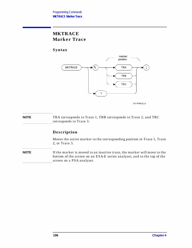
Programming CommandsMKTRACE Marker Trace
MKTRACEMarker Trace
Syntax
NOTE TRA corresponds to Trace 1, TRB corresponds to Trace 2, and TRC corresponds to Trace 3.
Description
Moves the active marker to the corresponding position in Trace 1, Trace 2, or Trace 3.
NOTE If the marker is moved to an inactive trace, the marker will move to the bottom of the screen on an ESA-E series analyzer, and to the top of the screen on a PSA analyzer.
196 Chapter 4

Programming CommandsMKTRACK Marker Track
MKTRACKMarker Track
Syntax
Description
Moves the signal on which the active marker is located to the center of the spectrum analyzer display and keeps the signal peak at center screen.
To keep a drifting signal at center screen, place the active marker on the desired signal before turning on MKTRACK.
NOTE The functions of the MKTRACK command are identical to the MT0 [zero] command (page 200) and the MT1 [one] command (page 201).
Chapter 4 197

Programming CommandsML Mixer Level
MLMixer Level
Syntax
Description
The ML command specifies the maximum signal level that is applied to the input mixer for a signal that is equal to or below the reference level.
The effective mixer level is equal to the reference level minus the input attenuator setting.
NOTE If an external amplifier gain value is set, the mixer level is determined using the following equation:
Mixer Level = Ref. Level - Attenuation + Ext. Amplifier Gain
The external amplifier gain is not preset by doing an IP command in case the analyzer is measuring a large signal. This is to protect the analyzer from damage from a large signal. For a helpful suggestion, see
198 Chapter 4

Programming CommandsML Mixer Level
Chapter 3 , “Hints and Tips,” on page 57.
NOTE The OA option only returns the current value to the controller. It does not set the active function.
NOTE The functions of the ML command are identical to the KS, command (page 124).
Chapter 4 199

Programming CommandsMT0 [zero] Marker Track Off
MT0 [zero]Marker Track Off
Syntax
Description
The MT0 [zero] command disables the marker tracking mode.
NOTE The functions of the MT0 [zero] command are identical to the MKTRACK OFF command (page 197).
200 Chapter 4
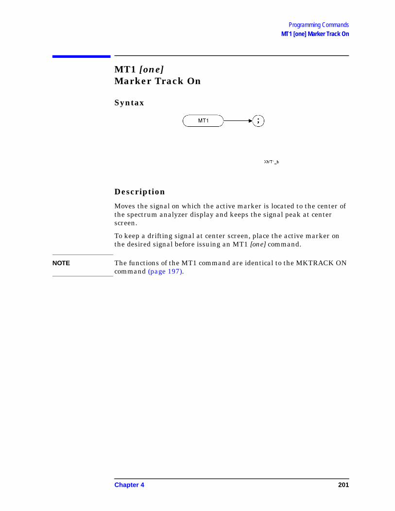
Programming CommandsMT1 [one] Marker Track On
MT1 [one]Marker Track On
Syntax
Description
Moves the signal on which the active marker is located to the center of the spectrum analyzer display and keeps the signal peak at center screen.
To keep a drifting signal at center screen, place the active marker on the desired signal before issuing an MT1 [one] command.
NOTE The functions of the MT1 command are identical to the MKTRACK ON command (page 197).
Chapter 4 201

Programming CommandsMXMH Maximum Hold
MXMHMaximum Hold
Syntax
Description
Updates each trace element with the maximum level detected.
MXMH updates the specified trace (either Trace A or Trace B) with a new value from a detector only if the new value is larger than the previous trace data value.
NOTE The functions of the MXMH command are identical to the A2 command (page 66)and B2 command (page 78).
202 Chapter 4

Programming CommandsO1 [one] Format - Display Units
O1 [one]Format - Display Units
Syntax
Description
The O1 [one] command transmits trace amplitude and position information as decimal values in display units.
Chapter 4 203

Programming CommandsO2 [two] Format - Two 8-Bit Bytes
O2 [two]Format - Two 8-Bit Bytes
Syntax
Description
The O2 [two] command transmits trace amplitude and position information as two 8-bit binary numbers, or one instruction word.
204 Chapter 4

Programming CommandsO3 [three] Format - Real Amplitude Units
O3 [three]Format - Real Amplitude Units
Syntax
Description
The O3 [three] command transmits trace amplitude information only, in measurement units of Hz, dBm, dB, volts or seconds.
Chapter 4 205

Programming CommandsO4 [four] Format - One 8-Bit Byte
O4 [four]Format - One 8-Bit Byte
Syntax
Description
The O4 [four] command transmits trace amplitude information only as a binary number.
206 Chapter 4

Programming CommandsOT Output Trace Annotations
OTOutput Trace Annotations
Syntax
Description
The OT command sends 32 character-strings to the controller. Each character-string can be up to 64 characters long.
NOTE The ‘dirty marker’ status report returned in string 27 is only supported in PSA series analyzers.
Chapter 4 207

Programming CommandsPEAKS Peaks
PEAKSPeaks
Syntax
Prerequisite Commands: TS when using trace data
Description
The PEAKS command sorts the signal peaks in the source trace by frequency or amplitude, and sends the results to destination trace.
208 Chapter 4
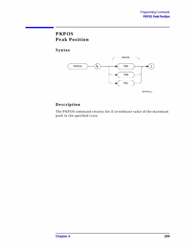
Programming CommandsPKPOS Peak Position
PKPOSPeak Position
Syntax
Description
The PKPOS command returns the X co-ordinate value of the maximum peak in the specified trace.
Chapter 4 209
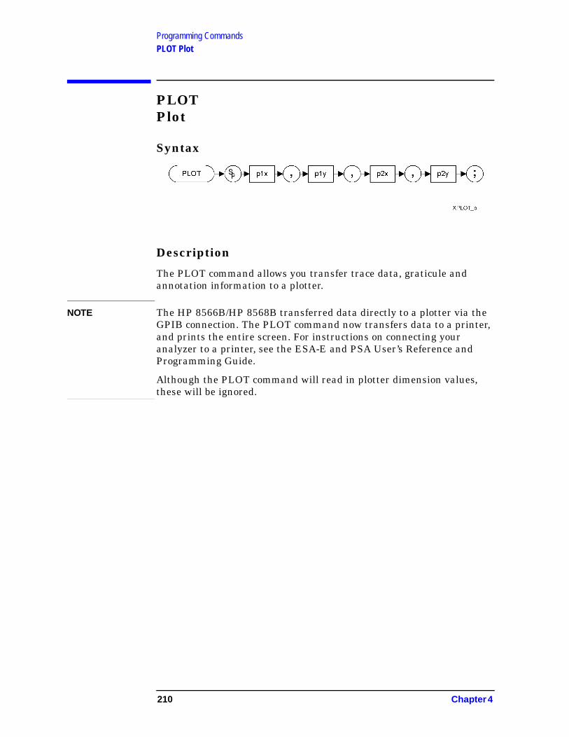
Programming CommandsPLOT Plot
PLOTPlot
Syntax
Description
The PLOT command allows you transfer trace data, graticule and annotation information to a plotter.
NOTE The HP 8566B/HP 8568B transferred data directly to a plotter via the GPIB connection. The PLOT command now transfers data to a printer, and prints the entire screen. For instructions on connecting your analyzer to a printer, see the ESA-E and PSA User’s Reference and Programming Guide.
Although the PLOT command will read in plotter dimension values, these will be ignored.
210 Chapter 4

Programming CommandsPP Preselector Peak
PPPreselector Peak
Syntax
Description
The PP command optimizes preselector tracking to peak the amplitude of a signal at the active marker. If a marker is not on the screen, PP places a marker at the highest signal level, and optimizes preselector tracking at that frequency.
NOTE This command is not supported when the remote language is HP8568B.
NOTE This command is only supported when the analyzer’s maximum frequency limit is greater than 3 GHz. If the command is issued on an analyzer with a maximum frequency limit of 3 GHz or less, an error message will be generated stating that the command is not supported.
Chapter 4 211

Programming CommandsPWRBW Power Bandwidth
PWRBWPower Bandwidth
Syntax
Description
The PWRBW command returns the bandwidth of the specified percentage of the total power.
The Command first computes the total power of all the signal responses contained within the trace array. It then repeatedly eliminates the trace element from each end of the trace array until the combined power of the remaining trace elements represents the specified percentage of the total power. The result is the frequency span, or power bandwidth, of these remaining trace elements.
The resulting bandwidth is therefore centered on the display, and not on the trace’s peak signal.
NOTE When this command is executed on an 8566, the trace stops. This is not the case when it is executed on either the ESA or the PSA analyzers.
212 Chapter 4

Programming CommandsR1 [one] Illegal Command SRQ
R1 [one]Illegal Command SRQ
Syntax
Description
The R1 [one] command deactivates all analyzer service requests (SRQs) except SRQ140, the illegal-command service request.
NOTE HP 8566B/68B Code Compatibility does not support the setting of bit 1 (units-key-pressed) of the status byte. Bit-1 of the status byte is always set to Off.
Chapter 4 213

Programming CommandsR2 [two] End-of-Sweep SRQ
R2 [two]End-of-Sweep SRQ
Syntax
Description
The R2 [two] command activates the end-of-sweep and illegal-command service requests.
NOTE HP 8566B/68B Code Compatibility does not support the setting of bit 1 (units-key-pressed) of the status byte. Bit-1 of the status byte is always set to Off.
214 Chapter 4

Programming CommandsR3 [three] Hardware Broken SRQ
R3 [three]Hardware Broken SRQ
Syntax
Description
The R3 [three] command activates the hardware-broken and illegal-command service requests.
NOTE HP 8566B/68B Code Compatibility does not support the setting of bit 1 (units-key-pressed) of the status byte. Bit-1 of the status byte is always set to Off.
Chapter 4 215

Programming CommandsR4 [four] Units-Key-Pressed SRQ
R4 [four]Units-Key-Pressed SRQ
Syntax
Description
The R4 [four] command activate the units-key-pressed and illegal-command SRQs.
NOTE ESA and PSA analyzers cannot replicate the units-key-pressed service request since no front panel interaction is supported.
NOTE HP 8566B/68B Code Compatibility does not support the setting of bit 1 (units-key-pressed) of the status byte. Bit-1 of the status byte is always set to Off.
216 Chapter 4

Programming CommandsRB Resolution Bandwidth
RBResolution Bandwidth
Syntax
Preset State: 3 MHz.
Step Increment: In a 1, 3, 10 series.
Description
The RB command specifies the resolution bandwidth. Available bandwidths are 10 Hz, 30 Hz, 300 Hz, 1 kHz, 3kHz, 30 kHz, 100 kHz, 300 kHz, 1 MHz, and 3 MHz. The resolution bandwidths, video bandwidths, and sweep time are normally coupled. Executing RB decouples them. Execute CR (page 94) to reestablish coupling.
NOTE The OA option only returns the current value to the controller. It does not set the active function.
NOTE Default values on ESA and PSA analyzers may vary from the HP 8566B and the HP 8568B analyzers. Refer to the relevant ESA-E or PSA User Guide to find out any restrictions that may apply.
Chapter 4 217

Programming CommandsRC Recall State
RCRecall State
Syntax
Description
Recalls analyzer state data from the specified state register in the analyzer’s memory.
Registers one through six are reserved for the user, and contain instrument states (such as front panel configuration) sorted with the SAVES command (page 228) or SV command (page 237).
NOTE Registers 7, 8 and 9 had specific uses in the HP8566B and HP 8568B analyzers. HP 8566B/68B Code Compatibility does not use these registers, so they are available for the your own use.
NOTE The functions of the RC command are identical to the RCLS command (page 219).
218 Chapter 4

Programming CommandsRCLS Recall State
RCLSRecall State
Syntax
Description
Recalls analyzer state data from the specified state register in the analyzer’s memory.
Registers one through six are reserved for the user, and contain instrument states (such as front panel configuration) sorted with the SAVES command (page 228) or SV command (page 237).
NOTE The functions of the RCLS command are identical to the RC command (page 218).
NOTE Registers 7, 8 and 9 had specific uses in the HP8566B and HP 8568B analyzers. HP 8566B/68B Code Compatibility does not use these registers, so they are available for the your own use.
Chapter 4 219

Programming CommandsREV Revision
REVRevision
Syntax
Description
The REV command returns the firmware revision number.
NOTE In ESA and PSA analyzers, this command returns the build date of Option 266 that you have installed in your analyzer. The date is returned in YYWW format where YY is the number of years since 1950, and WW is the Work Week.
As an example, if your Option 266 HP 8566B/68B Code Compatibility firmware was built on May 23 2002, the number 5221 would be returned. The year 2002 is 52 years after 1950, and May 23 is the 21st week of the year, hence 5221.
220 Chapter 4

Programming CommandsRL Reference Level
RLReference Level
Syntax
Description
Specifies the amplitude level of the top graticule line on the display. This represents the reference level.
CAUTION Signal levels above +30 dBm will damage the spectrum analyzer. For a helpful suggestion on this subject, see Chapter 3 , “Hints and Tips,” on page 57.
NOTE The OA option only returns the current value to the controller. It does not set the active function.
NOTE The Display Line is decoupled from the Reference Level. That is, if the display line is ON, changing the Reference Level does not change the
Chapter 4 221

Programming CommandsRL Reference Level
position of the Display Line, as would be the case when in SA mode.
For example, changing your Reference Level from -10 dB to 0.0 dB would change the Display Line from, for instance, -50 dB to -40 dB.
222 Chapter 4

Programming CommandsRMS Root Mean Square Value
RMSRoot Mean Square Value Returns the root mean square value of the trace in measurement units.
Syntax
Prerequisite Commands: TS when using trace data.
Description
Returns the RMS value of the trace in display units.
NOTE TRA corresponds to Trace 1, TRB corresponds to Trace 2, and TRC corresponds to Trace 3.
Chapter 4 223

Programming CommandsROFFSET Reference Level Offset
ROFFSETReference Level Offset
Syntax
Description
Offsets all amplitude readouts without affecting the trace.
Once activated, the ROFFSET command displays the amplitude offset on the left side of the screen.
Entering ROFFSET 0 or presetting the spectrum analyzer eliminates an amplitude offset.
NOTE The OA option only returns the current value to the controller. It does not set the active function.
NOTE The functions of the ROFFSET command are identical to the KSZ command (page 158).
224 Chapter 4

Programming CommandsRQS Service Request Mask
RQSService Request Mask
Syntax
Description
Sets a bit mask for service requests.
NOTE Some differences may be noticed in the value returned by the RQS query when compared with the value set. This is because Option 266 on ESA and PSA analyzers does not support the use of bit-1 of the status byte. Bit-1 of the status byte is always set to Off.
Chapter 4 225

Programming CommandsS1[one] Continuous Sweep
S1[one]Continuous Sweep
Syntax
Description
The S1 command sets the spectrum analyzer to continuous sweep mode. In the continuous sweep mode, the spectrum analyzer takes its next sweep as soon as possible after the current sweep (as long as the trigger conditions are met). A sweep may temporarily be interrupted by data entries made over the remote interface.
NOTE The functions of the command S1 are identical to the CONTS command (page 93).
226 Chapter 4

Programming CommandsS2 [two] Single Sweep
S2 [two]Single Sweep
Syntax
Description
The S2 command sets the analyzer to single sweep mode. Each subsequent time that the command S2 is sent, one sweep is started if the trigger conditions are met.
NOTE The functions of the S2 command are similar to the SNGLS command (page 230).
Chapter 4 227

Programming CommandsSAVES Save State
SAVESSave State
Syntax
Description
Saves the current state of the spectrum analyzer in any of the registers one through six.
NOTE Registers 7, 8 and 9 had specific uses in the HP8566B and HP 8568B analyzers. HP 8566B/68B Code Compatibility does not use these registers, so they are available for the your own use.
NOTE The functions of the SAVES command are identical to the SV command (page 237).
228 Chapter 4

Programming CommandsSMOOTH Smooth Trace
SMOOTHSmooth Trace
Syntax
Prerequisite Commands: TS when using trace data.
Description
Smooths the trace according to the number of points specified for the running average.
Each point value is replaced with the average of the values (in measurement units) of the given number of points centered on it. Increasing the number of points increases smoothing at the cost of decreasing resolution. If the number of points is an even number, then the number of points is increased by one. If the number of points is larger than the size of SOURCE, then the size of SOURCE is used (unless size of SOURCE is even, in which case the size of SOURCE minus one is used). Smoothing decreases at the endpoints.
NOTE Some differences may be noticed between the smoothed trace in HP8566B/68B analyzers and the smoothed trace using the same signal in ESA-E and PSA analyzers.
Chapter 4 229

Programming CommandsSNGLS Single Sweep
SNGLSSingle Sweep
Syntax
Description
Sets the spectrum analyzer to single-sweep mode. Each time TS (take sweep) is sent, one sweep taken as long as the trigger conditions are met.
NOTE The functions of the SNGLS command are similar to the S2 command (page 227).
230 Chapter 4
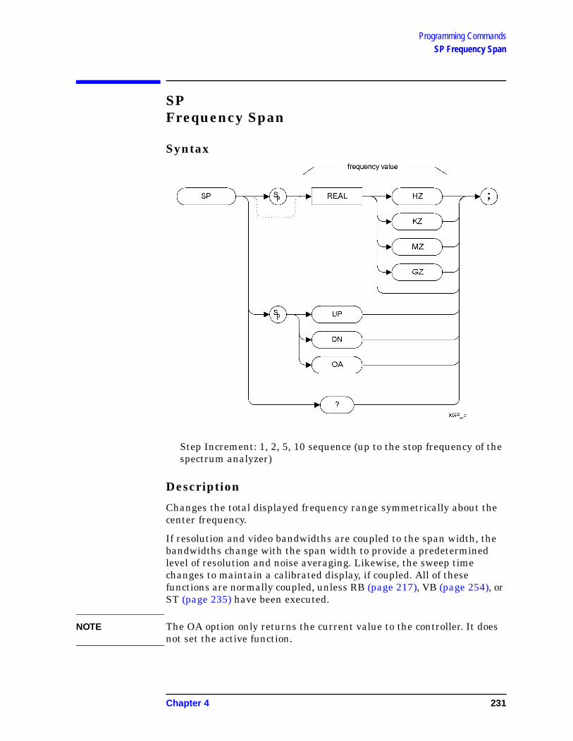
Programming CommandsSP Frequency Span
SPFrequency Span
Syntax
Step Increment: 1, 2, 5, 10 sequence (up to the stop frequency of the spectrum analyzer)
Description
Changes the total displayed frequency range symmetrically about the center frequency.
If resolution and video bandwidths are coupled to the span width, the bandwidths change with the span width to provide a predetermined level of resolution and noise averaging. Likewise, the sweep time changes to maintain a calibrated display, if coupled. All of these functions are normally coupled, unless RB (page 217), VB (page 254), or ST (page 235) have been executed.
NOTE The OA option only returns the current value to the controller. It does not set the active function.
Chapter 4 231

Programming CommandsSP Frequency Span
NOTE HP 8566B/68B Code Compatibility does not mimic the exact coupling behavior of the HP8566B or HP8568B analyzers. Refer to your ESA - or PSA User’s and Programmer’s Reference Guide for the values used.
232 Chapter 4

Programming CommandsSRQ User-Defined SRQ
SRQUser-Defined SRQ
Syntax
Description
The SRQ command sends a service request to the controller when the SRQ operand fits the mask supplied with the RQS command.
NOTE HP 8566B/68B Code Compatibility does not support the setting of bit 1 (units-key-pressed) of the status byte. Bit-1 of the status byte is always set to Off
Chapter 4 233

Programming CommandsSS Center Frequency Step Size
SSCenter Frequency Step Size
Syntax
Description
Specifies center frequency step size.
NOTE The OA option only returns the current value to the controller. It does not set the active function.
234 Chapter 4

Programming CommandsST Sweep Time
STSweep Time
Syntax
Description
The ST command specifies the time in which the analyzer sweeps the displayed frequency or time span.
NOTE The ST OA command and the ST? command both return the current value to the controller. However, the ST OA command does not set the active function to be Sweep Time.
Chapter 4 235

Programming CommandsSTDEV Standard Deviation of Trace Amplitudes
STDEVStandard Deviation of Trace Amplitudes
Syntax
Prerequisite Commands: TS when using trace data
NOTE TRA corresponds to Trace 1, TRB corresponds to Trace 2, and TRC corresponds to Trace 3.
Description
Returns the standard deviation of the trace amplitude in display units.
236 Chapter 4

Programming CommandsSV Save State
SVSave State
Syntax
Description
Saves the current state of the spectrum analyzer in any of the registers one through six.
NOTE Registers 7, 8 and 9 had specific uses in the HP8566B and HP 8568B analyzers. HP 8566B/68B Code Compatibility does not use these registers, so they are available for the your own use.
NOTE The functions of the SV command are identical to the SAVES command (page 228).
Chapter 4 237

Programming CommandsT1 [one] Free Run Trigger
T1 [one]Free Run Trigger
Syntax
Description
The T1 [one] command sets the analyzer sweep to free run trigger mode.
NOTE The functions of the T1 [one] command are identical to the TM FREE command (page 246).
238 Chapter 4

Programming CommandsT2 [two] Line Trigger
T2 [two]Line Trigger
Syntax
Description
The T2 [two] command sets the analyzer sweep to line trigger mode.
NOTE The functions of the T2 [two] command are identical to the TM LINE command (page 246).
Chapter 4 239

Programming CommandsT3 [three] External Trigger
T3 [three]External Trigger
Syntax
Description
The T3 [three] command sets the analyzer sweep to external trigger mode.
NOTE The functions of the T3 [three] command are identical to the TM EXT command (page 246).
240 Chapter 4

Programming CommandsT4 [four] Video Trigger
T4 [four]Video Trigger
Syntax
Description
The T4 [four] command sets the analyzer sweep to video trigger mode.
NOTE The functions of the T4 [four] command are identical to the TM VID command (page 246).
Chapter 4 241

Programming CommandsTA Trace A
TATrace A
Syntax
Description
Returns trace A amplitude values from the analyzer to the controller.
The display unit values are transferred in sequential order (from left to right) as seen on the screen. Display unit values can be transferred to the controller in any one of the four output formats as determined by the O1 [one] (page 203), O2 [two] (page 204), O3 [three] (page 205) and O4 [four] commands (page 206). The format of the returned data is also affected by the TDF (Trace Data Format) (page 244) command and, if TDF B (binary data format) has been selected, by the MDS command (page 170).
242 Chapter 4

Programming CommandsTB Trace B
TBTrace B
Syntax
Description
Returns trace B amplitude values from the analyzer to the controller.
The display unit values are transferred in sequential order (from left to right) as seen on the screen. Display unit values can be transferred to the controller in any one of the four output formats as determined by the O1 [one] (page 203), O2 [two] (page 204), O3 [three] (page 205) and O4 [four] commands (page 206). The format of the returned data is also affected by the TDF (Trace Data Format) (page 244) command and, if TDF B (binary data format) has been selected, by the MDS command (page 170).
Chapter 4 243

Programming CommandsTDF Trace Data Format
TDFTrace Data Format
Syntax
Description
Formats trace information for return to the controller.
The different trace data formats are as follows:
• Specifying M enables the 01 format and returns values in display units, from 0 to 1001.
• Specifying P enables the 03 format and returns absolute measurement values, such as dBm or Hz.
• Specifying A returns data as an A-block data field. The MDS command determines whether data comprises one or two 8-bit bytes. (See MDS (page 170))
• Specifying I returns data as an I-block data field. The MDS command determines whether data comprises one or two 8-bit bytes. (See MDS (page 170))
• Specifying B enables the 02 or 04 format. The MDS command determines whether data comprises one or two 8-bit bytes
244 Chapter 4

Programming CommandsTH Threshold
THThreshold
Syntax
Description
The TH command blanks signal responses below the threshold level, similar to a base line clipper. The threshold level is nine major divisions below the reference level, unless otherwise specified. The UP and DN commands move the threshold 10 dB.
NOTE The OA option only returns the current value to the controller. It does not set the active function.
NOTE The HP 8566B and HP 8568B both blank the display of everything below the threshold level, but this is not the case with ESA and PSA analyzers. Using the PEAKS (page 208) and MKPK (page 188) commands causes any values below the threshold level to be disregarded, even though the full trace will still be displayed.
Chapter 4 245

Programming CommandsTM Trigger Mode
TM Trigger Mode
Syntax
Description
Selects a trigger mode: free, line, video, or external.
NOTE The functions of the TM command are identical to the T1 (page 238), T2 (page 239), T3 (page 240) and T4 (page 241) commands.
246 Chapter 4

Programming CommandsTRA Trace Data Input and Output
TRATrace Data Input and Output
Syntax
Description
The TRA command transfers Trace A amplitude values from the analyzer to the controller. The units are display units, and the format depends on the trace data format selected.
Chapter 4 247

Programming CommandsTRB Trace Data Input and Output
TRBTrace Data Input and Output
Syntax
Description
The TRB command transfers Trace B amplitude values from the analyzer to the controller. The units are display units, and the format depends on the trace data format selected.
248 Chapter 4

Programming CommandsTRDSP Trace Display
TRDSPTrace Display
Syntax
Description
The TRDSP command turns the display of the specified trace on or off.
Chapter 4 249

Programming CommandsTRSTAT Trace State
TRSTATTrace State
Syntax
Description
The TRSTAT command returns trace states to the controller. Valid trace states are Clear-write, View, and Blank.
250 Chapter 4

Programming CommandsTS Take Sweep
TSTake Sweep
Syntax
Description
Starts and completes one full sweep before the next command is executed.
A take sweep is required for each sweep in the single-sweep mode. TS prevents further input from the interface bus until the sweep is completed to allow synchronization with other instruments.
Chapter 4 251

Programming CommandsVAVG Video Average
VAVGVideo Average
Syntax
Description
Enables the video-averaging function, which averages trace points to smooth the displayed trace. When queried, the VAVG command returns the average length.
Before executing the VAVG command, select Trace A or Trace B as the active trace (CLRW command (page 92)) and blank the remaining trace.
NOTE The functions of the VAVG command are identical to the KSG command (page 136) and KSH command (page 138).
NOTE There are a few differences in the way video averaging works in HP 8566B/68B Code Compatibility compared to the original spectrum analyzers. See the table below for a summary of these differences.
Table 4-17 Video Averaging Behavioral Differences
Condition Original HP 8566B and HP 8568B Spectrum Analyzers
HP 8566B/68B Code Compatibility Option
Change in center frequency or span
In single sweep mode, resets counter to zero and starts the averaging again
In single sweep mode, resets counter to zero and starts the averaging again
252 Chapter 4

Programming CommandsVAVG Video Average
Change in resolution bandwidth, video bandwidth, sweep time, reference level or attenuation
In single sweep mode, resets counter to zero and starts the averaging again
Continues the measurement without resetting the counter.
Change in average counter setting to a higher value
Continues counting from where the previous value left off
Resets the counter to zero and starts the measurement again
Change in average counter setting to a lower value
Updates the screen annotation with the lower averaging value
Resets the counter to zero and starts the measurement again
All conditions Original trace is displayed in Trace C
Only displays the averaged trace. The averaged trace is displayed in Trace A
Averaging turned on Sweep time remains unchanged
Sweep time changes due to the selection of the sample detector
Table 4-17 Video Averaging Behavioral Differences
Condition Original HP 8566B and HP 8568B Spectrum Analyzers
HP 8566B/68B Code Compatibility Option
Chapter 4 253

Programming CommandsVB Video Bandwidth
VBVideo Bandwidth
Syntax
Description
Specifies the video bandwidth, which is a post-detection, low-pass filter.
NOTE The OA option only returns the current value to the controller. It does not set the active function.
NOTE Default values on the ESA and PSA analyzers may differ from the HP 8566B and HP 8568B analyzers. Refer to the relevant ESA and PSA User’s and Programmer’s Reference Guides for more details on the restrictions on the video bandwidth range.
When auto coupled, the video bandwidth is calculated as Resolution Bandwidth x Video:Resolution Bandwidth Ratio
254 Chapter 4

Programming CommandsVBO Video Bandwidth Coupling Offset
VBOVideo Bandwidth Coupling Offset
Syntax
Description
The VBO command specifies the relationship between the video and resolution bandwidths which is maintained when these bandwidths are coupled. The bandwidths are usually coupled unless the RB command (page 217) or VB command (page 254) have been executed.
• When 0 is selected, the ratio remains fixed at 1. That is, the resolution bandwidth and the video bandwidth are always equal
• When 1 is selected, the video bandwidth is one step higher than the resolution bandwidth. That is, the video bandwidth:resolution bandwidth ratio is three.
• When -1 is selected, the video bandwidth is one step lower than the resolution bandwidth. That is, the video bandwidth:resolution bandwidth ratio is 0.3.
Chapter 4 255

Programming CommandsVIEW View Trace
VIEWView Trace
Syntax
Description
Displays Trace A, trace B, or trace C, and stops taking new data into the viewed trace.
NOTE The functions of the VIEW command are identical to the A3 (page 67), B3 (page 79) and KSj (page 141) commands.
NOTE TRA corresponds to Trace 1, TRB corresponds to Trace 2, and TRC corresponds to Trace 3.
256 Chapter 4

Programming CommandsXCH Exchange
XCHExchange
Syntax
Description
The XCH command exchanges the contents of the source and destination traces. The traces are analyzed and adjusted to fit the number of display points on the screen which is typically 1001 points.
NOTE The functions of the XCH TRA,TRB command are identical to the AXB (page 76) and EX (page 109) commands.
The functions of the XCH TRB,TRC command are identical to the BXC (page 85) and KSi (page 140) commands.
Chapter 4 257

Programming CommandsXCH Exchange
258 Chapter 4

5 A Brief Introduction to the SCPI Language
259

A Brief Introduction to the SCPI LanguageSCPI Language Basics
SCPI Language BasicsThis section is not intended to teach you everything about the SCPI (Standard Commands for Programmable Instruments) programming language. The SCPI Consortium or IEEE can provide that level of detailed information.
Topics covered in this chapter include:
• “Creating Valid Commands” on page 5-261
• “Command Keywords and Syntax” on page 5-260
• “Special Characters in Commands” on page 5-262
• “Parameters in Commands” on page 5-263
• “Putting Multiple Commands on the Same Line” on page 5-265
For more information refer to:
IEEE Standard 488.1-1987, IEEE Standard Digital Interface for Programmable Instrumentation. New York, NY, 1998.
IEEE Standard 488.2-1987, IEEE Standard Codes, Formats, Protocols and Comment Commands for Use with ANSI/IEEE Std488.1-1987. New York, NY, 1998.
Command Keywords and Syntax
A typical command is made up of keywords set off by colons. The keywords are followed by parameters that can be followed by optional units.
Example: SENSe:FREQuency:STARt 1.5 MHZ
The instrument does not distinguish between upper and lower case letters. In the documentation, upper case letters indicate the short form of the keyword. The lower case letters, indicate the long form of the keyword. Either form may be used in the command.
Example: Sens:Freq:Star 1.5 mhz
is the same as SENSE:FREQ:start 1.5 MHz
NOTE The command SENS:FREQU:STAR is not valid because FREQU is neither the short, nor the long form of the command. Only the short and long forms of the keywords are allowed in valid commands.
260 Chapter 5
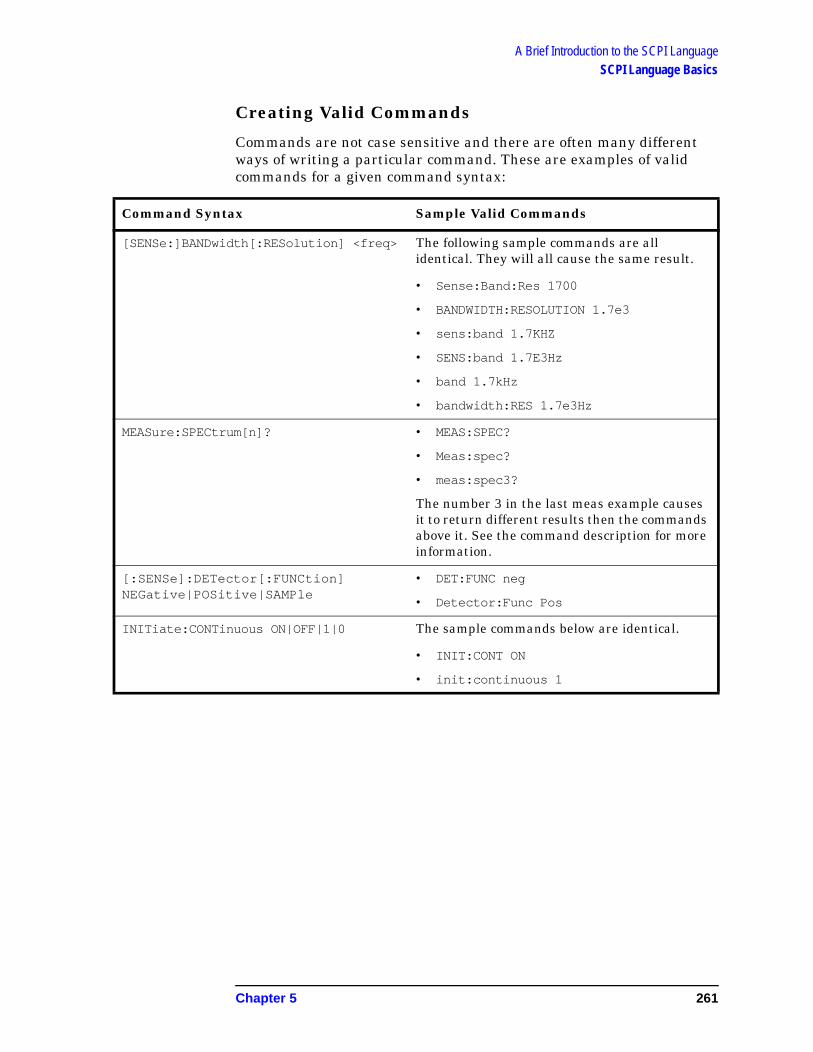
A Brief Introduction to the SCPI LanguageSCPI Language Basics
Creating Valid Commands
Commands are not case sensitive and there are often many different ways of writing a particular command. These are examples of valid commands for a given command syntax:
Command Syntax Sample Valid Commands
[SENSe:]BANDwidth[:RESolution] <freq> The following sample commands are all identical. They will all cause the same result.
• Sense:Band:Res 1700
• BANDWIDTH:RESOLUTION 1.7e3
• sens:band 1.7KHZ
• SENS:band 1.7E3Hz
• band 1.7kHz
• bandwidth:RES 1.7e3Hz
MEASure:SPECtrum[n]? • MEAS:SPEC?
• Meas:spec?
• meas:spec3?
The number 3 in the last meas example causes it to return different results then the commands above it. See the command description for more information.
[:SENSe]:DETector[:FUNCtion] NEGative|POSitive|SAMPle
• DET:FUNC neg
• Detector:Func Pos
INITiate:CONTinuous ON|OFF|1|0 The sample commands below are identical.
• INIT:CONT ON
• init:continuous 1
Chapter 5 261

A Brief Introduction to the SCPI LanguageSCPI Language Basics
Special Characters in Commands
Special Character
Meaning Example
| A vertical stroke between parameters indicates alternative choices. The effect of the command is different depending on which parameter is selected.
Command: TRIGger:SOURce EXTernal|INTernal|LINE
The choices are external, internal, and line.Ex: TRIG:SOURCE INT
is one possible command choice.
A vertical stroke between keywords indicates identical effects exist for both keywords. The command functions the same for either keyword. Only one of these keywords is used at a time.
Command: SENSe:BANDwidth|BWIDth:OFFSet
Two identical commands are: Ex1: SENSE:BWIDTH:OFFSET Ex2: SENSE:BAND:OFFSET
[ ] keywords in square brackets are optional when composing the command. These implied keywords will be executed even if they are omitted.
Command: [SENSe:]BANDwidth[:RESolution]:AUTO
The following commands are all valid and have identical effects:Ex1: bandwidth:autoEx2: band:resolution:autoEx3: sense:bandwidth:auto
< > Angle brackets around a word, or words, indicates they are not to be used literally in the command. They represent the needed item.
Command:SENS:FREQ <freq>
In this command example the word <freq> should be replaced by an actual frequency.
Ex: SENS:FREQ 9.7MHz.
{ } Parameters in braces can optionally be used in the command either not at all, once, or several times.
Command:MEASure:BW <freq>{,level}
A valid command is:meas:BW 6 MHz, 3dB, 60dB
262 Chapter 5

A Brief Introduction to the SCPI LanguageSCPI Language Basics
Parameters in Commands
There are four basic types of parameters: booleans, keywords, variables and arbitrary block program data.
OFF|ON|0|1(Boolean) This is a two state boolean-type parameter. The
numeric value 0 is equivalent to OFF. Any numeric value other than 0 is equivalent to ON. The numeric values of 0 or 1 are commonly used in the command instead of OFF or ON. Queries of the parameter always return a numeric value of 0 or 1.
keyword The keywords that are allowed for a particular command are defined in the command syntax description.
Units Numeric variables may include units. The valid units for a command depend on the variable type being used. See the following variable descriptions. The indicated default units will be used if no units are sent. Units can follow the numerical value with, or without, a space.
Variable A variable can be entered in exponential format as well as standard numeric format. The appropriate range of the variable and its optional units are defined in the command description.
The following keywords may also be used in commands, but not all commands allow keyword variables.
• DEFault - resets the parameter to its default value.
• UP - increments the parameter.
• DOWN - decrements the parameter.
• MINimum - sets the parameter to the smallest possible value.
• MAXimum - sets the parameter to the largest possible value.
The numeric value for the function’s MINimum, MAXimum, or DEFault can be queried by adding the keyword to the command in its query form. The keyword must be entered following the question mark.
Example query: SENSE:FREQ:CENTER? MAX
Chapter 5 263

A Brief Introduction to the SCPI LanguageSCPI Language Basics
Variable Parameters
<freq><bandwidth> Is a positive rational number followed by optional units.
The default unit is Hz. Acceptable units include: HZ, KHZ, MHZ, GHZ.
<time><seconds> Is a rational number followed by optional units. The
default units are seconds. Acceptable units include: S, MS, US.
<voltage> Is a rational number followed by optional units. The default units are V. Acceptable units include: Volts, V, MV, UV.
<power><ampl> Is a rational number followed by optional units. The
default units are dBm. Acceptable units include: DBM, DBMV, W.
<rel_power><rel_ampl> Is a positive rational number followed by optional units.
The default units are dB. Acceptable units include: DB.
<angle><degrees> Is a rational number followed by optional units. The
default units are degrees. Acceptable units include: DEG, RAD.
<integer> An integer value has no units.
<real> Is a floating point number, with no units.
<percent> Is a rational number between 0 and 100, with no units.
<string> Is a series of alpha numeric characters.
<bit_pattern> Specifies a series of bits rather than a numeric value. The bit series is the binary representation of a numeric value. There are no units.
Bit patterns are most often specified as hexadecimal numbers, though octal, binary or decimal numbers may also be used. In the SCPI language these numbers are specified as:
• Hexadecimal, #Hdddd or #hdddd where ‘d’ represents a hexadecimal digit 0 to 9 and ‘a’ to ‘f ’. So #h14 can be used instead of the decimal number 20.
• Octal, #Odddddd or #odddddd where ‘d’ represents an octal digit 0 to 7. So #o24 can be used instead of the decimal number 20.
264 Chapter 5

A Brief Introduction to the SCPI LanguageSCPI Language Basics
• Binary, #Bdddddddddddddddd or #bdddddddddddddddd where ‘d’ represents a 1 or 0. So #b10100 can be used instead of the decimal number 20.
Block Program Data
Some parameters consist of a block of data. Block data There are a few standard types of block data. Arbitrary blocks of program data can also be used.
<trace> Is an array of rational numbers corresponding to displayed trace data. See FORMat:DATA for information about available data formats.
A SCPI command often refers to a block of current trace data with a variable name such as: Trace1, TRACE2, or trace3, depending on which trace is being accessed.
<arbitrary block data> Consists of a block of data bytes. The first information sent in the block is an ASCII header beginning with #. The block is terminated with a semi-colon. The header can be used to determine how many bytes are in the data block. There are no units.
For example, suppose the header is #512320.
• The first digit in the header (5) tells you how many additional digits/bytes there are in the header.
• The 12320 means 12 thousand, 3 hundred, 20 data bytes follow the header.
• Divide this number of bytes by your current data format (bytes/data point), either 8 (for real64), or 4 (for real32). For this example, if you’re using real64 then there are 1540 points in the block.
Putting Multiple Commands on the Same Line
Multiple commands can be written on the same line, reducing your code space requirement. To do this:
• Commands must be separated with a semicolon (;).
• If the commands are in different subsystems, the key word for the new subsystem must be preceded by a colon (:).
• If the commands are in the same subsystem, the full hierarchy of the command key words need not be included. The second command can start at the same key word level as the command that was just executed.
Chapter 5 265

A Brief Introduction to the SCPI LanguageSCPI Language Basics
SCPI Termination and Separator Syntax
A terminator must be provided when an instrument is controlled using RS-232. There are several issues to be understood about choosing the proper SCPI terminator and separator when this is the case. There is no current SCPI standard for RS-232. Although one intent of SCPI is to be interface independent, <END> is only defined for IEEE 488 operation. At the time of this writing, the RS-232 terminator issue was in the process of being addressed in IEEE standard 1174.
A semicolon (;) is not a SCPI terminator, it is a separator. The purpose of the separator is to queue multiple commands or queries in order to obtain multiple actions and/or responses. Make sure that you do not attempt to use the semicolon as a terminator when using RS-232 control.
All binary trace and response data is terminated with <NL><END>, as defined in Section 8.5 of IEEE Standard 488.2-1992, IEEE Standard Codes, Formats, Protocols and Common Commands for Use with ANSI/IEEE Std 488.1-1987. New York, NY, 1992.
The following are some examples of good and bad commands. The examples are created from a theoretical instrument with the simple set of commands indicated below:
[:SENSe]:POWer
[:RF]:ATTenuation 40dB
:TRIGger [:SEQuence]:EXTernal [1]
:SLOPePOSitive
[:SENSe]:FREQuency
:STARt:POWer[:RF]
:MIXer:RANGe[:UPPer]
266 Chapter 5

A Brief Introduction to the SCPI LanguageSCPI Language Basics
Bad Command Good Command
PWR:ATT 40dB POW:ATT 40dB
The short form of POWER is POW, not PWR.
FREQ:STAR 30MHz;MIX:RANG -20dBm
FREQ:STAR 30MHz;POW:MIX:RANG -20dBm
The MIX:RANG command is in the same :SENSE subsystem as FREQ, but executing the FREQ command puts you back at the SENSE level. You must specify POW to get to the MIX:RANG command.
FREQ:STAR 30MHz;POW:MIX RANG -20dBm
FREQ:STAR 30MHz;POW:MIX:RANG -20dBm
MIX and RANG require a colon to separate them.
:POW:ATT 40dB;TRIG:FREQ:STAR 2.3GHz
:POW:ATT 40dB;:FREQ:STAR 2.3GHz
:FREQ:STAR is in the :SENSE subsystem, not the :TRIGGER subsystem.
:POW:ATT?:FREQ:STAR? :POW:ATT?;:FREQ:STAR?
:POW and FREQ are within the same :SENSE subsystem, but they are two separate commands, so they should be separated with a semicolon, not a colon.
:POW:ATT -5dB;:FREQ:STAR 10MHz
:POW:ATT 5dB;:FREQ:STAR 10MHz
Attenuation cannot be a negative value.
Chapter 5 267

A Brief Introduction to the SCPI LanguageSCPI Language Basics
268 Chapter 5

Index
AA minus B
into A, 69, 87off, 86plus display line, 70
A plus Bto A, 72, 131
A1, 35, 65A2, 35, 66A3, 35, 67A4, 35, 68ABS, 35AC coupling, 120AC/DC, 118, 120activate marker, 175ADD, 35address
display, 98AMB, 35, 69AMBPL, 35, 70amplitude
in dBm, 126in dBmV, 128in dBuv, 130in volts, 132
amplitude marker, 174amplitude units, 63, 75analyzer command, 63angle parameter (variables), 264ANNOT, 35, 71annotation, 71
off, 152on, 153, 154output trace, 207
APB, 35, 72arbitrary block data, 265AT, 17, 35, 73attenuation, 73
coupling, 88AUNITS, 35, 75average noise density at the
markerMKNOISE, 184
AVG, 35AXB, 76
BB minus display line, 81B1, 35, 77B2, 36, 78B3, 36, 79B4, 36, 80bandwidth
percent of total power expressed as, 212
video, 254video coupling offset, 255
bit_pattern parameter (variables), 264
BL, 36, 81BLANK, 36, 82blank
trace C, 143blank trace, 68, 80, 82block data
arbitrary, 265identifying block size, 265parsing output, 265
BML, 36, 83boolean parameter (commands),
263BRD, 36BTC, 36, 84BWR, 36BXC, 36, 85
CC1, 36, 86C2, 36, 87CA, 36, 88center frequency, 89
marker, 176center frequency marker, 105center frequency step size, 234CF, 17, 36, 89changing the video bandwidth
VB, 254Chapter 6 , “A Brief Introduction
to the SCPI Language,” on page 247, 28
character EOI, 63characters, 62clear average, 91Clear Command Error Log, 16clear write, 65, 77, 92CLRAVG, 37, 91CLRW, 37, 92Cmd Error Log, 16CNVLOSS, 37Command Err, 15command mnemonic, 62command terminators, 62commands
boolean parameter, 263differences, 17, 26keyword parameter, 263multiple on a line, 265parameters, 263syntax, 260termination, IEEE, 266units parameter, 263valid commands, 261variable parameter, 263
variable parameter keywords, 263
COMPRESS, 37CONCAT, 37configure remote language, 15continuous sweep, 93, 226controlling the marker counter,
180CONTS, 37, 93couple
frequency step size, 95resolution bandwidth, 94sweep time, 96video bandwidth, 97
couple attenuation, 88coupling
AC/DC, 118, 120video bandwidth offset, 255
CR, 37, 94CS, 37, 95CT, 37, 96CTA, 37CTM, 37current units, 63CV, 37, 97
DD1, 37D2, 37D3, 38DA, 38, 98data
arbitrary blocks, 265data byte, 63data byte EOI, 63data format
display units, 203one 8-bit byte, 206real amplitude units, 205trace, 244two 8-bit bytes, 204
DC coupling, 118DD, 38degree parameter (variables), 264deleting an
application/personality, 4, 9delimiter, 63delta marker, 165, 177delta marker step size, 106DET, 17, 38, 99detection
negative peak, 133normal, 127positive peak, 129sample, 135
detection mode, 99digit, 63
269

Index
display address, 98display line, 101display line enable, 102display line off, 159display off, 137display on, 139display trace, 249DISPOSE, 38DIV, 38DL, 17, 38, 101DLE, 38, 102documentation
option, 31DONE, 38, 103dotted lines
optional path, 62DR, 38DSPLY, 38DT, 38DW, 38
EE1, 38, 104E2, 38, 105E3, 39, 106E4, 39, 107EE, 39EK, 39ELSE, 39EM, 39enable display line, 102ENDIF, 39end-of-sweep SRQ, 214ENTER, 39ERASE, 39ERR, 39, 108error codes
list of, 108errors
clearing, 16displaying, 15storing, 16
EX, 39, 109exchange traces, 257
A and B, 76, 109B and C, 85, 140
excursionmarker peak, 190
EXP, 39external trigger, 156, 240external trigger mode, 246EXTMXR, 39
FFA, 17, 39, 110fast preselector peak, 114FB, 17, 39, 111
FFT, 40FFTKNL, 40FOFFSET, 18, 40, 112format
display units, 203one 8-bit byte, 206real amplitude units, 205trace data, 244two 8-bit bytes, 204
FPKA, 18, 26, 40, 114free run trigger, 238free trigger mode, 246frequency
center, 89marker, 179marker readout, 191offset, 112start, 110stop, 111
frequency offset, 155frequency parameter (variables),
264frequency span, 231frequency step size
coupling, 95frequency units, 63FS, 40, 115FULBAND, 40full span, 115FUNCDEF, 40
Ggetting started, 2GR, 40GRAT, 40, 117graticule, 117graticule off, 148Graticule on, 150
Hhardware broken SRQ, 215hardware requirements, 3HD, 40hints, 58
compatibility, 58instrument presets, 59overloading, 59SCPI language, 59speed, 58sweep times, 58synchronization, 58, 59time out, 58
HNLOCK, 40HNUNLK, 40HP8566B remote language, 15HP8568B remote language, 15
II1, 18, 26, 40, 118I2, 18, 26, 41, 120IB, 41ID, 41, 122identify, 122IDSTAT, 41IEEE command termination, 266IF, 41IFTKNL, 41illegal command SRQ, 213impedance units, 63installation disk set, 4installer troubleshooting, 8installing measurement
personalities, 4, 9instrument preset, 123INT, 41integer variable (variables), 264IP, 41, 123
KKEYDEF, 41KEYEXC, 41keyword parameter (commands),
263KS#, 41KS(, 41KS), 41KS,, 18, 42, 124KS/, 42KS<, 42KS=, 19, 26, 42, 125KS>, 42KS|, 42KS123, 42KS125, 42KS126, 42KS127, 42KS39, 42KS43, 42KS91, 42KS92, 42KS94, 43KSA, 43, 126KSa, 19, 43, 127KSB, 43, 128KSb, 43, 129KSC, 43, 130KSc, 43, 131KSD, 43, 132KSd, 43, 133KSE, 19, 43, 134KSe, 43, 135KSF, 43KSf, 43KSG, 19, 43, 136
270

Index
KSg, 43, 137KSH, 43, 138KSh, 44, 139KSI, 44KSi, 44, 140KSJ, 44KSj, 44, 141KSK, 26, 44, 142KSk, 44, 143KSL, 44, 144KSl, 44, 145KSM, 19, 44, 146KSm, 44, 148KSN, 26, 44, 149KSn, 44, 150KSO, 44, 151KSo, 44, 152KSP, 44KSp, 45, 153, 154KSQ, 45KSq, 45KSR, 45KSr, 45KSS, 45KST, 19, 26, 45KSt, 45KSU, 45KSu, 45KSV, 19, 45, 155KSv, 45KSW, 45KSw, 45KSX, 45KSx, 20, 46, 156KSY, 46KSy, 20, 46, 157KSZ, 20, 46, 158KSz, 46
LL0, 46, 159LB, 46LF, 26, 46LG, 20, 46, 161limitations, 2line trigger, 239line trigger mode, 246linear scale, 162LL, 46LN, 46, 162loading an
application/personality, 4, 9LOG, 46logarithmic scale, 161LOLIMOFF, 46lsb length, 63
MM1, 46, 163M2, 20, 46, 164M3, 20, 46, 165M4, 47MA, 47, 167marker
activate, 175amplitude, 174amplitude output, 167center frequency, 105, 176counter, 180counter resolution, 181delta, 165, 177delta step size, 106frequency, 179frequency counter off, 168frequency counter on, 169frequency output, 172minimum, 149, 182next peak, 142noise, 184noise off, 144noise on, 146normal, 164, 183off, 163, 186peak, 104, 188peak excursion, 190position, 187readout, 191reference level, 107span, 151step size, 106, 195to reference level, 193to span, 194trace, 196track, 197track off, 200track on, 201
marker amplitude, 174marker amplitude output, 167marker counter, 180marker counter resolution, 125,
181marker delta, 177marker frequency, 179marker frequency counter off, 168marker frequency counter on, 169marker frequency output, 172marker minimum, 149, 182marker noise, 184marker noise off, 144marker noise on, 146marker normal, 164, 183marker off, 163, 186marker peak, 188marker peak excursion, 190
marker position, 187marker readout, 191marker readout in frequency, 191marker span, 151marker step size, 195marker to center frequency, 105,
176marker to next peak, 142marker to reference level, 107,
193marker to span, 194marker trace, 196marker track, 197marker track off, 200marker track on, 201maximum hold, 66, 78, 202MBRD, 47MBWR, 47MC0, 26, 47, 168MC1, 47, 169MDS, 47, 170MDU, 47MEAN, 47, 171measurement data size, 170MEM, 47memory
display address contents, 98MERGE, 47MF, 47, 172MIN, 47minimum marker, 149minimum trace value
MKMIN, 182minimum x position, 173MINPOS, 47, 173MIRROR, 47missing options, 9mixer level, 124, 198MKA, 21, 48, 174MKACT, 48, 175MKCF, 48, 176MKCONT, 48MKD, 21, 48, 177MKF, 48, 179MKFC, 26, 48, 180MKFCR, 21, 27, 48, 181MKMIN, 48, 182MKN, 21, 48, 183MKNOISE, 48, 184MKOFF, 48, 186MKP, 48, 187MKPAUSE, 48MKPK, 48, 188MKPX, 49, 190MKREAD, 21, 49, 191MKRL, 49, 193MKSP, 49, 194
271

Index
MKSS, 49, 195MKSTOP, 49MKTRACE, 49, 196MKTRACK, 49, 197MKTYPE, 49ML, 22, 49, 198MOD, 49MOV, 49moving the active marker
between tracesMKTRACE, 196
MPY, 49MRD, 49MRDB, 49msb length, 63MT0, 50, 200MT1, 50, 201MWR, 50MWRB, 50MXM, 50MXMH, 50, 202
Nnegative peak detection, 133noise
marker off, 144marker on, 146signal to noise ratio, 184
noise marker, 184noise measurement, 184normal detection, 127normal marker, 164, 183NSTART, 50NSTOP, 50number, 63
OO1, 50, 203O2, 50, 204O3, 50, 205O4, 50, 206offset
reference level, 158, 224video bandwidth coupling, 255
offset frequency, 112, 155OL, 50MC1, 26ONEOS, 50ONSWP, 50OP, 50options
loading/deleting, 4, 9options not in instrument
memory, 9OT, 22, 51, 207OUTPUT, 51
output data, identifying block size, 265
output termination, 63output trace annotations, 207
PPA, 51parameter (variables), 264parameters (commands), 263parameters, variable, 264PD, 51PDA, 51PDF, 51peak
fast preselector, 114negative peak detection, 133preselector, 211
peak excursion marker, 190peak marker, 104, 188peak position, 209PEAKS, 51, 208percent parameter (variables),
264personality options not in
instrument, 9phase parameter (variables), 264PKPOS, 51, 209placing a marker
MKP, 187placing a marker on a signal peak
MKPK, 188PLOT, 22, 51, 210position
minimum x, 173positive peak detection, 129power
percent of total as bandwidth, 212
power parameter (variables), 264powering on/off, 14PP, 22, 27, 51, 211PR, 51preselector peak, 114, 211preset instrument, 123programming
command parameters, 263command syntax, 260SCPI basics, 260valid commands, 261
PS, 51PU, 51PWRBW, 22, 52, 212
RR1, 52, 213R2, 52, 214R3, 52, 215
R4, 23, 52, 216RB, 23, 52, 94, 217RC, 23, 52, 218RCLS, 23, 52recall last state, 218recommended path, 62reference level, 221
marker to reference level, 193reference level marker, 107reference level offset, 158, 224relative power parameter
(variables), 264remote commands
differences, 17, 26remote language
configuring, 15HP8566B, 15HP8568B, 15SCPI, 15, 28
REPEAT, 52repeating syntax element, 62reserved words, 62resolution
marker counter, 125, 181resolution bandwidth, 217
coupling, 94results data, identifying block
size, 265returning or storing trace values,
247, 248returning trace data
changing the trace data format, 244
REV, 23, 52, 220revision, 220RL, 23, 52, 221RMS, 52, 223ROFFSET, 23, 52, 224root mean square value, 223RQS, 23, 52, 225
SS1, 52, 226S2, 52, 227sample detection, 135SAVES, 53scale
linear, 162logarithmic, 161
SCPI language, 15, 28basic info, 260command parameters, 263command syntax, 260keyword parameters, 263valid commands, 261
secondary keywords, 62service request mask, 225
272

Index
set RF coupling to AC, 120set RF coupling to DC, 118setting the marker counter
resolution, 125, 181setting the spectrum analyzer
trigger mode, 246setting the threshold level, 245setting the video bandwidth
VB, 254shipment
verification list, 31SIGDEL, 53SIGID, 53signal-to-noise ratio, 184single sweep, 227, 230SMOOTH, 23, 53, 229smooth trace, 229SNGLS, 53, 230softkeys
Clear Command Error Log, 16Cmd Error Log, 16Command Err, 15Config Remote Lang, 15HP8566B, 15HP8568B, 15Language, 15SCPI, 15
SP, 24, 53, 231span, 231
frequency, 231full, 115marker, 151, 194marker to span, 194
special, 62numbers, 62
specified percent of power as bandwidth, 212
specifying the frequency of the marker
MKF, 179SQR, 53SRQ, 53, 233
end-of-sweep, 214hardware broken, 215illegal command, 213units-key-pressed, 216user-defined, 233
SS, 24, 53, 234ST, 24, 53, 235standard deviation of trace
amplitudes, 236start frequency, 110state
recall, 218trace, 250
STDEV, 53, 236step size
center frequency, 234marker, 195marker step size, 195
stop frequency, 111string parameter (variables), 264SUB, 53SUM, 53SUMSQR, 53SV, 53SW, 53sweep
continuous, 93, 226single, 227, 230take, 251
sweep time, 235coupling, 96
switching on/off, 14syntax elements, 62syntax for commands, 62
TT0, 54T1, 54, 238T2, 54, 239T3, 54, 240T4, 54, 241TA, 54take sweep, 251taking a measurement sweep, 251TB, 54TDF, 54, 244TEXT, 54TH, 24, 54, 245THE, 54THEN, 54threshold, 245time parameter (variables), 264time units, 63tips, 58
compatibility, 58instrument presets, 59overloading, 59SCPI language, 59speed, 58sweep times, 58synchronization, 58, 59time out, 58
title mode, 134TM, 54, 246TRA, 247trace
blank, 68, 82display, 249exchange, 257output annotations, 207returning values, 247, 248smooth, 229
standard deviation of amplitudes, 236
state, 250storing values, 247, 248view, 67
trace B minus display line, 83trace data format, 244, 265trace marker, 196trace mean, 171track marker, 197tracking the signal
MKTRACK, 197transfer traces
B to C, 84, 145TRB, 248TRDEF, 54TRDSP, 54, 249TRGRPH, 54trigger
external, 156, 240free run, 238line, 239mode, 246video, 157, 241
trigger mode, 246triggering the spectrum analyzer,
246TRMATH, 54troubleshooting
installer, 8TRPST, 55TRSTAT, 55, 250TS, 55, 251turning off markers
MKOFF, 186TV trigger mode, 246
Uuninstalling measurement
personalities, 4, 9units, 63units parameter (commands), 263units-key-pressed SRQ, 216UNTIL, 55UR, 55URL
firmware, 31spectrum analyzer updates, 31
user-defined SRQ, 233USTATE, 55
VVARDEF, 55variable parameter (commands),
263variables
angle parameter, 264
273

Index
bit_data parameter, 264degree parameter, 264frequency parameter, 264integer parameter, 264parameters, 264percent parameter, 264phase parameter, 264power parameter, 264relative power parameter, 264string parameter, 264time parameter, 264voltage parameter, 264
VARIANCE, 55VAVG, 25, 55, 252VB, 24, 55, 254VBO, 25, 55, 255video average, 252video averaging
off, 138on, 136
video bandwidth, 254coupling, 97
video bandwidth coupling offset, 255
video trigger, 157, 241video trigger mode, 246VIEW, 55, 256view
trace C, 141view trace, 67, 79viewing a trace
VIEW, 256voltage parameter (variables),
264
Wwebsite
firmware updates, 31
XXCH, 55, 257
274