hp archive - ebayimages.pairsite.com
TRANSCRIPT

HP Archive
This vintage Hewlett Packard document was preserved and distributed by
vvwvv. h parc hive.com
Please visit us on the web !
Scanned by on-line curator: Tony Gerbic
** For FREE Distribution Only ***
w
'$ '1'
~ ' b : .. ' .P',, _ ,
1, . ,. ,* 1.
721 A POWER SUPPLY
O P E R A T I N G A N D S E R V I C I N G M A N U A L
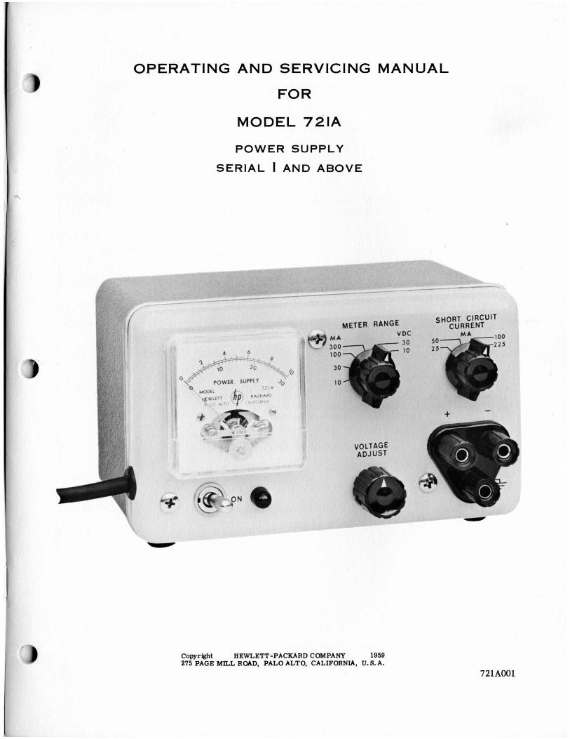
0,PERATING AND SERVICING MANUAL
FOR
MODEL 721A
P O W E R SUPPLY
SERIAL 1 AND ABOVE
Copyright HEWLETT-PACKARD COMPANY 1959 275 PAGE MILL ROAD, P A L 0 ALTO, CALIFORNIA, U. S. A.
721A001

Model 721A
SPECIFICATIONS
REGULATEDOUTPUT VOLTAGE:
FULL LOAD OUTPUT CURRENT:
LOAD REGULATION:
RIPPLE AND NOISE:
OUTPUT IMPEDANCE:
METER RANGES:
OVERLOAD PROTECTION:
OUTPUT TERMINALS:
POWER:
WEIGHT
DIMENSIONS:
0 to 30 volts dc, continuously variable.
150 ma.
With the me te r monitoring voltage, the changein output voltage from nc load to full load is less than 0.3% or 30 mv whichever is greater a1 any output.
Less than 150 pv rms.
Less than 0.2 ohm in series with less than 30 ph, output terminal€ shunted by 0.1 pf.
Full scale indications of: l o m a , 30 ma, 100 ma, 300 ma, 10 v and 30 v
Maximum current selected by switch in four steps, 25 ma, 50 mal 100 m a and 225 ma.
Three banana jacks spaced 3/4 in. apart. Positive and negative termin- als are isolated from chassis. A maximum of 400 volts may be con- nected between ground and either output terminal.
115/230 volts *lo%, 50-60 cps, 16 watts.
Net 4 lbs., shipping 7 lbs.
7 in. wide, 4-3/8 in. high, 5-1/4 in. deep.

Model 721A
CONTENTS
SECTION I GENERAL INFORMATION Page
1 . 1 Manual Content . . . . . . . . . . . . . . . . . . . . . . . . . . . . i . 1 1 . 2 General Description . . . . . . . . . . . . . . . . . . . . . . . . . i . 1 1 - 3 Inspection . . . . . . . . . . . . . . . . . . . . . . . . . . . . . . . 1 - 1 1 - 4 P o w e r c a b l e . . . . . . . . . . . . . . . . . . . . . . . . . . . . . 1 - 1 1 . 5 230 Volt Operation . . . . . . . . . . . . . . . . . . . . . . . . . . 1 . 2
SECTION I1 OPERATING INSTRUCTIONS
2 . 1 Operating Controls . . . . . . . . . . . . . . . . . . . . . . . . . . I1 . 1 2 . 2 Meter Range Switch . . . . . . . . . . . . . . . . . . . . . . . . . I1 . 1
Short Circuit Current Switch . . . . . . . . . . . . . . . . . . . . . Series Operation of Supplies . . . . . . . . . . . . . . . . . . . . . Parallel Operation of Supplies . . . . . . . . . . . . . . . . . . . .
2 . 3 2 . 4 2 . 5
I1 . 1 I1 . 1 I1 . 3
SECTION I11 THEORY OF OPERATION
3 . 1 General Circuit Description . . . . . . . . . . . . . . . . . . . . . 111 . 1 Main and Auxiliary Supply Description . . . . . . . . . . . . . . . .
3 . 3 Reference Voltage . . . . . . . . . . . . . . . . . . . . . . . . . . I11 . 1 3 . 4 Regulation Cycle Description . . . . . . . . . . . . . . . . . . . . I11 . 1 3 . 5 Short Circuit Curren t Limiting Circuit . . . . . . . . . . . . . . . I11 . 1
Output Surge Protection Circuit . . . . . . . . . . . . . . . . . . . 3 . 7 Frequency Response Control . . . . . . . . . . . . . . . . . . . . . 111 . 2
3 . 2 I11 . 1
3 . 6 111 . 2
SECTION IV MAINTENANCE
4 - 1 4 - 2 4 - 3 4 - 4 4 - 5 4 - 6 4 - 7 4 - 8 4 - 9 4 . 10
Contents . . . . . . . . . . . . . . . . . . . . . . . . . . . . . . . IV . 1 General Maintenance Information . . . . . . . . . . . . . . . . . . . IV 01 Trouble Localization . . . . . . . . . . . . . . . . . . . . . . . . . IV . 1 Checking Voltage Regulation and Ripple . . . . . . . . . . . . . . . . IV . 3 Measuring AC Internal Impedance . . . . . . . . . . . . . . . . . . IV . 3 Meter Calibration . . . . . . . . . . . . . . . . . . . . . . . . . . . . IV . 3 Setting Maximum Output Voltage . . . . . . . . . . . . . . . . . . . IV . 5 Calibrating the Short Circuit Current Circuit\ . . . . . . . . . . . . IV . 5 Replacing the Power Transis tor . . . . . . . . . . . . . . . . . . . IV . 5 Replacing Diodes CR5, CR6 and CR7 . . . . . . . . . . . . . . . . . IV . 5
SECTION V TABLEOFREPLACEABLEPARTS
5 . 1 Table of Replaceable Parts . . . . . . . . . . . . . . . . . . . . .

Model 721A Sect. I Page 1
1-1 M A N U A L CONTENT
T h e material for this instruction manual is written in five sections:
Section I contains mater ia l of a general nature.
Section I1 explains how to operate the power supply.
Section I11 explains how the circuit operates.
Section IV covers maintenance and trouble shooting procedures.
Section V is a table of replaceable parts.
1-2 GENERAL DESCRIPTION
The @Model 721A Power Supply produces a dc regulated voltage adjustable f rom 0 to 30 volts. The supply makes load circuit performance inde- pendent of external power supply influences. The supply has very low source impedance and ex- cellent regulation against change in l ine and/or load.
This supply is especially useful as a source of power for t ransis tor circuits. A circuit is provided which electronically l imits the maximum output cur- rent that can be supplied to four nominal values selected by a front panel switch. This feature helps prevent the accidental destruction of a n expensive t ransis tor should an accident occur that would nor- mally allow excessive current to flow through it. The SHORT CIRCUIT CURRENT switch can be set to the value which is closest above the normal operating current. The supply will automatically l imit the peak current flow to this nominal value regardless of the load resistance.
Built-In Metering
A built-in meter allows either output voltage or current to be monitored as selected by theMETER RANGE switch.
SECTION I GENERAL INFORMATION
Isolated Output
The power supply has both output terminals in- sulated from chassis ground. Either terminal may be grounded or a number of supplies may be con- nected in series to obtain higher voltages. Insula- tion is such that the supply may be operated as high as 400 volts off of ground.
Parallel ODeration
Parallel operation of two or m o r e supplies is pos- s ible due to the unique electronic current limiting switch. The supplies will each contribute only the number of mill iamperes selected by the SHORT CIRCUIT CURRENT switch. The individual supplies may be loaded to approximately 225 ma with some reduction in ripple and regulation characterist ics.
Reliability
The Model 721A Power Supply is very compact, and has low internal losses., which are made possible by fully transistorized circuitry. The trouble free character is t ics of t ransis tors together with the use of high quality components throughout, will resul t in a minimum of maintenance.
1-3 INSPECTION
When the Model 721A is received, inspect it for damage received in transit . Operate the instrument to make certain that it is functioning satisfactorily. If damage is evident, follow the procedures outlined in the “CLAIM FOR DAMAGE IN SHIPMENT” page of this manual.
1-4 P O W E R CABLE
The power cable consists of three conductors and is terminated in a three-prong male connector rec- ommended by the National Electrical Manufac-

Sect. I Page 2 Model 721A
turers' Association. The third contact is an offset round pin added to a standard two-blade connector which grounds the instrument chassis when used with an appropriate receptacle. To use thisNEMA connector in a two-contact receptacle, a three- prong to two-prong adapter should be used. When the adapter is used, the third contact is terminated in a short lead f rom the adapter which can be con- nected to the outlet mounting box in o rde r to ground the instrument cabinet.
1-5 230 VOLT OPERATION
This instrument may be easily converted f rom 115 to 230 volt operation by removing two jumpers and installing one jumper. This changes the dual 115 volt p r imary windings from a parallel to a series connection. Refer to the schematic diagram and Figure 4-6 for details. The main fuse should be changed from 1/4 ampere slow-blow type to 1/8 ampere slow-blow type.
'I
Model 721A Sect. I1 Page 1
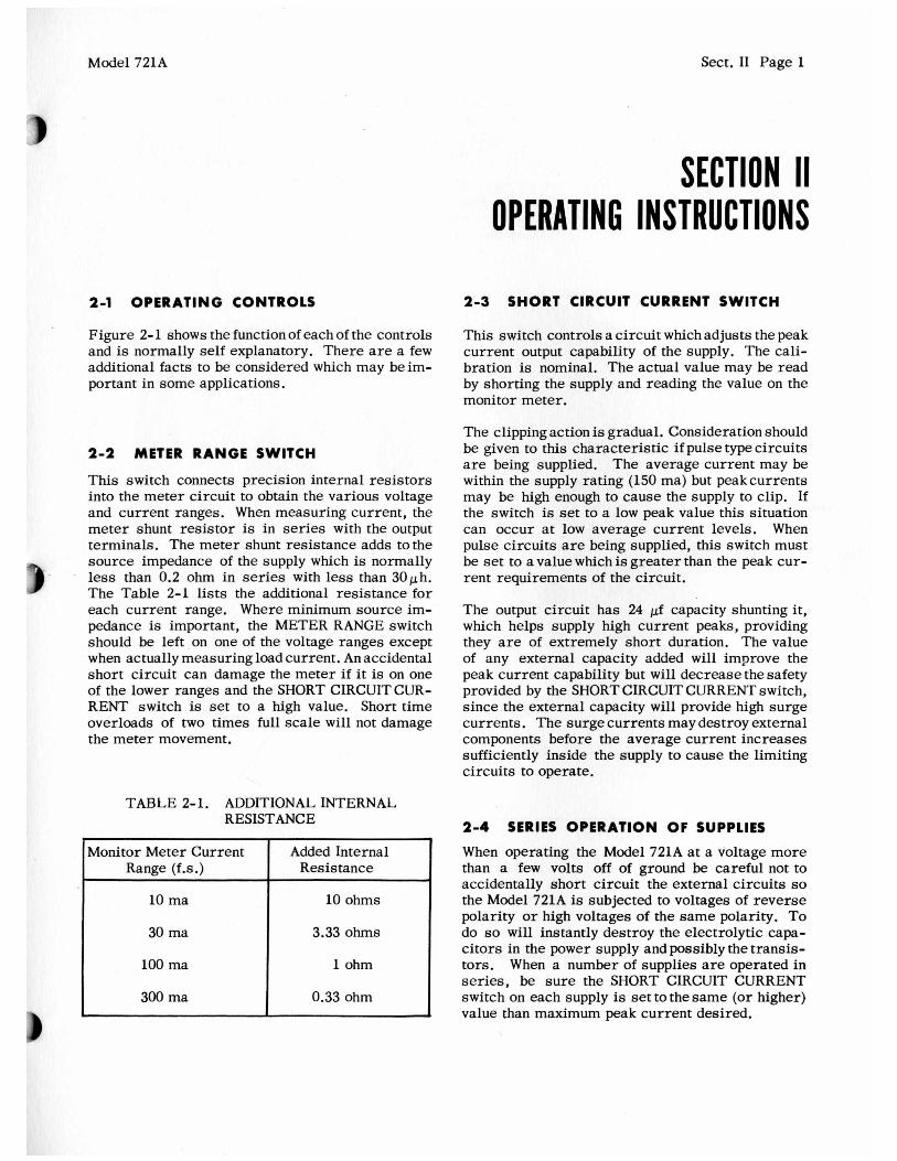
2-1 OPERATING CONTROLS
Figure 2- 1 shows the function of each of the controls and is normally self explanatory. There are a few additional facts to be considered which may beim- portant in some applications.
2-2 METER R A N G E SWITCH
This switch connects precision internal resistors into the meter circuit to obtain the various voltage and current ranges. When measuring current , the meter shunt resistor is in series with the output terminals. The meter shunt resistance adds to the source impedance of the supply which is normally less than 0.2 ohm in series with less than 30ph. The Table 2-1 lists the additional res is tance for each current range. Where minimum source im- pedance is important, the METER RANGE switch should be left on one of the voltage ranges except when actually measuring load current. An accidental shor t circuit can damage the meter if it is on one of the lower ranges and the SHORT CIRCUIT CUR- RENT switch is set to a high value. Short t ime overloads of two times full scale will not damage the meter movement.
SECTION II OP ERATlN G INSTRUCT10 NS
2-3 SHORT CIRCUIT CURRENT SWITCH
This switch controls a circuit which adjusts the peak current output capability of the supply. The C a l i - bration is nominal. The actual value may be read by shorting the supply and reading the value on the monitor meter.
The clipping action is gradual. Consideration should be given to this character is t ic if pulse type circuits are being supplied. The average current may be within the supply rating (150 ma) but peakcurrents may be high enough to cause the supply to clip. If the switch is set to a low peak value this situation can occur at low average current levels. When pulse circuits are being supplied, this switch must be set to a value which is grea te r than the peak cur- rent requirements of the circuit.
The output circuit has 24 pf capacity shunting it, which helps supply high current peaks, providing they are of extremely shor t duration. The value of any external capacity added will improve the peak current capability but will decrease the safety provided by the SHORT CIRCUIT CURRENT switch, s ince the external capacity will provide high surge currents. The surge currents may destroy external components before the average current increases sufficiently inside the s u i l y to cause the limiting circuits to operate.
TABLE 2- 1. ADDITIONAL INTERNAL
2-4 SERIES OPERATION O F SUPPLIES RESISTANCE
I Monitor Meter Current I Added Internal Range (f.s.) Resistance
10 m a 10 ohms
I 3-33 Ohms I 30 ma
100 ma I 1 ohm
300 m a 0.33 ohm I I
When operating the Model 721A at a voltage m o r e than a few volts off of ground be careful not to accidentally short circuit the external circuits so the Model 721A is subjected to voltages of r e v e r s e polarity or high voltages of the s a m e polarity. To do so will instantly destroy the electrolytic capa- citors in the power supply and possibly the transis- tors. When a number of supplies are operated in series, be s u r e the SHORT CIRCUIT CURRENT switch on each supply is set to the s a m e (or higher) value than maximum peak current desired.

Sect. I1 Page 2 Model 721A
METER READS OUTPUT SELECT METER FUNC- SELECT MAXIMUM VOLTS OR CURRENT AS TION AND RANGE CURRENTOUTPUT
Note: Meter shunt resistance is in series with load on ma. Leave on volts for lowest (rated) internal impedance.
SELECTED BY METER RANGE SWITCH I
I
/ POWER ON/OFF ADJUST OUTPUT VOLT-
AGE OR CURRENT Output increases with clockwise
rota tion
CAUTION
DO NOT SUBJECT POWER SUPPLY OUTPUT TERMINALS TO A VOLTAGE SOURCE OF REVERSE POLARITY. TO DO SO WILL DE- STROY A TANTALUM CAPACITOR CONNEC- TED ACROSS THESE TERMINALS
Figure 2-1. Model 721A Power Supply
CONNECT LOAD TO (+) AND (0) TERMINALS
Either terminal may be connected to grounded cabinet terminal. (+) and (-) terminals may be operated up to k400 volts dc from cabinet ground
M P - S - 445
0 pera ti ng Controls
.
Model 721A Sect.II Page 3
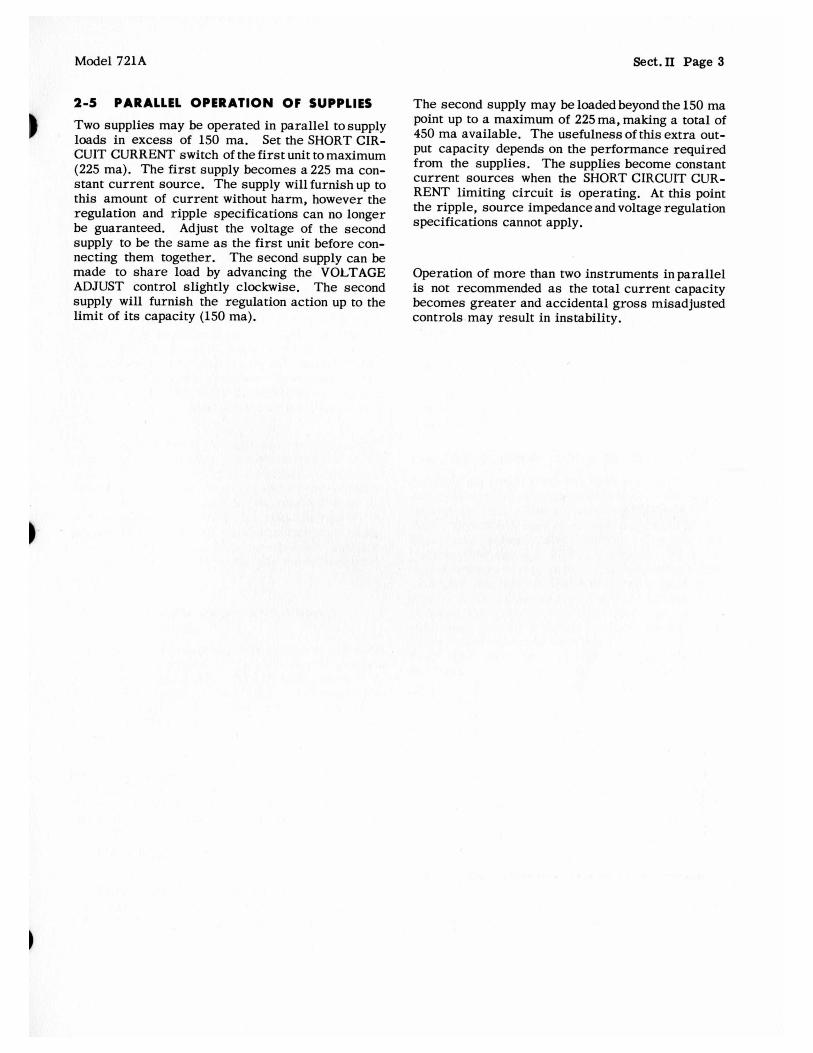
2-5 PARALLEL OPERATION OF SUPPLIES The second supply may be loaded beyond the 150 m a Two supplies may be operated in parallel tosupply loads in excess of 150 ma. Set the SHORT CIR- CUIT CURRENT switch of the f i r s t unit to maximum (225 ma). The first supply becomes a 225 m a con- stant current source. The supply will furnish up to this amount of current without harm, however the regulation and ripple specifications can no longer be guaranteed. Adjust the voltage of the second
point up to a maximum of 225 ma, making a total of 450 m a available. The usefulness of this extra out- put capacity depends on the performance required from the supplies. T h e supplies become constant current sources when the SHORT CIRCUIT CUR- RENT limiting circuit is operating. At this point the ripple, source impedance and voltage regulation specifications cannot apply.
supply to be the s a m e as the f i r s t unit before con- necting them together. The second supply can be made to s h a r e load by advancing the VOLTAGE ADJUST control slightly clockwise. T h e second supply will furnish the regulation action up to the l imit of its capacity (150 ma).
Operation of m o r e than two instruments inparal le l is not recommended as the total current capacity becomes greater and accidental gross misadjusted controls may resul t in instability.

Model 721A Sect. 111 Page 1
SECTION Ill
3-1 GENERAL CIRCUIT DESCRIPTION
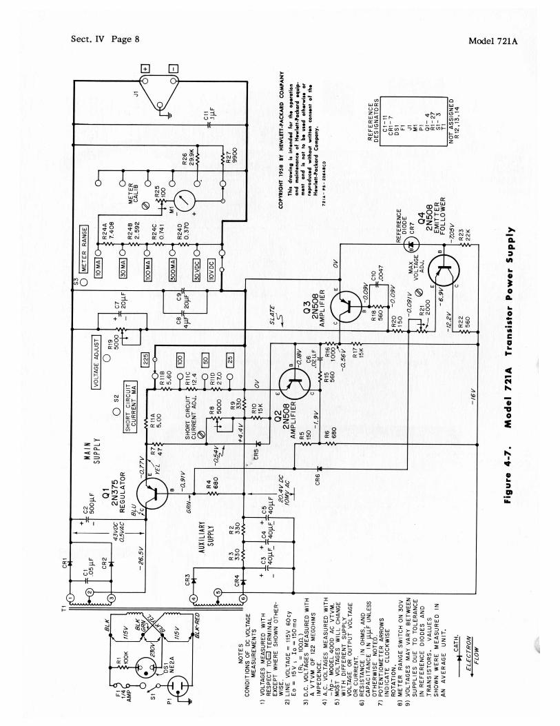
The regulation is accomplished in a manner which is s imi la r to vacuum tube type circuits. Apower type transis tor in series with the rectified output and the load, acts like a variable resistor which maintains a constant output voltage or current as selected by the controls. The power t ransis tor is controlled by a two stage amplifier which amplifies any changes in the relative amplitudes of the output voltage and the reference voltage.
The electronic shor t circuit current limiting switch is a unique feature which is not normally found in the vacuum tube counterpart of the supply. This circuit senses any increase in current above a pre-selected value and in turn controls the conduction of the power t ransis tor to limit the peak current to the pre-selected value. A detailed description of the Power Supply and its operation follows. Refer to the schematic diagram to identify the various com- ponents.
3-2 M A I N A N D A U X I L I A R Y SUPPLY DESCRIPTION
Transformer T1 supplies ac voltages to the main and auxiliary supplies. The main supply consists of silicon rectifiers CR1 and CR2 and capacitor C2. This supply furnishes about 43 volts to the regulator circuit. Silicon rectifier CR3, CR4 and capacitors C3, C4 and C5 supply -20 volts, which is required f o r operation of the control circuits. Regulator t ransis tor Q1 acts as a variable series resis tance to lower the voltage to the desired value, as set by the front panel VOLTAGE ADJUST control R19. Q1 conducts m o r e current when the base volt- age goes more negative with respect to the emitter.
3-3 REFERENCE VOLTAGE
CR7 is a reversed biased diode operating in the break-down condition. The diode maintains a con- s tant nominal 7 volts across itself, establishing a constant reference voltage between the negative out-
1
THEORY OF OPERATION
put lead and the base of 44. 4 4 is a n emit ter follower which repeats the reference voltage at its emit ter terminal, less a constant internal base- emit ter drop of about 0.2 volt. The voltage at the emit ter has a low source impedance, making it insensitive to normal variations in current flow. The output voltage from the (+) output bus is sampled by VOLTAGE ADJUST control R19 which causes a current flow through R20 and R21. The regulator action maintains a constant current through R19 and R20.
3-4 REGULATION CYCLE DESCRIPTION
Assume the output level has been set with R19 and some change has occurred which causes the output voltage to rise. The voltage at the base of 43 is that which would appear across a forward biased diode and is essentially constant. The electron current flow through R20 is constant. When the output voltage rises, par t of the normal electron flow into the base of 43 is diverted through R19. The reduced base-emitter electron current of 43 reduces the collector-emitter electron current flow f rom R17 by a factor of approximately 100. Since fewer electrons flow into the collector of 4 3 f rom R17 and the - 16 volt bus, the voltage at R16 goes in a negative direction. This causes more electrons to flow through R16 into the base of 42. Increased 4 2 base to emit ter current causes much higher collector-emitter current. Increased 4 2 collector current raises the voltage at R5 which reduces the base to emi t te r current of Q1. The reduced base-emitter cur ren t of Q1 increases its collector-emitter res is tance to electron current flow, hence increases its collector to emitter volt- age drop. That voltage drop increases just enough to compensate for the initial output voltage rise, maintaining the output voltage at a constant level.
3-5 SHORT CIRCUIT CURRENT L I M I T I N G CIRCUIT
The current flow to the load is sensed by a voltage drop across R11 ABCD. Silicon diode CR5 is

Sect. I11 Page 2 Model 721A
forward biased approximately 0.4 volt which is not enough voltage to cause appreciable cur ren t flow. Screwdriver adjust control R8 adjusts the value of the forward bias slightly to calibrate the circuit. The voltage at the junction of R7 andR8 goes more negative as the load cur ren t increases, which also lowers the voltage at the base of 42 . 4 2 conducts m o r e current which raises the base voltage of Q1 maintaining the load current at the pre-selected value. The SHORT CIRCUIT CURRENT switch selects the value of resis tance which will give the correct value of sensing voltage to cause the circuit to operate at the load cur ren t selected.
3-6 OUTPUT SURGE PROTECTION CIRCUIT
Diode CR6 prevents a large surge output when the output VOLTAGE ADJUST control R19 is set to a low value (nearly full counterclockwise) and the power switch is turned off. This would normally occur because the auxiliary supply voltage decays fas te r than the main supply due to the large storage capacity of C2. When the auxiliary supply stops, the base voltage of Q1 would not be controlled. Q1
would then conduct very heavily. The resulting output su rge could damage external components. CR6 connects the base of Q l to the junction of R20 and R21. This point is normally about -0.9 volt. When the supply is turned off, 44 stops conducting and this point rises towards + 40 volts because of the low resis tance path provided by R19. CR6 is then forward biased and pulls the base of Q1 positive which cuts Q1 off, preventing any output surge.
3-7 FREQUENCY RESPONSE C O N T R O L
C10 bypasses R18 fo r high frequencies, which raises gain of 4 3 . C6 and R15 provide negative feedback around 4 2 to improve the frequency response.
C7 bypasses R19 to provide a constant maximumac feedback from the dc output to the control c i rcui t amplifier regardless of the setting of R19. C8 by- passes C9 to compensate for increased effective series resis tance in C9 at temperatures below OOC. C11 provides low internal impedance at high frequencies. C1 is an r f bypass to eliminate noise introduced by the power line.
Sect. N Page 0 Model 721A
1.
3.
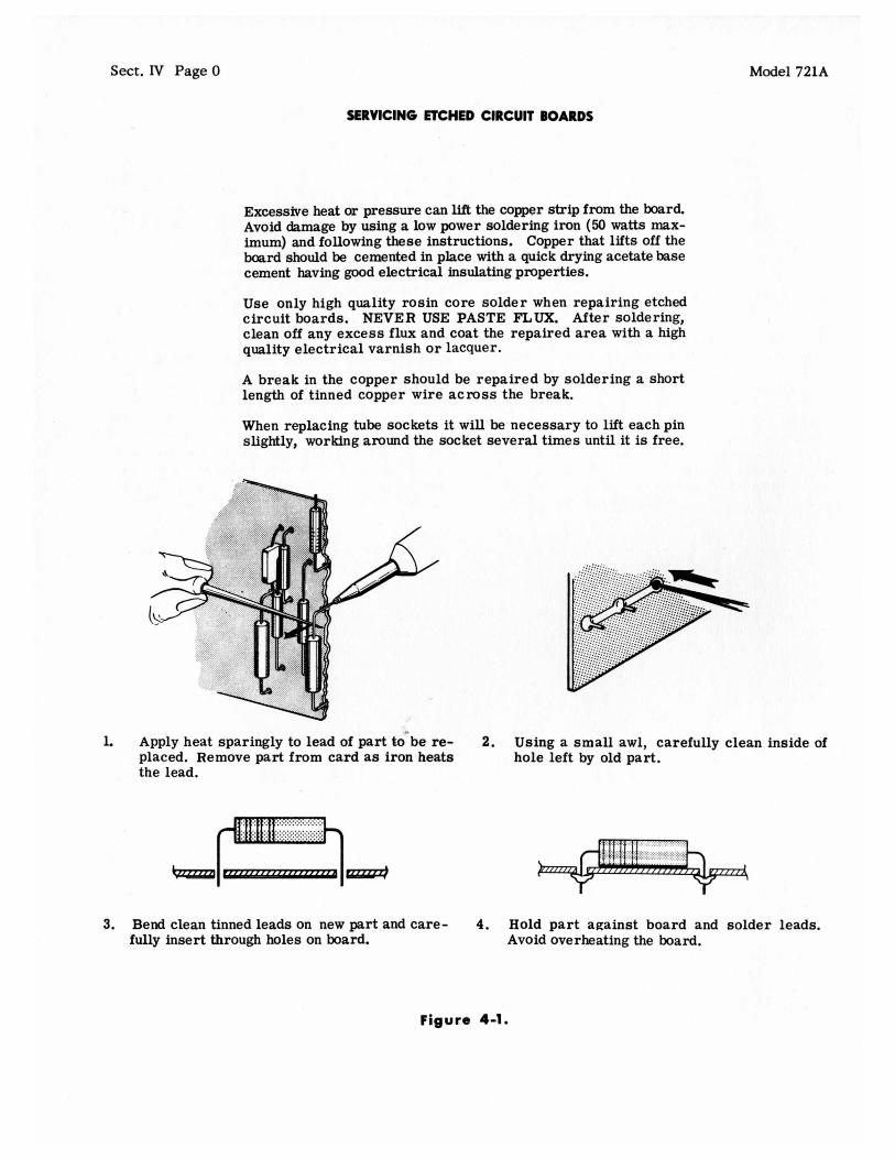
SERVICING ETCHED CIRCUIT BOARDS
Excessive heat or pressure can lift the copper strip from the board. Avoid damage by using a low power soldering iron (50 watts max- imum) and following these instructions. Copper that lifts off the board should be cemented in place with a quick drying acetate base cement having good electrical insulating properties.
Use only high quality rosin core solder when repairing etched circuit boards. NEVER USE PASTE FLUX. After soldering, clean off any excess flux and coat the repaired area with a high quality electrical varnish or lacquer.
A break in the copper should be repaired by soldering a short length of tinned copper wire across the break.
When replacing tube sockets it will be necessary to lift each pin slightly, working around the socket several times until it is free.
Apply heat sparingly to lead of part t k b e re- placed. Remove part from card a s iron heats the lead.
-1-1- Bend clean tinned leads on new part and care- fully insert through holes on board.
2.
4.
Using a small awl, carefully clean inside of hole left by old part.
Hold part against board and solder leads. Avoid overheating the board.
Fiaure 4-1.
Model 721A Sect. IV Page 1
SECTION IV MAINTENANCE
4-1 CONTENTS
This section tells how to make internal adjustments, locate trouble and how to check over-all perform- ance. Paragraphs 4-4 and 4-5 may be used as a rapid performance check to certify that the power supply is operating within published specifications. These tests can be made with the instrument in its cabinet.
4-2 GENERAL MAINTWANCE INFORMATION
The power supply has no par ts which have a definite limited life. The instrument should operate indefi- nitely with no routine maintenance. If any par ts are replaced you should recheck the settings of the screwdriver controls which set the maximum output voltage (R21) and maximum short circuit current (R8). Variations among par ts may make it neces- s a r y to readjust these controls slightly. Reseal the control with duco cement after adjustment, otherwise the setting will change with shock and vi bra tion.
1
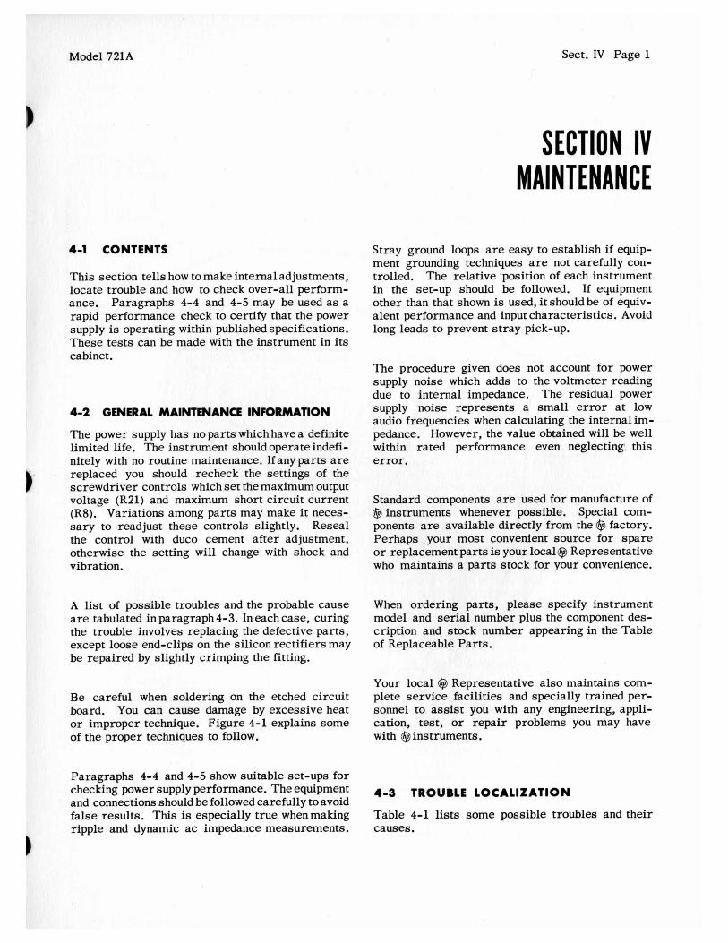
Stray ground loops are easy to establish if equip- ment grounding techniques are not carefully con- trolled. The relative .position of each instrument in the set-up should be followed. If equipment other than that shown is used, it should be of equiv- alent performance and input characterist ics. Avoid long leads to prevent s t r a y pick-up.
The procedure given does not account for power supply noise which adds to the voltmeter reading due to internal impedance. The residual power supply noise represents a small error at low audio frequencies when calculating the internal im- pedance. However, the value obtained will be well within rated performance even neglecting: this error.
Standard components are used for manufacture of @ instruments whenever possible. Special com- ponents are available directly f rom the @ factory. Perhaps your most convenient source for spare or replacement par ts is your local@ Representative who maintains a par t s stock for your convenience.
A list of possible troubles and the probable cause When ordering parts, please specify instrument are tabulated in paragraph 4-3. In each case, curing model and serial number plus the component des- the trouble involves replacing the defective parts, cription and stock number appearing in the Table except loose end-clips on the silicon rectifiers may of Replaceable Parts. be repaired by slightly crimping the fitting.
Your local @ Representative also maintains com- Be careful when soldering on the etched circuit plete se rv ice facilities and specially trained per- board. You can cause damage by excessive heat sonnel to assist you with any engineering, appli- or improper technique. Figure 4-1 explains some cation, test, or repair problems you may have of the proper techniques to follow. with @instruments.
Paragraphs 4-4 and 4-5 show suitable set-ups for checking power supply performance. The equipment 4-3 TROUBLE LOCAL~ZAT~ON and connections should be followed carefully to avoid false results. This is especially t rue whenmaking ripple and dynamic ac impedance measurements.
Table 4-1 lists some possible troubles and their causes.
1
Sect. IV Page 2
V A R I A B L E VOLTAGE TRANSFORMER
Model 721A
@ M O D E L 4000 READ NOISE
ADJUST 0 BUCKING "OL TAG E
Figure 4-2. Checking Voltage Regulation and Ripple

A' 721A Sect. IV Page 3
'ABLE 4-1. TROUBLE LOCALIZATION CHART
I Trouble Symptom
Output voltage unstable Poor regulation Wandering voltage
Poor regulation (line or load)
High noise or ripple on dc output (ap- proximately 30 mv 50 to 150 kc)
Microphonics
Voltage control not smooth
Probable Cause
Defective reference diode CR7.
Poor contact at end clips on CR1, CR2, CR3 or CR4.
Defective Q1, 42, 4 3 449
Open C6 or possibly c10.
Noisy R19.
Defective R19.
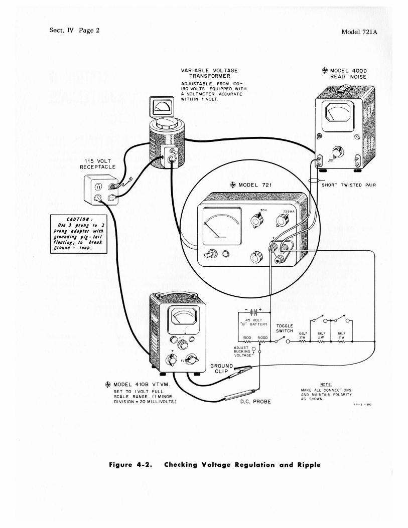
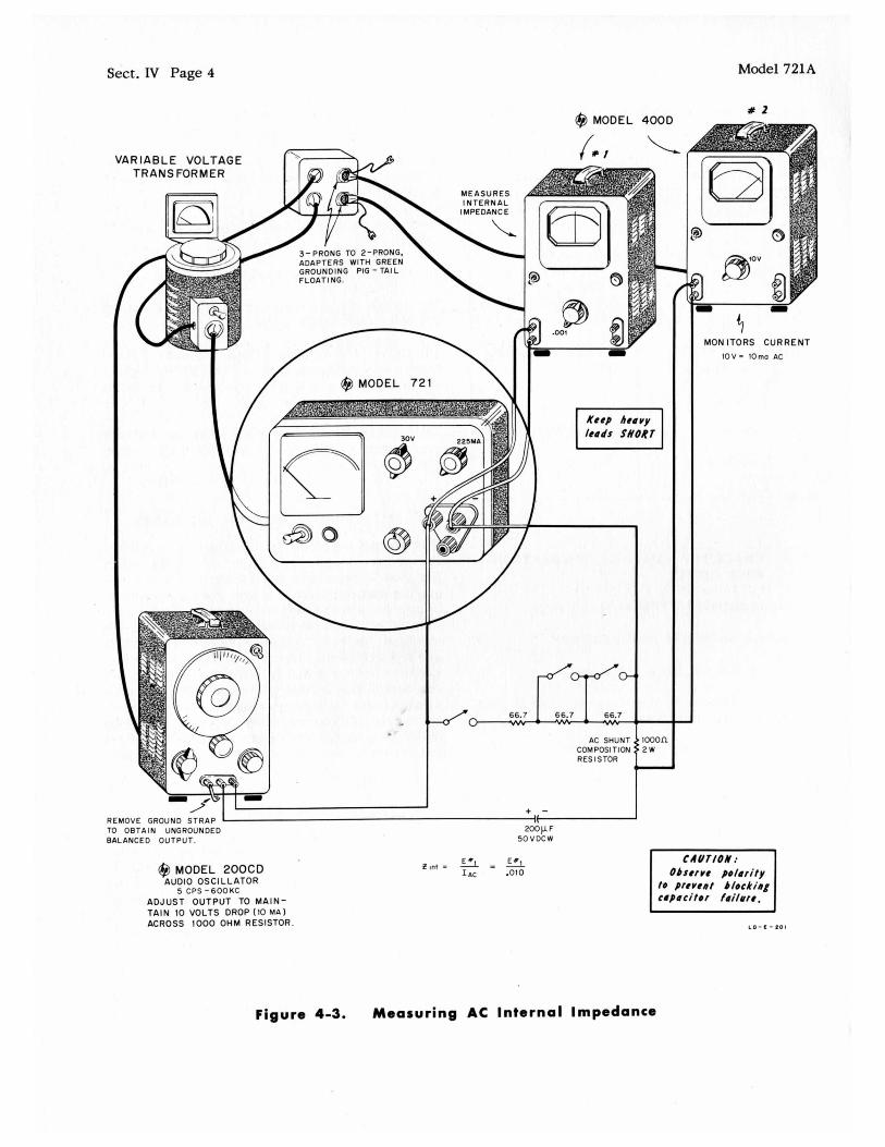
4-5 MEASURING AC INTERNAL IMPEDANCE
4-4 CHECKING VOLTAGE REGULATION A N D RIPPLE
1) Set Model 410B VTVM to 30 volt range. 1
2) Adjust Model 721A to 30 volt output.
3) Adjust line voltage to 115 volts.
4) Adjust Battery-Potentiometer to obtain 30 volts. VTVM will then read 0 volt.
5) Switch VTVM to 1 volt range.
6) Adjust bucking voltage so VTVM pointer sits at about 1/2 scale.
7) Switch from full load to no load. Load = 200 ohms.
8) Voltage will not change more than 0.3% (0.09 v) at 30 volts output, which is worst condition.
9) Repeat at 20 volts and 10 volts if desired. (Short out one or two 66.7 ohm resistors to get 150 ma rated load, depending on voltage selected). Readjust bucking voltage so VTVM is again at mid-scale.
1
20 v x .003 = 60 mv maximum change 10 v x .003= 30 mv maximum change
At voltages less than 10 volts, change fromno load to full load will result in less than 30 mv change in voltage.
10) Repeat test with l ine voltage at 103 and 127 volts.
11) Adjust line voltage to 115 volts.
12) Adjust output voltage to 30 volts and load to 200 ohms (for rated current). . 13) Change line voltage t l O % to 103 and 127 volts. Output will change less than .3% (.09 v). This is worst condition. At outputs below 5 v dc, regulation is within *15 mv.
14) Measure ripple with Model 400D, use 1 mv full scale range. Ripple + noise will be less than 15Opv (0.15 mv).
The internal impedance of the supply is affectedby the ac gain of the regulator circuit. If the supply has good dc regulation and low ripple ac in the out- put the supply should also have low ac impedance. Figure 4-3 shows a suitable set-up for checking the internal ac impedance if desired. The set-up shown should be followed faithfully if meaningful results are to be obtained. The level of signal to be mea- sured is very low and ground loops in the system can easily give very large errors. The measure- ment is made by driving a constant 10ma alternat- ing current through the power supply and measuring the IZ drop across the output terminals. The inter- nal impedance can be easily calculated by ohm's law.
4-6 METER CALIBRATION
The meter mechanical zero should be accurately set before calibration. The correct way to do this is to rotate the adjust screw clockwise until the pointer swings up scale and then starts to swing down scale toward zero. Continue rotating the ad- just screw clockwise until the pointer is exactly over zero. If you overshoot, continue turning the screw clockwise until the pointer is again approach= ing zero from the up scale side.
The internal meter is calibrated by connecting an external standard milliammeter across the output
Sect. IV Page 4 Model 721A
@MODEL 4000
66.7 - AC SHUNT
COM POSl TI ON RES ISTOR
I I
TO OBTAIN UNGROUNDED 200p F BALANCED OUTPUT. SOVDCW
+ - REMOVE GROUND STRAP i-
@MODEL 200CD AUDIO OSCILLATOR
5 CPS - 6 0 0 K C ADJUST OUTPUT TO M A I N - TAIN 10 VOLTS DROP (10 MA ) ACROSS 1000 OHM RESISTOR.
t i n t = E*1 I AC
- E *l .010
- tooon 2 w -
a 2
MON ITORS C U R R E N T
1OV= lOmo AC
cmr /oA .- Observe p d a r i t y
to prevent blocking capacitor fai/ure.
L O - L - L O I
Figure 4-3. Measuring AC Internal Impedance

Model 721A Sect. IV Page 5
*erminals in series with approximately 1,000 ohms. The output VOLTAGE ADJUST control should be idvanced until the standard me te r indicates 10 ma. rhe internal me te r should be switched to the 10 ma range. Adjust R25 until the internal me te r reads *he same as the external meter. All other current ind voltage calibrations wi l l then be determined by :he precision current and voltage multiplier re&- :or8 associated with the METER RANGE switch.
1-7 SETTING M A X I M U M OUTPUT VOLTAGE
rhe maximum output voltage should be set to be 3 1 volts.
1) Turn the VOLTAGE ADJUST control fullclock- wise.
2) Measure the output voltage with either internal voltmeter or an external standard voltmeter.
3) Adjust R21 to obtain 31 volts.
4) Reseal the control with duco cement.
4) Adjust R8 to obtain 230 ma.
NOTE
This adjustment provides the best over-all cali- bration of this circuit on all ranges. The circuit is slightly temperature sensitive. With the instru- ment in its cabinet and hot, the maximum current available will be approximately 225 ma. --------- 5) Reseal the control with duco cement.
4-9 REPLACING THE POWER TRANSISTOR
If you replace the power t ransis tor (Ql) be careful to note how the nylon bushings are installed in the transistor mounting holes. They must be reinstalled properly since the case of the t ransis tor is not at chassis potential. You should also check that there are no bu r r s on the t ransis tor case which can cut through the anodized surface of the mounting plate. The anodized surface acts as a good electrical in- sulator while allowing good heat transfer from the transistor. If this surface is damaged the maximum voltage at which the power supply can be operated off of ground potential may be reduced.
4-10 REPLACING DIOD6 CR5, CR6 AND CR7 4-8 CALIBRATING THE SHORT CIRCUIT CURRENT CIRCUIT
The diodes CR5, CR6 and CR7 are manufactured by @. They have carefully controlled character- istics which result in a superior performing instru- ment. Should replacement be necessary we rec- ommend that you use s imi l a r diodes. You may obtain these from your local @Representative or by ordering directly from the factory. The cathode end of the diode is marked with aspot of red paint.
1) Rotate the SHORT CIRCUIT CURRENT switch to 225 ma.
2) Short circuit the output terminals.
3) Rotate the VOLTAGE ADJUST control full clock- wise.

Sect. IV Page 6
W (3 4.
E O v > f4
- b
Model 721A
M -0
CD 0
c U 0
s 0) .I > I
0 E
0)
E
L
c
I
E
m
4 F4 h
0) 'II 0
0
0 c c
I
Sect. IV Page 7 ! lA
RANGE
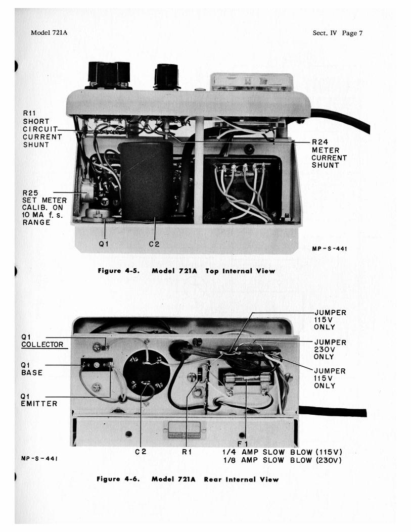
1 Figure 4-5. Model 7 2 1 A
-R24 METER CURRENT SHUNT
MP-S -441
Top Internal View
1 1 5 V ONLY
-
Qi - EMITTER
S - 4 4 1
I JUMPER
Q 1 2’ -_ I
CO L LECTOR
Qi BASE
T_
.?..-+.*--.- - x.&. .. B JUMPER
230V ONLY
~ J U M P E R 1 1 5 V ONLY
d 1
c 2 R I 1/4 AMP SLOW BLOW (115V) 1/8 AMP SLOW BLOW (230V)
Figure 4-6. Model 7 2 1 A Rear Internal View
Sect. IV Page 8 Model 721A
c c
3-1 V-
I 1 I o I - 1 I
% e e 3 v)
I
L
r" 0 P
0 L
c H
H .I
C
c

Sect.V Page 1
SECTION V TABLE OF REPLACEABLE PARTS
N O T E
A n y c h a n g e s i n t h e T a b l e o f R e p l a c e a b l e P a r t s w i l l b e
l i s t e d o n a P r o d u c t i o n C h a n g e s h e e t at t h e f r o n t o f t h i s
m a n u a l .
W h e n o r d e r i n g p a r t s f r o m t h e f a c t o r y a l w a y s i n c l u d e
t h e f o l l o w i n g i n f o r m a t i o n : D I
I n s t r u m e n t M o d e l N u m b e r
S e r i a l N u m b e r
@ S t o c k N u m b e r o f P a r t
D e s c r i p t i o n o f P a r t

Sect. V Page 2
T A B L E O F R E P L A C E A B L E P A R T S
Model 721A
CIRCUIT REF.
c1
c 2
c3,4, 5
C6
c 7
C 8
c 9
c10
Cl l
CR1,' 2, 3, 4
ZR5,6
ZR7
IS1
?1
ri
ull
?1
21
22,3,4
DESCRIPTION, MFR. * 8z MFR. DESIGNATION
Capacitor: fixed, ceramic, . 0 5 pf *20%, 400 VdCW
500 pf, 75 VdCW cc*
40 pf -15% +loo%, 50 VdCW
NN*
Capacitor: fixed, electrolytic,
Capacitor: fixed, electrolytic, cc *
Capacitor: fixed, mylar, .02 pf *20%, 400 vdcw Texas Capacitor Co
Capacitor: fixed, electroyltic, 20 pf -15% + loo%, 50 vdcw CC"
Capacitor: fixed, electrolytic, 4 pf - 15% + 20%, 60 VdCw AH*
Same as C7
Capacitor: f ixed, mylar, .0047 pf *lo%, 400 vdcw
0.1 yf &5%, 200 vdcw
type 10M AA*
CW'
Capacitor: fixed, mylar, CW'
Rectifier, silicon:
Diode HP*
Diode, breakdown HP*
Light, indicator: 1/25 W, NE2 Eldema
Fuse, cartridge: 0.25 amp, .- 12 5 V, "~10 - blo" E*
Zonsists of: Binding post, black HP* Binding post, red HP* Insulator, binding post, dual HP* Insulator, binding post, triple HP*
Meter HP*
Zord, power Cornish Wire Co.
hans is tor : 2N375 zz*
rransistor: 2N508 Z Z *
See "Lis t of Manufacturers Code Letters F o r Replaceable Pa # Total quantity used in the instrument.
@ STOCE NO.
15-161
18-68HP
18-71
16-113
18-70
18-15
16-105
16-103
212-134
2 - 29A -7A
2-29A-7A
45-24
ill-55
4C -lOC iC -lOD 4c-54A 4c-54c
12 -90
112-92
I13 -2N3 75
113-2N508
#
1 -
1
3
1
2
1
1
1
4
2
1
1
1
2 1 1 1
1
1
1
3
- s -Table" .

ode1 72l.A
T A B L E O F R E P L A C E A B L E P A R T S
Sect. V Page 3
CIRCUIT REF.
I1
t2, 3
14
15
16
17
18
'9
10
llABCD
12,13,14
15
16
17
18
19
20
21
22
23
DESCRIPTION, MFR. * & MFR. DESIGNATION
Resistor: fixed, composition, 100,000 ohms *lo%, 1/2 w
Resistor: f ixed, composition, 330 ohms *lo%, 1/2 W
Resistor: fixed, composition, 680 ohms *lo%, 1/2 W
Resistor: fixed, composition, 150 ohms *IO%, 1/2 W
Same as R4
Resistor: fixed, composition, 47 ohms *lo%, 1/2 w
Resistor: variable, composition, l inear taper, 5000 ohms *30%, 1/3 W
Same as R2
Resistor: fixed, composition, 15,000 ohms *lo%, 1/2 W
Res is to r : wire wound
These circui t references not assigned
Resistor: fixed, composition,
Resistor: fixed, composition, 560 ohms *lo%, 1/2 W
1000 ohms *lo%, 1/2 W
Same as R10
Same as R15
Resistor: variable, composition, l inear taper, 5000 ohms
same as R5
Resistor: variable, composition, l inear taper, 2000 ohms &30%, 1/3 W
%me as R15
Resistor: fixed, composition, 22,000 ohms *lo%, 1/2 w
B'
B'
B'
B*
B*
BO*
B"
HP*
B'
B'
G'
BO*
B'
See "List of Manufacturers Code Letters For Replaceable Pa Total quantity used in the instrument.
@ STOCK NO.
23-100K
23-330
23-680
23-150
23-47
210-134
23-15K
72lA-26A
23-560
23-1K
210-15
210-133
23-22K
ts Table" .
- #
1 -
3
2
2
1
1
2
1
3
1
1
1
1
-

Sect. V Page 4 Model 721A
CIRCUIT REF.
R24 ABCD
R25
R26
R27
Sl
52
33
ri
T A B L E OF R E P L A C E A B L E P A R T S
DESCRIPTION, MFR. * 8z MFR. DESIGNATION
Resistor: wirewound, meter range
Resistor: variable, 100 ohms
Resistor: fixed, deposited carbon, 29,900 ohms *l%, 1/2 W
Resistor: fixed, deposited carbon, 9900 ohms &l%, 1/2 W
Switch, toggle : SPST
short Circuit Switch Assembly
Switch, rotary: less components
Meter Range Switch Assembly
jwitch, rotary: less components
rransformer, power
MISCELLANEOUS
;'useholder
mob: VOLTAGE ADJUST
hob: METER RANGE, SHORT CIRCUIT CONTROL
HP'
HP'
NN'
NN'
Dd
HPd
W'
HP'
Wd
HP'
T*
€IP*
HP*
@ STOC NO.
721A-26B
M-80
33-29.9K
33-9.9K
310-11
72lA-19A
310-232
72lA-19B
310 -233
310-168
.40-17
2 - 7 0
2-74BS
See List of Manufacturers Code Letters F o r Replaceable Parts Table'(. # Total quantity used in the instrument.
#
1
1
1
-
1
1
1
1
1
1
1
1
1
2

LIST OF CODE LETTERS USED IN TABLE OF REPLACEABLE TO
A B C D E F G H HP I J K L M N 0 P Q R S T U V W X Y Z
cc DD EE FF GG HH II JJ KK LL MM NN 00 PP QQ RR SS TT uu vv ww xx YY R
AB A C A D
A H A I A J
Aerovox Corp. Allen-Bradley Co. Amperite Co. Arrow, Hart & Hegemon Bussman Manufacturing Co. Carborundum Co. Centralab Cinch-Jones Mfg. Co. Hewlett-Packard Co. Clarostat Mfg. Co. Cornell Dubilier Elec. Co. Hi-Q Division of Aerovox Erie Resistor Corp. Fed. Telephone & Radio Corp. General Electric Co. General Electric Supply Corp. Girard-Hopkins Industrial Products Co. International Resistance Co. Lectrohm Inc. Littlefuse Inc. Maguire Industries Inc. Micamold Radio Corp. Oak Manufacturing Co. P. R. Mallory Co., Inc. Radio Corp. of America Sangamo Electric Co. Sarkes Tarzian Signal Indicator Co. Sprague Electric Co. Stackpole Carbon Co. Sylvania Electric Products Co. Western Electric Co. Wilkor Products, Inc. Am phenol Dial Light Co. of America Leecraft Manufacturing Co. Switchcraft, Inc. Gremar Manufacturing Co. Carad Corp. Electra Manufacturing Co. Acro Manufacturing Co. Alliance Manufacturing Co. Arc0 Electronics, Inc.
Astron Corp. Axel Brothers Inc. Belden Manufacturing Co. Bird Electronics Corp. Barber Cqlman Co. Bud Radio Inc. Allen D. Cardwell Mfg. Co. Cinema Engineering Co. Any brand tube meeting RETM A stand a rds. Corning Glass Works Dale Products, Inc. The Drake Mfg. Co. Elco Corp. Hugh H. Eby Co. Thomas A. Edison, Inc. Fansteel Metallurgical Corp. General Ceramics & Steatite Corp. The Gudeman Co.
DESIGNATE THE MANUFACTURERS
ADDRESS
New Bedford, Mass. Milwaukee 4, Wis. New York, N. Y. Hartford, Conn. St. Louis, Mo. Niagara Falls, N. Y. Milwaukee I , Wis. Chicago 24, 111. Palo Alto, Calif. Dover, N. H. South Plainfield, N. J. Olean, N. Y. Erie 6, Pa. Clifton, N. J. Schenectady 5, N. Y. Son Francisco, Calif. Oakland, Calif. Danbury, Conn. Philadelphia 8, Pa. Chicago 20, Ill. Des Plaines, 111. Greenwich, Conn. Brooklyn 37, N. Y. Chicago IO, 111. Indianapolis, Ind. Harrison, N. J. Marion, 111. Bloomington, Ind. Brooklyn 37, N. Y. North Adorns, Mass. St. Marys, Pa. Warren, Pa. New York 5, N. Y. Cleveland, Ohio Chicago 50, 111. Brooklyn 37, N. Y. New York, N. Y. Chicago 22, 111. Wakefield., Mass. Redwood City, Calif. Kansas City, Mo. Columbus 16, Ohio Alliance, Ohio New York 13, N. Y. East Newark, N. J. Long Island City, N. Y. Chicago 44, 111. Cleveland 14, Ohio Rockford, 111. Cleveland 3, Ohio Plainville, Conn. Burbank. Calif.
Corning, N. Y. Columbus, Neb. Chicago 22, Ill. Philadelphia 24, Pa. Philadelphia 44, Pa. West Orange, N. J. North Chicago, 111. Keasbey, N. J. Sunnyvale, Ca 1 if.
CODE LETTER
AK A L A M A N A 0 AP AQ AR AS AT A U AV A W AX AY A Z BA BC BD BE BF BG BH BI BJ BK BL BM BN BO BP BQ BR BS BT BU BV BW BX BY BZ C A CB C D CE CF CG CH CI CJ C K C L CM CN co CP CQ CR cs CT cu cv cw
M A N U FACTU RE R
Hammerlund Mfg. Co., Inc. Industrial Condenser Corp. .
lnsuline Corp. of America Jennings Radio Mfg. Corp. E. F. Johnson Co. Lenz Electric Mfg. Co. M icro-Switch Mechanical Industries Prod. Co. Model Eng. & Mfg., Inc. The Muter Co. Ohmite Mfg. Co. Resistance Products Co. Radio Condenser Co. Shallcross Manufacturing Co. Solar Manufacturing Co. Sealectro Corp. Spencer Thermostat Stevens Manufacturing Co. Torrington Manufacturing Co. Vector Electronic Co. Weston Electrical Inst. Corp. Advance Electric & Relay Co. E. I. DuPont Electronics Tube Corp. Aircraft Radio Corp. Allied Control Co., Inc. Augat Brothers, Inc. Carter Radio Division CBS Hytron Radio & Electric Chicago Telephone Supply Henry L. Crowley Co., Inc. Curtiss-Wrig ht Corp. Allen B. DuMont Labs Excel Transformer Co. General Radio Co. Hughes Aircraft Co. International Rectifier Corp. James Knights Co. Mueller Electric Co. Precision Thermometer & Inst. Co. Radio Essentials Inc. Raytheon Manufacturing Co. Tung-Sol Lamp Works, Inc. Varian Associates Victory Engineering Corp. Weckesser Co. Wilco Corporation Winchester Electronics, Inc.
Mako Tool & Die Oxford Electric Corp. Camloc-Fastener Corp. George K. Garrett Union Switch & Signal Radio Receptor Automatic & Precision Mfg. co. Bassick Co. Birnbach Radio Co. Fischer Specialties Telefunken (C/O MVM, Inc.) Potter-Brumfield Co. Cannon Electric Co. Dynac, Inc. Good-All Electric Mfg. Co.
PARTS
ADDRESS.
New York 1, N. Y. Chicago 18, 111. Manchester, N. H. Son Jose, Calif. Waseca, Minn. Chicago 47, 111. Freeport, 111. Akron 8, Ohio Huntington, Ind. Chicago 5, 111. Skokie, 111. Harrisburg, Pa. Camden 3, N. J. Collingdale, Pa. Los Angeles 58, Calif. New Rochelle, N. Y. Attleboro, Mass. Mansfield, Ohio Van Nuys, Calif. Los Angeles 65, Calif. Newark 5, N. J. Burbank, Calif. Son Francisco, Calif. Philadelphia 18, -Pa. Boonton, N. J. New York 21, N. Y. Attleboro, Mass. Chicago, 111. Danvers, Mass. Elkhart, Ind. West Orange, N. J. Carlstadt, N. J. Clifton, N. J. Oakland, Calif. Cambridge 39, Mass. Culver City, Calif. El Segundo, Calif. Sandwich, 111. Cleveland, Ohio Philadelphia 30, Pa. Mt. Vernon, N. Y. Newton, Mass. Newark 4, N. J. Polo Alto, Calif. Union, N. J. Chicago 30, 111. Indianapolis, Ind. Santa Monica, Calif. Los Angeles 42, Calif. Chicago 15, 111. Paramus, N. J. Philadelphia 34, Pa. Swissvale, Pa. New York I I , N. Y. Yonkers, N. Y. Bridgeport 2, Conn. New York 13, N. Y. Cincinnati 6, Ohio New York, N. Y. Princeton, Ind. Los Angeles, Calif. Polo Alto, Calif. Ogallala, Nebr.
CLAIM FOR DAMAGE IN SHIPMENT The instrument should be tested as soon as it is received. If it fails to operate
properly, or is damaged in any way, a claim should be filed with the carrier. A full report of the damage should be obtained by the claim agent, and this report should be forwarded to us. We will then advise you of the disposition to be made of the equipment and arrange for repair or replacement. Include model number and serial number when referring to this instrument for any reason.
W A R R A N T Y Hewlett-Packard Company warrants each instrument manufactured by them to
be free from defects in material and workmanship. Our liability under this warranty is limited to servicing or adjusting any instrument returned to the factory for that purpose and to replace any defective parts thereof. Klystron tubes as well as other electron tubes, fuses and batteries are specifically excluded from any liability. This warranty is effective for one year after delivery to the original purchaser when the instrument is returned, transportation charges prepaid by the original purchaser, and when upon our examination it is disclosed to our satisfaction to be defective. If the fault has been caused by misuse or abnormal conditions of operation, repairs will be billed at cost. In this case, an estimate will be submitted before the work is started.
If any fault develops, the following steps should be taken:
1. Notify us, giving full details of the difficulty, and include the model number and serial number. On receipt of this information, we will give you service data or shipping instructions.
2. On receipt of shipping instructions, forward the instrument prepaid, to the factory or to the authorized repair station indicated on the instructions. If requested, an estimate of the charges will be made before the work begins provided the instru- ment is not covered by the warranty.
,S H I P P I N G All shipments of Hewlett-Packard instruments should be made via Truck or
Railway Express. The instruments should be packed in a strong exterior container and surrounded by two or three inches of excelsior or similar shock-absorbing material.
DO NOT HESITATE TO CALL ON US
PAL0 ALTO.CALIF. U.S.A.
'*HEWPACK ** 215 PAGE MILL ROAD
CABLE