hp integrity virtual server manager 6.4 user guideh20628.€¢...
TRANSCRIPT
HP Integrity Virtual Server Manager6.4 User Guide
AbstractThis document helps you understand and use HP Integrity Virtual Server Manager.
The audience for this document includes system administrators and others responsible for maintaining an Integrity VSP andits virtual machines (VMs) or virtual partitions (vPars). You must be familiar with the Integrity VM product and HP-UX systemadministration using either HP SMH or HP Systems Insight Manager.
Part Number: 5900-4382Published: March 2016Edition: 1
© Copyright 2012, 2016 Hewlett Packard Development Company, LP.
Confidential computer software. Valid license from HP required for possession, use or copying. Consistent with FAR 12.211 and 12.212, CommercialComputer Software, Computer Software Documentation, and Technical Data for Commercial Items are licensed to the U.S. Government undervendor's standard commercial license.The information contained herein is subject to change without notice. The only warranties for HP products and services are set forth in the expresswarranty statements accompanying such products and services. Nothing herein should be construed as constituting an additional warranty. HPshall not be liable for technical or editorial errors or omissions contained herein.
Links to third-party websites take you outside the Hewlett Packard website. Hewlett Packard has no control over and is not responsible forinformation outside the Hewlett Packard website.
Acknowledgments
AMD is a trademark of Advanced Micro Devices, Inc.
Intel® is a trademark of Intel Corporation in the United States and other countries.
Java is a registered trademark of Oracle Corporation and/or its affiliates.
Microsoft®, Windows®, and Windows® XP are trademarks of the Microsoft group of companies.
Warranty
HP will replace defective delivery media for a period of 90 days from the date of purchase. This warranty applies to all Insight Managementproducts.
Contents
1 Introduction .........................................................................................................7HP Integrity VM.....................................................................................................................................7HP Integrity Virtual Server Manager.....................................................................................................8Integrity Virtual Server Manager tasks................................................................................................11
2 Installing Integrity Virtual Server Manager.........................................................13System and software requirements....................................................................................................13Installing Integrity Virtual Server Manager on HP Systems Insight Manager.....................................14Installing Integrity Virtual Server Manager on HP SMH......................................................................14Licensing requirements.......................................................................................................................15Setting security credentials.................................................................................................................15
Setting WBEM credentials in HP Systems Insight Manager.........................................................16Setting WBEM credentials in HP SMH..........................................................................................16
Trusted certificates...................................................................................................................18Discovering data when setting new WBEM credentials...........................................................19
3 Accessing and Navigating Integrity Virtual Server Manager.............................21Accessing Integrity Virtual Server Manager from Matrix Operating Environment for HP-UX.............21Accessing Integrity Virtual Server Manager from HP SMH................................................................23Accessing Integrity Virtual Server Manager help................................................................................24Navigating Integrity Virtual Server Manager.......................................................................................24Returning to the HP SMH Homepage.................................................................................................26
4 Using Integrity Virtual Server Manager views and tabs.....................................29VSP view............................................................................................................................................29
VSP General tab............................................................................................................................30Quick reference........................................................................................................................31Screen details...........................................................................................................................32
VSP Virtual Servers tab.................................................................................................................33Quick reference........................................................................................................................33Screen details...........................................................................................................................34
VSP Virtual Switches tab...............................................................................................................35Quick reference........................................................................................................................35Screen details...........................................................................................................................36
VSP Network tab...........................................................................................................................36Quick reference........................................................................................................................37Network devices.......................................................................................................................38Screen details...........................................................................................................................38
VSP Storage tab............................................................................................................................44Quick reference........................................................................................................................44Storage devices........................................................................................................................45Screen details...........................................................................................................................47
VSP Console tab...........................................................................................................................51Quick reference........................................................................................................................51
VSP GUID Resources tab.............................................................................................................51Quick reference........................................................................................................................52Creating WWN ranges.............................................................................................................52Modifying WWN ranges...........................................................................................................53Deleting the WWN ranges........................................................................................................53
Contents 3

DIO Pool tab..................................................................................................................................53Host DIO table..........................................................................................................................54HPVM DIO table.......................................................................................................................55Column descriptions.................................................................................................................56Changing the owner of host DIOs to HPVM.............................................................................58Changing the restricted status of host DIOs............................................................................59Changing the owner of HPVM DIOs to host.............................................................................61Changing the labels of HPVM DIOs.........................................................................................61
NPIV Pool tab................................................................................................................................62NPIV Pool Tab..........................................................................................................................63Column descriptions.................................................................................................................63Changing the labels of NPIV HBAs..........................................................................................66
VM or vPar Properties view................................................................................................................67VM or vPar properties general tab................................................................................................68
Quick reference........................................................................................................................69Screen details...........................................................................................................................71
VM or vPar Properties Network tab...............................................................................................74Quick reference........................................................................................................................75Screen details...........................................................................................................................75
VM or vPar Properties Storage tab...............................................................................................76Quick reference........................................................................................................................76Screen details...........................................................................................................................77
Virtual Switch (Vswitch) Properties view.............................................................................................77Vswitch Properties General tab.....................................................................................................78
Quick reference........................................................................................................................78Screen details.....................................................................................................................79
Vswitch Properties Network tab.....................................................................................................79Quick reference........................................................................................................................80Screen details...........................................................................................................................80
Dynamic I/O Operation Status view....................................................................................................81
5 Using Integrity Virtual Server Manager menus..................................................83Using the Tools menu.........................................................................................................................83Using the Create menu.......................................................................................................................85Using the Modify menu.......................................................................................................................86Using the Delete menu.......................................................................................................................87Using the View menu..........................................................................................................................88
6 Working with VMs or vPars...............................................................................91Working with VMs...............................................................................................................................91
Planning VMs................................................................................................................................91Creating VMs.................................................................................................................................91Modifying VMs...............................................................................................................................97
Guest Type...............................................................................................................................99Modify VM type to vPar.......................................................................................................99
Online Migration between Itanium 9300 and Itanium 9500....................................................101Modify Online Migration between Itanium 9300 and Itanium 9500...................................101
Starting VMs................................................................................................................................102Stopping VMs..............................................................................................................................103Restarting VMs............................................................................................................................104Deleting VMs...............................................................................................................................105Migrating Guests.........................................................................................................................106
Overview................................................................................................................................106
4 Contents

Planning requirements and recommendations.......................................................................107Serviceguard requirements and recommendations..........................................................108Capacity Advisor requirements and recommendations....................................................108
Migration status and error notification....................................................................................108Adjusting online migration phase timeout values...................................................................109Starting the Migrate Guest wizard..........................................................................................109
Suspending VMs.........................................................................................................................110Resuming VMs............................................................................................................................111Moving suspend files...................................................................................................................112Creating virtual switches..............................................................................................................113Starting, stopping, and deleting virtual switches.........................................................................116Deleting network or storage devices...........................................................................................116Opening iLO console...................................................................................................................117Opening virtual iLO remote console............................................................................................118Deleting virtual iLO remote console............................................................................................119Deleting DIOs..............................................................................................................................119Adding DIOs................................................................................................................................120Replacing DIO H/W path.............................................................................................................120Replacing DIO MAC address......................................................................................................121
Working with vPars...........................................................................................................................122Creating vPars.............................................................................................................................122Modifying vPars...........................................................................................................................125
Modify Vpar to VM Type.........................................................................................................126Booting vPars..............................................................................................................................127Stopping vPars............................................................................................................................128Resetting vPars...........................................................................................................................129Creating virtual switches..............................................................................................................130Starting, stopping, and deleting virtual switches.........................................................................130Deleting network or storage devices...........................................................................................130Deleting vPars.............................................................................................................................130Opening iLO console...................................................................................................................131Opening virtual iLO remote console............................................................................................131Deleting virtual iLO remote console............................................................................................131Adding DIOs................................................................................................................................131Replacing DIO H/W path.............................................................................................................131Replacing DIO MAC address......................................................................................................131Deleting DIOs..............................................................................................................................131
7 Collecting and viewing utilization data.............................................................133Enabling collection of utilization data................................................................................................133Viewing utilization data.....................................................................................................................134Creating a historical utilization data report........................................................................................138
8 Viewing logs and version information..............................................................139Viewing VSP, VM, or vPar logs.........................................................................................................139
Viewing the VSP log....................................................................................................................139Viewing the VM or vPar log.........................................................................................................140
Viewing Integrity Virtual Server Manager, Integrity VM, and WBEM Provider versions...................140
9 Support and other resources...........................................................................143Information to collect before contacting HP......................................................................................143How to contact HP............................................................................................................................143Security bulletin and alert policy for non-HP owned software components......................................143
Contents 5

Subscription service..........................................................................................................................143Registering for software technical support and update service .......................................................143How to use your software technical support and update..................................................................144HP authorized resellers....................................................................................................................144New and changed information in this edition....................................................................................144Related information...........................................................................................................................144
Documents..................................................................................................................................144Websites......................................................................................................................................145
Typographic conventions..................................................................................................................145
10 Documentation feedback...............................................................................147
A Error messages, status indicators, and troubleshooting.................................149Error messages................................................................................................................................149
Reviewing error messages..........................................................................................................149Errors accessing Integrity Virtual Server Manager......................................................................149
Status indicators...............................................................................................................................151Utilization meter status/error information..........................................................................................151Troubleshooting VM or vPar problems.............................................................................................152
Glossary.............................................................................................................155
Index...................................................................................................................159
6 Contents
1 IntroductionThis document helps you understand and use HP Integrity Virtual Server Manager.The audience for this document includes system administrators and others responsible formaintaining an Integrity VM and resources. You must be familiar with the HP Integrity VM (IntegrityVM) product and HP-UX system administration using either HP SMH or HP Systems InsightManager.This chapter provides an overview of HP Integrity Virtual Server Manager and the product thatit manages, HP Integrity Virtual Machines (Integrity VM). This chapter also lists the basicmanagement tasks you can perform using Integrity Virtual Server Manager.
HP Integrity VMHP Integrity Virtual Machines (Integrity VM) is a soft partitioning and virtualization technologythat enables you to create multiple software-controlled Itanium-based VMs or vPars within asingle HP Integrity server, Integrity blade, or nPartition. The Integrity server or nPartition acts asa VSP for the VMs or vPars (VMs or vPars are also called guests). The VSP is a platformmanager.It manages hardware resources such as memory, CPU allocation, and I/O devices, and sharesthem among multiple VMs or vPars. The VSP runs a version of the HP-UX operating system andcan be managed using standard HP-UX management tools. HP Integrity VM 4.0 and later runson HP-UX 11i v3 only.The VMs or vPars share a single set of physical hardware resources, yet each VM or vPar is acomplete environment in itself and runs its own instance of an operating system (called a guestOS). For a vPar, CPU and memory are not shared with other vPars. As with a real machine, theVM or vPar contains:• At least one processor core, also referred to as a CPU
• Memory
• Disks
• Networking cards
• A keyboard
• A console
• Other components of a computerAll these elements are virtual (for vPar, CPU and Memory are not virtual), meaning that they areat least partially emulated in software rather than fully implemented in hardware; however, to theguest OS they appear as if they are real, physical components.A guest OS cannot access memory allocated to another guest OS. One VM or vPar is not affectedby software events on another VM or vPar, such as faults or planned software downtimes. IntegrityVM optimizes the utilization of hardware resources, quickly allocating resources such as processorcores, memory, or I/O bandwidth to the VMs or vPars as needed. Any software that runs onsupported versions of HP-UX can run in an Integrity VM virtual machine or virtual partition. Norecompiling, recertification, or changes are required for applications to run in a guest OS.Applications run in the guest OS as they do on any operating system.The operating systems supported on guests vary from version to version of HP Integrity VM. Forinformation about supported VM or vPar operating systems, see the version of the HP-UX vParsand Integrity VM Administrator Guide manual that corresponds to the version of HP Integrity VMbeing used.
HP Integrity VM 7
HP Integrity Virtual Server ManagerHP Integrity Virtual Server Manager is the GUI that you can use from your browser to manageIntegrity VM resources. Integrity Virtual Server Manager allows you to create, configure, andmanage VMs or vPars, and to monitor and evaluate data and resources at the level of the VirtualServer Platform (VSP). You can view all of a VSP's VMs or vPars and their assigned resources,and you can view all resources assigned to a specific virtual partition (machine) or virtual switch.For example, Integrity Virtual Server Manager provides graphical views of virtual-to-physicalnetwork and storage devices so that you can view I/O data, including resource utilizationinformation. Integrity Virtual Server Manager obtains information about Integrity VM resourcesthrough Web-Based Enterprise Management (WBEM) providers installed on the VSP and onVMs or vPars (guest operating systems).
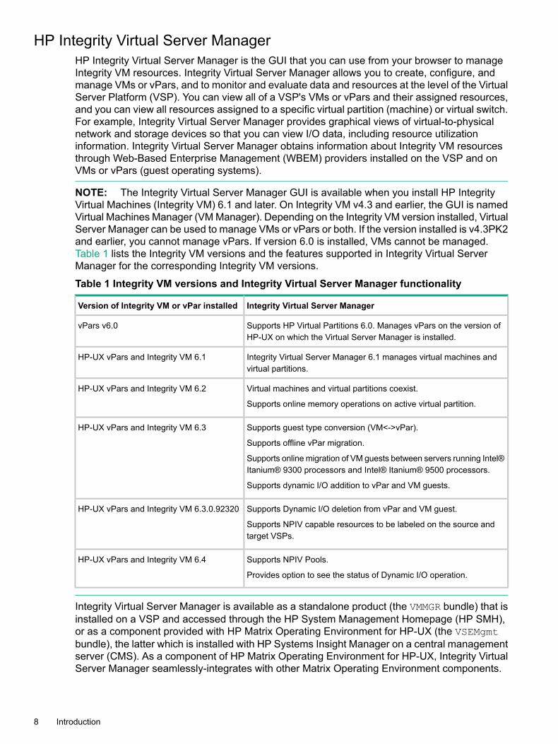
NOTE: The Integrity Virtual Server Manager GUI is available when you install HP IntegrityVirtual Machines (Integrity VM) 6.1 and later. On Integrity VM v4.3 and earlier, the GUI is namedVirtual Machines Manager (VM Manager). Depending on the Integrity VM version installed, VirtualServer Manager can be used to manage VMs or vPars or both. If the version installed is v4.3PK2and earlier, you cannot manage vPars. If version 6.0 is installed, VMs cannot be managed.Table 1 lists the Integrity VM versions and the features supported in Integrity Virtual ServerManager for the corresponding Integrity VM versions.
Table 1 Integrity VM versions and Integrity Virtual Server Manager functionality
Integrity Virtual Server ManagerVersion of Integrity VM or vPar installed
Supports HP Virtual Partitions 6.0. Manages vPars on the version ofHP-UX on which the Virtual Server Manager is installed.
vPars v6.0
Integrity Virtual Server Manager 6.1 manages virtual machines andvirtual partitions.
HP-UX vPars and Integrity VM 6.1
Virtual machines and virtual partitions coexist.
Supports online memory operations on active virtual partition.
HP-UX vPars and Integrity VM 6.2
Supports guest type conversion (VM<->vPar).
Supports offline vPar migration.
Supports online migration of VM guests between servers running Intel®Itanium® 9300 processors and Intel® Itanium® 9500 processors.
Supports dynamic I/O addition to vPar and VM guests.
HP-UX vPars and Integrity VM 6.3
Supports Dynamic I/O deletion from vPar and VM guest.
Supports NPIV capable resources to be labeled on the source andtarget VSPs.
HP-UX vPars and Integrity VM 6.3.0.92320
Supports NPIV Pools.
Provides option to see the status of Dynamic I/O operation.
HP-UX vPars and Integrity VM 6.4
Integrity Virtual Server Manager is available as a standalone product (the VMMGR bundle) that isinstalled on a VSP and accessed through the HP System Management Homepage (HP SMH),or as a component provided with HP Matrix Operating Environment for HP-UX (the VSEMgmtbundle), the latter which is installed with HP Systems Insight Manager on a central managementserver (CMS). As a component of HP Matrix Operating Environment for HP-UX, Integrity VirtualServer Manager seamlessly-integrates with other Matrix Operating Environment components.
8 Introduction

You can access Integrity Virtual Server Manager from a browser, using any of the two web-basedsoftware components (depending on the bundle installed):
• HP System Management Homepage (HP SMH)Integrity Virtual Server Manager is installed separately on any given VSP to manage thatIntegrity VSP and its VMs or vPars. You access Integrity Virtual Server Manager from abrowser that can connect over the network to that VSP. Figure 1 shows how Integrity VirtualServer Manager is configured and used with HP SMH. This configuration is supported onHP-UX 11i v3 and 11i v2.
Figure 1 Integrity Virtual Server Manager with HP SMH
• HP Matrix Operating Environment for HP-UXIntegrity Virtual Server Manager is installed as part of Matrix Operating Environment forHP-UX that runs under HP Systems Insight Manager on a server reserved for use as acentral management server (CMS). The CMS can run on HP-UX or Windows platforms. HPSystems Insight Manager serves as the central point of administration for completeresource-lifecycle management for multi-OS environments. You access Integrity VirtualServer Manager from a browser that can connect over the network to the CMS. The CMSallows you to manage multiple Integrity VMs (VSPs and each of their VMs or vPars) that arediscovered by HP Systems Insight Manager. Figure 2 shows how Integrity Virtual ServerManager is configured and used with HP Matrix Operating Environment (Matrix OE) and HPSystems Insight Manager.
HP Integrity Virtual Server Manager 9

Figure 2 Integrity Virtual Server Manager with HP Systems Insight Manager and theHP Matrix Operating Environment for HP-UX
In this environment, you can use Integrity Virtual Server Manager in seamless integrationwith other Matrix Operating Environment for HP-UX components. These interlinkingcomponents enhance the functionality and flexibility of your virtual server environment. Forexample:
◦ HP Matrix OE visualization provides a framework for visualizing your Virtual ServerEnvironment. All of the systems and workloads that you are authorized to view aredisplayed in a graphical view. The hierarchical relationships between systems and theircurrent utilization metrics can be seen in a single screen. Using HP Matrix OEvisualization, you can manage a pool of multiple-OS, dynamically sizable virtual servers.
10 Introduction
You use HP Matrix OE visualization to access Integrity Virtual Server Manager forviewing and modifying VSP or virtual partition (machine) components.
◦ HP Global Workload Manager (gWLM) is a multiple-system, multiple-OS workloadmanager that serves as an intelligent policy engine in Matrix Operating Environmentfor HP-UX. It simplifies the deployment of automated workload management policiesacross multiple servers, and provides centralized monitoring and reporting and improvedserver utilization to assist in meeting your service level objectives. Using Integrity VirtualServer Manager with Matrix Operating Environment for HP-UX, you can create, view,and modify gWLM policies for VMs or vPars.
◦ HP Capacity Advisor is capacity analysis and planning software that allows you tooptimize the workloads across Matrix Operating Environment for HP-UX for the highestutilization of server resources. From Integrity Virtual Server Manager, you can causeCapacity Advisor to collect and display historical data for a VSP or selected VMs orvPars. Certain Integrity Virtual Server Manager views include utilization meters (bargraphs) that display current utilization data for a resource; you can click the meter toview a screen that provides more detailed historical data. (These meters are visiblewhen using Integrity Virtual Server Manager with HP SMH, but you cannot click themto obtain a Capacity Advisor report.) For more information about using Integrity VirtualServer Manager to collect and view utilization data, see Chapter 7 (page 133). For moreinformation about accessing Capacity Advisor through Integrity Virtual Server Manager,see “Using the Tools menu” (page 83) and “Using the View menu” (page 88).
Other Matrix Operating Environment for HP-UX components include:
◦ Application Discovery
◦ HP Instant Capacity Manager
◦ Partition Manager
◦ WBEM providers (which include the VM Provider and the Utilization Provider, asdescribed in “System and software requirements” (page 13) and other agents.
For more information about Matrix OE concepts and terminology, including a complete listof the components of Matrix Operating Environment for HP-UX, see the HPMatrix OperatingEnvironment 7.5 Getting Started Guide.
Information about HP SMH is available at the following HP SMH website:http://www.hpe.com/info/smhInformation about HP Systems Insight Manager is available at the following HP Systems InsightManager website:http://www.hpe.com/info/sim
Integrity Virtual Server Manager tasksUse Integrity Virtual Server Manager to create and manage VMs or vPars. To take full advantageof Integrity Virtual Server Manager, you can perform the following tasks:• Create, configure, and control VMs or vPars and their resources, such as virtual switches
(vswitches), virtual network devices, and virtual storage devices (Chapter 6)• Monitor VSP and VM or vPar operation (“Using Integrity Virtual Server Manager views and
tabs”)• Modify VM or vPar configurations (“Modifying vPars”)
• Migrate guests from VSP to VSP (“Migrating Guests” (page 106))
Integrity Virtual Server Manager tasks 11

• Collect and view utilization data for VSP, VMs or vPars, and their resources (Chapter 7(page 133))
• Respond to status reports, error messages, and problems concerning VMs or vPars(Appendix A (page 149))
12 Introduction

2 Installing Integrity Virtual Server ManagerThis chapter discusses how to install Integrity Virtual Server Manager on your system or on thesystems you will manage, including setup and software requirements, licensing requirements,and how to set WBEM security credentials.
System and software requirementsSystem requirements for the VSP, VMs, and vPars are described in theHP-UX vPars and IntegrityVM Administrator Guide manual. In addition, see the HP-UX vPars and Integrity VM ReleaseNotes, which are available on the product media. The most up-to-date release notes are availableat the following location (click on the HP Matrix Operating Environment for HP-UX tab):http://www.hpe.com/info/matrixoe/docs
NOTE: Operating system support for VSP and guests varies from release to release of HPIntegrity VM. For information about operating systems supported by a particular release andabout installing supported operating systems on VMs or vPars, see theHP-UX vPars and IntegrityVM Administrator Guide manual.
With use of Integrity Virtual Server Manager in the Matrix OE environment, any managed nodemust have WBEM and the appropriate WBEM credentials to support the visualization andconfiguration features of HP Matrix OE visualization and the collection of utilization data by HPCapacity Advisor. Without WBEM, only Global Workload Manager (gWLM) is functional. Managednodes are systems that the user has instructed HP Systems Insight Manager to manage. ForMatrix OE, all VMs or vPars and their VSP are managed nodes. Systems become managednodes through the Systems Insight Manager “discovery” mechanism. Nodes can be discoveredby Systems Insight Manager in various ways, including automated discovery or manual additionof the node. For example, you can configure and initiate node discovery, and perform numerousother setup tasks, by using the Insight managed system setup wizard. For more information, seethe Insight managed system setup wizard getting started guide, available at the following location:http://www.hpe.com/info/matrixoe/docsTo use Integrity Virtual Server Manager and all its features, install the required WBEM providercomponents on the VSP and on the VM or vPar.In the Matrix OE environment, to install such components on guests, use the Insight managedsystem setup wizard. The wizard allows you to choose whether to install the VM Provider. Thewizard also checks the selected VMs or vPars for the appropriate versions of Utilization Providersoftware and installs the software as needed on supported platforms. (On a VSP, you must installthe appropriate providers manually, using the VSP command line.) For more information, seethe Insight managed system setup wizard getting started guide and the HP Integrity VMdocumentation available from the HP Technical Documentation website (for the HP Integrity VMdocumentation, click on the HP Matrix Operating Environment for HP-UX tab):http://www.hpe.com/info/matrixoe/docsIn the HP SMH environment, install the required provider components on the VM or vPar. Theseprovider components are located in /opt/hpvm/guest-images on the VSP. Subdirectoriescontain the guest management software for each type of guest operating system, including bothHP-UX versions 11i v2 and v3, Windows, and Linux. Each subdirectory includes software providedby HP Integrity VM that should be installed on the guest, including the latest VM Provider software.For more information about installing software components on the VSP and guests, see theHP-UX vPars and Integrity VM Administrator Guide manual and the HP-UX vPars and IntegrityVM Release Notes.The WBEM provider components are the VM Provider and the Utilization Provider:
System and software requirements 13

• The VM Provider provides VSP and guest configuration data. This information is deliveredusing WBEM. To use Integrity Virtual Server Manager to view configuration data, install theVM Provider (VMProvider bundle) that is provided with Integrity VM. Install the VM Provideron the VSP and on each VM or vPar when you install the HP Integrity VM product. If youupgrade Integrity VM, be sure to keep the VM Provider up to date, too. If the VM Providerversion does not match the Integrity VM version, the Integrity Virtual Server Manager mightnot work as expected.As for guests, the VM provider is required to view guest configuration data. The VM Providerand Integrity VM versions need not match. A guest's VM Provider can be an earlier versionthan that of the Integrity VM running on the VSP. However, HP recommends upgrading theguests to the latest version of VM Provider available, even if the latest available providerversion is greater than the version of the Integrity VM currently installed on the VSP. Whenthe VSP Integrity VM is upgraded, you are not required to upgrade the VM Provider on eachof the guests, but HP recommends upgrading the VM Providers on the guests to at leastmatch the version of the Integrity VM on the VSP.To install the VM Provider on the VSP and guests, install the appropriate provider softwarefrom the operating system media or the Integrity VM guest management software kit.
• The Utilization Provider gathers utilization statistics for CPU, memory, disk, and LAN. Thisinformation is delivered using WBEM and gathers data using a daemon (/usr/sbin/utild).You must install the Utilization Provider on the VSP and on each VM or vPar.
Installing Integrity Virtual Server Manager on HP Systems Insight ManagerOn HP Systems Insight Manager, system requirements for installing Integrity Virtual ServerManager are the same as requirements for installing Matrix Operating Environment for HP-UX.You must have a license for at least one other component of Matrix Operating Environment forHP-UX, such as HP Matrix OE visualization. You cannot access the functionality in IntegrityVirtual Server Manager unless you have a license for, and have installed Integrity VM on, at leastone system to be managed through your licensed Matrix Operating Environment for HP-UXcomponents.For information about system requirements and installation instructions, see the HP MatrixOperating Environment Integrity CMS Installation and Configuration Guide and the Insightmanaged system setup wizard getting started guide. This and other similar documentation isavailable from the HP Technical Documentation website:http://www.hpe.com/info/matrixoe/docs
NOTE: Do not install the VMMGR bundle (the bundle containing the Integrity Virtual ServerManager HP SMH plug-in) from the software depot onto the HP Systems Insight Manager CMS.For centralized Integrity VM management capabilities, install the VSEMgmt bundle (containingthe Integrity Virtual Server Manager for HP Systems Insight Manager) from the software bundle.
Installing Integrity Virtual Server Manager on HP SMHOn HP SMH, Integrity Virtual Server Manager must be installed separately on a VSP.Integrity Virtual Server Manager 6.4 requires JDK60 or later for installation. Ensure that you haveinstalled JDK60 or later before installing Integrity Virtual Server Manager 6.4.Download the Integrity Virtual Server Manager software depot from the following location:www.hpe.com/support/softwaredepotAfter downloading the depot, install the software. As a privileged user, execute the followingcommand, where path-to-depot-file is the full path specification to the depot file:# swinstall -x mount_all_filesystems=false -s path-to-depot-file VMMGR
14 Installing Integrity Virtual Server Manager
To determine the version of Integrity Virtual Server Manager currently installed, enter the followingcommand:#/usr/sbin/swlist VMMGR
NOTE: Beginning with the HP-UX 11i v3 March 2009 Operating Environment Update Release(OEUR), you can optionally install Integrity Virtual Server Manager on HP SMH as part of theVSE-OE or DC-OE.
Licensing requirementsThe licensing requirements for Integrity Virtual Server Manager on HP SMH include the following:On HP SMH, Integrity Virtual Server Manager is installed separately on a VSP. You must havea license for Integrity VM and have Integrity VM installed on that VSP. A separate license forIntegrity Virtual Server Manager is not required.For information about licensing, see the readme file in the /opt/vmmgr/src directory (HPSMH).You must purchase licenses for any software you run in a VM or vPar, including the HP-UXoperating system and any HP or third-party layered software. You can purchase the licenses forHP software under the HP Virtualization Licensing program. For more information, contact yourHP representative.
• On HP Systems Insight Manager, Integrity Virtual Server Manager is included with MatrixOperating Environment for HP-UX and is installed when Matrix OE is installed. To makeIntegrity Virtual Server Manager operational, you must have a valid license installed for atleast one other component of Matrix Operating Environment for HP-UX (for example, HPMatrix OE visualization) and one license installed for Integrity VM on at least one VSP.You cannot access the functionality in Integrity Virtual Server Manager unless you have alicense for Integrity VM and have Integrity VM installed on at least one system to be managedthrough your licensed Matrix Operating Environment for HP-UX components.
Setting security credentialsTo display the full range of data about each VM or vPar in Integrity Virtual Server Manager, youmust have WBEM-recognized credentials for each VM or vPar. A user name and password arerequired to collect resource utilization and other data, such as the status of the installed operatingsystem. This data is available only from a WBEM provider on the VSP or VM (vPar). The WBEMproviders are the tools used to gather data about the VM or vPar and the VSP. The user interfaceuses this information to show various kinds of system status.You can set credentials by specifying a default user name and password combination for any orall VMs or vPars. You can also override the default user name or password on a case-by-casebasis.
NOTE:• For a given VM or vPar, if no user name or password is specified, the default is used.
• If a password is specified but a user name is not, the default user name is used with thepassword override. This allows a system administrator to use the same user name butdifferent passwords for each VM or vPar.
When running Integrity Virtual Server Manager with Matrix Operating Environment for HP-UX,Systems Insight Manager is responsible for managing the credentials needed for using WBEMproviders on the VSP and on VMs or vPars. When running Integrity Virtual Server Manager underHP SMH, HP SMH manages credentials and access for the VSP on which HP SMH is running;credentials for each VM or vPar are managed by Integrity Virtual Server Manager.
Licensing requirements 15

The method for setting WBEM credentials depends on whether you are using HP Systems InsightManager or HP SMH.
Setting WBEM credentials in HP Systems Insight ManagerAny VMs or vPars that are not managed nodes do not have any credentials available, and IntegrityVirtual Server Manager cannot contact them. These machines are displayed, but some of theinformation that can be gathered from the managed nodes is not displayed for non-managednodes.You can set credentials in HP Systems Insight Manager for a global configuration across multiplesystems by selecting Options→Protocol Settings→Global Protocol Settings...; for a singlemanaged node, set credentials by selecting Options→Protocol Settings→System ProtocolSettings.... Integrity Virtual Server Manager requires that the proper WBEM credentials (a validuser name and password) be set in those option pages. Without WBEM, the HP Matrix OEvisualization and HP Capacity Advisor functionality will not be available; only Global WorkloadManager (gWLM) is functional.With HP Systems Insight Manager, you can set the credentials when you first launch HP SystemsInsight Manager after installation by using the HP Systems Insight Manager First Time Wizard.For information about setting credentials, see the HP Matrix Operating Environment IntegrityCMS Installation and Configuration Guide.
Setting WBEM credentials in HP SMHYou must set WBEM credentials for VMs or vPars in HP SMH. This allows Integrity Virtual ServerManager to collect utilization data and operating system information on the VM or vPar. Storedcredentials are specific to the user logged in to HP SMH. Two users who are logged in withdifferent user names do not share credentials.When you log into SMH without having already set the WBEM credentials and saving them inthe file system, the Set WBEM Credentials for VM or vPar page is displayed. When you createa new VM or vPar, you must add credentials for that VM or vPar by selecting Modify→WBEMCredentials... from the Integrity Virtual Server Manager menu bar, which displays the samepage. Figure 3 shows an example of the Set WBEM Credentials for VM or vPar page.
Figure 3 HP SMH: Set WBEM Credentials page
16 Installing Integrity Virtual Server Manager
On this page, you can set one user name and password combination for all VMs or vPars, oryou can set them individually for one or more VMs or vPars. If you set the credentials for somebut not all of the individual systems, Integrity Virtual Server Manager does not collect utilizationdata and operating system information for the excluded systems.You can also save the user name and password entries in obscured format in the file system.This allows you to use the same setting each time you enter Integrity Virtual Server Managerthrough HP SMH. To save these entries, select the Save user name and password settingsin the file system check box, and then click OK. This information is obfuscated before beingstored.If you do not want to provide this security information for the current session, clickCancel. IntegrityVirtual Server Manager continues without collecting this data. If you do not want to provide thisadditional data for subsequent uses of Integrity Virtual Server Manager, and you do not want tobe prompted for it on each entry into Integrity Virtual Server Manager, make sure all entries onthe page are blank, select the check box to save the credentials to file, and click OK. Emptycredentials are stored, and this prevents the WBEM credentials page from being displayed onsubsequent entries into Integrity Virtual Server Manager.If you require the additional security provided by certificate validation, you can turn on SSLcertificate validation by checking the Require trusted certificates check box. If this box ischecked, you must store the valid certificates for the VMs or vPars in a keystore on the VSP toindicate that connections to those VMs or vPars are trusted; otherwise, some information is notdisplayed by Integrity Virtual Server Manager. For example, if a certificate is missing, utilizationmeters are labeled No Data. For more information about trusted certificates and how to storethem in a keystore on the VSP, see “Trusted certificates” (page 18).You can use the basic features of the HP SMH version of Integrity Virtual Server Manager withoutexposing user credentials or configuration data on the local network. In this case, you see asubset of the potential information that the Integrity Virtual Server Manager can display. To haveall data displayed, the following steps are required.
NOTE: Displaying all the information about the VMs or vPars' configuration exposes thecredentials of a connecting user.
1. Create a nonlogin, nonprivileged account on each VM or vPar to which Integrity VirtualServer Manager might connect and whose credentials can be intercepted on the network.Although these credentials are restricted to nonlogin capabilities, they can also be used togain access to other data or actions available using WBEM and other nonlogin services,including those from additional providers that are registered on the system.
2. Optional, for additional security: If local policy is to avoid exposure of any account credentialson your network, or if you do not want to expose the VM or vPar configuration data, thenconfigure an SSH or IPSec tunnel from the VSP system to each VM or vPar for port 5989(HP WBEM Services).
The following types of information require credentials for each VM or vPar for which informationis to be gathered:• Operating System: If the required credentials are not set for a VM or vPar, Integrity Virtual
Server Manager cannot contact the machine. Integrity Virtual Server Manager displays theexpected operating system (if the operating system was set during configuration of the VMor vPar, or if the guest operating system on the VM or vPar has been booted). If thecredentials are set and the VM or vPar is running with the proper provider, Integrity VirtualServer Manager displays the operating system and version number.
• Utilization: If the required credentials are not set for a VM or vPar, the utilization meters forVM-specific or vPar-specific items are dimmed. (Meters specific to a VM or vPar are locatedon such Integrity Virtual Server Manager pages as the VSP Virtual Servers tab, the VMsor vPars Properties Network and VMs or vPars Properties Storage tabs, and the VMsor vPars Properties General tab. For more information about these tabs, see Chapter 4
Setting security credentials 17

(page 29).) Meters for the VSP and VSP resources are still available if the VSP's WBEMUtilization Provider is running.The data is a 5-minute average that is calculated and updated on 5-minute boundaries.When a utilization meter is dimmed, a label next to the meter indicates the probable cause.These labels and status indicators are described in “Utilization meter status/error information”(page 151).Virtual LAN interface I/O utilization on the VM or vPar Properties Network tab: For a VMor vPar with invalid credentials, either the No Perm. or No Data label appears next to themeter. The page still displays whatever information is available from the VSP, such as thestatus and the bus, device, and function numbers for a virtual LAN interface. For a VM orvPar with valid credentials, Integrity Virtual Server Manager displays I/O utilization data foreach virtual LAN interface and for VM or vPar aggregated LAN interfaces.Virtual storage device I/O utilization on the VM or vPar Properties Storage tab: For a VMor vPar with invalid credentials, either the No Perm. or No Data label appears next to themeter. The page still displays whatever information is available from the VSP, such as thevirtual device type and the bus, device, and target numbers for the virtual storage device.For a VM or vPar with valid credentials, Integrity Virtual Server Manager displays I/O utilizationdata for each virtual storage device and for VM or vPar aggregated storage interfaces.
• Virtual LAN (VLAN) interface name and status on the Network tab: This status is displayedfor a VM or vPar with valid credentials, but invalid credentials will return an unknown LANstatus and utilization. It might display whatever information is available, for example, thebus, dev, or the fcn number for the VLAN interface.
To change the WBEM credentials settings for VMs or vPars, return to the SetWBEMCredentialsfor VMs or vPars page by selecting Modify→WBEM Credentials.... You do not need to selecta VM or vPar before setting credentials.
IMPORTANT: After you enter the data, save it by clicking OK. Otherwise, the data is clearedwhen the session ends.
Trusted certificatesIf you require the additional security provided by certificate validation you can turn on SSLcertificate validation by selecting the Require trusted certificates check box on the IntegrityVirtual Server Manager Set WBEMCredentials for VMs or vPars page. With this setting turnedon, the client Certificate Trust Store must include the server certificates from the VMs or vPars;otherwise, Integrity Virtual Server Manager cannot obtain certain information from the VMs orvPars. If your environment does not require the additional security provided by certificate validation,you can leave certificate validation turned off.To enable SSL certificate validation in Integrity Virtual Server Manager, you must export theserver certificates from the WBEM services providers on the VMs or vPars, and import thosecertificates into the keystore on the VSP where Integrity Virtual Server Manager is running. Thiskeystore is shared between Partition (machine) Manager and Integrity Virtual Server Manager.Certificates in this keystore are trusted by both Partition (Machine) Manager and Integrity VirtualServer Manager.To get the certificate file from the WBEM services provider, follow these steps:
18 Installing Integrity Virtual Server Manager

1. Locate the WBEM services provider certificate file (cert.pem) on the VM or vPar to whichyou want to connect. To find the correct file, open the WBEM services Provider configurationfile, which can be found in the following locations:• For Windows:
%PEGASUS_HOME%\cimserver_current.conf
• For HP-UX:$PEGASUS_HOME/cimserver_current.conf
(The default value for PEGASUS_HOME on HP-UX is /var/opt/wbem.)
The location of the server certificate file is configured by the sslCertificateFilePathsetting. If this value is not set in the configuration file, the default values are as follows:
• For Windows:%PEGASUS_HOME%\server.pem
• For HP-UX:/etc/opt/hp/sslshare/cert.pem
2. Copy the certificate file (cert.pem or server.pem) to the VSP where Integrity VirtualServer Manager is running.
NOTE: Copy the certificate file to a temporary directory (not to the sslshare directory)on the VSP. Do not overwrite the existing cert.pem or server.pem file in the sslsharedirectory on the VSP.
3. To import the certificate file, enter the following command on the VSP:$ JAVA_HOME/bin/keytool -import -alias server_hostname \-file cert.pem \ -keystore /etc/opt/hp/sslshare/parmgr.keystore
Discovering data when setting new WBEM credentialsWhen you set new WBEM credentials from the Integrity Virtual Server Manager Modify menuand click OK, the page to which you return is updated using the new credentials. However,especially when Integrity Virtual Server Manager must retrieve data from a large number of VMsor vPars, some of the data might not yet be updated when the page displays in full (instead, theold data is still displayed). With the exception of data displayed by utilization meters, the newdata (such as the VM or vPar guest OS version) is not seen until the page refreshes again. Theutilization meters update immediately after Integrity Virtual Server Manager retrieves the utilizationdata; refreshing the page is not required for updating that data.
Setting security credentials 19

20
3 Accessing and Navigating Integrity Virtual ServerManager
You access Integrity Virtual Server Manager through a web browser. This chapter explains howto access Integrity Virtual Server Manager from HP SMH and HP SIM. This chapter also explainshow to access Integrity Virtual Server Manager help. Information about possible access failuresand the messages that might be seen is included in Appendix A (page 149).
Accessing Integrity Virtual Server Manager from Matrix OperatingEnvironment for HP-UX
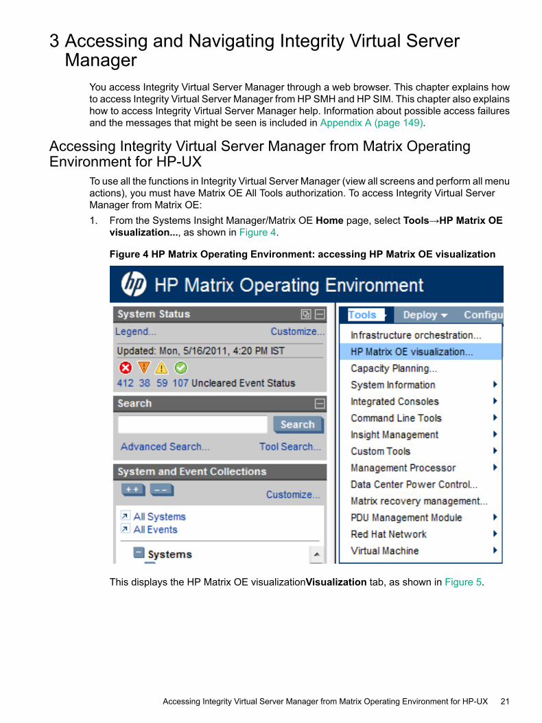
To use all the functions in Integrity Virtual Server Manager (view all screens and perform all menuactions), you must have Matrix OE All Tools authorization. To access Integrity Virtual ServerManager from Matrix OE:1. From the Systems Insight Manager/Matrix OE Home page, select Tools→HP Matrix OE
visualization..., as shown in Figure 4.
Figure 4 HP Matrix Operating Environment: accessing HP Matrix OE visualization
This displays the HP Matrix OE visualizationVisualization tab, as shown in Figure 5.
Accessing Integrity Virtual Server Manager from Matrix Operating Environment for HP-UX 21

Figure 5 HP Matrix OE visualization — Visualization tab
2. The first time you start HP Matrix OE visualization, the Visualization tab appears with thedefault Physical and Virtual perspective, which shows all physical and virtual nodes ingraphical compartments. When you start HP Matrix OE visualization any time after, thesoftware checks whether you had previously set a default view by modifying user preferences(modify user preferences by selecting Configure→User Preferences... from the HP MatrixOE visualization menu bar). If you set a collection such as VSPs, HP Matrix OE visualizationdisplays the collection for all VSPs and VMs or vPars.The Perspective menu allows you to choose a view comprised solely of VSPs and VMs orvPars (both HP Integrity VM and VMware ESX, if both products are present among theresources). Select Virtual Machine from the drop-down menu, as shown in Figure 6.
Figure 6 Selecting VM or vPar perspective
22 Accessing and Navigating Integrity Virtual Server Manager
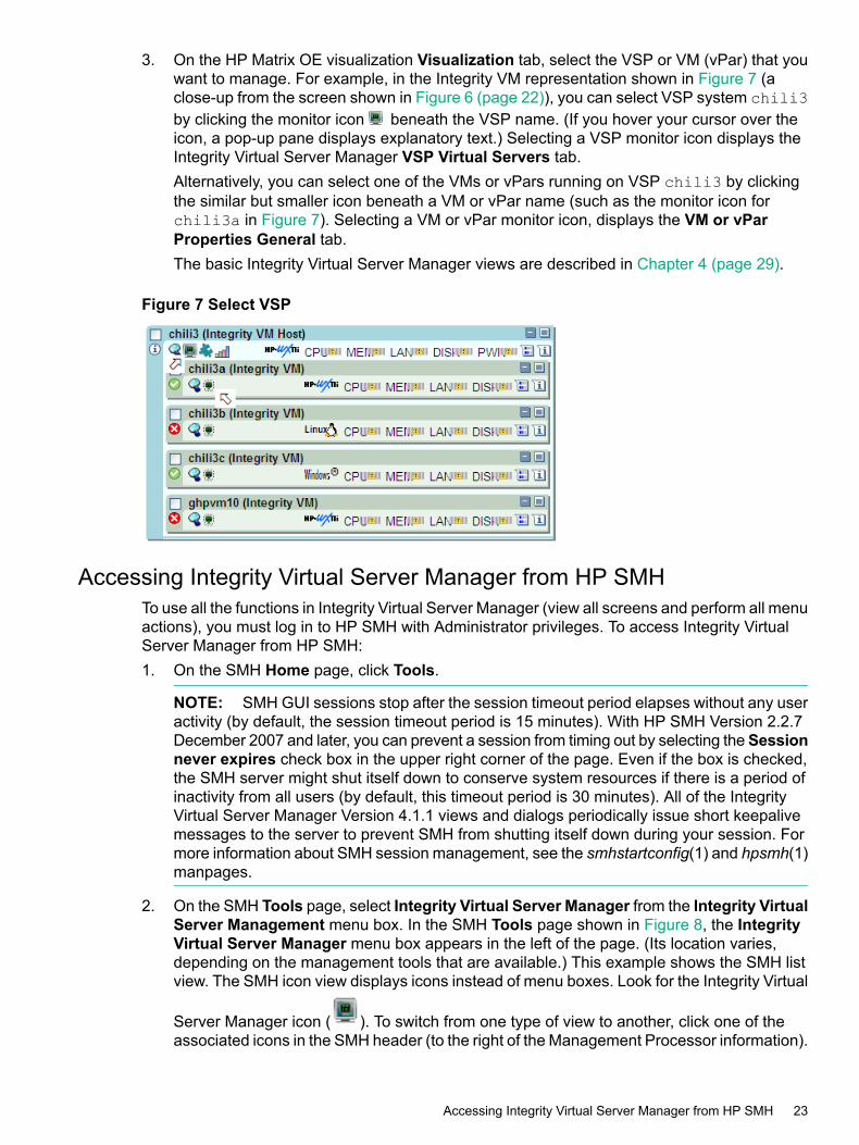
3. On the HP Matrix OE visualization Visualization tab, select the VSP or VM (vPar) that youwant to manage. For example, in the Integrity VM representation shown in Figure 7 (aclose-up from the screen shown in Figure 6 (page 22)), you can select VSP system chili3by clicking the monitor icon beneath the VSP name. (If you hover your cursor over theicon, a pop-up pane displays explanatory text.) Selecting a VSP monitor icon displays theIntegrity Virtual Server Manager VSP Virtual Servers tab.Alternatively, you can select one of the VMs or vPars running on VSP chili3 by clickingthe similar but smaller icon beneath a VM or vPar name (such as the monitor icon forchili3a in Figure 7). Selecting a VM or vPar monitor icon, displays the VM or vParProperties General tab.The basic Integrity Virtual Server Manager views are described in Chapter 4 (page 29).
Figure 7 Select VSP
Accessing Integrity Virtual Server Manager from HP SMHTo use all the functions in Integrity Virtual Server Manager (view all screens and perform all menuactions), you must log in to HP SMH with Administrator privileges. To access Integrity VirtualServer Manager from HP SMH:1. On the SMH Home page, click Tools.
NOTE: SMH GUI sessions stop after the session timeout period elapses without any useractivity (by default, the session timeout period is 15 minutes). With HP SMH Version 2.2.7December 2007 and later, you can prevent a session from timing out by selecting the Sessionnever expires check box in the upper right corner of the page. Even if the box is checked,the SMH server might shut itself down to conserve system resources if there is a period ofinactivity from all users (by default, this timeout period is 30 minutes). All of the IntegrityVirtual Server Manager Version 4.1.1 views and dialogs periodically issue short keepalivemessages to the server to prevent SMH from shutting itself down during your session. Formore information about SMH session management, see the smhstartconfig(1) and hpsmh(1)manpages.
2. On the SMH Tools page, select Integrity Virtual Server Manager from the Integrity VirtualServer Management menu box. In the SMH Tools page shown in Figure 8, the IntegrityVirtual Server Manager menu box appears in the left of the page. (Its location varies,depending on the management tools that are available.) This example shows the SMH listview. The SMH icon view displays icons instead of menu boxes. Look for the Integrity Virtual
Server Manager icon ( ). To switch from one type of view to another, click one of theassociated icons in the SMH header (to the right of the Management Processor information).
Accessing Integrity Virtual Server Manager from HP SMH 23
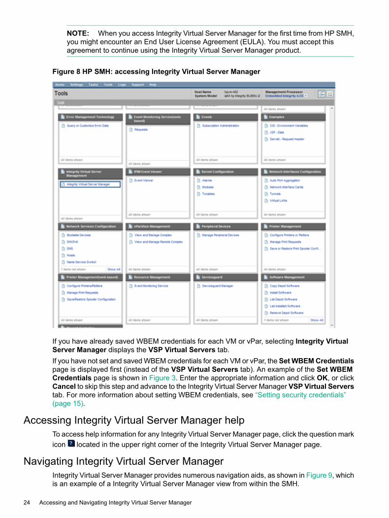
NOTE: When you access Integrity Virtual Server Manager for the first time from HP SMH,you might encounter an End User License Agreement (EULA). You must accept thisagreement to continue using the Integrity Virtual Server Manager product.
Figure 8 HP SMH: accessing Integrity Virtual Server Manager
If you have already saved WBEM credentials for each VM or vPar, selecting Integrity VirtualServer Manager displays the VSP Virtual Servers tab.If you have not set and saved WBEM credentials for each VM or vPar, the SetWBEMCredentialspage is displayed first (instead of the VSP Virtual Servers tab). An example of the Set WBEMCredentials page is shown in Figure 3. Enter the appropriate information and click OK, or clickCancel to skip this step and advance to the Integrity Virtual Server Manager VSP Virtual Serverstab. For more information about setting WBEM credentials, see “Setting security credentials”(page 15).
Accessing Integrity Virtual Server Manager helpTo access help information for any Integrity Virtual Server Manager page, click the question markicon located in the upper right corner of the Integrity Virtual Server Manager page.
Navigating Integrity Virtual Server ManagerIntegrity Virtual Server Manager provides numerous navigation aids, as shown in Figure 9, whichis an example of a Integrity Virtual Server Manager view from within the SMH.
24 Accessing and Navigating Integrity Virtual Server Manager
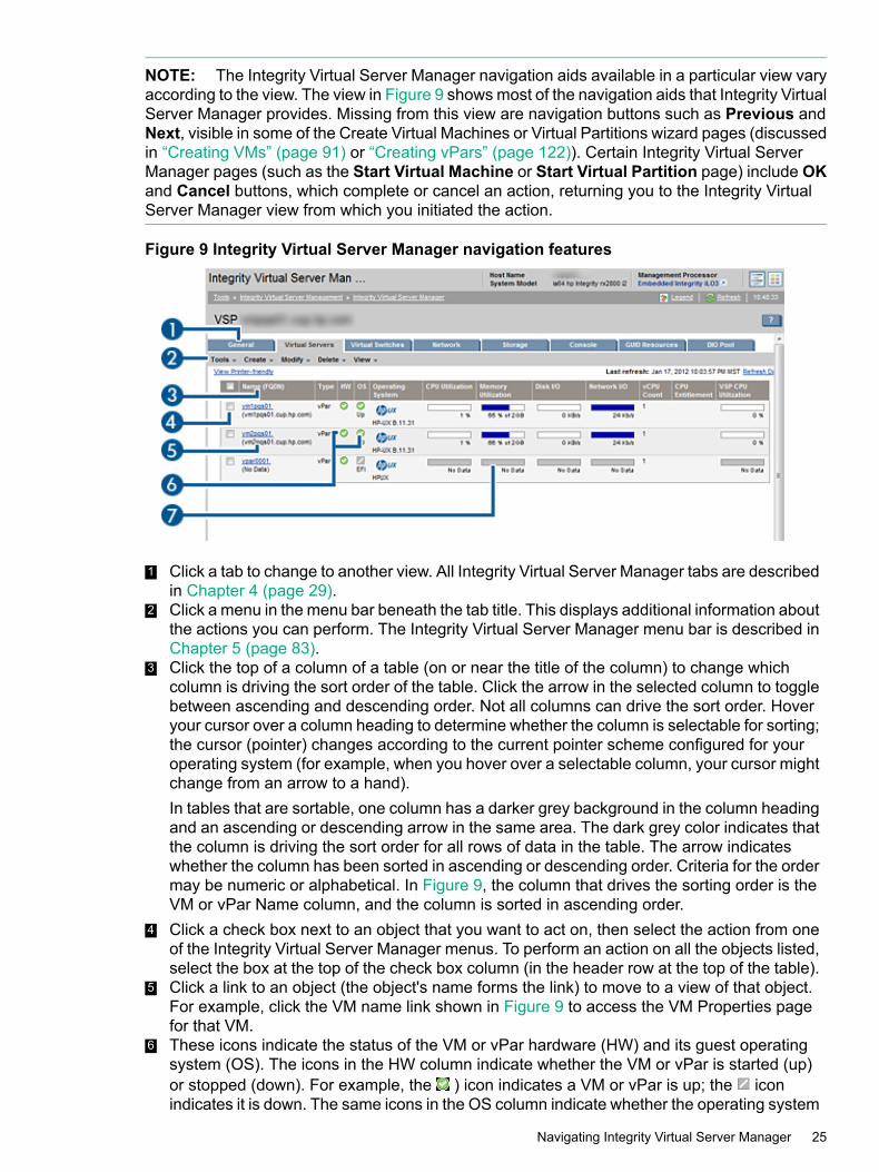
NOTE: The Integrity Virtual Server Manager navigation aids available in a particular view varyaccording to the view. The view in Figure 9 shows most of the navigation aids that Integrity VirtualServer Manager provides. Missing from this view are navigation buttons such as Previous andNext, visible in some of the Create Virtual Machines or Virtual Partitions wizard pages (discussedin “Creating VMs” (page 91) or “Creating vPars” (page 122)). Certain Integrity Virtual ServerManager pages (such as the Start Virtual Machine or Start Virtual Partition page) include OKand Cancel buttons, which complete or cancel an action, returning you to the Integrity VirtualServer Manager view from which you initiated the action.
Figure 9 Integrity Virtual Server Manager navigation features
1 Click a tab to change to another view. All Integrity Virtual Server Manager tabs are describedin Chapter 4 (page 29).
2 Click a menu in the menu bar beneath the tab title. This displays additional information aboutthe actions you can perform. The Integrity Virtual Server Manager menu bar is described inChapter 5 (page 83).
3 Click the top of a column of a table (on or near the title of the column) to change whichcolumn is driving the sort order of the table. Click the arrow in the selected column to togglebetween ascending and descending order. Not all columns can drive the sort order. Hoveryour cursor over a column heading to determine whether the column is selectable for sorting;the cursor (pointer) changes according to the current pointer scheme configured for youroperating system (for example, when you hover over a selectable column, your cursor mightchange from an arrow to a hand).In tables that are sortable, one column has a darker grey background in the column headingand an ascending or descending arrow in the same area. The dark grey color indicates thatthe column is driving the sort order for all rows of data in the table. The arrow indicateswhether the column has been sorted in ascending or descending order. Criteria for the ordermay be numeric or alphabetical. In Figure 9, the column that drives the sorting order is theVM or vPar Name column, and the column is sorted in ascending order.
4 Click a check box next to an object that you want to act on, then select the action from oneof the Integrity Virtual Server Manager menus. To perform an action on all the objects listed,select the box at the top of the check box column (in the header row at the top of the table).
5 Click a link to an object (the object's name forms the link) to move to a view of that object.For example, click the VM name link shown in Figure 9 to access the VM Properties pagefor that VM.
6 These icons indicate the status of the VM or vPar hardware (HW) and its guest operatingsystem (OS). The icons in the HW column indicate whether the VM or vPar is started (up)or stopped (down). For example, the ) icon indicates a VM or vPar is up; the iconindicates it is down. The same icons in the OS column indicate whether the operating system
Navigating Integrity Virtual Server Manager 25

is running. The icon in the OS column indicates that the VM is in a suspended state. Inthis particular view (the VSP Virtual Servers tab), if a VM is migrating, an icon indicates thedirection of migration. In the last row of the table, the icon indicates the VM is migratingto another VSP. For more information about migration status icons, see “VSP Virtual Serverstab” (page 33). The meanings of these and other status icons are summarized in “Statusindicators” (page 151).
7 Using Integrity Virtual Server Manager with Matrix Operating Environment, you can click autilization meter to view a snapshot of Capacity Advisor historical data; this feature is notprovided when using Integrity Virtual Server Manager from HP SMH. For information aboutusing Integrity Virtual Server Manager to collect and view utilization data, see Chapter 7(page 133).
NOTE: Avoid using your browser's Back and Forward buttons in Integrity Virtual ServerManager. When you use these buttons, Integrity Virtual Server Manager cannot identify that youhave changed to a different view. This can cause problems, including incorrect display of objectsselected in the current view. Instead, use the links and navigation buttons provided by IntegrityVirtual Server Manager.
If you navigate from one Integrity Virtual Server Manager view to another (for example, from VSPview to VM or vPar Properties view), click the Go back link in the new view (and on anysubsequent tabs you navigate to in that same view) to return to the previous Integrity VirtualServer Manager view. For example, if you navigate from the VSP view to the VM or vPar Propertiesview or to the Vswitch Properties view, clicking the Go back link returns you to the VSP view.If you navigate from the VM or vPar Properties view to the VSP view or to the Vswitch Propertiesview, clicking the Go back link returns you to the VM or vPar Properties view.Using Integrity Virtual Server Manager from Matrix Operating Environment, if the Integrity VirtualServer Manager view was accessed directly from HP Matrix OE visualization, clicking the Goback link returns you to HP Matrix OE visualization (as indicated in Figure 9); clicking the Goback link on any tab that you navigate to in the same view also returns you to the HP Matrix OEvisualization. For more information about returning to HP Matrix OE visualization from IntegrityVirtual Server Manager (or, if you are using HP SMH, about returning to the HP SMH Homepage),see “Returning to the HP SMH Homepage” (page 26).
Returning to the HP SMH HomepageWith HP Matrix Operating Environment, to access HP Matrix OE visualization from a IntegrityVirtual Server Manager view in which the Go back link currently directs you to another IntegrityVirtual Server Manager view, you can do one of the following:• From the HP Matrix Operating Environment menu bar (top menu bar), select Tools→HP
Matrix OE visualization.... Alternatively, select the All VSE Resources link in the left-handnavigation pane (System and Event Collections→Systems→Shared→Systems byType→All VSE Resources). To access the top menu bar or left-hand navigation pane, yourIntegrity Virtual Server Manager view must not be maximized (using the Maximize link inthe top right corner). If your view is maximized, return to the view that includes the top menubar by clicking Restore Size in the top right corner of the maximized Integrity Virtual ServerManager view.
• Continue using the Go back link until you return to the Integrity Virtual Server Manager viewthat you accessed originally from the HP Matrix OE visualization, at which point you canclick the Go back to HP Matrix OE visualization link.
Click Home from the HP SMH menu bar to return to the HP SMH Homepage if you are usingIntegrity Virtual Server Manager from HP SMH.
26 Accessing and Navigating Integrity Virtual Server Manager

NOTE: Avoid using your browser's Back and Forward buttons in Integrity Virtual ServerManager. Instead, use the links and navigation buttons provided by Integrity Virtual ServerManager, as described in this section and “Navigating Integrity Virtual Server Manager” (page 24).
Returning to the HP SMH Homepage 27

28

4 Using Integrity Virtual Server Manager views and tabsIntegrity Virtual Server Manager provides three basic views, each with several tabs, as describedin the following sections.You can print any of the VSP or vPar or VM tabs by clicking View Printer-friendly beneath theIntegrity Virtual Server Manager menu bar, on the left side of the page. This redisplays the tabin a format suitable for printing. To print the tab, click Print. To switch back, click View Normal.You can update the data on certain pages by clicking Refresh Data beneath the Integrity VirtualServer Manager menu bar, on the right side of the page. In general, Integrity Virtual ServerManager tabbed views are refreshed automatically every five minutes. An indicator on thesevisualization pages notifies you when the data was last refreshed. Integrity Virtual Server Managerscreens that display configuration data are updated instantaneously when you use Integrity VirtualServer Manager to change the related configuration parameters. However, when changes to theVM or vPar I/O configuration are made using tools other than Integrity Virtual Server Manager(such as adding or removing I/O devices by using the VSP command line), the updatedconfiguration data is not shown until the screen is refreshed. Some dialog screens, such as theCreate Virtual Machine or Create Virtual Partition wizard Add Storage Device and theModify→Add Storage Device to VM or vPar... screens, include a Refresh Data link that youcan use to manually refresh data.
NOTE: The figures in this chapter and in the remainder of the manual display views seen fromHP Matrix Operating Environment. Views in HP SMH might differ slightly. Differences are noted.In addition, the examples display maximized window views to give more focus to the IntegrityVirtual Server Manager window (eliminating the Matrix Operating Environment system statuspane available on the left of the page and the Systems Insight Manager/HP Matrix OperatingEnvironment header and menu bar on the top of the page). Select the maximized view by clickingMaximize in the top right corner of the page. To return to the original view, click Restore Sizein the top right corner of the maximized page. The maximize feature is not provided by HP SMHbut is not needed; HP SMH provides a full-window Integrity Virtual Server Manager view.
VSP viewYou can access the Integrity Virtual Server Manager VSP view directly from SMH or from otherIntegrity Virtual Server Manager views that include a link to the VSP, such as the VM or vParProperties General tab. Figure 10 shows a typical VSP view in Integrity Virtual Server Manager.Tabs available from the VSP view are described in the text that follows. Subsequent sectionsdescribe each tab in more detail.
VSP view 29
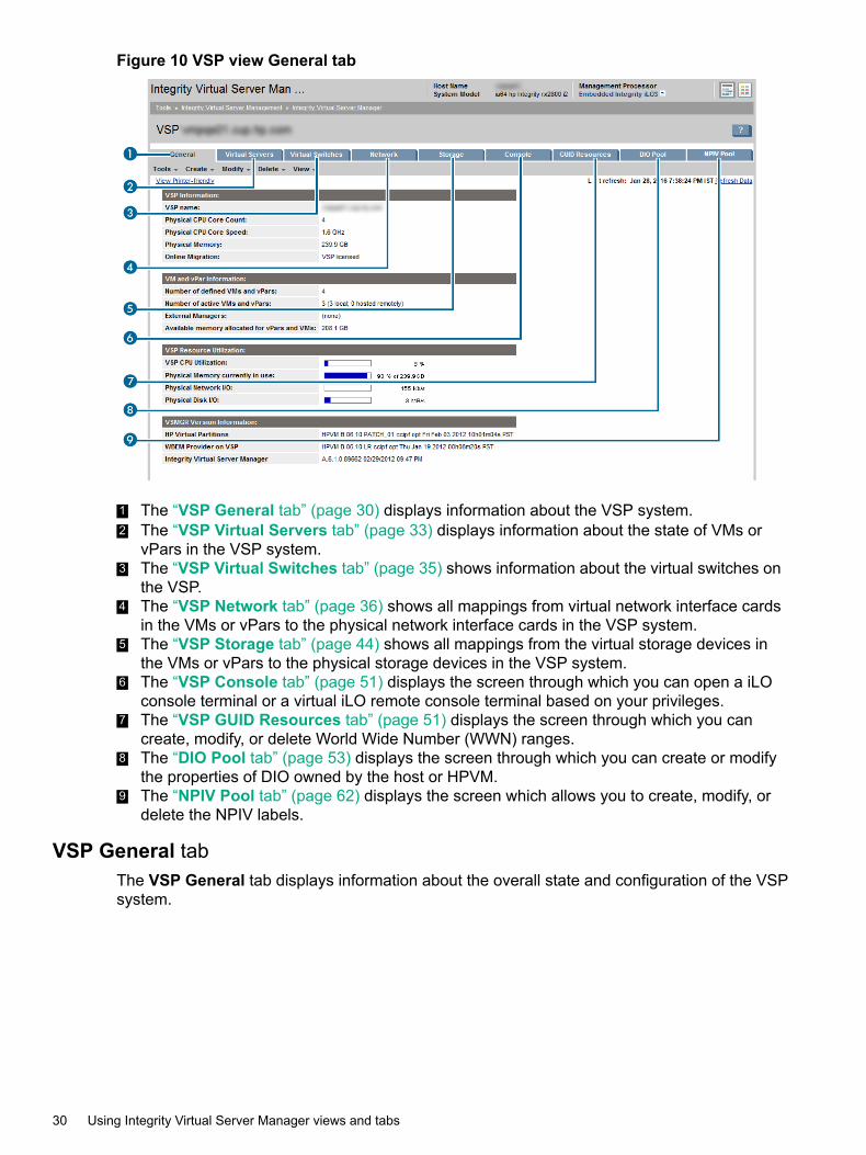
Figure 10 VSP view General tab
1 The “VSP General tab” (page 30) displays information about the VSP system.2 The “VSP Virtual Servers tab” (page 33) displays information about the state of VMs or
vPars in the VSP system.3 The “VSP Virtual Switches tab” (page 35) shows information about the virtual switches on
the VSP.4 The “VSP Network tab” (page 36) shows all mappings from virtual network interface cards
in the VMs or vPars to the physical network interface cards in the VSP system.5 The “VSP Storage tab” (page 44) shows all mappings from the virtual storage devices in
the VMs or vPars to the physical storage devices in the VSP system.6 The “VSP Console tab” (page 51) displays the screen through which you can open a iLO
console terminal or a virtual iLO remote console terminal based on your privileges.7 The “VSP GUID Resources tab” (page 51) displays the screen through which you can
create, modify, or delete World Wide Number (WWN) ranges.8 The “DIO Pool tab” (page 53) displays the screen through which you can create or modify
the properties of DIO owned by the host or HPVM.9 The “NPIV Pool tab” (page 62) displays the screen which allows you to create, modify, or
delete the NPIV labels.
VSP General tabThe VSP General tab displays information about the overall state and configuration of the VSPsystem.
30 Using Integrity Virtual Server Manager views and tabs
Quick reference
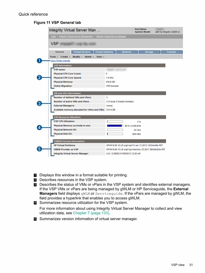
Figure 11 VSP General tab
1 Displays this window in a format suitable for printing.2 Describes resources in the VSP system.3 Describes the status of VMs or vPars in the VSP system and identifies external managers.
If the VSP VMs or vPars are being managed by gWLM or HP Serviceguide, the ExternalManagers field displays gWLM or Serviceguide. If the vPars are managed by gWLM, thefield provides a hyperlink that enables you to access gWLM.
4 Summarizes resource utilization for the VSP system.For more information about using Integrity Virtual Server Manager to collect and viewutilization data, see Chapter 7 (page 133).
5 Summarizes version information of virtual server manager.
VSP view 31
Screen details
VSP Information
• VSP name: The hostname of the VSP system (as well as the nPartition name and link toPartition Manager for this nPartition, if the VSP system is contained within an nPartition).
• Resource inventory.
Physical CPU Core Count: The number of processors.◦◦ Physical CPU Core Speed: The speed of processors.
◦ Physical Memory: The amount of memory.
◦ Online Migration: Indicates whether the VSP is enabled and licensed to support onlinemigration of VMs. The second column in the following table shows what the status fielddisplays, based on the state of the VSP listed in the first column:
Table 2 Online migration status
Online migration statusVSP state for online migration
Host disabledDisabled
Host licensedEnabled and licensed
Host not licensedEnabled and unlicensed
The licensing is included with a bundle that must be installed on the VSP. For moreinformation about enabling and licensing the VSP, see the HP-UX vPars and IntegrityVM Administrator Guide manual.
VM and vPar Information
• Number of defined VMs or vPars: The number of defined VMs or vPars.
• Number of active VMs or vPars: The number of VMs or vPars currently booted, and thenumber of VM or vPar packages running on the local VSP (local) as well as the number thatare hosted remotely using HP Serviceguard.
• External Managers: Indicates if the VMs or vPars are being managed by gWLM or HPServiceguard. With Matrix Operating Environment, if VMs or vPars are managed by gWLM,the field provides a hyperlink to gWLM. Under HP SMH, if VMs are being managed by gWLM,the field identifies the Central Management Server (CMS) on which gWLM is running andprovides a hyperlink to the Systems Insight Manager/Matrix Operating Environment loginscreen (you cannot modify gWLM policies from HP SMH). In either case (using IntegrityVirtual Server Manager with HP Matrix Operating Environment or HP SMH), if the VMs orvPars are not being managed by gWLM or HP Serviceguard, this field displays (none).
VSP Resource Utilization
The utilization data is a 5-minute average that is calculated and updated on 5-minute boundaries.If the data cannot be displayed, the utilization meter (bar graph) is dimmed and a label indicatesthe probable cause. For a description of meter labels, see “Utilization meter status/errorinformation” (page 151).Using Integrity Virtual Server Manager with Matrix Operating Environment, you can click a meterto view a snapshot of Capacity Advisor historical data. This feature is not provided when usingIntegrity Virtual Server Manager from HP SMH.
32 Using Integrity Virtual Server Manager views and tabs
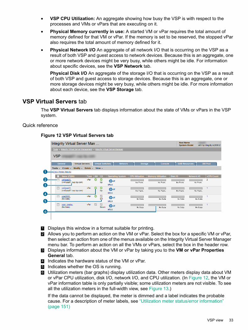
• VSP CPU Utilization: An aggregate showing how busy the VSP is with respect to theprocesses and VMs or vPars that are executing on it.
• Physical Memory currently in use: A started VM or vPar requires the total amount ofmemory defined for that VM or vPar. If the memory is set to be reserved, the stopped vParalso requires the total amount of memory defined for it.
• Physical Network I/O An aggregate of all network I/O that is occurring on the VSP as aresult of both VSP and guest access to network devices. Because this is an aggregate, oneor more network devices might be very busy, while others might be idle. For informationabout specific devices, see the VSP Network tab.Physical Disk I/O An aggregate of the storage I/O that is occurring on the VSP as a resultof both VSP and guest access to storage devices. Because this is an aggregate, one ormore storage devices might be very busy, while others might be idle. For more informationabout each device, see the VSP Storage tab.
VSP Virtual Servers tabThe VSP Virtual Servers tab displays information about the state of VMs or vPars in the VSPsystem.
Quick reference
Figure 12 VSP Virtual Servers tab
1 Displays this window in a format suitable for printing.2 Allows you to perform an action on the VM or vPar. Select the box for a specific VM or vPar,
then select an action from one of the menus available on the Integrity Virtual Server Managermenu bar. To perform an action on all the VMs or vPars, select the box in the header row.
3 Displays information about the VM or vPar by taking you to the VM or vPar PropertiesGeneral tab.
4 Indicates the hardware status of the VM or vPar.5 Indicates whether the OS is running.6 Utilization meters (bar graphs) display utilization data. Other meters display data about VM
or vPar CPU utilization, disk I/O, network I/O, and CPU utilization. (In Figure 12, the VM orvPar information table is only partially visible; some utilization meters are not visible. To seeall the utilization meters in the full-width view, see Figure 13.)If the data cannot be displayed, the meter is dimmed and a label indicates the probablecause. For a description of meter labels, see “Utilization meter status/error information”(page 151)
VSP view 33
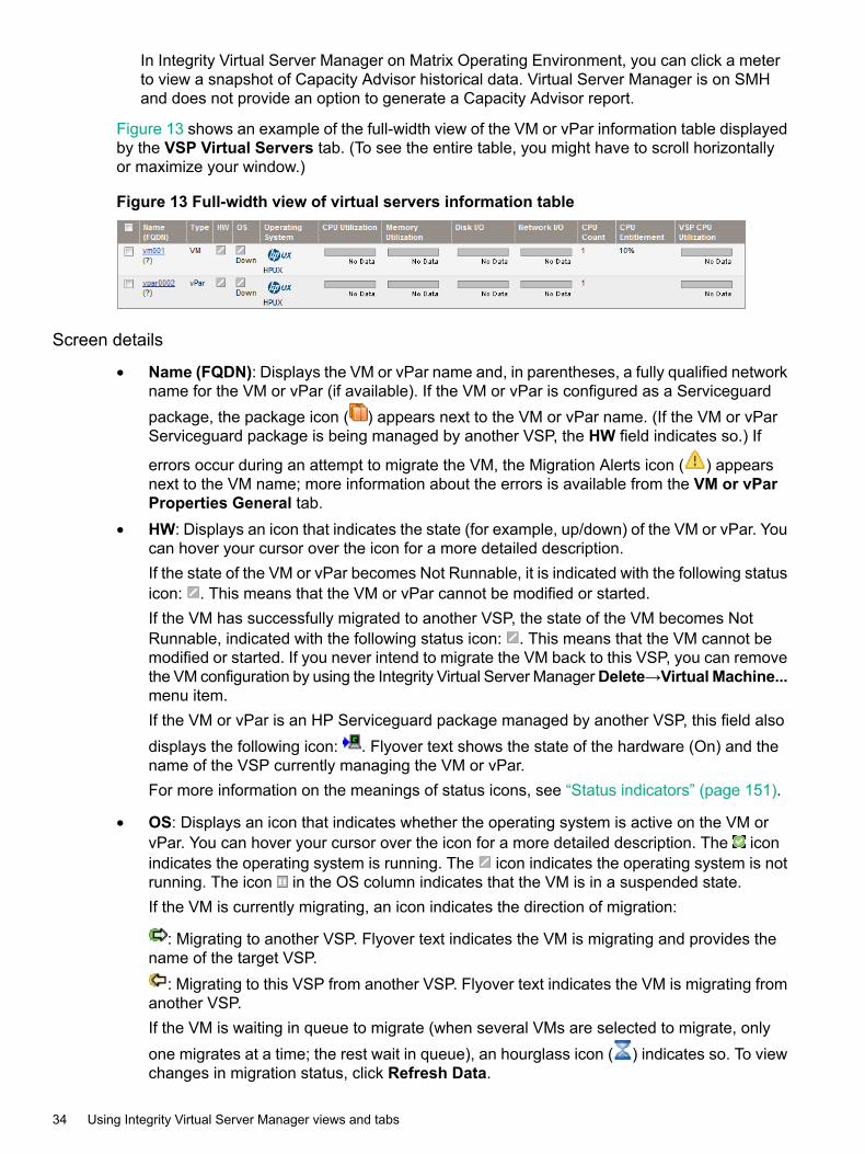
In Integrity Virtual Server Manager on Matrix Operating Environment, you can click a meterto view a snapshot of Capacity Advisor historical data. Virtual Server Manager is on SMHand does not provide an option to generate a Capacity Advisor report.
Figure 13 shows an example of the full-width view of the VM or vPar information table displayedby the VSP Virtual Servers tab. (To see the entire table, you might have to scroll horizontallyor maximize your window.)
Figure 13 Full-width view of virtual servers information table
Screen details
• Name (FQDN): Displays the VM or vPar name and, in parentheses, a fully qualified networkname for the VM or vPar (if available). If the VM or vPar is configured as a Serviceguardpackage, the package icon ( ) appears next to the VM or vPar name. (If the VM or vParServiceguard package is being managed by another VSP, the HW field indicates so.) If
errors occur during an attempt to migrate the VM, the Migration Alerts icon ( ) appearsnext to the VM name; more information about the errors is available from the VM or vParProperties General tab.
• HW: Displays an icon that indicates the state (for example, up/down) of the VM or vPar. Youcan hover your cursor over the icon for a more detailed description.If the state of the VM or vPar becomes Not Runnable, it is indicated with the following statusicon: . This means that the VM or vPar cannot be modified or started.If the VM has successfully migrated to another VSP, the state of the VM becomes NotRunnable, indicated with the following status icon: . This means that the VM cannot bemodified or started. If you never intend to migrate the VM back to this VSP, you can removethe VM configuration by using the Integrity Virtual Server ManagerDelete→Virtual Machine...menu item.If the VM or vPar is an HP Serviceguard package managed by another VSP, this field alsodisplays the following icon: . Flyover text shows the state of the hardware (On) and thename of the VSP currently managing the VM or vPar.For more information on the meanings of status icons, see “Status indicators” (page 151).
• OS: Displays an icon that indicates whether the operating system is active on the VM orvPar. You can hover your cursor over the icon for a more detailed description. The iconindicates the operating system is running. The icon indicates the operating system is notrunning. The icon in the OS column indicates that the VM is in a suspended state.If the VM is currently migrating, an icon indicates the direction of migration:
: Migrating to another VSP. Flyover text indicates the VM is migrating and provides thename of the target VSP.
: Migrating to this VSP from another VSP. Flyover text indicates the VM is migrating fromanother VSP.If the VM is waiting in queue to migrate (when several VMs are selected to migrate, onlyone migrates at a time; the rest wait in queue), an hourglass icon ( ) indicates so. To viewchanges in migration status, click Refresh Data.
34 Using Integrity Virtual Server Manager views and tabs

NOTE: Although only one VM migrates at a time, you might see indication of two machinesmigrating simultaneously to another VSP. The first migration has actually completed butIntegrity Virtual Server Manager has not yet received notification from the VM Provider.
For more information on the meanings of status icons, see “Status indicators” (page 151)
• Operating System: Displays the operating system type and version information for the VMor vPar.
• CPU Utilization: Displays how much of the virtual CPU assigned to the VM or vPar iscurrently being used.
NOTE: This and other utilization meters in this table display utilization data, if available.The utilization information is a 5-minute average that is calculated and updated on 5-minuteboundaries. If the utilization cannot be displayed, the utilization meter is dimmed and a labelindicates the probable cause. For a description of meter labels, see “Utilization meterstatus/error information” (page 151).Using Integrity Virtual Server Manager with Matrix Operating Environment, you can click autilization meter to view a snapshot of Capacity Advisor historical data; this feature is notprovided when using Integrity Virtual Server Manager from HP SMH. For an exampleutilization history screen and information about collecting and viewing utilization data, seeChapter 7 (page 133).
• Memory Utilization: Displays how much of the memory assigned to the VM or vPar iscurrently being used.
• Disk I/O: Displays storage I/O throughput measured for this VM or vPar.
• Network I/O: Displays network I/O throughput measured for this VM or vPar.
• CPU Count: Displays the number of CPUs in the VM or vPar.
• CPU Entitlement: Displays the percentage of CPU power guaranteed to the VM or vPar.This field is not displayed if the VM or vPar is being managed by gWLM.
• VSP CPU Utilization: Displays how many of the VSP's physical CPU resources are beingconsumed by this VM or vPar. This meter is not displayed if the VM or vPar is a Serviceguardpackage running on another VSP.
VSP Virtual Switches tabThe VSP Virtual Switches tab displays information about the virtual switches (vswitches) onthe VSP system.
Quick reference
Figure 14 VSP Virtual Switches tab
VSP view 35

1 Displays this window in a format suitable for printing.2 Allows you to perform an action on the virtual switches. Select the box for a vswitch, then
select a command from the menu to perform an action on the vswitch. To perform an actionon all the virtual switches, select the box in the header row.
3 Displays information about the virtual switch by taking you to the Vswitch Properties Generaltab.
4 Indicates whether the physical backing device supports Accelerated Virtual Input/Output(AVIO).
Screen details
• Virtual Switch Name: lists the names of the virtual switches.
• Status : shows whether the virtual switch is up (operational) or down (inoperational).
• Type: shows whether the corresponding virtual switch is a shared or dedicated vswitch.
• Supports AVIO: shows whether the corresponding backing device supports AcceleratedVirtual Input/Output (AVIO). AVIO is supported on HP Integrity VM Version 3.5 or later. Foreach VM or vPar containing an AVIO device, the VSP OS and the guest OS must supportAVIO. With HP Integrity VM, AVIO requires a virtual switch that has a physical networkdevice as the backing device (local virtual switches such as localnet are not supported). Inaddition, the physical NIC that backs the virtual switch must have an AVIO-compatible driver.For more information about AVIO requirements, see the HP Integrity VM documentation atthe following website (click on the HP Matrix Operating Environment for HP-UX tab):http://www.hpe.com/info/matrixoe/docs
• Used by: shows the VMs or vPars that are using the virtual switch. Position your cursor overthe information icon to view a list of the VMs or vPars that are connected to the virtual switch.
VSP Network tabThe VSP Network tab shows the mapping from virtual network interfaces in the VMs or vParsto the physical network interface cards (also called adapters) in the VSP system.
36 Using Integrity Virtual Server Manager views and tabs

Quick reference
Figure 15 VSP Network tab
1 Displays this window in a format suitable for printing.2 Displays detailed information about the VM or vPar by taking you to the VM or vPar
Properties General tab.3 Allows you to perform an action on the VM or vPar or I/O device. Select the box, then select
an action from one of the menus available on the Integrity Virtual Server Manager menu bar.4 Limits the display to only those network devices associated with the selected object (in this
instance, the devices associated with VM or vPar) and the objects directly connected to it.All other devices are not displayed. To return to the original view, click the Show All linkvisible beneath the Virtual Server Manager menu bar on the focused page.
5 Indicates by color coding that matching components are related.6 Utilization meters (bar graphs) provide data as a 5-minute average that is calculated and
updated on 5-minute boundaries. If data cannot be displayed, the meter is dimmed and alabel indicates the probable cause. For a description of meter labels, see “Utilization meterstatus/error information” (page 151).Utilization history links are not provided when using Virtual Server Manager through HPSMH.
VSP view 37
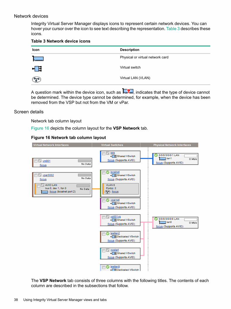
Network devicesIntegrity Virtual Server Manager displays icons to represent certain network devices. You canhover your cursor over the icon to see text describing the representation. Table 3 describes theseicons.
Table 3 Network device icons
DescriptionIcon
Physical or virtual network card
Virtual switch
Virtual LAN (VLAN)
A question mark within the device icon, such as , indicates that the type of device cannotbe determined. The device type cannot be determined, for example, when the device has beenremoved from the VSP but not from the VM or vPar.
Screen details
Network tab column layout
Figure 16 depicts the column layout for the VSP Network tab.
Figure 16 Network tab column layout
The VSP Network tab consists of three columns with the following titles. The contents of eachcolumn are described in the subsections that follow.
38 Using Integrity Virtual Server Manager views and tabs

Virtual Network Interfaces column contents
This column displays the virtual network interfaces in the VMs or vPars. The virtual networkinterfaces are grouped by VM or vPar. Each major box grouping in the column represents a VMor vPar.
Figure 17 Virtual Network Interfaces column
Referring to Figure 17, note the following:
• The icons next to the name of the VM or vPar and next to the network interface devicesshow the status of the system or interface. A question mark (?) means no information isavailable.
• Clicking the name of the VM or vPar (for example, vpar001) displays general informationabout the VM or vPar.
• Clicking the box near the VM or vPar name allows you to perform operations on the VM orvPar by using one of the menus available from the Integrity Virtual Server Manager menubar. Clicking the box next to the device label allows you to perform operations on the device(for example, removing the device).
• The bar graphs indicate network throughput, if available.
• If the VM or vPar is running and can be contacted by using WBEM, the network interfacesare shown (for example, vs1); otherwise, a portion of the hardware path (bus, device, andfunction) is shown.
• If the virtual network interface is defined to use Accelerated Virtual Input/Output (AVIO), thelabel AVIO appears with the network interface designation, such as AVIO LAN or AVIO lan0(the latter for a specific guest network interface designation). If the virtual network interfaceis not defined to use AVIO, the network interface designation does not include the AVIOlabel.
• The Focus link limits the display to a specific VM or vPar or interface and the objectsconnected to it. All other devices are not displayed. If you use this link to focus on only aspecific VM or vPar or interface, you can return to see all the VMs or vPars or networkinterfaces by using the Show All link visible on the focus page.
Virtual Switches column contents
This column displays details about each virtual switch. Each major box grouping represents avirtual switch.
VSP view 39

Figure 18 Virtual Switches column
Referring to Figure 18, note the following:• The icon next to the name of the virtual switch shows whether the virtual switch is operational.
• Clicking the box near the virtual switch name allows you to perform operations on the virtualswitch by using one of the menus available from the Integrity Virtual Server Manager menubar.
• Clicking the virtual switch name displays general information about the virtual switch.
• The icon and label below the virtual switch name indicates whether the corresponding virtualswitch is shared or dedicated.
• If the physical network interface that backs the virtual switch can support AVIO, the labelSupports AVIO appears next to the Focus link. The Focus link shows only that specificvirtual switch and anything connected to it. If use this link to focus on a specific virtual switch,you can return to displaying all the virtual switches by using the Show All link visible on thefocus page.
A virtual LAN (VLAN) is depicted as shown in Figure 19:
40 Using Integrity Virtual Server Manager views and tabs
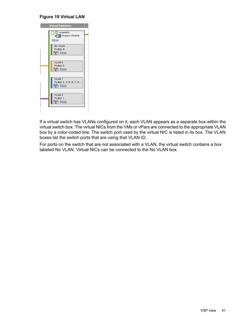
Figure 19 Virtual LAN
If a virtual switch has VLANs configured on it, each VLAN appears as a separate box within thevirtual switch box. The virtual NICs from the VMs or vPars are connected to the appropriate VLANbox by a color-coded line. The switch port used by the virtual NIC is listed in its box. The VLANboxes list the switch ports that are using that VLAN ID.For ports on the switch that are not associated with a VLAN, the virtual switch contains a boxlabeled No VLAN. Virtual NICs can be connected to the No VLAN box.
VSP view 41
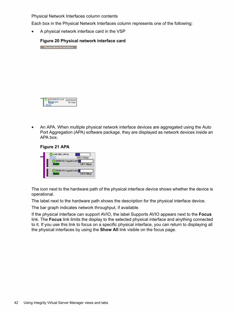
Physical Network Interfaces column contents
Each box in the Physical Network Interfaces column represents one of the following:
• A physical network interface card in the VSP
Figure 20 Physical network interface card
• An APA. When multiple physical network interface devices are aggregated using the AutoPort Aggregation (APA) software package, they are displayed as network devices inside anAPA box.
Figure 21 APA
The icon next to the hardware path of the physical interface device shows whether the device isoperational.The label next to the hardware path shows the description for the physical interface device.The bar graph indicates network throughput, if available.If the physical interface can support AVIO, the label Supports AVIO appears next to the Focuslink. The Focus link limits the display to the selected physical interface and anything connectedto it. If you use this link to focus on a specific physical interface, you can return to displaying allthe physical interfaces by using the Show All link visible on the focus page.
42 Using Integrity Virtual Server Manager views and tabs

Colors
The connections are color coded to help you identify interconnected elements.
NOTE: The actual colors shown do not imply any specific meaning. The colors are providedto help you understand the connections from virtual to physical devices.
Focus links
Clicking one of these links simplifies the display by showing only the item that was selected andthe elements that are directly attached to it.• Focusing on a VM or vPar shows the network interfaces on the VM or vPar, the virtual
switches that they are connected to, and the physical network interface devices connectedto the virtual switches.
• Focusing on a LAN in a VM or vPar shows only the devices and VMs or vPars connectedto the LAN.
• Focusing on a virtual network shows all of the virtual switches and all of the network interfacedevices connected to it.
• Focusing on a virtual switch shows only the devices and VMs or vPars connected to thevswitch.
• Focusing on a physical network interface device shows the virtual switches connected tothe physical interface device and all the virtual network interfaces connected to them.
• Focusing on an APA shows the shared virtual switches connected to it, and all the virtualnetwork interfaces connected to them.
• In a focused view, the presence of additional devices or connections are shown either asan ellipsis, or as a solid line becoming a dotted line.
• To view all the virtual network interfaces again, click the Show All link.
Dotted lines
The vertical dotted line indicates the boundary between the virtual and physical devices.
Bar graphs
The bar graphs are utilization meters that indicate the current IO throughput of a device or interfacedevice. When using Integrity Virtual Server Manager with Matrix Operating Environment forHP-UX, some bar graphs are selectable and bring up a view of the historical data related to thegraph.
VSP view 43

Status icons
These indicate whether an item is operational. Position the cursor over the icon to view a textualdescription. For more information about status icons, see “Status indicators” (page 151).
VSP Storage tabThe VSP Storage tab shows the mappings from the virtual storage devices in the VMs or vParsto the physical storage devices in the VSP system.
Quick reference
Figure 22 VSP Storage tab
1 Displays this window in a format suitable for printing.2 With the Show physical VSP bus adapters check box selected (as in this example), the
view includes the complete storage bus structure, VSP bus adapters, and multipath storageconfigurations. This view may take longer to render and can be more challenging fordiscerning the associations between VMs or vPars and devices, especially when manymultipath storage devices exist on the VSP. By default (the check box being unselected),the view is simpler, showing only the specific storage devices that are being used as backingdevices. For a multipath device, the simple view shows only the device special file (DSF)path, as specified when the virtual storage device was created. In contrast, the complexview displays all DSF versions of the same device, including the persistent DSF. The complexview is identical to the view displayed by the VSP Storage tab in earlier versions of VirtualServer Manager.When you navigate to another Integrity Virtual Server Manager view and return to this viewagain, the Show physical VSP bus adapters check box retains its state. In other words, if
44 Using Integrity Virtual Server Manager views and tabs
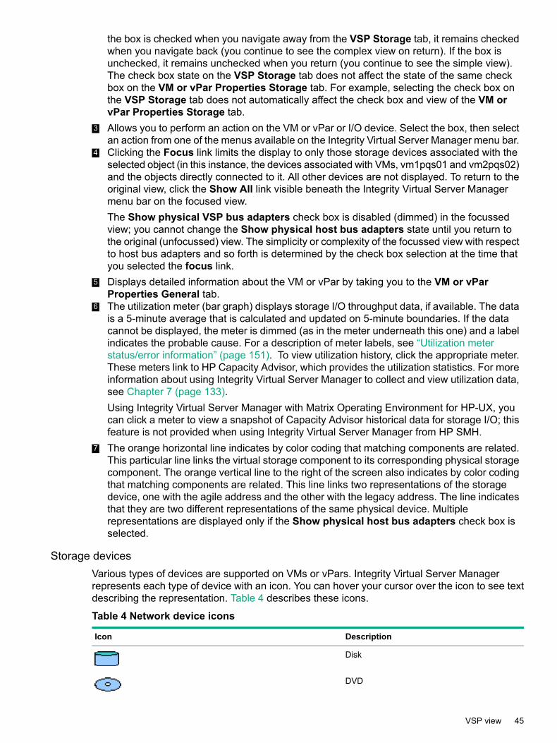
the box is checked when you navigate away from the VSP Storage tab, it remains checkedwhen you navigate back (you continue to see the complex view on return). If the box isunchecked, it remains unchecked when you return (you continue to see the simple view).The check box state on the VSP Storage tab does not affect the state of the same checkbox on the VM or vPar Properties Storage tab. For example, selecting the check box onthe VSP Storage tab does not automatically affect the check box and view of the VM orvPar Properties Storage tab.
3 Allows you to perform an action on the VM or vPar or I/O device. Select the box, then selectan action from one of the menus available on the Integrity Virtual Server Manager menu bar.
4 Clicking the Focus link limits the display to only those storage devices associated with theselected object (in this instance, the devices associated with VMs, vm1pqs01 and vm2pqs02)and the objects directly connected to it. All other devices are not displayed. To return to theoriginal view, click the Show All link visible beneath the Integrity Virtual Server Managermenu bar on the focused view.The Show physical VSP bus adapters check box is disabled (dimmed) in the focussedview; you cannot change the Show physical host bus adapters state until you return tothe original (unfocussed) view. The simplicity or complexity of the focussed view with respectto host bus adapters and so forth is determined by the check box selection at the time thatyou selected the focus link.
5 Displays detailed information about the VM or vPar by taking you to the VM or vParProperties General tab.
6 The utilization meter (bar graph) displays storage I/O throughput data, if available. The datais a 5-minute average that is calculated and updated on 5-minute boundaries. If the datacannot be displayed, the meter is dimmed (as in the meter underneath this one) and a labelindicates the probable cause. For a description of meter labels, see “Utilization meterstatus/error information” (page 151). To view utilization history, click the appropriate meter.These meters link to HP Capacity Advisor, which provides the utilization statistics. For moreinformation about using Integrity Virtual Server Manager to collect and view utilization data,see Chapter 7 (page 133).Using Integrity Virtual Server Manager with Matrix Operating Environment for HP-UX, youcan click a meter to view a snapshot of Capacity Advisor historical data for storage I/O; thisfeature is not provided when using Integrity Virtual Server Manager from HP SMH.
7 The orange horizontal line indicates by color coding that matching components are related.This particular line links the virtual storage component to its corresponding physical storagecomponent. The orange vertical line to the right of the screen also indicates by color codingthat matching components are related. This line links two representations of the storagedevice, one with the agile address and the other with the legacy address. The line indicatesthat they are two different representations of the same physical device. Multiplerepresentations are displayed only if the Show physical host bus adapters check box isselected.
Storage devicesVarious types of devices are supported on VMs or vPars. Integrity Virtual Server Managerrepresents each type of device with an icon. You can hover your cursor over the icon to see textdescribing the representation. Table 4 describes these icons.
Table 4 Network device icons
DescriptionIcon
Disk
DVD
VSP view 45
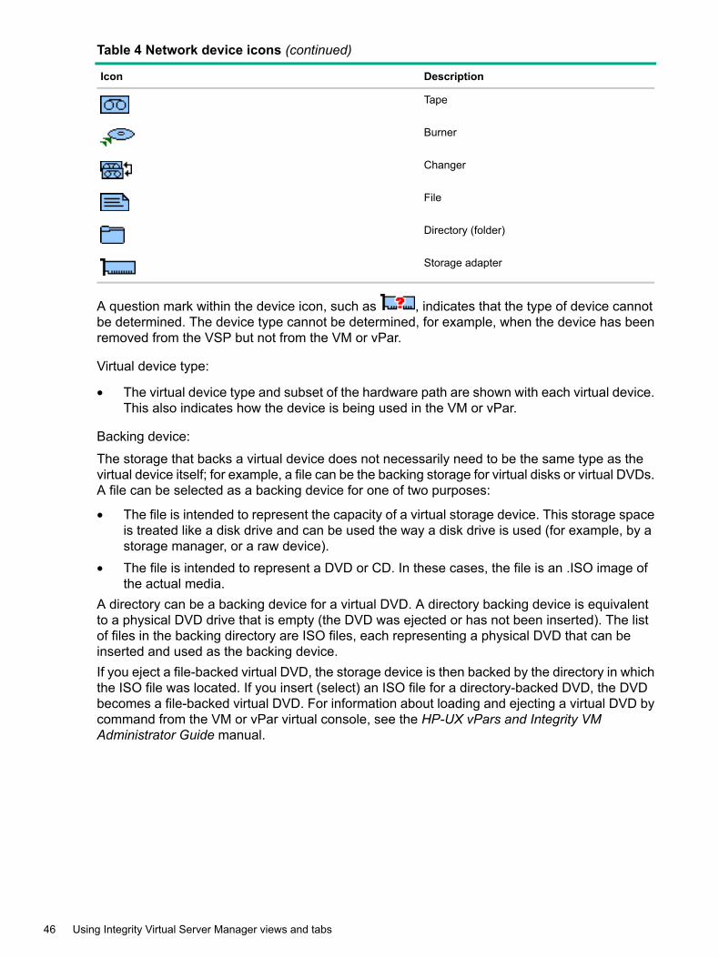
Table 4 Network device icons (continued)
DescriptionIcon
Tape
Burner
Changer
File
Directory (folder)
Storage adapter
A question mark within the device icon, such as , indicates that the type of device cannotbe determined. The device type cannot be determined, for example, when the device has beenremoved from the VSP but not from the VM or vPar.
Virtual device type:
• The virtual device type and subset of the hardware path are shown with each virtual device.This also indicates how the device is being used in the VM or vPar.
Backing device:
The storage that backs a virtual device does not necessarily need to be the same type as thevirtual device itself; for example, a file can be the backing storage for virtual disks or virtual DVDs.A file can be selected as a backing device for one of two purposes:
• The file is intended to represent the capacity of a virtual storage device. This storage spaceis treated like a disk drive and can be used the way a disk drive is used (for example, by astorage manager, or a raw device).
• The file is intended to represent a DVD or CD. In these cases, the file is an .ISO image ofthe actual media.
A directory can be a backing device for a virtual DVD. A directory backing device is equivalentto a physical DVD drive that is empty (the DVD was ejected or has not been inserted). The listof files in the backing directory are ISO files, each representing a physical DVD that can beinserted and used as the backing device.If you eject a file-backed virtual DVD, the storage device is then backed by the directory in whichthe ISO file was located. If you insert (select) an ISO file for a directory-backed DVD, the DVDbecomes a file-backed virtual DVD. For information about loading and ejecting a virtual DVD bycommand from the VM or vPar virtual console, see the HP-UX vPars and Integrity VMAdministrator Guide manual.
46 Using Integrity Virtual Server Manager views and tabs

NOTE: If you use Integrity Virtual Server Manager to manage a VSP running Integrity VMVersion 3.5 or earlier, Integrity Virtual Server Manager does not fully support virtual device specialfiles located in /hpap (introduced in HP StorageWorks Secure Path software Version 3.0F SP2)as backing devices for virtual storage. If a virtual storage device using an /hpap device specialfile already exists on a VM or vPar managed by Integrity Virtual Server Manager, Integrity VirtualServer Manager displays it on the VSP Storage and VM or vPar Properties Storage tabs asan unknown device (using the question mark icon, ). Integrity Virtual Server Manager displaysthe correct device special file name (for example, /hpap/rdsk/hpap1) but the box representingthis device is not connected to the boxes that represent the physical storage devices associatedwith that virtual device special file. In general, Integrity Virtual Server Manager correctly displaysonly those device special files located in /dev.
Screen details
Storage tab column layout
Figure 23 depicts the column layout for the VSP Storage tab.
Figure 23 Storage tab column layout
The VSP Storage tab consists of three columns with the following titles. The contents of eachcolumn are described in the subsections that follow.
Virtual Storage column contents
As shown in Figure 24, this column displays the virtual storage devices in the VMs or vPars. Thevirtual storage devices are grouped by VM or vPar. Each major box grouping in the columnrepresents a VM or vPar.
Figure 24 Virtual Storage column
Referring to Figure 24, note the following:
• The icon next to the name of the VM or vPar shows operational status of the VM or vPar. Aquestion mark (?) means no information is available.
• Clicking the name of the VM or vPar (for example, vse02v4) displays general informationabout the VM or vPar.
VSP view 47
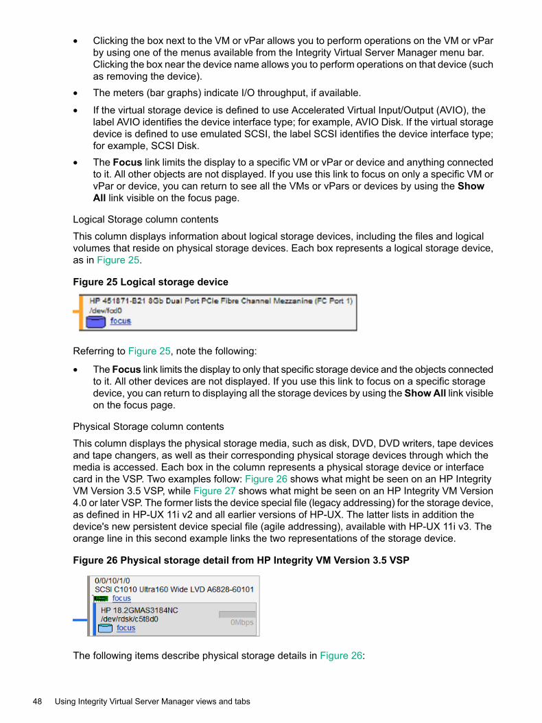
• Clicking the box next to the VM or vPar allows you to perform operations on the VM or vParby using one of the menus available from the Integrity Virtual Server Manager menu bar.Clicking the box near the device name allows you to perform operations on that device (suchas removing the device).
• The meters (bar graphs) indicate I/O throughput, if available.
• If the virtual storage device is defined to use Accelerated Virtual Input/Output (AVIO), thelabel AVIO identifies the device interface type; for example, AVIO Disk. If the virtual storagedevice is defined to use emulated SCSI, the label SCSI identifies the device interface type;for example, SCSI Disk.
• The Focus link limits the display to a specific VM or vPar or device and anything connectedto it. All other objects are not displayed. If you use this link to focus on only a specific VM orvPar or device, you can return to see all the VMs or vPars or devices by using the ShowAll link visible on the focus page.
Logical Storage column contents
This column displays information about logical storage devices, including the files and logicalvolumes that reside on physical storage devices. Each box represents a logical storage device,as in Figure 25.
Figure 25 Logical storage device
Referring to Figure 25, note the following:
• The Focus link limits the display to only that specific storage device and the objects connectedto it. All other devices are not displayed. If you use this link to focus on a specific storagedevice, you can return to displaying all the storage devices by using the ShowAll link visibleon the focus page.
Physical Storage column contents
This column displays the physical storage media, such as disk, DVD, DVD writers, tape devicesand tape changers, as well as their corresponding physical storage devices through which themedia is accessed. Each box in the column represents a physical storage device or interfacecard in the VSP. Two examples follow: Figure 26 shows what might be seen on an HP IntegrityVM Version 3.5 VSP, while Figure 27 shows what might be seen on an HP Integrity VM Version4.0 or later VSP. The former lists the device special file (legacy addressing) for the storage device,as defined in HP-UX 11i v2 and all earlier versions of HP-UX. The latter lists in addition thedevice's new persistent device special file (agile addressing), available with HP-UX 11i v3. Theorange line in this second example links the two representations of the storage device.
Figure 26 Physical storage detail from HP Integrity VM Version 3.5 VSP
The following items describe physical storage details in Figure 26:
48 Using Integrity Virtual Server Manager views and tabs

• The first line at the top includes the hardware path for the adapter (also referred to as theVSP bus adapter or HBA).
• The line below the hardware path (here, beginning with SCSI) describes the adapter.
• The first line in the gray box describes the storage device.
• The next line in the gray box (/dev/rdsk/c5t8d0) displays the device file path (devicespecial file) for the storage device, using the legacy addressing scheme.
• The bar graph is an I/O utilization meter that registers throughput. In this example, the meteris grayed out, indicating that the data is not available.
• Clicking a Focus link limits the display to the selected device and those objects connectedto it. All other devices are not shown. If you use this link to focus on a specific adapter ordevice, you can return to the original view displaying all the storage interface cards anddevices by using the Show All link visible on the focus page.
Figure 27 Physical storage detail from HP Integrity VM Version 4.0 or later VSP
The following items describe physical storage details in Figure 27:• The box on the top is the storage device representation with the persistent device special
file (agile addressing). The first line describes the storage device (HP 300 GST3300007LC).The next line below that (/dev/rdsk/disk3) displays the persistent device special file(DSF) path for the storage device. The path is persistent with respect to changes in theaccess path or host bus adapter, and can use multiple paths through a single device filename. This enables Integrity Virtual Server Manager to display a single DSF for each deviceinstead of displaying a separate DSF for each path to a device with multiple paths (as donewhen devices are displayed using the legacy addressing scheme).
• The second, larger box shows the adapter information, where the first line displays thehardware address (0/1/1/0), and the next line describes the adapter (SCSI Ultra320).The gray box within this larger box is the storage device representation of the HP 300GST3300007LC, but with the legacy DSF path (/dev/rdsk/c2t1d0).The orange line on the right of the two boxes links the two representations of the storagedevice (one with the agile address and the other with the legacy address), indicating thatthey are two different representations of the same physical device.
VSP view 49

• The utilization meter (bar graph) is an I/O utilization meter that registers throughput. In thisexample, the meter is grayed out, indicating that the data is not available.
• Clicking a Focus link displays information about the specific physical storage adapter ordevice and anything connected to it. If you use this link to focus on a specific adapter ordevice, you can return to the original view displaying all the storage interface cards anddevices by using the Show All link visible on the focus page.
Colors
The connections are color coded to help identify interconnected elements.
NOTE: The actual colors shown do not imply any specific meaning. The colors are providedto help you understand the connections from virtual to physical devices.
Focus links
Clicking a Focus link simplifies the display by showing only the item that was clicked and theelements that are directly attached to it:• Focusing on a VM or vPar shows the virtual storage interfaces in the VM or vPar and all the
logical storage devices, physical interface cards, and devices that back them.• Focusing on a virtual storage interface is like focusing on a VM or vPar, except that only the
selected virtual storage interface and its connections are shown; all others are hidden.• Focusing on a logical storage device shows all of the virtual storage devices and all of the
physical storage interface cards and devices connected to it.• Focusing on a physical storage interface card shows only the physical devices attached to
the card, the logical storage devices connected to the physical device, and the virtual storagedevices connected to those logical storage devices.
• Focusing on a physical storage device shows only the logical and virtual devices using thatphysical storage. This might reduce the number of devices shown, depending on how manyvirtual devices and VMs or vPars are connected to the physical storage device.
• In a focused view, the presence of additional devices or connections is shown by either anellipsis, or a solid line becoming a dotted line.
• To view all the storage devices again, use the Show All link.
Dotted lines
The black vertical dotted line indicates the boundary between the virtual and physical devices.
50 Using Integrity Virtual Server Manager views and tabs
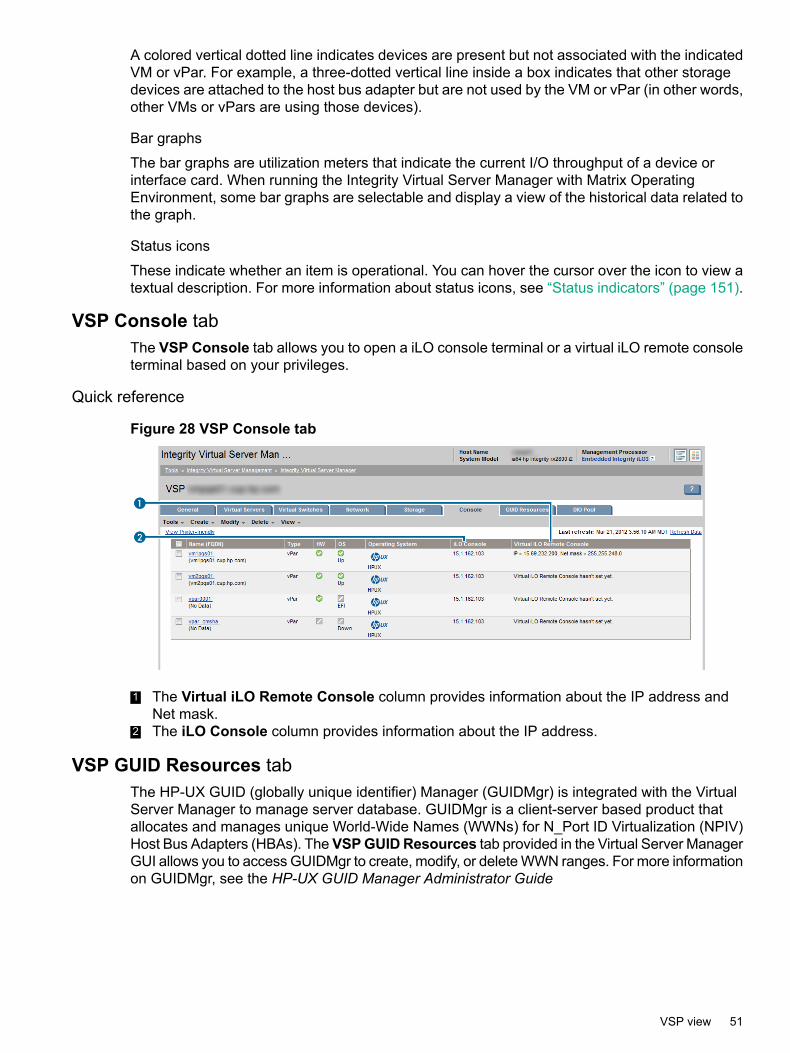
A colored vertical dotted line indicates devices are present but not associated with the indicatedVM or vPar. For example, a three-dotted vertical line inside a box indicates that other storagedevices are attached to the host bus adapter but are not used by the VM or vPar (in other words,other VMs or vPars are using those devices).
Bar graphs
The bar graphs are utilization meters that indicate the current I/O throughput of a device orinterface card. When running the Integrity Virtual Server Manager with Matrix OperatingEnvironment, some bar graphs are selectable and display a view of the historical data related tothe graph.
Status icons
These indicate whether an item is operational. You can hover the cursor over the icon to view atextual description. For more information about status icons, see “Status indicators” (page 151).
VSP Console tabThe VSP Console tab allows you to open a iLO console terminal or a virtual iLO remote consoleterminal based on your privileges.
Quick reference
Figure 28 VSP Console tab
1 The Virtual iLO Remote Console column provides information about the IP address andNet mask.
2 The iLO Console column provides information about the IP address.
VSP GUID Resources tabThe HP-UX GUID (globally unique identifier) Manager (GUIDMgr) is integrated with the VirtualServer Manager to manage server database. GUIDMgr is a client-server based product thatallocates and manages unique World-Wide Names (WWNs) for N_Port ID Virtualization (NPIV)Host Bus Adapters (HBAs). TheVSPGUIDResources tab provided in the Virtual Server ManagerGUI allows you to access GUIDMgr to create, modify, or delete WWN ranges. For more informationon GUIDMgr, see the HP-UX GUID Manager Administrator Guide
VSP view 51
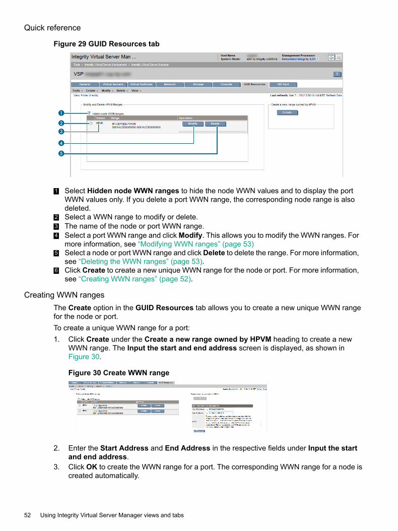
Quick reference
Figure 29 GUID Resources tab
1 Select Hidden node WWN ranges to hide the node WWN values and to display the portWWN values only. If you delete a port WWN range, the corresponding node range is alsodeleted.
2 Select a WWN range to modify or delete.3 The name of the node or port WWN range.4 Select a port WWN range and click Modify. This allows you to modify the WWN ranges. For
more information, see “Modifying WWN ranges” (page 53)5 Select a node or port WWN range and clickDelete to delete the range. For more information,
see “Deleting the WWN ranges” (page 53).6 Click Create to create a new unique WWN range for the node or port. For more information,
see “Creating WWN ranges” (page 52).
Creating WWN rangesThe Create option in the GUID Resources tab allows you to create a new unique WWN rangefor the node or port.To create a unique WWN range for a port:1. Click Create under the Create a new range owned by HPVM heading to create a new
WWN range. The Input the start and end address screen is displayed, as shown inFigure 30.
Figure 30 Create WWN range
2. Enter the Start Address and End Address in the respective fields under Input the startand end address.
3. Click OK to create the WWN range for a port. The corresponding WWN range for a node iscreated automatically.
52 Using Integrity Virtual Server Manager views and tabs

Modifying WWN rangesThe Modify option in the GUID Resources tab allows you to modify the unique WWN range forthe node or port.To modify the unique WWN range for a port:1. Select the port WWN range that you want to modify from the WWN ranges table and click
Modify. The Start Address and End Address fields are displayed, as shown in Figure 31.
Figure 31 Modify WWN ranges
2. Update the Start Address and End Address fields to specify the new WWN range.3. Click OK to update the WWN range for the selected port.
Deleting the WWN rangesThe Delete option in the GUID Resources tab allows you to delete the unique WWN range forthe node or port.To delete a WWN range for a port:1. Select the port WWN range that you want to delete and click Delete. A message prompts
you to confirm whether the range can be deleted, as displayed in Figure 32.
Figure 32 Delete WWN ranges
2. Select Yes to delete the selected range.
DIO Pool tabDirect Input Output (DIO) is an I/O architecture designed to provide a VM or a vPar with nearnative I/O functionality, manageability, and performance by giving a VM or a vPar direct accessto Host PCI Express (PCIe) functions, which may be physical or virtual. DIO is an additional I/Ooption and not a replacement for any current or planned HPVM I/O options. Figure 33 (page 54)shows the DIO Pool tab.
VSP view 53

Figure 33 DIO Pool tab
1 The SHOWDIO Table Option lists the options to view the DIOs in the host or HPVM. Whenyou select an option, its corresponding table is displayed. The following options are listed:• Show All DIO Resources displays both the host DIO tables and the HPVM DIO
table.• Show Host DIO Resources displays only the host DIO table. There are two host
DIO tables, one with IP and Vswitch and the other without IP and Vswitch.• Show HPVM DIO Resources displays only the HPVM DIO table.
2 Host DIO tables. One lists DIOs with IP and as PNIC for Vswitch. For more information aboutthe parameters, see “Column descriptions” (page 56).
3 The HPVM DIO table include parameters for the Integrity VM (vPar) DIO. For more informationabout the parameters, see “Column descriptions” (page 56)
Host DIO tableWhen you select the Show HOST DIO Resources option, the host DIO tables are displayed.There are two host DIO tables, one for DIOs with IP or as NPIC for Vswitch. The other onecontains the left DIOs.In the first table, the host DIO with IP or Vswitch has no check box. These host DIOs cannot beused to perform normal DIO operations, such as “Change Owner” or “Change Restricted Status”.This is because they are used by the host as sitelan or as PNIC for Vswitch. The second tablelists DIOs without IP or Vswitch. This table has a check box. You can use the DIOs in this tablefor normal DIO operations.The host DIO table lists the details of the DIOs owned by the host. The following DIO details aredisplayed:• H/W path
• LAN interface
• Status
• Assignment level
• Driver type
• A brief description of the DIO
• Whether the DIO is restricted
• Whether the DIO has IP and is used as PNIC for Vswitch
54 Using Integrity Virtual Server Manager views and tabs

The default setting is, the Change Restricted Status and Change Owner buttons are disabled.To enable them, you must select one or more DIOs. Figure 34 (page 55) shows the Host DIOtable .
Figure 34 Show HOST DIO Resources
You must select a DIO check box in the host DIO table to enable Change Restricted Statusand Change Owner.Click Change Restricted Status to change the restricted status of the DIO owned by host. Formore information, see “Changing the restricted status of host DIOs” (page 59).Click Change Owner to change the owner of the DIO to HPVM. For more information, see“Changing the owner of host DIOs to HPVM” (page 58).
HPVM DIO tableWhen you select Show HPVM DIO Resources, the HPVM DIO table is displayed.The HPVM DIO table lists the details of the DIOs owned by HPVM. The DIO details include theH/W path, assignment level, driver type, a brief description of the DIO, label of the DIO, and alsowhether the DIO is used by a guest VM or vPar. By default, the Change Label and ChangeOwner buttons are disabled. To enable them, you must select one or more DIOs in the table byselecting the check boxes. “HPVM DIO table” (page 55) shows the hpvm DIO .
VSP view 55
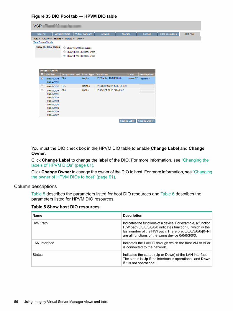
Figure 35 DIO Pool tab — HPVM DIO table
You must the DIO check box in the HPVM DIO table to enable Change Label and ChangeOwner.Click Change Label to change the label of the DIO. For more information, see “Changing thelabels of HPVM DIOs” (page 61).ClickChangeOwner to change the owner of the DIO to host. For more information, see “Changingthe owner of HPVM DIOs to host” (page 61).
Column descriptionsTable 5 describes the parameters listed for host DIO resources and Table 6 describes theparameters listed for HPVM DIO resources.nl
Table 5 Show host DIO resources
DescriptionName
Indicates the functions of a device. For example, a functionH/W path 0/0/0/3/0/0/0 indicates function 0, which is thelast number of the H/W path. Therefore, 0/0/0/3/0/0/[0–N]are all functions of the same device 0/0/0/3/0/0.
H/W Path
Indicates the LAN ID through which the host VM or vParis connected to the network.
LAN Interface
Indicates the status (Up or Down) of the LAN interface.The status is Up if the interface is operational, and Downif it is not operational.
Status
56 Using Integrity Virtual Server Manager views and tabs
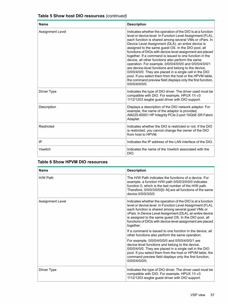
Table 5 Show host DIO resources (continued)
DescriptionName
Indicates whether the operation of the DIO is at a functionlevel or device level. In Function Level Assignment (FLA),each function is shared among several VMs or vPars. InDevice Level Assignment (DLA), an entire device isassigned to the same guest OS. In the DIO pool, allfunctions of DIOs with device-level assignment are placedtogether. If a command is issued to one function in thedevice, all other functions also perform the sameoperation. For example, 0/0/0/4/0/0/0 and 0/0/0/4/0/0/1are device-level functions and belong to the device,0/0/0/4/0/0. They are placed in a single cell in the DIOpool. If you select them from the host or the HPVM table,the command preview field displays only the first function,0/0/0/4/0/0/0.
Assignment Level
Indicates the type of DIO driver. The driver used must becompatible with DIO. For example, HPUX 11i v31112/1203 iexgbe guest driver with DIO support.
Driver Type
Displays a description of the DIO network adaptor. Forexample, the name of the adaptor is provided,AM225-60001 HP Integrity PCIe 2-port 10GbE-SR FabricAdapter.
Description
Indicates whether the DIO is restricted or not. If the DIOis restricted, you cannot change the owner of the DIOfrom host to HPVM.
Restricted
Indicates the IP address of the LAN interface of the DIO.IP
Indicates the name of the Vswitch associated with theDIO.
Vswitch
Table 6 Show HPVM DIO resources
DescriptionName
The H/W Path indicates the functions of a device. Forexample, a function H/W path 0/0/0/3/0/0/0 indicatesfunction 0, which is the last number of the H/W path.Therefore, 0/0/0/3/0/0/[0–N] are all functions of the samedevice 0/0/0/3/0/0.
H/W Path
Indicates whether the operation of the DIO is at a functionlevel or device level. In Function Level Assignment (FLA),each function is shared among several guest VMs orvPars. In Device Level Assignment (DLA), an entire deviceis assigned to the same guest OS. In the DIO pool, allfunctions of DIOs with device-level assignment are placedtogether.If a command is issued to one function in the device, allother functions also perform the same operation.For example, 0/0/0/4/0/0/0 and 0/0/0/4/0/0/1 aredevice-level functions and belong to the device,0/0/0/4/0/0. They are placed in a single cell in the DIOpool. If you select them from the host or HPVM table, thecommand preview field displays only the first function,0/0/0/4/0/0/0.
Assignment Level
Indicates the type of DIO driver. The driver used must becompatible with DIO. For example, HPUX 11i v31112/1203 iexgbe guest driver with DIO support.
Driver Type
VSP view 57
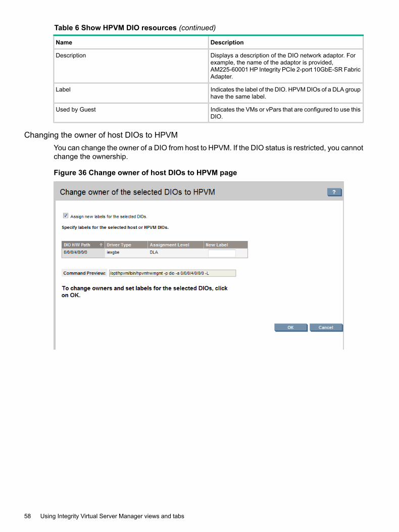
Table 6 Show HPVM DIO resources (continued)
DescriptionName
Displays a description of the DIO network adaptor. Forexample, the name of the adaptor is provided,AM225-60001 HP Integrity PCIe 2-port 10GbE-SR FabricAdapter.
Description
Indicates the label of the DIO. HPVM DIOs of a DLA grouphave the same label.
Label
Indicates the VMs or vPars that are configured to use thisDIO.
Used by Guest
Changing the owner of host DIOs to HPVMYou can change the owner of a DIO from host to HPVM. If the DIO status is restricted, you cannotchange the ownership.
Figure 36 Change owner of host DIOs to HPVM page
58 Using Integrity Virtual Server Manager views and tabs
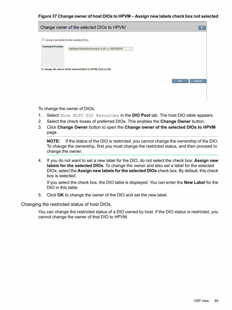
Figure 37 Change owner of host DIOs to HPVM – Assign new labels check box not selected
To change the owner of DIOs:1. Select Show HOST DIO Resources in the DIO Pool tab. The host DIO table appears.2. Select the check boxes of preferred DIOs. This enables the Change Owner button.3. Click Change Owner button to open the Change owner of the selected DIOs to HPVM
page.
NOTE: If the status of the DIO is restricted, you cannot change the ownership of the DIO.To change the ownership, first you must change the restricted status, and then proceed tochange the owner.
4. If you do not want to set a new label for the DIO, do not select the check box: Assign newlabels for the selected DIOs. To change the owner and also set a label for the selectedDIOs, select theAssign new labels for the selected DIOs check box. By default, this checkbox is selected.If you select the check box, the DIO table is displayed. You can enter the New Label for theDIO in this table.
5. Click OK to change the owner of the DIO and set the new label.
Changing the restricted status of host DIOsYou can change the restricted status of a DIO owned by host. If the DIO status is restricted, youcannot change the owner of that DIO to HPVM.
VSP view 59
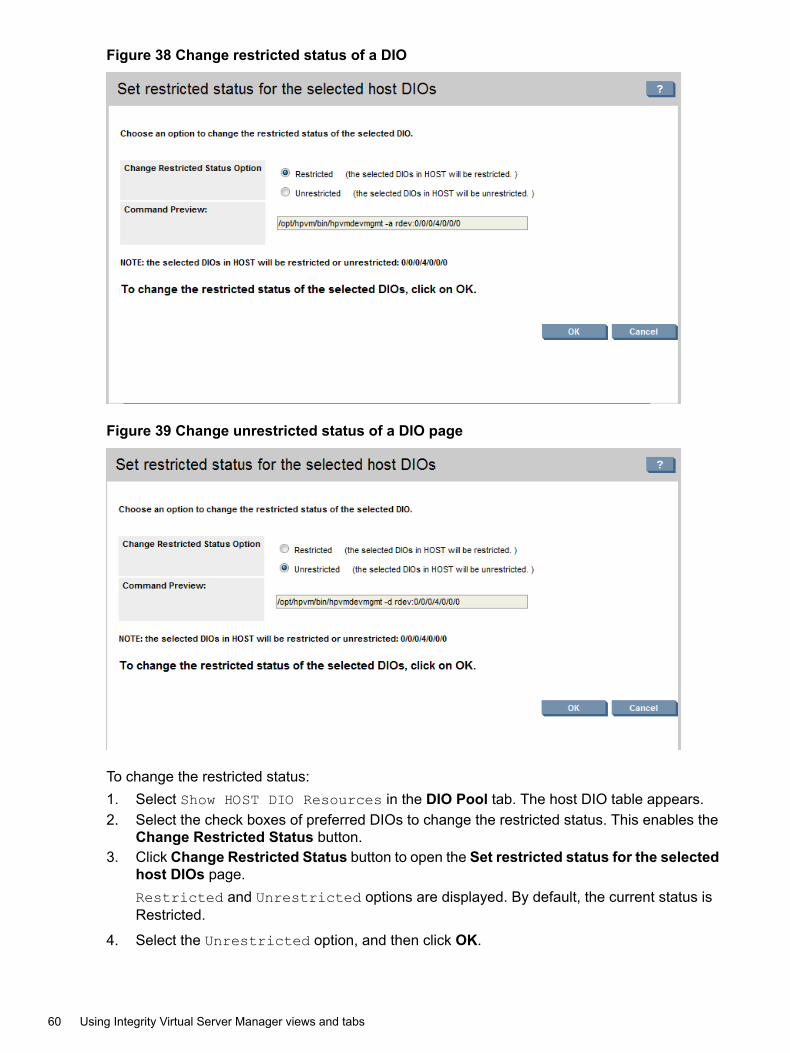
Figure 38 Change restricted status of a DIO
Figure 39 Change unrestricted status of a DIO page
To change the restricted status:1. Select Show HOST DIO Resources in the DIO Pool tab. The host DIO table appears.2. Select the check boxes of preferred DIOs to change the restricted status. This enables the
Change Restricted Status button.3. Click Change Restricted Status button to open the Set restricted status for the selected
host DIOs page.Restricted and Unrestricted options are displayed. By default, the current status isRestricted.
4. Select the Unrestricted option, and then click OK.
60 Using Integrity Virtual Server Manager views and tabs

Changing the owner of HPVM DIOs to hostYou can change the owner of DIOs from HPVM to host.
Figure 40 Change owner of HPVM DIOs to host
To change the owner of DIOs:1. Select Show HPVM DIO Resources in the DIO Pool tab. The HPVM DIO table appears.2. Select the check boxes of preferred DIOs to change the owner. This enables the Change
Owner button.3. Click Change Owner to open the Change owner of the selected DIOs to HOST page.
This page displays a note indicating that the owner of the selected DIOs will be changedfrom HPVM to the host.
4. Click OK to change the ownership to host.
Changing the labels of HPVM DIOsYou can set a new label or delete the existing label of HPVM DIOs.
Figure 41 Set label of HPVM DIO
VSP view 61
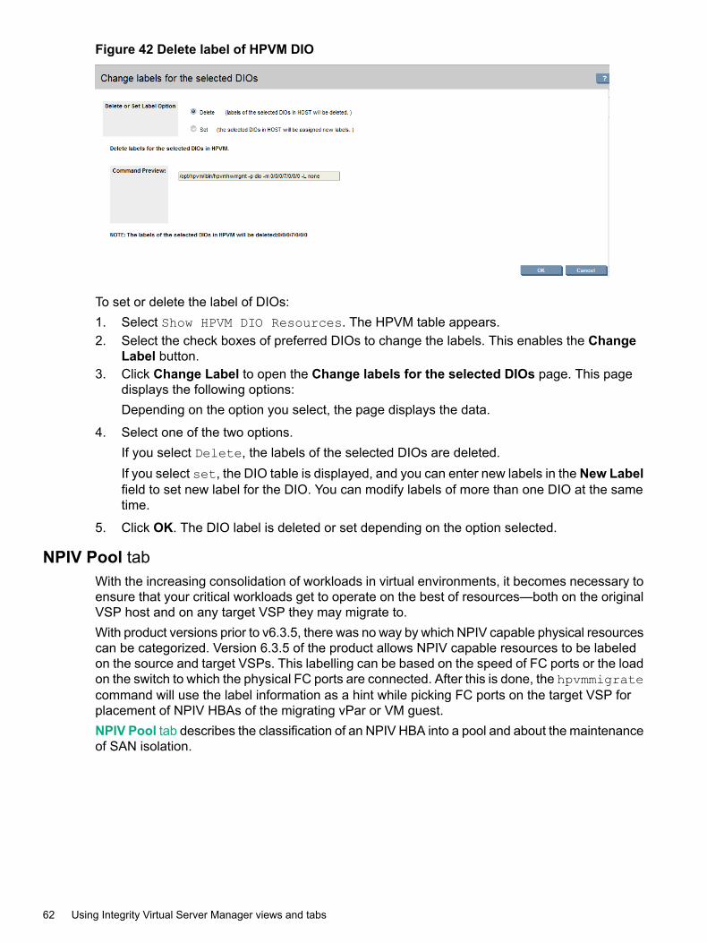
Figure 42 Delete label of HPVM DIO
To set or delete the label of DIOs:1. Select Show HPVM DIO Resources. The HPVM table appears.2. Select the check boxes of preferred DIOs to change the labels. This enables the Change
Label button.3. Click Change Label to open the Change labels for the selected DIOs page. This page
displays the following options:Depending on the option you select, the page displays the data.
4. Select one of the two options.If you select Delete, the labels of the selected DIOs are deleted.If you select set, the DIO table is displayed, and you can enter new labels in the New Labelfield to set new label for the DIO. You can modify labels of more than one DIO at the sametime.
5. Click OK. The DIO label is deleted or set depending on the option selected.
NPIV Pool tabWith the increasing consolidation of workloads in virtual environments, it becomes necessary toensure that your critical workloads get to operate on the best of resources—both on the originalVSP host and on any target VSP they may migrate to.With product versions prior to v6.3.5, there was no way by which NPIV capable physical resourcescan be categorized. Version 6.3.5 of the product allows NPIV capable resources to be labeledon the source and target VSPs. This labelling can be based on the speed of FC ports or the loadon the switch to which the physical FC ports are connected. After this is done, the hpvmmigratecommand will use the label information as a hint while picking FC ports on the target VSP forplacement of NPIV HBAs of the migrating vPar or VM guest.NPIV Pool tab describes the classification of an NPIV HBA into a pool and about the maintenanceof SAN isolation.
62 Using Integrity Virtual Server Manager views and tabs
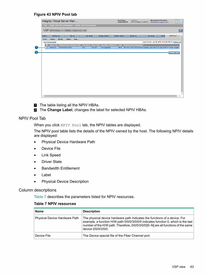
Figure 43 NPIV Pool tab
1 The table listing all the NPIV HBAs.2 The Change Label, changes the label for selected NPIV HBAs.
NPIV Pool TabWhen you click NPIV Pool tab, the NPIV tables are displayed.The NPIV pool table lists the details of the NPIV owned by the host. The following NPIV detailsare displayed:• Physical Device Hardware Path
• Device File
• Link Speed
• Driver State
• Bandwidth Entitlement
• Label
• Physical Device Description
Column descriptionsTable 7 describes the parameters listed for NPIV resources.nl
Table 7 NPIV resources
DescriptionName
The physical device hardware path indicates the functions of a device. Forexample, a function H/W path 0/0/0/3/0/0/0 indicates function 0, which is the lastnumber of the H/W path. Therefore, 0/0/0/3/0/0/[0–N] are all functions of the samedevice 0/0/0/3/0/0.
Physical Device Hardware Path
The Device special file of the Fiber Channel port.Device File
VSP view 63
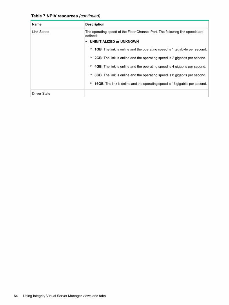
Table 7 NPIV resources (continued)
DescriptionName
The operating speed of the Fiber Channel Port. The following link speeds aredefined:
• UNINITIALIZED or UNKNOWN
◦ 1GB: The link is online and the operating speed is 1 gigabyte per second.
◦ 2GB: The link is online and the operating speed is 2 gigabits per second.
◦ 4GB: The link is online and the operating speed is 4 gigabits per second.
◦ 8GB: The link is online and the operating speed is 8 gigabits per second.
◦ 16GB: The link is online and the operating speed is 16 gigabits per second.
Link Speed
Driver State
64 Using Integrity Virtual Server Manager views and tabs
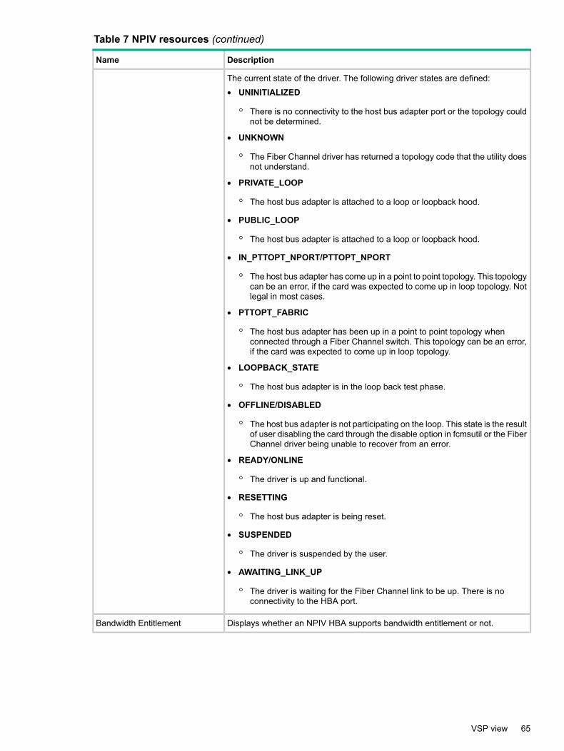
Table 7 NPIV resources (continued)
DescriptionName
The current state of the driver. The following driver states are defined:
• UNINITIALIZED
◦ There is no connectivity to the host bus adapter port or the topology couldnot be determined.
• UNKNOWN
◦ The Fiber Channel driver has returned a topology code that the utility doesnot understand.
• PRIVATE_LOOP
◦ The host bus adapter is attached to a loop or loopback hood.
• PUBLIC_LOOP
◦ The host bus adapter is attached to a loop or loopback hood.
• IN_PTTOPT_NPORT/PTTOPT_NPORT
◦ The host bus adapter has come up in a point to point topology. This topologycan be an error, if the card was expected to come up in loop topology. Notlegal in most cases.
• PTTOPT_FABRIC
◦ The host bus adapter has been up in a point to point topology whenconnected through a Fiber Channel switch. This topology can be an error,if the card was expected to come up in loop topology.
• LOOPBACK_STATE
◦ The host bus adapter is in the loop back test phase.
• OFFLINE/DISABLED
◦ The host bus adapter is not participating on the loop. This state is the resultof user disabling the card through the disable option in fcmsutil or the FiberChannel driver being unable to recover from an error.
• READY/ONLINE
◦ The driver is up and functional.
• RESETTING
◦ The host bus adapter is being reset.
• SUSPENDED
◦ The driver is suspended by the user.
• AWAITING_LINK_UP
◦ The driver is waiting for the Fiber Channel link to be up. There is noconnectivity to the HBA port.
Displays whether an NPIV HBA supports bandwidth entitlement or not.Bandwidth Entitlement
VSP view 65

Table 7 NPIV resources (continued)
DescriptionName
Displays the label associated with the Fiber Channel Port. The label can be basedon the speed of FC ports or the load on the switch to which the physical FC portsare connected and so on. The hpvmmigrate command will use the labelinformation as a hint while picking FC ports on the target VSP for placement ofNPIV HBAs of the migrating vPar or VM guest.
Label
Displays a description of the NPIV Fiber Channel adaptor. For example, the nameof the adaptor is provided, “HP 403619-B21 4Gb Dual Port PCIe Fiber ChannelMezzanine (FC Port 1)”.
Physical Device Description
Changing the labels of NPIV HBAsYou can set a new label or delete the existing label of NPIV HBAs.
Figure 44 Set label of NPIV HBA
Figure 45 Delete label of NPIV HBA
To set or delete the label of NPIV HBAs:
66 Using Integrity Virtual Server Manager views and tabs
1. Select the check boxes of preferred NPIV HBAs to change the labels. This enables theChange Label button.
2. Click Change Label to open the Change labels for the selected NPIV HBAs page.3. Select one of the two options.
If you select Delete, the labels of the selected NPIV HBAs are deleted.If you select Set, the NPIV HBA table is displayed, and you can enter new labels in the NewLabel field to set new label for the NPIV HBA. You can modify labels of more than one NPIVHBA at the same time.
4. Click OK. The NPIV HBA label is deleted or set depending on the option selected.
VM or vPar Properties viewYou can access the VM or vPar Properties view from any other Integrity Virtual Server Managerviews that include a link to a VM or vPar, such as the VSP General tab, the VSP Virtual Serverstab, or any Network or Storage tab. You can also access the VM or vPar Properties view byselecting View→VM or vPar Properties... (a VM or vPar must be selected in the current view).Figure 46 shows a portion of a typical VM or vPar Properties view. Tabs available from the vieware described in the text that follows. Subsequent sections describe each tab in more detail.
VM or vPar Properties view 67
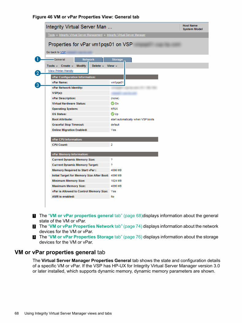
Figure 46 VM or vPar Properties View: General tab
1 The “VM or vPar properties general tab” (page 68)displays information about the generalstate of the VM or vPar.
2 The “VMor vPar Properties Network tab” (page 74) displays information about the networkdevices for the VM or vPar.
3 The “VM or vPar Properties Storage tab” (page 76) displays information about the storagedevices for the VM or vPar.
VM or vPar properties general tabThe Virtual Server Manager Properties General tab shows the state and configuration detailsof a specific VM or vPar. If the VSP has HP-UX for Integrity Virtual Server Manager version 3.0or later installed, which supports dynamic memory, dynamic memory parameters are shown.
68 Using Integrity Virtual Server Manager views and tabs

Quick reference
Figure 47 VM Properties General tab
VM or vPar Properties view 69
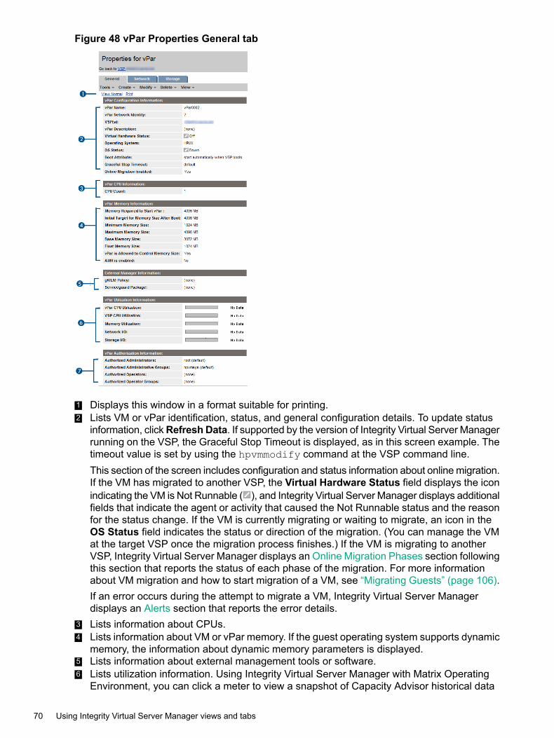
Figure 48 vPar Properties General tab
1 Displays this window in a format suitable for printing.2 Lists VM or vPar identification, status, and general configuration details. To update status
information, clickRefresh Data. If supported by the version of Integrity Virtual Server Managerrunning on the VSP, the Graceful Stop Timeout is displayed, as in this screen example. Thetimeout value is set by using the hpvmmodify command at the VSP command line.This section of the screen includes configuration and status information about online migration.If the VM has migrated to another VSP, the Virtual Hardware Status field displays the iconindicating the VM is Not Runnable ( ), and Integrity Virtual Server Manager displays additionalfields that indicate the agent or activity that caused the Not Runnable status and the reasonfor the status change. If the VM is currently migrating or waiting to migrate, an icon in theOS Status field indicates the status or direction of the migration. (You can manage the VMat the target VSP once the migration process finishes.) If the VM is migrating to anotherVSP, Integrity Virtual Server Manager displays an Online Migration Phases section followingthis section that reports the status of each phase of the migration. For more informationabout VM migration and how to start migration of a VM, see “Migrating Guests” (page 106).If an error occurs during the attempt to migrate a VM, Integrity Virtual Server Managerdisplays an Alerts section that reports the error details.
3 Lists information about CPUs.4 Lists information about VM or vPar memory. If the guest operating system supports dynamic
memory, the information about dynamic memory parameters is displayed.5 Lists information about external management tools or software.6 Lists utilization information. Using Integrity Virtual Server Manager with Matrix Operating
Environment, you can click a meter to view a snapshot of Capacity Advisor historical data
70 Using Integrity Virtual Server Manager views and tabs
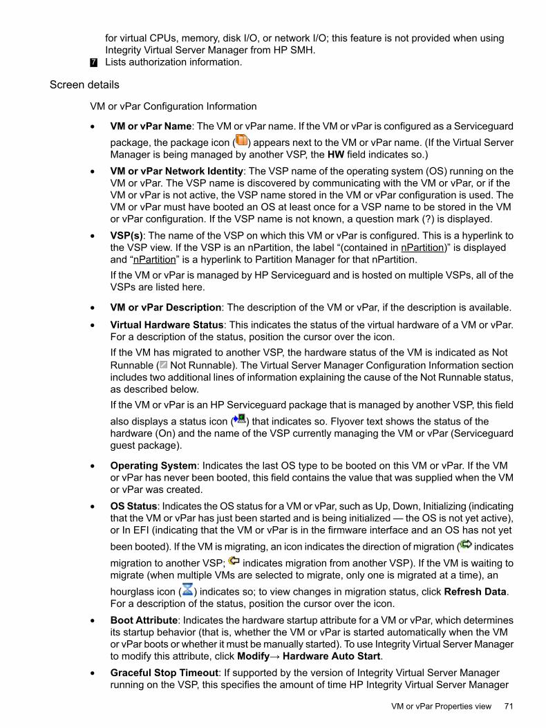
for virtual CPUs, memory, disk I/O, or network I/O; this feature is not provided when usingIntegrity Virtual Server Manager from HP SMH.
7 Lists authorization information.
Screen details
VM or vPar Configuration Information
• VM or vPar Name: The VM or vPar name. If the VM or vPar is configured as a Serviceguardpackage, the package icon ( ) appears next to the VM or vPar name. (If the Virtual ServerManager is being managed by another VSP, the HW field indicates so.)
• VM or vPar Network Identity: The VSP name of the operating system (OS) running on theVM or vPar. The VSP name is discovered by communicating with the VM or vPar, or if theVM or vPar is not active, the VSP name stored in the VM or vPar configuration is used. TheVM or vPar must have booted an OS at least once for a VSP name to be stored in the VMor vPar configuration. If the VSP name is not known, a question mark (?) is displayed.
• VSP(s): The name of the VSP on which this VM or vPar is configured. This is a hyperlink tothe VSP view. If the VSP is an nPartition, the label “(contained in nPartition)” is displayedand “nPartition” is a hyperlink to Partition Manager for that nPartition.If the VM or vPar is managed by HP Serviceguard and is hosted on multiple VSPs, all of theVSPs are listed here.
• VM or vPar Description: The description of the VM or vPar, if the description is available.
• Virtual Hardware Status: This indicates the status of the virtual hardware of a VM or vPar.For a description of the status, position the cursor over the icon.If the VM has migrated to another VSP, the hardware status of the VM is indicated as NotRunnable ( Not Runnable). The Virtual Server Manager Configuration Information sectionincludes two additional lines of information explaining the cause of the Not Runnable status,as described below.If the VM or vPar is an HP Serviceguard package that is managed by another VSP, this fieldalso displays a status icon ( ) that indicates so. Flyover text shows the status of thehardware (On) and the name of the VSP currently managing the VM or vPar (Serviceguardguest package).
• Operating System: Indicates the last OS type to be booted on this VM or vPar. If the VMor vPar has never been booted, this field contains the value that was supplied when the VMor vPar was created.
• OSStatus: Indicates the OS status for a VM or vPar, such as Up, Down, Initializing (indicatingthat the VM or vPar has just been started and is being initialized — the OS is not yet active),or In EFI (indicating that the VM or vPar is in the firmware interface and an OS has not yetbeen booted). If the VM is migrating, an icon indicates the direction of migration ( indicatesmigration to another VSP; indicates migration from another VSP). If the VM is waiting tomigrate (when multiple VMs are selected to migrate, only one is migrated at a time), anhourglass icon ( ) indicates so; to view changes in migration status, click Refresh Data.For a description of the status, position the cursor over the icon.
• Boot Attribute: Indicates the hardware startup attribute for a VM or vPar, which determinesits startup behavior (that is, whether the VM or vPar is started automatically when the VMor vPar boots or whether it must be manually started). To use Integrity Virtual Server Managerto modify this attribute, click Modify→ Hardware Auto Start.
• Graceful Stop Timeout: If supported by the version of Integrity Virtual Server Managerrunning on the VSP, this specifies the amount of time HP Integrity Virtual Server Manager
VM or vPar Properties view 71
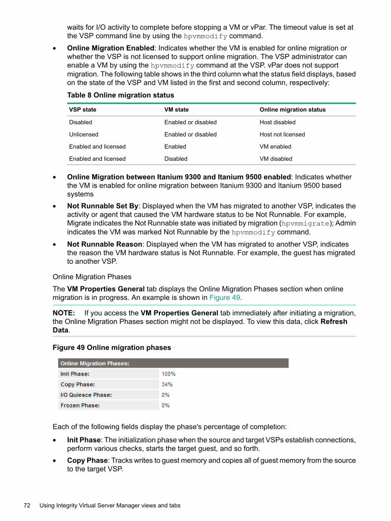
waits for I/O activity to complete before stopping a VM or vPar. The timeout value is set atthe VSP command line by using the hpvmmodify command.
• Online Migration Enabled: Indicates whether the VM is enabled for online migration orwhether the VSP is not licensed to support online migration. The VSP administrator canenable a VM by using the hpvmmodify command at the VSP. vPar does not supportmigration. The following table shows in the third column what the status field displays, basedon the state of the VSP and VM listed in the first and second column, respectively:
Table 8 Online migration status
Online migration statusVM stateVSP state
Host disabledEnabled or disabledDisabled
Host not licensedEnabled or disabledUnlicensed
VM enabledEnabledEnabled and licensed
VM disabledDisabledEnabled and licensed
• Online Migration between Itanium 9300 and Itanium 9500 enabled: Indicates whetherthe VM is enabled for online migration between Itanium 9300 and Itanium 9500 basedsystems
• Not Runnable Set By: Displayed when the VM has migrated to another VSP, indicates theactivity or agent that caused the VM hardware status to be Not Runnable. For example,Migrate indicates the Not Runnable state was initiated by migration (hpvmmigrate); Adminindicates the VM was marked Not Runnable by the hpvmmodify command.
• Not Runnable Reason: Displayed when the VM has migrated to another VSP, indicatesthe reason the VM hardware status is Not Runnable. For example, the guest has migratedto another VSP.
Online Migration Phases
The VM Properties General tab displays the Online Migration Phases section when onlinemigration is in progress. An example is shown in Figure 49.
NOTE: If you access the VM Properties General tab immediately after initiating a migration,the Online Migration Phases section might not be displayed. To view this data, click RefreshData.
Figure 49 Online migration phases
Each of the following fields display the phase's percentage of completion:
• Init Phase: The initialization phase when the source and target VSPs establish connections,perform various checks, starts the target guest, and so forth.
• Copy Phase: Tracks writes to guest memory and copies all of guest memory from the sourceto the target VSP.
72 Using Integrity Virtual Server Manager views and tabs

• I/O Quiesce Phase: Completes outstanding I/O and queues new I/O requests for the targetguest.
• Frozen Phase: Stops the virtual CPUs and copies modified memory and guest state to thetarget guest.
Alerts
The VM Properties General tab displays the Alerts section only when an error occurs during anattempt to migrate one or more VMs to another VSP. An example is shown in Figure 50.
Figure 50 Migration alerts
• Error: Displays errors pertaining to migration of VMs.
You can clear the alerts information by clicking the trash button ( ) on the right. This also
clears the Migration Alerts icon ( ) next to the VM name on the VSP Virtual Servers tab.For more information about migration and how to start the migration of a VM, see “MigratingGuests” (page 106).
VM or vPar CPU Information
• CPU Count: The number of virtual CPUs in the VM or vPar. To use Virtual Server Managerto modify the CPU count, click Modify→ VM or vPar CPU Count.
VM or vPar Memory Information
To use Virtual Server Manager to modify the following parameters, click Modify→Memory.
• Memory Required to Start VM or vPar: The amount of memory needed for the VM or vParto boot.
• Initial Target for Memory Size After Boot: The value to which Integrity Virtual ServerManager tries to change the VM or vPar memory immediately after it boots.
• MinimumMemory Size: The lowest value to which the VM or vPar can attempt to decreaseits memory while the OS is running.
• MaximumMemory Size: The highest value to which the VM or vPar can attempt to increaseits memory while the OS is running.
• Base Memory Size: The memory size value that you specify for a vPar. The base memorythat you specify is the kernel memory.
• Float Memory Size: The memory size value that you specify for a vPar. Float memory isan optional value.
NOTE: Base Memory Size and Float Memory Size fields are displayed only for vPars.
• VM or vPar is Allowed to Control Memory Size: Indicates whether the Allow dynamiccontrol of memory size from the VM or vPar is in effect. This control allows applications
VM or vPar Properties view 73
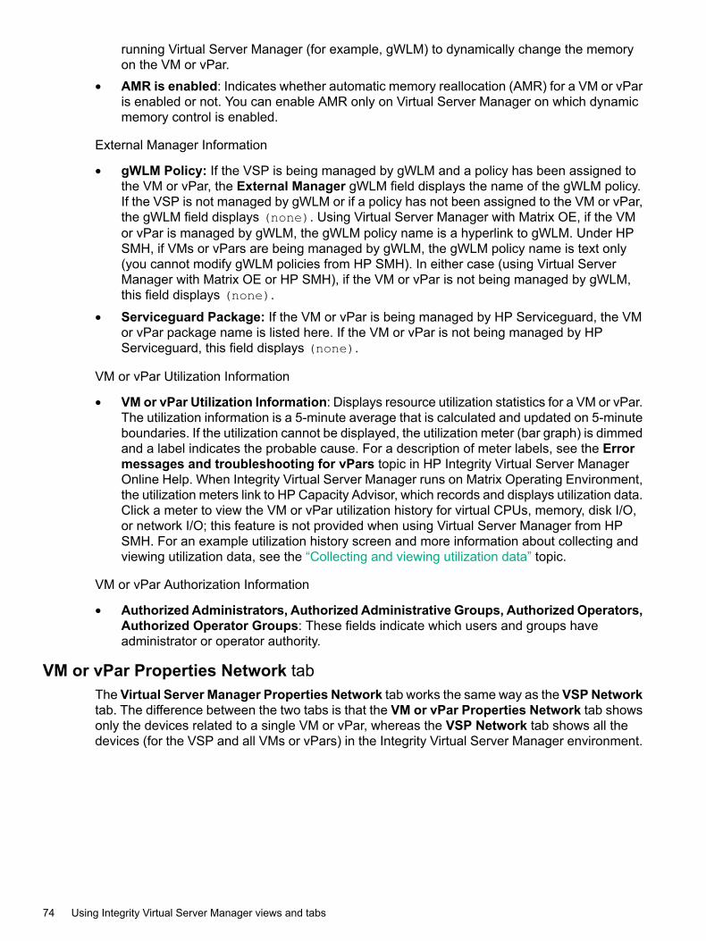
running Virtual Server Manager (for example, gWLM) to dynamically change the memoryon the VM or vPar.
• AMR is enabled: Indicates whether automatic memory reallocation (AMR) for a VM or vParis enabled or not. You can enable AMR only on Virtual Server Manager on which dynamicmemory control is enabled.
External Manager Information
• gWLM Policy: If the VSP is being managed by gWLM and a policy has been assigned tothe VM or vPar, the External Manager gWLM field displays the name of the gWLM policy.If the VSP is not managed by gWLM or if a policy has not been assigned to the VM or vPar,the gWLM field displays (none). Using Virtual Server Manager with Matrix OE, if the VMor vPar is managed by gWLM, the gWLM policy name is a hyperlink to gWLM. Under HPSMH, if VMs or vPars are being managed by gWLM, the gWLM policy name is text only(you cannot modify gWLM policies from HP SMH). In either case (using Virtual ServerManager with Matrix OE or HP SMH), if the VM or vPar is not being managed by gWLM,this field displays (none).
• Serviceguard Package: If the VM or vPar is being managed by HP Serviceguard, the VMor vPar package name is listed here. If the VM or vPar is not being managed by HPServiceguard, this field displays (none).
VM or vPar Utilization Information
• VM or vPar Utilization Information: Displays resource utilization statistics for a VM or vPar.The utilization information is a 5-minute average that is calculated and updated on 5-minuteboundaries. If the utilization cannot be displayed, the utilization meter (bar graph) is dimmedand a label indicates the probable cause. For a description of meter labels, see the Errormessages and troubleshooting for vPars topic in HP Integrity Virtual Server ManagerOnline Help. When Integrity Virtual Server Manager runs on Matrix Operating Environment,the utilization meters link to HP Capacity Advisor, which records and displays utilization data.Click a meter to view the VM or vPar utilization history for virtual CPUs, memory, disk I/O,or network I/O; this feature is not provided when using Virtual Server Manager from HPSMH. For an example utilization history screen and more information about collecting andviewing utilization data, see the “Collecting and viewing utilization data” topic.
VM or vPar Authorization Information
• Authorized Administrators, Authorized Administrative Groups, Authorized Operators,Authorized Operator Groups: These fields indicate which users and groups haveadministrator or operator authority.
VM or vPar Properties Network tabThe Virtual Server Manager Properties Network tab works the same way as the VSP Networktab. The difference between the two tabs is that the VM or vPar Properties Network tab showsonly the devices related to a single VM or vPar, whereas the VSP Network tab shows all thedevices (for the VSP and all VMs or vPars) in the Integrity Virtual Server Manager environment.
74 Using Integrity Virtual Server Manager views and tabs

Quick reference
Figure 51 VM or vPar Properties Network tab
1 Goes back to the previous view, in this case the Integrity Virtual Server Manager VSP view.When you access the Virtual Server Manager Properties view from another Integrity VirtualServer Manager view (such as the VSP view), the link returns you to that previous view. Ifyou had accessed the Virtual Server Manager Properties view directly from Matrix OEvisualization, the link returns you to Matrix OE visualization. In HP SMH, when you firstaccess this page from HP SMH, the link is not provided. The link appears whenever youmove from one Integrity Virtual Server Manager view to another (such as from VSP view toVirtual Server Manager Properties view, in which case the Go back to Integrity VirtualServer Manager: Manage Host link appears on the Virtual Server Manager Propertiesview).
2 Displays this window in a format suitable for printing.3 The utilization meter (bar graph) displays network I/O throughput data, if available. The data
is a 5-minute average that is calculated and updated on 5-minute boundaries. If the datacannot be displayed, the meter is dimmed as in this example, and a label indicates thepossible cause. For a description of meter labels, see the Error messages andtroubleshooting for vPars topic in HP Integrity Virtual Server Manager Online Help. UsingVirtual Server Manager with Matrix Operating Environment, you can click a meter to view asnapshot of Capacity Advisor historical data for network I/O; this feature is not providedwhen using Virtual Server Manager from HP SMH. For an example utilization history screenand more information about collecting and viewing utilization data, see the Collecting andviewing utilization data topic.
4 Displays the type of network interface such as emulated LAN (displayed as “LAN” ) orAccelerated Virtual Input/Output LAN (displayed as “AVIO LAN,” as in this instance).
5 Allows you to perform an action on the I/O device. Select the box, then select an action fromthe appropriate menu available on the Integrity Virtual Server Manager menu bar.
6 Limits the display to only those network devices associated with the selected object (in thisinstance, the device associated with port 1) and the objects directly connected to it. To returnto the original view, click the ShowAll link visible beneath the Integrity Virtual Server Managermenu bar on the focused page.
7 Color coding indicates that matching components are related.
Screen detailsFor more information about using and interpreting the items displayed in the Network tab, see“Screen details” (page 38).
VM or vPar Properties view 75
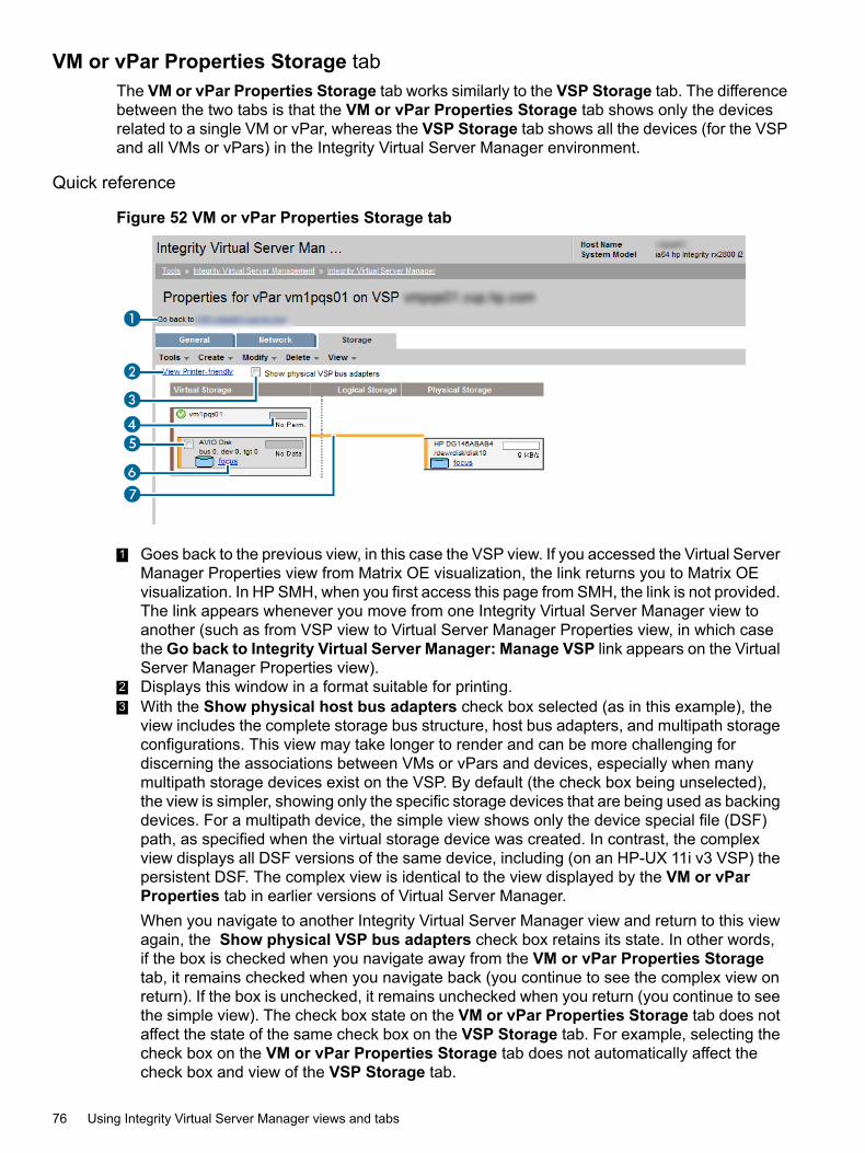
VM or vPar Properties Storage tabThe VM or vPar Properties Storage tab works similarly to the VSP Storage tab. The differencebetween the two tabs is that the VM or vPar Properties Storage tab shows only the devicesrelated to a single VM or vPar, whereas the VSP Storage tab shows all the devices (for the VSPand all VMs or vPars) in the Integrity Virtual Server Manager environment.
Quick reference
Figure 52 VM or vPar Properties Storage tab
1 Goes back to the previous view, in this case the VSP view. If you accessed the Virtual ServerManager Properties view from Matrix OE visualization, the link returns you to Matrix OEvisualization. In HP SMH, when you first access this page from SMH, the link is not provided.The link appears whenever you move from one Integrity Virtual Server Manager view toanother (such as from VSP view to Virtual Server Manager Properties view, in which casethe Go back to Integrity Virtual Server Manager: Manage VSP link appears on the VirtualServer Manager Properties view).
2 Displays this window in a format suitable for printing.3 With the Show physical host bus adapters check box selected (as in this example), the
view includes the complete storage bus structure, host bus adapters, and multipath storageconfigurations. This view may take longer to render and can be more challenging fordiscerning the associations between VMs or vPars and devices, especially when manymultipath storage devices exist on the VSP. By default (the check box being unselected),the view is simpler, showing only the specific storage devices that are being used as backingdevices. For a multipath device, the simple view shows only the device special file (DSF)path, as specified when the virtual storage device was created. In contrast, the complexview displays all DSF versions of the same device, including (on an HP-UX 11i v3 VSP) thepersistent DSF. The complex view is identical to the view displayed by the VM or vParProperties tab in earlier versions of Virtual Server Manager.When you navigate to another Integrity Virtual Server Manager view and return to this viewagain, the Show physical VSP bus adapters check box retains its state. In other words,if the box is checked when you navigate away from the VM or vPar Properties Storagetab, it remains checked when you navigate back (you continue to see the complex view onreturn). If the box is unchecked, it remains unchecked when you return (you continue to seethe simple view). The check box state on the VM or vPar Properties Storage tab does notaffect the state of the same check box on the VSP Storage tab. For example, selecting thecheck box on the VM or vPar Properties Storage tab does not automatically affect thecheck box and view of the VSP Storage tab.
76 Using Integrity Virtual Server Manager views and tabs

4 The utilization meter (bar graph) displays I/O throughput data, if available. The data is a5-minute average that is calculated and updated on 5-minute boundaries. If the data cannotbe displayed, the meter is dimmed (as in the meter below this one) and a label indicates theprobable cause. For a description of meter labels, see the Error messages andtroubleshooting for vPars topic in HP Integrity Virtual Server Manager Online Help. UsingVirtual Server Manager with Matrix Operating Environment, you can click a meter to view asnapshot of Capacity Advisor historical data for storage I/O; this feature is not provided whenusing Virtual Server Manager from HP SMH. For an example utilization history screen andmore information about collecting and viewing utilization data, see the Collect and viewutilization data topic.
5 Allows you to perform an action on the I/O device. Select the box, then select an action fromthe appropriate menu available on the Virtual Server Manager menu bar.
6 Clicking the Focus link limits the display to only the storage devices associated with theobject (in this instance, the devices associated with the indicated AVIO disk) and the objectsdirectly connected to it. All other devices are not shown. To return to the original view, clickthe Show All link visible beneath the Virtual Server Manager menu bar on the focused view.The Show physical VSP bus adapters check box is disabled (dimmed) in the focussedview; you cannot change the Show physical VSP bus adapters state until you return tothe original (unfocussed) view. The simplicity or complexity of the focussed view with respectto VSP bus adapters and so forth is determined by the check box selection at the time thatyou selected the focus link.
7 Color coding indicates that matching components are related.
Screen detailsFor more information about using and interpreting the items displayed in the VM or vParProperties Storage tab, see “Screen details” (page 47).
Virtual Switch (Vswitch) Properties viewYou can access the Vswitch Properties view from any Integrity Virtual Server Manager viewsthat include a link to a virtual switch, such as the VSP Virtual Switches tab, the VSP Networktab, or the VM or vPar Properties Network tab. You can also access the Vswitch Propertiesview by selecting View→ Virtual Switch Properties... (a virtual switch must be selected in thecurrent view).Figure 53 shows a typical Vswitch Properties view. Tabs available from the view are describedin the text that follows. Subsequent sections describe each tab in more detail.
Virtual Switch (Vswitch) Properties view 77
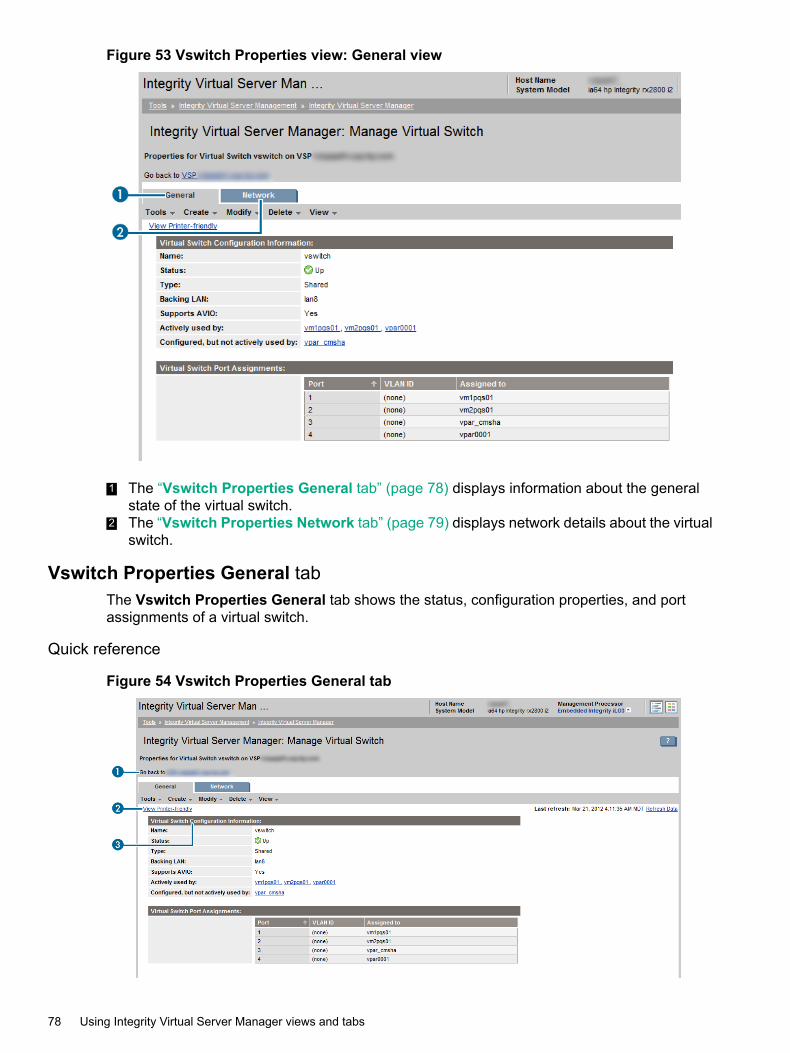
Figure 53 Vswitch Properties view: General view
1 The “Vswitch Properties General tab” (page 78) displays information about the generalstate of the virtual switch.
2 The “Vswitch Properties Network tab” (page 79) displays network details about the virtualswitch.
Vswitch Properties General tabThe Vswitch Properties General tab shows the status, configuration properties, and portassignments of a virtual switch.
Quick reference
Figure 54 Vswitch Properties General tab
78 Using Integrity Virtual Server Manager views and tabs
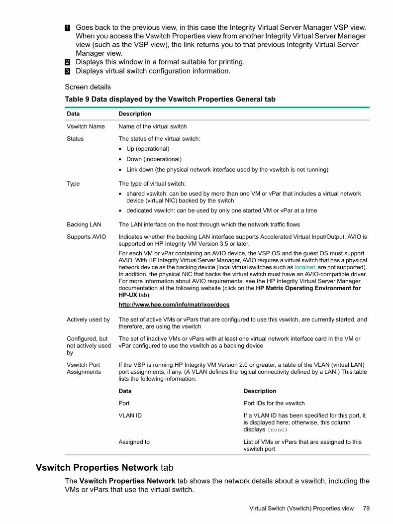
1 Goes back to the previous view, in this case the Integrity Virtual Server Manager VSP view.When you access the Vswitch Properties view from another Integrity Virtual Server Managerview (such as the VSP view), the link returns you to that previous Integrity Virtual ServerManager view.
2 Displays this window in a format suitable for printing.3 Displays virtual switch configuration information.
Screen details
Table 9 Data displayed by the Vswitch Properties General tab
DescriptionData
Name of the virtual switchVswitch Name
The status of the virtual switch:
• Up (operational)
• Down (inoperational)
• Link down (the physical network interface used by the vswitch is not running)
Status
The type of virtual switch:
• shared vswitch: can be used by more than one VM or vPar that includes a virtual networkdevice (virtual NIC) backed by the switch
• dedicated vswitch: can be used by only one started VM or vPar at a time
Type
The LAN interface on the host through which the network traffic flowsBacking LAN
Indicates whether the backing LAN interface supports Accelerated Virtual Input/Output. AVIO issupported on HP Integrity VM Version 3.5 or later.For each VM or vPar containing an AVIO device, the VSP OS and the guest OS must supportAVIO. With HP Integrity Virtual Server Manager, AVIO requires a virtual switch that has a physicalnetwork device as the backing device (local virtual switches such as localnet are not supported).In addition, the physical NIC that backs the virtual switch must have an AVIO-compatible driver.For more information about AVIO requirements, see the HP Integrity Virtual Server Managerdocumentation at the following website (click on the HP Matrix Operating Environment forHP-UX tab):http://www.hpe.com/info/matrixoe/docs
Supports AVIO
The set of active VMs or vPars that are configured to use this vswitch, are currently started, andtherefore, are using the vswitch
Actively used by
The set of inactive VMs or vPars with at least one virtual network interface card in the VM orvPar configured to use the vswitch as a backing device
Configured, butnot actively usedby
If the VSP is running HP Integrity VM Version 2.0 or greater, a table of the VLAN (virtual LAN)port assignments, if any. (A VLAN defines the logical connectivity defined by a LAN.) This tablelists the following information:
Vswitch PortAssignments
DescriptionData
Port IDs for the vswitchPort
If a VLAN ID has been specified for this port, itis displayed here; otherwise, this columndisplays (none)
VLAN ID
List of VMs or vPars that are assigned to thisvswitch port
Assigned to
Vswitch Properties Network tabThe Vswitch Properties Network tab shows the network details about a vswitch, including theVMs or vPars that use the virtual switch.
Virtual Switch (Vswitch) Properties view 79
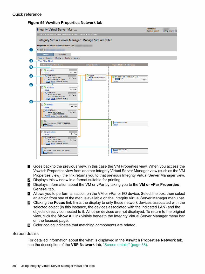
Quick reference
Figure 55 Vswitch Properties Network tab
1 Goes back to the previous view, in this case the VM Properties view. When you access theVswitch Properties view from another Integrity Virtual Server Manager view (such as the VMProperties view), the link returns you to that previous Integrity Virtual Server Manager view.
2 Displays this window in a format suitable for printing.3 Displays information about the VM or vPar by taking you to the VM or vPar Properties
General tab.4 Allows you to perform an action on the VM or vPar or I/O device. Select the box, then select
an action from one of the menus available on the Integrity Virtual Server Manager menu bar.5 Clicking the Focus link limits the display to only those network devices associated with the
selected object (in this instance, the devices associated with the indicated LAN) and theobjects directly connected to it. All other devices are not displayed. To return to the originalview, click the Show All link visible beneath the Integrity Virtual Server Manager menu baron the focused page.
6 Color coding indicates that matching components are related.
Screen detailsFor detailed information about the what is displayed in the Vswitch Properties Network tab,see the description of the VSP Network tab, “Screen details” (page 38).
80 Using Integrity Virtual Server Manager views and tabs

Dynamic I/O Operation Status viewYou can view the status of current and last Dynamic I/O operation by selecting View→DynamiceI/O Operation Status...All I/O devices supported within vPars and Integrity VM guests may be dynamically added ordeleted from running instances of vPars and Integrity VM guests; this capability is called asDynamic I/O. Dynamic addition of I/O devices was first made available with HP-UX vPars andIntegrity VM v6.3. The dynamic deletion is available from v6.3.5.Dynamic addition and deletion are asynchronous operations. The operation is initiated usinghpvmmodify(1M) or vparmodify(1M); the command performs basic validation, informs thevirtualization layers to proceed with the operation and returns immediately. The functional operationproceeds to completion in the background.
Figure 56 Example View Dynamic I/O Operation Status
VM or vPar Configuration Information• IO OLAD operation in progress: Displays the Dynamic IO operation in progress.
• IO OLAD last operation completed: Displays the Dynamic IO operation last completed.
• Device type: The device type of the I/O device.
• Adapter type: The adapter type of the I/O device.
• Ioscan format: The ioscan hardware path of the I/O device.
• Physical Storage Type: The physical storage type of the I/O device.
• Physical Device: Physical device path of the I/O device.
• IO OLAD last operation status: Displays the status of the last completed Dynamic IOoperation.
• IO OLAD last operation error: Displays the error encountered if any during last DynamicIO operation.
To return to the previous screen, click OK.For information on error messages and suggestions for troubleshooting problems pertaining toIntegrity Virtual Server Manager, see the Error messages and troubleshooting topic in HP IntegrityVirtual Server Manager Online Help.
Dynamic I/O Operation Status view 81

82
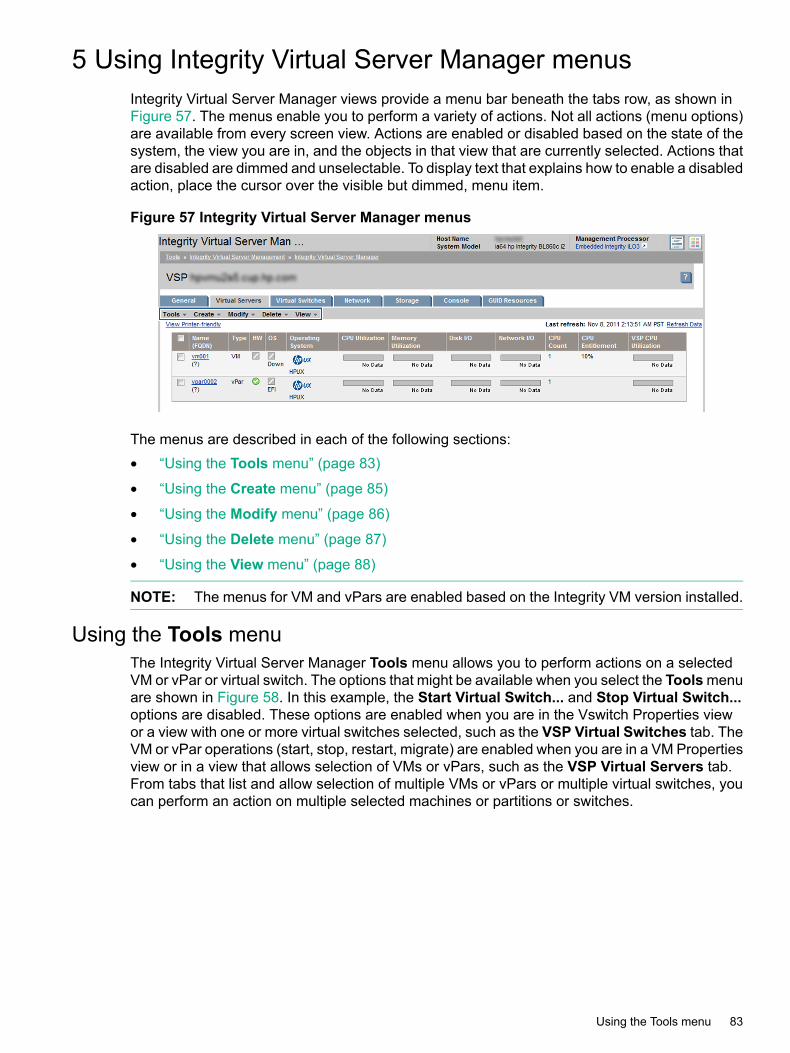
5 Using Integrity Virtual Server Manager menusIntegrity Virtual Server Manager views provide a menu bar beneath the tabs row, as shown inFigure 57. The menus enable you to perform a variety of actions. Not all actions (menu options)are available from every screen view. Actions are enabled or disabled based on the state of thesystem, the view you are in, and the objects in that view that are currently selected. Actions thatare disabled are dimmed and unselectable. To display text that explains how to enable a disabledaction, place the cursor over the visible but dimmed, menu item.
Figure 57 Integrity Virtual Server Manager menus
The menus are described in each of the following sections:• “Using the Tools menu” (page 83)
• “Using the Create menu” (page 85)
• “Using the Modify menu” (page 86)
• “Using the Delete menu” (page 87)
• “Using the View menu” (page 88)
NOTE: The menus for VM and vPars are enabled based on the Integrity VM version installed.
Using the Tools menuThe Integrity Virtual Server Manager Tools menu allows you to perform actions on a selectedVM or vPar or virtual switch. The options that might be available when you select the Toolsmenuare shown in Figure 58. In this example, the Start Virtual Switch... and Stop Virtual Switch...options are disabled. These options are enabled when you are in the Vswitch Properties viewor a view with one or more virtual switches selected, such as the VSP Virtual Switches tab. TheVM or vPar operations (start, stop, restart, migrate) are enabled when you are in a VM Propertiesview or in a view that allows selection of VMs or vPars, such as the VSP Virtual Servers tab.From tabs that list and allow selection of multiple VMs or vPars or multiple virtual switches, youcan perform an action on multiple selected machines or partitions or switches.
Using the Tools menu 83

Figure 58 Integrity Virtual Server Manager Tools menu
Table 10 describes the Tools menu options and where to obtain more information in this manual.More detailed information is provided by the Integrity Virtual Server Manager help.
Table 10 Integrity Virtual Server Manager Tools menu options
More InformationAction SummaryMenu Selection
“Starting VMs” (page 102).nl
This menu is enabled only for VMs.Tools→Start VM...
“Stopping VMs” (page 103).nl
This menu is enabled only for VMs.Tools→Stop Virtual Machine...
“Restarting VMs” (page 104).nl
This menu is enabled only for VMs.Tools→Restart Virtual Machine...
“Suspending VMs” (page 110).nl
This menu is enabled only for VMs.Tools→SuspendVirtual Machine...
“Resuming VMs” (page 111).nl
This menu is enabled only for VMs.Tools→Resume Virtual Machine...
“Booting vPars” (page 127)Boots a vPar starting up the hardwarefor the vPar, taking it from an Off state(powered off) to an On state (poweredon).
Tools→Boot Virtual Partition...
“Stopping vPars” (page 128)Stops a vPar, taking it from an Onstate (powered on) to an Off state(powered off).
Tools→Stop Virtual Partition...
“Resetting vPars” (page 129)Restarts an already started vPar,taking it first to an Off state (poweredoff) and then to an On state (poweredon). Starts a stopped vPar.
Tools→Reset Virtual Partition...
“Starting, stopping, and deleting virtualswitches” (page 116)
Starts a virtual switch, taking it froma Down state (powered off) to an Upstate (powered on).
Tools→Start Virtual Switch...
84 Using Integrity Virtual Server Manager menus

Table 10 Integrity Virtual Server Manager Tools menu options (continued)
More InformationAction SummaryMenu Selection
“Starting, stopping, and deleting virtualswitches” (page 116)
Stops a virtual switch, taking it froman Up state (powered on) to a Downstate (powered off).
Tools→Stop Virtual Switch...
“Migrating Guests” (page 106).This menu is enabled only for VMs.Tools→Migrate Guest...
“Moving suspend files” (page 112).This menu is enabled only for VMs.Tools→VM Move Suspend...
“Opening iLO console” (page 117)This menu is enabled for VMs andvPars.
Tools→Open iLO Console...
“Opening iLO console” (page 117).This menu is enabled for VMs andvPars.
Tools→Open Virtual iLO RemoteConsole...
Using the Create menuTheCreatemenu allows you to create a VM or vPar or virtual switch. Figure 59 shows the choiceswhen you select the Create menu.
Figure 59 Integrity Virtual Server Manager Create menu
Table 11 describes theCreatemenu options and where to obtain more information in this manual.More detailed information is provided by the Integrity Virtual Server Manager help.
Table 11 Integrity Virtual Server Manager Create menu options
More InformationAction SummaryMenu Selection
“Creating VMs” (page 91)This menu is enabled only for VMs.Starts the Create Virtual Machinewizard, which guides you through theprocedure of creating a VM. Eachstep presents a dialog that asks youto specify required information.
Create→Virtual Machine...
“Creating vPars” (page 122)Starts the Create Virtual Partitionwizard, which guides you through theprocedure of creating a vPar. Eachstep presents a dialog that asks youto specify required information.
Create→Virtual Partition...
“Creating virtual switches” (page 113)Creates a new virtual network switch(vswitch) on the VSP. The vswitch isused by the VMs or vPars to connectto the network: one or more VMs orvPars connect to the vswitch, and thevswitch is connected to a VSP'sphysical network device.
Create→Virtual Switch....
Using the Create menu 85
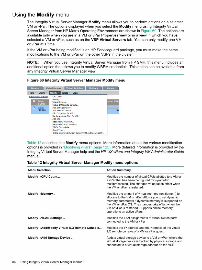
Using the Modify menuThe Integrity Virtual Server Manager Modify menu allows you to perform actions on a selectedVM or vPar. The options displayed when you select the Modify menu using Integrity VirtualServer Manager from HP Matrix Operating Environment are shown in Figure 60. The options areavailable only when you are in a VM or vPar Properties view or in a view in which you haveselected a VM or vPar, such as on the VSP Virtual Servers tab. You can only modify one VMor vPar at a time.If the VM or vPar being modified is an HP Serviceguard package, you must make the samemodifications to the VM or vPar on the other VSPs in the cluster.
NOTE: When you use Integrity Virtual Server Manager from HP SMH, this menu includes anadditional option that allows you to modify WBEM credentials. This option can be available fromany Integrity Virtual Server Manager view.
Figure 60 Integrity Virtual Server Manager Modify menu
Table 12 describes the Modify menu options. More information about the various modificationoptions is provided in “Modifying vPars” (page 125). More detailed information is provided by theIntegrity Virtual Server Manager help and the HP-UX vPars and Integrity VM Administrator Guidemanual.
Table 12 Integrity Virtual Server Manager Modify menu options
Action SummaryMenu Selection
Modifies the number of virtual CPUs allotted to a VM ora vPar that has been configured for symmetricmultiprocessing. The changed value takes effect whenthe VM or vPar is restarted.
Modify→CPU Count...
Modifies the amount of virtual memory (entitlement) toallocate to the VM or vPar. Allows you to set dynamicmemory parameters if dynamic memory is supported onthe VM or vPar OS. The changes take effect when theVM or vPar is restarted. Supports online memoryoperations on active vPars.
Modify→Memory...
Modifies the LAN assignments of virtual switch portsconnected to the VM or vPar
Modify→VLAN Settings...
Modifies the IP address and the Netmask of the virtualiLO remote console of a VM or vPar guest.
Modify→Add/Modify Virtual iLO Remote Console...
Adds a virtual storage device to a VM or vPar, where thevirtual storage device is backed by physical storage andconnected to a virtual storage adapter on the VSP.
Modify→Add Storage Device ....
86 Using Integrity Virtual Server Manager menus

Table 12 Integrity Virtual Server Manager Modify menu options (continued)
Action SummaryMenu Selection
Adds a network device to a VM or vPar, where the networkdevice is associated with a virtual switch. Allows you tocreate a new virtual switch.
Modify→Add Network Device...
This menu is enabled only for VMs.Modify→CPU Entitlement for VM...
This menu is enabled only for VMs.Modify→Hardware Auto Start for VM...
Adds DIO to VM or vPar.Modify→Add DIO...
Replaces the h/w path of a DIO owned by a VM or a vPar.Modify→Replace DIO H/W Path...
Replaces the MAC address of DIOs owned by a VM or avPar.
Modify→Replace DIO MAC Address...
Sets and changes WBEM credentials for VMs or vPars.For information, see “Setting WBEM credentials in HPSMH” (page 16). This menu is available only when usingIntegrity Virtual Server Manager with HP SMH.
Modify→WBEM Credentials...
Modifies a shared VM type to a vPar, and a vPar to ashared VM type using the guest type option.
Modify→Guest Type...
Enables Migration between Itanium 9300 and Itanium9500 based systems for the selected VM.
Modify→Online Migration between Itanium 9300 andItanium 9500...
Using the Delete menuTheDeletemenu allows you to delete one or more VMs or vPars, virtual switches, or I/O devices.Figure 61 shows the choices that might be available when you select the Delete menu. Thechoices are enabled according to the view and tab. In Figure 61, the Virtual Machine... optionis enabled and the Virtual Switch... and I/O Device... options are disabled. The Virtual Machine...option is enabled at the VM Properties view or any VSP or Vswitch Properties tab where youhave selected one or more VMs (such as the VSP Virtual Servers tab, as shown in Figure 61).TheVirtual Switch... option is enabled at the Vswitch Properties view or any VSP or VM Propertiestab where one or more virtual switches are selected. The I/O Device... option is enabled at anyNetwork or Storage tab where one or more I/O devices are selected.From tabs that list and allow selection of multiple VMs or vPars, virtual switches, or I/O devices,you can simultaneously delete all selected objects.
Using the Delete menu 87
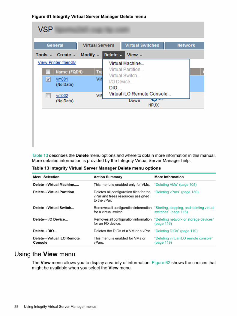
Figure 61 Integrity Virtual Server Manager Delete menu
Table 13 describes theDeletemenu options and where to obtain more information in this manual.More detailed information is provided by the Integrity Virtual Server Manager help.
Table 13 Integrity Virtual Server Manager Delete menu options
More InformationAction SummaryMenu Selection
“Deleting VMs” (page 105)This menu is enabled only for VMs.Delete→Virtual Machine.....
“Deleting vPars” (page 130)Deletes all configuration files for thevPar and frees resources assignedto the vPar.
Delete→Virtual Partition...
“Starting, stopping, and deleting virtualswitches” (page 116)
Removes all configuration informationfor a virtual switch.
Delete→Virtual Switch...
“Deleting network or storage devices”(page 116)
Removes all configuration informationfor an I/O device.
Delete→I/O Device...
“Deleting DIOs” (page 119)Deletes the DIOs of a VM or a vPar.Delete→DIO...
“Deleting virtual iLO remote console”(page 119)
This menu is enabled for VMs orvPars.
Delete→Virtual iLO RemoteConsole
Using the View menuThe View menu allows you to display a variety of information. Figure 62 shows the choices thatmight be available when you select the View menu.
88 Using Integrity Virtual Server Manager menus
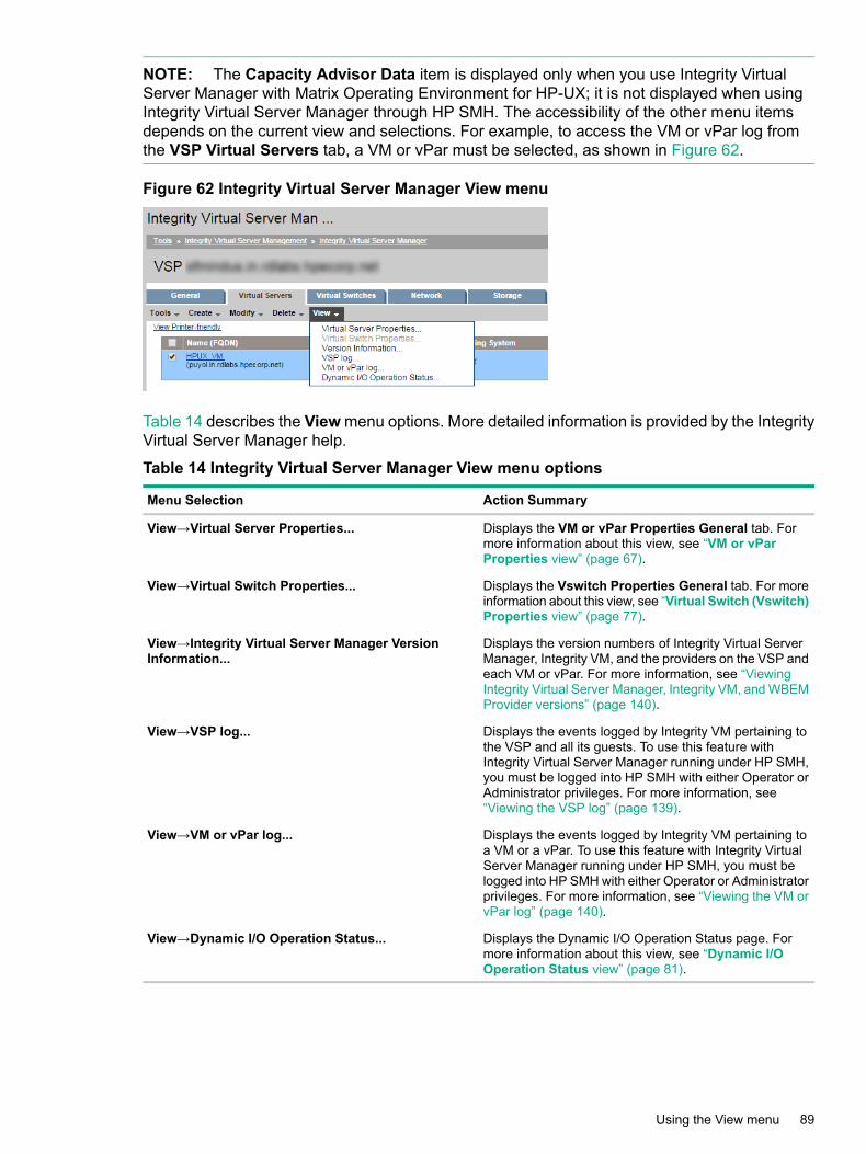
NOTE: The Capacity Advisor Data item is displayed only when you use Integrity VirtualServer Manager with Matrix Operating Environment for HP-UX; it is not displayed when usingIntegrity Virtual Server Manager through HP SMH. The accessibility of the other menu itemsdepends on the current view and selections. For example, to access the VM or vPar log fromthe VSP Virtual Servers tab, a VM or vPar must be selected, as shown in Figure 62.
Figure 62 Integrity Virtual Server Manager View menu
Table 14 describes the View menu options. More detailed information is provided by the IntegrityVirtual Server Manager help.
Table 14 Integrity Virtual Server Manager View menu options
Action SummaryMenu Selection
Displays the VM or vPar Properties General tab. Formore information about this view, see “VM or vParProperties view” (page 67).
View→Virtual Server Properties...
Displays the Vswitch Properties General tab. For moreinformation about this view, see “Virtual Switch (Vswitch)Properties view” (page 77).
View→Virtual Switch Properties...
Displays the version numbers of Integrity Virtual ServerManager, Integrity VM, and the providers on the VSP andeach VM or vPar. For more information, see “ViewingIntegrity Virtual Server Manager, Integrity VM, and WBEMProvider versions” (page 140).
View→Integrity Virtual Server Manager VersionInformation...
Displays the events logged by Integrity VM pertaining tothe VSP and all its guests. To use this feature withIntegrity Virtual Server Manager running under HP SMH,you must be logged into HP SMH with either Operator orAdministrator privileges. For more information, see“Viewing the VSP log” (page 139).
View→VSP log...
Displays the events logged by Integrity VM pertaining toa VM or a vPar. To use this feature with Integrity VirtualServer Manager running under HP SMH, you must belogged into HP SMH with either Operator or Administratorprivileges. For more information, see “Viewing the VM orvPar log” (page 140).
View→VM or vPar log...
Displays the Dynamic I/O Operation Status page. Formore information about this view, see “Dynamic I/OOperation Status view” (page 81).
View→Dynamic I/O Operation Status...
Using the View menu 89

90

6 Working with VMs or vParsThis chapter describes tasks you can perform to create and manage VMs or vPars and theirresources.
NOTE: Integrity Virtual Server Manager version 6.1 supports only one type of guest. If the firstguest created on Virtual Server Manager is a vPar, then only vPar guests can be created on thatVSP. If the first guest created is a VM, then only VMs can be created on that VSP. But, withIntegrity Virtual Server Manager version 6.2, VMs and vPars coexist on the same host.
Working with VMsPlanning VMs
To achieve your goals using VMs, plan the configuration of each VM by assessing its requirementsfor resources on the HP Integrity system on which it will run. For information about how to assessyour system's resources as well as the VMs you will run on the system, and how to map yourVM requirements to the system's resources, see the HP-UX vPars and Integrity VM AdministratorGuide manual, located on the HP Technical Documentation website (click on the HP MatrixOperating Environment for HP-UX tab):http://www.hpe.com/info/matrixoe/docsFor information about AVIO performance tuning, see the latest Integrity VM white papers availablefrom this website.
Creating VMsTo create a VM, Integrity Virtual Server Manager uses the Create Virtual Machine wizard to guideyou through the process. Each step presents a dialog that allows you to specify the requiredinformation. At any time you can get help, return to previous steps, or exit the wizard. By creatinga new VM, you assign attributes and resources to it. This creates an association among thevirtual devices known to the VM and the physical devices managed by the VSP.Where possible, reasonable default values are provided for each dialog. However, the defaultvalues are not necessarily optimal. You must determine what values are optimal based on theunique requirements of your machine (such as the applications you plan to run and theperformance you expect).To access the Create Virtual Machine wizard, selectCreate→Virtual Machine... from the IntegrityVirtual Server Manager menu bar. The Create Virtual Machine wizard leads you through severalscreens in the following order. For more information about any screen, see the correspondingIntegrity Virtual Server Manager help topic.1. Specify VM Identity
Specify the VM name, an optional description, the intended guest operating system, andthe VM hardware startup value (autoboot).
2. Specify Processor EntitlementsThe processor entitlement sets the guaranteed amount of processing power for each virtualCPU in a VM. The processor entitlement is the default entitlement (10%), a percentage ofphysical processor power, or a specific, fixed processor speed. If supported by the versionof Integrity VM running on the VSP, you can specify an entitlement cap and the minimumand maximum number of vCPUs to be allotted to the VM. An entitlement cap is the maximumamount of computing power allotted to a VM for each vCPU.To enable online migration between Itanium 9300 and Itanium 9500 based systems, selectEnable Online Migration between Itanium 9300 and Itanium 9500 check box. By default,this checkbox is not selected.
Working with VMs 91
3. Specify MemorySpecify the amount of memory for the VM. If the VSP has Integrity VM 3.0 or later installedand the OS type you chose in step 1 supports dynamic memory (for example, specifyingHP-UX as the intended guest OS, with Integrity VM 3.0 or later installed on the VSP), thememory screen allows you to set dynamic memory parameters.
NOTE: An up-to-date version of the WBEM Utilization Provider (UP) must be installed onthe VM or vPar to enable HP Capacity Advisor and the memory utilization meters in IntegrityVirtual Server Manager and Integrity VM to reflect the dynamic change in memory. Forinformation about verifying and installing software on VM or vPar, see “System and softwarerequirements” (page 13) and the HP-UX vPars and Integrity VM documentation.
NOTE: VSP might not be able to start the VM if there are insufficient resources to createthe VM. Verifying the memory resources in the third step is to ensure that there are sufficientresources to create the VM. In the final step, if there are insufficient resources and you stillwant to create the VM, you can select the Create VM even if resources are insufficient,missing or unavailable. check box
4. Specify Network DevicesTo add a virtual network device, click Add Network Device... on the first network devicescreen. This brings up the Add Network Device screen. First, select the type of virtualnetwork interface card. The default is an emulated LAN device. You can select AcceleratedVirtual Input/Output (AVIO) device type if AVIO is supported by the version of Integrity VM(Version 3.5 or later) on the VSP and by the intended guest OS.For HP-UX, HP recommends that you install the latest AVIO components for both the VSPand the guest; however, updating both guest and host components at the same time is notmandatory. Updating both components ensures that you always receive the latest bug fixesfor a complete solution. Always check the following software depot website for the latestversion of AVIO software (search for “HPVM AVIO”):www.hpe.com/support/softwaredepotThe guest AVIO drivers are included in the VMGuestSW bundle available from the softwaredepot website. Search for the bundle and make sure you install the latest version.For more information, see the HP Integrity Virtual Machines documentation available athttp://www.hpe.com/info/hpux-hpvm-docs.After you select the virtual network interface type, select the virtual switch from the listprovided or create a virtual switch. To provide network access for the VM, a virtual switchis necessary.
NOTE: Integrity Virtual Server Manager does not automatically update its display of I/Owhile the Create Virtual Machine wizard is being used. If the network or storage I/Oconfiguration on the VSP changes while the Create Virtual Machine wizard is in use, updatethe configuration changes displayed by the wizard by clicking the Refresh Data link.
5. Specify DIOsThis is step five of the Create Virtual Machine wizard. In this step, you define DIOs for theVM. If you want to modify a DIO, you must first delete it and then add the device again withthe correct specifications.You can add HPVM DIOs to a VM to provide near native I/O functionality, manageability,and performance by giving a VM direct access to Host PCI Express (PCIe) functions, whichcan be physical or virtual.To add DIOs:
92 Working with VMs or vPars

1. Select the preferred DIOs from the HPVM DIO table. These DIOs do not have an IPaddress and are not associated with a Vswitch.
2. If you want to enter the Bus, Device, and MAC parameters for the selected DIOs, selectSpecify virtual address parameters (advanced). If you do not want to enter theparameters, leave the check box blank.
3. Click Add to List to add the selected DIOs to the VM. The Specify DIOs page appears,where the selected DIOs are listed.
4. Click Next to move to the next screen of the wizard.Table 15 describes the information which the device selection table displays.
Table 15 DIO selection table: column descriptions
DescriptionParameter name
The H/W Path indicates the functions of a device. Forexample, a function H/W path 0/0/0/3/0/0/0 indicatesfunction 0, which is the last number of the H/W path.Therefore, 0/0/0/3/0/0/[0–N] are all functions of thesame device 0/0/0/3/0/0.
H/W Path
Indicates whether the operation of the DIO is at afunction level or device level. In Function LevelAssignment (FLA), each function is shared amongseveral VMs or vPars. In Device Level Assignment(DLA), an entire device is assigned to the same guestOS. In the DIO pool, all functions of DIOs withdevice-level assignment are placed together. If acommand is issued to one function in the device, allother functions also perform the same operation. Forexample, 0/0/0/4/0/0/0 and 0/0/0/4/0/0/1 aredevice-level functions and belong to the device,0/0/0/4/0/0. They are placed in a single cell in the DIOpool. If you select them from the host or HPVM table,the command preview field displays only the firstfunction, 0/0/0/4/0/0/0.
Assignment Level
Indicates the type of DIO driver. The driver used mustbe compatible with DIO. For example, HPUX 11i v31112/1203 iexgbe guest driver with DIO support.
Driver Type
Displays a description of the DIO network adaptor. Forexample, AM225-60001 HP Integrity PCIe 2-port10GbE-SR Fabric Adapter.
Description
Indicates the label of the DIO.Label
Indicates the VMs or vPars configured to use this DIO.Used by Guest
6. Each virtual storage device is backed by physical storage in the VSP system. A physicalstorage device can be a disk device, a logical volume, a DVD or CD, a DVD writer (burner),a tape device, a tape changer, an existing file (a file or directory being used as the backingstorage device for a virtual storage device of an already-existing VM on the VSP), or a newfile that Integrity Virtual Server Manager allows you to create as a backing storage devicefor a virtual disk (Virtual FileDisk). When you add a DVD writer, tape device, or changer,they are added as attached devices.You can add attached devices only if they are using anemulated SCSI adapter. You cannot use Integrity Virtual Server Manager to add an attachedAVIO device; to add such a device to a VM, use the hpvmdevmgmt command at the VSP.To add a virtual storage device, click Add Storage Device... on the first storage devicescreen. This brings up the Add Storage Device screen. First, select the type of virtualstorage adapter. You can select Accelerated Virtual Input/Output (AVIO) adapter type ifAVIO is supported by the version of Integrity VM (Version 3.5 or later) on the VSP and bythe intended guest OS (HP-UX 11i v3 only).
Working with VMs 93
NOTE: Use of VIO is not supported starting with Integrity VM version 6.1 or later. Hence,from Integrity VM version 6.1 onwards, use of Emulated SCSI adapter to add a storagedevice is not supported from Integrity Virtual Server Manager.
If the VSP is running HP-UX 11i v3, the Add Storage Device screen gives you the choiceof listing storage devices by their agile address (the default) or by their legacy address. HPrecommends using agile device addressing when configuring storage devices. This providesbenefits especially for multipath devices. With legacy addressing, the screen lists one entryfor each path to a storage device that has multiple paths. With agile addressing, the screenlists only one entry for each multipath storage device. To change the addressing schemefor viewing, select the appropriate addressing scheme. If the VSP runs an earlier version ofHP-UX, you are not given a choice: the table lists devices by the legacy addressing schemeonly. For more information about agile addressing, see the VSP Storage tab help topic.For more information on AVIO devices and on agile addressing, see the HP-UX vPars andIntegrity VM documentation.After you select the virtual storage adapter type, select the physical backing device from thelist of devices provided in the device selection table (such as disk, DVD, tape, LVM volume,files).
94 Working with VMs or vPars

NOTE: The list can include file and directory backing devices that have not been associatedwith a particular VM, or that were associated with VMs that have been removed or fromwhich the associated virtual devices have been removed. You can make these devicesavailable to Integrity Virtual Server Manager by adding them to the Integrity VM devicedatabase. One advantage is that this allows you to populate the Integrity VM device databasewith entries for OS installation DVD images that might be used when creating and provisioningseveral VMs. When you use Integrity Virtual Server Manager to add a virtual DVD to a VM,the image file shows up in the list of storage backing devices to choose from, saving youfrom having to type the name of the image file or to browse for it.At the VSP command line, add a file as a guest device (gdev) to the device managementdatabase by specifying the hpvmdevmgmt command with the USAGE attribute value as eitherUSAGE=DISK or USAGE=DVD. As a result, the Integrity Virtual Server Manager screen includesthe file in the list of backing devices you can choose from. The file is listed as a backingdevice for either a virtual disk or a virtual DVD, depending on the value of the USAGE attribute.For example, if you add file /images/myos.iso to the device management database,specifying attribute USAGE=DVD, then /images/myos.isowill appear in the Integrity VirtualServer Manager list of backing devices as a possible backing device for a virtual DVD. Ifyou add a file to the database without specifying the USAGE attribute, the file is not includedin the list of possible backing devices.If you add a directory to the database, it is included in the list as a possible backing devicefor a virtual DVD. Do not specify the USAGE attribute for a directory; the attribute is not neededfor a directory.To ensure that a device database entry is preserved in the VSP device management databasefor future selection, even when the associated virtual device is removed from the VM, oreven when all VMs using the entry as a backing device are deleted from the VSP, you canenter the hpvmdevmgmt command with the PRESERVE attribute specified as PRESERVE=YES.When you use the hpvmdevmgmt command to create a file as a backing device for a disk,specify the size (-S) and -A attributes to ensure that the file is included in the list of possiblebacking devices. Specifying these two attributes automatically sets USAGE=DISK andPRESERVE=YES.When you use Integrity Virtual Server Manager to create a file as a backing device for adisk, the PRESERVE attribute is set as PRESERVE=YES.
NOTE: If you use Integrity Virtual Server Manager to manage a VSP running Integrity VMVersion 3.5 or earlier, Integrity Virtual Server Manager does not fully support virtual devicespecial files located in /hpap (introduced in HP StorageWorks Secure Path software Version3.0F SP2) as backing devices for virtual storage. When you use Integrity Virtual ServerManager to add a storage device on a VM, Integrity Virtual Server Manager does not displaydevice files in /hpap as possible backing devices to choose from.To add a virtual storage device that uses a virtual device special file in /hpap to a new VMon a VSP running Integrity VM Version 3.5 or earlier, use the Integrity VM hpvmcreatecommand. For more information about these commands, see theHP-UX vPars and IntegrityVM Administrator Guide manual.
7. SummaryReview the identity and resources specified for the new VM and preview the command thatwill be used to create it. This summary step allows you to review all information before thenew VM is created.
Working with VMs 95

At this step, you can still cancel (exit the Create VM wizard) or return to modify previoussteps in the wizard. When you click Finish, the wizard executes the hpvmcreate commandsdisplayed in the Command Preview area:
• If the Create VM even if resources are insufficient, missing or unavailable checkbox is not selected, the wizard executes the first of two commands (hpvmcreate -s)to check for resource availability and other issues without actually creating the VM. Thiscommand reports any errors or warnings at the top of the page. If warnings or errorsare detected, the VM will not be created. Upon analyzing any reported warnings, youcan choose to create the VM anyway by selecting the check box and clicking Finishagain.If no serious problems are detected by the first command, the wizard then executes thesecond command (hpvmcreate -F), which creates the VM.
• If the Create VM even if resources are insufficient, missing or unavailable checkbox is selected, the wizard does not check for resource warnings. It simply runs thehpvmcreate -F to create the VM even if potential resource issues exist (but not if afatal error is detected). For example, if this check box is selected, you can create a VMthat uses a physical disk that some other running VM is already using. As anotherexample, you can create a VM for which you incorrectly specified a storage device file.You can correct these kinds of problems after the VM is created and before it is started.For information about problem solving, see “Troubleshooting VM or vPar problems”(page 152).
8. Specify VLAN IDsIf the VSP supports vswitch VLANs (virtual LANs), and virtual NICs (vNICs) are specifiedfor the new VM, then you can assign VLAN IDs to the newly created VM. You can assign aVLAN ID to the vswitch port connected to each virtual NIC in the VM. By default, VLANs arenot specified (VLAN ID is “none”). When you click OK on this page, any modifications to theVLAN IDs are updated, after which the Create Virtual Machine wizard Next Steps page isdisplayed.
9. Next Steps for VMAfter creating the new VM, Integrity Virtual Server Manager presents you with the next stepsyou can take to manage and use the new VM. The steps presented depend on theenvironment in which you created the VM. For example, when VM scheduling on a VSP ismanaged by Global Workload Manager (gWLM), the Next Steps page advises you toassociate the VM with a gWLM policy and add the VM to a Shared Resource Domain (SRD).You cannot start the VM until you complete that action.If the new VM includes AVIO devices (AVIO support is provided on HP Integrity VM Version3.5 or later), you are advised to make sure the appropriate OS that supports AVIO is installedon the VSP and the VM. If the intended OS on the VM does not support AVIO, you arewarned of this. In addition, HP strongly recommends that AVIO components (such as driversand libraries) on the VM and VSP be updated to the latest release of the OS. For moreinformation about AVIO requirements, see the HP-UX vPars and Integrity VM AdministratorGuide manual.Other steps you can take include starting the virtual hardware for the VM, accessing the VMconsole, adding additional software (provider components) needed to support managementof the VM, getting information about the VM, and tuning the performance of the VM.
NOTE: Any devices added using the Create Virtual Machine wizard are not functional onthe VM until the new VM is started. Certain devices are not seen in a Integrity Virtual ServerManager Storage tab until the VM is started.
You can configure the VM's Extensible Firmware Interface (EFI) to boot the guest OSautomatically when the VM is started (powered on). Configure EFI when the VM has been
96 Working with VMs or vPars

started and before booting the OS. You can interact with EFI through the virtual ManagementProcessor (vMP) for the VM. The vMP provides access to the console for the VM. To interactwith vMP, use the hpvmconsole command. For more information, see the HP-UX vParsand Integrity VM Administrator Guide manual.If you are using Integrity Virtual Server Manager from HP SMH, click OK to finish. IntegrityVirtual Server Manager displays the page from which you initiated the Create Virtual Machinewizard.If you are using Integrity Virtual Server Manager from HP Matrix Operating Environment,click Apply gWLM Policy. To skip this step and add the new VM to the SRD later, clickApply Later (you must click either button). When you click Apply Later, Integrity VirtualServer Manager displays the page from which you initiated the Create Virtual Machinewizard. When you are ready to add the VM to the SRD, select the VM from the appropriatescreen (for example, from the VSP Virtual Servers tab) and then select Policy →ApplygWLM Policy ... from the Integrity Virtual Server Manager menu bar. For more information,see the Integrity Virtual Server Manager Policy Menu help topic.
NOTE: After creating a VM using Integrity Virtual Server Manager, if you return immediatelyto HP Matrix OE visualization, the machine might not yet appear in HP Matrix OE visualization.This means Systems Insight Manager/HP Matrix Operating Environment has not yetcompleted identifying the new VM. However, it appears when the identification processcompletes (usually within a minute or two).
Modifying VMsTo modify a VM, select one of the following items from the Integrity Virtual Server ManagerModifymenu. For more information about any item, see the corresponding Integrity Virtual ServerManager help topic.
NOTE: You cannot modify a VM that is currently migrating online. You must wait until migrationcompletes. You cannot modify a VM that has migrated to another VSP (the target): the VM (onthe source VSP) is in the Not Runnable state.
• Virtual Machine vCPU Entitlement to modify the processor entitlement of a selected VM.If supported by the version of Integrity VM running on the VSP, you can modify the entitlementcap. An entitlement cap is the maximum amount of computing power allotted to a VM foreach vCPU.
NOTE: If the VM is being managed by gWLM, you cannot modify the vCPU entitlement.When you access the Virtual Machine vCPU Entitlement page, the following error messageis displayed, where virtual-machine-name is the name of the VM:The processor entitlement for VM virtual-machine-name cannot bemodified because it is being managed by gWLM. To adjust the processorentitlement for this VM, use gWLM to change the policy associatedwith this VM.
To create or modify the gWLM policy for this VM, use the Policymenu (available when usingIntegrity Virtual Server Manager with Matrix Operating Environment for HP-UX).
• Virtual Machine Memory to modify the amount of memory for a selected VM. If the VSPhas Integrity VM 3.0 or later installed and the OS type for the VM supports dynamic memory,the dynamic memory parameters are shown, and you can modify them. Changes to memorytake effect when the VM is restarted.
Working with VMs 97

NOTE: An up-to-date version of the WBEM Utilization Provider (UP) must be installed onthe VM to enable HP Capacity Advisor and the memory utilization meters in Integrity VirtualServer Manager and Integrity VM to reflect the dynamic change in memory. For informationabout verifying and installing software on VMs, see “System and software requirements”(page 13) and the HP Integrity Virtual Machines documentation.
• Virtual Machine vCPU Count to modify the number of virtual CPUs for a selected VM orCPUs for a selected vPar. If supported by the version of Integrity VM running on the VSP,you can modify the minimum and maximum number of vCPUs to be allotted to the VM orCPUs to the vPar. Changes take effect when the VM or vPar is restarted.
• Virtual Machine VLAN Settings to modify the VLAN associated with the VM or vPar.
• Add/Modify Virtual iLO Remote Console to modify the IP Address and Net mask detailsof virtual iLO remote console of a VM or vPar. If the VM or vPar does not have a virtual iLOassociated with it, you can create the virtual iLO remote console from theAdd/Modify VirtualiLO Remote Console screen.
• Hardware Auto Start for VM to specify whether the VM should start automatically whenIntegrity VM is started or whether the VM will be started manually.
• Add DIO to add DIOs to a guest VM or vPar.
• Replace DIO H/W path to replace the h/w path of a DIO owned by a guest VM or vPar.
• Replace DIO MAC address to replace the MAC address of DIOs owned by a guest VM orvPar.
• WBEM Credentials to set and change WBEM credentials for VMs or vPars.
• Add Storage Devices to add storage devices for VMs or vPars.
98 Working with VMs or vPars

NOTE: The list of possible backing devices for the storage device you want to add caninclude file and directory backing devices that have not been associated with a particularVM or vPar, or that were associated with VMs or vPars that have been removed or fromwhich the associated virtual devices have been removed.You can create a file as a backing storage device for a virtual disk. You can add DVD burners,tape devices, and changers if they are emulated SCSI adapters; they are added as attacheddevices. You cannot use Integrity Virtual Server Manager to add an attached AVIO device;to add such a device to a VM or vPar, use the hpvmdevmgmt command at the VSP. Formore information, see the Modify→Add Storage Device ... help topic.Use of VIO is not supported starting with Integrity VM version 6.1 or later. Hence, fromIntegrity VM version 6.1 onwards, use of Emulated SCSI adapter to add a storage deviceis not supported from Integrity Virtual Server Manager.
NOTE: If you use Integrity Virtual Server Manager to manage a VSP running Integrity VMVersion 3.5 or earlier, Integrity Virtual Server Manager does not fully support virtual devicespecial files located in /hpap (introduced in HP StorageWorks Secure Path software Version3.0F SP2) as backing devices for virtual storage. When you use Integrity Virtual ServerManager to add a storage device on a VM, Integrity Virtual Server Manager does not displaydevice files in /hpap as possible backing devices to choose from. If a virtual storage deviceusing an /hpap device special file already exists on a VM managed by Integrity VirtualServer Manager, Integrity Virtual Server Manager displays it on the VSP Storage and VMProperties Storage tabs as an unknown device (using the question mark icon, ). IntegrityVirtual Server Manager displays the correct device special file name (for example,/hpap/rdsk/hpap1) but the box representing this device is not connected to the boxesthat represent the physical storage devices associated with that virtual device special file.In general, Integrity Virtual Server Manager correctly displays only those device special fileslocated in /dev.To add a virtual storage device that uses a virtual device special file in /hpap to an existingVM on a VSP running Integrity VM Version 3.5 or earlier, use the Integrity VM hpvmmodifycommand. For more information about these commands, see theHP-UX vPars and IntegrityVM Administrator Guide manual.
• Add Network Device to add network devices and vswitches for VMs.
NOTE: Any network or storage devices that you add are not functional on the VM until the VMor vPar is started or restarted. When you add an I/O device to a started VM, it might not appearon the Network or Storage tab until the VM is stopped or restarted. For a started vPar, networkor storage cannot be modified. If you add an I/O device to a stopped VM or vPar, the tab displaysthe device immediately.
NOTE: If the VM being modified is an HP Serviceguard package, you must make the samemodifications to the VM on the other VSPs in the cluster.
Guest TypeYou can modify a shared VM type to a vPar, and a vPar to a shared VM type using the GuestType option in the Modify menu.
Modify VM type to vPar
When you convert a shared VM type to a vPar, its CPU entitlement is set to 100%. Also, BootAttribute is set to Auto and resource reserved is set to True. Other configuration settings orattributes are not modified.To convert a shared VM type to a vPar:
Working with VMs 99

1. Select a checkbox of VM type.
Figure 63 Modify VM Type to vPar — Step 1
2. From the Modify menu, select Guest Type.
Figure 64 Modify VM Type to vPar — Step 2
Figure 65 displays all the conversion details for the VM type selected:
Figure 65 Modify VM Type to vPar — Step 3
Conversion details are as follows:
• Guest Name: Indicates the present guest name selected for conversion.
• Current Type: Indicates the current guest type (VM) used for conversion.
• Proposed Type: Indicates the proposed conversion type (vPar).General Preview section gives an overview of the old and new values of the selected guesttype .
3. After verifying the conversion details, click OK .Figure 66 displays the selected VM type converted to vPar for the guest vPar002:
100 Working with VMs or vPars
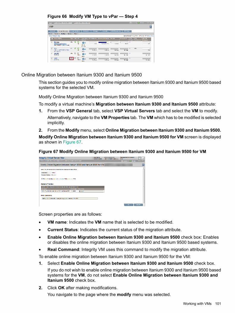
Figure 66 Modify VM Type to vPar — Step 4
Online Migration between Itanium 9300 and Itanium 9500This section guides you to modify online migration between Itanium 9300 and Itanium 9500 basedsystems for the selected VM.
Modify Online Migration between Itanium 9300 and Itanium 9500
To modify a virtual machine’s Migration between Itanium 9300 and Itanium 9500 attribute:1. From the VSP General tab, select VSP Virtual Servers tab and select the VM to modify.
Alternatively, navigate to the VMProperties tab. The VMwhich has to be modified is selectedimplicitly.
2. From theModifymenu, selectOnline Migration between Itanium 9300 and Itanium 9500.Modify Online Migration between Itanium 9300 and Itanium 9500 for VM screen is displayedas shown in Figure 67.
Figure 67 Modify Online Migration between Itanium 9300 and Itanium 9500 for VM
Screen properties are as follows:
• VM name: Indicates the VM name that is selected to be modified.
• Current Status: Indicates the current status of the migration attribute.
• Enable Online Migration between Itanium 9300 and Itanium 9500 check box: Enablesor disables the online migration between Itanium 9300 and Itanium 9500 based systems.
• Real Command: Integrity VM uses this command to modify the migration attribute.To enable online migration between Itanium 9300 and Itanium 9500 for the VM:1. Select Enable Online Migration between Itanium 9300 and Itanium 9500 check box.
If you do not wish to enable online migration between Itanium 9300 and Itanium 9500 basedsystems for the VM, do not select Enable Online Migration between Itanium 9300 andItanium 9500 check box.
2. Click OK after making modifications.You navigate to the page where the modify menu was selected.
Working with VMs 101

NOTE: The modified value appears when the virtual machine is started the next time.
Starting VMsStarting a VM starts the virtual hardware for the VM. The VM enters an On state (powered on).The Start and Restart functions are similar except the Start function does not stop and restart aVM that is already started (it leaves the started machine as is), while the Restart function does.Use Restart instead of Start when you have several VMs that you want newly started, somewhich are already started and some currently stopped. The Restart function takes care of all theVMs (in contrast, the Start function does not restart the already started machines). If you do notwant the already started machines stopped and restarted (you just want the stopped machinesstarted), use the Start function instead. For information about restarting VMs, see “RestartingVMs” (page 104).
NOTE: You cannot start a VM that is currently migrating online. You must wait until migrationcompletes. If the selected VM has migrated to another VSP (the target), the VM (on the sourceVSP) is in the Not Runnable state: you cannot start a VM in this state.
To start one or more selected VMs, perform the following steps.1. From the VSP General tab, select the VSP Virtual Servers tab (or any tab that allows you
to select one or more VMs).2. Select one or more VMs to start by clicking the appropriate check boxes.
Alternatively, you can access the VM Properties view, in which case no selection is necessary;the VM being viewed is implicitly selected.
3. Select Tools→Start Virtual Machine... from the Integrity Virtual Server Manager menu bar.A page similar to that shown in Figure 68 is displayed.
Figure 68 Start Virtual Machine page
4. In the example shown in Figure 68, one VM will be started. The Note column indicates thatone of the selected VM is already started. TheCommandPreview area shows the commandsthat Integrity VM will perform to start the VM.Click OK to start the VM.
When a VM is started, it is in the On state (powered on). You can then perform the functions youwant.
102 Working with VMs or vPars

NOTE: Depending on the settings in the VM's Extensible Firmware Interface (EFI), starting aVM might not boot the operating system. For more information, see “Creating VMs” (page 91).
Once a VM is started, the resources assigned to the VM are allocated for its use. The VSPensures that the resources required by the VM are available in the current VSP systemenvironment. If the VM cannot be started, Integrity Virtual Server Manager displays messagesindicating which resources cannot currently be provided.For information about possible reasons that a VM might not start, see “Troubleshooting VM orvPar problems” (page 152).
Stopping VMsTo stop one or more VMs, perform the following steps. This action allows you to stop the virtualhardware for a VM. When stopped, a VM enters an Off state (powered off) and the VM is halted.Once a VM is stopped, the resources assigned to it no longer are allocated and are now availablefor use by other VMs.
NOTE: If the OS is running on a VM that you want stopped, HP recommends that you shutdown the OS before stopping the VM. This ensures that all applications are shut down cleanly.You cannot stop a VM that is currently migrating online. You must wait until migration completes.If the selected VM has migrated to another VSP (the target), the VM (on the source VSP) is inthe Not Runnable state: attempts to stop the VM will fail.
1. From the VSP view, select the VSP Virtual Servers tab (or any tab that allows you to selectone or more VMs).
2. Select one or more VMs to stop by clicking the appropriate check boxes.Alternatively, you can access the VM Properties view, in which case no selection is necessary;the VM being viewed is implicitly selected.
3. Select Tools→Stop Virtual Machine... from the Integrity Virtual Server Manager menu bar.This displays a page similar to that shown in Figure 69.
Figure 69 Stop Virtual Machine page
4. In the screen example shown in Figure 69, one of the selected VMs is going to be stopped(vm001), while one is already stopped (vm002). The OS is running on one of the VMs andyou have to shut down the OS on that machine before stopping it.The How to Stop options allow you to control how a VM is stopped:
• Graceful. This is the default. With a graceful stop, the VM notifies the guest OS of animpending shutdown. This advance notice gives the OS an opportunity to performcleanup operations before its VM is powered off. A graceful stop typically takes 30 to
Working with VMs 103

60 seconds, but can take as long as 5 minutes because Integrity VM waits for the OSto complete its cleanup operations.
• Forced. A forced stop is the equivalent of a power failure and gives no warning to theguest OS. Because the guest OS receives no advance notice of the power off operation,the OS has no opportunity to perform a crash dump or perform any system cleanuptasks.
If you want to set a forced stop for the machines, click the Forced option; otherwise, skip tothe next step.
5. The Command Preview area shows the commands that Integrity VM will perform to stopthe VMs.Click OK to perform the action.
Restarting VMsWhen you choose to restart one or more VMs, Integrity Virtual Server Manager stops a VM thatis already started, and then restarts it; if a machine is stopped, Integrity Virtual Server Managerstarts it. Once a VM starts, the resources assigned to the VM are allocated for its use.The Restart and Start functions are similar except the Restart function first stops a VM that isalready started, while the Start function does not (it leaves the started VM as is). Use Restartinstead of Start when you have several VMs that you want newly started, some which are alreadystarted and some currently stopped. The Restart function takes care of all the VMs (in contrast,the Start function does not restart the already started machines). However, if you do not wantthe already started machines stopped (you just want the stopped machines started), use theStart function instead. For information about the start function, see “Starting VMs” (page 102).
NOTE: If the OS is running on a VM that you want stopped, HP recommends that you shutdown the OS before stopping the VM. This ensures that all applications are shut down cleanly.You cannot start a VM that is currently migrating online. You must wait until migration completes.If the selected VM has migrated to another VSP (the target), the VM (on the source VSP) is inthe Not Runnable state: you cannot start a VM in this state.
To restart one or more VMs, perform the following steps:1. From the VSP General tab, select the VSP Virtual Servers tab (or any tab that allows you
to select one or more VMs).2. Select the VMs to restart by clicking the appropriate check boxes.
Alternatively, you can access the VM Properties view, in which case no selection is necessary;the VM being viewed is implicitly selected.
3. Select Tools→Restart Virtual Machine... from the Integrity Virtual Server Manager menubar. This displays a page similar to that shown in Figure 70.
104 Working with VMs or vPars

Figure 70 Restart Virtual Machine page
4. In the screen example shown in Figure 70, one VM (vm001) will be stopped (gracefully) andrestarted. A message indicates that this machine have an active operating system that shouldbe shut down prior to stopping the VM. TheHow to Stop options allow you to control whetherthe VMs are stopped gracefully (the default) or forcefully. For a description of each stopoption, see “Stopping VMs” (page 103).If you want to set a forced stop for the machines, click the Forced option; otherwise, skip tothe next step. If all machines are already stopped, skip to the next step (the How to Stopoptions are irrelevant).As noted, if the OS is running on a VM that is already started, shut down the OS beforeinitiating the restart in the next step.
5. The Command Preview area shows the commands that Integrity VM will perform to restartthe VMs.Click OK to perform the action.
For information about possible reasons that a VM might not start, see “Troubleshooting VM orvPar problems” (page 152).
Deleting VMsTo delete a VM, select Delete→Virtual Machine... from the Integrity Virtual Server Managermenu bar. The Virtual Machine... menu option is enabled in the VM Properties view or whenone or more VMs are selected in any of the tabs that list VMs, such as in the VSP Virtual Serverstab. From tabs that list and allow selection of multiple VMs, you can simultaneously delete multipleVMs that are selected.
NOTE: Before deleting a VM, you must first stop the VM (put it in the Off state). For instructions,see the section “Stopping VMs” (page 103).
Deleting a VM removes the configuration definition for a VM and frees any resources assignedto the VM, making the resources available to be assigned to other VMs. Deleting a VM does notdelete files and data residing on the virtual storage or backing storage that was assigned to theVM.By default, vswitch VLAN port assignments are removed when the VM is deleted. If any of theports are connected to other VMs that are not being removed, those port assignments are notremoved. Clearing the Remove VLAN Assignment check box causes vswitch VLAN portassignments to remain after the VM is deleted.
Working with VMs 105
NOTE: You cannot delete a VM that is currently migrating online. You must wait until migrationcompletes.
NOTE: Using Integrity Virtual Server Manager with Matrix Operating Environment for HP-UX,if you create a VM and then delete it before the new VM has been identified by Systems InsightManager, the VM might appear in HP Matrix OE visualization as though it had not been deleted.The appearance of the VM in HP Matrix OE visualization depends on when the deletion occurredduring the Systems Insight Manager identification process. In addition, if you decide to deletethe VM soon after creating it, wait a few minutes before doing so. If the deleted VM does appearin HP Matrix OE visualization, delete it from the Systems Insight Manager All System view. (Fromthe Systems Insight Manager Systems and Event Collections list in the navigation area on theleft, selectAll Systems.) For more information, see the HPMatrix Operating Environment LogicalServer Management User Guide.This is not an issue when using Integrity Virtual Server Manager from HP SMH.
Migrating Guests
OverviewThis topic presents an overview of guest migration and of the Migrate guest wizard that allowsyou to set up and initiate migration of guests from your Integrity Virtual Server Manager's VSP(the migration source) to another VSP (the migration target).The wizard allows you to perform either online or offline migration:
• Online migration migrates a guest that is running, moving the guest OS and applicationswithout disrupting service. All guest I/O connections to network and storage devices remainactive throughout the migration, and the guest OS and its applications continue operatingwithout requiring a reboot or application restart.
• Offline migration migrates the configuration of a guest that is not running.Some of the most common reasons for migrating guests online include the need to:• Vacate the source VSP system for maintenance purposes without disrupting services
• Perform a rolling upgrade of a VSP, moving its running guests to another VSP, upgradingthe VSP, then moving the guests back
• Populate a new VSP with one or more guests already configured and tested on the source
• Move guests to take advantage of a particular resource or feature on the target VSP, withoutlosing application availability
• Balance VSP workloads
• Optimize physical resource utilizationOnline migration of guests enables a higher level of workload-to-resource alignment, flexibility,and agility.Reasons for migrating a guest offline include the need to:• Move a stopped guest's configuration information
• Save VSP resources while migrating guests (for example, memory and CPUs are notconsumed during offline migration)
• Copy local storage, logical volumes, or file-backed storage to the target VSP (such storagecannot be migrated online)
• Migrate a guest between VSP that might have different processor types, making onlinemigration impossible
106 Working with VMs or vPars

The Migrate Guest wizard is started by selecting Tools→Migrate Guest... from the IntegrityVirtual Server Manager menu bar. The menu item is enabled from the VM/vPar Properties view,from which you can migrate the one viewed guest, or from a tab on which one or more guestsare selected, such as the VSP Virtual Servers tab, from which you can migrate multiple guestsat the same time. For more information about starting the wizard, see“Starting the Migrate Guest wizard” (page 109).The Migrate Guest wizard guides you through a two-step procedure. The screen for the first stepprompts you to specify the target VSP. The screen for the second step allows you to preview theHP Integrity Virtual Machine commands that will be invoked to initiate the migration and allowsyou to initiate the migration.Using the Migrate Guest wizard, you can migrate guests from the VSP you are currently usingwith Integrity Virtual Server Manager to another VSP; you cannot use the wizard to migrate guestsfrom another VSP to the current Integrity Virtual Server Manager VSP.While a guest is being migrated to another VSP, you cannot stop, start, restart, modify, or deletethat guest. You can continue using Integrity Virtual Server Manager for other purposes.
NOTE: If the guest is configured as a Serviceguard package, the wizard allows you to migratethe guest online or offline. However, you cannot migrate a guest that is configured as aServiceguard cluster node.When migrating a guest that is configured as a Serviceguard package, Serviceguard protectionis suspended temporarily during the migration.Capacity Advisor cannot collect utilization information for a guest that is being migrated.For more information about Serviceguard and Capacity Advisor requirements andrecommendations pertaining to guest migration, see “Planning requirements andrecommendations” (page 107).
Planning requirements and recommendationsSuccessful migration of a guest requires that the source and target hosts be configuredappropriately. If they are configured properly before migration of a guest, the migration taskcompletes more quickly. Configuration requirements for online migration are more elaborate thanfor offline migration.Some of the basic migration requirements include the following; for complete details, see theHP-UX vPars and Integrity VM Administrator Guide manual:
• For online migration, the source and target VSPs must be running HP Integrity VM Version4.1 or later.
• The source and target VSPs must conform to the operating system requirements, and bothmust be able to provide the allocated resources to the guest being migrated.
• The target VSP must be accessible from the source VSP.
• Resources used by the guest must be configured symmetrically on both the source andtarget VSP.
• You can migrate guests that use both the virtual I/O (VIO) and the accelerated virtual I/O(AVIO) drivers for storage and network. Only whole disk SAN storage and ejected file-backedDVDs can be migrated while the guest is online. File and logical volume backing storageare not supported for online migration of guests.
Working with VMs 107

• Online migration requires that both the source and target VSP be licensed and enabled forsuch migration. The licensing is included with a bundle that must be installed on each VSP;for more information, see the HP-UX vPars and Integrity VM Administrator Guide manual.
• Online guest migration requires that the guest be enabled for online migration (the VSPadministrator can enable a guest by using the hpvmmodify -xonline_migration=enabled command).
Serviceguard requirements and recommendations
For online migration of a guest configured as a Serviceguard package, package switching forthe migrating guest package is disabled before migration begins and then re-enabled immediatelyafter the migration finishes. Therefore, the guest software is not protected by Serviceguard duringthe migration process. If a failure occurs during migration, you must manually re-enable packagefailover after the migration completes and restart the guest by running it on one of the Serviceguardcluster nodes.If temporary loss of failover protection is not tolerable, disable online migration for the guest. Forexample, to disable the guest named sgnode, run the hpvmmodify command on the VSP asfollows:hpvmmodify -P sgnode -x online_migration=disabled
Do not attempt online migration of a guest configured as a Serviceguard cluster node. If aServiceguard node is migrated while online, it might lose connection to other cluster membersand be automatically removed from the cluster. Disable online migration for all guests configuredas Serviceguard cluster nodes.
NOTE: Integrity Virtual Server Manager detects whether a guest is configured as a Serviceguardpackage; the VSP Virtual Servers and VM Properties General tab tabs display the packageicon ( ) next to the guest name.
For more information about managing VMs with Serviceguard support, see the HP-UX vParsand Integrity VM Administrator Guide manual.
Capacity Advisor requirements and recommendations
If Capacity Advisor is used on the guest, collect utilization information before you migrate theguest. The Capacity Advisor cannot continue to collect utilization information for the guest duringthe migration.
Migration status and error notificationThe migration status of a guest — including the direction of migration, percentage completionper phase (for online migration only), and error messages — is displayed on the VM/vParProperties General tab. The VSP Virtual Servers tab also indicates migration status (use thistab to monitor the migration of multiple guests). For more information, see “VM or vPar propertiesgeneral tab” (page 68) and “VSP Virtual Servers tab” (page 33).If errors occur during an attempt to migrate a guest online, the VSP Virtual Servers tab (for the
source VSP) displays the Migration Error icon ( ) next to the name of the affected guest.Information about the migration-related errors is on the VM/Vpar Properties General tab. Formore information about status icons, see “Status indicators” (page 151).Various conditions can cause an online migration to abort: insufficient resources on the targethost, busy source or target hosts, a slow private network connection, an excessively busy guest(Guest operating system and applications), and so on. When a migration aborts, the guestcontinues to run, unaffected, on the source VSP. Therefore, these are not serious errors. Youcan attempt the online migration again when the blocking conditions improve.
108 Working with VMs or vPars
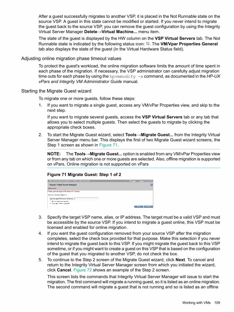
After a guest successfully migrates to another VSP, it is placed in the Not Runnable state on thesource VSP. A guest in this state cannot be modified or started. If you never intend to migratethe guest back to the source VSP, you can remove the guest configuration by using the IntegrityVirtual Server Manager Delete→Virtual Machine... menu item.The state of the guest is displayed by the HW column on the VSP Virtual Servers tab. The NotRunnable state is indicated by the following status icon: . The VM/Vpar Properties Generaltab also displays the state of the guest (in the Virtual Hardware Status field).
Adjusting online migration phase timeout valuesTo protect the guest's workload, the online migration software limits the amount of time spent ineach phase of the migration. If necessary, the VSP administrator can carefully adjust migrationtime outs for each phase by using the hpvmmodify -x command, as documented in the HP-UXvPars and Integrity VM Administrator Guide manual.
Starting the Migrate Guest wizardTo migrate one or more guests, follow these steps:1. If you want to migrate a single guest, access any VM/vPar Properties view, and skip to the
next step.If you want to migrate several guests, access the VSP Virtual Servers tab or any tab thatallows you to select multiple guests. Then select the guests to migrate by clicking theappropriate check boxes.
2. To start the Migrate Guest wizard, select Tools→Migrate Guest... from the Integrity VirtualServer Manager menu bar. This displays the first of two Migrate Guest wizard screens, theStep 1 screen as shown in Figure 71.
NOTE: The Tools→Migrate Guest... option is enabled from any VM/vPar Properties viewor from any tab on which one or more guests are selected. Also, offline migration is supportedon vPars. Online migration is not supported on vPars
Figure 71 Migrate Guest: Step 1 of 2
3. Specify the target VSP name, alias, or IP address. The target must be a valid VSP and mustbe accessible by the source VSP. If you intend to migrate a guest online, this VSP must belicensed and enabled for online migration.
4. If you want the guest configuration removed from your source VSP after the migrationcompletes, select the check box provided for that purpose. Make this selection if you neverintend to migrate the guest back to this VSP. If you might migrate the guest back to this VSPsometime, or if you might want to create a guest on this VSP that is based on the configurationof the guest that you migrated to another VSP, do not check the box.
5. To continue to the Step 2 screen of the Migrate Guest wizard, click Next. To cancel andreturn to the Integrity Virtual Server Manager screen from which you initiated the wizard,click Cancel. Figure 72 shows an example of the Step 2 screen.This screen lists the commands that Integrity Virtual Server Manager will issue to start themigration. The first command will migrate a running guest, so it is listed as an online migration.The second command will migrate a guest that is not running and so is listed as an offline
Working with VMs 109
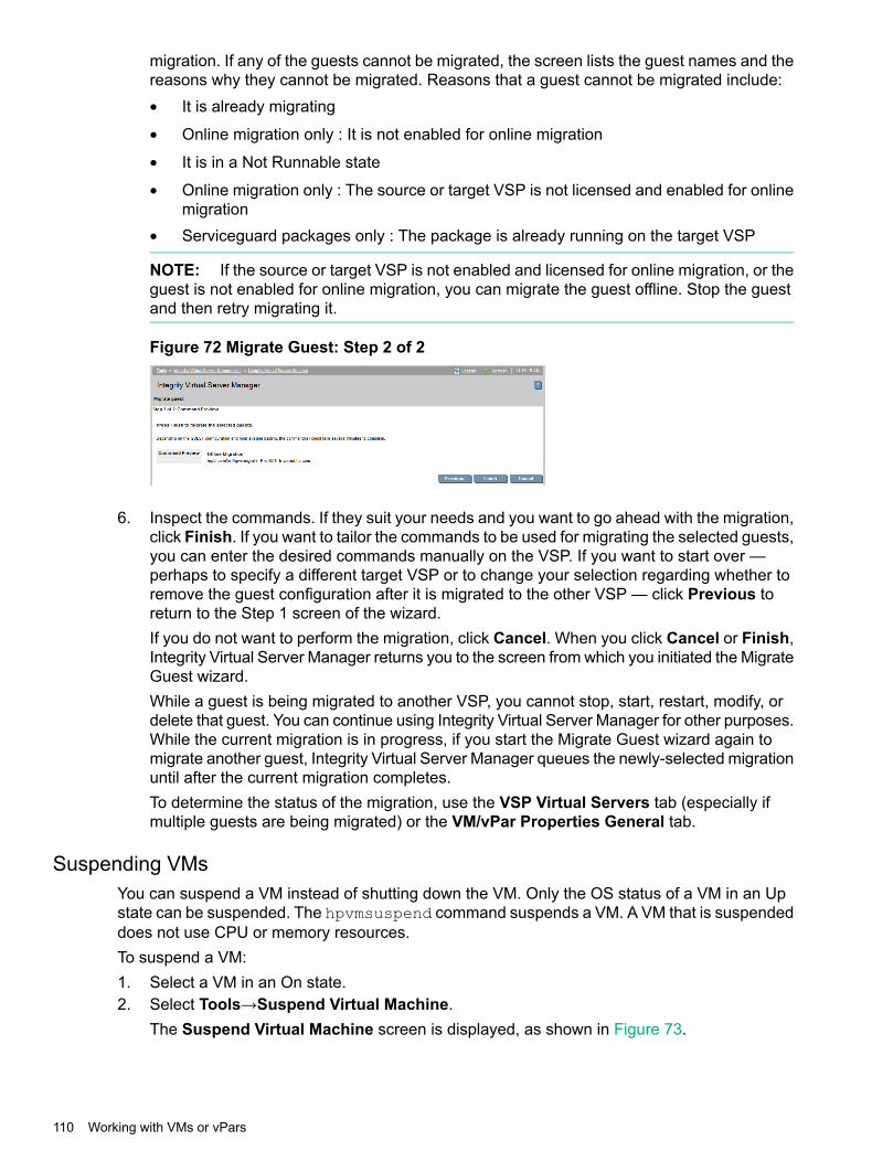
migration. If any of the guests cannot be migrated, the screen lists the guest names and thereasons why they cannot be migrated. Reasons that a guest cannot be migrated include:• It is already migrating
• Online migration only : It is not enabled for online migration
• It is in a Not Runnable state
• Online migration only : The source or target VSP is not licensed and enabled for onlinemigration
• Serviceguard packages only : The package is already running on the target VSP
NOTE: If the source or target VSP is not enabled and licensed for online migration, or theguest is not enabled for online migration, you can migrate the guest offline. Stop the guestand then retry migrating it.
Figure 72 Migrate Guest: Step 2 of 2
6. Inspect the commands. If they suit your needs and you want to go ahead with the migration,click Finish. If you want to tailor the commands to be used for migrating the selected guests,you can enter the desired commands manually on the VSP. If you want to start over —perhaps to specify a different target VSP or to change your selection regarding whether toremove the guest configuration after it is migrated to the other VSP — click Previous toreturn to the Step 1 screen of the wizard.If you do not want to perform the migration, click Cancel. When you click Cancel or Finish,Integrity Virtual Server Manager returns you to the screen from which you initiated the MigrateGuest wizard.While a guest is being migrated to another VSP, you cannot stop, start, restart, modify, ordelete that guest. You can continue using Integrity Virtual Server Manager for other purposes.While the current migration is in progress, if you start the Migrate Guest wizard again tomigrate another guest, Integrity Virtual Server Manager queues the newly-selected migrationuntil after the current migration completes.To determine the status of the migration, use the VSP Virtual Servers tab (especially ifmultiple guests are being migrated) or the VM/vPar Properties General tab.
Suspending VMsYou can suspend a VM instead of shutting down the VM. Only the OS status of a VM in an Upstate can be suspended. The hpvmsuspend command suspends a VM. A VM that is suspendeddoes not use CPU or memory resources.To suspend a VM:1. Select a VM in an On state.2. Select Tools→Suspend Virtual Machine.
The Suspend Virtual Machine screen is displayed, as shown in Figure 73.
110 Working with VMs or vPars

Figure 73 Virtual Machine Suspend
3. The Command Preview area shows the commands that Integrity VM performs to suspendthe VM.Click OK. The VM is suspended and the Virtual Servers tab is displayed. You can view thestatus as Sp in the OS column against the selected VM, as shown in Figure 74.
Figure 74 Suspend status
Resuming VMsA VM can be resumed only if it is in a suspended (SP) state. Resuming a VM saves time as itdoes not involve the actual shutdown and reboot of the OS.A VM is resumed by the hpvmresume command. The hyvmresume command checks whetherthe VM and its resources defined in the configuration file can be allocated. If it cannot be allocated,the VM is not resumed. Only superusers can execute the hpvmresume command.A VM cannot be resumed under the following conditions:
• VM is not in a suspended state.
• The server has fewer CPUs than the VM requires.
• The server has insufficient free memory.
• The server has insufficient CPU resources.
• The server has insufficient swap resources.
• Another VM is using a specified nonshared backing device.
• The server is using a specified backing device.
• A specified backing device does not exist.
• A specified vswitch is not available.
• The vswitch must be created using the hpvmnet command before the guests using it canbe resumed.
• The specified MAC address is in use.
• The specified guest is a distributed guest.To resume a VM:
Working with VMs 111
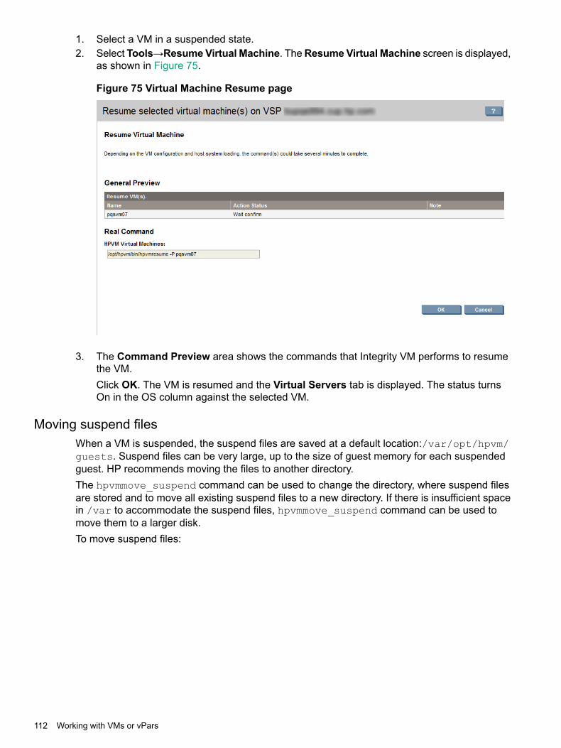
1. Select a VM in a suspended state.2. Select Tools→ResumeVirtual Machine. TheResumeVirtual Machine screen is displayed,
as shown in Figure 75.
Figure 75 Virtual Machine Resume page
3. The Command Preview area shows the commands that Integrity VM performs to resumethe VM.Click OK. The VM is resumed and the Virtual Servers tab is displayed. The status turnsOn in the OS column against the selected VM.
Moving suspend filesWhen a VM is suspended, the suspend files are saved at a default location:/var/opt/hpvm/guests. Suspend files can be very large, up to the size of guest memory for each suspendedguest. HP recommends moving the files to another directory.The hpvmmove_suspend command can be used to change the directory, where suspend filesare stored and to move all existing suspend files to a new directory. If there is insufficient spacein /var to accommodate the suspend files, hpvmmove_suspend command can be used tomove them to a larger disk.To move suspend files:
112 Working with VMs or vPars

1. Select Tools VM Move Suspend. The screen to specify the new directory is displayed, asshown in Figure 76
Figure 76 Virtual Machine move suspend
2. To change the default directly, select the Specified directory option and clickBrowse.The screen listing all the directories is displayed, as shown in Figure 77.
Figure 77 Virtual machine browse directory
3. Select a directory and click Select. The screen goes back to the VM Move Suspend page.4. The Command Preview field displays the specified directory location.
Click OK to move the suspended files to the specified directory.
Creating virtual switchesCreate Virtual Switch menu is applicable for both VMs and vPars. To provide network accessfor VMs or vPars, you must create virtual network switches (vswitches) for them. This sectiondescribes how to create a new vswitch on the VSP. The vswitch is used by a VM or vPar toconnect to the network: one or more VMs or vPars connect to the vswitch and the vswitch isconnected to a VSP's physical network device.
Working with VMs 113
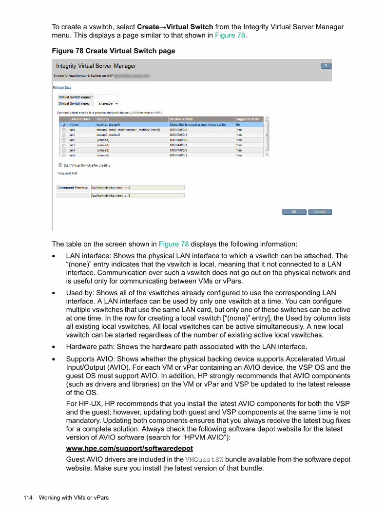
To create a vswitch, select Create→Virtual Switch from the Integrity Virtual Server Managermenu. This displays a page similar to that shown in Figure 78.
Figure 78 Create Virtual Switch page
The table on the screen shown in Figure 78 displays the following information:• LAN interface: Shows the physical LAN interface to which a vswitch can be attached. The
“(none)” entry indicates that the vswitch is local, meaning that it not connected to a LANinterface. Communication over such a vswitch does not go out on the physical network andis useful only for communicating between VMs or vPars.
• Used by: Shows all of the vswitches already configured to use the corresponding LANinterface. A LAN interface can be used by only one vswitch at a time. You can configuremultiple vswitches that use the same LAN card, but only one of these switches can be activeat one time. In the row for creating a local vswitch [“(none)” entry], the Used by column listsall existing local vswitches. All local vswitches can be active simultaneously. A new localvswitch can be started regardless of the number of existing active local vswitches.
• Hardware path: Shows the hardware path associated with the LAN interface.
• Supports AVIO: Shows whether the physical backing device supports Accelerated VirtualInput/Output (AVIO). For each VM or vPar containing an AVIO device, the VSP OS and theguest OS must support AVIO. In addition, HP strongly recommends that AVIO components(such as drivers and libraries) on the VM or vPar and VSP be updated to the latest releaseof the OS.For HP-UX, HP recommends that you install the latest AVIO components for both the VSPand the guest; however, updating both guest and VSP components at the same time is notmandatory. Updating both components ensures that you always receive the latest bug fixesfor a complete solution. Always check the following software depot website for the latestversion of AVIO software (search for “HPVM AVIO”):www.hpe.com/support/softwaredepotGuest AVIO drivers are included in the VMGuestSW bundle available from the software depotwebsite. Make sure you install the latest version of that bundle.
114 Working with VMs or vPars
With HP Integrity VM, AVIO requires a vswitch that has a physical network device as thebacking device (local vswitches such as localnet are not supported). In addition, the physicalNIC that backs the virtual switch must have an AVIO-compatible driver.For more information about AVIO requirements, see the HP Integrity Virtual Machinesdocumentation available at http://www.hpe.com/info/hpux-hpvm-docs.
Create the virtual switch by performing the following steps:1. (Required) Enter a virtual switch name.
• The name must be 8 characters or fewer.
• The allowable characters are A-Z, a-z, 0-9, dash (-), underscore (_), and period (.).
• The name cannot begin with a dash and cannot remain blank.2. Specify the virtual switch type (whether it is to be dedicated or shareable). The default is
shareable.
NOTE: The terms "shareable" and "dedicated" refer to how the switch is assigned to theVMs.• A dedicated vswitch can be used by only one started VM at a time and is dedicated to
providing network throughput to that VM. More than one VM can have the samededicated switch as a resource, but only one is allowed to start.
• A shareable vswitch can be used at any given time by all the associated VMs that containthe virtual network device (NIC) backed by a shareable vswitch.
NOTE: All VMs with virtual NICs backed by a shareable vswitch are not required tobe running. If you have a stopped VM that uses the shareable vswitch, you can alwaysstart the VM (unless other problems prevent it from starting).
3. (Required) From the table, select the VSP's physical network device that will be the physicalbacking of the vswitch.Choices include the following:• Any physical network cards (adapters) configured on the VSP
• Any APA (Automatic Port Aggregation) configured on the VSPThe display shows the APA name in one column and the individual devices or cards inthe next column; however, the letters "APA" do not appear in either column. In HP-UX,any LAN port with port number 900 or greater is an APA (for example, lan900 or lan901).
• NoneThis creates a local vswitch. When no physical network device on the VSP is chosen,the vswitch is a local vswitch. A local vswitch has no connection with any physicalnetwork device on the VSP. VM virtual network interface cards (vNICs) can communicateonly with other VMs on the same VSP that are connected to the same local vswitch.
4. Specify whether or not to start the vswitch after it is created. The default is to start the vswitch.Clicking OK does the following:• Creates the new vswitch, using the hpvmnet command.
• If you chose to make the vswitch dedicated, configures the vswitch as a dedicated vswitch,using the hpvmdevmgmt command.
• If you chose to have the switch started, starts the vswitch, using the hpvmnet command.A preview of these commands is shown in the Command Preview area. After you click OK, anyerrors that occur with the execution of these commands is displayed on a separate error page
Working with VMs 115
that lists each command and whether the command succeeded, failed, or was not attempted.Clicking OK on the error page returns you to the Create Vswitch page.
Starting, stopping, and deleting virtual switchesTo start or stop a virtual switch, select Tools→Start Virtual Switch... or Tools→Stop VirtualSwitch... from the Integrity Virtual Server Manager menu bar. To delete a virtual switch, selectDelete→Virtual Switch.... Access these menu options from a view that allows you to select oneor more virtual switches, such as the VSP Virtual Switches tab. In this way, you can act onseveral multiple switches simultaneously, if selected. (You can also access the menu optionsfrom the Vswitch Properties view, in which case the action is performed on a single virtual switch:the one being viewed.)To start a vswitch, select Tools→Start Virtual Switch.... Once a vswitch is started, the VMs thatare connected to it can use it for network connectivity. Before you start a vswitch, it must bestopped.To stop a vswitch, select Tools→Stop Virtual Switch.... The selected vswitch must currentlybe started. Once a vswitch is stopped, the VMs connected to it can no longer use it for networkconnectivity.To remove all configuration information for a vswitch, select Delete→Virtual Switch.... Beforeyou remove a vswitch, you must first stop it.
NOTE: For information about creating and managing vswitches, see the HP-UX vPars andIntegrity VM Administrator Guide available at http://www.hpe.com/info/hpux-hpvm-docs.
Deleting network or storage devicesDelete Network or Storage Device menu is applicable to both VMs and vPars. To delete anetwork or storage device from a VM or vPar, select one or more I/O devices from a Networkor Storage tab, and then select Delete→I/O Device... from the Integrity Virtual Server Managermenu bar. You can select I/O devices from any of the following tabs: VSP Storage, VM or vParProperties Storage, VSP Network, VM or vPar Properties Network, Vswitch PropertiesNetwork.Selecting Delete→I/O Device... displays a page that allows you to remove the selected I/Odevices.When you delete a device from a VM or vPar, it is disassociated from that VM or vPar, allowingthe device to be used by another VM or vPar on the VSP. Deleted devices remain active on aVM or vPar that is running; the devices are removed once you restart the VM or vPar.Storage devices that you can delete include virtual disks and DVDs as well as attached tapes,burners, and changers. Deleting a storage device does not affect data on that device (files ordata are not removed from the device).
116 Working with VMs or vPars

NOTE: You cannot remove a device that is currently being used by the guest OS or if I/O isoutstanding.If a VM or vPar is running HP-UX, devices selected for removal might not be removed until yourestart the VM or vPar. To confirm that the device has been removed from the VM or vPar, viewthe appropriate Network or Storage tab.
NOTE: If the VM or vPar is powered on, preliminary actions might be required to remove anAVIO storage device. If the VM or vPar is powered off, no preliminary actions are required toremove the AVIO storage device (or any other selected storage device). To remove an AVIOstorage device from a VM or vPar that is powered on, note the following:• If the VM or vPar is powered on and running at EFI, to remove the device, first stop the VM
or vPar. To stop the VM or vPar, use the Integrity Virtual Server Manager Tools→Stop VMor vPar... menu option. Once the VM or vPar has stopped, delete the device using theDelete→I/O Device... menu option.
• If the VM or vPar is powered on and running HP-UX 11i v3, you must remove all instancesof the device from the guest OS. To do so, follow these steps:1. Obtain the device's hardware target path (tgtpath class) or lun path (lunpath class),
using the ioscan command at the guest in either of the following ways:ioscan -kfNC tgtpath
orioscan -kfNC lunpath
2. Remove the device by using the rmsf command at the guest, specifying the obtainedhardware path:rmsf -H tgtpath
orrmsf -H lunpath
Once the device has been completely removed from the guest OS, then you can deletethe storage device by using the Integrity Virtual Server Manager Delete→I/O Device...menu option.
NOTE: HP Integrity VM maintains a device database that includes entries for all devices andtheir associations. If deleting a device causes removal of the last association of that device withany other VM or vPar on the VSP, HP Integrity VM removes that device from its device databaseunless it is marked for preservation. To preserve an entry, use the Integrity VM hpvmdevmgmtcommand, specifying PRESERVE=YES; or, when creating a file as a backing device, specify the-S) and -A attributes with that command.When you use Integrity Virtual Server Manager to create a file as a backing device for a disk,the PRESERVE attribute is set as PRESERVE=YES.
Opening iLO consoleThe virtual console is a terminal from which you can manage all the VMs or vPars within VSP.To start the virtual console terminal of a VM or a vPar:1. Click the Virtual Servers tab.
The VMs or vPars are listed in this tab.
2. Select one or more VMs or vPars by selecting the check box against each required VM orvPar.
Working with VMs 117

3. Select Tools→Open iLO Console or Open Virtual iLO Remote Console from the VirtualServers menu bar.The iLO Console screen is displayed.
Figure 79 iLO console
The Main menu is listed:• CO: Console
• CM: Command Menu
• CL: Console Log
• SL: Show Event Log
• VM: VM Menu
• HE: Main Help Menu
• X: Exit Connection
Opening virtual iLO remote consoleThe remote console is a terminal to manage a VM or vPar. This feature allows you to access theguest directly. You do not have to run the hpvmconsole command to search for the host machineand guest name. An IP address is assigned to each VM or vPar. You can use this unique IPaddress and the host login credentials to directly access the guest without running any additionalcommands.You can use the remote console when you want to access a specific VM or vPar. The logincredentials are the same as the credentials that are configured during the OS installation on theVM or vPar.You can configure the parameters for the virtual iLO remote console from the Modify menu. Toadd a virtual iLO console or to modify the parameters of an existing virtual iLO console, selectModify→Add/Modify Virtual iLO Remote Console... to open the Add/Modify Virtual iLORemote Console page. For more information, see the Add/Modify Virtual iLO Remote Consolehelp topic.
NOTE: You can also configure remote console using the hpvm commands on the VMMgr CLI.
118 Working with VMs or vPars
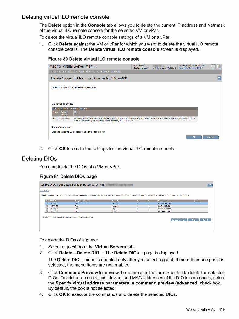
Deleting virtual iLO remote consoleThe Delete option in the Console tab allows you to delete the current IP address and Netmaskof the virtual iLO remote console for the selected VM or vPar.To delete the virtual iLO remote console settings of a VM or a vPar:1. Click Delete against the VM or vPar for which you want to delete the virtual iLO remote
console details. The Delete virtual iLO remote console screen is displayed.
Figure 80 Delete virtual iLO remote console
2. Click OK to delete the settings for the virtual iLO remote console.
Deleting DIOsYou can delete the DIOs of a VM or vPar.
Figure 81 Delete DIOs page
To delete the DIOs of a guest:1. Select a guest from the Virtual Servers tab.2. Click Delete→Delete DIO.... The Delete DIOs... page is displayed.
The Delete DIO... menu is enabled only after you select a guest. If more than one guest isselected, the menu items are not enabled.
3. ClickCommand Preview to preview the commands that are executed to delete the selectedDIOs. To add parameters, bus, device, and MAC addresses of the DIO in commands, selectthe Specify virtual address parameters in command preview (advanced) check box.By default, the box is not selected.
4. Click OK to execute the commands and delete the selected DIOs.
Working with VMs 119

Adding DIOsYou can add DIOs to a VM or vPar.
Figure 82 Add DIOs to VM or vPar page
To add DIOs:1. Select a guest from the Virtual Servers tab.2. Click Modify→ Add DIO. The Add DIOs to (VM or vPar) page is displayed.
The Add DIO menu is enabled only after you select a guest. If more than one guest isselected, the menu items are not enabled.
3. Select DIOs from the HPVM DIO table. To specify the PCI bus number, PCI device number,and MAC address, select the Specify virtual address parameters (advanced) check box.When you select the check box, fields to enter BUS, Device, and MAC address are displayed.If you do not enter any value in the fields, the default values are applied.
NOTE: PCI bus number must be from 0 through 7.PCI device number must be from 0 through 7.MAC address format must be 0x000000000000. It must begin with 0x followed by 12hexadecimal characters.
NOTE: PCI bus and PCI device number must exist together. If one number is enteredwithout the other, the following error message is displayed when you click CommandPreview.The DIO with backing DIO function x/x/x/x/x/x/x has a missing adaptervalue (bus a, device (default)). Enter both of the adapter arguments(bus, device) or remove both of them.
The Command Preview field also displays a note that there are errors in the input.MAC address can exist separately without the PCI bus and device numbers.
4. Click OK to add the DIO to the guest.
Replacing DIO H/W pathYou can replace the h/w path of a DIO owned by a VM or vPar.
120 Working with VMs or vPars
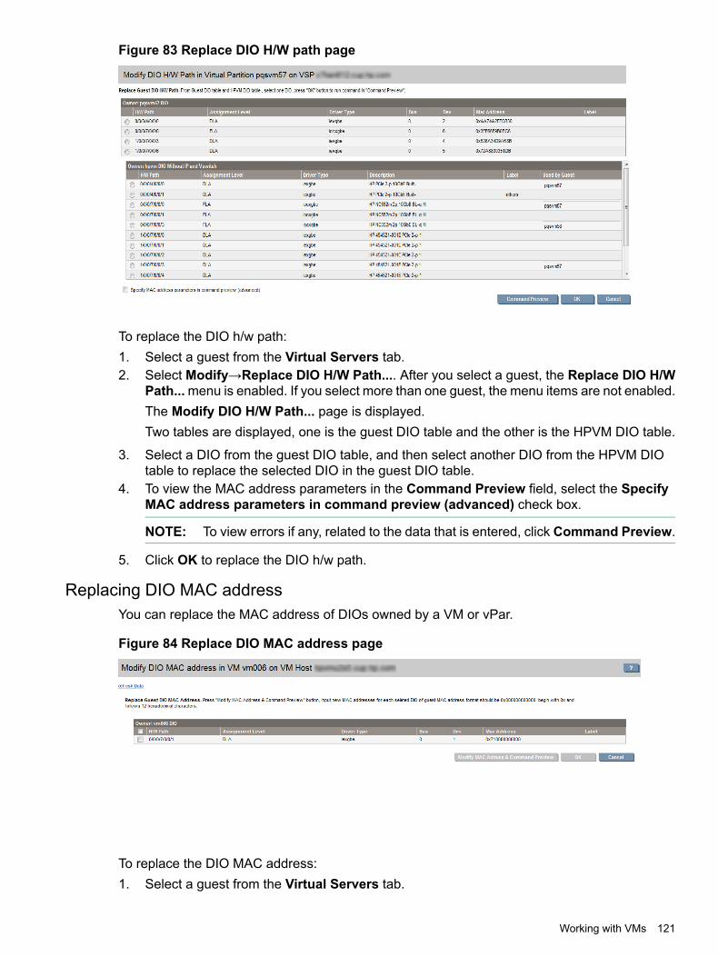
Figure 83 Replace DIO H/W path page
To replace the DIO h/w path:1. Select a guest from the Virtual Servers tab.2. Select Modify→Replace DIO H/W Path.... After you select a guest, the Replace DIO H/W
Path...menu is enabled. If you select more than one guest, the menu items are not enabled.The Modify DIO H/W Path... page is displayed.Two tables are displayed, one is the guest DIO table and the other is the HPVM DIO table.
3. Select a DIO from the guest DIO table, and then select another DIO from the HPVM DIOtable to replace the selected DIO in the guest DIO table.
4. To view the MAC address parameters in the Command Preview field, select the SpecifyMAC address parameters in command preview (advanced) check box.
NOTE: To view errors if any, related to the data that is entered, click Command Preview.
5. Click OK to replace the DIO h/w path.
Replacing DIO MAC addressYou can replace the MAC address of DIOs owned by a VM or vPar.
Figure 84 Replace DIO MAC address page
To replace the DIO MAC address:1. Select a guest from the Virtual Servers tab.
Working with VMs 121

2. Click Modify→Replace DIO MAC Address.... The Modify DIO MAC address page isdisplayed.The Replace DIO MAC Address... menu is enabled only after you select a guest. If youselect more than one guest, the menu items are not enabled.
3. Select DIOs in the guest DIO table.4. Click Modify MAC Address & Command Preview, and then enter the new MAC address
in the new table that is displayed.
NOTE: To view errors if any, related to the data that is entered, clickModify MACAddress& Command Preview.
5. Click OK to save the modified DIO MAC address.
Working with vParsCreating vPars
To create a vPar, Virtual Server Manager uses the Create Virtual Partition wizard to guide youthrough the process. Each steps presents a dialog that allows you to specify the requiredinformation. At any time you can get help, return to previous steps, or exit the wizard. By creatinga new vPar, you assign attributes and resources to it. This creates an association among thevirtual devices known to vPar and the physical devices managed by the vPar VSP.To access the Create Virtual Partition wizard, select Create→Virtual Partition from the vParsmenu bar. The Create Virtual Partition wizard leads you through several screens in the followingorder. For more information about any screen, see the corresponding Virtual Server Managerhelp topic.1. Specify vPar Identity
Specify the vPar name and an optional description.
2. Specify Processor CountSpecify the number of CPUs.
3. Specify MemorySpecify the amount of base and float memory (optional) designated for the vPar.
4. Specify Network DevicesTo add a virtual network device, click Add Network Device... on the first network devicescreen. This displays theAddNetwork Device screen. First, select the type of virtual networkinterface card. The default card type is AVIO LAN (the choices depend on the version of theHP-UX installed on the VSP). AVIO LAN supports newly attached devices on HP-UX 11i v2and HP-UX 11i v3 vPars.After you select the virtual network interface type, select the virtual switch from the listprovided or create a virtual switch. To provide network access for the vPar, a virtual switchis necessary.Select the Specify virtual network interface card parameters (advanced) check box tomanually specify virtual network interface card parameters. This is an advanced option. Bydefault, virtual interface card parameters are numbered automatically during vPar creation,but they can be specified manually when this option is selected. HP recommends acceptingthe automatically numbered parameters that Virtual Server Manager provides. When manuallyspecifying virtual network interface card parameters, valid bus numbers are 0 to 6, and validdevice numbers are 0 to 7. You must either specify values for both numbers or leave bothblank.
122 Working with VMs or vPars

5. Specify DIOsYou can add DIOs to a vPar to provide near native I/O functionality, manageability, andperformance by giving a vPar direct access to Host PCI Express (PCIe) functions, whichmay be physical or virtual.To add DIOs:1. Click Add DIO.... The Add a DIO to vPar... screen is displayed.2. Select the preferred DIOs from the HPVM DIO table. These DIOs do not have an IP
address and are not associated with a Vswitch.3. If you want to enter the Bus, Device, and MAC parameters for the selected DIOs, select
Specify virtual address parameters (advanced). If you want to use the defaultparameters, leave the check box blank.
4. Click Add to List to add the selected DIOs to the vPar. The Specify DIOs page isdisplayed, where the selected DIOs are listed.
5. Click Next to move to the next screen of the wizard.To delete a DIO, select the DIO from the list in the wizard view, and then click Delete.
NOTE: If you want to modify a DIO, you must first delete it and then add the device againwith the correct specifications.
Table 16 (page 123) describes the information which the device selection table displays.
Table 16 DIO selection table: column descriptions
DescriptionParameter name
The H/W Path indicates the functions of a device. Forexample, a function H/W path 0/0/0/3/0/0/0 indicatesfunction 0, which is the last number of the H/W path.Therefore, 0/0/0/3/0/0/[0–N] are all functions of thesame device 0/0/0/3/0/0.
H/W Path
Indicates whether the operation of the DIO is at afunction level or device level. In Function LevelAssignment (FLA), each function is shared amongseveral VMs or vPars. In Device Level Assignment(DLA), an entire device is assigned to the same guestOS. In the DIO pool, all functions of DIOs withdevice-level assignment are placed together. If acommand is issued to one function in the device, allother functions also perform the same operation. Forexample, 0/0/0/4/0/0/0 and 0/0/0/4/0/0/1 aredevice-level functions and belong to the device,0/0/0/4/0/0. They are placed in a single cell in the DIOpool. If you select them from the host or HPVM table,the command preview field displays only the firstfunction, 0/0/0/4/0/0/0.
Assignment Level
Indicates the type of DIO driver. The driver used mustbe compatible with DIO. For example, HPUX 11i v31112/1203 iexgbe guest driver with DIO support.
Driver Type
Displays a description of the DIO network adaptor. Forexample, AM225-60001 HP Integrity PCIe 2-port10GbE-SR Fabric Adapter.
Description
Indicates the label of the DIO.Label
Indicates the VMs or vPars configured to use this DIO.Used by Guest
6. Specify storage deviceYou specify virtual adapter cards for the vPar. The virtual storage adapter cards areassociated with the virtual storage devices that are backed by physical storage. A physical
Working with vPars 123

storage device can be a disk, DVD, tape, and Media Changer. NPIV is a Fiber Channelfacility allowing multiple N_Port IDs to share a single N_Port. To add a virtual storage device,click Add Storage Device.... This displays the Add Storage Device screen. First, selectthe type of virtual storage adapter. The default adapter type is AVIO storage. AVIO storagesupports new attached devices on HP-UX 11i v2 and HP-UX 11i v3 vPars. The attacheddevices configured using AVIO (avio_stor adapter), have the following benefits over attacheddevices configured with VIO (scsi adapter):1. Allow sharing of tapes, changers, and burners among multiple vPars and VSPs2. Support of USB 2.0 DVD burners3. Improved performanceIf the VSP is running HP-UX 11i v3, the Add Storage Device screen gives you the choiceof listing storage devices by their agile address (the default) or by their legacy address. HPrecommends using agile device addressing when configuring storage devices. This providesbenefits especially for multipath devices. With legacy addressing, the screen lists one entryfor each path to a storage device that has multiple paths. With agile addressing, the screenlists only one entry for each multipath storage device. To change the addressing schemefor viewing, select the appropriate addressing scheme.After you select the virtual storage adapter type, select the physical backing device from thelist of devices provided in the device selection table.
NOTE: Any devices added using the Create Virtual Partition wizard are not functional onthe vPar until the new vPar is started. Certain devices are not seen in a Virtual ServerManager Storage tab until the vPar is started.
7. SummaryReview the identity and resources specified for the new vPar and preview the command thatwill be used to create the new vPar. This summary step allows you to review all the informationbefore the new vPar is created.At this step, you can still cancel (exit the Create Virtual Partition wizard) or return to modifyprevious steps in the wizard. When you click Finish, the wizard executes the vparcreatecommands displayed in the Command Preview area.
124 Working with VMs or vPars

8. Next Steps for vParsAfter creating the new vPar, Integrity Virtual Server Manager presents you with the nextsteps you can take to manage and use the new vPar. The steps presented depend on theenvironment in which you created the vPar. For example, when vPar scheduling on a VSPis managed by Global Workload Manager (gWLM), the Next Steps page advises you toassociate the vPar with a gWLM policy and add the vPar to a Shared Resource Domain(SRD). You cannot start the vPar until you complete that action.If the new vPar includes AVIO devices (AVIO support is provided on HP Integrity vPar Version3.5 or later), you are advised to make sure the appropriate OS that supports AVIO is installedon the VSP and the vPar. If the intended OS on the vPar does not support AVIO, you arewarned of this. In addition, HP strongly recommends that AVIO components (such as driversand libraries) on the vPar and VSP be updated to the latest release of the OS. For moreinformation about AVIO requirements, see the HP-UX vPars and Integrity VM AdministratorGuide manual.Other steps you can take include starting the virtual hardware for the vPar, accessing thevPar console, adding additional software (provider components) needed to supportmanagement of the vPar, getting information about the vPar, and tuning the performanceof the vPar.
NOTE: Any devices added using the Create Virtual Partition wizard are not functional onthe vPar until the new vPar is started. Certain devices are not seen in a Integrity VirtualServer Manager Storage tab until the vPar is started.
You can configure the vPar's Extensible Firmware Interface (EFI) to boot the guest OSautomatically when the vPar is started (powered on). Configure EFI when the vPar has beenstarted and before booting the OS. You can interact with EFI through the virtual ManagementProcessor (vMP) for the vPar. The vMP provides access to the console for the vPar. Tointeract with vMP, use the hpvmconsole command. For more information, see the HP-UXvPars and Integrity VM Administrator Guide manual.If you are using Integrity Virtual Server Manager from HP SMH, click OK to finish. IntegrityVirtual Server Manager displays the page from which you initiated the Create Virtual Partitionwizard.If you are using Integrity Virtual Server Manager from HP Matrix Operating Environment,click Apply gWLM Policy. To skip this step and add the new vPar to the SRD later, clickApply Later (you must click either button). When you click Apply Later, Integrity VirtualServer Manager displays the page from which you initiated the Create Virtual Partition wizard.When you are ready to add the vPar to the SRD, select the vPar from the appropriate screen(for example, from the VSP Virtual Servers tab) and then select Policy →Apply gWLMPolicy ... from the Integrity Virtual Server Manager menu bar. For more information, see theIntegrity Virtual Server Manager Policy Menu help topic.
NOTE: After creating a vPar using Integrity Virtual Server Manager, if you returnimmediately to HP Matrix OE visualization, the machine might not yet appear in HP MatrixOE visualization. This means Systems Insight Manager/HP Matrix Operating Environmenthas not yet completed identifying the new vPar. However, it appears when the identificationprocess completes (usually within a minute or two).
Modifying vParsTo modify a vPar, select one of the following items from the Virtual Server Manager Modifymenu. For more information about any item, see the corresponding Virtual Server Manager helptopic.
NOTE: You can modify only one vPar at a time.
Working with vPars 125
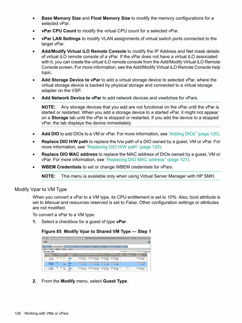
• Base Memory Size and Float Memory Size to modify the memory configurations for aselected vPar.
• vPar CPU Count to modify the virtual CPU count for a selected vPar.
• vPar LAN Settings to modify VLAN assignments of virtual switch ports connected to thetarget vPar.
• Add/Modify Virtual iLO Remote Console to modify the IP Address and Net mask detailsof virtual iLO remote console of a vPar. If the vPar does not have a virtual iLO associatedwith it, you can create the virtual iLO remote console from the Add/Modify Virtual iLO RemoteConsole screen. For more information, see the Add/Modify Virtual iLO Remote Console helptopic.
• Add Storage Device to vPar to add a virtual storage device to selected vPar, where thevirtual storage device is backed by physical storage and connected to a virtual storageadapter on the VSP.
• Add Network Device to vPar to add network devices and vswitches for vPars.
NOTE: Any storage devices that you add are not functional on the vPar until the vPar isstarted or restarted. When you add a storage device to a started vPar, it might not appearon a Storage tab until the vPar is stopped or restarted. If you add the device to a stoppedvPar, the tab displays the device immediately.
• Add DIO to add DIOs to a VM or vPar. For more information, see “Adding DIOs” (page 120).
• Replace DIO H/W path to replace the h/w path of a DIO owned by a guest, VM or vPar. Formore information, see “Replacing DIO H/W path” (page 120).
• Replace DIO MAC address to replace the MAC address of DIOs owned by a guest, VM orvPar. For more information, see “Replacing DIO MAC address” (page 121).
• WBEM Credentials to set or change WBEM credentials for vPars.
NOTE: This menu is available only when using Virtual Server Manager with HP SMH.
Modify Vpar to VM TypeWhen you convert a vPar to a VM type, its CPU entitlement is set to 10%. Also, boot attribute isset to Manual and resources reserved is set to False. Other configuration settings or attributesare not modified.To convert a vPar to a VM type:1. Select a checkbox for a guest of type vPar.
Figure 85 Modify Vpar to Shared VM Type — Step 1
2. From the Modify menu, select Guest Type.
126 Working with VMs or vPars
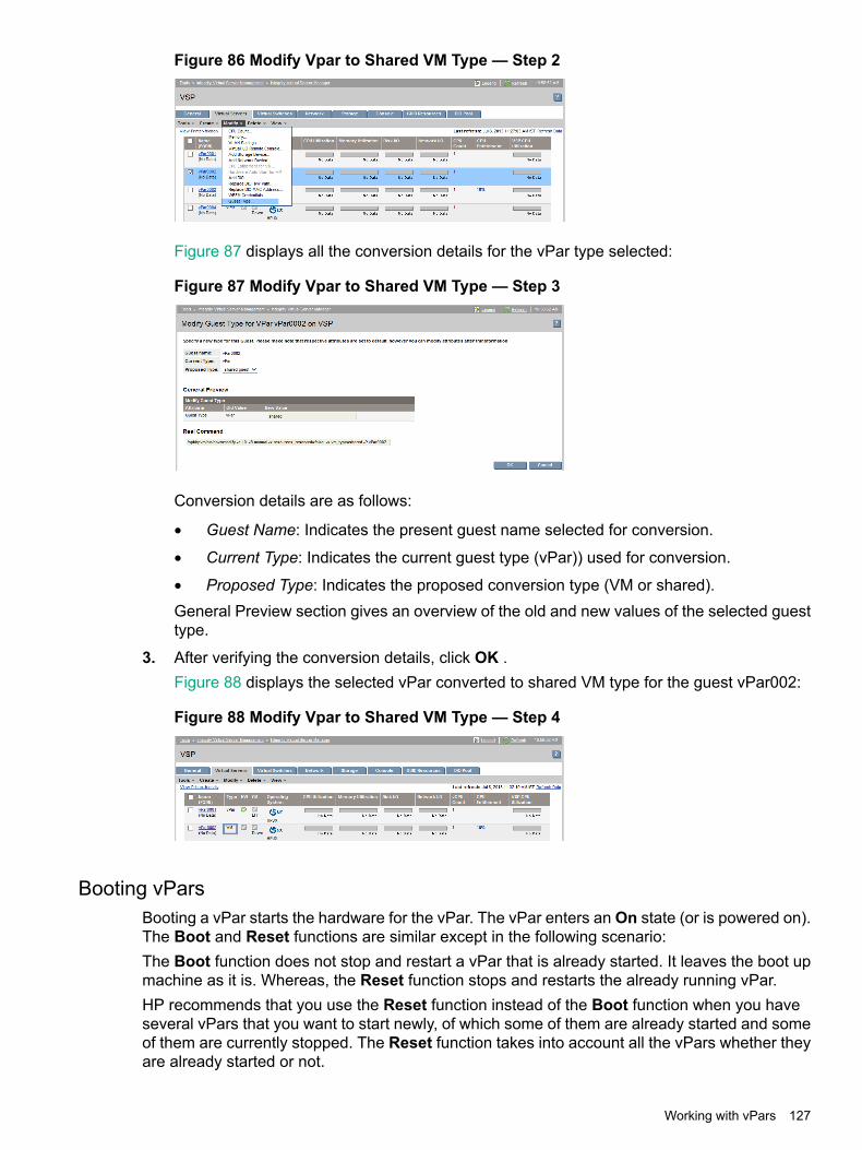
Figure 86 Modify Vpar to Shared VM Type — Step 2
Figure 87 displays all the conversion details for the vPar type selected:
Figure 87 Modify Vpar to Shared VM Type — Step 3
Conversion details are as follows:
• Guest Name: Indicates the present guest name selected for conversion.
• Current Type: Indicates the current guest type (vPar)) used for conversion.
• Proposed Type: Indicates the proposed conversion type (VM or shared).General Preview section gives an overview of the old and new values of the selected guesttype.
3. After verifying the conversion details, click OK .Figure 88 displays the selected vPar converted to shared VM type for the guest vPar002:
Figure 88 Modify Vpar to Shared VM Type — Step 4
Booting vParsBooting a vPar starts the hardware for the vPar. The vPar enters an On state (or is powered on).The Boot and Reset functions are similar except in the following scenario:The Boot function does not stop and restart a vPar that is already started. It leaves the boot upmachine as it is. Whereas, the Reset function stops and restarts the already running vPar.HP recommends that you use the Reset function instead of the Boot function when you haveseveral vPars that you want to start newly, of which some of them are already started and someof them are currently stopped. The Reset function takes into account all the vPars whether theyare already started or not.
Working with vPars 127
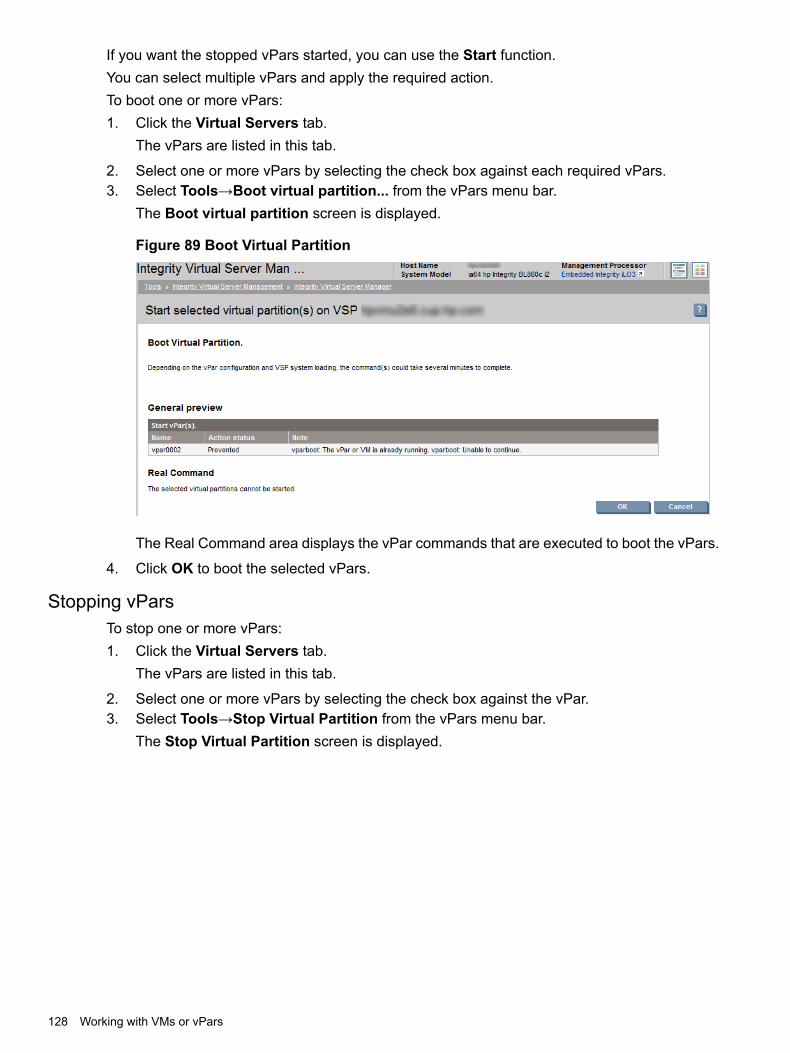
If you want the stopped vPars started, you can use the Start function.You can select multiple vPars and apply the required action.To boot one or more vPars:1. Click the Virtual Servers tab.
The vPars are listed in this tab.
2. Select one or more vPars by selecting the check box against each required vPars.3. Select Tools→Boot virtual partition... from the vPars menu bar.
The Boot virtual partition screen is displayed.
Figure 89 Boot Virtual Partition
The Real Command area displays the vPar commands that are executed to boot the vPars.
4. Click OK to boot the selected vPars.
Stopping vParsTo stop one or more vPars:1. Click the Virtual Servers tab.
The vPars are listed in this tab.
2. Select one or more vPars by selecting the check box against the vPar.3. Select Tools→Stop Virtual Partition from the vPars menu bar.
The Stop Virtual Partition screen is displayed.
128 Working with VMs or vPars
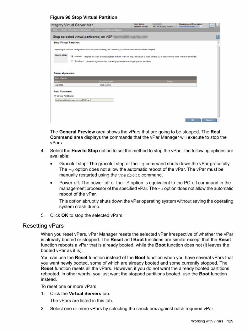
Figure 90 Stop Virtual Partition
The General Preview area shows the vPars that are going to be stopped. The RealCommand area displays the commands that the vPar Manager will execute to stop thevPars.
4. Select the How to Stop option to set the method to stop the vPar. The following options areavailable:• Graceful stop: The graceful stop or the -g command shuts down the vPar gracefully.
The -g option does not allow the automatic reboot of the vPar. The vPar must bemanually restarted using the vparboot command.
• Power-off: The power-off or the -d option is equivalent to the PC-off command in themanagement processor of the specified vPar. The -d option does not allow the automaticreboot of the vPar.This option abruptly shuts down the vPar operating system without saving the operatingsystem crash dump.
5. Click OK to stop the selected vPars.
Resetting vParsWhen you reset vPars, vPar Manager resets the selected vPar irrespective of whether the vParis already booted or stopped. The Reset and Boot functions are similar except that the Resetfunction reboots a vPar that is already booted, while the Boot function does not (it leaves thebooted vPar as it is).You can use the Reset function instead of the Boot function when you have several vPars thatyou want newly booted, some of which are already booted and some currently stopped. TheReset function resets all the vPars. However, if you do not want the already booted partitionsrebooted, in other words, you just want the stopped partitions booted, use the Boot functioninstead.To reset one or more vPars:1. Click the Virtual Servers tab.
The vPars are listed in this tab.
2. Select one or more vPars by selecting the check box against each required vPar.
Working with vPars 129
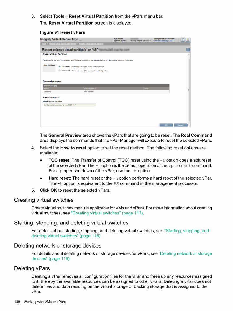
3. Select Tools→Reset Virtual Partition from the vPars menu bar.The Reset Virtual Partition screen is displayed.
Figure 91 Reset vPars
TheGeneral Preview area shows the vPars that are going to be reset. TheReal Commandarea displays the commands that the vPar Manager will execute to reset the selected vPars.
4. Select the How to reset option to set the reset method. The following reset options areavailable:• TOC reset: The Transfer of Control (TOC) reset using the -t option does a soft reset
of the selected vPar. The -t option is the default operation of the vparreset command.For a proper shutdown of the vPar, use the -h option.
• Hard reset: The hard reset or the -h option performs a hard reset of the selected vPar.The -h option is equivalent to the RS command in the management processor.
5. Click OK to reset the selected vPars.
Creating virtual switchesCreate virtual switches menu is applicable for VMs and vPars. For more information about creatingvirtual switches, see “Creating virtual switches” (page 113).
Starting, stopping, and deleting virtual switchesFor details about starting, stopping, and deleting virtual switches, see “Starting, stopping, anddeleting virtual switches” (page 116).
Deleting network or storage devicesFor details about deleting network or storage devices for vPars, see “Deleting network or storagedevices” (page 116).
Deleting vParsDeleting a vPar removes all configuration files for the vPar and frees up any resources assignedto it, thereby the available resources can be assigned to other vPars. Deleting a vPar does notdelete files and data residing on the virtual storage or backing storage that is assigned to thevPar.
130 Working with VMs or vPars

NOTE: Before you remove a vPar, you must stop the vPar or put to Off state (powered off).
By default, vswitch VLAN port assignments are removed when the vPar is deleted. If any of theports are connected to other vPars that are not removed, those port assignments are not removed.Clearing the Remove VLAN Assignment check box causes vswitch VLAN port assignments toremain after the vPar is deleted.To remove one or more vPars:1. Select one or more vPars from the Virtual Servers tab.2. Select Delete→Delete Virtual Partition. The Delete Virtual Partition screen is displayed.
Figure 92 Delete virtual partition
3. Click OK to delete the selected vPars.
Opening iLO consoleFor details about opening iLO console, see “Opening iLO console” (page 117).
Opening virtual iLO remote consoleFor details about opening virtual iLO remote console, see “Opening virtual iLO remote console”(page 118).
Deleting virtual iLO remote consoleFor details about deleting virtual iLO remote console, see “Deleting virtual iLO remote console”(page 119).
Adding DIOsFor details about the adding DIOs, see “Adding DIOs” (page 120).
Replacing DIO H/W pathFor details about replacing H/W paths, see “Replacing DIO H/W path” (page 120).
Replacing DIO MAC addressFor details about replacing DIO MAC addresses, see “Replacing DIO MAC address” (page 121).
Deleting DIOsFor details about deleting DIOs, see “Deleting DIOs” (page 119).
Working with vPars 131

132
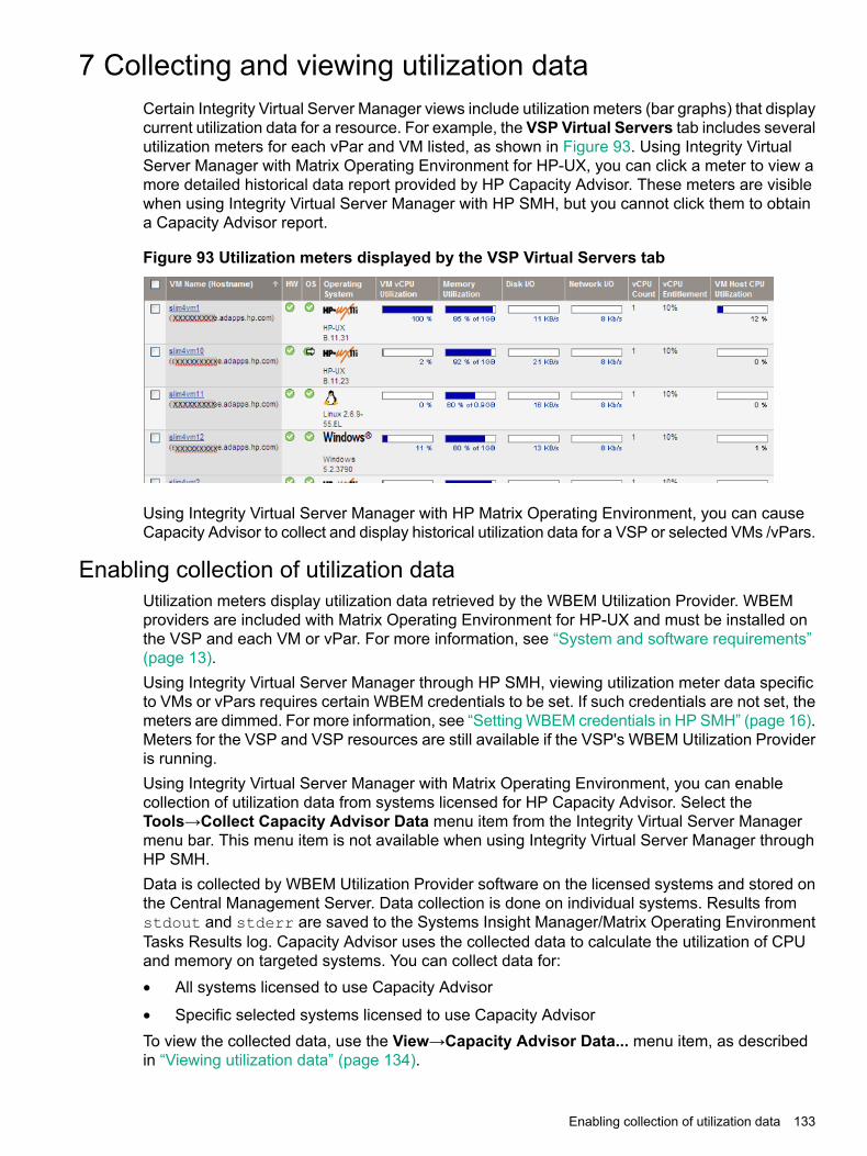
7 Collecting and viewing utilization dataCertain Integrity Virtual Server Manager views include utilization meters (bar graphs) that displaycurrent utilization data for a resource. For example, the VSP Virtual Servers tab includes severalutilization meters for each vPar and VM listed, as shown in Figure 93. Using Integrity VirtualServer Manager with Matrix Operating Environment for HP-UX, you can click a meter to view amore detailed historical data report provided by HP Capacity Advisor. These meters are visiblewhen using Integrity Virtual Server Manager with HP SMH, but you cannot click them to obtaina Capacity Advisor report.
Figure 93 Utilization meters displayed by the VSP Virtual Servers tab
Using Integrity Virtual Server Manager with HP Matrix Operating Environment, you can causeCapacity Advisor to collect and display historical utilization data for a VSP or selected VMs /vPars.
Enabling collection of utilization dataUtilization meters display utilization data retrieved by the WBEM Utilization Provider. WBEMproviders are included with Matrix Operating Environment for HP-UX and must be installed onthe VSP and each VM or vPar. For more information, see “System and software requirements”(page 13).Using Integrity Virtual Server Manager through HP SMH, viewing utilization meter data specificto VMs or vPars requires certain WBEM credentials to be set. If such credentials are not set, themeters are dimmed. For more information, see “Setting WBEM credentials in HP SMH” (page 16).Meters for the VSP and VSP resources are still available if the VSP's WBEM Utilization Provideris running.Using Integrity Virtual Server Manager with Matrix Operating Environment, you can enablecollection of utilization data from systems licensed for HP Capacity Advisor. Select theTools→Collect Capacity Advisor Data menu item from the Integrity Virtual Server Managermenu bar. This menu item is not available when using Integrity Virtual Server Manager throughHP SMH.Data is collected by WBEM Utilization Provider software on the licensed systems and stored onthe Central Management Server. Data collection is done on individual systems. Results fromstdout and stderr are saved to the Systems Insight Manager/Matrix Operating EnvironmentTasks Results log. Capacity Advisor uses the collected data to calculate the utilization of CPUand memory on targeted systems. You can collect data for:• All systems licensed to use Capacity Advisor
• Specific selected systems licensed to use Capacity AdvisorTo view the collected data, use the View→Capacity Advisor Data... menu item, as describedin “Viewing utilization data” (page 134).
Enabling collection of utilization data 133
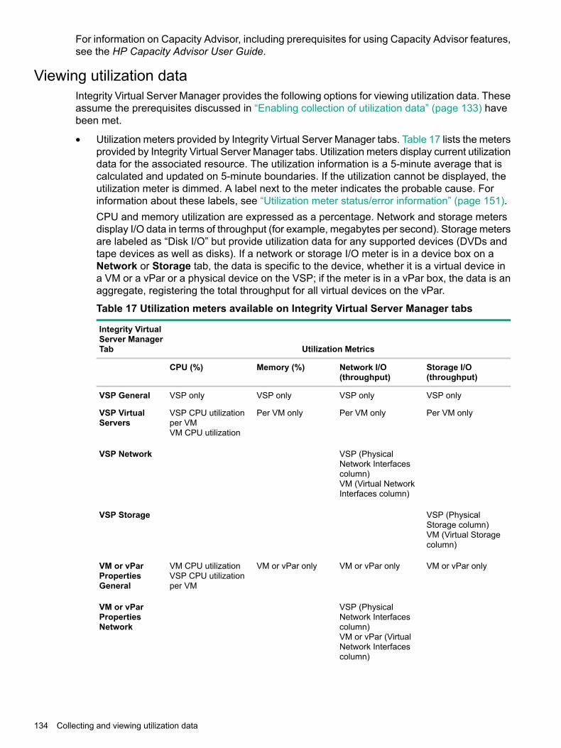
For information on Capacity Advisor, including prerequisites for using Capacity Advisor features,see the HP Capacity Advisor User Guide.
Viewing utilization dataIntegrity Virtual Server Manager provides the following options for viewing utilization data. Theseassume the prerequisites discussed in “Enabling collection of utilization data” (page 133) havebeen met.
• Utilization meters provided by Integrity Virtual Server Manager tabs. Table 17 lists the metersprovided by Integrity Virtual Server Manager tabs. Utilization meters display current utilizationdata for the associated resource. The utilization information is a 5-minute average that iscalculated and updated on 5-minute boundaries. If the utilization cannot be displayed, theutilization meter is dimmed. A label next to the meter indicates the probable cause. Forinformation about these labels, see “Utilization meter status/error information” (page 151).CPU and memory utilization are expressed as a percentage. Network and storage metersdisplay I/O data in terms of throughput (for example, megabytes per second). Storage metersare labeled as “Disk I/O” but provide utilization data for any supported devices (DVDs andtape devices as well as disks). If a network or storage I/O meter is in a device box on aNetwork or Storage tab, the data is specific to the device, whether it is a virtual device ina VM or a vPar or a physical device on the VSP; if the meter is in a vPar box, the data is anaggregate, registering the total throughput for all virtual devices on the vPar.
Table 17 Utilization meters available on Integrity Virtual Server Manager tabs
Utilization Metrics
Integrity VirtualServer ManagerTab
Storage I/O(throughput)
Network I/O(throughput)
Memory (%)CPU (%)
VSP onlyVSP onlyVSP onlyVSP onlyVSP General
Per VM onlyPer VM onlyPer VM onlyVSP CPU utilizationper VMVM CPU utilization
VSP VirtualServers
VSP (PhysicalNetwork Interfacescolumn)VM (Virtual NetworkInterfaces column)
VSP Network
VSP (PhysicalStorage column)VM (Virtual Storagecolumn)
VSP Storage
VM or vPar onlyVM or vPar onlyVM or vPar onlyVM CPU utilizationVSP CPU utilizationper VM
VM or vParPropertiesGeneral
VSP (PhysicalNetwork Interfacescolumn)VM or vPar (VirtualNetwork Interfacescolumn)
VM or vParPropertiesNetwork
134 Collecting and viewing utilization data

Table 17 Utilizationmeters available on Integrity Virtual Server Manager tabs (continued)
Utilization Metrics
Integrity VirtualServer ManagerTab
Storage I/O(throughput)
Network I/O(throughput)
Memory (%)CPU (%)
VSP (PhysicalStorage column)VM or vPar (VirtualStorage column)
VM or vParPropertiesStorage
VSP (PhysicalNetwork Interfacescolumn)VM or vPar (VirtualNetwork Interfacescolumn)
VswitchPropertiesNetwork
NOTE: Data reported by certain Integrity Virtual Server Manager CPU utilization metersmight vary from the data collected by Capacity Advisor as displayed in the Profile Viewerand historical utilization reports. The data from Integrity Virtual Server Manager meters isreliable for most purposes. For capacity planning, refer to the data collected by the CapacityAdvisor Profile Viewer and historical utilization reports. For more information about howCapacity Advisor data might vary from Integrity Virtual Server Manager data, see “DataHandling” in Chapter 3 of the HP Capacity Advisor User Guide.Another source of discrepancy is the difference in the way Capacity Advisor and IntegrityVirtual Server Manager present CPU data. Capacity Advisor Profile Viewer and historicalutilization reports present CPU data in absolute terms (specifying the number of physicalcores used) while Integrity Virtual Server Manager presents CPU data in terms of percentages(specifying the percentage of available CPU resources being used). For example, the IntegrityVirtual Server Manager “VSP CPU Utilization” meter displayed on the VSP Virtual Serversand VM or vPar Properties General tabs displays the percentage of the total VSP physicalCPU capacity used by the VM or vPar in question. Capacity Advisor tabulates similar databut presents it in different terms. For example, on a VSP that has 16 physical cores, if a VMhas 4 CPUs each currently using 50% of a physical core, CapAd would report that the VMis consuming 2 VSP cores. The Integrity Virtual Server Manager “VSP CPU utilization” meterwould report that the VM is consuming 12.5% of the VSP's CPU capacity.
• Using Integrity Virtual Server Manager with HP Matrix Operating Environment:
You can click a utilization meter to view a more detailed historical data report providedby HP Capacity Advisor.
◦
◦ You can use the Integrity Virtual Server Manager View→Capacity Advisor Data...menu item to view a snapshot of recent utilization data collected by HP Capacity Advisor.First, you must enable collection of data by using the Tools→Collect Capacity AdvisorData menu item, as described in “Enabling collection of utilization data” (page 133). (Ifyou use the Integrity Virtual Server Manager View→Capacity Advisor Data... menuitem without having enabled data collection, no data is displayed; however, the screenincludes a link to the Collect Capacity Advisor Data facility so that you can begincollecting data to view.)Figure 94 (page 136) shows the upper half of the screen showing data collected for aVSP, while Figure 95 (page 137) shows the lower half of the screen.
Viewing utilization data 135
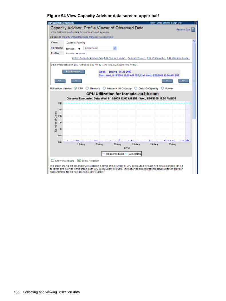
Figure 94 View Capacity Advisor data screen: upper half
136 Collecting and viewing utilization data
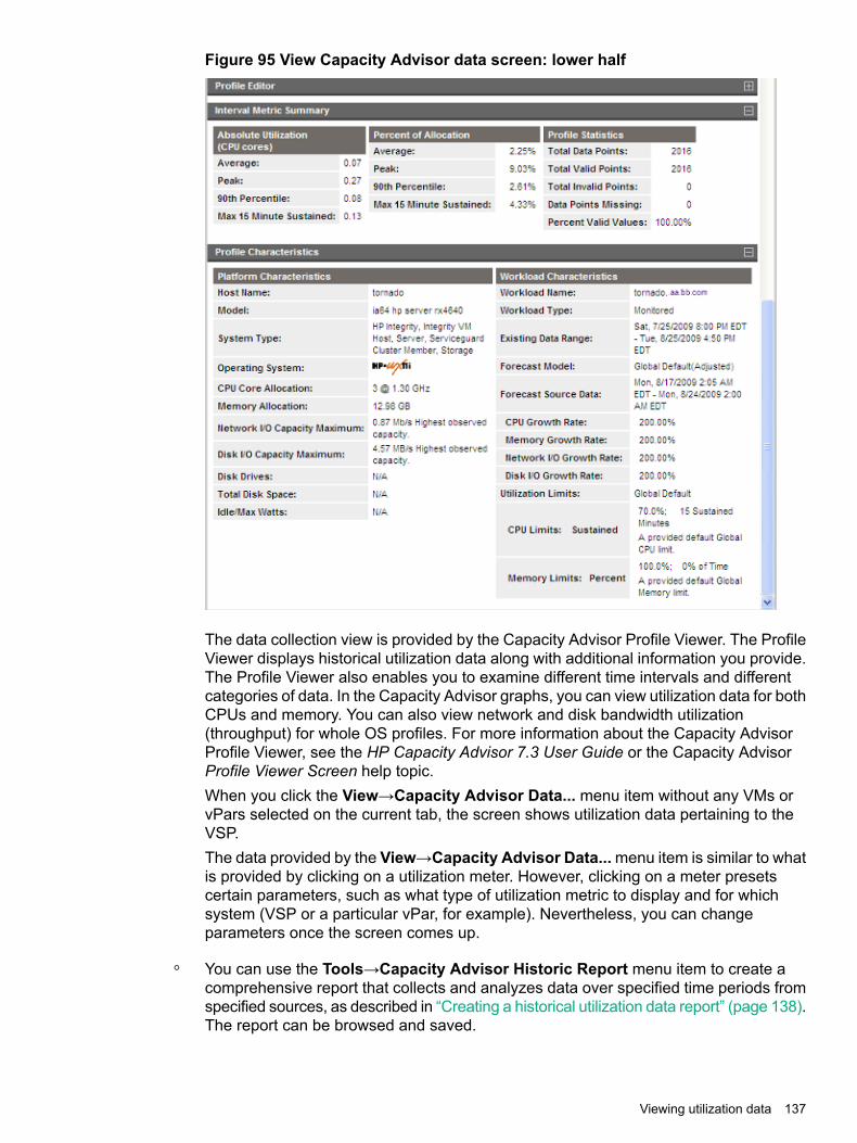
Figure 95 View Capacity Advisor data screen: lower half
The data collection view is provided by the Capacity Advisor Profile Viewer. The ProfileViewer displays historical utilization data along with additional information you provide.The Profile Viewer also enables you to examine different time intervals and differentcategories of data. In the Capacity Advisor graphs, you can view utilization data for bothCPUs and memory. You can also view network and disk bandwidth utilization(throughput) for whole OS profiles. For more information about the Capacity AdvisorProfile Viewer, see the HP Capacity Advisor 7.3 User Guide or the Capacity AdvisorProfile Viewer Screen help topic.When you click the View→Capacity Advisor Data... menu item without any VMs orvPars selected on the current tab, the screen shows utilization data pertaining to theVSP.The data provided by the View→Capacity Advisor Data...menu item is similar to whatis provided by clicking on a utilization meter. However, clicking on a meter presetscertain parameters, such as what type of utilization metric to display and for whichsystem (VSP or a particular vPar, for example). Nevertheless, you can changeparameters once the screen comes up.
◦ You can use the Tools→Capacity Advisor Historic Report menu item to create acomprehensive report that collects and analyzes data over specified time periods fromspecified sources, as described in “Creating a historical utilization data report” (page 138).The report can be browsed and saved.
Viewing utilization data 137

Creating a historical utilization data reportTo use HP Capacity Advisor to create a historical utilization report that includes data for the targetworkloads, systems, complexes, or scenarios you specify, select the Tools→Capacity AdvisorHistoric Report menu item from the Integrity Virtual Server Manager menu bar. This menu itemis available only when you use Integrity Virtual Server Manager with Matrix Operating Environment;it is not available when using Integrity Virtual Server Manager through HP SMH. Before creatinga report, you must have collected data on the systems of interest (see “Enabling collection ofutilization data” (page 133)).HP Capacity Advisor reports provide information about utilization and allocation data that havebeen collected and analyzed. This facility gives you the flexibility of analyzing and showing datacollected over specified time periods. A wizard allows you to set a variety of parameters todetermine the time periods and systems for data collection and analysis. The report can bebrowsed (the screen is presented in a new browser window) and saved. In contrast, theView→Capacity Advisor Data... menu item gives a snapshot of utilization that's more limitedto the current, most recent time period.Capacity Advisor collects data for the following resources or targets: systems, workloads,complexes, and scenarios. For these targets, Capacity Advisor provides utilization informationin the following reports:• System Utilization Report
• Workload Utilization Report
• Complex Utilization Report
• Scenario Utilization Report
138 Collecting and viewing utilization data
8 Viewing logs and version informationViewing VSP, VM, or vPar logs
You can view the events logged by Integrity VM or vPar for the VSP by selecting View→VSPlog... from the Integrity Virtual Server Manager menu bar. This gives a display similar to thatcreated by the hpvmstatus -eM command (used at the Integrity VM CLI), except IntegrityVirtual Server Manager limits the display to the most recent 1000 log lines. The VSP event logrecords all changes to configurations of the VSP and to VMs or vPars on the VSP, includinginformation about commands issued and error messages.You can view the events logged by Integrity VM pertaining to a selected VM or vPar by selectingView→Log for VM or vPar... from the Integrity Virtual Server Manager menu bar (if you are ina VSP or Vswitch Properties view, a VM or a vPar must be selected). This gives the same displaythat the hpvmstatus -eM -P vm-name command would give when used at the Integrity VMCLI (where vm-name is the name of the VM or the vPar). The event log records all changes toconfigurations of the VM or vPar and information about commands issued and error messages.
NOTE: With Integrity Virtual Server Manager running under HP SMH, to view the Integrity VMlogs using either of these Viewmenu items, you must be logged into HP SMH with either Operatoror Administrator privileges. For more information, see the HP SMH documentation, availablefrom the following website:http://www.hpe.com/info/smh
Some reasons that you might want to view either log include the following:• To confirm a change that you made to a running VM or vPar. This is especially useful when
the Integrity Virtual Server Manager does not immediately display the changed data, suchas modification of memory or the number of virtual CPUs for a running VM or vPar. In suchcircumstances, Integrity Virtual Server Manager does not display the new data until the VMor vPar is shut down or restarted.
• To review an error message that resulted from an Integrity VM command run by IntegrityVirtual Server Manager, or to view the actual command line that was run. Integrity VirtualServer Manager displays, or allows you to view this information, at the time of the action.This view allows you to review the information at a later time without having to access a logmanually from the VSP.
• To view commands, logged information, and error messages obtained directly from theIntegrity VM CLI and that might not have been recorded by Integrity Virtual Server Manager.
• To view other information logged on the VSP, such as the status of the VM or the vParsubsystem startup sequence (this information includes whether the VM or vPar startsautomatically when the Integrity VSP starts or remains in the Off state until manually started).
Viewing the VSP logTo view the VSP log:
Viewing VSP, VM, or vPar logs 139

1. Select View→VSP Log in the Virtual Servers tab. The log for VSP is displayed.
Figure 96 View VSP log
2. Click OK to return to the previous screen.
Viewing the VM or vPar logTo view the VM or vPar log:1. SelectView→VMor vPar Log in the Virtual Servers tab. The log for VM or vPar is displayed.
Figure 97 View vPar log
2. Click OK to return to the previous screen.
Viewing Integrity Virtual Server Manager, Integrity VM, and WBEMProvider versions
You can view the version numbers of Integrity Virtual Server Manager, Integrity VM, and WBEMproviders by selecting View→Integrity Virtual Server Manager Version Information from theIntegrity Virtual Server Manager menu bar. The resulting screen reports the current versions of
140 Viewing logs and version information

Integrity VM, of Integrity Virtual Server Manager, and of the providers on both the VSP and eachVM or vPar.Figure 98 shows an example of a screen. If “No Permission” is displayed where a VM's WBEMprovider version or a vPar's WBEM provider version should be, the WBEM credentials (username and password) have not been set for that vPar. For more information on setting WBEMcredentials, see “Setting security credentials” (page 15).
Figure 98 Integrity Virtual Server Manager Version Information screen
Viewing Integrity Virtual Server Manager, Integrity VM, and WBEM Provider versions 141

142
9 Support and other resourcesInformation to collect before contacting HP
Be sure to have the following information available before you contact HP:• Software product name
• Hardware product model number
• Operating system type and version
• Applicable error message
• Third-party hardware or software
• Technical support registration number (if applicable)
How to contact HPUse the following methods to contact HP technical support:• In the United States, see the Customer Service / Contact HP United States website for
contact options:http://www8.hp.com/us/en/hpe/contact/contact.html
• In the United States, call 1-800-HP-INVENT (1-800-474-6836) to contact HP by telephone.This service is available 24 hours a day, 7 days a week. For continuous quality improvement,conversations might be recorded or monitored.
• In other locations, see the Contact HP Worldwide website for contact options:http://www.hpe.com/assistance
Security bulletin and alert policy for non-HP owned software componentsOpen source software (such as OpenSSL) or third-party software (such as Java) are sometimesincluded in HP products. HP discloses that the non-HP owned software components listed in theInsight Management end user license agreement (EULA) are included with Insight Management.The EULA is included with the Insight Management Installer on Insight Management DVD #1.HP addresses security bulletins for the software components listed in the EULA with the samelevel of support afforded HP products. HP is committed to reducing security defects and helpingyou mitigate the risks associated with security defects when they do occur.When a security defect is found, HP has a well defined process that culminates with the publicationof a security bulletin. The security bulletin provides you with a high level description of the problemand explains how to mitigate the security defect.
Subscription serviceHP recommends that you register your product at the Subscriber's Choice for Business website:www.hpe.com/support/e-updatesAfter registering, you will receive email notification of product enhancements, new driver versions,firmware updates, and other product resources.
Registering for software technical support and update serviceInsight Management includes one year of 24 x 7 HP Software Technical Support and UpdateService. This service provides access to HP technical resources for assistance in resolvingsoftware implementation or operations problems.
Information to collect before contacting HP 143
The service also provides access to software updates and reference manuals in electronic formas they are made available from HP.With this service, Insight Management customers benefit from expedited problem resolution aswell as proactive notification and delivery of software updates. For more information about thisservice, see the following website:http://www.hpe.com/services/supportRegistration for this service takes place following online redemption of the license certificate.
How to use your software technical support and updateAs HP releases updates to software, the latest versions of the software and documentation aremade available to you. The Software Updates and Licensing portal gives you access to software,documentation, and license updates for products on your HP software support agreement.You can access this portal from the HP Support Center:www.hpe.com/support/hpescAfter creating your profile and linking your support agreements to your profile, see the SoftwareUpdates and Licensing portal at www.hpe.com/support/e-updates to obtain software,documentation, and license updates.
HP authorized resellersFor the name of the nearest HP authorized reseller, see the following sources:• In the United States, see the HP U.S. service locator website:
www.hpe.com/support/selfrepair
• In other locations, see the Contact HP worldwide website:http://www.hpe.com/assistance
New and changed information in this editionThe VM or vPar properties general tab section is updated with details about base and floatmemory values for vPars.
Related informationDocuments
• HP Matrix Operating Environment Getting Started Guide available at:http://www.hpe.com/info/matrixoe/docs
• HP Integrity Virtual Server Manager User Guide available at:http://www.hpe.com/info/matrixoe/docs
• HP Integrity Virtual Server Manager Release Notes available at:http://www.hpe.com/info/matrixoe/docs
• HP-UX vPars and Integrity VM Release Notes available at:http://www.hpe.com/info/hpux-vpars-docs
144 Support and other resources

• HP-UX vPars and Integrity VM Administrator Guide available at:http://www.hpe.com/info/hpux-vpars-docs
• HP-UX GUID Manager Administrator Guide available at:http://www.hpe.com/info/hpux-vpars-docs
Websites• Matrix Operating Environment documentation http://www.hpe.com/info/matrixoe/docs• Matrix Operating Environment for HP-UX: http://www.hpe.com/info/matrixoe/docs• Matrix Operating Environment: http://www.hp.com/go/matrixoe
Typographic conventionsThis document uses the following typographical conventions:
The title of a book. On the web, this can be a hyperlink tothe book itself.
Book title
A command name or command phrase, for example ls-a.
Command
Information displayed by the computer.Computer output
A key sequence that indicates you must hold down thekeyboard key labeled Ctrl while you press the letter x.
Ctrl+x or Ctrl-x
The name of an environment variable, for example, PATH.ENVIRONMENT VARIABLE
The name of a keyboard key.Return and Enter both referto the same key.
Key
A term or phrase that is defined in the body text of thedocument, not in a glossary.
Term
Indicates commands and text that you type exactly asshown.
User input
The name of a placeholder that you replace with an actualvalue.
Replaceable
In command syntax statements, these characters encloseoptional content.
[ ]
In command syntax statements, these characters encloserequired content.
{ }
The character that separates items in a linear list ofchoices.
|
Indicates that the preceding element can be repeated oneor more times.
...
An alert that calls attention to important information that,if not understood or followed, results in personal injury.
WARNING
An alert that calls attention to important information that,if not understood or followed, results in data loss, datacorruption, or damage to hardware or software.
CAUTION
An alert that calls attention to essential information.IMPORTANT
Typographic conventions 145

An alert that contains additional or supplementaryinformation.
NOTE
An alert that provides helpful information.TIP
146 Support and other resources

10 Documentation feedbackHP is committed to providing documentation that meets your needs. To help us improve thedocumentation, send any errors, suggestions, or comments to Documentation [email protected]. Include the document title and part number, version number, or theURL when submitting your feedback.
147

148

A Error messages, status indicators, and troubleshootingThis appendix discusses error messages and troubleshooting related to Integrity Virtual ServerManager problems, and describes the status indicators that appear on some Integrity VirtualServer Manager screens and the error and status labels that might appear with utilization meters(bar graphs) displayed on certain Integrity Virtual Server Manager screens.
Error messagesError messages visible in Integrity Virtual Server Manager are returned primarily from the IntegrityVM commands themselves. This section describes how to review such error messages as loggedby Integrity VM and includes information about error messages that might be seen when attemptingto access Integrity Virtual Server Manager. Other errors or problems are discussed in“Troubleshooting VM or vPar problems” (page 152).
Reviewing error messagesTo review an error message that resulted from an Integrity VM command run by Integrity VirtualServer Manager in the past (and so is not currently viewable), you can select View→VSP log...or View→VM or vPar log.... The former menu item displays events logged by Integrity VM thatpertain to the VSP and all its guests. The latter menu item displays events logged by IntegrityVM that pertain to a specific VM or vPar. For more information, see “Viewing VSP, VM, or vParlogs” (page 139).For more information about error messages related to Integrity VM, see the HP-UX vPars andIntegrity VM Administrator Guide manual.
Errors accessing Integrity Virtual Server ManagerUnder certain circumstances, errors can occur when attempting to enter Integrity Virtual ServerManager from HP Matrix OE visualization (Matrix Operating Environment for HP-UX) or from theHP System Management Homepage. In those cases, a page titled “Access failure” is displayedwith the name of the VSP system and the reason for the failure to enter Integrity Virtual ServerManager. The following list describes the access failure messages that you might receive:
• Incorrect permissions. An error occurred communicating with WBEM:CIM_ERR_ACCESS_DENIED CIM_ERR_ACCESS_DENIED: PGS05203.The following is an example of the error message displayed for a user, hpsmh:The user 'hpsmh' is not authorized to run 'EnumerateInstances' inthe namespace 'root/cimv2/hpvm'.CIM_ERR_ACCESS_DENIED (part of the error message mentioned earlier) indicates that aCIM user is not authorized to access the namespace.This error occurs when a user with specific credentials uses a WBEM connection to accessthe VM WBEM services listening at ports 5988 and 5989 without sufficient permissions. Fora WBEM user to access the WBEM services, the user must be provided with sufficientpermissions.This issue does not occur if the CIM configuration parameterenableNamespaceAuthorization is set to FALSE. If the value is set to FALSE,irrespective of whether the users are SIM or SMH users, they can access WBEM services.To resolve the issue, first examine the value of the configuration parameter,enableNamespaceAuthorization.To examine the configuration parameter settings, run the following command:cimconfig -lp
This command lists all the configuration parameters. Verify whether theenableNamespaceAuthorization parameter is set to TRUE. If it is set to TRUE, followthese steps:
Error messages 149

1. To access WBEM Providers from HP Systems Insight Manager, run the followingcommand:# cimauth -a -u <SIMUSER> -n root/cimv2/hpvm -R -W
# cimconfig -s enableNamespaceAuthorization=true -p
where, SIMUSER is the username created for SIM access.2. To access WBEM Providers from HP SMH, run the following command:
# cimauth -a -u <SMHUSER> -n root/cimv2/hpvm -R -W
# cimconfig -s enableNamespaceAuthorization=true -p
where, SMHUSER is the username created for SMH access.
• The user is not authorized to monitor the VSP in Systems InsightManager/Matrix Operating Environment. Authority to monitor the VSPis required when using Integrity Virtual Server Manager for accessingthe VSP or for accessing any hosted VM within the Matrix OperatingEnvironment environment.
To use Integrity Virtual Server Manager, an Systems Insight Manager/Matrix OperatingEnvironment user must have at least Monitor Tools authorization for the VSP system. If auser has authority to manage an individual VM or vPar but is not authorized within SystemsInsight Manager/Matrix Operating Environment to monitor the VSP system that contains it,the error message appears when the user selects the Integrity Virtual Server Manager iconin the VM's or vPar's system box displayed by the HP Matrix OE visualization Visualizationtab. To return to HP Matrix OE visualization, select All VSE Resources in the left-handnavigation pane of Systems Insight Manager/Matrix Operating Environment (System andEvent Collections→Systems→Shared→Systems by Type→All VSE Resources).
• The VSP is not known to Systems Insight Manager/Matrix OperatingEnvironment. The VSP must be known to use Integrity Virtual ServerManager for the VSP or for any VSPed by it.
It is possible that a VM or a vPar might be discovered by Systems Insight Manager whilethe containing VSP has not yet been discovered. To use Integrity Virtual Server Manager,both the VM or vPar and the containing VSP must be discovered by Systems Insight Manager.This error message appears when you select a VM or vPar link in the VM or vPar systembox displayed in HP Matrix OE visualization before Systems Insight Manager has discoveredthe VM's or vPar's VSP. To return to HP Matrix OE visualization, select the All VSEResources link in the left-hand navigation bar of Systems Insight Manager (System andEvent Collections→Systems→Shared→Systems by Type→All VSE Resources).
• The user is not authorized to use Integrity Virtual Server Manageron this VSP.
With HP SMH, Integrity Virtual Server Manager is configured by default to permit read-onlyaccess to HP SMH users with User-level privileges, and read-write access to HP SMH userswith Operator-level and Administrator-level privileges. However, it is possible to reconfigurethese permissions to deny all Integrity Virtual Server Manager access to User-level andOperator-level users. In this case, these users can log into HP SMH, but they are deniedaccess to Integrity Virtual Server Manager. To return to the SMH Homepage, select Homein the top navigation link.With Matrix Operating Environment for HP-UX, users need VSE All Tools authorization toview all Integrity Virtual Server Manager screens and perform all Integrity Virtual ServerManager menu actions.
If other messages are displayed on an Access failure page, contact your HP Technical SupportRepresentative for further assistance.
150 Error messages, status indicators, and troubleshooting
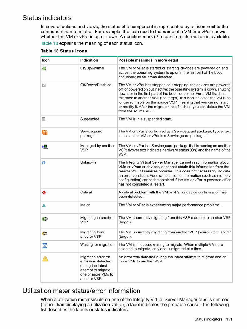
Status indicatorsIn several actions and views, the status of a component is represented by an icon next to thecomponent name or label. For example, the icon next to the name of a VM or a vPar showswhether the VM or vPar is up or down. A question mark (?) means no information is available.Table 18 explains the meaning of each status icon.
Table 18 Status icons
Possible meanings in more detailIndicationIcon
The VM or vPar is started or starting; devices are powered on andactive; the operating system is up or in the last part of the bootsequence; no fault was detected.
On/Up/Normal
The VM or vPar has stopped or is stopping; the devices are poweredoff, or powered on but inactive; the operating system is down, shuttingdown, or in the first part of the boot sequence. For a VM that hasmigrated to another VSP (the target), this icon indicates the VM is nolonger runnable on the source VSP, meaning that you cannot startor modify it. After the migration has finished, you can delete the VMfrom the source VSP.
Off/Down/Disabled
The VM is in a suspended state.Suspended
The VM or vPar is configured as a Serviceguard package; flyover textindicates the VM or vPar is a Serviceguard package.
Serviceguardpackage
The VM or vPar is a Serviceguard package that is running on anotherVSP; flyover text indicates hardware status (On) and the name of theVSP.
Managed by anotherVSP
The Integrity Virtual Server Manager cannot read information aboutVMs or vPars or devices, or cannot obtain this information from theremote WBEM services provider. This does not necessarily indicatean error condition. For example, some information (such as memoryconfiguration) cannot be obtained if the VM or vPar is powered off orhas not completed a restart.
Unknown
A critical problem with the VM or vPar or device configuration hasbeen detected.
Critical
The VM or vPar is experiencing major performance problems.Major
The VM is currently migrating from this VSP (source) to another VSP(target).
Migrating to anotherVSP
The VM is currently migrating from another VSP (source) to this VSP(target).
Migrating fromanother VSP
The VM is in queue, waiting to migrate. When multiple VMs areselected to migrate, only one is migrated at a time.
Waiting for migration
An error was detected during the latest attempt to migrate one ormore VMs to another VSP.
Migration error Anerror was detectedduring the latestattempt to migrateone or more VMs toanother VSP.
Utilization meter status/error informationWhen a utilization meter visible on one of the Integrity Virtual Server Manager tabs is dimmed(rather than displaying a utilization value), a label indicates the probable cause. The followinglist describes the labels or status indicators:
Status indicators 151

• No Comm. indicates that Integrity Virtual Server Manager is unable to communicate withthe WBEM provider running on a VM or vPar. Hover the cursor over the meter to display anexception error message identifying the problem.A common reason for the No Comm. label to be displayed is a problem with trustedcertificates. For example, if trusted certificates are required (theRequire trusted certificatescheck box was selected on the Set WBEM Credentials for VM or vPar page) but thekeystore on the VSP does not trust the certificate from the VM or vPar, then the certificateis not in the keystore, has expired, did not match the VM or vPar name, or is otherwiseinvalid. For information about trusted certificates, see “Trusted certificates” (page 18).If the WBEM provider is unresponsive, you might need to restart it.
• No Data indicates one of the following:
Data is being collected, but it can take up to 10 minutes to display utilization data.◦◦ The VM or vPar is not started, not booted, or cannot be contacted by the system on
which Integrity Virtual Server Manager is running.
◦ The VSP has no WBEM credentials for collecting the data from the VM or vPar. Normally,this is only seen for invalid or missing WBEM credentials for a Windows VM guest. Seethe discussion of the No Perm label.For more information about WBEM credentials,see “Setting security credentials” (page 15).
For more information about problems displaying data (data is out of date, incomplete, ormissing), see “Troubleshooting VM or vPar problems” (page 152).
• No Perm. indicates that the VSP lacks or has invalid WBEM credentials for collecting thedata from the VM or vPar.
• Timed Out indicates that Integrity Virtual Server Manager attempted to retrieve utilizationdata but received no response from the WBEM provider on the VM or vPar because of oneof the following situations:
◦ The WBEM provider for the data is not running, is not installed, or is disabled on theVM or vPar.
◦ Network problems are preventing a timely response.
For more information about collecting and viewing utilization data, see Chapter 7 (page 133).
Troubleshooting VM or vPar problemsThis section discusses problems that might occur when using Integrity Virtual Server Managerto create, start, or modify a VM or a vPar or to display VM or vPar data. Also included are waysfor resolving these problems.
• Failure creating a VMWhen using the Create Virtual Machines wizard, a number of warning or error conditionscan prevent the VM or vPar from being created. However, if theCreate VM even if resourcesare insufficient, missing or unavailable check box is selected on the Create Virtual
152 Error messages, status indicators, and troubleshooting

Machines wizard Summary page, you can still have Integrity Virtual Server Manager createthe VM. You will have to correct the conditions prior to starting the VM.
• Failure starting a VM or a vParThe most likely cause for a VM or a vPar failing to start is missing, insufficient, or unavailableresources. Make sure the required resources are made available. For example:
◦ Not enough memory on the VSP is available for the VM or vParMake sure that enough memory is available on the VSP to provide the memory youallocated for the new VM or vPar (in addition to providing for the existing VMs or vPars).
◦ You specified a device that is already in use by another VM or vParYou might have specified a network or storage device that is already in use by anotherVM or vPar. You need to return to the appropriate Create Wizard page to select a devicethat is not in use. To determine what devices are already in use, examine the VSPNetwork or VSP Storage tab.
◦ A file specified as a backing device does not existYou might have incorrectly specified the name or path of a file to be used as a backingstorage device, or you specified a file that does not exist.
◦ The VM is currently migrating online or has migrated to another VSP (and is in a NotRunnable state).
• Failure to modify the VM CPU entitlementIf you attempt to modify (by selectingModify→CPUEntitlement for VM) the CPU entitlementof a VM that is being managed by gWLM, the following error message is displayed, wherevirtual-machine-name is the name of the VM:The processor entitlement for VM virtual-machine-name cannot bemodified because it is being managed by gWLM. To adjust the processorentitlement for this VM, use gWLM to change the policy associatedwith this VM.
To create or modify the gWLM policy for this VM, use the Policymenu (available when usingIntegrity Virtual Server Manager with the Matrix Operating Environment for HP-UX).
• Information is out of date, incomplete, or missingIn general, Integrity Virtual Server Manager tabbed view screens are refreshed automaticallyevery five minutes. An indicator on these visualization pages notifies you when the data waslast refreshed. Integrity Virtual Server Manager screens that display configuration data areupdated instantaneously when you use Integrity Virtual Server Manager to change the relatedconfiguration parameters.
NOTE: When changes to VM or vPar I/O configuration are made using tools other thanIntegrity Virtual Server Manager (such as adding or removing I/O devices by using the VSPcommand line), the updated configuration data is not shown until the screen is refreshed.You can manually refresh a tabbed view screen and certain dialog screens (such as thosefor adding storage or network devices) by clicking on the Refresh Data link.
If information about certain VMs or vPars is missing from a Integrity Virtual Server Managerscreen (for example, specifics about a port interface), the screen might need refreshing, theVMs or vPars might not yet be started or, if they are started, the VM Provider or certainWBEM components might not be running on those VMs or vPars or on the VSP. WBEMcomponents are required on any VM or vPar for which you want data. If the VM Provider isnot running on the VSP, no data will be available on any Integrity Virtual Server Managertabs; all tabs will display a “No data available” message. To verify that the VM Provider isrunning, enter the following command on the VM or vPar or VSP:cimprovider -ls
Troubleshooting VM or vPar problems 153

The response “HPVMProviderModule OK” indicates the VM Provider is running. Any otherresponse indicates it is not running. For system and software requirements regarding theVM Provider, see “System and software requirements” (page 13). For installation instructionsand information about providers that must be installed and running on VMs or vPars, seethe HP-UX vPars and Integrity VM Administrator Guide manual.
• Device special file displayed as unknown device ( )If you use Integrity Virtual Server Manager to manage a VSP running Integrity VM Version3.5 or earlier, Integrity Virtual Server Manager does not fully support virtual device specialfiles located in /hpap (introduced in HP StorageWorks Secure Path software Version 3.0FSP2) as backing devices for virtual storage. If a virtual storage device using an /hpap devicespecial file already exists on a VM or vPar managed by Integrity Virtual Server Manager,Integrity Virtual Server Manager displays it on the VSP Storage and VMProperties Storagetabs as an unknown device (using the question mark icon, ). Integrity Virtual Server Managerdisplays the correct device special file name (for example, /hpap/rdsk/hpap1) but thebox representing this device is not connected to the boxes that represent the physical storagedevices associated with that virtual device special file. In general, Integrity Virtual ServerManager correctly displays only those device special files located in /dev.
• Created VM or vPar does not appear immediately in HP Matrix OE visualizationAfter creating a VM or vPar using Integrity Virtual Server Manager, if you return immediatelyto HP Matrix OE visualization, the machine might not yet appear in HP Matrix OE visualization.This means Systems Insight Manager has not yet completed identifying the new VM or vPar.However, it appears when the identification process completes (usually within a minute ortwo).
154 Error messages, status indicators, and troubleshooting

GlossaryThe following terms are commonly used to discuss Integrity Virtual Server Managerand its integrated components:
AcceleratedVirtualInput/Output
See AVIO.
agent A program that regularly gathers information or performs some other service without the user'simmediate presence. Matrix Operating Environment for HP-UX relies on agents on managedsystems to provide in-depth hardware and software information.
agile addressing Supported on Integrity VM running HP-UX 11i v3, a storage device addressing model thataddresses a logical unit (referred to as LUN, this is the logical device that refers to the physicalstorage device) by using the same device special file (DSF) regardless of the location of theLUN. The addressing model uses a worldwide device identifier (WWID) to uniquely identifyLUNs. The WWID is a device attribute that is independent of the device s location in a SANor in an adapter/controller access path. With a multipath device, the WWID allows one persistentDSF and one LUN hardware path to represent the device, regardless of the number of legacyhardware paths. Therefore, an agile device address remains the same (is persistent) whenchanges are made to the access path. Likewise, if additional paths are offered to a given LUN(by adding a new SCSI controller or new SCSI target paths), the DSF is unaffected: no newDSFs need be provided. This model enables Integrity Virtual Server Manager to display oneDSF for each multipath device instead of displaying a separate DSF for each path to the device(as done when using the legacy addressing scheme).See also legacy addressing.
APA Automatic Port Aggregation. A combination of LAN ports that can be accessed through a singleinterface name. An APA creates link aggregates (often called trunks) that provide a logicalgrouping of two or more physical ports into a single “fat pipe.” This port arrangement providesmore data bandwidth and higher reliability than would otherwise be available.
AVIO Accelerated Virtual Input/Output. An I/O protocol that improves virtual I/O performance fornetwork and storage devices used within the Integrity VM environment. The protocol alsoenables support for a greater number of virtual I/O devices per guest. For each vPar containingan AVIO device, the VSP OS and the guest OS must support AVIO.
backing device Backing store. The physical device (such as a network adapter, a disk, or a file) on the VSPthat is allocated to guests.
cluster Two or more systems configured together to host workloads. Users are unaware that more thanone system is hosting the workload.
core The actual data-processing engine within a processor. A single processor might have multiplecores, and a core might support multiple execution threads. A virtual processor core in a VMis also called a vCPU.See also processor.
CPU Virtual CPU. A single-core virtual processor in a virtual machine or virtual partition.See also core, processor.
dedicatedvswitch
A vswitch that is dedicated to use by a certain virtual machine or virtual partition. This type ofvswitch cannot be shared by multiple vPars running at the same time.
EFI Extensible Firmware Interface. The system firmware user interface that allows boot-relatedconfiguration changes and operations on Itanium-based systems. For example, EFI providesways to specify boot options and list boot devices.
entitlement The amount of a system resource (for example, processor resources) that is guaranteed to avirtual machine. The actual allocation of resources to the VM can be greater or less than itsentitlement, depending on the VM's demand for processor resources and the overall systemprocessor load.
entitlement cap The maximum amount of computing power allotted to a virtual machine for each CPU.guest The vPar running the guest OS and guest applications.
155
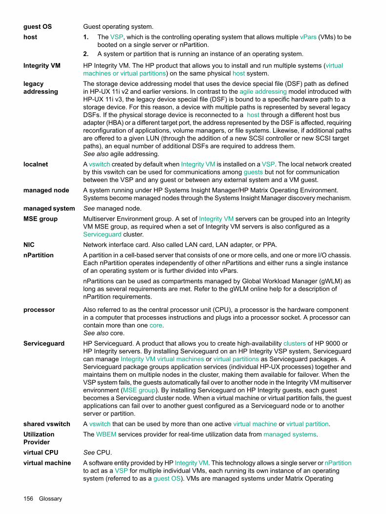
guest OS Guest operating system.host The VSP, which is the controlling operating system that allows multiple vPars (VMs) to be
booted on a single server or nPartition.1.
2. A system or partition that is running an instance of an operating system.
Integrity VM HP Integrity VM. The HP product that allows you to install and run multiple systems (virtualmachines or virtual partitions) on the same physical host system.
legacyaddressing
The storage device addressing model that uses the device special file (DSF) path as definedin HP-UX 11i v2 and earlier versions. In contrast to the agile addressing model introduced withHP-UX 11i v3, the legacy device special file (DSF) is bound to a specific hardware path to astorage device. For this reason, a device with multiple paths is represented by several legacyDSFs. If the physical storage device is reconnected to a host through a different host busadapter (HBA) or a different target port, the address represented by the DSF is affected, requiringreconfiguration of applications, volume managers, or file systems. Likewise, if additional pathsare offered to a given LUN (through the addition of a new SCSI controller or new SCSI targetpaths), an equal number of additional DSFs are required to address them.See also agile addressing.
localnet A vswitch created by default when Integrity VM is installed on a VSP. The local network createdby this vswitch can be used for communications among guests but not for communicationbetween the VSP and any guest or between any external system and a VM guest.
managed node A system running under HP Systems Insight Manager/HP Matrix Operating Environment.Systems become managed nodes through the Systems Insight Manager discovery mechanism.
managed system See managed node.MSE group Multiserver Environment group. A set of Integrity VM servers can be grouped into an Integrity
VM MSE group, as required when a set of Integrity VM servers is also configured as aServiceguard cluster.
NIC Network interface card. Also called LAN card, LAN adapter, or PPA.nPartition A partition in a cell-based server that consists of one or more cells, and one or more I/O chassis.
Each nPartition operates independently of other nPartitions and either runs a single instanceof an operating system or is further divided into vPars.nPartitions can be used as compartments managed by Global Workload Manager (gWLM) aslong as several requirements are met. Refer to the gWLM online help for a description ofnPartition requirements.
processor Also referred to as the central processor unit (CPU), a processor is the hardware componentin a computer that processes instructions and plugs into a processor socket. A processor cancontain more than one core.See also core.
Serviceguard HP Serviceguard. A product that allows you to create high-availability clusters of HP 9000 orHP Integrity servers. By installing Serviceguard on an HP Integrity VSP system, Serviceguardcan manage Integrity VM virtual machines or virtual partitions as Serviceguard packages. AServiceguard package groups application services (individual HP-UX processes) together andmaintains them on multiple nodes in the cluster, making them available for failover. When theVSP system fails, the guests automatically fail over to another node in the Integrity VM multiserverenvironment (MSE group). By installing Serviceguard on HP Integrity guests, each guestbecomes a Serviceguard cluster node. When a virtual machine or virtual partition fails, the guestapplications can fail over to another guest configured as a Serviceguard node or to anotherserver or partition.
shared vswitch A vswitch that can be used by more than one active virtual machine or virtual partition.UtilizationProvider
The WBEM services provider for real-time utilization data from managed systems.
virtual CPU See CPU.virtual machine A software entity provided by HP Integrity VM. This technology allows a single server or nPartition
to act as a VSP for multiple individual VMs, each running its own instance of an operatingsystem (referred to as a guest OS). VMs are managed systems under Matrix Operating
156 Glossary
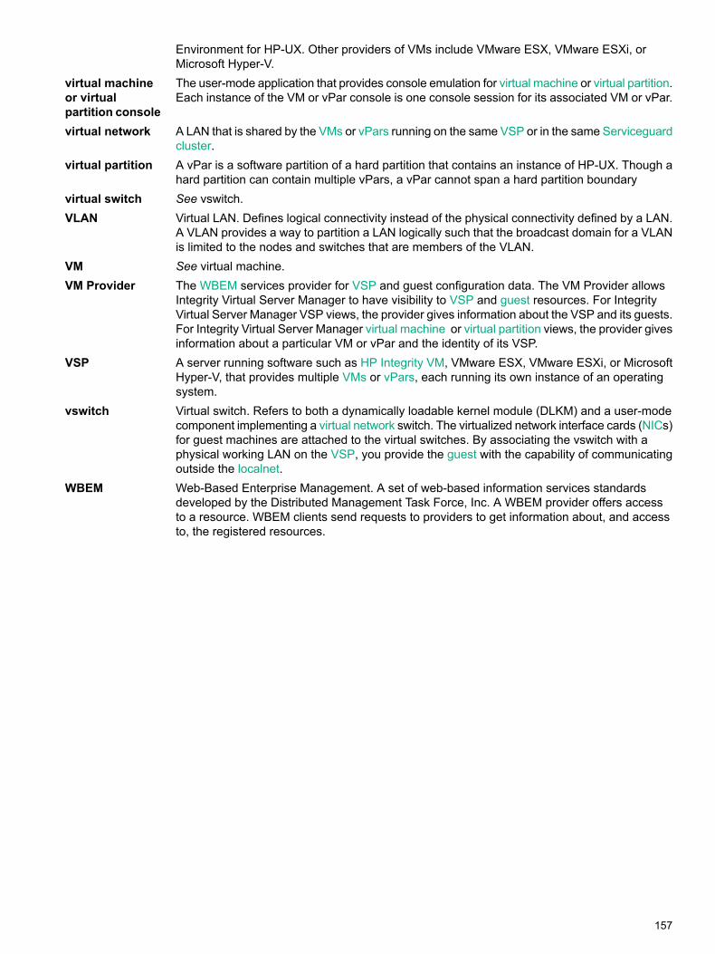
Environment for HP-UX. Other providers of VMs include VMware ESX, VMware ESXi, orMicrosoft Hyper-V.
virtual machineor virtualpartition console
The user-mode application that provides console emulation for virtual machine or virtual partition.Each instance of the VM or vPar console is one console session for its associated VM or vPar.
virtual network A LAN that is shared by the VMs or vPars running on the same VSP or in the same Serviceguardcluster.
virtual partition A vPar is a software partition of a hard partition that contains an instance of HP-UX. Though ahard partition can contain multiple vPars, a vPar cannot span a hard partition boundary
virtual switch See vswitch.VLAN Virtual LAN. Defines logical connectivity instead of the physical connectivity defined by a LAN.
A VLAN provides a way to partition a LAN logically such that the broadcast domain for a VLANis limited to the nodes and switches that are members of the VLAN.
VM See virtual machine.VM Provider The WBEM services provider for VSP and guest configuration data. The VM Provider allows
Integrity Virtual Server Manager to have visibility to VSP and guest resources. For IntegrityVirtual Server Manager VSP views, the provider gives information about the VSP and its guests.For Integrity Virtual Server Manager virtual machine or virtual partition views, the provider givesinformation about a particular VM or vPar and the identity of its VSP.
VSP A server running software such as HP Integrity VM, VMware ESX, VMware ESXi, or MicrosoftHyper-V, that provides multiple VMs or vPars, each running its own instance of an operatingsystem.
vswitch Virtual switch. Refers to both a dynamically loadable kernel module (DLKM) and a user-modecomponent implementing a virtual network switch. The virtualized network interface cards (NICs)for guest machines are attached to the virtual switches. By associating the vswitch with aphysical working LAN on the VSP, you provide the guest with the capability of communicatingoutside the localnet.
WBEM Web-Based Enterprise Management. A set of web-based information services standardsdeveloped by the Distributed Management Task Force, Inc. A WBEM provider offers accessto a resource. WBEM clients send requests to providers to get information about, and accessto, the registered resources.
157

158
Index
AAccelerated Virtual Input/Output see AVIOagile device addressing
Add Storage screen, 94APA, 115Automatic Port Aggregation see APAAVIO
performance tuning, 91support indication, Create Vswitch screen, 114support information, 96, 125
AVIO backing devicesupport indication, VSP view, 36support indication, Vswitch Properties view, 79
AVIO networkadding, 92support indication, VM Properties view, 75
AVIO storageadding, 93
Bbacking device
AVIO support indication, 36, 79, 114selecting for network, 92selecting for storage, 94selecting for vswitch, 115
CCapacity Advisor
and Integrity Virtual Server Manager, 11collecting data for, 133displaying collected data, 134, 135historical report, 138requirements, 13
core, 7see also CPU
CPU, 7modifying allotment, 86
CPU core resourcesVM Properties view, 69VSP view, 31
CPU countdisplaying, 69
CPU entitlementdisplaying, 69
Create Virtual Machine wizard, 91credentials, WBEM, 15
Eentitlement see CPU entitlementerror messages, 149event logs
viewing, 139virtual partition, displaying using View menu, 89VSP, displaying using View menu, 89
external managersVirtual Server Manager Properties view, 74
VSP view, 31
Ffocus link
VSP Storage tab, 45Vswitch Properties Network tab, 80
GGlobal Workload Manager see gWLMgraceful stop timeout
displaying, 69guest OS
specifying for new VM, 91starting automatically, 96, 125
gWLMand Integrity Virtual Server Manager, 11
gWLM policyVirtual Server Manager Properties view (Virtual Server
Manager), 74VM Properties view, 70VSP view, 31VSP view (Integrity Virtual Server Manager), 32
Hhelp
accessing, 24historical utilization data report
creating, 138HP Matrix OE visualization
accessing from Integrity Virtual Server Manager, 26accessing from Matrix Operating Environment, 21accessing Integrity Virtual Server Manager from, 23and Integrity Virtual Server Manager, 11requirements, 13
HP Matrix Operating Environmentdocumentation, 144
HP Matrix Operating Environment for HP-UXaccessing Integrity Virtual Server Manager from, 21and Integrity Virtual Server Manager, 9
HP SIMaccessing Integrity Virtual Server Manager from, 21documentation, 144installing Integrity Virtual Server Manager on, 14licensing, 15
HP SMHaccessing from Integrity Virtual Server Manager, 26accessing Integrity Virtual Server Manager from, 23and Integrity Virtual Server Manager, 9documentation, 11installing Integrity Virtual Server Manager on, 14licensing, 15
HP Systems Insight Managerand Integrity Virtual Server Manager, 9
II/O device
adding (network) to new virtual machine, 92
159

adding (storage) to new virtual machine, 93adding to existing VM, 98, 99deleting, 88, 116
Insight Capacity Advisor software see Capacity AdvisorInsight Global Workload Manager see gWLMIntegrity Virtual Server Manager
accessing, 21Create menu, 85Delete menu, 87focus link
VSP Storage tab, 45Vswitch Properties Network tab, 80
help, 24installing, 13Maximize link, 29menus, 83Modify menu, 86navigating, 24Refresh Data link, 29Restore Size link, 29setting up, 13Show All link
VSP Storage tab, 45Vswitch Properties Network tab, 80
system requirements, 13table sorting, 25tasks, 11Tools menu, 83View menu, 88View normal link, 29View Printer-friendly link, 29viewing version of, 15, 89, 140views and tabs, 29
Integrity VMevent logs, 139overview, 7viewing version of, 89, 140
Llegacy device addressing
Add Storage screen, 94licensing, 15logs see event logs
MMaximize link, 29memory
displaying, 70modifying, 97specifying, 92utilization, 134VM Properties view, 69VSP view, 31
Migrate Guest wizardoverview, 106step 1 screen, 109step 2 screen, 110
migrationoverview, 106
phase timeouts, 109planning and recommendations, 107previewing and invoking commands, 110specifying VSP, 109starting, 109status and error notification, 108status and errors, 108support and status, 34, 70, 71VSP support status, 32
Multiserver Environment group see MSE group
Nnetwork device
adding to existing VM, 99adding to new VM, 92deleting, 88, 116VM Properties view, 74VSP view, 36Vswitch Properties view, 79
Pprinter-friendly view, 29providers
enabling use of, 15utilization meter status and error information, 151viewing version of, 89, 140
RRefresh Data link, 29Reset menu
overview, 129Restore Size link, 29
Ssecurity certificates, 18Serviceguard, 71, 151
Virtual Server Manager Properties view (Virtual ServerManager), 74
VSP View, 34VSP view (Integrity Virtual Server Manager), 32
Serviceguard packagesand modifying VMs, 99
Serviceguard supportVM Properties view , 70VSP view , 31
Shared Resource Domain see SRDShow All link
VSP Storage tab, 45Vswitch Properties Network tab, 80
SRDadding new VMs to, 97, 125
SSL certificates, 17, 18startup attribute see virtual partition startup attributeStop menu
overview, 128storage device
adding to existing VM, 98adding to new VM, 93deleting, 88, 116
160 Index
VM Properties view, 76VSP view, 44, 51
support and feedback, 143system requirements, 13
TTools menu
resetting vPars, 129stopping vPars, 128
trusted certificatesenabling, 17, 18
typographic conventions, 145
Uutilization data
collecting and viewing, 133creating a report, 138viewing, 134
utilization meterand WBEM credentials, 17error, 18errors and status, 151general discussion, 133table of available meters, 134viewing, 134virtual partition, 33Virtual Server Manager Properties view, 74VM or vPar, 70VM or vPar network I/O, 75VM or vPar storage I/O, 77VSP, 31VSP Network tab, 37VSP storage I/O, 45
VvCPU
modifying processor entitlement for, 97, 98specifying processor entitlement for, 91
vCPU countspecifying, 91, 98
vCPU entitlementspecifying, 91, 97
View normal link, 29View Printer-friendly link, 29virtual CPU see CPUvirtual LAN see VLANvirtual machine
creating, 91deleting, 105migrating, 106modifying, 97planning, 91restarting, 104starting, 102stopping, 103
virtual machine identityspecifying, 91
virtual machine startup attributespecifying, 91
virtual partition, 7see also VM or vPar Propertiescreating, 85deleting, 88Integrity VM event logs, 89migration status, 34properties of, 89restarting, 84starting, 84stopping, 84utilization meters, 33viewing properties of, 89
virtual partition entitlement see CPU entitlementvirtual partition OS see guest OSvirtual server
migration status, 33VSP view, 33
Virtual Server Environment see VSEvirtual switch see vswitchVLAN
displaying port assignments, 79ID, 79modifying ID, 98modifying settings of, 86removing port assignments, 105specifying ID, 96
VM console, 96, 125VM or vPar
migration status, 70, 71properties of, 67utilization meters, 70viewing properties of, 67
VM or vPar authorization informationdisplaying, 69
VM or vPar graceful stop timeoutspecifying (Integrity Virtual Server Manager), 72
VM or vPar identitydisplaying, 69
VM or vPar PropertiesGeneral tab, 68
VM or vPar startup attributedisplaying, 69
VM PropertiesNetwork tab, 74Storage tab, 76
VM startup attributemodifying, 98
VP Propertiesview, 67
VSPGeneral tab, 30Integrity VM event logs, 89Network tab, 36Storage tab, 44, 51storage utilization meters, 45utilization meters, 31view, 29Virtual Servers tab, 33Virtual Switches tab, 35
161
vswitchcreating, 85, 113deleting, 88, 116properties of, 77, 89starting, 84, 116stopping, 85, 116viewing properties of, 77, 89VSP view, 35
Vswitch PropertiesGeneral tab, 78Network tab, 79view, 77
WWBEM
setting credentials in HP SIM, 16setting credentials in HP SMH, 16
WBEM credentialsmodifying, 98
WBEM providersenabling use of, 15utilization meter status and error information, 151viewing version of, 89, 140
wizardmigrating virtual machines, 106
162 Index