hp-ux 10.20 operating and software maintenance procedures for continuum ... 10.20... · hp-ux 10.20...
TRANSCRIPT
HP-UX 10.20 Operating and SoftwareMaintenance Procedures for Continuum 400
Series(2/20/98)
Revision History
11/5/97 - Revision 0 (GA Version) 2/20/98 - Updated Section 2.5.1
1 of 1 3/9/98 9:14 AM
HP-UX Continuum 400 Series Technical Service Guide file:///F|/CSDoc/hpux1020/title.htm

NoticeThe information contained in this document is subject to change without notice.
STRATUS COMPUTER, INC. MAKES NO WARRANTY OF ANY KIND WITH REGARD TO THISMATERIAL, INCLUDING, BUT NOT LIMITED TO, THE IMPLIED WARRANTIES OFMERCHANTABILITY AND FITNESS FOR A PARTICULAR PURPOSE. Stratus Computer, Inc.,shall not be liable for errors contained herein or incidental or consequential damages in connection withthe furnishing, performance, or use of this material.
Software described in Stratus documents (a) is the property of Stratus Computer, Inc., or the third party,(b) is furnished only under license, and (c) may be copied or used only as expressly permitted under theterms of the license.
This document is protected by copyright. All rights are reserved. No part of this document may becopied, reproduced, or translated, either mechanically or electronically, without the prior written consentof Stratus Computer, Inc.
Stratus, Continuum, Continuous Processing, StrataNET, FTX, and the Stratus logo are registeredtrademarks of Stratus Computer, Inc.
XA, XA/R, StrataLINK, RSN, SINAP, Isis, Isis Distributed, RADIO, and the SQL/2000 logo aretrademarks of Stratus Computer, Inc.
Hewlett-Packard and HP are registered trademarks of Hewlett-Packard.IBM PC is a registered trademark of International Business Machines Corporation.Sun is a registered trademark of Sun Microsystems, Inc.UNIX is a registered trademark of X/Open Company, Ltd., in the U.S.A. and other countries.PA/RISC is a trademark of Hewlett-Packard.
All trademarks are the property of their respective owners.
Manual Name: HP-UX 10.20 Operating and Software Maintenance Procedures
Revision 0: November 1997
Stratus Computer, Incorporated
Customer Service Documentation Department
55 Fairbanks Boulevard
Marlboro, MA 01752-1298
Warning
1 of 2 3/9/98 9:17 AM
file:///F|/CSDoc/hpux1020/notice.htm file:///F|/CSDoc/hpux1020/notice.htm

The equipment documented in this manual generates and uses radio frequency energy, which if notinstalled and used in strict accordance with the instructions in this manual, may cause harmful interferenceto radio communications. The equipment has been tested and found to comply with the limits for a ClassA computing device pursuant to Subpart J of Part 15 of FCC rules, which are designed to providereasonable protection against such interference when operated in a commercial environment.
Operation of this equipment in a residential area is likely to cause interference, in which case the user athis own expense will be required to take whatever measures may be required to correct the interference.
This document contains Stratus Proprietary and Confidential Information. It is provided to you andits use is limited by the terms of your contractual arrangement with Stratus regarding maintenance anddiagnostic tools.
Copyright© 1997 by Stratus Computer, Inc. All rights reserved.
2 of 2 3/9/98 9:17 AM
file:///F|/CSDoc/hpux1020/notice.htm file:///F|/CSDoc/hpux1020/notice.htm
PrefaceThe HP-UX 10.20 Operating and Software Maintenance Procedures manual contains informationpertinent to Continuum Series systems operating under HP-UX 10.20.
This document is organized into the following sections:
·Starting the System
·Shutting Down the System
·Rebooting the System
·Console Command Menu
·Configuring the Console Terminal
·System Component Locations
·Maintenance Procedures
Audience
This guide is intended for authorized service personnel who install and maintain Stratus systems, and whohave completed Stratus field-service training courses.
1 of 1 3/9/98 9:19 AM
file:///D|/PDF1/preface.htm file:///D|/PDF1/preface.htm

Title Page
Notice
Preface
HP-UX 10.20 Operating andSoftware MaintenanceProcedures
2.1 Starting the System
2.1.1 Automatic System Startup
2.1.2 Manual System Startup
2.2 Shutting Down the System
2.2.1 Changing to Single-User State
2.2.2 Halting the System
2.3 Rebooting the System
2.4 Console Command Menu
2.5 Configuring the Console Terminal
2.5.1 Terminal Setup
2.5.2 Software Configuration
2.6 System Component Locations
2.6.1 Physical Hardware Configuration
2.6.1.1 CPU-Memory Bus Hardware Paths
2.6.1.2 PCI Bus Hardware Paths
2.6.2 Logical Hardware Configuration
2.6.2.1 Logical SCSI Manager Hardware Paths
2.6.2.2 Logical CPU-Memory Board Addresses
2.6.3 Listing of System Component Locations
2.6.3.1 Software State Information
1 of 2 3/9/98 9:19 AM
file:///D|/PDF1/toc.htm file:///D|/PDF1/toc.htm
2.6.3.2 Hardware Status Information
2.6.3.3 Fault Codes
2.6.4 Hardware Paths and Device Names
2.7 Maintenance Procedures
2.7 1 Removal and Replacement
2.7.1.1 Preparing to Remove a Suitcase
2.7.1.2 Verifying Suitcase Operation
2.7.1.3 Preparing to Remove a PCI Card
2.7.1.4 Enabling a PCI Card and Verifying its Operation
2.7.1.5 Preparing to Remove a Flash Card
2.7.1.6 Verifying Flash Card Replacement
2.7.1.7 Preparing to Remove a Disk Drive
2.7.1.8 Verifying Disk Drive Replacement
2.7.1.9 Preparing to Remove a Tape Drive
2.7.1.10 Verifying Tape Drive Replacement
2.7.1.11 Preparing to Remove a System Base Power Supply
2.7.1.12 Verifying System Base Power Supply Replacement
2.7.2 Adding New Hardware Components
2.7.3 Maintaining Flash Cards
2.7.3.1 Modifying the Kernel
2.7.3.2 Modifying Configuration Files
2.7.4 Burning PROM Code
2.7.4.1 Burning CPU-Memory PROM Code
2.7.4.2 Burning Console Controller PROM Code
2.7.4.3 Burning U501 Card PROM Code
2 of 2 3/9/98 9:19 AM
file:///D|/PDF1/toc.htm file:///D|/PDF1/toc.htm
HP-UX 10.20 Operating and SoftwareMaintenance ProceduresThis document is a supplement to Chapter 2 of the HP-UX Continuum 400 Series (PA-7100) TechnicalService Guide. It explains the basic operating procedures used for system operation and maintenanceunder the HP-UX 10.20 operating system. Topics covered include the following:
·Starting the system
·Shutting down the system
·Rebooting the system
·Configuring the console terminal
·Console command menu
·System component locations
·Maintenance procedures
There is no physical control panel on Continuum 400 Series systems. Operating commands are entered atthe system console which is connected to the system via the Console Controller module in the suitcase.
2.1 Starting the System
When the system is powered up, it displays the model, memory size, board revision, and otherinformation. It then displays the following message on the system console and waits approximately 10seconds before proceeding with an automatic boot process in order to provide the option of performing amanual boot:
Hit any key to enter manual boot mode, else wait for auto boot.
2.1.1 Automatic System Startup
If no keyboard activity is detected, and autoboot is enabled, the system PROM transfers control to thebootloader of the flashcard specified in the PROM. Informational messages are displayed on the console.When the system autoboots, it displays copyright and revision messages on the console.
Example:
Entering Auto Mode Booting with Device 2 0 0 0 .
Copyright 1997 Stratus Computer Inc. lynx -- $Stratus_Version: /main/sra10.20/3 $970516 Fri
Next, the bootloader reads the bootloader configuration file CONF for boot parameters and displaysmessages that describe the booting operation being performed, the hardware path of the root disk, thepath name of the kernel image, the TEXT size, the DATA size, the BSS size, and the start address ofkernel image.
1 of 41 3/9/98 9:21 AM
file:///D|/PDF1/body.htm file:///D|/PDF1/body.htm

Example:
Booting disc (14/0/0.0.0;0)/stand/vmunix 4233148+465536+465536 start 0x270f68
Then the bootloader uncompresses the kernel on the flash card and passes control to the kernel image.The kernel displays many configuration and status messages. Finally, the kernel updates theIOCONFIG file on the flash card and copies the kernel image to /stand/vmunix. The bootprocess ends and the login prompt appears.
System parameter information such as the date and time can be modified using set_parms. To enterthe appropriate set_parms dialog screen to manually add or modify information after booting, log inas superuser and specify the following command:
set_parms option
where option is the system parameter you want to modify. For more information on this command,see the manual HP-UX Operating System: Fault Tolerant System Administration (R1004H-01).
2.1.2 Manual System Startup
Perform the following procedure to specify a boot path manually.
NOTE: The system can be booted from the flash card in either card cage 2 or 3.
1. Power on the system and press any key during the interval allowed by the boot PROM.
2. When the PROM: prompt appears, enter the following command.
boot card_cage
where card_cage is either 2 or 3 (to indicate the flash card in card cage 2 or 3).
Once the system finds the boot device, it displays the flash card's hardware path, loads thebootloader, and displays the bootloader prompt lynx$.
Example:
Booting with device 2 0 0 0.
Copyright 19977 Stratus Computer Inc. lynx -- $Stratus_Version: /main/sra10.20/3$970516 Fri
lynx$
NOTE: To get a complete list of the bootloader commands, enter help
2 of 41 3/9/98 9:21 AM
file:///D|/PDF1/body.htm file:///D|/PDF1/body.htm
at the lynx$ prompt.
3. To bring up the system in single-user mode, enter:
boot -is
The bootloader displays the default boot devicefile specification, the TEXTsize, the DATA size, the BSS size, and the start address of the load image.
Example:
Booting from:disc(14/0/0.0.0;0)/stand/vmunix.new 3288076 + 323584 + 405312 start 0x11f3e8
Kernel Startup Messages Omitted
INIT: Overriding default level with level `s'
INIT: SINGLE USER MODE WARNING: YOU ARE SUPERUSER !! %
2.2 Shutting Down the System
WARNING: Do not run the shutdown command from a remote system unless it isabsolutely necessary. You will be logged out and control will be returned to the systemconsole.
2.2.1 Changing to Single-User State
This section describes how to perform an orderly shutdown of the system.
1. Login as root.
2. Change to the root directory and enter the following command:
shutdown
This command shuts down to single-user state allowing the default 60 second grace period.
3. Before changing to single-user state, you will be asked if you want to send a message toinform users how much time they have to end their activities and when to log off.
Enter y.
4. Type the message (on one or more separate lines) announcing the shutdown. End the
3 of 41 3/9/98 9:21 AM
file:///D|/PDF1/body.htm file:///D|/PDF1/body.htm
message by pressing the Return key and then CTRL-D.
Example:
The system will shut down in 1 minute. Please log off. <CTRL-D>
2.2.2 Halting the System
To halt the system from the multiuser state, enter the following command:
shutdown -h
The system changes to run-level 0 and then executes the reboot -h command.
To halt the system from single-user state, enter the following command:
reboot -h
Watch the messages during the process and answer Y when prompted.
The system is shut down completely when the console displays the message: SystemShutdown has arrived.
2.3 Rebooting the System
This section describes how to reboot the system.
1. Login as root.
2. Check to see if any users are on the system by entering the who -H command.
3. If there are users on the system, enter the wall command followed by a message (on one ormore separate lines) announcing the shutdown. End the message by pressing the Return key andthen CTRL-D.
Example:
wall The system will be coming down in 1 minute. Please log off. <CTRL-d>
4. If the system is in single-user state, enter the following command:
4 of 41 3/9/98 9:21 AM
file:///D|/PDF1/body.htm file:///D|/PDF1/body.htm
reboot
Otherwise, enter the following:
shutdown -r
Watch the messages during the process and answer Y when prompted.
2.4 Console Command Menu
The Console Controller supports a command menu that can be used to issue key machine managementcommands to the system from the system console. It can reboot or execute other commands on anonfunctioning system.
To access the console command menu from a V105 console using an ANSI keyboard, press the F5 key.To access the console command menu from a V105 using a PC keyboard, press CTRL-PAUSE. Thisputs the console into command mode and displays the following menu:
help...........displays command list. shutdown.......begin orderly system shutdown. restart_cpu....force CPU into kernel dump/debug mode. reset_bus......send reset to system. reset_cpu......send reset to cpu. status.........report state of system indicator lamps.
history........display switch closure history. quit, q........exit the front panel command loop. . .............display firmware version.
The following describes the actions of each command:
help - Displays the menu list on the screen.
shutdown - Initiates an immediate orderly system shutdown.
restart_cpu - Issues a broadcast interrupt to all CPU boards in the system and generates asystem dump.
reset_bus - Issues a reset command to all boards on the main system bus. Immediatelystops the operating system and prompts the user to boot the system.
reset_cpu - Available for PA-8000 systems only. Immediately stops the operating system andprompts the user to boot the system.
status - Reports the status of system indicator lamps.
history - Displays a list of the most recently entered console commands.
5 of 41 3/9/98 9:21 AM
file:///D|/PDF1/body.htm file:///D|/PDF1/body.htm
quit, q - Exits the console command menu and returns the console to its normal mode.
. - Displays the current firmware version number.
2.5 Configuring the Console Terminal
2.5.1 V105 Terminal Setup
1. Make sure that the V105 terminal communications parameters are set properly by displaying theV105’s Quick setup screen. To display the Quick setup screen using a PC+ keyboard, pressCTRL-Scroll Lock. To display the Quick setup screen using an ANSI keyboard, press the F3 (orSet-Up) key.
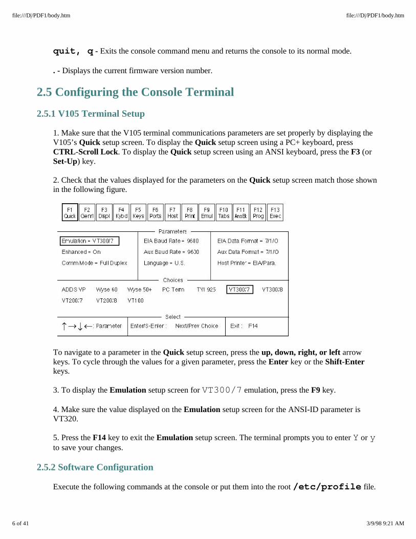
2. Check that the values displayed for the parameters on the Quick setup screen match those shownin the following figure.
To navigate to a parameter in the Quick setup screen, press the up, down, right, or left arrowkeys. To cycle through the values for a given parameter, press the Enter key or the Shift-Enterkeys.
3. To display the Emulation setup screen for VT300/7 emulation, press the F9 key.
4. Make sure the value displayed on the Emulation setup screen for the ANSI-ID parameter isVT320.
5. Press the F14 key to exit the Emulation setup screen. The terminal prompts you to enter Y or yto save your changes.
2.5.2 Software Configuration
Execute the following commands at the console or put them into the root /etc/profile file.
6 of 41 3/9/98 9:21 AM
file:///D|/PDF1/body.htm file:///D|/PDF1/body.htm

TERM=terminal_type export TERM tput init tabs
where TERM establishes the terminal type (e.g., v105), tput initializes the terminal, andtabs sets tabs.
2.6 System Component Locations
Each hardware component configured on a HP-UX system can be identified by its hardware path. Ahardware path specifies the address of the hardware components leading to a device. It consists of anumerical string of hardware addresses, notated sequentially from the bus address to the device address.
2.6.1 Physical Hardware Configuration
The system bus connects the CPU-Memory boards (and corresponding suitcases) with the PCI bridge(PCIB) cards (and associated card cages). The CPU-Memory board (and corresponding suitcase)numbers are 0 and 1. The PCIB (and corresponding card cage) numbers are 2 and 3.
2.6.1.1 CPU-Memory Bus Hardware Paths
The physical CPU-Memory board hardware path addressing convention is as follows:
·First-level address identifies the CPU-Memory board (and corresponding suitcase) numbers (0 or1).
·Second-level address identifies a component on the CPU-Memory board (0 for a CPU module, 1 fora memory module, 2 for the Console Controller).
Examples:
7 of 41 3/9/98 9:21 AM
file:///D|/PDF1/body.htm file:///D|/PDF1/body.htm
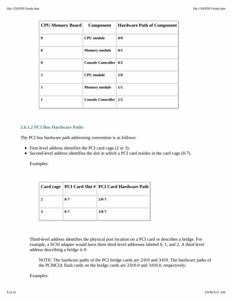
CPU-Memory Board Component Hardware Path of Component
0 CPU module 0/0
0 Memory module 0/1
0 Console Controller 0/2
1 CPU module 1/0
1 Memory module 1/1
1 Console Controller 1/2
2.6.1.2 PCI Bus Hardware Paths
The PCI bus hardware path addressing convention is as follows:
·First-level address identifies the PCI card cage (2 or 3).
·Second-level address identifies the slot in which a PCI card resides in the card cage (0-7).
Examples:
Card cage PCI Card Slot # PCI Card Hardware Path
2 0-7 2/0-7
3 0-7 3/0-7
Third-level address identifies the physical port location on a PCI card or describes a bridge. Forexample, a SCSI adapter would have three third-level addresses labeled 0, 1, and 2. A third-leveladdress describing a bridge is 0.
NOTE: The hardware paths of the PCI bridge cards are 2/0/0 and 3/0/0. The hardware paths ofthe PCMCIA flash cards on the bridge cards are 2/0/0.0 and 3/0/0.0, respectively.
Examples:
8 of 41 3/9/98 9:21 AM
file:///D|/PDF1/body.htm file:///D|/PDF1/body.htm
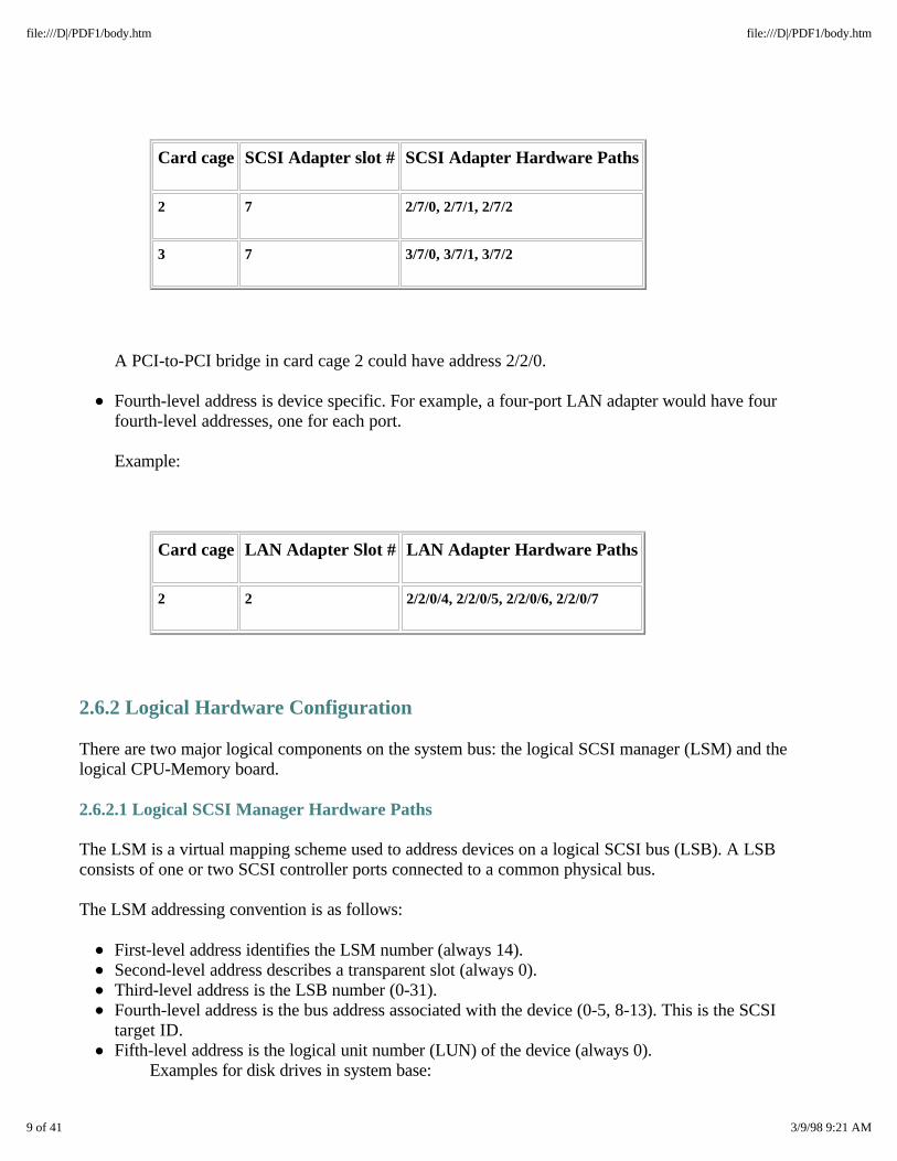
Card cage SCSI Adapter slot # SCSI Adapter Hardware Paths
2 7 2/7/0, 2/7/1, 2/7/2
3 7 3/7/0, 3/7/1, 3/7/2
A PCI-to-PCI bridge in card cage 2 could have address 2/2/0.
·Fourth-level address is device specific. For example, a four-port LAN adapter would have fourfourth-level addresses, one for each port.
Example:
Card cage LAN Adapter Slot # LAN Adapter Hardware Paths
2 2 2/2/0/4, 2/2/0/5, 2/2/0/6, 2/2/0/7
2.6.2 Logical Hardware Configuration
There are two major logical components on the system bus: the logical SCSI manager (LSM) and thelogical CPU-Memory board.
2.6.2.1 Logical SCSI Manager Hardware Paths
The LSM is a virtual mapping scheme used to address devices on a logical SCSI bus (LSB). A LSBconsists of one or two SCSI controller ports connected to a common physical bus.
The LSM addressing convention is as follows:
·First-level address identifies the LSM number (always 14).
·Second-level address describes a transparent slot (always 0).
·Third-level address is the LSB number (0-31).
·Fourth-level address is the bus address associated with the device (0-5, 8-13). This is the SCSItarget ID.
·Fifth-level address is the logical unit number (LUN) of the device (always 0). Examples for disk drives in system base:
9 of 41 3/9/98 9:21 AM
file:///D|/PDF1/body.htm file:///D|/PDF1/body.htm
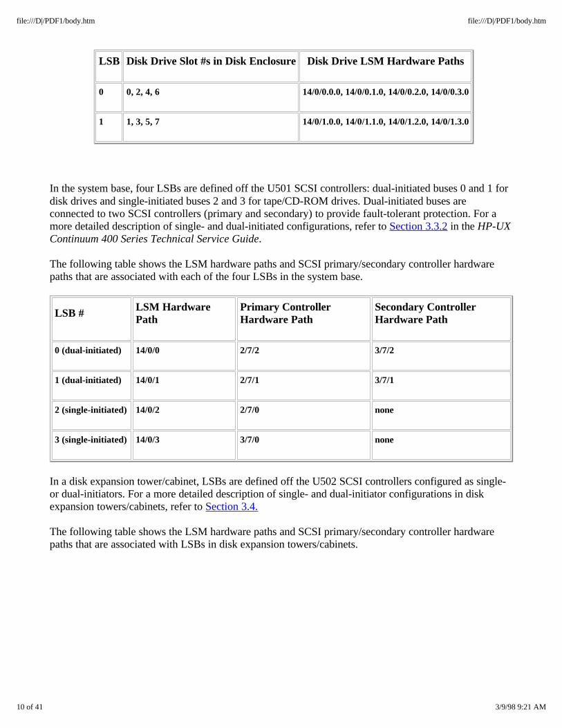
LSB Disk Drive Slot #s in Disk Enclosure Disk Drive LSM Hardware Paths
0 0, 2, 4, 6 14/0/0.0.0, 14/0/0.1.0, 14/0/0.2.0, 14/0/0.3.0
1 1, 3, 5, 7 14/0/1.0.0, 14/0/1.1.0, 14/0/1.2.0, 14/0/1.3.0
In the system base, four LSBs are defined off the U501 SCSI controllers: dual-initiated buses 0 and 1 fordisk drives and single-initiated buses 2 and 3 for tape/CD-ROM drives. Dual-initiated buses areconnected to two SCSI controllers (primary and secondary) to provide fault-tolerant protection. For amore detailed description of single- and dual-initiated configurations, refer to Section 3.3.2 in the HP-UXContinuum 400 Series Technical Service Guide.
The following table shows the LSM hardware paths and SCSI primary/secondary controller hardwarepaths that are associated with each of the four LSBs in the system base.
LSB # LSM HardwarePath
Primary ControllerHardware Path
Secondary ControllerHardware Path
0 (dual-initiated) 14/0/0 2/7/2 3/7/2
1 (dual-initiated) 14/0/1 2/7/1 3/7/1
2 (single-initiated) 14/0/2 2/7/0 none
3 (single-initiated) 14/0/3 3/7/0 none
In a disk expansion tower/cabinet, LSBs are defined off the U502 SCSI controllers configured as single-or dual-initiators. For a more detailed description of single- and dual-initiator configurations in diskexpansion towers/cabinets, refer to Section 3.4.
The following table shows the LSM hardware paths and SCSI primary/secondary controller hardwarepaths that are associated with LSBs in disk expansion towers/cabinets.
10 of 41 3/9/98 9:21 AM
file:///D|/PDF1/body.htm file:///D|/PDF1/body.htm
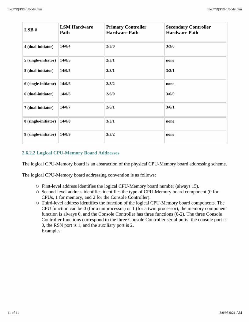
LSB # LSM HardwarePath
Primary ControllerHardware Path
Secondary ControllerHardware Path
4 (dual-initiator) 14/0/4 2/3/0 3/3/0
5 (single-initiator)
5 (dual-initiator)
14/0/5
14/0/5
2/3/1
2/3/1
none
3/3/1
6 (single-initiator)
6 (dual-initiator)
14/0/6
14/0/6
2/3/2
2/6/0
none
3/6/0
7 (dual-initiator) 14/0/7 2/6/1 3/6/1
8 (single-initiator) 14/0/8 3/3/1 none
9 (single-initiator) 14/0/9 3/3/2 none
2.6.2.2 Logical CPU-Memory Board Addresses
The logical CPU-Memory board is an abstraction of the physical CPU-Memory board addressing scheme.
The logical CPU-Memory board addressing convention is as follows:
o First-level address identifies the logical CPU-Memory board number (always 15). o Second-level address identifies identifies the type of CPU-Memory board component (0 for
CPUs, 1 for memory, and 2 for the Console Controller). o Third-level address identifies the function of the logical CPU-Memory board components. The
CPU function can be 0 (for a uniprocessor) or 1 (for a twin processor), the memory componentfunction is always 0, and the Console Controller has three functions (0-2). The three ConsoleController functions correspond to the three Console Controller serial ports: the console port is0, the RSN port is 1, and the auxiliary port is 2. Examples:
11 of 41 3/9/98 9:21 AM
file:///D|/PDF1/body.htm file:///D|/PDF1/body.htm
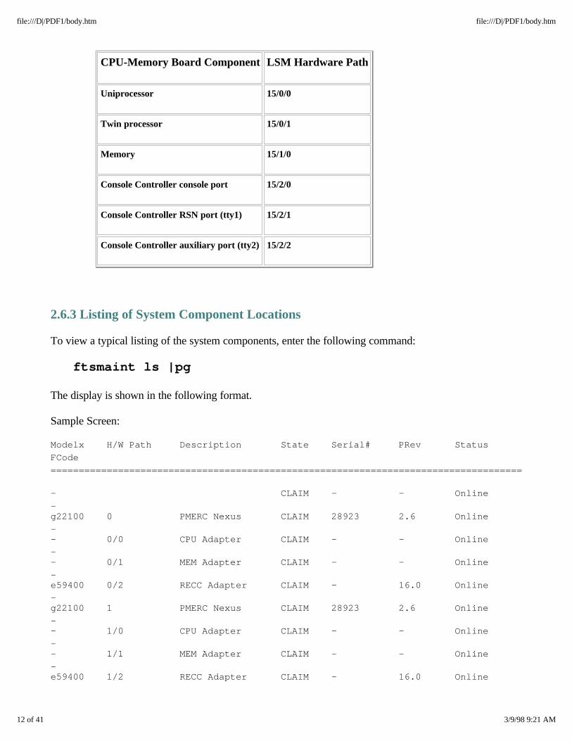
CPU-Memory Board Component LSM Hardware Path
Uniprocessor 15/0/0
Twin processor 15/0/1
Memory 15/1/0
Console Controller console port 15/2/0
Console Controller RSN port (tty1) 15/2/1
Console Controller auxiliary port (tty2) 15/2/2
2.6.3 Listing of System Component Locations
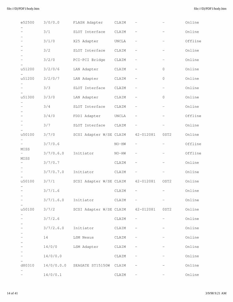
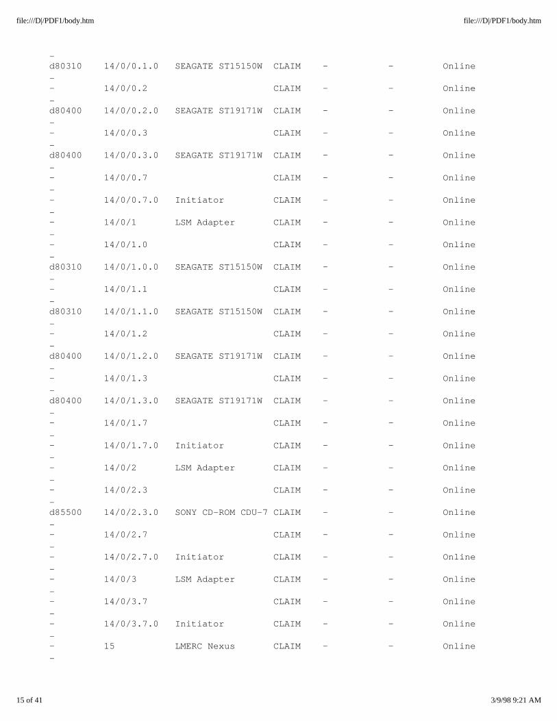
To view a typical listing of the system components, enter the following command:
ftsmaint ls |pg
The display is shown in the following format.
Sample Screen:
Modelx H/W Path Description State Serial# PRev Status
FCode =========================================================================================
- CLAIM - - Online
- g22100 0 PMERC Nexus CLAIM 28923 2.6 Online
- - 0/0 CPU Adapter CLAIM - - Online
- - 0/1 MEM Adapter CLAIM - - Online
- e59400 0/2 RECC Adapter CLAIM - 16.0 Online
- g22100 1 PMERC Nexus CLAIM 28923 2.6 Online
- - 1/0 CPU Adapter CLAIM - - Online
- - 1/1 MEM Adapter CLAIM - - Online
- e59400 1/2 RECC Adapter CLAIM - 16.0 Online
12 of 41 3/9/98 9:21 AM
file:///D|/PDF1/body.htm file:///D|/PDF1/body.htm

- k13800 2 PCI Nexus CLAIM 11073 6553 Online
- - 2/0 SLOT Interface CLAIM - - Online
- unknow 2/0/0 PCMCIA Bridge CLAIM - - Online
- e52500 2/0/0.0 FLASH Adapter CLAIM - - Online
- - 2/1 SLOT Interface CLAIM - - Online
- - 2/1/0 X25 Adapter UNCLA - - Offline
- - 2/2 SLOT Interface CLAIM - - Online
- - 2/2/0 PCI-PCI Bridge CLAIM - - Online
- u51200 2/2/0/6 LAN Adapter CLAIM - 0 Online
- u51200 2/2/0/7 LAN Adapter CLAIM - 0 Online
- - 2/3 SLOT Interface CLAIM - - Online
- u51300 2/3/0 LAN Adapter CLAIM - 0 Online
- - 2/4 SLOT Interface CLAIM - - Online
- - 2/4/0 FDDI Adapter UNCLA - - Offline
- - 2/7 SLOT Interface CLAIM - - Online
- u50100 2/7/0 SCSI Adapter W/SE CLAIM 42-012157 0ST2 Online
- - 2/7/0.7 CLAIM - - Online
- - 2/7/0.7.0 Initiator CLAIM - - Online
- u50100 2/7/1 SCSI Adapter W/SE CLAIM 42-012157 OST2 Online
- - 2/7/1.7 CLAIM - - Online
- - 2/7/1.7.0 Initiator CLAIM - - Online
- u50100 2/7/2 SCSI Adapter W/SE CLAIM 42-012157 0ST2 Online
- - 2/7/2.7 CLAIM - - Online
- - 2/7/2.7.0 Initiator CLAIM - - Online
- k13800 3 PCI Nexus CLAIM 11135 6553 Online
- - 3/0 SLOT Interface CLAIM - - Online
- unknow 3/0/0 PCMCIA Bridge CLAIM - - Online
-
13 of 41 3/9/98 9:21 AM
file:///D|/PDF1/body.htm file:///D|/PDF1/body.htm
e52500 3/0/0.0 FLASH Adapter CLAIM - - Online
- - 3/1 SLOT Interface CLAIM - - Online
- - 3/1/0 X25 Adapter UNCLA - - Offline
- - 3/2 SLOT Interface CLAIM - - Online
- - 3/2/0 PCI-PCI Bridge CLAIM - - Online
- u51200 3/2/0/6 LAN Adapter CLAIM - 0 Online
- u51200 3/2/0/7 LAN Adapter CLAIM - 0 Online
- - 3/3 SLOT Interface CLAIM - - Online
- u51300 3/3/0 LAN Adapter CLAIM - 0 Online
- - 3/4 SLOT Interface CLAIM - - Online
- - 3/4/0 FDDI Adapter UNCLA - - Offline
- - 3/7 SLOT Interface CLAIM - - Online
- u50100 3/7/0 SCSI Adapter W/SE CLAIM 42-012081 0ST2 Online
- - 3/7/0.6 NO-HW - - Offline
MISS - 3/7/0.6.0 Initiator NO-HW - - Offline
MISS - 3/7/0.7 CLAIM - - Online
- - 3/7/0.7.0 Initiator CLAIM - - Online
- u50100 3/7/1 SCSI Adapter W/SE CLAIM 42-012081 OST2 Online
- - 3/7/1.6 CLAIM - - Online
- - 3/7/1.6.0 Initiator CLAIM - - Online
- u50100 3/7/2 SCSI Adapter W/SE CLAIM 42-012081 0ST2 Online
- - 3/7/2.6 CLAIM - - Online
- - 3/7/2.6.0 Initiator CLAIM - - Online
- - 14 LSM Nexus CLAIM - - Online
- - 14/0/0 LSM Adapter CLAIM - - Online
- - 14/0/0.0 CLAIM - - Online
- d80310 14/0/0.0.0 SEAGATE ST15150W CLAIM - - Online
- - 14/0/0.1 CLAIM - - Online
14 of 41 3/9/98 9:21 AM
file:///D|/PDF1/body.htm file:///D|/PDF1/body.htm
- d80310 14/0/0.1.0 SEAGATE ST15150W CLAIM - - Online
- - 14/0/0.2 CLAIM - - Online
- d80400 14/0/0.2.0 SEAGATE ST19171W CLAIM - - Online
- - 14/0/0.3 CLAIM - - Online
- d80400 14/0/0.3.0 SEAGATE ST19171W CLAIM - - Online
- - 14/0/0.7 CLAIM - - Online
- - 14/0/0.7.0 Initiator CLAIM - - Online
- - 14/0/1 LSM Adapter CLAIM - - Online
- - 14/0/1.0 CLAIM - - Online
- d80310 14/0/1.0.0 SEAGATE ST15150W CLAIM - - Online
- - 14/0/1.1 CLAIM - - Online
- d80310 14/0/1.1.0 SEAGATE ST15150W CLAIM - - Online
- - 14/0/1.2 CLAIM - - Online
- d80400 14/0/1.2.0 SEAGATE ST19171W CLAIM - - Online
- - 14/0/1.3 CLAIM - - Online
- d80400 14/0/1.3.0 SEAGATE ST19171W CLAIM - - Online
- - 14/0/1.7 CLAIM - - Online
- - 14/0/1.7.0 Initiator CLAIM - - Online
- - 14/0/2 LSM Adapter CLAIM - - Online
- - 14/0/2.3 CLAIM - - Online
- d85500 14/0/2.3.0 SONY CD-ROM CDU-7 CLAIM - - Online
- - 14/0/2.7 CLAIM - - Online
- - 14/0/2.7.0 Initiator CLAIM - - Online
- - 14/0/3 LSM Adapter CLAIM - - Online
- - 14/0/3.7 CLAIM - - Online
- - 14/0/3.7.0 Initiator CLAIM - - Online
- - 15 LMERC Nexus CLAIM - - Online
-
15 of 41 3/9/98 9:21 AM
file:///D|/PDF1/body.htm file:///D|/PDF1/body.htm
- 15/0/0 Processor CLAIM - - Online
- - 15/0/1 Processor CLAIM - - Online
- - 15/1/0 Memory CLAIM - - Online
- - 15/2/0 console CLAIM - - Online
- - 15/2/1 tty1 CLAIM - - Online
- - 15/2/2 tty2 CLAIM - - Online
-
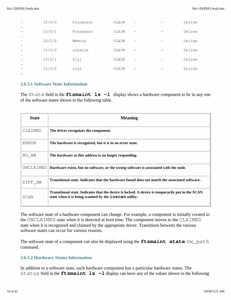
2.6.3.1 Software State Information
The State field in the ftsmaint ls -l display shows a hardware component to be in any oneof the software states shown in the following table.
State Meaning
CLAIMED The driver recognizes the component.
ERROR The hardware is recognized, but it is in an error state.
NO_HW The hardware at this address is no longer responding.
UNCLAIMED Hardware exists, but no software, or the wrong software is associated with the node.
DIFF_HW Transitional state. Indicates that the hardware found does not match the associated software.
SCANTransitional state. Indicates that the device is locked. A device is temporarily put in the SCANstate when it is being scanned by the ioscan utility.
The software state of a hardware component can change. For example, a component is initially created inthe UNCLAIMED state when it is detected at boot time. The component moves to the CLAIMEDstate when it is recognized and claimed by the appropriate driver. Transitions between the varioussoftware states can occur for various reasons.
The software state of a component can also be displayed using the ftsmaint state hw_pathcommand.
2.6.3.2 Hardware Status Information
In addition to a software state, each hardware component has a particular hardware status. TheStatus field in the ftsmaint ls -l display can have any of the values shown in the following
16 of 41 3/9/98 9:21 AM
file:///D|/PDF1/body.htm file:///D|/PDF1/body.htm
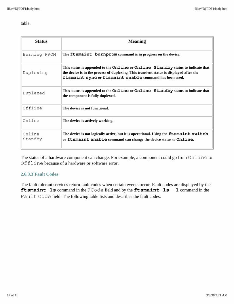
table.
Status Meaning
Burning PROM The ftsmaint burnprom command is in progress on the device.
DuplexingThis status is appended to the Online or Online Standby status to indicate thatthe device is in the process of duplexing. This transient status is displayed after theftsmaint sync or ftsmaint enable command has been used.
Duplexed This status is appended to the Online or Online Standby status to indicate thatthe component is fully duplexed.
Offline The device is not functional.
Online The device is actively working.
OnlineStandby
The device is not logically active, but it is operational. Using the ftsmaint switchor ftsmaint enable command can change the device status to Online.
The status of a hardware component can change. For example, a component could go from Online toOffline because of a hardware or software error.
2.6.3.3 Fault Codes
The fault tolerant services return fault codes when certain events occur. Fault codes are displayed by theftsmaint ls command in the FCode field and by the ftsmaint ls -l command in the
Fault Code field. The following table lists and describes the fault codes.
17 of 41 3/9/98 9:21 AM
file:///D|/PDF1/body.htm file:///D|/PDF1/body.htm
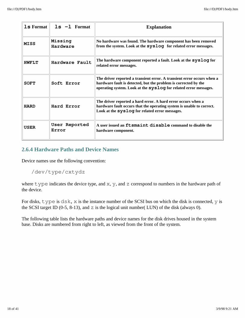
ls Format ls -l Format Explanation
MISSMissingHardware
No hardware was found. The hardware component has been removedfrom the system. Look at the syslog for related error messages.
HWFLT Hardware Fault The hardware component reported a fault. Look at the syslog forrelated error messages.
SOFT Soft ErrorThe driver reported a transient error. A transient error occurs when ahardware fault is detected, but the problem is corrected by theoperating system. Look at the syslog for related error messages.
HARD Hard ErrorThe driver reported a hard error. A hard error occurs when ahardware fault occurs that the operating system is unable to correct.Look at the syslog for related error messages.
USERUser ReportedError
A user issued an ftsmaint disable command to disable thehardware component.
2.6.4 Hardware Paths and Device Names
Device names use the following convention:
/dev/type/cxtydz
where type indicates the device type, and x, y, and z correspond to numbers in the hardware path ofthe device.
For disks, type is dsk, x is the instance number of the SCSI bus on which the disk is connected, y isthe SCSI target ID (0-5, 8-13), and z is the logical unit number( LUN) of the disk (always 0).
The following table lists the hardware paths and device names for the disk drives housed in the systembase. Disks are numbered from right to left, as viewed from the front of the system.
18 of 41 3/9/98 9:21 AM
file:///D|/PDF1/body.htm file:///D|/PDF1/body.htm
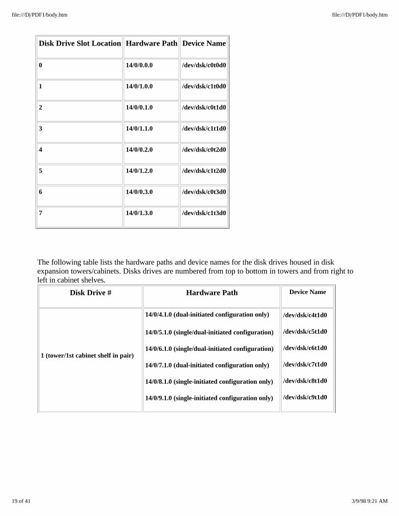
Disk Drive Slot Location Hardware Path Device Name
0 14/0/0.0.0 /dev/dsk/c0t0d0
1 14/0/1.0.0 /dev/dsk/c1t0d0
2 14/0/0.1.0 /dev/dsk/c0t1d0
3 14/0/1.1.0 /dev/dsk/c1t1d0
4 14/0/0.2.0 /dev/dsk/c0t2d0
5 14/0/1.2.0 /dev/dsk/c1t2d0
6 14/0/0.3.0 /dev/dsk/c0t3d0
7 14/0/1.3.0 /dev/dsk/c1t3d0
The following table lists the hardware paths and device names for the disk drives housed in diskexpansion towers/cabinets. Disks drives are numbered from top to bottom in towers and from right toleft in cabinet shelves.
Disk Drive # Hardware Path Device Name
1 (tower/1st cabinet shelf in pair)
14/0/4.1.0 (dual-initiated configuration only)
14/0/5.1.0 (single/dual-initiated configuration)
14/0/6.1.0 (single/dual-initiated configuration)
14/0/7.1.0 (dual-initiated configuration only)
14/0/8.1.0 (single-initiated configuration only)
14/0/9.1.0 (single-initiated configuration only)
/dev/dsk/c4t1d0
/dev/dsk/c5t1d0
/dev/dsk/c6t1d0
/dev/dsk/c7t1d0
/dev/dsk/c8t1d0
/dev/dsk/c9t1d0
19 of 41 3/9/98 9:21 AM
file:///D|/PDF1/body.htm file:///D|/PDF1/body.htm
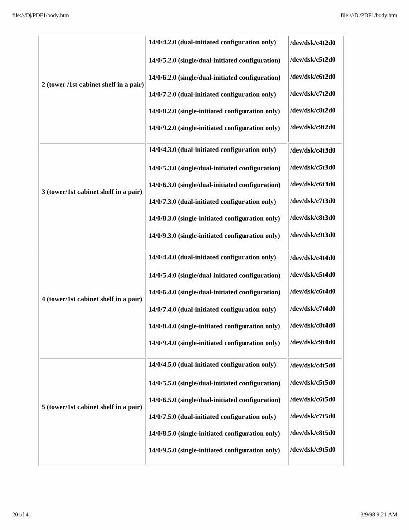
2 (tower /1st cabinet shelf in a pair)
14/0/4.2.0 (dual-initiated configuration only)
14/0/5.2.0 (single/dual-initiated configuration)
14/0/6.2.0 (single/dual-initiated configuration)
14/0/7.2.0 (dual-initiated configuration only)
14/0/8.2.0 (single-initiated configuration only)
14/0/9.2.0 (single-initiated configuration only)
/dev/dsk/c4t2d0
/dev/dsk/c5t2d0
/dev/dsk/c6t2d0
/dev/dsk/c7t2d0
/dev/dsk/c8t2d0
/dev/dsk/c9t2d0
3 (tower/1st cabinet shelf in a pair)
14/0/4.3.0 (dual-initiated configuration only)
14/0/5.3.0 (single/dual-initiated configuration)
14/0/6.3.0 (single/dual-initiated configuration)
14/0/7.3.0 (dual-initiated configuration only)
14/0/8.3.0 (single-initiated configuration only)
14/0/9.3.0 (single-initiated configuration only)
/dev/dsk/c4t3d0
/dev/dsk/c5t3d0
/dev/dsk/c6t3d0
/dev/dsk/c7t3d0
/dev/dsk/c8t3d0
/dev/dsk/c9t3d0
4 (tower/1st cabinet shelf in a pair)
14/0/4.4.0 (dual-initiated configuration only)
14/0/5.4.0 (single/dual-initiated configuration)
14/0/6.4.0 (single/dual-initiated configuration)
14/0/7.4.0 (dual-initiated configuration only)
14/0/8.4.0 (single-initiated configuration only)
14/0/9.4.0 (single-initiated configuration only)
/dev/dsk/c4t4d0
/dev/dsk/c5t4d0
/dev/dsk/c6t4d0
/dev/dsk/c7t4d0
/dev/dsk/c8t4d0
/dev/dsk/c9t4d0
5 (tower/1st cabinet shelf in a pair)
14/0/4.5.0 (dual-initiated configuration only)
14/0/5.5.0 (single/dual-initiated configuration)
14/0/6.5.0 (single/dual-initiated configuration)
14/0/7.5.0 (dual-initiated configuration only)
14/0/8.5.0 (single-initiated configuration only)
14/0/9.5.0 (single-initiated configuration only)
/dev/dsk/c4t5d0
/dev/dsk/c5t5d0
/dev/dsk/c6t5d0
/dev/dsk/c7t5d0
/dev/dsk/c8t5d0
/dev/dsk/c9t5d0
20 of 41 3/9/98 9:21 AM
file:///D|/PDF1/body.htm file:///D|/PDF1/body.htm
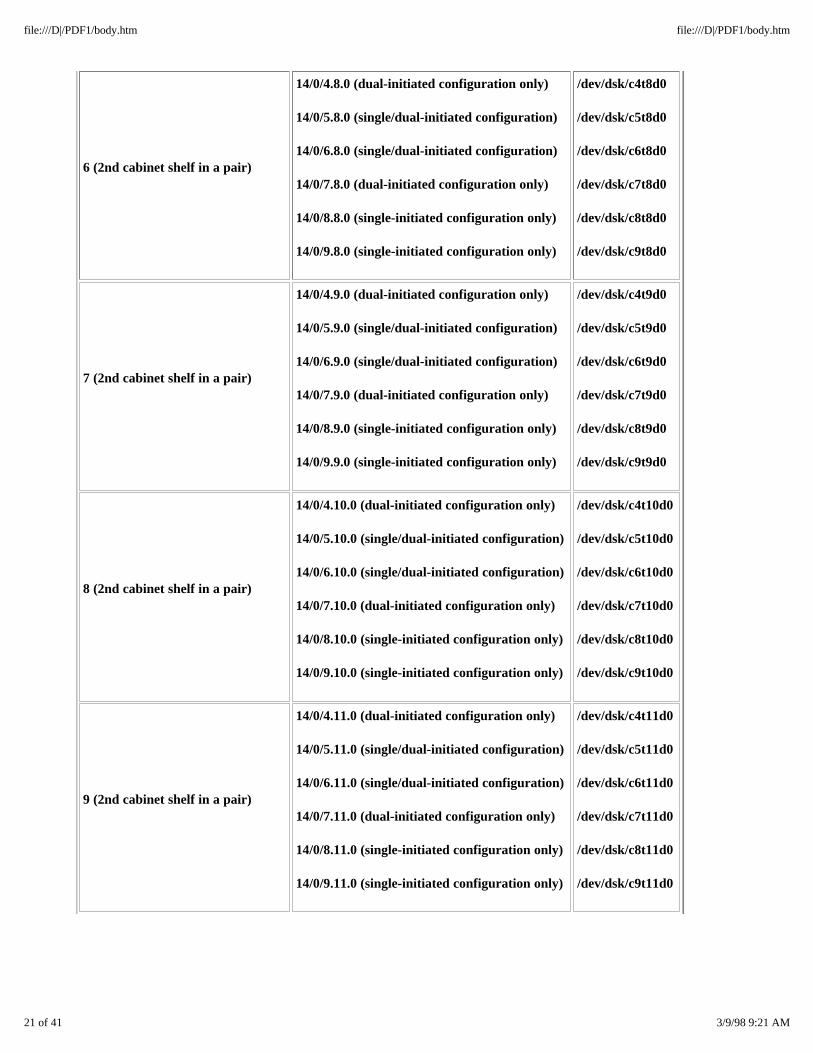
6 (2nd cabinet shelf in a pair)
14/0/4.8.0 (dual-initiated configuration only)
14/0/5.8.0 (single/dual-initiated configuration)
14/0/6.8.0 (single/dual-initiated configuration)
14/0/7.8.0 (dual-initiated configuration only)
14/0/8.8.0 (single-initiated configuration only)
14/0/9.8.0 (single-initiated configuration only)
/dev/dsk/c4t8d0
/dev/dsk/c5t8d0
/dev/dsk/c6t8d0
/dev/dsk/c7t8d0
/dev/dsk/c8t8d0
/dev/dsk/c9t8d0
7 (2nd cabinet shelf in a pair)
14/0/4.9.0 (dual-initiated configuration only)
14/0/5.9.0 (single/dual-initiated configuration)
14/0/6.9.0 (single/dual-initiated configuration)
14/0/7.9.0 (dual-initiated configuration only)
14/0/8.9.0 (single-initiated configuration only)
14/0/9.9.0 (single-initiated configuration only)
/dev/dsk/c4t9d0
/dev/dsk/c5t9d0
/dev/dsk/c6t9d0
/dev/dsk/c7t9d0
/dev/dsk/c8t9d0
/dev/dsk/c9t9d0
8 (2nd cabinet shelf in a pair)
14/0/4.10.0 (dual-initiated configuration only)
14/0/5.10.0 (single/dual-initiated configuration)
14/0/6.10.0 (single/dual-initiated configuration)
14/0/7.10.0 (dual-initiated configuration only)
14/0/8.10.0 (single-initiated configuration only)
14/0/9.10.0 (single-initiated configuration only)
/dev/dsk/c4t10d0
/dev/dsk/c5t10d0
/dev/dsk/c6t10d0
/dev/dsk/c7t10d0
/dev/dsk/c8t10d0
/dev/dsk/c9t10d0
9 (2nd cabinet shelf in a pair)
14/0/4.11.0 (dual-initiated configuration only)
14/0/5.11.0 (single/dual-initiated configuration)
14/0/6.11.0 (single/dual-initiated configuration)
14/0/7.11.0 (dual-initiated configuration only)
14/0/8.11.0 (single-initiated configuration only)
14/0/9.11.0 (single-initiated configuration only)
/dev/dsk/c4t11d0
/dev/dsk/c5t11d0
/dev/dsk/c6t11d0
/dev/dsk/c7t11d0
/dev/dsk/c8t11d0
/dev/dsk/c9t11d0
21 of 41 3/9/98 9:21 AM
file:///D|/PDF1/body.htm file:///D|/PDF1/body.htm

10 (2nd cabinet shelf in a pair)
14/0/4.12.0 (dual-initiated configuration only)
14/0/5.12.0 (single/dual-initiated configuration)
14/0/6.12.0 (single/dual-initiated configuration)
14/0/7.12.0 (dual-initiated configuration only)
14/0/8.12.0 (single-initiated configuration only)
14/0/9.12.0 (single-initiated configuration only)
/dev/dsk/c4t12d0
/dev/dsk/c5t12d0
/dev/dsk/c6t12d0
/dev/dsk/c7t12d0
/dev/dsk/c8t12d0
/dev/dsk/c9t12d0
11 (2nd cabinet shelf in a pair)
14/0/4.13.0 (dual-initiated configuration only)
14/0/5.13.0 (single/dual-initiated configuration)
14/0/6.13.0 (single/dual-initiated configuration)
14/0/7.13.0 (dual-initiated configuration only)
14/0/8.13.0 (single-initiated configuration only)
14/0/9.13.0 (single-initiated configuration only)
/dev/dsk/c4t13d0
/dev/dsk/c5t13d0
/dev/dsk/c6t13d0
/dev/dsk/c7t13d0
/dev/dsk/c8t13d0
/dev/dsk/c9t13d0
For flash cards, type is rflash, x is the PCI card cage number (2 or 3), and y and z are always0.
Example:
Card cage Flashcard Hardware Path Device Name
2 2/0/0.0 /dev/rflash/c2a0d0
3 3/0/0.0 /dev/rflash/c3a0d0
22 of 41 3/9/98 9:21 AM
file:///D|/PDF1/body.htm file:///D|/PDF1/body.htm

Examples of CD-ROM and tape drive hardware paths and device names are shown in the followingtable.
Device Physical Hardware Path Device NameLogical Hardware Path
CD-ROM drive 2/7/0 /dev/dsk/c2/t3d0 14/0/2.3.0
Tape drive 3/7/0 /dev/tape/c3/t0d0 14/0/3.0.0
2.7 Maintenance Procedures
When the system boots up, the operating system checks each hardware path to determine whether aCRU/FRU component is present and to record the model number of each component it finds. Eachcomponent is added automatically to that hardware path, and component maintenance is initiated.Maintenance performed by the operating system includes the following:
o Attempting recovery if the component suffers transient failures o Responding to maintenance commands o Making the components's resources available to the operating system o Logging changes in the component's status o Supplying the components's status o Supplying the component's state on demand
During normal operation, the operating system periodically checks each hardware path. If a component isnot operating, is missing, or is the wrong model number for that hardware path's definition, messages areissued to the system log and console.
Replacing or deleting some components requires only that the unit be inserted or removed from thesystem. Other removal/replacement procedures require that software commands be entered. The primaryhardware maintenance utility is the ftsmaint command which is used for many tasks, including thefollowing:
o Determining hardware paths o Displaying software state information o Removing and replacing hardware components o Resetting devices o Displaying and managing MTBF (mean time between failures) statistics o Burning PROM code
The addhardware command is use to add hardware components to a running system. Itautomatically runs the system utilities needed to remake the kernel, bring the new device online, and writethe ioconfig file back to the flash card.
23 of 41 3/9/98 9:21 AM
file:///D|/PDF1/body.htm file:///D|/PDF1/body.htm

This section provides a set of software procedures used to maintain the system, including commands toprepare a unit for removal and verifying that the component is operating after replacement, and addingnew hardware components. Since most hardware components in a HP-UX Continuum 400 Series systemare customer replaceable, the physical removal/replacement procedures for CRUs are not described inthis manual. Refer to the Continuum 400 Series: Operation and Maintenance for the HP-UX OperatingSystem (R001H-02) for detailed information on removing and replacing CRUs. For tape drivemaintenance, refer to Continuum 400 Series: Tape-Drive Operation for the HP-UX Operating System(R003H).
2.7.1 Removal and Replacement
Note: If a device is in the ERROR state, try to reset it before removing and replacing it. Usethe ftsmaint reset hw_path command to reset the device, and then the
ftsmaint enable hw_path command to enable it.
2.7.1.1 Preparing to Remove a Suitcase
A defective suitcase is hot pluggable (can be replaced without disrupting the system or entering anycommands). Make sure it is duplexed (its amber LED is on, and the yellow and green LEDs are off).Verify its location and state/status as follows:
1. Note the number (either 0 or 1) on the front label of the failed suitcase.
2. Enter the following command to verify the state and status of the suitcase:
ftsmaint ls hw_path
where hw_path is the number on the suitcase front label (0 or 1).
The information in the State and Status fields of the display will show information onthe failed suitcase.
2.7.1.2 Verifying Suitcase Operation
After the replacement suitcase is installed, the system automatically tests it and duplexes it with the othersuitcase. When testing is complete, the amber LED will turn off and the green LED will come on.Perform the following to verify proper operation of the suitcase:
1. Enter the ftsmaint ls hw_path command.
where hw_path is the hardware path of the suitcase (0 or 1).
2. Verify that the replacement suitcase is now operational by checking the State and Statusfields. While the suitcase is coming online, its state should be listed as Duplexing and the statusshould be listed as Offline. When duplexing is complete, its State field should be listed asCLAIMED and the Status field should be listed as Online.
When the suitcase is online, its green LED is on steadily.
24 of 41 3/9/98 9:21 AM
file:///D|/PDF1/body.htm file:///D|/PDF1/body.htm
3. Enter the following command to update the date to ensure that it is the same on both ConsoleControllers.
date mmddhhMM[yy]
where mm specifies the month, dd is the day of the month, hh is the hour (24-hour system), MM isthe minute, and yy is the last two digits of the year.
NOTE: All new or replacement boards come with the latest PROM code already installed.Therefore, it is not necessary to burn the PROM of any new hardware. However, if onlyone suitcase is replaced, it might be necessary to burn the PROM on the ConsoleController in the "old" suitcase to match the Console Controller in the replacementsuitcase. Burning the PROM code on the Console Controller is described in Section2.7.3.2.
2.7.1.3 Preparing to Remove a PCI Card
When an I/O card cage is opened, its PCI bus is automatically powered down and all PCI cards housedwithin the card cage are logically removed from the system. Before opening the card cage, verify thelocation and state of the failed PCI card as follows:
1. Check the LEDs on the PCI card cage slot where the PCI card is located.
2. If the red LED is on, enter the following command:
ftsmaint ls
The information in the State and Status fields of the display will show information onthe failed PCI card. The state will be ERROR and the status will be Offline.
3. Disable the PCI card by entering the following command:
ftsmaint disable hw_path
where hw_path is the hardware path of the PCI card. (2/x or 3/x, where 2 or 3 is thecard cage and x is the slot number within the card cage (0-7).
2.7.1.4 Enabling a PCI Card and Verifying its Operation
After the replacement PCI card is installed and the card cage door is closed, the system automaticallytests and brings all the cards in that card cage online.
1. Enable the new PCI card by entering the following command:
ftsmaint enable hw_path
where hw_path is the hardware path of the PCI card (2/x or 3/x, where 2 or 3 is the card
25 of 41 3/9/98 9:21 AM
file:///D|/PDF1/body.htm file:///D|/PDF1/body.htm
cage and x is the slot number within the card cage (0-7).
2. When the PCI card comes online, its green LED (and all the other PCI card green LEDs inthe card cage) will be on. To further verify that the replacement PCI card is functioningproperly, enter the following command:
ftsmaint ls hw_path
3. Check the State and Status fields. The State field should be listed as CLAIMED andthe Status field should be listed as Online.
2.7.1.5 Preparing to Remove a Flash Card
The flash card is hot pluggable (can be removed without entering any commands). However, you shouldverify its location as follows.
1. Enter the following command:
ftsmaint ls
2. Determine the hardware path of the flash card to be removed (2/0/0.0 or 3/0/0.0).
The information in the State and Status fields of the display will show information on thefailed flash card.
2.7.1.6 Verifying Flash Card Replacement
1. To verify proper operation of the flash card, enter the following command:
ftsmaint ls hw_path
where hw_path is the hardware path of the flash card (2/0/0.0 or 3/0/0.0).
2. Check the State and Status fields. The State field should be listed as CLAIMEDand the Status field should be listed as Online.
3. To write the current version of the /stand directory to the new flash card, refer toSection 2.7.3.2.
2.7.1.7 Preparing to Remove a Disk Drive
A disk drive is hot pluggable (can be removed without entering any commands) if its amber LED isblinking. However, you should verify its location and status using the following procedure.
1. Determine the hardware path and path name of the disk to be replaced. Refer to Section 2.6.4 fora complete listing of the hardware paths and device names of the disk drives.
2. Check the state of the disk drive to be replaced by entering the following command:
26 of 41 3/9/98 9:21 AM
file:///D|/PDF1/body.htm file:///D|/PDF1/body.htm
ftsmaint ls hw_path
where where hw_path is the hardware path of the disk drive to be replaced.
If the disk is being replaced because of a disk failure (State field is listed as ERROR) go toStep 6. Otherwise, continue with Step 3.
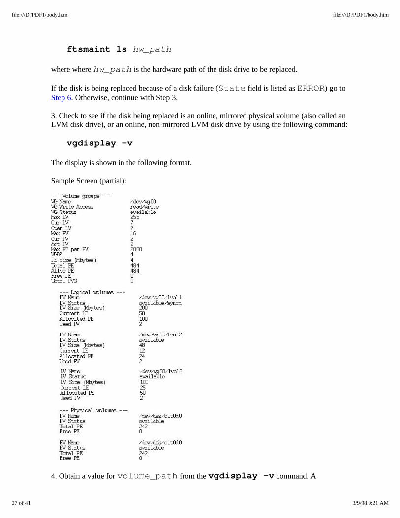
3. Check to see if the disk being replaced is an online, mirrored physical volume (also called anLVM disk drive), or an online, non-mirrored LVM disk drive by using the following command:
vgdisplay -v
The display is shown in the following format.
Sample Screen (partial):
4. Obtain a value for volume_path from the vgdisplay -v command. A
27 of 41 3/9/98 9:21 AM
file:///D|/PDF1/body.htm file:///D|/PDF1/body.htm
volume_path in the above display is /dev/vg00/lvo11.
5. Enter the following command to determine if the disk being replaced is mirrored:
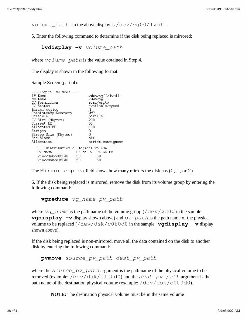
lvdisplay -v volume_path
where volume_path is the value obtained in Step 4.
The display is shown in the following format.
Sample Screen (partial):
The Mirror copies field shows how many mirrors the disk has (0, 1, or 2).
6. If the disk being replaced is mirrored, remove the disk from its volume group by entering thefollowing command:
vgreduce vg_name pv_path
where vg_name is the path name of the volume group (/dev/vg00 in the samplevgdisplay -v display shown above) and pv_path is the path name of the physicalvolume to be replaced (/dev/dsk/c0t0d0 in the sample vgdisplay -v displayshown above).
If the disk being replaced is non-mirrored, move all the data contained on the disk to anotherdisk by entering the following command:
pvmove source_pv_path dest_pv_path
where the source_pv_path argument is the path name of the physical volume to beremoved (example: /dev/dsk/c1t0d0) and the dest_pv_path argument is thepath name of the destination physical volume (example: /dev/dsk/c0t0d0).
NOTE: The destination physical volume must be in the same volume
28 of 41 3/9/98 9:22 AM
file:///D|/PDF1/body.htm file:///D|/PDF1/body.htm
group as the source physical volume.
2.7.1.8 Verifying Disk Drive Replacement
After the replacement disk drive is installed, the system automatically tests it and brings it online. Thedisk is online and ready when the amber LED stops blinking.
1. Verify that the replacement disk is operational by entering the following command:
ftsmaint ls hw_path
where where hw_path is the hardware path of the disk drive.
2. Check the State and Status fields. The State field should be listed as CLAIMEDand the Status field should be listed as Online.
3. If the disk that was replaced was an online, non-mirrored LVM disk, restore data to the newdisk by entering the following command:
pvmove source_pv_path dest_pv_path
where the source_pv_path argument is the path name of thephysical volume where the data resides (example:/dev/dsk/c1t0d0) and the dest_pv_path argument is thepath name of the new physical volume (example:/dev/dsk/c0t0d0).
4. If the disk that was replaced was an online, mirrored LVM disk, perform the following stepsto ensure that the data on the replacement disk is both synchronized and valid.
a. Use the vgcfgrestore command to restore LVM configuration informationto the new disk.
b. Use the vgchange -a -y command to reactivate the volume group towhich the disk belongs.
c. Use the vgsync command to manually synchronize all the extents in the volumegroup.
5. If a failed disk was replaced, restore any volumes that were disabled by the disk drive failure.
For more information on commands pertaining to disk maintenance, refer to the manual HP-UXOperating System: Fault Tolerant System Administration (R1004H-01) or HP-UX Operating System:Peripherals Configuration (R1001H-01)
2.7.1.9 Preparing to Remove a Tape Drive
Tape drives are not hot pluggable devices. Perform the following steps to suspend operation on the SCSI
29 of 41 3/9/98 9:22 AM
file:///D|/PDF1/body.htm file:///D|/PDF1/body.htm

bus associated with the failed tape drive.
1. Enter the following command to determine the hardware path of the failed tape drive.
ftsmaint ls
2. Determine the hardware path of the tape drive to be removed (14/0/2 or 14/0/3).
The information in the State and Status fields of the display will show information onthe failed tape drive.
2.7.1.10 Verifying Tape Drive Replacement
1. To verify that the tape drive is online, enter the following command:
ioscan -C tape
The tape drive should be listed as CLAIMED in the S/W State field of the display.
2. To verify that the tape drive is operating properly, issue tape drive operating commands,such as cpio to copy a file to the tape drive, and then copy the same file from the tape driveto the /tmp directory.
2.7.1.11 Preparing to Remove a System Base Power Supply
A system base power supply is hot pluggable (can be removed without entering any commands) if its redLED is on and its partner's amber and green LEDs are on.. However, you should verify its fault status byentering the ftsmaint ls command.
1. Enter the following command to determine the hardware path of the failed power supply.
ftsmaint ls -l hardware_path
where where hardware_path is the hardware path of the failed power supply (either 2or 3). A value other than 0 in the Power Supply Fault Code field indicates thatthe power supply is not working. In addition, if the value of the Power Supply Fan Speed fieldis High, this indicates that the other power supply is not working.
2.7.1.12 Verifying System Base Power Supply Replacement
After the replacement power supply is installed, it is ready and operating properly when the green LED ison. All PCI cards on the same side of the system as the new power supply are automatically brought backonline when the power supply comes online. Their red LEDs should be off.
To verify that the power supply and each associated card are online, enter the following command:
ftsmaint ls -l hardware_path
30 of 41 3/9/98 9:22 AM
file:///D|/PDF1/body.htm file:///D|/PDF1/body.htm
A value of 0 in the Power Supply Fault Code field indicates that the power supply isworking.
2.7.2 Adding New Hardware Components
The following procedure describes how to update the system for a new hardware device.
1. Physically configure the hardware into the system according to the hardware documentation.
2. Power on the device.
3. Enter the following command:
addhardware
The system will scan for the new hardware and make the necessary updates to the system file. Thedevice special files required by the new device will be created in the appropriate /dev directories.
4. Verify the configuration by entering the following command:
ftsmaint ls hw_path
where where hw_path is the hardware path of the device.
2.7.3 Maintaining Flash Cards
The Continuum 400 Series system contains two flash cards which are located on the PCIB card. The flashcards are credit-sized EEPROMs used to boot the operating system.
The following table describes the Logical Interchange Format (LIF) files contained on each flash card:
31 of 41 3/9/98 9:22 AM
file:///D|/PDF1/body.htm file:///D|/PDF1/body.htm
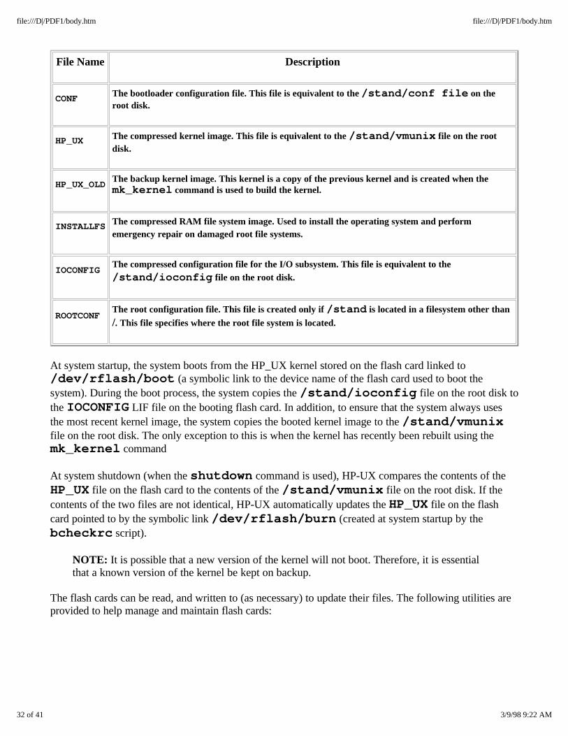
File Name Description
CONF The bootloader configuration file. This file is equivalent to the /stand/conf file on theroot disk.
HP_UX The compressed kernel image. This file is equivalent to the /stand/vmunix file on the rootdisk.
HP_UX_OLDThe backup kernel image. This kernel is a copy of the previous kernel and is created when themk_kernel command is used to build the kernel.
INSTALLFS The compressed RAM file system image. Used to install the operating system and performemergency repair on damaged root file systems.
IOCONFIGThe compressed configuration file for the I/O subsystem. This file is equivalent to the/stand/ioconfig file on the root disk.
ROOTCONFThe root configuration file. This file is created only if /stand is located in a filesystem other than
/. This file specifies where the root file system is located.
At system startup, the system boots from the HP_UX kernel stored on the flash card linked to/dev/rflash/boot (a symbolic link to the device name of the flash card used to boot thesystem). During the boot process, the system copies the /stand/ioconfig file on the root disk tothe IOCONFIG LIF file on the booting flash card. In addition, to ensure that the system always usesthe most recent kernel image, the system copies the booted kernel image to the /stand/vmunixfile on the root disk. The only exception to this is when the kernel has recently been rebuilt using themk_kernel command
At system shutdown (when the shutdown command is used), HP-UX compares the contents of theHP_UX file on the flash card to the contents of the /stand/vmunix file on the root disk. If thecontents of the two files are not identical, HP-UX automatically updates the HP_UX file on the flashcard pointed to by the symbolic link /dev/rflash/burn (created at system startup by thebcheckrc script).
NOTE: It is possible that a new version of the kernel will not boot. Therefore, it is essentialthat a known version of the kernel be kept on backup.
The flash cards can be read, and written to (as necessary) to update their files. The following utilities areprovided to help manage and maintain flash cards:
32 of 41 3/9/98 9:22 AM
file:///D|/PDF1/body.htm file:///D|/PDF1/body.htm
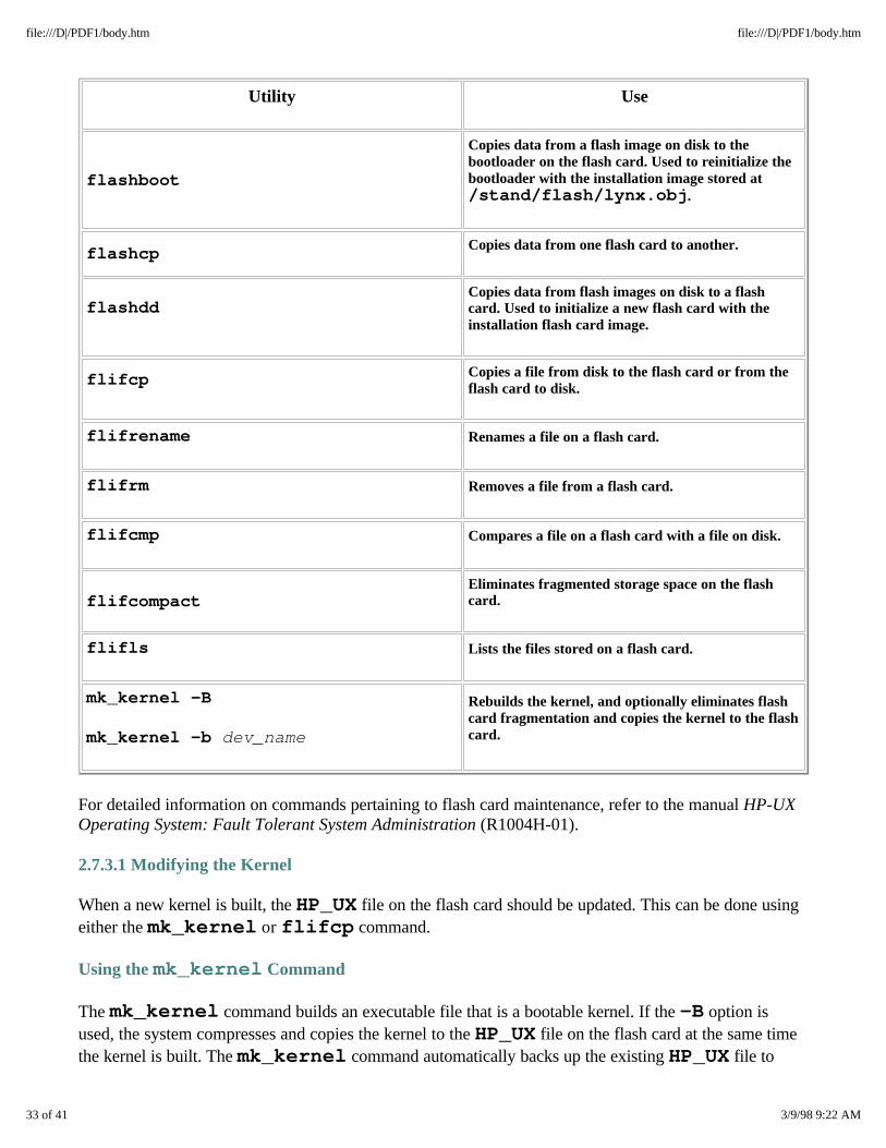
Utility Use
flashboot
Copies data from a flash image on disk to thebootloader on the flash card. Used to reinitialize thebootloader with the installation image stored at/stand/flash/lynx.obj.
flashcp Copies data from one flash card to another.
flashddCopies data from flash images on disk to a flashcard. Used to initialize a new flash card with theinstallation flash card image.
flifcp Copies a file from disk to the flash card or from theflash card to disk.
flifrename Renames a file on a flash card.
flifrm Removes a file from a flash card.
flifcmp Compares a file on a flash card with a file on disk.
flifcompactEliminates fragmented storage space on the flashcard.
flifls Lists the files stored on a flash card.
mk_kernel -B
mk_kernel -b dev_name
Rebuilds the kernel, and optionally eliminates flashcard fragmentation and copies the kernel to the flashcard.
For detailed information on commands pertaining to flash card maintenance, refer to the manual HP-UXOperating System: Fault Tolerant System Administration (R1004H-01).
2.7.3.1 Modifying the Kernel
When a new kernel is built, the HP_UX file on the flash card should be updated. This can be done usingeither the mk_kernel or flifcp command.
Using the mk_kernel Command
The mk_kernel command builds an executable file that is a bootable kernel. If the -B option isused, the system compresses and copies the kernel to the HP_UX file on the flash card at the same timethe kernel is built. The mk_kernel command automatically backs up the existing HP_UX file to
33 of 41 3/9/98 9:22 AM
file:///D|/PDF1/body.htm file:///D|/PDF1/body.htm
HP_UX_OLD before copying the new kernel to HP_UX.
Perform either Step 1 or Step 2.
1. To copy a freshly built compressed kernel to the flash card pointed to by the symbolic link/dev/rflash/burn, enter the following command:
mk_kernel -B
2. To copy a freshly built compressed kernel to a different flash card, enter the followingcommand:
mk_kernel -b device name
where device name describes the location of the flash card (e.g.,/dev/rflash/c2a0d0 is the device name of the flash card in card cage 2).
Using the flifcp Command
The flifcp command copies files to and from flash cards. To ensure that there is enough contiguousstorage space on the flash card, use the following procedure.
1. Enter the following commands to set the burn symbolic link to the flash card to be updated.
rm /dev/rflash/burn ln -s devname /dev/rflash/burn
where devname is the device name of the flash card being updated:/dev/rflash/c2a0d0 or /dev/rflash/c3a0d0.
2. Enter the following command to remove the backup kernel, if one exists, from the flash card:
flifrm /dev/rflash/burn:HP_UX_OLD
3. Rename the kernel on the flash card to the backup kernel file name using the followingcommand:
flifrename /dev/rflash/burn:HP_UX HP_UX_OLD
4. Eliminate fragmented storage space in the LIF file system on the flash card with thefollowing command:
flifcompact /dev/rflash/burn
5. Copy the kernel and compress the copied kernel using the following commands:
cp /stand/vmunix_new /stand/vmunix_copy
34 of 41 3/9/98 9:22 AM
file:///D|/PDF1/body.htm file:///D|/PDF1/body.htm
compress /stand/vmunix_copy
6. Copy the compressed kernel from disk to the flash card using the following command:
flifcp /stand/vmunix_copy.Z/dev/rflash/burn:HP_UX
7. Remove the compressed kernel from disk with the following command:
rm /stand/vmunix_copy.Z
2.7.3.2 Modifying Configuration Files
The system automatically copies the /stand/ioconfig file to the flash card during system boot.The bootloader configuration files /stand/conf and /stand/rootconf are neverautomatically copied. The system assumes that the flash card it booted from contains the correct versionsof these files. These files must be kept up-to-date on the flash card.
Perform the following steps to update the /stand/conf and /stand/rootconf files.
1. Enter the following command to set the symbolic link to the flash card being updated.
rm /dev/rflash/burn ln -s devname /dev/rflash/burn
where devname is the device name of the flash card being updated:/dev/rflash/c2a0d0 or /dev/rflash/c3a0d0.
2. Remove the conf and rootconf files from the flash card using the following command.
flifrm /dev/rflash/burn:CONF flifrm /dev/rflash/burn:ROOTCONF
3. Enter the following command to copy the conf and rootconf files from /stand to theflash card:
flifcp /stand/conf /dev/rflash/burn:CONF flifcp /stand/rootconf/dev/rflash/burn:ROOTCONF
When the addhardware utility is used to add new hardware to the system, the/stand/ioconfig file is automatically copied to the IOCONFIG file on the booting flash card.To update the IOCONFIG file on a different flash card, the /stand/ioconfig file must becopied to it. Perform the following steps to do this.
1. Enter the following commands to set the burn symbolic link to the flash card to be updated.
35 of 41 3/9/98 9:22 AM
file:///D|/PDF1/body.htm file:///D|/PDF1/body.htm
rm /dev/rflash/burn ln -s devname /dev/rflash/burn
where devname is the device name of the flash card being updated:/dev/rflash/c2a0d0 or /dev/rflash/c3a0d0.
2. Enter the following command to remove the old IOCONFIG file from the flash card:
flifrm /dev/rflash/burn:IOCONFIG
3. Enter the following command to copy the new /stand/ioconfig to the flash card:
flifcp /stand/ioconfig /dev/rflash/burn:IOCONFIG
2.7.4 Burning PROM Code
All new or replacement boards come with the latest PROM code already installed. However, it might benecessary to update the PROM on new hardware. Also, PROM code is occasionally released that must beburned onto existing boards. The following sections describe how to update PROM code.
For detailed information on burning PROM code, refer to the manual HP-UX Operating System: FaultTolerant System Administration (R1004H-01).
2.7.4.1 Burning CPU-Memory PROM Code
Use the following procedure to burn new PROM code into CPU-Memory boards.
CAUTION: Do not attempt to update CPU-Memory board PROM code if thesystem is running with only one CPU-Memory board.
1. Change to the /etc/stratus/prom_code directory.
Locate the new PROM code files and determine which file is correct. PROM code file namesuse the following convention:
MMMMSccVV.Vxxx
where MMMM is the Modelx number (G8XX for PA-7100 CPUs, G2XX for PA-8000 CPUs),S is the submodel compatibility number (0-9), cc is the source code identifier (fw isfirmware), VV is the major revision number (0-99), V is the minor revision number (0-9),and xxx is the file type (raw or bin). The following is a sample PA-8000 CPU-MemoryPROM code file for the online PROM:
G2xx0fw02.06.bin
2. Choose one of suitcases (0 or 1) and stop its CPU-Memory board from duplexing with its
36 of 41 3/9/98 9:22 AM
file:///D|/PDF1/body.htm file:///D|/PDF1/body.htm
partner by entering the following command:
ftsmaint nosync hw_path
where hw_path is the hardware path of the CPU-Memory board you want to stopduplexing (either 0 or 1). The partner CPU-Memory board is now handling all systemprocessing.
3. Update the CPU-Memory board PROM by entering the following command:
ftsmaint burnprom -f prom_file hw_path
where prom_file is the full path name of the PROM code file to be downloaded(/etc/stratus/prom_code/filename). hw_path is the hardware path ofthe CPU-Memory board specified in Step 2 (either 0 or 1).
4. Switch processing to the newly updated CPU-Memory board by entering the followingcommand:
ftsmaint switch hw_path
where hw_path is the hardware path of the CPU-memory board specified in Step 2 (either0 or 1). This step can take several minutes. The ftsmaint switch command copiesthe status of the running CPU-Memory board to the newly updated CPU-Memory board,disables the running board, and then enables the newly updated board.
5. Update the CPU-Memory PROM of the partner CPU-Memory board using theftsmaint burnprom command as described in Step 3.
6. Resume duplexing the boards by entering the following command:
ftsmaint sync hw_path
where hw_path is the hardware path of the CPU-memory board specified in Step 5 (either 0 or 1). The process is complete when both suitcases show a single green light.
7. Use the ftsmaint ls command to check that the boards have been returned to theiroriginal status of Online Duplexed, and that the Board Rev field has the updatedwith the new revision number.
2.7.4.2 Burning Console Controller PROM Code
The following procedure describes how to burn PROM code into a Console Controller. It updates thediag, offline, and online PROM partitions.
1. Change to the /etc/stratus/prom_code directory.
37 of 41 3/9/98 9:22 AM
file:///D|/PDF1/body.htm file:///D|/PDF1/body.htm
Locate the new PROM code files and determine which files are correct. There is one file for eachPROM partition on the Console Controller. PROM code file names use the following convention:
MMMMSccVV.Vxxx
where MMMM is the Modelx number, S is the submodel compatibility number (0-9), cc is thesource code identifier (where dg means diag, on means online, and of means offline), VV isthe major revision number (0-99), V is the minor revision number (0-9), and xxx is thefile type (raw or bin). The following is a sample Console Controller PROM code file for theonline PROM:
E5940on16.0bin
2. Enter the following command to determine which Console Controller is on standby.
ftsmaint ls hw_path
where hw_path is 0/2 or 1/2.
The Console Controller Status field will show Online Standby for the standbyboard. The H/W Path field shows the hardware path of the Console Controller (either 0/2or 1/2).
3. Update the PROM code on the standby Console Controller by entering the followingcommands:
ftsmaint burnprom -F online -f prom_file hw_path ftsmaint burnprom -F offline -f prom_filehw_path ftsmaint burnprom -F diag -f prom_file hw_path
where prom_file is the name of the PROM code file to be downloaded. hw_path isthe hardware path of the offline Console Controller (either 0/2 or 1/2).
NOTE: You must specify the standby Console Controller. An error message will bedisplayed if you specify the online board.
4. Switch the status of the two Console Controllers (the online board becomes standby and viceversa) by entering the following command.
ftsmaint switch hw_path
where hw_path is the hardware path of the Console Controller specified in Step 3 (either 0/2 or 1/2).
5. Check the status of the newly updated Console Controller using the following command:
38 of 41 3/9/98 9:22 AM
file:///D|/PDF1/body.htm file:///D|/PDF1/body.htm
ftsmaint ls hw_path
where hw_path is the hardware path of the newly updated Console Controller (either 0/2or 1/2). The Status field should show Online.
6. Update the PROM code of the second Console Controller by using the ftsmaintburnprom command as described in Step 3.
7. To return the Console Controllers to the states in which they were found, use theftsmaint switch command as follows:
ftsmaint switch hw_path
where hw_path is the hardware path of the Console Controller that was just updated (either
0/2 or 1/2).
8. To ensure the Controllers have returned to the appropriate state, and that the FirmwareRev filed has been updated, use the ftsmaint ls command.
2.7.4.3 Burning U501 Adapter Card PROM Code
Use the following procedure to burn new PROM code into U501 adapter cards.
1. Change to the /etc/stratus/prom_code directory.
Locate the new PROM code files and determine which file is correct. I/O adapter PROM code filenames use the following convention:
uMMMMccVVVVxxx
where uMMMM is the Modelx number, cc is the source code identifier (fw is for firmware),VVVV is the revision number, and xxx is the file type (raw or bin). The following is anexample for a U501 card: u5010fw0st2raw
2. Determine the hardware path of the card to be updated by entering the following command:
ftsmaint ls
The H/W Path field shows the default hardware path of the U501 card (2/7 or 3/7).
Each U501 adapter card has three ports numbered 0, 1, and 2. Port 0 can be connected toexternal devices. Ports 1 and 2 show the duplexed status of the card.
3. Notify users of the external devices attached to port 0 of both U501 cards that service willbe disrupted, and disconnect the cables from both ports.
39 of 41 3/9/98 9:22 AM
file:///D|/PDF1/body.htm file:///D|/PDF1/body.htm

4. Verify that ports 1 and 2 of the cards to be updated are part of a duplexed pair using theftsmaint ls command as follows:
ftsmaint ls 2/7/1
ftsmaint ls 3/7/1
The status field in one display should show Online Duplexed, and the othershould show Online Standby Duplexed.
CAUTION: If the status field for the ports on the cards does not show an active cardwith a status of Online Duplexed and a standby card with a status ofOnline Standby Duplexed, do not continue with this procedure.
5. Stop the standby card from duplexing with its partner by entering the following command:
ftsmaint nosync hw_path
where hw_path is 3/7/1 or 2/7/1.
6. Update the PROM code on the standby card by entering the following command:
ftsmaint burnprom -f u5010fw0st2raw hw_path
All I/O is suspended on devices connected externally to this card.
7. Begin duplexing again using the following command on the standby card:
ftsmaint sync hw_path
The card will resume duplex mode as the standby card.
8. Reverse the standby and online status of the two cards and stop duplexing by using thefollowing command on the active card:
ftsmaint nosync hw_path
where hw_path is 3/7/1 or 2/7/1.
9. Update the PROM code on the card that is now on standby using the following command:
ftsmaint burnprom -f u5010fw0st2raw hw_path
All I/O is suspended on devices connected externally to this card.
10. Begin duplexing again using the following command:
40 of 41 3/9/98 9:22 AM
file:///D|/PDF1/body.htm file:///D|/PDF1/body.htm
ftsmaint sync hw_path
The card will resume duplex mode as the standby card.
11. To ensure the cards have returned to the appropriate state, and that the FirmwareRev field has been updated with the revision number of the PROM files that were just added,enter the following commands:
ftsmaint ls 2/7/1
ftsmaint ls 3/7/1
41 of 41 3/9/98 9:22 AM
file:///D|/PDF1/body.htm file:///D|/PDF1/body.htm