hpe nimble storage deployment considerations for ... · considerations for networking . ethernet...
TRANSCRIPT
HPE Nimble Storage Deployment Considerations for Networking Ethernet Best Practices Guide
Technical white paper
Technical white paper
Contents Executive summary ............................................................................................................................................................................................................................................................................ 3 Modifying the network configuration ................................................................................................................................................................................................................................ 3
iSCSI considerations .................................................................................................................................................................................................................................................................... 4 Virtual local area networks .......................................................................................................................................................................................................................................................... 4 Maximum transmission units .................................................................................................................................................................................................................................................... 5 Inter-switch links ................................................................................................................................................................................................................................................................................... 5 Switch characteristics ....................................................................................................................................................................................................................................................................... 6 Host characteristics............................................................................................................................................................................................................................................................................ 7 Multiarray group considerations ............................................................................................................................................................................................................................................ 8 Subnet considerations ..................................................................................................................................................................................................................................................................... 8
Assigning ports to different subnet types .............................................................................................................................................................................................................. 9 Management subnets ...................................................................................................................................................................................................................................................................... 9
Considerations for configuring the management interface ................................................................................................................................................................. 10 Data subnets ................................................................................................................................................................................................................................................................................... 10 Data interface configuration considerations...................................................................................................................................................................................................... 11
Supported topologies .................................................................................................................................................................................................................................................................... 11 Direct connect ............................................................................................................................................................................................................................................................................... 13 Single subnet, single switch .............................................................................................................................................................................................................................................. 13 Single subnet, multiple switches ................................................................................................................................................................................................................................... 13 Multiple subnets, single switch....................................................................................................................................................................................................................................... 15 Multiple subnets, multiple switches ........................................................................................................................................................................................................................... 16 Considerations for subnets that traverse multiple switches ............................................................................................................................................................... 16
Glossary of terms............................................................................................................................................................................................................................................................................... 17
Technical white paper Page 3
Executive summary HPE Nimble Storage arrays are designed with redundant controllers that provide continuous access to your storage if the active controller fails. Ethernet connectivity to the HPE Nimble Storage array supports this continuous access by enabling redundant network connectivity and flexible architecture. Proper network configuration of the HPE Nimble Storage array enables high availability and supports uninterrupted access to monitoring functions and array data.
Target audience The target audience for this document includes anyone who has questions related to best practices or is looking for additional recommendations on how to connect an HPE Nimble Storage array to an Ethernet network. Readers should be familiar with Ethernet connectivity concepts and with the needs and requirements of their organization and its network infrastructure.
Document purpose This deployment considerations guide describes best practices for properly connecting your HPE Nimble Storage arrays to achieve optimal performance and availability. Where applicable, each discussion is followed by lists of requirements, recommendations, and warnings. A glossary at the end of the document further explains many of the terms used throughout the guide.
The guide supplements the CLI Administration Guide and the GUI Administration Guide, which are located on the HPE InfoSight portal. Although it describes general deployment considerations and best practices in detail, it is not meant to be exhaustive and does not cover every possible supported configuration.
Some recommendations in this document might be superseded by those from another document about a specific solution or product. If you are unsure of your networking needs, contact HPE Nimble Storage technical support for further assistance.
Modifying the network configuration When you modify the array network configuration, Hewlett Packard Enterprise recommends that you always modify or create a draft configuration profile and make changes against the draft configuration.
For more information about how to create a draft configuration and manage the network configuration, see the “Network Configuration Profiles” section of the CLI Administration Guide or the GUI Administration Guide. Be sure to review the steps necessary to modify the network configuration for your specific version of NimbleOS.
Requirements for network configuration • Before activating the draft configuration, verify the accuracy of all settings.
– NimbleOS validates the network configuration before it applies the configuration change, and it verifies the configuration when it activates a draft configuration.
– If the network validation fails, review and address the error message presented. To verify the configuration before attempting to apply it, use the netconfig –validate draft CLI command.
– If changes are made that prevent access to the array, engage HPE Nimble Storage technical support for further assistance.
• If the results are not as expected after you activate the draft configuration, you can activate the backup configuration to revert to your previous active configuration profile.
Recommendations for network configuration • If the configuration is modified from the default value of Single, ensure that the physical topology matches the expectation for the IP
address zone configuration of the subnet.
For more information about IP address zones, see Considerations for subnets that traverse multiple switches.
Warnings for network configuration • Do not alter the network configuration without first verifying that the host configuration and the physical cabling match the expected
network configuration.
Important Failure to verify a match between the configurations and the cabling might result in a loss of access or inability to connect to the array.
Technical white paper Page 4
• Do not configure interfaces to reside on the same subnet if the interfaces are unable to communicate with each other.
– Some IP addresses can be assigned to any physical interface in a subnet; therefore, all interfaces must be equally reachable.
iSCSI considerations The iSCSI protocol is a block storage protocol with specific dependencies on adequate response times, throughput, and latency. The iSCSI protocol does not prohibit the routing of iSCSI traffic, as long as the network infrastructure can provide sufficiently high throughput and low latency. The following guidelines apply to iSCSI networks:
• Keep the number of network hops to a minimum.
• Avoid the use of slow wide area network (WAN) links.
– Choose wirespeed layer 3 switching in preference to traditional routers.
• Be aware that iSCSI is particularly sensitive to high rates of packet loss.
– WAN links (which HPE does not recommend using) must have sufficient guaranteed bandwidth.
– Switches, routers, firewalls, and other devices in the communication path must have sufficient resources available, including CPU, system memory, and packet buffer memory.
Virtual local area networks Common reasons to use virtual local area networks (VLANs) include, but are not limited to, the following:
• The ability to logically separate traffic on the same physical device for security or convenience.
• The ability to segment broadcast domains to limit traffic scope without needing to purchase additional hardware.
• The ability to modify the VLAN, which enables you to adapt to changing needs over time.
– Modifications might include configuring QoS, jumbo frames, or switch access control lists (ACLs).
Requirements for VLANs • Switch ports within the same subnet must have the same access and native VLANs defined.
• If VLANs are not configured on the array, the switch port must not be configured to allow multiple VLANs.
– The switch port must be configured to use the correct native VLAN ID.
– If the switch port is configured to allow multiple VLANs, policies on the switch might cause untagged packets to be discarded.
• If VLANs are configured on the array, the switch port must be configured to allow multiple VLANs, including the VLAN IDs in use on the array interfaces.
– The switch port must have a native VLAN configured.
Recommendations for VLANs • Use a native VLAN-based configuration on the switch instead of configuring VLANs, unless multiple subnets per interface are needed.
• If VLANs are configured on the array, check array limits to understand how many VLANs or subnets can be configured on a given system.
– You can review the current group limits by using the CLI command group --list_limits.
– Limits might differ for each group, so you should use the command to verify each group limit.
• Define a native VLAN, regardless of VLAN tagging.
Warnings for VLANs • Do not use VLAN tagging unless the following conditions exist:
– The physical interface is required to support more than one VLAN or subnet (in this case, use native VLANs on the switch instead).
– Multiple subnets per physical interface will be needed in the future.
• Do not create disjointed subnets or broadcast domains.
– All array interfaces that reside in the same subnet must be in the same VLAN.
Technical white paper Page 5
Maximum transmission units Many switches define maximum transmission units (MTUs) differently from the initiator or target definition. Switches often define MTU as the frame size. End hosts almost universally define MTU as the packet size, which is less than the frame size for Transmission Control Protocol (TCP) networks. The configured MTU on the switch might need to be larger than the packet size or MTU value that is defined on the host and on the array. For example, a value of 9000 on the host might require a value of 9014 or higher on the switch. These definitions might vary by manufacturer.
Setting the switch MTU to a value higher than the MTU value on the host or initiator does not cause problems. Only when the intermediate device (switch) is set lower than one or both of the end devices does the switch MTU setting cause problems.
Requirements for MTUs • Every device in the path, including inter-switch links (ISLs) that are configured to pass traffic in that subnet, must be configured with an
MTU setting that is equal to or greater than the smallest MTU required.
• Switch, router, and network equipment MTU settings must sometimes be set to a value greater than the MTU on the host or array.
Recommendations for MTUs • Jumbo frames are often recommended for iSCSI networks on which the connection is known to be low latency and reliable.
• Whenever possible, set the MTU value on both endpoints to the same value.
• Network equipment MTU values can usually be set to the highest value allowed by the manufacturer without repercussions. Using the highest allowed value makes mismatches less likely.
Warnings for MTUs • Using jumbo frames on lossy networks can negatively affect performance.
– Unless the root cause can be determined, you might choose to enable (or disable) jumbo frames and evaluate whether the performance is improved.
Inter-switch links If devices on multiple switches must be able to communicate with each other, the switches are usually connected to each other through one or more Ethernet cables in what is often referred to as an inter-switch link (ISL). The configuration of the ISL is critical when subnets are configured to span multiple switches.
Requirements for ISLs • If interfaces in a subnet are connected to more than one switch, those switches must be connected through an ISL, or they must
participate in the same switch stack.
• ISLs must be configured to allow or include the VLAN associated with the subnet.
• ISLs must have sufficient bandwidth to support the total amount of inter-switch traffic.
• For stacked switches, stacking modules must have sufficient bandwidth to be nonblocking.
• The MTU setting on the ISL must be equal to or greater than the MTU configured on the endpoint devices. For more information, see Maximum transmission units.
Recommendations for ISLs • If ports that reside in the same subnet are connected to two or more switches, use IP address zones to reduce or eliminate iSCSI data
traffic across the ISL.
– For more information about IP address zones, see Considerations for subnets that traverse multiple switches.
• Review ISL configuration and switch port statistics to determine whether the interfaces that provide the ISL show any signs of network congestion.
• Include enough interfaces as members of the ISL to support at least the highest level of throughput required.
– For more information, see the relevant manufacturer’s guidelines.
Technical white paper Page 6
Warnings for ISLs • Do not increase the amount of traffic traversing the ISL if the ISL is nearly (or already) oversubscribed and is used to communicate
between host and array ports.
– Saturating the ISL might cause performance loss or make the hosts and array ports unable to communicate.
Switch characteristics HPE does not recommend specific Ethernet cables or switches; however, HPE Nimble Storage technical support can tell you whether any problems have been documented for a specific cable or switch model.
When choosing an iSCSI switch, consider the features listed in the following table.
Table 1. Considerations for iSCSI switch features
Feature Considerations
Nonblocking architecture A switch that is used for iSCSI data communication should have a backplane that provides enough bandwidth to support full-duplex connectivity for all ports at the same time. For example, a 24-port Gigabit switch backplane should provide at least 48 Gigabits per second (Gbps) of bandwidth (or 1 Gbps × 2 for full duplex × 24 ports).
Flow control (802.3x) Flow control provides a mechanism for temporarily pausing the transmission of data on Ethernet network interfaces when a sending node transmits data faster than the receiving node can accept it. Whenever possible, flow control should be enabled on all host, switch, and array ports to provide graceful communication between network nodes. HPE Nimble Storage arrays automatically enable flow control if the switch supports autonegotiation of Ethernet Flow Control.
Buffer space per switch port Ethernet switches have a dedicated memory pool (buffer) to briefly store received packets while they are being evaluated and forwarded. Heavier sustained workloads require switches with more buffer space. Because buffer-allocation algorithms differ between switch products, there are no reliable guidelines for the minimum amount of buffer space required.
Support for jumbo frames Ethernet frames larger than 1514 bytes (1518 with VLAN tagging) are typically referred to as jumbo frames. Enabling jumbo frames can sometimes help to improve storage throughput and reduce latency. HPE suggests using jumbo frames with 10 Gb interfaces. For more information, see Maximum transmission units.
Address Resolution Protocol (ARP) support The switch must support ARP, gratuitous ARP, and ARP probes as defined in RFC 5227. Lack of support for these protocols might cause health check failures and affect the high-availability capabilities of the array.
Ability to disable unicast storm control Storage traffic can appear bursty to switches, which can be mistaken by some switches as a packet storm. Disabling unicast storm control ensures that the storage traffic is transmitted unfettered.
Requirements for switches • Switches for iSCSI use must use a nonblocking architecture.
• Switches must be able to pass ARP, gratuitous ARP, and ARP probes between connected devices (see RFC 5227).
– Features such as VXLAN that do not support ARP probes might defeat array health checks.
Recommendations for switches • Configure switch ports to autonegotiate speed and duplex because HPE Nimble Storage array NICs are set to autonegotiate.
• When using switch stacking modules, be careful to ensure that the stacking modules support sufficient bandwidth to be nonblocking.
• Consider setting the switch MTU to the largest allowable MTU value, as defined by the switch vendor, especially if jumbo frames will be—or might be—used in the future.
• For more information about cabling requirements, see the relevant platform-specific hardware guide.
Warnings for switches • Do not apply port-level security measures without understanding their behavior and implications.
• Do not configure switch ports as if the connected device is anything other than an end node.
– Disable Spanning Tree Protocol on the host and on array-attached switch ports, or enable the equivalent of the Cisco PortFast behavior. (Similarly named features for other vendors are Fast Span, Fast Uplink Span, and Edge Port.)
Spanning Tree Protocol can natively take 60 seconds before allowing traffic over a port. This delay cuts heavily into failover time and iSCSI recovery time and increases the likelihood of a down path and an offline target.
Technical white paper Page 7
• Do not configure broadcast storm control policies based on a percentage.
– The standby controller uses ARP to verify connectivity to the active controller’s interface.
– On the standby controller, only one interface in the management subnet is capable of sending unicast (nonbroadcast) transmissions through the diagnostic or controller IP.
– If the switch evaluates broadcast storms based on the percentage of traffic that is broadcast (versus unicast), it is likely to make an incorrect determination that the standby controller is sending broadcast storms, and it might block ARP traffic. Blocking the traffic might cause health check failures and impair the redundancy and resiliency features of the array.
Note Proxy ARP is enabled by default on many modern network devices. In rare circumstances, proxy ARP behavior on switches and routers has been known to cause erroneous reports of duplicate IP addresses or health check failures. There are no recommendations pertaining to proxy ARP unless the implementation of proxy ARP by the network equipment manufacturer is causing problems.
Host characteristics Each host that is connected to the HPE Nimble Storage array might have vendor-imposed requirements that might not be included in the following lists. Be sure to review the requirements for each host operating system (OS), along with the vendor documentation, to determine the proper configuration for your environment.
Requirements for hosts • If you plan to have more than one active path from initiator to target, multipath I/O (MPIO) must be installed and active.
• Host initiator interfaces in the same subnet must be in the same broadcast domain.
– VMware®: If you use separate VMware vSphere® switches, you must connect them to different IP subnets. Otherwise, VMkernel adapters will experience connectivity problems and the host will fail to discover iSCSI LUNs. For more information about vSwitch configuration, see the latest VMware Integration Guide.
– Windows®: For optimal performance, you might want to establish multiple TCP sessions that use the same initiator and target IP addresses. For more information about Windows best practices, see the latest Windows Integration Guide.
– Linux®: Use defined iSCSI ifaces if a single data subnet is in use across multiple interfaces. For more information about Linux best practices, see the latest Linux Integration Guide.
Recommendations for hosts • If the subnet has more than one interface, use MPIO to provide path-level and port-level resiliency.
• Use the IP address zone configuration option on the array to prevent iSCSI data traffic from traversing the ISL For more information, see Inter-switch links and Considerations for subnets that traverse multiple switches.
• If OSs that are attached to HPE Nimble Storage arrays permit the choice of a load-balancing algorithm for MPIO, you should choose least queue depth (LQD). The LQD algorithm is superior to round-robin (RR) algorithms because it takes pending I/O operations into consideration to avoid overloading a particular connection.
– LQD can be negatively affected if the paths in use have different performance characteristics. (This negative impact applies most notably to speed, but even minor variations in latency can cause problems because of TCP congestion control and the eventual occurrence of TCP global synchronization.)
Warnings for hosts • Do not use link aggregation unless necessary.
– HPE Nimble Storage array ports do not support any form of link aggregation.
– If the initiator has a limited number of physical ports (such as a blade server) and requires redundancy or error handling on non-MPIO protocols (such as CIFS, NFS, or RPC), it might be required to perform some form of link aggregation on the initiator ports and VLAN tag the subinterfaces. The purpose of this requirement is to logically separate iSCSI protocols from non-iSCSI protocols.
– If link aggregation is required on the interface, note that MPIO on the initiator loses the ability to control physical pathways in this configuration; iSCSI traffic can traverse any number of physical pathways across the switch infrastructure.
Technical white paper Page 8
– Do not assume that any link aggregation method can provide any single volume connection with a throughput capability greater than a single link.
– Standards-based 802.3ad link aggregation (every implementation of nonproprietary active-active link aggregation) associates each TCP session (iSCSI session or replication connection) with a single interface within the link aggregation group (LAG).
• RR MPIO (as opposed to LQD) attempts to use only one TCP session at a time. Although some overlap might occur when more than one iSCSI session is transmitting a request, the overlap is not guaranteed, and it is totally dependent on the efficiency of the initiator OS. The initiator OS might or might not be able to use multiple sessions simultaneously when RR MPIO load balancing is used.
– RR MPIO throughput might not be noticeably faster than the slowest link.
Multiarray group considerations HPE Nimble Storage arrays can be merged into a multiarray group to share a common management IP. A multiarray group cannot be configured with the iSCSI host connection method set to Manual. See the Administration Guide for your version of NimbleOS.
Requirements for multiarray groups • All group member interfaces that reside in the same IP subnet must meet the following requirements:
– They must be in the same broadcast domain.
– They must be able to communicate with all other group member interfaces that reside in the same IP subnet.
Automatically assigned IP addresses can be used to enable group communication between members (using the Avahi or Zero-Configuration protocol).
• If array interfaces are connected to switch ports that are configured to allow multiple VLANs, the switch ports must have a native VLAN defined, and all array interfaces in the same subnet must be assigned to the same native VLAN by the switch.
– The use of VLAN tags does not remove this requirement.
– Group-related traffic is sent untagged and is assigned to the native VLAN by the switch. See the switch vendor’s documentation to determine the expected native VLAN behavior for untagged traffic.
Recommendations for multiarray groups • Some NimbleOS features might have additional requirements that must be met to properly implement the feature’s functionality. Be sure
to review the following common feature requirements in the appropriate version of the Administration Guide:
– Sync-replication and group leader failover requirements
– Group merge requirements
– Replication requirements
Warnings for multiarray groups • When determining which subnets can be used for communication between group members, do not use high-latency links or paths that
are prone to packet loss.
– Some network bandwidth is used for communication between group members; however, environments that have a significant amount of packet loss might experience group operation failures.
– Executing certain tasks between group members, such as volume moves between array pools, might increase bandwidth use.
Subnet considerations When you determine the number of subnets that will reside on the array and the logical and physical configuration of the interfaces that will be connected to the subnets, be sure to consider the factors listed in this section. A misconfiguration, or a misunderstanding of the current configuration, might result in reduced performance, path loss, or unexpected failovers during maintenance activities.
Requirements for subnets • All interfaces in a subnet (initiator, target, host, and array management) must meet the following requirements:
– They must be in the same VLAN and broadcast domain.
– They must be connected to the same switch or to switches that are connected to ISLs or stacking modules.
Technical white paper Page 9
– They must be able to send and receive ARP, gratuitous ARP, and ARP probes (see RFC 5227).
Some Ethernet products require specific software images or configurations.
Some Ethernet products might interfere with ARP if certain features, such as DHCP snooping or ARP inspection, are implemented. (See the note about proxy ARP in Switch characteristics.)
Recommendations for subnets • If multiple switches are connected to a single subnet on the array, use IP address zones to limit traffic across any ISLs. For more
information, see Inter-switch links and Considerations for subnets that traverse multiple switches.
Warnings for subnets • If only one subnet will be configured to an array network interface, do not configure VLAN tagging.
• Do not mix interfaces of different speeds in a single subnet.
• Do not encourage traffic across an ISL. For more information, see Inter-switch links.
• Do not simultaneously disconnect all interfaces in a given subnet on the active controller while leaving the standby controller interfaces connected. In that situation, the array might determine that a failover is necessary to improve or sustain network connectivity.
– If you manipulate cables on the active controller, make sure that at least one interface in each subnet remains connected to the switch.
– Replacing, moving, or otherwise disconnecting interfaces on the standby controller does not affect data or management accessibility. However, array health checks are expected to detect when the standby controller has degraded network connectivity.
• Do not configure jumbo frames on a subnet if the entire communication path to each host is incapable of supporting the larger frame sizes.
Assigning ports to different subnet types HPE Nimble Storage arrays are configured to connect to a management network, and they can connect to one or more data networks if the data network is enabled for iSCSI traffic. Traffic types are assigned to subnets based on the role of the subnet. A subnet can carry one of several traffic types, including management traffic and data traffic.
For more information about subnet traffic types, see the GUI Administration Guide or the CLI Administration Guide.
Management subnets The resiliency of the management network is important in maintaining access to HPE Nimble Storage arrays for continued administration and management in the event of a controller failover:
• Any Ethernet interface can be designated as part of the management subnet.
• Management-type IP addresses are automatically assigned to one of the interfaces in the management subnet.
– Any interface associated with the management subnet that has a link established is eligible to receive a management-type IP address. When the link state of the interface is detected as being down, the management-type IP address moves to another eligible interface in the management subnet.
Although HPE Nimble Storage arrays enable you to configure the management subnet to carry iSCSI data traffic as well as management traffic, this configuration is rarely needed. Before configuring the management subnet to also carry iSCSI traffic, consider the following cautions:
• The management subnet typically carries replication traffic, which can be high enough in volume to compete with iSCSI traffic.
• Heavy iSCSI traffic loads might interfere with management traffic or network-based monitoring protocols such as SNMP, Nimble API, or other third-party applications that are dependent on management communication.
Requirements for management subnets • All interfaces in the management subnet, including those found on the standby controller, must be in the same broadcast domain.
• Only one subnet on the array can be assigned the management traffic type.
Technical white paper Page 10
Recommendations for management subnets • Management networks can be set up with one or more interfaces, depending on your requirements.
• If you choose to use multiple interfaces in the management subnet, HPE recommends that you use multiple switches as specified in Single subnet, multiple switches in the Supported topologies section.
Warnings for management subnets • See Warnings for subnets in the Subnet considerations section.
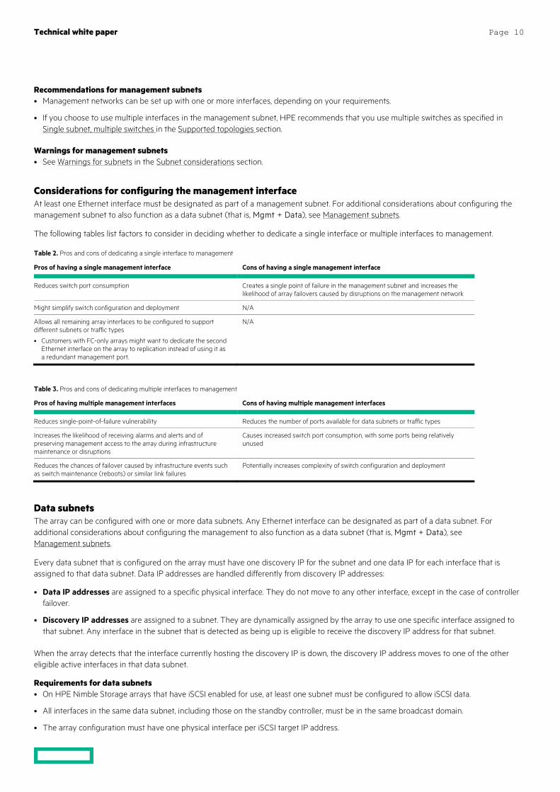
Considerations for configuring the management interface At least one Ethernet interface must be designated as part of a management subnet. For additional considerations about configuring the management subnet to also function as a data subnet (that is, Mgmt + Data), see Management subnets.
The following tables list factors to consider in deciding whether to dedicate a single interface or multiple interfaces to management.
Table 2. Pros and cons of dedicating a single interface to management
Pros of having a single management interface Cons of having a single management interface
Reduces switch port consumption Creates a single point of failure in the management subnet and increases the likelihood of array failovers caused by disruptions on the management network
Might simplify switch configuration and deployment N/A
Allows all remaining array interfaces to be configured to support different subnets or traffic types
• Customers with FC-only arrays might want to dedicate the second Ethernet interface on the array to replication instead of using it as a redundant management port.
N/A
Table 3. Pros and cons of dedicating multiple interfaces to management
Pros of having multiple management interfaces Cons of having multiple management interfaces
Reduces single-point-of-failure vulnerability Reduces the number of ports available for data subnets or traffic types
Increases the likelihood of receiving alarms and alerts and of preserving management access to the array during infrastructure maintenance or disruptions
Causes increased switch port consumption, with some ports being relatively unused
Reduces the chances of failover caused by infrastructure events such as switch maintenance (reboots) or similar link failures
Potentially increases complexity of switch configuration and deployment
Data subnets The array can be configured with one or more data subnets. Any Ethernet interface can be designated as part of a data subnet. For additional considerations about configuring the management to also function as a data subnet (that is, Mgmt + Data), see Management subnets.
Every data subnet that is configured on the array must have one discovery IP for the subnet and one data IP for each interface that is assigned to that data subnet. Data IP addresses are handled differently from discovery IP addresses:
• Data IP addresses are assigned to a specific physical interface. They do not move to any other interface, except in the case of controller failover.
• Discovery IP addresses are assigned to a subnet. They are dynamically assigned by the array to use one specific interface assigned to that subnet. Any interface in the subnet that is detected as being up is eligible to receive the discovery IP address for that subnet.
When the array detects that the interface currently hosting the discovery IP is down, the discovery IP address moves to one of the other eligible active interfaces in that data subnet.
Requirements for data subnets • On HPE Nimble Storage arrays that have iSCSI enabled for use, at least one subnet must be configured to allow iSCSI data.
• All interfaces in the same data subnet, including those on the standby controller, must be in the same broadcast domain.
• The array configuration must have one physical interface per iSCSI target IP address.
Technical white paper Page 11
Recommendations for data subnets • Whenever possible, provide dedicated data networks that are separate from the management network.
– The separation reduces traffic contention and makes it easier to prevent unauthorized access to iSCSI target IP addresses.
Warnings for data subnets • See Warnings for subnets in the Subnet considerations section.
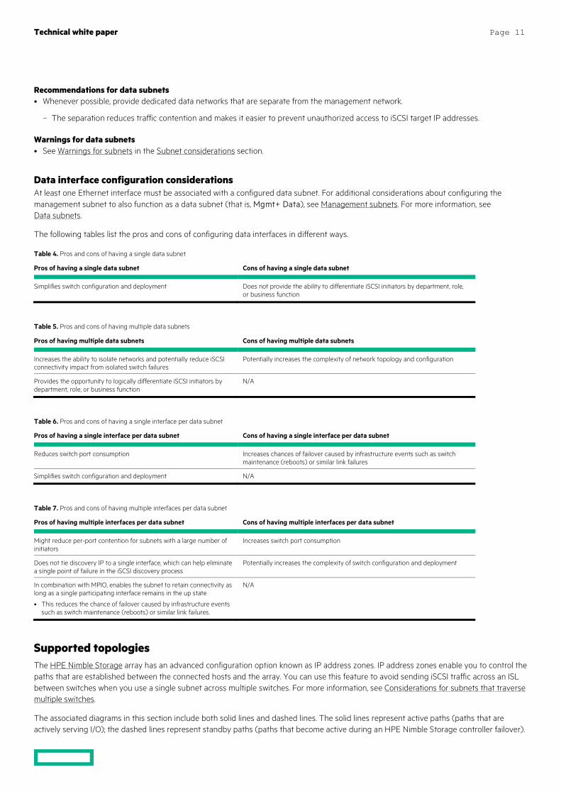
Data interface configuration considerations At least one Ethernet interface must be associated with a configured data subnet. For additional considerations about configuring the management subnet to also function as a data subnet (that is, Mgmt+ Data), see Management subnets. For more information, see Data subnets.
The following tables list the pros and cons of configuring data interfaces in different ways.
Table 4. Pros and cons of having a single data subnet
Pros of having a single data subnet Cons of having a single data subnet
Simplifies switch configuration and deployment Does not provide the ability to differentiate iSCSI initiators by department, role, or business function
Table 5. Pros and cons of having multiple data subnets
Pros of having multiple data subnets Cons of having multiple data subnets
Increases the ability to isolate networks and potentially reduce iSCSI connectivity impact from isolated switch failures
Potentially increases the complexity of network topology and configuration
Provides the opportunity to logically differentiate iSCSI initiators by department, role, or business function
N/A
Table 6. Pros and cons of having a single interface per data subnet
Pros of having a single interface per data subnet Cons of having a single interface per data subnet
Reduces switch port consumption Increases chances of failover caused by infrastructure events such as switch maintenance (reboots) or similar link failures
Simplifies switch configuration and deployment N/A
Table 7. Pros and cons of having multiple interfaces per data subnet
Pros of having multiple interfaces per data subnet Cons of having multiple interfaces per data subnet
Might reduce per-port contention for subnets with a large number of initiators
Increases switch port consumption
Does not tie discovery IP to a single interface, which can help eliminate a single point of failure in the iSCSI discovery process
Potentially increases the complexity of switch configuration and deployment
In combination with MPIO, enables the subnet to retain connectivity as long as a single participating interface remains in the up state
• This reduces the chance of failover caused by infrastructure events such as switch maintenance (reboots) or similar link failures.
N/A
Supported topologies The HPE Nimble Storage array has an advanced configuration option known as IP address zones. IP address zones enable you to control the paths that are established between the connected hosts and the array. You can use this feature to avoid sending iSCSI traffic across an ISL between switches when you use a single subnet across multiple switches. For more information, see Considerations for subnets that traverse multiple switches.
The associated diagrams in this section include both solid lines and dashed lines. The solid lines represent active paths (paths that are actively serving I/O); the dashed lines represent standby paths (paths that become active during an HPE Nimble Storage controller failover).
Technical white paper Page 12
Each of the described supported topologies must adhere to each of the requirements listed in this section. The following topologies are supported:
• Single subnet, single switch
• Single subnet, multiple switches
• Multiple subnets, single switch
• Multiple subnets, multiple connected switches
Note The terminology of individual manufacturers varies. This guide uses the terms stacked and ISL, as indicated in the glossary.
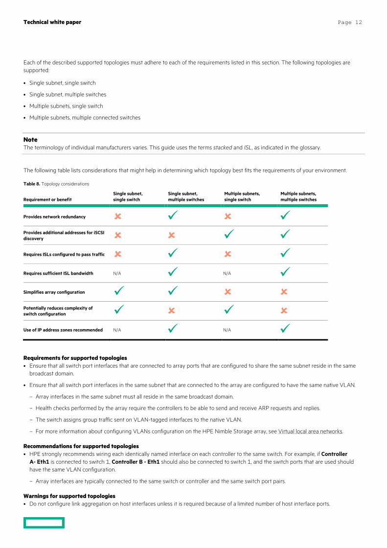
The following table lists considerations that might help in determining which topology best fits the requirements of your environment.
Table 8. Topology considerations
Requirement or benefit
Single subnet, single switch
Single subnet, multiple switches
Multiple subnets, single switch
Multiple subnets, multiple switches
Provides network redundancy Provides additional addresses for iSCSI discovery Requires ISLs configured to pass traffic Requires sufficient ISL bandwidth N/A N/A Simplifies array configuration Potentially reduces complexity of switch configuration Use of IP address zones recommended N/A N/A
Requirements for supported topologies • Ensure that all switch port interfaces that are connected to array ports that are configured to share the same subnet reside in the same
broadcast domain.
• Ensure that all switch port interfaces in the same subnet that are connected to the array are configured to have the same native VLAN.
– Array interfaces in the same subnet must all reside in the same broadcast domain.
– Health checks performed by the array require the controllers to be able to send and receive ARP requests and replies.
– The switch assigns group traffic sent on VLAN-tagged interfaces to the native VLAN.
– For more information about configuring VLANs configuration on the HPE Nimble Storage array, see Virtual local area networks.
Recommendations for supported topologies • HPE strongly recommends wiring each identically named interface on each controller to the same switch. For example, if Controller
A- Eth1 is connected to switch 1, Controller B - Eth1 should also be connected to switch 1, and the switch ports that are used should have the same VLAN configuration.
– Array interfaces are typically connected to the same switch or controller and the same switch port pairs.
Warnings for supported topologies • Do not configure link aggregation on host interfaces unless it is required because of a limited number of host interface ports.
Technical white paper Page 13
• Do not configure link aggregation on interfaces that are connected to the array.
– Link aggregation (for example, Cisco EtherChannel) is not supported for array-facing switch ports or interfaces.
• Do not enable ARP filtering features on the interfaces that are connected to the array. Enabling them might inhibit health checks and other functionality that the array uses during normal operation.
– For more information, see Requirements for supported topologies.
Direct connect Direct connect configurations are supported only for Fibre Channel connections. Review the Validated Configuration Matrix on the HPE InfoSight web portal to determine the requirements for a direct-connect Fibre Channel configuration.
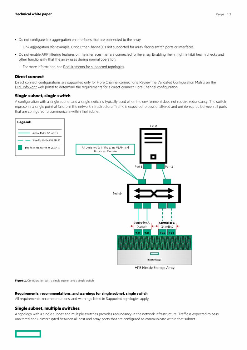
Single subnet, single switch A configuration with a single subnet and a single switch is typically used when the environment does not require redundancy. The switch represents a single point of failure in the network infrastructure. Traffic is expected to pass unaltered and uninterrupted between all ports that are configured to communicate within that subnet.
Figure 1. Configuration with a single subnet and a single switch
Requirements, recommendations, and warnings for single subnet, single switch All requirements, recommendations, and warnings listed in Supported topologies apply.
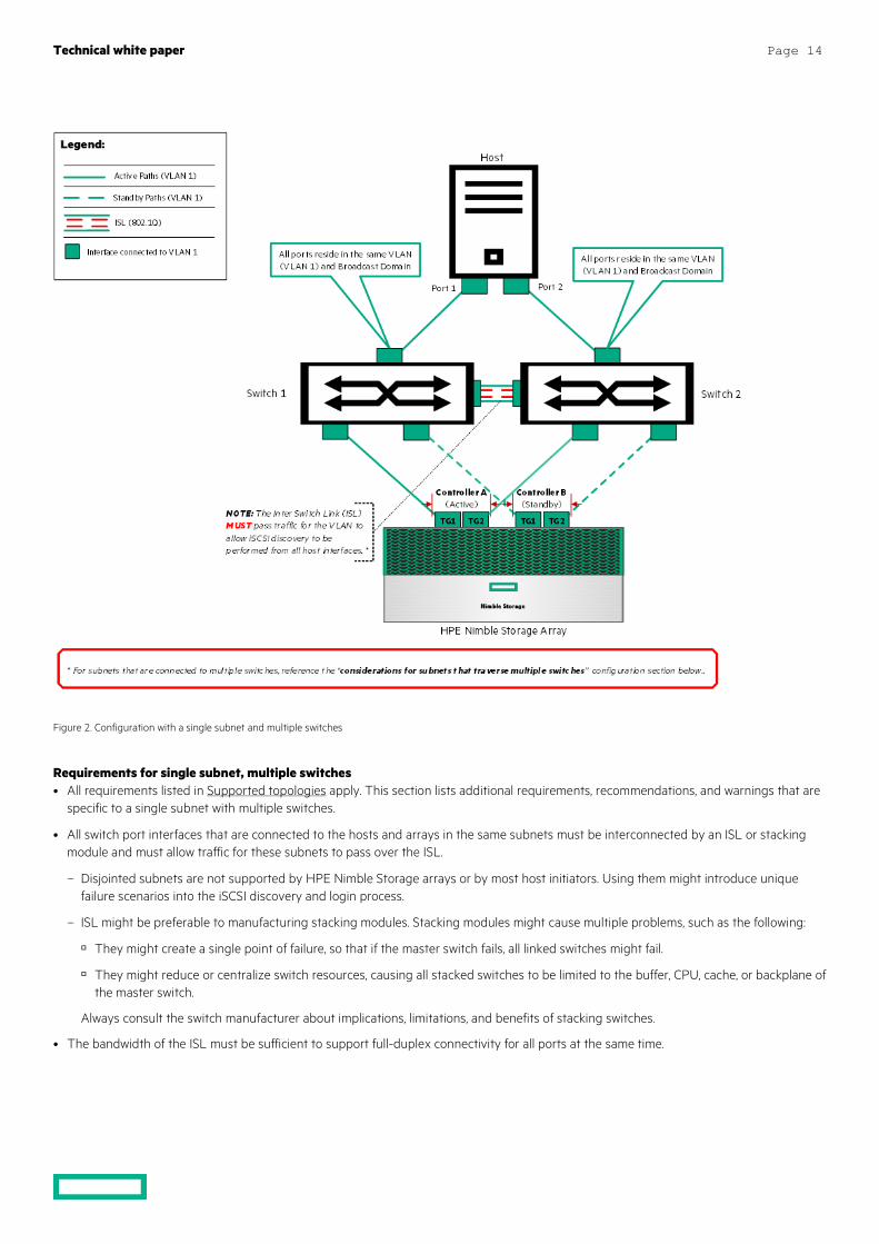
Single subnet, multiple switches A topology with a single subnet and multiple switches provides redundancy in the network infrastructure. Traffic is expected to pass unaltered and uninterrupted between all host and array ports that are configured to communicate within that subnet.
Technical white paper Page 14
Figure 2. Configuration with a single subnet and multiple switches
Requirements for single subnet, multiple switches • All requirements listed in Supported topologies apply. This section lists additional requirements, recommendations, and warnings that are
specific to a single subnet with multiple switches.
• All switch port interfaces that are connected to the hosts and arrays in the same subnets must be interconnected by an ISL or stacking module and must allow traffic for these subnets to pass over the ISL.
– Disjointed subnets are not supported by HPE Nimble Storage arrays or by most host initiators. Using them might introduce unique failure scenarios into the iSCSI discovery and login process.
– ISL might be preferable to manufacturing stacking modules. Stacking modules might cause multiple problems, such as the following:
They might create a single point of failure, so that if the master switch fails, all linked switches might fail.
They might reduce or centralize switch resources, causing all stacked switches to be limited to the buffer, CPU, cache, or backplane of the master switch.
Always consult the switch manufacturer about implications, limitations, and benefits of stacking switches.
• The bandwidth of the ISL must be sufficient to support full-duplex connectivity for all ports at the same time.
Technical white paper Page 15
Recommendations for single subnet, multiple switches • Use the IP address zone feature to eliminate or reduce ISL cross-traffic. See Considerations for subnets that traverse multiple switches.
• Separate the connections from the active and the standby controllers in a manner that connects each controller to multiple switch modules (or to multiple blades if there are multiple blades in the chassis).
– If possible, you should understand switch architecture well enough to be able to identify the application-specific integrated circuits (ASICs) and field-programmable gate arrays (FPGAs) on the network device to determine whether there is single point of failure in the network switch.
Warnings for single subnet, multiple switches • Do not enable ARP filtering features on the interfaces connected to the array. For more information, see Requirements for supported
topologies.
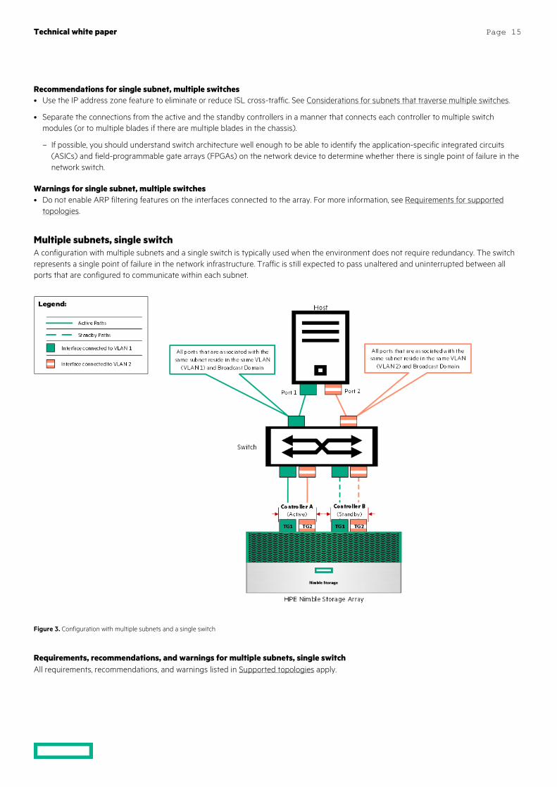
Multiple subnets, single switch A configuration with multiple subnets and a single switch is typically used when the environment does not require redundancy. The switch represents a single point of failure in the network infrastructure. Traffic is still expected to pass unaltered and uninterrupted between all ports that are configured to communicate within each subnet.
Figure 3. Configuration with multiple subnets and a single switch
Requirements, recommendations, and warnings for multiple subnets, single switch All requirements, recommendations, and warnings listed in Supported topologies apply.
Technical white paper Page 16
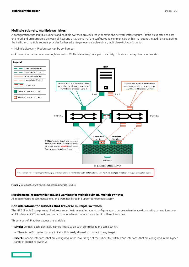
Multiple subnets, multiple switches A configuration with multiple subnets and multiple switches provides redundancy in the network infrastructure. Traffic is expected to pass unaltered and uninterrupted between all host and array ports that are configured to communicate within that subnet. In addition, separating the traffic into multiple subnets provides further advantages over a single-subnet, multiple-switch configuration:
• Multiple discovery IP addresses can be configured.
• A disruption that occurs on a single subnet or VLAN is less likely to impair the ability of hosts and arrays to communicate.
Figure 4. Configuration with multiple subnets and multiple switches
Requirements, recommendations, and warnings for multiple subnets, multiple switches All requirements, recommendations, and warnings listed in Supported topologies apply.
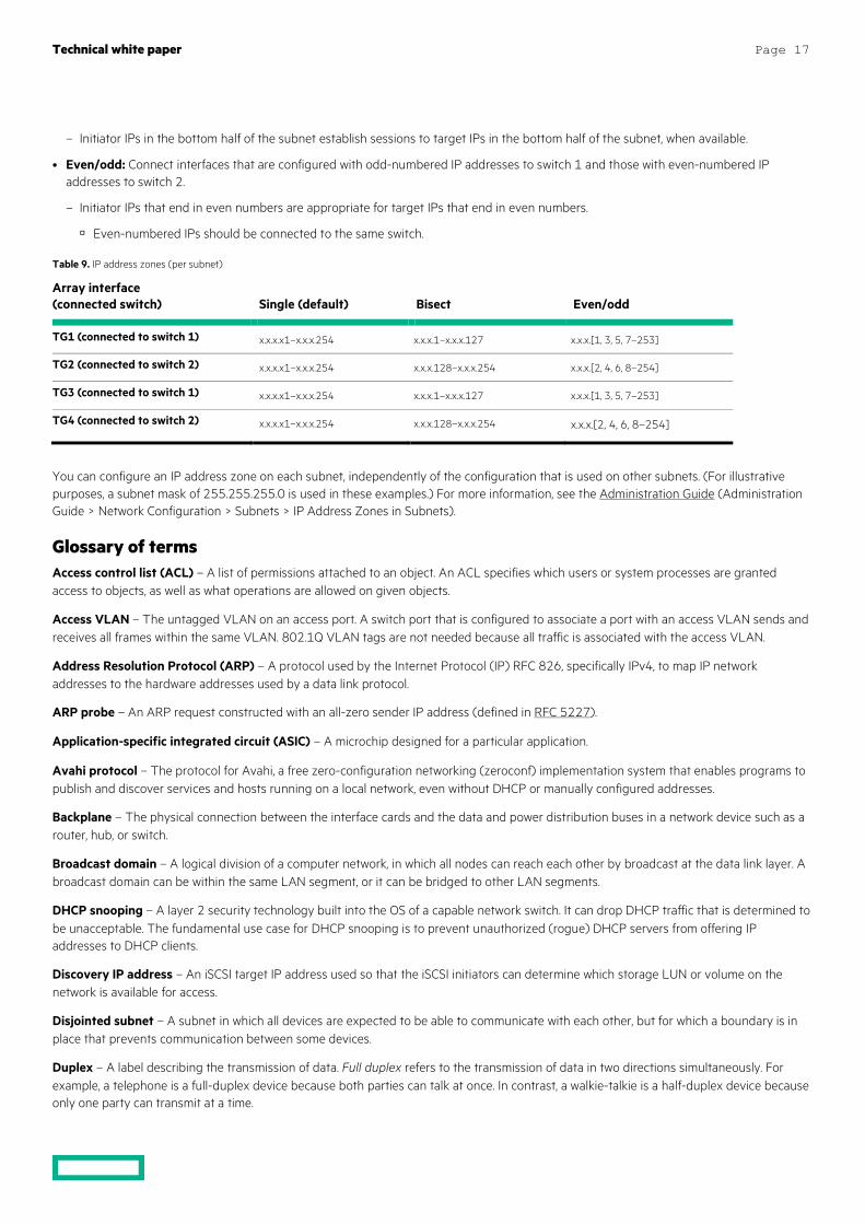
Considerations for subnets that traverse multiple switches The HPE Nimble Storage array IP address zones feature enables you to configure your storage system to avoid balancing connections over an ISL when an iSCSI subnet has two or more interfaces that are connected to different switches.
Three types of IP address zones are available:
• Single: Connect each identically named interface on each controller to the same switch.
– There is no ISL protection; any initiator IP is freely allowed to connect to any target.
• Bisect: Connect interfaces that are configured in the lower range of the subnet to switch 1 and interfaces that are configured in the higher range of subnet to switch 2.
Technical white paper Page 17
– Initiator IPs in the bottom half of the subnet establish sessions to target IPs in the bottom half of the subnet, when available.
• Even/odd: Connect interfaces that are configured with odd-numbered IP addresses to switch 1 and those with even-numbered IP addresses to switch 2.
– Initiator IPs that end in even numbers are appropriate for target IPs that end in even numbers.
Even-numbered IPs should be connected to the same switch.
Table 9. IP address zones (per subnet)
Array interface (connected switch)
Single (default)
Bisect
Even/odd
TG1 (connected to switch 1) x.x.x.x1–x.x.x.254 x.x.x.1–x.x.x.127 x.x.x.[1, 3, 5, 7–253]
TG2 (connected to switch 2) x.x.x.x1–x.x.x.254 x.x.x.128–x.x.x.254 x.x.x.[2, 4, 6, 8–254]
TG3 (connected to switch 1) x.x.x.x1–x.x.x.254 x.x.x.1–x.x.x.127 x.x.x.[1, 3, 5, 7–253]
TG4 (connected to switch 2) x.x.x.x1–x.x.x.254 x.x.x.128–x.x.x.254 x.x.x.[2, 4, 6, 8–254]
You can configure an IP address zone on each subnet, independently of the configuration that is used on other subnets. (For illustrative purposes, a subnet mask of 255.255.255.0 is used in these examples.) For more information, see the Administration Guide (Administration Guide > Network Configuration > Subnets > IP Address Zones in Subnets).
Glossary of terms Access control list (ACL) – A list of permissions attached to an object. An ACL specifies which users or system processes are granted access to objects, as well as what operations are allowed on given objects.
Access VLAN – The untagged VLAN on an access port. A switch port that is configured to associate a port with an access VLAN sends and receives all frames within the same VLAN. 802.1Q VLAN tags are not needed because all traffic is associated with the access VLAN.
Address Resolution Protocol (ARP) – A protocol used by the Internet Protocol (IP) RFC 826, specifically IPv4, to map IP network addresses to the hardware addresses used by a data link protocol.
ARP probe – An ARP request constructed with an all-zero sender IP address (defined in RFC 5227).
Application-specific integrated circuit (ASIC) – A microchip designed for a particular application.
Avahi protocol – The protocol for Avahi, a free zero-configuration networking (zeroconf) implementation system that enables programs to publish and discover services and hosts running on a local network, even without DHCP or manually configured addresses.
Backplane – The physical connection between the interface cards and the data and power distribution buses in a network device such as a router, hub, or switch.
Broadcast domain – A logical division of a computer network, in which all nodes can reach each other by broadcast at the data link layer. A broadcast domain can be within the same LAN segment, or it can be bridged to other LAN segments.
DHCP snooping – A layer 2 security technology built into the OS of a capable network switch. It can drop DHCP traffic that is determined to be unacceptable. The fundamental use case for DHCP snooping is to prevent unauthorized (rogue) DHCP servers from offering IP addresses to DHCP clients.
Discovery IP address – An iSCSI target IP address used so that the iSCSI initiators can determine which storage LUN or volume on the network is available for access.
Disjointed subnet – A subnet in which all devices are expected to be able to communicate with each other, but for which a boundary is in place that prevents communication between some devices.
Duplex – A label describing the transmission of data. Full duplex refers to the transmission of data in two directions simultaneously. For example, a telephone is a full-duplex device because both parties can talk at once. In contrast, a walkie-talkie is a half-duplex device because only one party can transmit at a time.
Technical white paper Page 18
Ethernet VPN (EVPN) – A VPN between Ethernet devices (for example, MAC addresses), as opposed to a VPN between IP addresses. EVPN enables controlled communication between Ethernet end points, regardless of IP addresses, and can be used over WAN circuits or between individual ports in an Ethernet switch. When used in conjunction with VXLAN in an Ethernet network, EVPN is one method of creating a software-defined network.
Frame check sequence (FCS) headers – The extra bits and characters added to data packets for error detection and control. Each frame is comprised of bits of data appended to the header, which holds basic information such as source and destination MAC addresses and application and contains the cyclic redundancy check (CRC).
Flow control – A mechanism for temporarily pausing the transmission of data on Ethernet networks when a sending node transmits data faster than the receiving node can accept it.
Field-Programmable Gate Array (FPGA) – An integrated circuit (IC) that can be programmed in the field after manufacture. Manufacturers use FPGAs in the design of specialized ICs that can later be produced hard-wired in large quantities for distribution to computer manufacturers and end users.
Gratuitous ARP – An ARP response that was not prompted by an ARP request. A gratuitous ARP is sent as a broadcast frame, as a way for a node to announce or update its IP-to-MAC mapping to the entire network.
Ifaces (Linux) – Linux interfaces that are used for iSCSI port binding. Creating ifaces in Linux for iSCSI interfaces enables full-mesh connectivity from the host to the array when a single subnet is used across multiple interfaces.
Initiator – Software or hardware that enables a host computer to send data to an external iSCSI-based storage array through an Ethernet network.
Interface – The point of interconnection between a computer and a private or public network. A network interface is generally a network interface card (NIC), but it does not have to have a physical form.
IP address zones (or network affinity zones – NAZs) – A feature that makes it possible to configure the storage system to avoid balancing connections over an ISL when an iSCSI subnet has two or more interfaces that are connected to different switches.
Internet Small Computer System Interface (iSCSI) – An IP-based storage-networking standard that enables SCSI commands to be sent end-to-end over LANs, WANs, or the internet.
Inter-switch link (ISL) – A connection that joins two switches and maintains VLAN information as traffic flows between switches and routers. The term ISL may refer to the proprietary Cisco Inter-Switch Link standard or to the general concept of connecting nonstacked switches through one or more Ethernet cables.
Jumbo frames – An Ethernet frame with a payload greater than the standard MTU of 1,500 bytes. Jumbo frames can be as large as 9000 bytes.
Local area network (LAN) – A computer network that spans a relatively small area.
Latency – Any of several kinds of delays typically incurred in the processing of network data. A low-latency network connection is one that experiences short delay times, whereas a high-latency connection is affected by long delays.
Link aggregation – A way of bundling many individual Ethernet links together so that they act like a single logical link.
Link aggregation group (LAG) – A collection of Ethernet links that participate in link aggregation with each other.
Lossy network – A network that is likely to experience packet loss.
Least queue depth (LQD) – An MPIO load-balancing policy that can help determine which path will be used for the next I/O operation, based on which path is least utilized at that moment.
Media access control (MAC) address – A unique identifier of a device. The MAC address is assigned to a network interface controller (NIC) for communications at the data link layer of a network segment. MAC addresses are used as a network address for most IEEE 802 network technologies, including Ethernet, Wi-Fi, and Bluetooth®.
Multipath I/O (MPIO) – A framework designed to mitigate the effects of adapter failure by providing an alternative data path between storage devices and hosts.
Maximum transmission unit (MTU) – The largest size frame, specified in octets (eight-bit bytes), that can be sent in any Ethernet-based network. Network devices use the configured MTU setting to determine the maximum size of each frame in any transmission.
Technical white paper Page 19
Native VLAN – The VLAN ID to which untagged packets are assigned.
Nonblocking switch - A switch that has a backplane that provides enough bandwidth to support full-duplex connectivity for all ports at the same time.
Packet loss – The failure of one or more transmitted packets to arrive at their destination.
Packet storm – The severe congestion that occurs when a network system is overwhelmed by continuous multicast or broadcast traffic.
Proxy ARP – The technique by which one host, usually a router or switch, answers ARP requests that were intended for another machine.
Quality of service (QoS) – Any technology that manages data traffic to reduce packet loss, latency, and jitter on the network. QoS controls and manages network resources by setting priorities for specific types of data on the network.
Round robin (RR) – An MPIO load-balancing policy that helps determine which path will be used for the next I/O operation. RR assigns the I/O to the next path, regardless of its level of use.
Spanning Tree Protocol (STP) – A network protocol that builds a loop-free logical topology for Ethernet networks to prevent packet storms.
Stack/stacked switches/multiswitch stack – A set of switches or switch modules that are connected through dedicated stacking ports or ports that are defined in the software to be stacking ports. Stacked switches typically behave as if they were one physical switch.
Storm control/unicast storm control – A safety measure on switches that can block or discard traffic when it occurs at a rate higher than a configured threshold.
Subnet – A logical partition of an IP network into multiple smaller network segments. It is typically used to subdivide large networks into smaller, more efficient subnetworks. Each subnet allows its connected devices to communicate with each other, and routers are used to communicate between subnets.
Target – An iSCSI storage device that is capable of providing shared block storage to clients across a TCP/IP network.
Transmission Control Protocol (TCP) congestion control – A TCP algorithm that seeks to control throughput to minimize packet loss in a TCP conversation.
TCP global synchronization – The situation in which one host can introduce traffic patterns that cause the other hosts to behave similarly. TCP global synchronization is usually associated with switch congestion, packet loss, loss recovery, and TCP congestion control.
Throughput – The amount of data that is moved successfully from one place to another in a network within a given time period. Throughput is typically measured in bits per second (bps), as in megabits per second (Mbps) or gigabits per second (Gbps).
Unicast – Communication between a single sender and a single receiver over a network.
Virtual Extensible LAN (VXLAN) – An evolution of traditional VLANs. VXLANs can support more VLAN IDs (16 million versus 4096). They also enable the creation of VLANs that can be as small as a single switch port. When combined with eVPN to allow layer 3 routing between VXLANs, technologies such as software-defined networking (SDN) can dynamically redesign broadcast domains without fundamentally changing the switch port configuration. In this technique, layer 3 (IP-routed) traffic is passed between VXLANS over eVPN instances, and the eVPN instances can be dynamically managed based on rules that are defined in the network infrastructure.
Virtual local area network (VLAN) – A custom network that is used to segment broadcast domains.
VLAN tagging – A method used by networked devices to identify which VLAN each individual packet should be associated with.
Wide area network (WAN) – A geographically distributed private telecommunications network that interconnects multiple LANs. In an enterprise, a WAN might consist of connections to a company’s headquarters, branch offices, colocation facilities, cloud services, and other facilities.
Wirespeed – The hypothetical peak physical layer net bitrate (useful information rate) of a cable (consisting of fiber-optical wires or copper wires) combined with a particular digital communication device, interface, or port.
Zero-configuration networking (zeroconf) – A set of technologies that automatically creates a usable computer network, based on the Internet Protocol Suite (TCP/IP), in the absence of DHCP or manual configuration.
Technical white paper
Share now
Get updates
© Copyright 2019 Hewlett Packard Enterprise Development LP. The information contained herein is subject to change without notice. The only warranties for Hewlett Packard Enterprise products and services are set forth in the express warranty statements accompanying such products and services. Nothing herein should be construed as constituting an additional warranty. Hewlett Packard Enterprise shall not be liable for technical or editorial errors or omissions contained herein.
Windows is either a registered trademark or trademark of Microsoft Corporation in the United States and/or other countries. Linux is the registered trademark of Linus Torvalds in the U.S. and other countries. VMware and VMware vSphere are registered trademarks or trademarks of VMware, Inc. in the United States and/or other jurisdictions. Bluetooth is a trademark owned by its proprietor and used by Hewlett Packard Enterprise under license. All other third-party marks are property of their respective owners.
a00069468ENW, April 2019
Resources Administration Guide infosight.hpe.com/org/urn%3Animble%3A0013400001QfUyiAAF/resources/nimble/docs?Document+Type=Administration+Guide
CLI Administration Guide infosight.hpe.com/org/urn%3Animble%3A0013400001QfUyiAAF/resources/nimble/docs?Document+Type=Administration+Guide
GUI Administration Guide infosight.hpe.com/org/urn%3Animble%3A0013400001QfUyiAAF/resources/nimble/docs?Document+Type=Administration+Guide
Linux Integration Guide infosight.hpe.com/org/urn%3Animble%3A0013400001QfUyiAAF/resources/nimble/docs?term=linux
VMware Integration Guide infosight.hpe.com/org/urn%3Animble%3A0013400001QfUyiAAF/resources/nimble/docs?term=vmware
Windows Integration Guide infosight.hpe.com/org/urn%3Animble%3A0013400001QfUyiAAF/resources/nimble/docs?Document+Type=Integration+Guide&Nimble+Software+and+Solutions=Windows+Toolkit+%28NWT%29
Learn more at hpe.com/storage