hpe proliant dl380 gen10 server maintenance and service · pdf filehpe proliant dl380 gen10...
TRANSCRIPT

HPE ProLiant DL380 Gen10 ServerMaintenance and Service Guide
Part Number: 868989-001Published: July 2017Edition: 1
AbstractThis document is for the person who installs, administers, and troubleshoots servers and storagesystems. Hewlett Packard Enterprise assumes you are qualified in the servicing of computerequipment and trained in recognizing hazards in products with hazardous energy levels.

NoticesThe information contained herein is subject to change without notice. The only warranties for Hewlett PackardEnterprise products and services are set forth in the express warranty statements accompanying suchproducts and services. Nothing herein should be construed as constituting an additional warranty. HewlettPackard Enterprise shall not be liable for technical or editorial errors or omissions contained herein.
Confidential computer software. Valid license from Hewlett Packard Enterprise required for possession, use,or copying. Consistent with FAR 12.211 and 12.212, Commercial Computer Software, Computer SoftwareDocumentation, and Technical Data for Commercial Items are licensed to the U.S. Government undervendor's standard commercial license.
Links to third-party websites take you outside the Hewlett Packard Enterprise website. Hewlett PackardEnterprise has no control over and is not responsible for information outside the Hewlett Packard Enterprisewebsite.
AcknowledgmentsIntel® and Xeon® are trademarks of Intel Corporation in the United States and other countries.
Microsoft® and Windows® are either registered trademarks or trademarks of Microsoft Corporation in theUnited States and/or other countries.

Contents
Illustrated parts catalog.............................................................................. 7Mechanical components......................................................................................................................7
Air baffle spare part.................................................................................................................. 8Access panel spare parts......................................................................................................... 8Tertiary PCI riser cage spare part.............................................................................................8Primary and secondary PCI riser cage spare part....................................................................8Chassis ears spare parts..........................................................................................................8Fan cage spare part..................................................................................................................92U bezel spare part.................................................................................................................. 9Rail kit spare parts....................................................................................................................9Miscellaneous blanks kits spare parts...................................................................................... 9
System components..........................................................................................................................10DIMM spare parts................................................................................................................... 12Processor spare parts.............................................................................................................12Heatsink spare parts...............................................................................................................14Power supply spare parts....................................................................................................... 14Controller spare parts............................................................................................................. 14PCI riser board spare parts.....................................................................................................15FlexibleLOM adapter spare parts........................................................................................... 16System board spare part........................................................................................................ 16System battery spare part.......................................................................................................16
Server options................................................................................................................................... 16Drive spare parts.................................................................................................................... 18Fan spare parts.......................................................................................................................21Backplane board spare parts..................................................................................................22Chassis Intrusion Detection Switch spare part....................................................................... 22GPU options spare parts........................................................................................................ 22Rear serial port interface spare part....................................................................................... 22HPE 12Gb DL380 Gen10 SAS Expander Card spare part.....................................................23HPE Smart Storage Battery spare parts.................................................................................23Power module spare parts......................................................................................................23LFF I/O UID spare parts......................................................................................................... 23HPE Trusted Platform Module 2.0 spare part.........................................................................23Cable spare parts................................................................................................................... 23Thermal grease spare parts....................................................................................................24
Customer self repair..................................................................................25
Removal and replacement procedures....................................................35Required tools................................................................................................................................... 35Safety considerations........................................................................................................................ 35
Preventing electrostatic discharge..........................................................................................35Symbols on equipment........................................................................................................... 35Server warnings and cautions................................................................................................ 36
Preparation procedures.....................................................................................................................36Power down the server ..........................................................................................................36Extend the server from the rack..............................................................................................37Remove the server from the rack........................................................................................... 37
Contents 3

Access the product rear panel................................................................................................38Accessing the Systems Insight Display.................................................................................. 38Remove the access panel...................................................................................................... 39Release the full-length expansion board retainer................................................................... 39
Removing and replacing a drive blank.............................................................................................. 40Removing and replacing drives......................................................................................................... 40
Removing and replacing a hot-plug drive............................................................................... 40Removing and replacing an NVMe drive................................................................................ 41Removing and replacing an M.2 SSD.....................................................................................41
Removing and replacing the hot-plug fan..........................................................................................42Removing and replacing a power supply blank.................................................................................43Removing and replacing the AC power supply..................................................................................43Removing the air baffle......................................................................................................................44Removing and replacing the primary or secondary PCIe riser cages............................................... 45Removing and replacing the tertiary PCIe riser cage........................................................................46Removing and replacing the PCIe riser blank................................................................................... 47Removing and replacing the PCIe riser board...................................................................................48Removing and replacing an expansion slot blank............................................................................. 50Removing and replacing an expansion board................................................................................... 51Removing and replacing the fan cage...............................................................................................52Removing and replacing the FlexibleLOM.........................................................................................53Removing and replacing the small form factor universal media bay................................................. 53Removing and replacing the LFF power switch module....................................................................54Removing and replacing the SFF optical drive..................................................................................55Removing and replacing the LFF optical drive.................................................................................. 57Removing and replacing the 8-SFF drive cage................................................................................. 58Removing and replacing the 8-SFF drive backplane.........................................................................59Removing and replacing the 2-SFF front drive cage.........................................................................59Removing and replacing the 2-SFF rear drive bay and riser cage....................................................60Removing and replacing the 2-SFF drive cage................................................................................. 61Removing and replacing the 2-SFF rear drive backplane................................................................. 62Removing and replacing a 4 LFF midplane cage..............................................................................63Removing and replacing a three-bay LFF rear drive cage................................................................ 64Removing and replacing the LFF backplane assembly.....................................................................65Removing and replacing a front LFF drive backplane.......................................................................65Removing and replacing the 3-LFF rear drive backplane..................................................................66Removing and replacing a rear serial port interface (primary/secondary).........................................67Removing and replacing a rear serial port interface (tertiary riser)................................................... 68Removing and replacing an SFF power switch module.................................................................... 69Removing and replacing an LFF chassis ear with power/UID...........................................................70Removing and replacing an SFF standard chassis ear.....................................................................71Removing and replacing a GPU enablement board..........................................................................72Removing and replacing a DIMM...................................................................................................... 73Removing and replacing the HPE Smart Storage Battery.................................................................74Removing and replacing the HPE Flexible Smart Array Controller................................................... 75Removing and replacing the system battery..................................................................................... 76Removing and replacing the system board....................................................................................... 77
Re-entering the server serial number and product ID.............................................................80HPE Trusted Platform Module 2.0 Gen10 Option............................................................................. 80
Troubleshooting.........................................................................................81Troubleshooting resources................................................................................................................ 81
Diagnostic tools.........................................................................................82
4 Contents
Product QuickSpecs..........................................................................................................................82UEFI System Utilities.........................................................................................................................82
Selecting the boot mode ........................................................................................................82Secure Boot............................................................................................................................83Launching the Embedded UEFI Shell ....................................................................................83
Intelligent Provisioning.......................................................................................................................84Intelligent Provisioning operation............................................................................................84
HPE Insight Remote Support............................................................................................................ 84USB support...................................................................................................................................... 85
External USB functionality...................................................................................................... 85HPE Smart Storage Administrator.....................................................................................................85
Component identification......................................................................... 87Front panel components....................................................................................................................87Front panel LEDs and buttons...........................................................................................................89
UID button functionality...........................................................................................................93Power fault LEDs....................................................................................................................93Systems Insight Display LEDs................................................................................................93Systems Insight Display combined LED descriptions.............................................................94
Rear panel components.................................................................................................................... 96Rear panel LEDs............................................................................................................................... 97System board components................................................................................................................98
System maintenance switch descriptions...............................................................................99Processor, heatsink, and socket components................................................................................. 100Drives.............................................................................................................................................. 100
SAS/SATA drive components and LEDs...............................................................................101NVMe drive components and LEDs......................................................................................102uFF drive components and LEDs......................................................................................... 102
Fan bay numbering..........................................................................................................................103Drive box identification.................................................................................................................... 104Drive bay numbering....................................................................................................................... 105
Drive bay numbering: Smart Array controller........................................................................105Drive bay numbering: SAS expander................................................................................... 107Drive bay numbering: NVMe drives......................................................................................109uFF drive bay numbering...................................................................................................... 110
Cabling...................................................................................................... 111HPE ProLiant Gen10 DL Servers Storage Cabling Guidelines........................................................111Cabling diagrams............................................................................................................................. 111
Cable routing: Front 2SFF drive option for SFF....................................................................113Cable routing: Front 2SFF drive option for LFF.................................................................... 114Cable routing: Front 2SFF drive options (3 position cable)...................................................115Cable routing: Front 8SFF drive options............................................................................... 116Cable routing: Front 8SFF NVMe/SAS premium drive option...............................................118Cable routing: Front 8SFF NVMe drive options.................................................................... 118Cable routing: Front 2SFF NVMe drive option for SFF.........................................................120Cable routing: Front 2SFF NVMe drive option for LFF.........................................................121Cable routing: Midplane 4LFF drive option...........................................................................121Cable routing: Rear 3LFF drive option..................................................................................122Cable routing: Rear 2SFF drive options............................................................................... 122Cable routing: HPE 12G SAS Expander to a controller........................................................123Cable routing: Systems Insight Display................................................................................ 124
Contents 5

Specifications.......................................................................................... 125Environmental specifications...........................................................................................................125Mechanical specifications................................................................................................................125Power supply specifications............................................................................................................ 126
HPE 500W Flex Slot Platinum Hot-plug Power Supply........................................................ 126HPE 800W Flex Slot Platinum Hot-plug Power Supply........................................................ 127HPE 800W Flex Slot Titanium Plus Hot-plug Power Supply................................................ 128HPE 800W Flex Slot Universal Hot-plug Power Supply....................................................... 129HPE 800W Flex Slot -48VDC Hot-plug Power Supply......................................................... 130HPE 1600W Flex Slot Platinum Hot Plug Power Supply......................................................131
Acronyms and abbreviations................................................................. 132
Documentation feedback........................................................................ 134
6 Contents

Illustrated parts catalogMechanical components
Hewlett Packard Enterprise continually improves and changes product parts. For complete and currentsupported parts information, see the Hewlett Packard Enterprise PartSurfer website.
Item Description
1 Air baffle spare part on page 8
2 Access panel spare parts on page 8
3 Tertiary PCI riser cage spare part on page 8
4 Primary and secondary PCI riser cage spare parton page 8
5 Chassis ears spare parts on page 8
6 Fan cage spare part on page 9
7 2U bezel spare part on page 9*
8 Rail kit spare parts on page 9*
9 Miscellaneous blanks kits spare parts on page9*
• Front miscellaneous blanks kit spare parts onpage 9
• Rear miscellaneous blanks kit spare parts onpage 9
Table Continued
Illustrated parts catalog 7

Item Description
• Rear 2 SFF/miscellaneous blanks and bracketkit spare parts on page 10
• Fan blank, Smart Storage Battery latch, andPCIe retainer kit spare parts on page 10
• Optical drive blank spare part on page 10
* Not shown
For more information, see Removal and replacement procedures on page 35.
Air baffle spare partCustomer self repair on page 25: mandatory
Description Spare part number
Air baffle 875054-001
Access panel spare partsCustomer self repair on page 25: mandatory
Description Spare part number
Access panel (SFF model) 875052-001
Access panel (LFF model) 875053-001
Tertiary PCI riser cage spare partCustomer self repair on page 25: optional
Description Spare part number
Tertiary PCI riser cage 875057-001
Primary and secondary PCI riser cage spare partCustomer self repair on page 25: mandatory
Description Spare part number
Primary and secondary PCI riser cage 875056-001
Chassis ears spare partsCustomer self repair on page 25: mandatory
8 Air baffle spare part

Description Spare part number
SFF standard left and right chassis ears kit 875083-001
LFF power/UID left and right chassis ears kit 875084-001
Fan cage spare partCustomer self repair on page 25: mandatory
Description Spare part number
Fan cage 875055-001
2U bezel spare partCustomer self repair on page 25: mandatory
Description Spare part number
2U bezel 875065-001
Rail kit spare partsCustomer self repair on page 25: mandatory
Description Spare part number
SFF 2U easy install rail kit 744114-001
LFF 2U easy install rail kit 744115-001
2U cable management arm 744116-001
Miscellaneous blanks kits spare parts
Front miscellaneous blanks kit spare partsCustomer self repair on page 25: mandatory
Description Spare part number
Front miscellaneous blanks kit 875069-001
2 SFF Flex Bay hard drive blank —
Hard drive box, standard blank —
Hard drive box blank, NVMe —
LFF hard drive box blank —
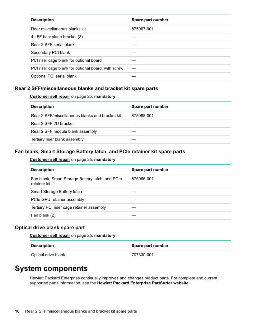
Rear miscellaneous blanks kit spare partsCustomer self repair on page 25: mandatory
Fan cage spare part 9
Description Spare part number
Rear miscellaneous blanks kit 875067-001
4 LFF backplane bracket (3) —
Rear 2 SFF serial blank —
Secondary PCI blank —
PCI riser cage blank for optional board —
PCI riser cage blank for optional board, with screw —
Optional PCI serial blank —
Rear 2 SFF/miscellaneous blanks and bracket kit spare partsCustomer self repair on page 25: mandatory
Description Spare part number
Rear 2 SFF/miscellaneous blanks and bracket kit 875068-001
Rear 2 SFF 2U bracket —
Rear 2 SFF module blank assembly —
Tertiary riser blank assembly —
Fan blank, Smart Storage Battery latch, and PCIe retainer kit spare partsCustomer self repair on page 25: mandatory
Description Spare part number
Fan blank, Smart Storage Battery latch, and PCIeretainer kit
875066-001
Smart Storage Battery latch —
PCIe GPU retainer assembly —
Tertiary PCI riser cage retainer assembly —
Fan blank (2) —
Optical drive blank spare partCustomer self repair on page 25: mandatory
Description Spare part number
Optical drive blank 707300-001
System componentsHewlett Packard Enterprise continually improves and changes product parts. For complete and currentsupported parts information, see the Hewlett Packard Enterprise PartSurfer website.
10 Rear 2 SFF/miscellaneous blanks and bracket kit spare parts

Item Description
1 DIMM spare parts on page 12
2 Processor spare parts on page 12
• 31XX processor spare parts on page 12
• 41XX processor spare parts on page 12
• 51XX processor spare parts on page 12
• 61xx processor spare parts on page 13
• 81xx processor spare parts on page 13
3 Heatsink spare parts on page 14
4 Power supply spare parts on page 14
5 Controller spare parts on page 14
• Smart Array controller spare parts on page14
• Host bus adapter spare parts on page 15
• Converged network adapter spare parts onpage 15
6 PCI riser board spare parts on page 15
7 FlexibleLOM adapter spare parts on page 16
8 System board spare part on page 16
9 System battery spare part on page 16*
Illustrated parts catalog 11

* Not shown
For more information, see Removal and replacement procedures on page 35.
DIMM spare partsCustomer self repair on page 25: mandatory
Description Spare part number
DIMM, 8GB PC4-2666V-R,1Gx8 850879-001
DIMM, 16GB PC4-2666V-R,2Rx4 850880-001
DIMM, 16GB PC4-2666V-R,1Rx8 868846-001
DIMM, 32GB PC4-2666V-R,2Gx4 850881-001
DIMM, 64GB PC4-2666V-L,2Gx4 850882-001
Processor spare parts
31XX processor spare partsCustomer self repair on page 25: no
Description Spare part number
1.75-GHz Intel Xeon-B 3104 processor 875709-001
1.75-GHz Intel Xeon-B 3106 processor 875710-001
41XX processor spare partsCustomer self repair on page 25: no
Description Spare part number
1.8-GHz Intel Xeon-S 4108 processor 875712-001
2.1-GHz Intel Xeon-S 4110 processor 875711-001
2.6-GHz Intel Xeon-S 4112 processor 875714-001
2.2-GHz Intel Xeon-S 4114 processor 875713-001
2.1-GHz Intel Xeon-S 4116 processor 875716-001
51XX processor spare partsCustomer self repair on page 25: no
Description Spare part number
2.4-GHz Intel Xeon-G 5115 processor 878082-001
2.3-GHz Intel Xeon-G 5118 processor 875717-001
2.2-GHz Intel Xeon-G 5120 processor 875718-001
3.6-GHz Intel Xeon-G 5122 processor 875719-001
12 DIMM spare parts

61xx processor spare partsCustomer self repair on page 25: no
Description Spare part number
2.6-GHz Intel Xeon-G 6126 processor 875720-001
3.4-GHz Intel Xeon-G 6128 processor 875721-001
2.1-GHz Intel Xeon-G 6130 processor 874736-001
2.6-GHz Intel Xeon-G 6132 processor 875722-001
3.2-GHz Intel Xeon-G 6134 processor 875723-001
3.2-GHz Intel Xeon-G 6134M processor 878083-001
3.0-GHz Intel Xeon-G 6136 processor 875724-001
2.0-GHz Intel Xeon-G 6138 processor 874735-001
2.3-GHz Intel Xeon-G 6140 processor 874734-001
2.3-GHz Intel Xeon-G 6140M processor 878084-001
2.6-GHz Intel Xeon-G 6142 processor 874733-001
2.6-GHz Intel Xeon-G 6142M processor 878085-001
2.4-GHz Intel Xeon-G 6148 processor 874732-001
2.7-GHz Intel Xeon-G 6150 processor 874731-001
2.1-GHz Intel Xeon-G 6152 processor 874730-001
3.0-GHz Intel Xeon-G 6154 processor 875727-001
81xx processor spare partsCustomer self repair on page 25: no
Description Spare part number
2.0-GHz Intel Xeon-G 8153 processor 875728-001
3.6-GHz Intel Xeon-G 8156 processor 875732-001
3.0-GHz Intel Xeon-G 8158 processor 875733-001
2.1-GHz Intel Xeon-G 8160 processor 874729-001
2.1-GHz Intel Xeon-G 8160M processor 878086-001
2.0-GHz Intel Xeon-G 8164 processor 875729-001
2.7-GHz Intel Xeon-G 8168 processor 875730-001
2.7-GHz Intel Xeon-G 8168 processor 875730-001
2.1-GHz Intel Xeon-G 8170 processor 874728-001
2.1-GHz Intel Xeon-G 8170M processor 878087-001
2.1-GHz Intel Xeon-G 8176 processor 874727-001
Table Continued
61xx processor spare parts 13

Description Spare part number
2.1-GHz Intel Xeon-G 8176 processor 874727-001
2.1-GHz Intel Xeon-G 8176M processor 878088-001
2.5-GHz Intel Xeon-G 8180 processor 875731-001
2.5-GHz Intel Xeon-G 8180 processor 878089-001
Heatsink spare partsCustomer self repair on page 25: no
Description Spare part number
Standard heatsink 875070-001
High-performance heatsink 875071-001
1U 4 LFF midplane cage heatsink 872452-001
Power supply spare partsCustomer self repair on page 25: mandatory
Description Spare part number
800 W, Flex Slot DC 277V 866727-001
800 W, Flex Slot 480VDC 866728-001
500 W, Flex Slot Platinum 866729-001
800 W, Flex Slot Platinum 866730-001
800 W, Flex Slot HE-T 866793-001
1600 W, Flex Slot Platinum 863373-001
Controller spare parts
Smart Array controller spare partsCustomer self repair on page 25: mandatory
Description Spare part number
HPE Smart Array E208i-a Controller 836259-001
HPE Smart Array P408i-a Controller 836260-001
HPE Smart Array P816i-a Controller 836261-001
HPE Smart Array E208i-p Controller 836266-001
HPE Smart Array E208e-p Controller 836267-001
HPE Smart Array P408i-p Controller 836269-001
HPE Smart Array P408e-p Controller 836270-001
14 Heatsink spare parts

Host bus adapter spare partsCustomer self repair on page 25: mandatory
Description Spare partnumber
HPE SN1600Q 32Gb 1p FC HBA 868140-001
HPE SN1600Q 32Gb 2p FC HBA 868141-001
HPE SN1600E 32Gb 2p FC HBA 869999-001
HPE 81Q PCI-e FC HBA 489190-001
HPE SN1200E 16Gb 1p FC HBA 870001-001
HPE SN1200E 16Gb 2p FC HBA 870002-001
HPE 82Q 8Gb Dual Port PCI-e FC HBA 489191-001
HPE StoreFabric SN1100E 4p 16Gb FC HBA 853008-001
HPE StoreFabric 84E 4-port 8Gb FC HBA 780686-001
HPE 81E 8Gb SP PCI-e FC HBA 697889-001
HPE 82E 8Gb Dual-port PCI-e FC HBA 697890-001
HPE StoreFabric 84Q 4p 8Gb FC HBA 853009-001
HPE SN1100Q 16Gb 1p FC HBA 863010-001
HPE SN1100Q 16Gb 2p FC HBA 853011-001
Converged network adapter spare partsCustomer self repair on page 25: mandatory
Description Spare part number
HPE CN1100R 2P Converged Network Adapter 706801-001
HPE StoreFabric CN1100R-T 10Gb ConvergedNetwork Adapter
872605-001
HPE StoreFabric CN1200E 10Gb ConvergedNetwork Adapter
767078-001
HPE StoreFabric CN1200E-T 10Gb ConvergedNetwork Adapter
827607-001
PCI riser board spare partsCustomer self repair on page 25: optional
Description Spare part number
2x8 x16 PCIe M.2 riser 877946-001
2x8 x16 PCIe riser 875058-001
x16 x16 PCIe S1/2 riser 875059-001
Table Continued
Host bus adapter spare parts 15

Description Spare part number
x16 x16 PCIe S2/3 riser 875060-001
x16 PCIe tertiary riser 875061-001
2 Slim SAS tertiary riser 875062-001
1-S x16 1U riser 875085-001
3 x8/x1 Slim SAS riser 875086-001
Quad Slim SAS riser 875087-001
FlexibleLOM adapter spare partsCustomer self repair on page 25: mandatory
Description Spare part number
HPE InfiniBand FDR/EN 40Gb 2-port, 544+ FLR-QSFP Adapter
764737-001
HPE InfiniBand FDR/EN 40Gb 2-port, 544+ QSFPAdapter
764736-001
System board spare partCustomer self repair on page 25: optional
Description Spare part number
System board (DL380) 875073-001
System board (DL388) 875074-001
System battery spare partCustomer self repair on page 25: mandatory
Description Spare part number
System battery 319603-001
Server optionsHewlett Packard Enterprise continually improves and changes product parts. For complete and currentsupported parts information, see the Hewlett Packard Enterprise PartSurfer website.
16 FlexibleLOM adapter spare parts

Item Description
1 Drive spare parts on page 18
• Hot-plug drive spare parts on page 18
• Solid state NVMe spare parts on page 19
• Solid state drive uFF M.2 spare parts on page20
• Solid state drive SAS spare parts on page 20
• Solid state drive SATA spare parts on page20
2 Fan spare parts on page 21
3 Backplane board spare parts on page 22
4 Chassis Intrusion Detection Switch spare part onpage 22
5 Rear serial port interface spare part on page 22
6 GPU options spare parts on page 22
7 HPE 12Gb DL380 Gen10 SAS Expander Cardspare part on page 23
8 HPE Smart Storage Battery spare parts on page23
9 Power module spare parts on page 23
10 LFF I/O UID spare parts on page 23*
Table Continued
Illustrated parts catalog 17

Item Description
11 HPE Trusted Platform Module 2.0 spare part onpage 23*
12 Cable spare parts on page 23*
13 Thermal grease spare parts on page 24*
* Not shown
For more information, see Removal and replacement procedures on page 35.
Drive spare parts
Hot-plug drive spare partsCustomer self repair on page 25: mandatory
Description Spare partnumber
1TB SAS 7.2K SFF SC DS HDD 832984-001
1TB SAS 7.2K SFF SC 512e DS HDD 765872-001
1TB SATA 7.2K LFF SC DS HDD 862128-001
1TB SAS 7.2K LFF SC DS HDD 846612-001
1TB SATA 7.2K SFF SC 512e DS HDD 765868-001
1TB SATA 7.2K SFF SC DS HDD 656108-001
2TB SAS 7.2K SFF SC 512e DS HDD 765873-001
2TB SAS 12G 7.2K LFF SC DS HDD 872744-001
2TB SAS 7.2K LFF SC HDD 819078-001
2TB SATA 7.2K 6G LFF SC DS HDD 872771-001
2TB SATA 7.2K LFF SC HDD 862126-001
2TB SATA 7.2K SFF SC 512e DS HDD 765869-001
3TB SATA 7.2K LFF SC DS HDD 862129-001
3TB SAS 7.2K LFF SC DS HDD 846614-001
4TB SAS 7.2K LFF SC 512e DS HDD 862141-001
4TB SAS 12G 7.2K LFF SC DS HDD 872745-001
4TB SAS 7.2K LFF SC HDD 819079-001
4TB SATA 7.2K 6G LFF SC DS HDD 872772-001
4TB SATA 7.2K LFF SC HDD 862127-001
4TB SATA 7.2K LFF SC 512e DS HDD 862139-001
6TB SATA 7.2K LFF SC DS HDD 846608-001
6TB SATA 7.2K LFF SC 512e DS HDD 862138-001
Table Continued
18 Drive spare parts

Description Spare partnumber
6TB SAS 7.2K LFF SC 512e DS HDD 862140-001
8TB SATA 7.2K LFF SC He 512e DS HDD 861609-001
8TB SATA 7.2K LFF SC 512e DS HDD 820033-001
10TB SATA 7.2K LFF SC He 512e DS HDD 857967-001
6TB SAS 7.2K LFF SC DS HDD 846610-001
8TB SAS 7.2K LFF SC He 512e DS HDD 861607-001
8TB SAS 7.2K LFF SC 512e DS HDD 820032-001
10TB SAS 7.2K LFF SC He 512e DS HDD 857965-001
300GB SAS 10k SFF SC HDD 785410-001
300GB SAS 10K SFF SC DS HDD 872735-001
600GB SAS 10K SFF SC DS HDD 872736-001
600GB SAS 10K SFF SC HDD 781577-001
900GB SAS 10K SFF SC HDD 785411-001
1.2TB SAS 10K SFF SC HDD 781578-001
1.2TB SAS 10K SFF SC DS HDD 872737-001
1.8TB SAS 10K SFF SC 512e DS HDD 872738-001
1.8TB SAS 10K SFF SC 512e HDD 791055-001
300GB SAS 15K SFF SC HDD 759546-001
300GB SAS 15K SFF SC DS HDD 870792-001
450GB SAS 15K SFF SC HDD 759547-001
600GB SAS 15K SFF SC DS HDD 870794-001
600GB SAS 15K SFF SC 512e DS HDD 870797-001
600GB SAS 15K SFF SC HDD 759548-001
600GB SAS 15K SFF SC 512e HDD 748435-001
900GB SAS 15K SFF SC DS HDD 870795-001
900GB SAS 15K SFF SC 512e DS HDD 870798-001
Solid state NVMe spare partsCustomer self repair on page 25: mandatory
Description Spare partnumber
400GB NVMe x4 WI SFF SC SSD 765059-001
400GB NVMe x4 RI SFF SCN SSD 765067-001
400GB NVMe x4 MU SFF SCN SSD 765063-001
Table Continued
Solid state NVMe spare parts 19

Description Spare partnumber
800GB NVMe x4 WI SFF SCN SSD 765060-001
800GB NVMe x4 MU SFF SCN SSD 765064-001
1.2TB NVMe x4 RI SFF SCN SSD 765068-001
1.6TB NVMe x4 WI SFF SCN SSD 765061-001
1.6TB NVMe x4 MU SFF SCN SSD 765065-001
2TB NVMe x4 MU SFF SCN SSD 765066-001
2TB NVMe x4 RI SFF SCN SSD 765069-001
2TB NVMe x4 WI SFF SCN SSD 765062-001
Solid state drive uFF M.2 spare partsCustomer self repair on page 25: mandatory
Description Spare partnumber
120GB SATA RI uFF Dual M.2 Kit 831995-001
120GB SATA RI uFF M.2 Kit 781565-001
340GB SATA RI uFF Dual M.2 Kit 781566-001
340GB SATA RI uFF M.2 Kit 781566-001
Solid state drive SAS spare partsCustomer self repair on page 25: mandatory
Description Spare partnumber
400GB SAS MU SFF SC SSD 822784-001
480GB SAS RI SFF SC SSD 817047-001
800GB SAS MU SFF SC SSD 822786-001
960GB SAS RI SFF SC SSD 817049-001
1.6TB SAS MU SFF SC SSD 822788-001
1.92TB SAS RI SFF SC SSD 817051-001
3.2TB SAS MU SFF SC SSD 822790-001
3.84TB SAS RI SFF SC SSD 817053-001
Solid state drive SATA spare partsCustomer self repair on page 25: mandatory
20 Solid state drive uFF M.2 spare parts

Description Spare partnumber
150GB SATA 6G RI SFF SC DS SSD 869575-001
200GB SATA WI SFF SC SSD 805385-001
200GB SATA WI LFF SCC SSD 805386-001
240GB SATA 6G RI SFF SC DS SSD 868924-001
240GB SATA 6G RI SFF SC DS SSD 869576-001
400GB SATA 6G WI SFF SC DS SSD 872512-001
400GB SATA 6G WI LFF SCC DS SSD 872513-001
400GB SATA WI SFF SC SSD 805387-001
400GB SATA WI LFF SCC SSD 805388-001
480GB SATA 6G RI SFF SC DS SSD 868926-001
480GB SATA 6G MU SFF SC DS SSD 872518-001
480GB SATA 6G MU LFF SCC DS SSD 872519-001
480GB SATA 6G RI SFF SC DS SSD 869577-001
480GB SATA 6G RI LFF SCC DS SSD 869578-001
800GB SATA 6G WI SFF SC DS SSD 872514-001
800GB SATA 6G WI LFF SCC DS SSD 872515-001
800GB SATA WI SFF SC SSD 805389-001
800GB SATA WI LFF SCC SSD 805390-001
960GB SATA 6G RI SFF SC DS SSD 868928-001
960GB SATA 6G RI SFF SC DS SSD 869580-001
960GB SATA 6G MU SFF SC DS SSD 872520-001
960GB SATA 6G MU LFF SCC DS SSD 872521-001
1.2TB SATA WI SFF SC SSD 805391-001
1.2TB SATA WI LFF SCC SSD 805392-001
1.6TB SATA 6G WI SFF SC DS SSD 872516-001
1.6TB SATA 6G WI LFF SCC DS SSD 872517-001
1.6TB SATA 6G RI SFF SC DS SSD 869581-001
1.6TB SATA 6G RI LFF SCC DS SSD 869582-001
1.92TB SATA 6G RI SFF SC DS SSD 868930-001
1.92TB SATA 6G MU SFF SC DS SSD 872522-001
3.84TB SATA 6G RI SFF SC DS SSD 868932-001
Fan spare partsCustomer self repair on page 25: mandatory
Fan spare parts 21

Description Spare part number
Standard fan 875075-001
High-performance fan 875076-001
Backplane board spare partsCustomer self repair on page 25: optional
Description Spare part number
8-SFF SAS backplane, 12 Gbs 878543-001
8-SFF 6 SAS/2 NVMe hard drive backplane 874933-001
2-SFF SAS rear backplane 875064-001
2-SFF SAS/SATA backplane 775401-001
2 SFF NVMe backplane 875080-001
3-LFF SAS rear backplane 875081-001
4-LFF SAS backplane 875082-001
8-SFF NVMe backplane 872971-001
Chassis Intrusion Detection Switch spare partCustomer self repair on page 25: mandatory
Description Spare part number
Chassis Intrusion Detection Switch 878412-001
GPU options spare partsCustomer self repair on page 25: optional
Description Spare part number
HPE NVIDIA Tesla P4 8GB Module 872321-001
NVIDIA Quadro P4000 GPU 871970-001
HPE NVIDIA Quadro P2000 GPU 871969-001
HPE NVIDIA Quadro P6000 24GB GPU 871968-001
HPE NVIDIA Tesla M10 Quad GPU Module 870046-001
HPE NVIDIA Tesla P40 24GB Module 872323-001
HPE NVIDIA Tesla P100 12GB Module 877646-001
HPE Graphics P100 PCIe 16GB Module 868585-001
Rear serial port interface spare partCustomer self repair on page 25: mandatory
22 Backplane board spare parts

Description Spare part number
Rear serial port interface 875571-001
HPE 12Gb DL380 Gen10 SAS Expander Card spare partCustomer self repair on page 25: optional
Description Spare part number
HPE 12Gb DL380 Gen10 SAS Expander Card sparepart
876907-001
HPE Smart Storage Battery spare partsCustomer self repair on page 25: mandatory
Description Spare part number
HPE Smart Storage Battery 871264-001
Power module spare partsCustomer self repair on page 25: mandatory
Description Spare part number
Power module without SID 875077-001
Power/SID module 875063-001
LFF power/optical drive module 875079-001
LFF I/O UID spare partsCustomer self repair: optional
Description Spare part number
LFF I/O UID 875088-001
HPE Trusted Platform Module 2.0 spare partCustomer self repair on page 25: no
Description Spare part number
HPE Trusted Platform Module Gen 10, TAA 872159-001
Cable spare partsCustomer self repair on page 25: mandatory
HPE 12Gb DL380 Gen10 SAS Expander Card spare part 23

Description Spare part number
2 SFF Mini-SAS cable 784625-001
8 SFF Mini-SAS cable kit 784621-001
SFF Mini-SAS cable kit 875089-001
LFF Mini-SAS cable kit 875090-001
4P Slim SAS NVMe primary riser cable, box 3 cablekit
875091-001
Slim SAS NVMe direct attach cables kit 875092-001
HPE Smart Array type-a controller to 12G SASexpander cable kit
875093-001
Expander Host Controller Cable Set 784629-001
MIni-SAS to 12G SAS expander cable kit 875094-001
Data cables kit 875095-001
DVD SATA cable 784623-001
Power cables kit 875096-001
GPU cables kit 875097-001
Thermal grease spare partsCustomer self repair on page 25: no
Description Spare part number
2.0g thermal grease (1g per processor) 777298-001
24 Thermal grease spare parts

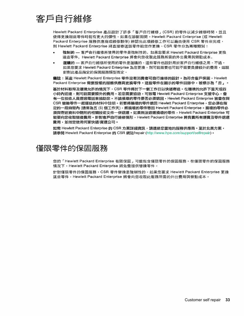
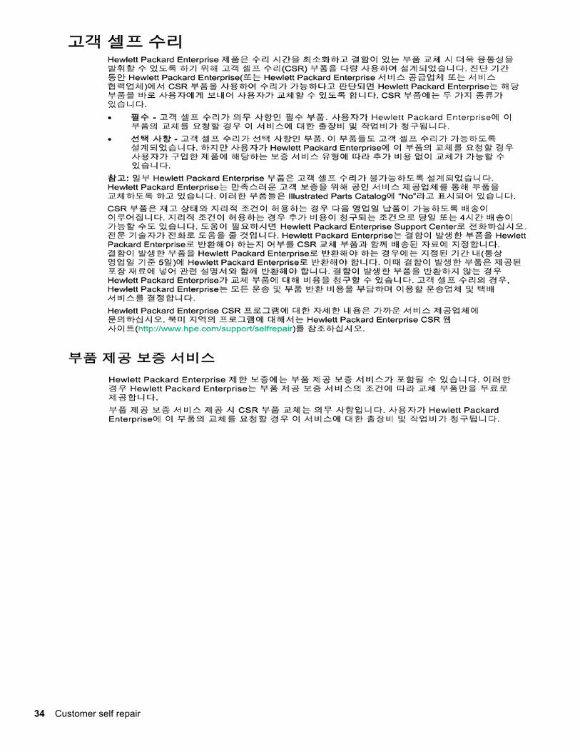
Customer self repairHewlett Packard Enterprise products are designed with many Customer Self Repair (CSR) parts to minimizerepair time and allow for greater flexibility in performing defective parts replacement. If during the diagnosisperiod Hewlett Packard Enterprise (or Hewlett Packard Enterprise service providers or service partners)identifies that the repair can be accomplished by the use of a CSR part, Hewlett Packard Enterprise will shipthat part directly to you for replacement. There are two categories of CSR parts:
• Mandatory—Parts for which customer self repair is mandatory. If you request Hewlett Packard Enterpriseto replace these parts, you will be charged for the travel and labor costs of this service.
• Optional—Parts for which customer self repair is optional. These parts are also designed for customerself repair. If, however, you require that Hewlett Packard Enterprise replace them for you, there may ormay not be additional charges, depending on the type of warranty service designated for your product.
NOTE: Some Hewlett Packard Enterprise parts are not designed for customer self repair. In order tosatisfy the customer warranty, Hewlett Packard Enterprise requires that an authorized service providerreplace the part. These parts are identified as "No" in the Illustrated Parts Catalog.
Based on availability and where geography permits, CSR parts will be shipped for next business day delivery.Same day or four-hour delivery may be offered at an additional charge where geography permits. Ifassistance is required, you can call the Hewlett Packard Enterprise Support Center and a technician will helpyou over the telephone. Hewlett Packard Enterprise specifies in the materials shipped with a replacementCSR part whether a defective part must be returned to Hewlett Packard Enterprise. In cases where it isrequired to return the defective part to Hewlett Packard Enterprise, you must ship the defective part back toHewlett Packard Enterprise within a defined period of time, normally five (5) business days. The defective partmust be returned with the associated documentation in the provided shipping material. Failure to return thedefective part may result in Hewlett Packard Enterprise billing you for the replacement. With a customer selfrepair, Hewlett Packard Enterprise will pay all shipping and part return costs and determine the courier/carrierto be used.
For more information about the Hewlett Packard Enterprise CSR program, contact your local service provider.For the North American program, go to the Hewlett Packard Enterprise CSR website.
Parts only warranty service
Your Hewlett Packard Enterprise Limited Warranty may include a parts only warranty service. Under the termsof parts only warranty service, Hewlett Packard Enterprise will provide replacement parts free of charge.
For parts only warranty service, CSR part replacement is mandatory. If you request Hewlett PackardEnterprise to replace these parts, you will be charged for the travel and labor costs of this service.
Réparation par le client (CSR)
Les produits Hewlett Packard Enterprise comportent de nombreuses pièces CSR (Customer Self Repair =réparation par le client) afin de minimiser les délais de réparation et faciliter le remplacement des piècesdéfectueuses. Si pendant la période de diagnostic, Hewlett Packard Enterprise (ou ses partenaires oumainteneurs agréés) détermine que la réparation peut être effectuée à l'aide d'une pièce CSR, HewlettPackard Enterprise vous l'envoie directement. Il existe deux catégories de pièces CSR :
• Obligatoire—Pièces pour lesquelles la réparation par le client est obligatoire. Si vous demandez àHewlett Packard Enterprise de remplacer ces pièces, les coûts de déplacement et main d'œuvre duservice vous seront facturés.
• Facultatif—Pièces pour lesquelles la réparation par le client est facultative. Ces pièces sont égalementconçues pour permettre au client d'effectuer lui-même la réparation. Toutefois, si vous demandez àHewlett Packard Enterprise de remplacer ces pièces, l'intervention peut ou non vous être facturée, selonle type de garantie applicable à votre produit.
Customer self repair 25

REMARQUE: Certaines pièces Hewlett Packard Enterprise ne sont pas conçues pour permettre au clientd'effectuer lui-même la réparation. Pour que la garantie puisse s'appliquer, Hewlett Packard Enterprise exigeque le remplacement de la pièce soit effectué par un Mainteneur Agréé. Ces pièces sont identifiées par lamention "Non" dans le Catalogue illustré.
Les pièces CSR sont livrées le jour ouvré suivant, dans la limite des stocks disponibles et selon votresituation géographique. Si votre situation géographique le permet et que vous demandez une livraison le jourmême ou dans les 4 heures, celle-ci vous sera facturée. Pour toute assistance, appelez le Centred’assistance Hewlett Packard Enterprise pour qu’un technicien vous aide au téléphone Dans les documentsenvoyés avec la pièce de rechange CSR, Hewlett Packard Enterprise précise s'il est nécessaire de luiretourner la pièce défectueuse. Si c'est le cas, vous devez le faire dans le délai indiqué, généralement cinq(5) jours ouvrés. La pièce et sa documentation doivent être retournées dans l'emballage fourni. Si vous neretournez pas la pièce défectueuse, Hewlett Packard Enterprise se réserve le droit de vous facturer les coûtsde remplacement. Dans le cas d'une pièce CSR, Hewlett Packard Enterprise supporte l'ensemble des fraisd'expédition et de retour, et détermine la société de courses ou le transporteur à utiliser.
Pour plus d'informations sur le programme CSR de Hewlett Packard Enterprise, contactez votre MainteneurAgrée local. Pour plus d'informations sur ce programme en Amérique du Nord, consultez le site Web HewlettPackard Enterprise.
Service de garantie "pièces seules"
Votre garantie limitée Hewlett Packard Enterprise peut inclure un service de garantie "pièces seules". Dansce cas, les pièces de rechange fournies par Hewlett Packard Enterprise ne sont pas facturées.
Dans le cadre de ce service, la réparation des pièces CSR par le client est obligatoire. Si vous demandez àHewlett Packard Enterprise de remplacer ces pièces, les coûts de déplacement et main d'œuvre du servicevous seront facturés.
Riparazione da parte del cliente
Per abbreviare i tempi di riparazione e garantire una maggiore flessibilità nella sostituzione di parti difettose, iprodotti Hewlett Packard Enterprise sono realizzati con numerosi componenti che possono essere riparatidirettamente dal cliente (CSR, Customer Self Repair). Se in fase di diagnostica Hewlett Packard Enterprise (oun centro di servizi o di assistenza Hewlett Packard Enterprise) identifica il guasto come riparabile medianteun ricambio CSR, Hewlett Packard Enterprise lo spedirà direttamente al cliente per la sostituzione. Vi sonodue categorie di parti CSR:
• Obbligatorie—Parti che devono essere necessariamente riparate dal cliente. Se il cliente ne affida lariparazione ad Hewlett Packard Enterprise, deve sostenere le spese di spedizione e di manodopera per ilservizio.
• Opzionali—Parti la cui riparazione da parte del cliente è facoltativa. Si tratta comunque di componentiprogettati per questo scopo. Se tuttavia il cliente ne richiede la sostituzione ad Hewlett Packard Enterprise,potrebbe dover sostenere spese addizionali a seconda del tipo di garanzia previsto per il prodotto.
NOTA: alcuni componenti Hewlett Packard Enterprise non sono progettati per la riparazione da parte delcliente. Per rispettare la garanzia, Hewlett Packard Enterprise richiede che queste parti siano sostituite da uncentro di assistenza autorizzato. Tali parti sono identificate da un "No" nel Catalogo illustrato dei componenti.
In base alla disponibilità e alla località geografica, le parti CSR vengono spedite con consegna entro il giornolavorativo seguente. La consegna nel giorno stesso o entro quattro ore è offerta con un supplemento di costosolo in alcune zone. In caso di necessità si può richiedere l'assistenza telefonica di un addetto del centro disupporto tecnico Hewlett Packard Enterprise. Nel materiale fornito con una parte di ricambio CSR, HewlettPackard Enterprise specifica se il cliente deve restituire dei component. Qualora sia richiesta la resa adHewlett Packard Enterprise del componente difettoso, lo si deve spedire ad Hewlett Packard Enterprise entroun determinato periodo di tempo, generalmente cinque (5) giorni lavorativi. Il componente difettoso deveessere restituito con la documentazione associata nell'imballo di spedizione fornito. La mancata restituzionedel componente può comportare la fatturazione del ricambio da parte di Hewlett Packard Enterprise. Nel casodi riparazione da parte del cliente, Hewlett Packard Enterprise sostiene tutte le spese di spedizione e resa esceglie il corriere/vettore da utilizzare.
26 Customer self repair

Per ulteriori informazioni sul programma CSR di Hewlett Packard Enterprise, contattare il centro di assistenzadi zona. Per il programma in Nord America fare riferimento al sito Web.
Servizio di garanzia per i soli componenti
La garanzia limitata Hewlett Packard Enterprise può includere un servizio di garanzia per i soli componenti.Nei termini di garanzia del servizio per i soli componenti, Hewlett Packard Enterprise fornirà gratuitamente leparti di ricambio.
Per il servizio di garanzia per i soli componenti è obbligatoria la formula CSR che prevede la riparazione daparte del cliente. Se il cliente invece richiede la sostituzione ad Hewlett Packard Enterprise dovrà sostenere lespese di spedizione e di manodopera per il servizio.
Customer Self Repair
Hewlett Packard Enterprise Produkte enthalten viele CSR-Teile (Customer Self Repair), um Reparaturzeitenzu minimieren und höhere Flexibilität beim Austausch defekter Bauteile zu ermöglichen. Wenn HewlettPackard Enterprise (oder ein Hewlett Packard Enterprise Servicepartner) bei der Diagnose feststellt, dass dasProdukt mithilfe eines CSR-Teils repariert werden kann, sendet Ihnen Hewlett Packard Enterprise diesesBauteil zum Austausch direkt zu. CSR-Teile werden in zwei Kategorien unterteilt:
• Zwingend—Teile, für die das Customer Self Repair-Verfahren zwingend vorgegeben ist. Wenn Sie denAustausch dieser Teile von Hewlett Packard Enterprise vornehmen lassen, werden Ihnen die Anfahrt- undArbeitskosten für diesen Service berechnet.
• Optional—Teile, für die das Customer Self Repair-Verfahren optional ist. Diese Teile sind auch fürCustomer Self Repair ausgelegt. Wenn Sie jedoch den Austausch dieser Teile von Hewlett PackardEnterprise vornehmen lassen möchten, können bei diesem Service je nach den für Ihr Produktvorgesehenen Garantiebedingungen zusätzliche Kosten anfallen.
HINWEIS: Einige Hewlett Packard Enterprise Teile sind nicht für Customer Self Repair ausgelegt. Um denGarantieanspruch des Kunden zu erfüllen, muss das Teil von einem Hewlett Packard EnterpriseServicepartner ersetzt werden. Im illustrierten Teilekatalog sind diese Teile mit „No“ bzw.„Nein“ gekennzeichnet.
CSR-Teile werden abhängig von der Verfügbarkeit und vom Lieferziel am folgenden Geschäftstag geliefert.Für bestimmte Standorte ist eine Lieferung am selben Tag oder innerhalb von vier Stunden gegen einenAufpreis verfügbar. Wenn Sie Hilfe benötigen, können Sie das Hewlett Packard Enterprise Support Centeranrufen und sich von einem Mitarbeiter per Telefon helfen lassen. Den Materialien von Hewlett PackardEnterprise, die mit einem CSR-Ersatzteil geliefert werden, können Sie entnehmen, ob das defekte Teil anHewlett Packard Enterprise zurückgeschickt werden muss. Wenn es erforderlich ist, das defekte Teil anHewlett Packard Enterprise zurückzuschicken, müssen Sie dies innerhalb eines vorgegebenen Zeitraums tun,in der Regel innerhalb von fünf (5) Geschäftstagen. Das defekte Teil muss mit der zugehörigenDokumentation in der Verpackung zurückgeschickt werden, die im Lieferumfang enthalten ist. Wenn Sie dasdefekte Teil nicht zurückschicken, kann Hewlett Packard Enterprise Ihnen das Ersatzteil in Rechnung stellen.Im Falle von Customer Self Repair kommt Hewlett Packard Enterprise für alle Kosten für die Lieferung undRücksendung auf und bestimmt den Kurier-/Frachtdienst.
Weitere Informationen über das Hewlett Packard Enterprise Customer Self Repair Programm erhalten Sievon Ihrem Servicepartner vor Ort. Informationen über das CSR-Programm in Nordamerika finden Sie auf der Hewlett Packard Enterprise Website unter.
Parts-only Warranty Service (Garantieservice ausschließlich für Teile)
Ihre Hewlett Packard Enterprise Garantie umfasst möglicherweise einen Parts-only Warranty Service(Garantieservice ausschließlich für Teile). Gemäß den Bestimmungen des Parts-only Warranty Service stelltHewlett Packard Enterprise Ersatzteile kostenlos zur Verfügung.
Für den Parts-only Warranty Service ist das CSR-Verfahren zwingend vorgegeben. Wenn Sie den Austauschdieser Teile von Hewlett Packard Enterprise vornehmen lassen, werden Ihnen die Anfahrt- und Arbeitskostenfür diesen Service berechnet.
Customer self repair 27

Reparaciones del propio cliente
Los productos de Hewlett Packard Enterprise incluyen muchos componentes que el propio usuario puedereemplazar (Customer Self Repair, CSR) para minimizar el tiempo de reparación y ofrecer una mayorflexibilidad a la hora de realizar sustituciones de componentes defectuosos. Si, durante la fase dediagnóstico, Hewlett Packard Enterprise (o los proveedores o socios de servicio de Hewlett PackardEnterprise) identifica que una reparación puede llevarse a cabo mediante el uso de un componente CSR,Hewlett Packard Enterprise le enviará dicho componente directamente para que realice su sustitución. Loscomponentes CSR se clasifican en dos categorías:
• Obligatorio—Componentes cuya reparación por parte del usuario es obligatoria. Si solicita a HewlettPackard Enterprise que realice la sustitución de estos componentes, tendrá que hacerse cargo de losgastos de desplazamiento y de mano de obra de dicho servicio.
• Opcional—Componentes cuya reparación por parte del usuario es opcional. Estos componentes tambiénestán diseñados para que puedan ser reparados por el usuario. Sin embargo, si precisa que HewlettPackard Enterprise realice su sustitución, puede o no conllevar costes adicionales, dependiendo del tipode servicio de garantía correspondiente al producto.
NOTA: Algunos componentes de Hewlett Packard Enterprise no están diseñados para que puedan serreparados por el usuario. Para que el usuario haga valer su garantía, Hewlett Packard Enterprise pone comocondición que un proveedor de servicios autorizado realice la sustitución de estos componentes. Dichoscomponentes se identifican con la palabra "No" en el catálogo ilustrado de componentes.
Según la disponibilidad y la situación geográfica, los componentes CSR se enviarán para que lleguen a sudestino al siguiente día laborable. Si la situación geográfica lo permite, se puede solicitar la entrega en elmismo día o en cuatro horas con un coste adicional. Si precisa asistencia técnica, puede llamar al Centro deasistencia técnica de Hewlett Packard Enterprise y recibirá ayuda telefónica por parte de un técnico. Con elenvío de materiales para la sustitución de componentes CSR, Hewlett Packard Enterprise especificará si loscomponentes defectuosos deberán devolverse a Hewlett Packard Enterprise. En aquellos casos en los quesea necesario devolver algún componente a Hewlett Packard Enterprise, deberá hacerlo en el periodo detiempo especificado, normalmente cinco días laborables. Los componentes defectuosos deberán devolversecon toda la documentación relacionada y con el embalaje de envío. Si no enviara el componente defectuosorequerido, Hewlett Packard Enterprise podrá cobrarle por el de sustitución. En el caso de todas sustitucionesque lleve a cabo el cliente, Hewlett Packard Enterprise se hará cargo de todos los gastos de envío ydevolución de componentes y escogerá la empresa de transporte que se utilice para dicho servicio.
Para obtener más información acerca del programa de Reparaciones del propio cliente de Hewlett PackardEnterprise, póngase en contacto con su proveedor de servicios local. Si está interesado en el programa paraNorteamérica, visite la página web de Hewlett Packard Enterprise CSR.
Servicio de garantía exclusivo de componentes
La garantía limitada de Hewlett Packard Enterprise puede que incluya un servicio de garantía exclusivo decomponentes. Según las condiciones de este servicio exclusivo de componentes, Hewlett Packard Enterprisele facilitará los componentes de repuesto sin cargo adicional alguno.
Para este servicio de garantía exclusivo de componentes, es obligatoria la sustitución de componentes porparte del usuario (CSR). Si solicita a Hewlett Packard Enterprise que realice la sustitución de estoscomponentes, tendrá que hacerse cargo de los gastos de desplazamiento y de mano de obra de dichoservicio.
Customer Self Repair
Veel onderdelen in Hewlett Packard Enterprise producten zijn door de klant zelf te repareren, waardoor dereparatieduur tot een minimum beperkt kan blijven en de flexibiliteit in het vervangen van defecte onderdelengroter is. Deze onderdelen worden CSR-onderdelen (Customer Self Repair) genoemd. Als Hewlett PackardEnterprise (of een Hewlett Packard Enterprise Service Partner) bij de diagnose vaststelt dat de reparatie kanworden uitgevoerd met een CSR-onderdeel, verzendt Hewlett Packard Enterprise dat onderdeel rechtstreeksnaar u, zodat u het defecte onderdeel daarmee kunt vervangen. Er zijn twee categorieën CSR-onderdelen:
28 Customer self repair

• Verplicht—Onderdelen waarvoor reparatie door de klant verplicht is. Als u Hewlett Packard Enterpriseverzoekt deze onderdelen voor u te vervangen, worden u voor deze service reiskosten en arbeidsloon inrekening gebracht.
• Optioneel—Onderdelen waarvoor reparatie door de klant optioneel is. Ook deze onderdelen zijnontworpen voor reparatie door de klant. Als u echter Hewlett Packard Enterprise verzoekt dezeonderdelen voor u te vervangen, kunnen daarvoor extra kosten in rekening worden gebracht, afhankelijkvan het type garantieservice voor het product.
OPMERKING: Sommige Hewlett Packard Enterprise onderdelen zijn niet ontwikkeld voor reparatie door deklant. In verband met de garantievoorwaarden moet het onderdeel door een geautoriseerde Service Partnerworden vervangen. Deze onderdelen worden in de geïllustreerde onderdelencatalogus aangemerkt met"Nee".
Afhankelijk van de leverbaarheid en de locatie worden CSR-onderdelen verzonden voor levering op deeerstvolgende werkdag. Levering op dezelfde dag of binnen vier uur kan tegen meerkosten wordenaangeboden, indien dit mogelijk is gezien de locatie. Indien assistentie is gewenst, belt u het Hewlett PackardEnterprise Support Center om via de telefoon ondersteuning van een technicus te ontvangen. HewlettPackard Enterprise vermeldt in de documentatie bij het vervangende CSR-onderdeel of het defecte onderdeelaan Hewlett Packard Enterprise moet worden geretourneerd. Als het defecte onderdeel aan Hewlett PackardEnterprise moet worden teruggezonden, moet u het defecte onderdeel binnen een bepaalde periode,gewoonlijk vijf (5) werkdagen, retourneren aan Hewlett Packard Enterprise. Het defecte onderdeel moet metde bijbehorende documentatie worden geretourneerd in het meegeleverde verpakkingsmateriaal. Als u hetdefecte onderdeel niet terugzendt, kan Hewlett Packard Enterprise u voor het vervangende onderdeel kostenin rekening brengen. Bij reparatie door de klant betaalt Hewlett Packard Enterprise alle verzendkosten voorhet vervangende en geretourneerde onderdeel en kiest Hewlett Packard Enterprise zelf welke koerier/transportonderneming hiervoor wordt gebruikt.
Neem contact op met een Service Partner voor meer informatie over het Customer Self Repair programmavan Hewlett Packard Enterprise. Informatie over Service Partners vindt u op de Hewlett Packard Enterprisewebsite.
Garantieservice "Parts Only"
Het is mogelijk dat de Hewlett Packard Enterprise garantie alleen de garantieservice "Parts Only" omvat.Volgens de bepalingen van de Parts Only garantieservice zal Hewlett Packard Enterprise kosteloosvervangende onderdelen ter beschikking stellen.
Voor de Parts Only garantieservice is vervanging door CSR-onderdelen verplicht. Als u Hewlett PackardEnterprise verzoekt deze onderdelen voor u te vervangen, worden u voor deze service reiskosten enarbeidsloon in rekening gebracht
Reparo feito pelo cliente
Os produtos da Hewlett Packard Enterprise são projetados com muitas peças para reparo feito pelo cliente(CSR) de modo a minimizar o tempo de reparo e permitir maior flexibilidade na substituição de peças comdefeito. Se, durante o período de diagnóstico, a Hewlett Packard Enterprise (ou fornecedores/parceiros daHewlett Packard Enterprise) concluir que o reparo pode ser efetuado pelo uso de uma peça CSR, a HewlettPackard Enterprise enviará a peça diretamente ao cliente. Há duas categorias de peças CSR:
• Obrigatória—Peças cujo reparo feito pelo cliente é obrigatório. Se desejar que a Hewlett PackardEnterprise substitua essas peças, serão cobradas as despesas de transporte e mão-de-obra do serviço.
• Opcional—Peças cujo reparo feito pelo cliente é opcional. Essas peças também são projetadas para oreparo feito pelo cliente. No entanto, se desejar que a Hewlett Packard Enterprise as substitua, podehaver ou não a cobrança de taxa adicional, dependendo do tipo de serviço de garantia destinado aoproduto.
OBSERVAÇÃO: Algumas peças da Hewlett Packard Enterprise não são projetadas para o reparo feito pelocliente. A fim de cumprir a garantia do cliente, a Hewlett Packard Enterprise exige que um técnico autorizadosubstitua a peça. Essas peças estão identificadas com a marca "No" (Não), no catálogo de peças ilustrado.
Customer self repair 29

Conforme a disponibilidade e o local geográfico, as peças CSR serão enviadas no primeiro dia útil após opedido. Onde as condições geográficas permitirem, a entrega no mesmo dia ou em quatro horas pode serfeita mediante uma taxa adicional. Se precisar de auxílio, entre em contato com o Centro de suporte técnicoda Hewlett Packard Enterprise para que um técnico o ajude por telefone. A Hewlett Packard Enterpriseespecifica nos materiais fornecidos com a peça CSR de reposição se a peça com defeito deve ser devolvidaà Hewlett Packard Enterprise. Nos casos em que isso for necessário, é preciso enviar a peça com defeito àHewlett Packard Enterprise, você deverá enviar a peça com defeito de volta para a Hewlett PackardEnterprise dentro do período de tempo definido, normalmente em 5 (cinco) dias úteis. A peça com defeitodeve ser enviada com a documentação correspondente no material de transporte fornecido. Caso não o faça,a Hewlett Packard Enterprise poderá cobrar a reposição. Para as peças de reparo feito pelo cliente, aHewlett Packard Enterprise paga todas as despesas de transporte e de devolução da peça e determina atransportadora/serviço postal a ser utilizado.
Para obter mais informações sobre o programa de reparo feito pelo cliente da Hewlett Packard Enterprise,entre em contato com o fornecedor de serviços local. Para o programa norte-americano, visite o site daHewlett Packard Enterprise.
Serviço de garantia apenas para peças
A garantia limitada da Hewlett Packard Enterprise pode incluir um serviço de garantia apenas para peças.Segundo os termos do serviço de garantia apenas para peças, a Hewlett Packard Enterprise fornece aspeças de reposição sem cobrar nenhuma taxa.
No caso desse serviço, a substituição de peças CSR é obrigatória. Se desejar que a Hewlett PackardEnterprise substitua essas peças, serão cobradas as despesas de transporte e mão-de-obra do serviço.
30 Customer self repair

Customer self repair 31

32 Customer self repair
Customer self repair 33
34 Customer self repair

Removal and replacement proceduresRequired tools
You need the following items for some procedures:
• T-10 Torx screwdriver• T-15 Torx screwdriver• T-30 Torx screwdriver
Safety considerationsBefore performing service procedures, review all the safety information.
Preventing electrostatic dischargeTo prevent damaging the system, be aware of the precautions you must follow when setting up the system orhandling parts. A discharge of static electricity from a finger or other conductor may damage system boards orother static-sensitive devices. This type of damage may reduce the life expectancy of the device.
Procedure
• Avoid hand contact by transporting and storing products in static-safe containers.• Keep electrostatic-sensitive parts in their containers until they arrive at static-free workstations.• Place parts on a grounded surface before removing them from their containers.• Avoid touching pins, leads, or circuitry.• Always be properly grounded when touching a static-sensitive component or assembly.
Symbols on equipmentThe following symbols might be found on the equipment to indicate the presence of potentially hazardousconditions.
This symbol indicates the presence of hazardous energy circuits or electric shockhazards. Refer all servicing to qualified personnel.
WARNING: To reduce the risk of injury from electric shock hazards, do not open thisenclosure. Refer all maintenance, upgrades, and servicing to qualified personnel.
This symbol indicates the presence of electric shock hazards. The area contains no useror field serviceable parts. Do not open for any reason.
WARNING: To reduce the risk of injury from electric shock hazards, do not open thisenclosure.
This symbol on an RJ-45 receptacle indicates a network interface connection.
WARNING: To reduce the risk of electric shock, fire, or damage to the equipment, do notplug telephone or telecommunications connectors into this receptacle.
Removal and replacement procedures 35

This symbol indicates the presence of a hot surface or hot component. If this surface iscontacted, the potential for injury exists.
WARNING: To reduce the risk of injury from a hot component, allow the surface to coolbefore touching.
This symbol indicates that the component exceeds the recommended weight for oneindividual to handle safely.
WARNING: To reduce the risk of personal injury or damage to the equipment, observelocal occupational health and safety requirements and guidelines for manual materialhandling.
These symbols, on power supplies or systems, indicate that the equipment is supplied bymultiple sources of power.
WARNING: To reduce the risk of injury from electric shock, remove all power cords todisconnect power from the system completely.
Server warnings and cautionsBefore installing a server, be sure that you understand the following warnings and cautions.
WARNING:To reduce the risk of electric shock, personal injury, and damage to the equipment:
• Do not attempt to service any parts of the equipment other than those specified in the followingprocedure. Any other activities may require that you shut down the server and remove the powercord.
• Installation and maintenance of this product must be performed by individuals who areknowledgeable about the procedures, precautions and hazards associated with the product.
WARNING:To reduce the risk of personal injury from hot surfaces, allow the drives and the internal systemcomponents to cool before touching them.
CAUTION:Do not operate the server for long periods with the access panel open or removed. Operating the serverin this manner results in improper airflow and improper cooling that can lead to thermal damage.
Preparation proceduresPower down the server
Before powering down the server for any upgrade or maintenance procedures, perform a backup of criticalserver data and programs.
IMPORTANT:When the server is in standby mode, auxiliary power is still being provided to the system.
To power down the server, use one of the following methods:
• Press and release the Power On/Standby button.
36 Server warnings and cautions

This method initiates a controlled shutdown of applications and the OS before the server enters standbymode.
• Press and hold the Power On/Standby button for more than 4 seconds to force the server to enter standbymode.
This method forces the server to enter standby mode without properly exiting applications and the OS. Ifan application stops responding, you can use this method to force a shutdown.
• Use a virtual power button selection through iLO.
This method initiates a controlled remote shutdown of applications and the OS before the server entersstandby mode.
Before proceeding, verify that the server is in standby mode by observing that the system power LED isamber.
Extend the server from the rack
WARNING:To reduce the risk of personal injury or equipment damage, be sure that the rack is adequately stabilizedbefore extending a component from the rack.
1. Pull down the quick release levers on each side of the server.2. Extend the server from the rack.
3. After performing the installation or maintenance procedure, slide the server back into the rack, and thenpress the server firmly into the rack to secure it in place.
WARNING:To reduce the risk of personal injury, be careful when pressing the server rail-release latches andsliding the server into the rack. The sliding rails could pinch your fingers.
Remove the server from the rackTo remove the server from a Hewlett Packard Enterprise, Compaq-branded, Telco, or third-party rack:
Procedure
1. Power down the server.2. Extend the server from the rack.
Extend the server from the rack 37
3. Disconnect the cabling and remove the server from the rack. For more information, see the documentationthat ships with the rack mounting option.
4. Place the server on a sturdy, level surface.
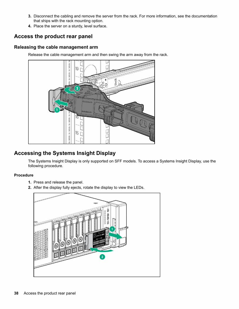
Access the product rear panel
Releasing the cable management armRelease the cable management arm and then swing the arm away from the rack.
Accessing the Systems Insight DisplayThe Systems Insight Display is only supported on SFF models. To access a Systems Insight Display, use thefollowing procedure.
Procedure
1. Press and release the panel.2. After the display fully ejects, rotate the display to view the LEDs.
38 Access the product rear panel

Remove the access panel
WARNING:To reduce the risk of personal injury from hot surfaces, allow the drives and the internal systemcomponents to cool before touching them.
CAUTION:Do not operate the server for long periods with the access panel open or removed. Operating the serverin this manner results in improper airflow and improper cooling that can lead to thermal damage.
To remove the component:
Procedure
1. Power down the server.2. Extend the server from the rack.3. Open or unlock the locking latch, slide the access panel to the rear of the chassis, and remove the access
panel.
Release the full-length expansion board retainer
Procedure
1. Power down the server (Power down the server on page 36).2. Remove all power:
a. Disconnect each power cord from the power source.b. Disconnect each power cord from the server.
3. Do one of the following:
• Extend the server from the rack (Extend the server from the rack on page 37).• Remove the server from the rack (Remove the server from the rack on page 37).
4. Remove the access panel (Remove the access panel on page 39).5. Remove the air baffle (Removing the air baffle on page 44).6. Remove the air baffle diverters.
7. Install the air baffle.8. Release the full-length expansion board retainer.
Remove the access panel 39

To replace the component, reverse the removal procedure.
Removing and replacing a drive blankCAUTION:To prevent improper cooling and thermal damage, do not operate the server unless all bays arepopulated with either a component or a blank.
Procedure
1. Remove the drive blank.
2. To replace the blank, slide the blank into the bay until it locks into place.
Removing and replacing drives
Removing and replacing a hot-plug drive
CAUTION:To prevent improper cooling and thermal damage, do not operate the server unless all bays arepopulated with either a component or a blank.
40 Removing and replacing a drive blank

Procedure
1. Back up all server data on the drive.2. Determine the status of the drive from the drive LED definitions (SAS/SATA drive components and LEDs
on page 101).3. Remove the drive.
To replace the component, reverse the removal procedure.
Removing and replacing an NVMe driveAn NVMe SSD is a PCIe BUS device. Devices attached to a PCIe bus cannot be removed without allowingthe device and the bus to complete and cease signal/traffic flow.
Procedure
1. Back up all server data.2. Observe the LED status of the drive and determine if it can be removed.3. Remove the drive:
a. Push the Power button.The Do Not Remove button illuminates and flashes.
b. Wait until the flashing stops and the Do Not Remove button is no longer illuminated.c. Push the Do Not Remove button and then remove the drive.
Removing and replacing an M.2 SSD
Procedure
1. Power down the server (Power down the server on page 36).2. Remove all power:
a. Disconnect each power cord from the power source.b. Disconnect each power cord from the server.
3. Do one of the following:
Removing and replacing an NVMe drive 41

• Extend the server from the rack (Extend the server from the rack on page 37).• Remove the server from the rack (Remove the server from the rack on page 37).
4. Remove the access panel (Remove the access panel on page 39).5. Remove the primary riser cage (Removing and replacing the primary or secondary PCIe riser cages
on page 45).6. Remove the M.2 SSD.
To replace the component, reverse the removal procedure.
Removing and replacing the hot-plug fanProcedure
1. Extend the server from the rack (Extend the server from the rack on page 37).2. Remove the access panel (Remove the access panel on page 39).
CAUTION:Do not operate the server for long periods with the access panel open or removed. Operating theserver in this manner results in improper airflow and improper cooling that can lead to thermaldamage.
IMPORTANT:For optimum cooling, install fans in all primary fan locations.
For more information, refer to the fan locations table in the server user guide.3. Remove the fan.
42 Removing and replacing the hot-plug fan
To replace the component, reverse the removal procedure.
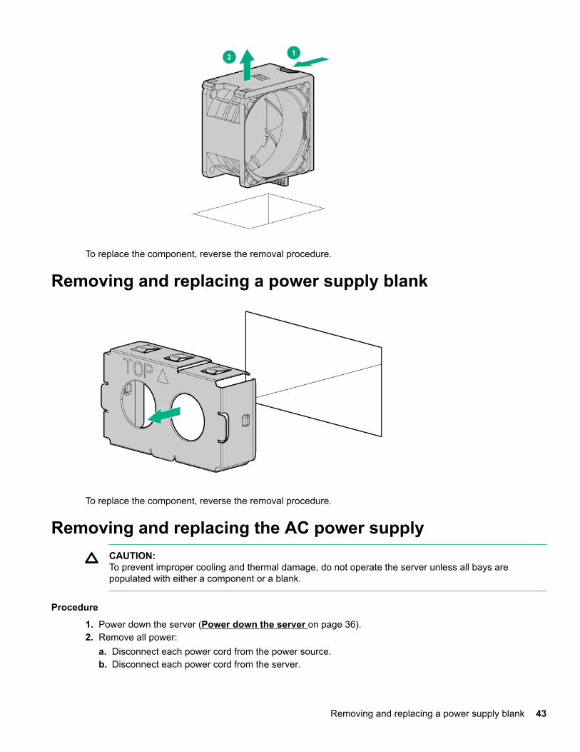
Removing and replacing a power supply blank
To replace the component, reverse the removal procedure.
Removing and replacing the AC power supplyCAUTION:To prevent improper cooling and thermal damage, do not operate the server unless all bays arepopulated with either a component or a blank.
Procedure
1. Power down the server (Power down the server on page 36).2. Remove all power:
a. Disconnect each power cord from the power source.b. Disconnect each power cord from the server.
Removing and replacing a power supply blank 43

3. Access the product rear panel (Access the product rear panel on page 38).4. Remove the power supply.
WARNING:To reduce the risk of personal injury from hot surfaces, allow the power supply or power supply blankto cool before touching it.
To replace the component, reverse the removal procedure.
Removing the air baffleCAUTION:Do not detach the cable that connects the battery pack to the cache module. Detaching the cablecauses any unsaved data in the cache module to be lost.
CAUTION:For proper cooling, do not operate the server without the access panel, baffles, expansion slot covers,or blanks installed. If the server supports hot-plug components, minimize the amount of time the accesspanel is open.
Procedure
1. Power down the server (Power down the server on page 36).2. Remove all power:
a. Disconnect each power cord from the power source.b. Disconnect each power cord from the server.
3. Do one of the following:
• Extend the server from the rack (Extend the server from the rack on page 37).• Remove the server from the rack (Remove the server from the rack on page 37).
4. Remove the access panel (Remove the access panel on page 39).5. Remove the air baffle.
44 Removing the air baffle

To replace the component, reverse the removal procedure.
Removing and replacing the primary or secondary PCIe risercages
CAUTION:To prevent improper cooling and thermal damage, do not operate the server unless all PCI slots haveeither an expansion slot cover or an expansion board installed.
Procedure
1. Power down the server (Power down the server on page 36).2. Remove all power:
a. Disconnect each power cord from the power source.b. Disconnect each power cord from the server.
3. Disconnect any external cables that are connected to the expansion board.4. Do one of the following:
• Extend the server from the rack (Extend the server from the rack on page 37).• Remove the server from the rack (Remove the server from the rack on page 37).
5. Remove the access panel (Remove the access panel on page 39).6. Disconnect any internal cables that are connected to the expansion board.7. If any full-length expansion boards are installed, release the full-length expansion board retainer (Release
the full-length expansion board retainer on page 39).8. Remove the PCIe riser cage.
Removing and replacing the primary or secondary PCIe riser cages 45

9. To replace the component, reverse the removal procedure.
To replace the component, reverse the removal procedure.
Removing and replacing the tertiary PCIe riser cageCAUTION:To prevent improper cooling and thermal damage, do not operate the server unless all PCI slots haveeither an expansion slot cover or an expansion board installed.
Procedure
1. Power down the server (Power down the server on page 36).2. Remove all power:
a. Disconnect each power cord from the power source.b. Disconnect each power cord from the server.
3. Disconnect any external cables that are connected to the expansion board.4. Do one of the following:
• Extend the server from the rack (Extend the server from the rack on page 37).• Remove the server from the rack (Remove the server from the rack on page 37).
5. Remove the access panel (Remove the access panel on page 39).6. Disconnect any internal cables that are connected to the expansion board.7. If any full-length expansion boards are installed, release the full-length expansion board retainer (Release
the full-length expansion board retainer on page 39).8. Remove the PCIe riser cage.
46 Removing and replacing the tertiary PCIe riser cage

To replace the component, reverse the removal procedure.
Removing and replacing the PCIe riser blankCAUTION:To prevent improper cooling and thermal damage, do not operate the server unless all PCI slots haveeither an expansion slot cover or an expansion board installed.
Procedure
1. Power down the server (Power down the server on page 36).2. Remove all power:
a. Disconnect each power cord from the power source.b. Disconnect each power cord from the server.
3. Do one of the following:
• Extend the server from the rack (Extend the server from the rack on page 37).• Remove the server from the rack (Remove the server from the rack on page 37).
4. Remove the access panel (Remove the access panel on page 39).5. Remove the PCIe riser blank:
• Primary or secondary
Removing and replacing the PCIe riser blank 47
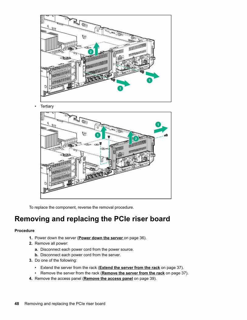
• Tertiary
To replace the component, reverse the removal procedure.
Removing and replacing the PCIe riser boardProcedure
1. Power down the server (Power down the server on page 36).2. Remove all power:
a. Disconnect each power cord from the power source.b. Disconnect each power cord from the server.
3. Do one of the following:
• Extend the server from the rack (Extend the server from the rack on page 37).• Remove the server from the rack (Remove the server from the rack on page 37).
4. Remove the access panel (Remove the access panel on page 39).
48 Removing and replacing the PCIe riser board

5. If any full-length expansion boards are installed, release the full-length expansion board retainer (Releasethe full-length expansion board retainer on page 39).
6. Remove the PCIe riser cage:
• Primary or secondary PCIe riser cage (Removing and replacing the primary or secondary PCIeriser cages on page 45)
• Tertiary PCIe riser cage (Removing and replacing the tertiary PCIe riser cage on page 46)7. Remove any expansion boards from the PCIe riser cage.8. Remove the PCIe riser board:
• Primary/secondary riser cage
• Tertiary riser cage
Removal and replacement procedures 49

To replace the component, reverse the removal procedure.
Removing and replacing an expansion slot blankWARNING:To reduce the risk of personal injury, electric shock, or damage to the equipment, remove power fromthe server by removing the power cord. The front panel Power On/Standby button does not shut offsystem power. Portions of the power supply and some internal circuitry remain active until AC power isremoved.
CAUTION:For proper cooling, do not operate the server without the access panel, baffles, expansion slot covers,or blanks installed. If the server supports hot-plug components, minimize the amount of time the accesspanel is open.
Procedure
1. Power down the server (Power down the server on page 36).2. Remove all power:
a. Disconnect each power cord from the power source.b. Disconnect each power cord from the server.
3. Do one of the following:
• Extend the server from the rack (Extend the server from the rack on page 37).• Remove the server from the rack (Remove the server from the rack on page 37).
4. Remove the access panel (Remove the access panel on page 39).5. Remove the PCIe riser cage:
• Primary or secondary PCIe riser cage (Removing and replacing the primary or secondary PCIeriser cages on page 45)
• Tertiary PCIe riser cage (Removing and replacing the tertiary PCIe riser cage on page 46)6. Remove the expansion slot blank.
50 Removing and replacing an expansion slot blank

To replace the component, reverse the removal procedure.
Removing and replacing an expansion boardWARNING:To reduce the risk of personal injury, electric shock, or damage to the equipment, remove power fromthe server by removing the power cord. The front panel Power On/Standby button does not shut offsystem power. Portions of the power supply and some internal circuitry remain active until AC power isremoved.
Procedure
1. Power down the server (Power down the server on page 36).2. Remove all power:
a. Disconnect each power cord from the power source.b. Disconnect each power cord from the server.
3. Disconnect any external cables that are connected to the expansion board.4. Do one of the following:
• Extend the server from the rack (Extend the server from the rack on page 37).• Remove the server from the rack (Remove the server from the rack on page 37).
5. Remove the access panel (Remove the access panel on page 39).6. Disconnect any internal cables that are connected to the expansion board.7. If any full-length expansion boards are installed, release the full-length expansion board retainer (Release
the full-length expansion board retainer on page 39).8. Remove the PCIe riser cage:
• Primary or secondary PCIe riser cage (Removing and replacing the primary or secondary PCIeriser cages on page 45)
• Tertiary PCIe riser cage (Removing and replacing the tertiary PCIe riser cage on page 46)9. Remove the expansion board.
Removing and replacing an expansion board 51

To replace the component, reverse the removal procedure.
Removing and replacing the fan cageProcedure
1. Power down the server (Power down the server on page 36).2. Remove all power:
a. Disconnect each power cord from the power source.b. Disconnect each power cord from the server.
3. Do one of the following:
• Extend the server from the rack (Extend the server from the rack on page 37).• Remove the server from the rack (Remove the server from the rack on page 37).
4. Remove the access panel (Remove the access panel on page 39).5. Remove the fan cage.
CAUTION:Do not operate the server for long periods with the access panel open or removed. Operating theserver in this manner results in improper airflow and improper cooling that can lead to thermaldamage.
52 Removing and replacing the fan cage

IMPORTANT:For optimum cooling, install fans in all primary fan locations.
For more information, refer to the fan locations table in the server user guide.
To replace the component, reverse the removal procedure.
Removing and replacing the FlexibleLOMProcedure
1. Power down the server (Power down the server on page 36).2. Remove all power:
a. Disconnect each power cord from the power source.b. Disconnect each power cord from the server.
3. Disconnect the LAN segment cables.4. Do one of the following:
• Extend the server from the rack (Extend the server from the rack on page 37).• Remove the server from the rack (Remove the server from the rack on page 37).
5. Remove the FlexibleLOM.
To replace the component, reverse the removal procedure.
Removing and replacing the small form factor universalmedia bayProcedure
1. Power down the server (Power down the server on page 36).2. Remove all power:
a. Disconnect each power cord from the power source.b. Disconnect each power cord from the server.
3. Do one of the following:
Removing and replacing the FlexibleLOM 53

• Extend the server from the rack (Extend the server from the rack on page 37).• Remove the server from the rack (Remove the server from the rack on page 37.
4. Remove the access panel (Remove the access panel on page 39).5. Remove all hot-plug hard drives (Removing and replacing drives on page 40).6. Remove the fan cage (Removing and replacing the fan cage on page 52) .7. Disconnect all cables from the universal media bay.8. Remove the universal media bay.
To replace the component, reverse the removal procedure.
Removing and replacing the LFF power switch moduleProcedure
1. Power down the server (Power down the server on page 36).2. Remove all power:
a. Disconnect each power cord from the power source.b. Disconnect each power cord from the server.
3. Do one of the following:
• Extend the server from the rack (Extend the server from the rack on page 37).• Remove the server from the rack (Remove the server from the rack on page 37).
4. Remove the access panel (Remove the access panel on page 39).5. Remove all hot-plug hard drives (Removing and replacing drives on page 40).6. Remove the fan cage (Removing and replacing the fan cage on page 52).7. Disconnect all cables connecting the power switch module to the system board and other components.8. Feeding the cables through the front of the server, remove the power switch module.
54 Removing and replacing the LFF power switch module

To replace the component, reverse the removal procedure.
Removing and replacing the SFF optical driveProcedure
1. Power down the server (Power down the server on page 36).2. Remove all power:
a. Disconnect each power cord from the power source.b. Disconnect each power cord from the server.
3. Do one of the following:
• Extend the server from the rack (Extend the server from the rack on page 37).• Remove the server from the rack (Remove the server from the rack on page 37).
4. Remove the access panel (Remove the access panel on page 39).5. Remove the fan cage (Removing and replacing the fan cage on page 52).6. Disconnect all cables from the SFF universal media bay.7. Remove the SFF universal media bay (Removing and replacing the small form factor universal
media bay on page 53).8. Remove the optical drive.
Removing and replacing the SFF optical drive 55

9. Remove the optical drive bracket, for use with the replacement optical drive.
10. Before replacing the component, install the optical drive bracket, retained from the optical drive you arereplacing.
56 Removal and replacement procedures

To replace the component, reverse the removal procedure.
Removing and replacing the LFF optical driveProcedure
1. Power down the server (Power down the server on page 36).2. Remove all power:
a. Disconnect each power cord from the power source.b. Disconnect each power cord from the server.
3. Do one of the following:
• Extend the server from the rack (Extend the server from the rack on page 37).• Remove the server from the rack (Remove the server from the rack on page 37).
4. Remove the access panel (Remove the access panel on page 39).5. Remove the fan cage (Removing and replacing the fan cage on page 52).6. Disconnect all cables from the LFF power switch module.7. Remove the LFF power switch module (Removing and replacing the LFF power switch module on
page 54).8. Remove the optical drive.
Removing and replacing the LFF optical drive 57

To replace the component, reverse the removal procedure.
Removing and replacing the 8-SFF drive cageProcedure
1. Power down the server (Power down the server on page 36).2. Remove all power:
a. Disconnect each power cord from the power source.b. Disconnect each power cord from the server.
3. Do one of the following:
• Extend the server from the rack (Extend the server from the rack on page 37).• Remove the server from the rack (Remove the server from the rack on page 37).
4. Remove the access panel (Remove the access panel on page 39).5. Remove all drives (Removing and replacing drives on page 40).6. Remove the fan cage (Removing and replacing the fan cage on page 52).7. Disconnect all cables from the drive backplane.8. Remove the drive cage.
To replace the component, reverse the removal procedure.
58 Removing and replacing the 8-SFF drive cage

Removing and replacing the 8-SFF drive backplaneProcedure
1. Power down the server (Power down the server on page 36).2. Remove all power:
a. Disconnect each power cord from the power source.b. Disconnect each power cord from the server.
3. Do one of the following:
• Extend the server from the rack (Extend the server from the rack on page 37).• Remove the server from the rack (Remove the server from the rack on page 37).
4. Remove the access panel (Remove the access panel on page 39).5. Remove the fan cage (Removing and replacing the fan cage on page 52).6. Remove all drives (Removing and replacing drives on page 40).7. Remove the 8 SFF drive cage (Removing and replacing the 8-SFF drive cage on page 58).8. Remove the drive backplane.
To replace the component, reverse the removal procedure.
Removing and replacing the 2-SFF front drive cageProcedure
1. Power down the server (Power down the server on page 36).2. Remove all power:
a. Disconnect each power cord from the power source.b. Disconnect each power cord from the server.
3. Do one of the following:
• Extend the server from the rack (Extend the server from the rack on page 37).• Remove the server from the rack (Remove the server from the rack on page 37).
4. Remove the access panel (Remove the access panel on page 39).5. Remove all drives (Removing and replacing drives on page 40).6. Disconnect all cables from the drive backplane.7. Remove the drive cage.
Removing and replacing the 8-SFF drive backplane 59
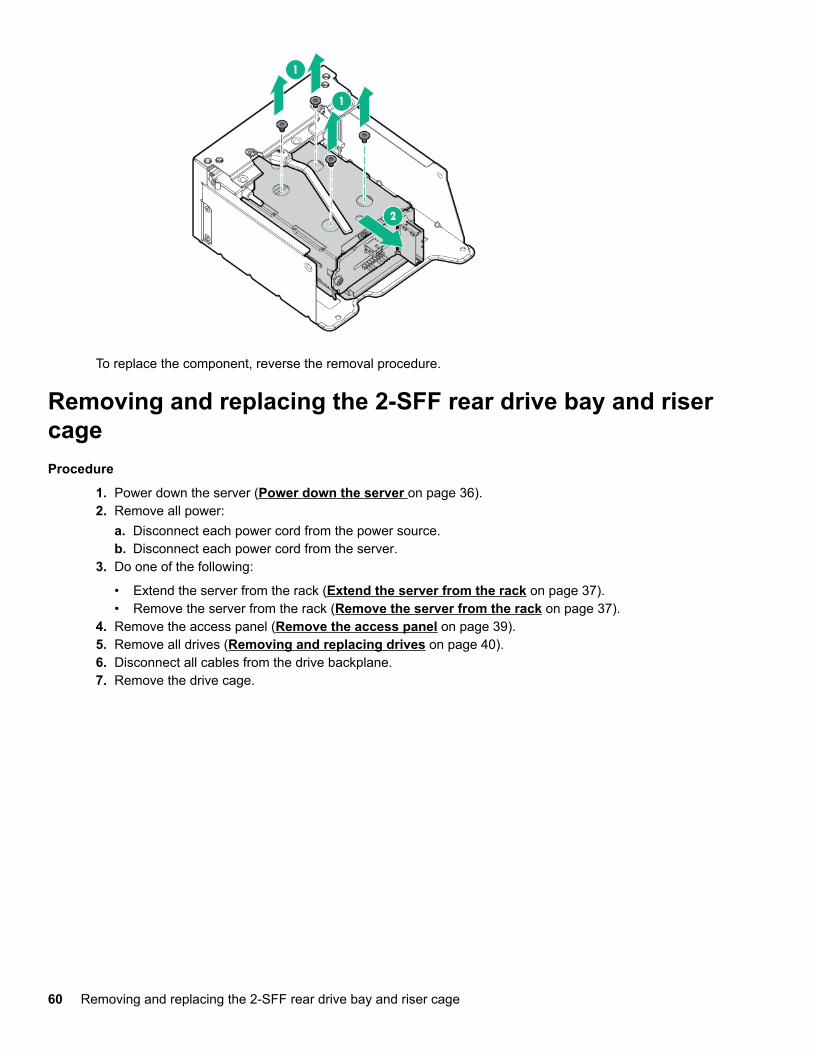
To replace the component, reverse the removal procedure.
Removing and replacing the 2-SFF rear drive bay and risercageProcedure
1. Power down the server (Power down the server on page 36).2. Remove all power:
a. Disconnect each power cord from the power source.b. Disconnect each power cord from the server.
3. Do one of the following:
• Extend the server from the rack (Extend the server from the rack on page 37).• Remove the server from the rack (Remove the server from the rack on page 37).
4. Remove the access panel (Remove the access panel on page 39).5. Remove all drives (Removing and replacing drives on page 40).6. Disconnect all cables from the drive backplane.7. Remove the drive cage.
60 Removing and replacing the 2-SFF rear drive bay and riser cage

To replace the component, reverse the removal procedure.
Removing and replacing the 2-SFF drive cageProcedure
1. Power down the server (Power down the server on page 36).2. Remove all power:
a. Disconnect each power cord from the power source.b. Disconnect each power cord from the server.
3. Do one of the following:
• Extend the server from the rack (Extend the server from the rack on page 37).• Remove the server from the rack (Remove the server from the rack on page 37).
4. Remove the access panel (Remove the access panel on page 39).5. Remove all drives (Removing and replacing drives on page 40).6. Disconnect all cables from the drive backplane.7. Remove the drive cage.
Removing and replacing the 2-SFF drive cage 61

To replace the component, reverse the removal procedure.
Removing and replacing the 2-SFF rear drive backplaneProcedure
1. Power down the server (Power down the server on page 36).2. Remove all power:
a. Disconnect each power cord from the power source.b. Disconnect each power cord from the server.
3. Do one of the following:
• Extend the server from the rack (Extend the server from the rack on page 37).• Remove the server from the rack (Remove the server from the rack on page 37).
4. Remove the access panel (Remove the access panel on page 39).5. Remove the fan cage (Removing and replacing the fan cage on page 52).6. Remove all drives (Removing and replacing drives on page 40).7. Remove the 2 SFF rear drive cage (Removing and replacing the 2-SFF drive cage on page 61).8. Remove the drive backplane.
62 Removing and replacing the 2-SFF rear drive backplane

To replace the component, reverse the removal procedure.
Removing and replacing a 4 LFF midplane cageProcedure
1. Power down the server (Power down the server on page 36).2. Remove all power:
a. Disconnect each power cord from the power source.b. Disconnect each power cord from the server.
3. Do one of the following:
• Extend the server from the rack (Extend the server from the rack on page 37).• Remove the server from the rack (Remove the server from the rack on page 37).
4. Remove the access panel (Remove the access panel on page 39).5. If installed, remove all riser cages:
• Primary or secondary PCIe riser cage (Removing and replacing the primary or secondary PCIeriser cages on page 45)
• Tertiary PCIe riser cage (Removing and replacing the tertiary PCIe riser cage on page 46)6. Disconnect the power and cables from the drive cage.7. Raise the blue tabs on the drive tray and lift the drive cage to a 15 degree angle.8. Pull the plunger pin to disengage it.9. Remove all drives (Removing and replacing drives on page 40).10. Using both hands, remove the drive cage from the server.
Removing and replacing a 4 LFF midplane cage 63

Removing and replacing a three-bay LFF rear drive cageProcedure
1. Power down the server (Power down the server on page 36).2. Remove all power:
a. Disconnect each power cord from the power source.b. Disconnect each power cord from the server.
3. Do one of the following:
• Extend the server from the rack (Extend the server from the rack on page 37).• Remove the server from the rack (Remove the server from the rack on page 37).
4. Remove the access panel (Remove the access panel on page 39).5. Remove all drives (Removing and replacing drives on page 40).6. Remove the drive cage.
To replace the component, reverse the removal procedure.
64 Removing and replacing a three-bay LFF rear drive cage
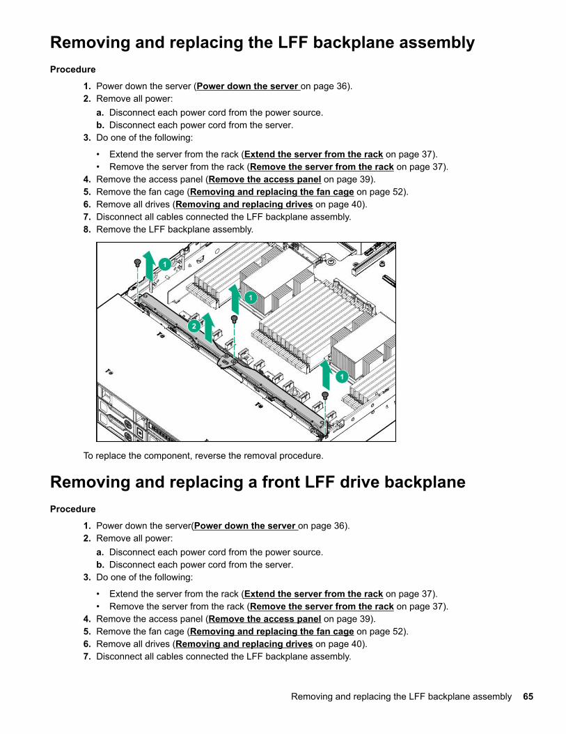
Removing and replacing the LFF backplane assemblyProcedure
1. Power down the server (Power down the server on page 36).2. Remove all power:
a. Disconnect each power cord from the power source.b. Disconnect each power cord from the server.
3. Do one of the following:
• Extend the server from the rack (Extend the server from the rack on page 37).• Remove the server from the rack (Remove the server from the rack on page 37).
4. Remove the access panel (Remove the access panel on page 39).5. Remove the fan cage (Removing and replacing the fan cage on page 52).6. Remove all drives (Removing and replacing drives on page 40).7. Disconnect all cables connected the LFF backplane assembly.8. Remove the LFF backplane assembly.
To replace the component, reverse the removal procedure.
Removing and replacing a front LFF drive backplaneProcedure
1. Power down the server(Power down the server on page 36).2. Remove all power:
a. Disconnect each power cord from the power source.b. Disconnect each power cord from the server.
3. Do one of the following:
• Extend the server from the rack (Extend the server from the rack on page 37).• Remove the server from the rack (Remove the server from the rack on page 37).
4. Remove the access panel (Remove the access panel on page 39).5. Remove the fan cage (Removing and replacing the fan cage on page 52).6. Remove all drives (Removing and replacing drives on page 40).7. Disconnect all cables connected the LFF backplane assembly.
Removing and replacing the LFF backplane assembly 65

8. Remove the LFF backplane assembly.
9. Remove the drive backplane.
To replace the component, reverse the removal procedure.
Removing and replacing the 3-LFF rear drive backplaneProcedure
1. Power down the server (Power down the server on page 36).2. Remove all power:
a. Disconnect each power cord from the power source.b. Disconnect each power cord from the server.
3. Do one of the following:
• Extend the server from the rack (Extend the server from the rack on page 37).• Remove the server from the rack (Remove the server from the rack on page 37).
4. Remove the access panel (Remove the access panel on page 39).5. Remove the fan cage (Removing and replacing the fan cage on page 52).
66 Removing and replacing the 3-LFF rear drive backplane

6. Remove all drives (Removing and replacing drives on page 40).7. Remove the drive backplane.
To replace the component, reverse the removal procedure.
Removing and replacing a rear serial port interface (primary/secondary)Procedure
1. Power down the server(Power down the server on page 36).2. Remove all power:
a. Disconnect each power cord from the power source.b. Disconnect each power cord from the server.
3. Do one of the following:
• Extend the server from the rack (Extend the server from the rack on page 37).• Remove the server from the rack (Remove the server from the rack on page 37).
4. Remove the access panel (Remove the access panel on page 39).5. Using a T-10 Torx screwdriver, remove the screws securing the serial port. Then, disconnect and remove
the serial cable.
Removing and replacing a rear serial port interface (primary/secondary) 67

To replace the component, reverse the removal procedure.
Removing and replacing a rear serial port interface (tertiaryriser)Procedure
1. Power down the server (Power down the server on page 36).2. Remove all power:
a. Disconnect each power cord from the power source.b. Disconnect each power cord from the server.
3. Do one of the following:
• Extend the server from the rack (Extend the server from the rack on page 37).• Remove the server from the rack (Remove the server from the rack on page 37).
4. Remove the access panel (Remove the access panel on page 39).5. Disconnect the cable.6. Remove the tertiary riser cage.7. Using a T-10 Torx screwdriver, remove the serial port interface.
68 Removing and replacing a rear serial port interface (tertiary riser)

To replace the component:8. Install the serial port interface.9. Connect the cable.10. Install the riser.
Removing and replacing an SFF power switch moduleProcedure
1. Power down the server (Power down the server on page 36).2. Do one of the following:
• Extend the server from the rack (Extend the server from the rack on page 37).• Remove the server from the rack (Remove the server from the rack on page 37).
3. Remove the access panel (Remove the access panel on page 39).4. Disconnect cables from the power switch module.5. Remove the power switch module.
To replace the component, reverse the removal procedure
Removing and replacing an SFF power switch module 69
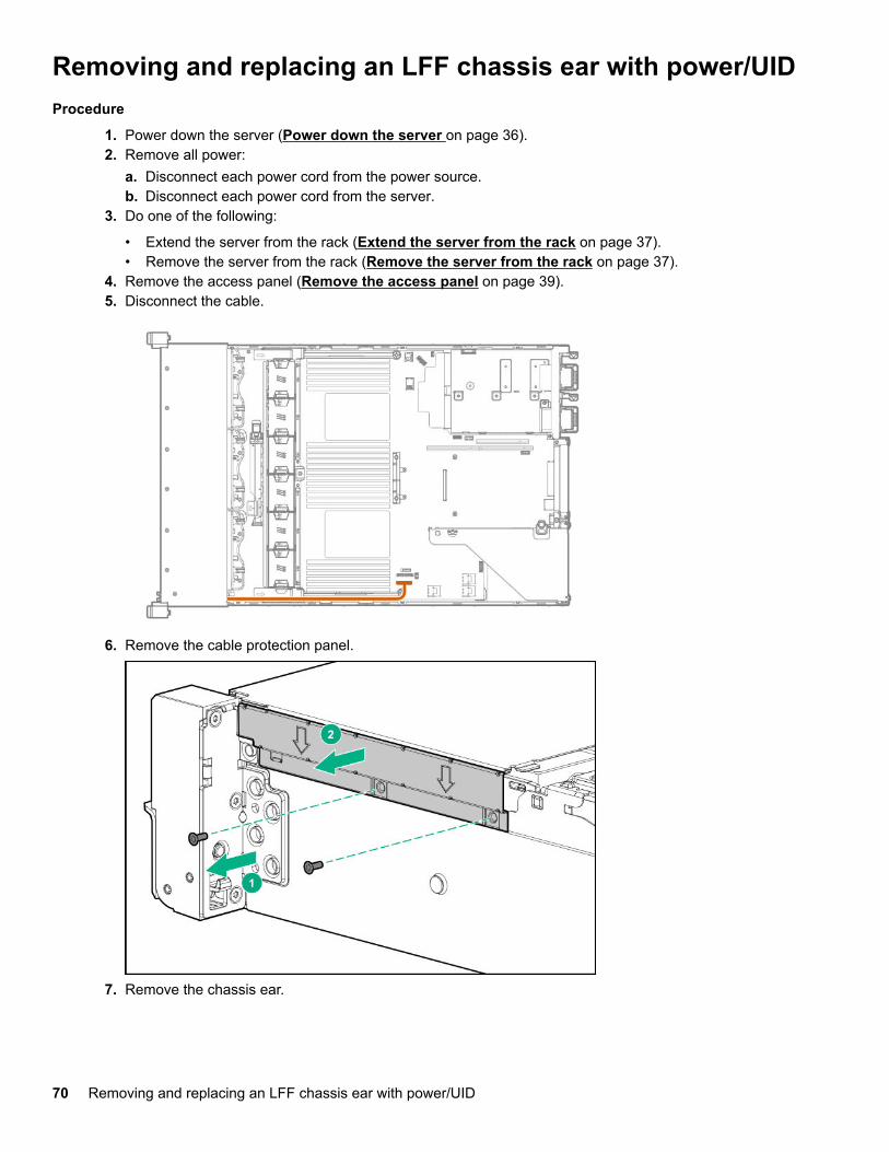
Removing and replacing an LFF chassis ear with power/UIDProcedure
1. Power down the server (Power down the server on page 36).2. Remove all power:
a. Disconnect each power cord from the power source.b. Disconnect each power cord from the server.
3. Do one of the following:
• Extend the server from the rack (Extend the server from the rack on page 37).• Remove the server from the rack (Remove the server from the rack on page 37).
4. Remove the access panel (Remove the access panel on page 39).5. Disconnect the cable.
6. Remove the cable protection panel.
7. Remove the chassis ear.
70 Removing and replacing an LFF chassis ear with power/UID

To replace the component, reverse the removal procedure.
Removing and replacing an SFF standard chassis earProcedure
1. Power down the server (Power down the server on page 36).2. Remove all power:
a. Disconnect each power cord from the power source.b. Disconnect each power cord from the server.
3. Do one of the following:
• Extend the server from the rack (Extend the server from the rack on page 37).• Remove the server from the rack (Remove the server from the rack on page 37).
4. Remove the chassis ear.
To replace the component, reverse the removal procedure.
Removing and replacing an SFF standard chassis ear 71

Removing and replacing a GPU enablement boardWARNING:To reduce the risk of personal injury, electric shock, or damage to the equipment, remove the powercord to remove power from the server. The front panel Power On/Standby button does not shut offsystem power. Portions of the power supply and some internal circuitry remain active until AC power isremoved.
CAUTION:To prevent improper cooling and thermal damage, do not operate the server unless all PCI slots haveeither an expansion slot cover or an expansion board installed.
Procedure
1. Power down the server(Power down the server on page 36).2. Remove all power:
a. Disconnect each power cord from the power source.b. Disconnect each power cord from the server.
3. Do one of the following:
• Extend the server from the rack (Extend the server from the rack on page 37).• Remove the server from the rack (Remove the server from the rack on page 37).
4. Remove the access panel (Remove the access panel on page 39).5. Remove the air baffle (Removing the air baffle on page 44).6. Release the full-length expansion board retainer (Release the full-length expansion board retainer on
page 39).7. Remove the riser cage.
• Removing and replacing the primary or secondary PCIe riser cages on page 45• Removing and replacing the tertiary PCIe riser cage on page 46
8. Disconnect the power cable from the GPU.9. Remove the GPU enablement board from the GPU-enabled riser cage.
• Primary or secondary riser cage
72 Removing and replacing a GPU enablement board

• Tertiary riser cage
To replace the component, reverse the removal procedure.
Removing and replacing a DIMMTo identify the DIMMs installed in the server, see "DIMM slot locations" in the server user guide.
Procedure
1. Power down the server (Power down the server on page 36).2. Remove all power:
a. Disconnect each power cord from the power source.b. Disconnect each power cord from the server.
3. Do one of the following:
• Extend the server from the rack (Extend the server from the rack on page 37).• Remove the server from the rack (Remove the server from the rack on page 37).
4. Remove the access panel (Remove the access panel on page 39).5. Do one of the following:
• Remove the air baffle (Removing the air baffle on page 44).• Remove the 4 LFF midplane cage (Removing and replacing a 4 LFF midplane cage on page 63).
6. Remove the DIMM.
Removing and replacing a DIMM 73
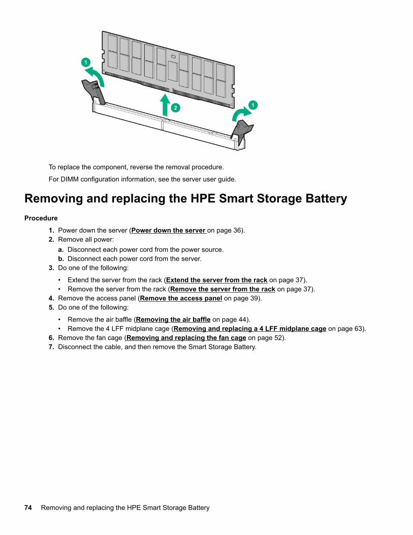
To replace the component, reverse the removal procedure.
For DIMM configuration information, see the server user guide.
Removing and replacing the HPE Smart Storage BatteryProcedure
1. Power down the server (Power down the server on page 36).2. Remove all power:
a. Disconnect each power cord from the power source.b. Disconnect each power cord from the server.
3. Do one of the following:
• Extend the server from the rack (Extend the server from the rack on page 37).• Remove the server from the rack (Remove the server from the rack on page 37).
4. Remove the access panel (Remove the access panel on page 39).5. Do one of the following:
• Remove the air baffle (Removing the air baffle on page 44).• Remove the 4 LFF midplane cage (Removing and replacing a 4 LFF midplane cage on page 63).
6. Remove the fan cage (Removing and replacing the fan cage on page 52).7. Disconnect the cable, and then remove the Smart Storage Battery.
74 Removing and replacing the HPE Smart Storage Battery
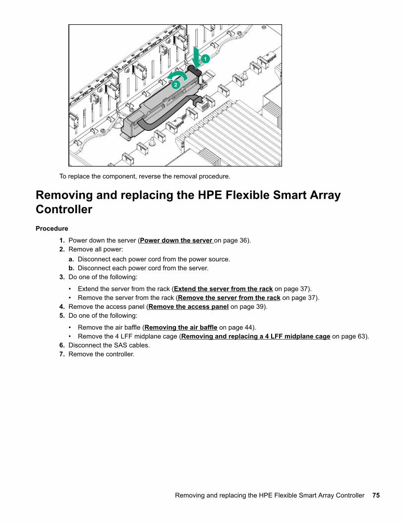
To replace the component, reverse the removal procedure.
Removing and replacing the HPE Flexible Smart ArrayControllerProcedure
1. Power down the server (Power down the server on page 36).2. Remove all power:
a. Disconnect each power cord from the power source.b. Disconnect each power cord from the server.
3. Do one of the following:
• Extend the server from the rack (Extend the server from the rack on page 37).• Remove the server from the rack (Remove the server from the rack on page 37).
4. Remove the access panel (Remove the access panel on page 39).5. Do one of the following:
• Remove the air baffle (Removing the air baffle on page 44).• Remove the 4 LFF midplane cage (Removing and replacing a 4 LFF midplane cage on page 63).
6. Disconnect the SAS cables.7. Remove the controller.
Removing and replacing the HPE Flexible Smart Array Controller 75

To replace the component, reverse the removal procedure.
Removing and replacing the system batteryThe system battery provides power to the real-time clock. If the server no longer automatically displays thecorrect date and time, you might need to replace the system battery.
WARNING:The computer contains an internal lithium manganese dioxide, a vanadium pentoxide, or an alkalinebattery pack. A risk of fire and burns exists if the battery pack is not properly handled. To reduce the riskof personal injury:
• Do not attempt to recharge the battery.• Do not expose the battery to temperatures higher than 60°C (140°F).• Do not disassemble, crush, puncture, short external contacts, or dispose of in fire or water.• Replace only with the spare designated for this product.
Procedure
1. Power down the server (Power down the server on page 36).2. Remove all power:
• Disconnect each power cord from the power source.• Disconnect each power cord from the server.
3. Do one of the following:
• Extend the server from the rack (Extend the server from the rack on page 37).• Remove the server from the rack (Remove the server from the rack on page 37.
4. Remove the access panel (Remove the access panel on page 39).5. If installed, remove the tertiary PCIe riser cage (Removing and replacing the tertiary PCIe riser cage on
page 46).6. Locate the battery (System board components on page 98).7. Remove the battery.
76 Removing and replacing the system battery

8. To replace the component, reverse the removal procedure.9. Properly dispose of the old battery.
For more information about battery replacement or proper disposal, contact an authorized reseller or anauthorized service provider.
Removing and replacing the system boardProcedure
Removing the system board1. Power down the server (Power down the server on page 36).2. Remove all power:
a. Disconnect each power cord from the power source.b. Disconnect each power cord from the server.
3. Remove the server from the rack (Remove the server from the rack on page 37).4. Remove all power supplies (Removing and replacing the AC power supply on page 43).5. Remove the access panel (Remove the access panel on page 39).6. Do one of the following:
• Remove the air baffle (Removing the air baffle on page 44).• Remove the 4 LFF midplane cage (Removing and replacing a 4 LFF midplane cage on page 63).
7. Remove the primary or secondary PCIe riser cage (Removing and replacing the primary orsecondary PCIe riser cages on page 45).
8. If installed, remove the tertiary PCIe riser cage (Removing and replacing the tertiary PCIe riser cageon page 46).
9. Remove the FlexibleLOM (Removing and replacing the FlexibleLOM on page 53).10. Remove all DIMMs (Removing and replacing a DIMM on page 73).11. Remove the fan cage (Removing and replacing the fan cage on page 52).12. Disconnect all cables connected to the system board.13. Observe the following cautions.
CAUTION:Be sure to loosen each screw in the order indicated. Otherwise, damage might occur to theheatsink or processor.
Removing and replacing the system board 77

CAUTION:Install the processor heatsink assembly as soon as possible after removing it. Do not leave theprocessor socket unpopulated for extended periods of time.
14. Remove the processor heatsink assembly:a. Allow the heatsink to cool.b. Using a T-30 Torx screwdriver, loosen the heatsink nuts.
c. Lift the processor heatsink assembly up and away from the system board.15. Loosen the system board thumbscrews.16. Remove the system board, using the handle to lift it out of the chassis.
Replacing the system board17. Install the spare system board.
18. Install the processor heatsink assembly:
78 Removal and replacement procedures

a. Locate the Pin 1 indicator on the processor frame and the socket.b. Align the processor heatsink assembly with the heatsink alignment pins and gently lower it down until
it sits evenly on the socket.The heatsink alignment pins are keyed. The processor heatsink assembly will only install one way.
Your heatsink may look different than the one shown.
c. Using a T-30 Torx screwdriver, fully tighten each heatsink nut until it no longer turns.
CAUTION:Be sure to tighten each screw fully in the order indicated. Otherwise, boot failure or intermittentshutdowns might occur.
Removal and replacement procedures 79

19. IMPORTANT:Install all components with the same configuration that was used on the failed system board.
Install all components removed from the failed system board.20. Install the access panel.21. Install the power supplies.22. Power up the server.23. Ensure all firmware, including option cards and embedded devices, is updated to the same versions to
ensure that the latest drivers are being used.24. Re-enter any Secure Boot Keys that were previously added in the Secure Boot configuration.25. Re-enter the server serial number and the product ID (Re-entering the server serial number and
product ID on page 80).
Re-entering the server serial number and product IDAfter you replace the system board, you must re-enter the server serial number and the product ID:
Procedure
1. During the server startup sequence, press the F9 key to access UEFI System Utilities.2. Select System Configuration > BIOS/Platform Configuration (RBSU) > Advanced Options >
Advanced System ROM Options > Serial Number, and then press the Enter key.3. Enter the serial number and press the Enter key.
The following message appears:
The serial number should only be modified by qualified service personnel. Thisvalue should always match the serial number located on the chassis.
4. To clear the warning, press the Enter key.5. Enter the serial number and press the Enter key.6. Select Product ID.
The following warning appears:
Warning: The Product ID should ONLY be modified by qualified servicepersonnel. This value should always match the Product ID located on thechassis.
7. Enter the product ID and press the Enter key.8. To confirm exiting System Utilities, press the F10 key.
The server automatically reboots.
HPE Trusted Platform Module 2.0 Gen10 OptionThe HPE Trusted Platform Module 2.0 Gen10 Option is not a customer-removable part.
CAUTION:If the TPM is removed from the original server and powered up on a different server, data stored in theTPM including keys will be erased.
If you suspect a TPM board failure, leave the TPM installed and remove the system board (Removing andreplacing the system board on page 77). Contact a Hewlett Packard Enterprise authorized service providerfor a replacement system board and TPM board.
80 Re-entering the server serial number and product ID

TroubleshootingTroubleshooting resources
Troubleshooting resources are available for HPE Gen10 server products in the following documents:
• Troubleshooting Guide for HPE ProLiant Gen10 servers provides procedures for resolving commonproblems and comprehensive courses of action for fault isolation and identification, issue resolution, andsoftware maintenance.
• Error Message Guide for HPE ProLiant Gen10 servers and HPE Synergy provides a list of error messagesand information to assist with interpreting and resolving error messages.
• Integrated Management Log Messages and Troubleshooting Guide for HPE ProLiant Gen 10 and HPESynergy provides IML messages and associated troubleshooting information to resolve critical andcautionary IML events.
To access the troubleshooting resources, see the Hewlett Packard Enterprise Information Library (http://www.hpe.com/info/gen10-troubleshooting).
Troubleshooting 81
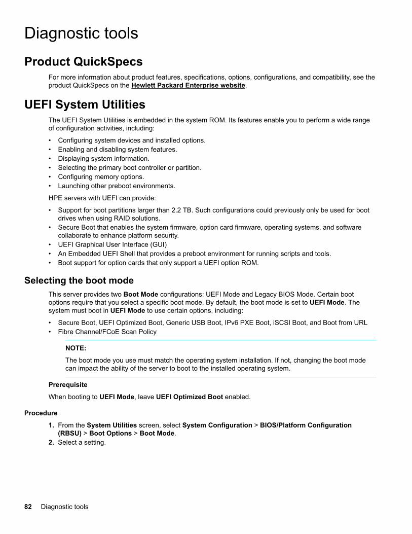
Diagnostic toolsProduct QuickSpecs
For more information about product features, specifications, options, configurations, and compatibility, see theproduct QuickSpecs on the Hewlett Packard Enterprise website.
UEFI System UtilitiesThe UEFI System Utilities is embedded in the system ROM. Its features enable you to perform a wide rangeof configuration activities, including:
• Configuring system devices and installed options.• Enabling and disabling system features.• Displaying system information.• Selecting the primary boot controller or partition.• Configuring memory options.• Launching other preboot environments.
HPE servers with UEFI can provide:
• Support for boot partitions larger than 2.2 TB. Such configurations could previously only be used for bootdrives when using RAID solutions.
• Secure Boot that enables the system firmware, option card firmware, operating systems, and softwarecollaborate to enhance platform security.
• UEFI Graphical User Interface (GUI)• An Embedded UEFI Shell that provides a preboot environment for running scripts and tools.• Boot support for option cards that only support a UEFI option ROM.
Selecting the boot modeThis server provides two Boot Mode configurations: UEFI Mode and Legacy BIOS Mode. Certain bootoptions require that you select a specific boot mode. By default, the boot mode is set to UEFI Mode. Thesystem must boot in UEFI Mode to use certain options, including:
• Secure Boot, UEFI Optimized Boot, Generic USB Boot, IPv6 PXE Boot, iSCSI Boot, and Boot from URL• Fibre Channel/FCoE Scan Policy
NOTE:
The boot mode you use must match the operating system installation. If not, changing the boot modecan impact the ability of the server to boot to the installed operating system.
Prerequisite
When booting to UEFI Mode, leave UEFI Optimized Boot enabled.
Procedure
1. From the System Utilities screen, select System Configuration > BIOS/Platform Configuration(RBSU) > Boot Options > Boot Mode.
2. Select a setting.
82 Diagnostic tools

• UEFI Mode (default)—Configures the system to boot to a UEFI compatible operating system.• Legacy BIOS Mode—Configures the system to boot to a traditional operating system in Legacy BIOS
compatibility mode.3. Save your setting.4. Reboot the server.
Secure BootSecure Boot is a server security feature that is implemented in the BIOS and does not require specialhardware. Secure Boot ensures that each component launched during the boot process is digitally signed andthat the signature is validated against a set of trusted certificates embedded in the UEFI BIOS. Secure Bootvalidates the software identity of the following components in the boot process:
• UEFI drivers loaded from PCIe cards• UEFI drivers loaded from mass storage devices• Preboot UEFI Shell applications• OS UEFI boot loaders
When Secure Boot is enabled:
• Firmware components and operating systems with boot loaders must have an appropriate digital signatureto execute during the boot process.
• Operating systems must support Secure Boot and have an EFI boot loader signed with one of theauthorized keys to boot. For more information about supported operating systems, see the UEFI SystemUtilities and Shell Release Notes for Gen10 and HPE Synergy on the Hewlett Packard Enterprise website(http://www.hpe.com/info/ProLiantUEFI/docs.).
You can customize the certificates embedded in the UEFI BIOS by adding or removing your own certificates,either from a management console directly attached to the server, or by remotely connecting to the serverusing the iLO Remote Console.
You can configure Secure Boot:
• Using the System Utilities options described in the following sections.• Using the RESTful API to clear and restore certificates. For more information, see the Hewlett Packard
Enterprise website (www.hpe.com/support/restfulinterface/docs).• Using the secboot command in the Embedded UEFI Shell to display Secure Boot databases, keys, and
security reports.
Launching the Embedded UEFI ShellUse the Embedded UEFI Shell option to launch the Embedded UEFI Shell. The Embedded UEFI Shell is apre-boot command-line environment for scripting and running UEFI applications, including UEFI boot loaders.The Shell also provides CLI-based commands you can use to obtain system information, and to configure andupdate the system BIOS.
Prerequisites
• Embedded UEFI Shell is set to enabled.
Procedure
1. From the System Utilities screen, select Embedded Applications > Embedded UEFI Shell.
The Embedded UEFI Shell screen appears.2. Press any key to acknowledge that you are physically present.
This step ensures that certain features, such as disabling Secure Boot or managing the Secure Bootcertificates using third-party UEFI tools, are not restricted.
3. If an administrator password is set, enter it at the prompt and press Enter.
Secure Boot 83

The Shell> prompt appears.4. Enter the commands required to complete your task.5. Enter the exit command to exit the Shell.
Intelligent ProvisioningIntelligent Provisioning is a single-server deployment tool embedded in ProLiant servers, Apollo systems, andHPE Synergy compute modules. Intelligent Provisioning simplifies server setup, providing a reliable andconsistent way to deploy servers.
Intelligent Provisioning prepares the system for installing original, licensed vendor media and Hewlett PackardEnterprise-branded versions of OS software. Intelligent Provisioning also prepares the system to integrateoptimized server support software from the Service Pack for ProLiant (SPP). SPP is a comprehensivesystems software and firmware solution for ProLiant servers, server blades, their enclosures, and HPESynergy compute modules. These components are preloaded with a basic set of firmware and OScomponents that are installed along with Intelligent Provisioning.
After the server is running, you can update the firmware to install additional components. You can also updateany components that have been outdated since the server was manufactured.
Intelligent Provisioning operationIntelligent Provisioning includes the following components:
• Critical boot drivers• Active Health System (AHS)• Erase Utility• Deployment Settings
IMPORTANT:
• Although your server is pre-loaded with firmware and drivers, you should update the firmware uponinitial setup to ensure you have the latest versions. Also, downloading and updating the latestversion of Intelligent Provisioning ensures the latest supported features are available.
• For ProLiant servers, firmware is updated using the Intelligent Provisioning Firmware Update utility.• Do not update firmware if the version you are currently running is required for compatibility.
NOTE:
Intelligent Provisioning does not function within multihomed configurations. A multihomed host is onethat is connected to two or more networks or has two or more IP addresses.
Intelligent Provisioning provides installation help for the following operating systems:
• Microsoft Windows Server• Red Hat Enterprise Linux• SUSE Linux Enterprise Server• VMware ESXi/vSphere Custom Image
Not all versions of an OS are supported. For information about specific versions of a supported operatingsystem, see the OS Support Matrix on the Hewlett Packard Enterprise website (http://www.hpe.com/info/ossupport).
HPE Insight Remote SupportHewlett Packard Enterprise strongly recommends that you register your device for remote support to enableenhanced delivery of your Hewlett Packard Enterprise warranty, HPE support services, or Hewlett PackardEnterprise contractual support agreement. Insight Remote Support supplements your monitoring continuously
84 Intelligent Provisioning

to ensure maximum system availability by providing intelligent event diagnosis, and automatic, securesubmission of hardware event notifications to Hewlett Packard Enterprise, which will initiate a fast andaccurate resolution, based on your product’s service level. Notifications can be sent to your authorizedHewlett Packard Enterprise Channel Partner for onsite service, if configured and available in your country.
For more information, see Insight Remote Support and Insight Online Setup Guide for ProLiant Servers andBladeSystem c-Class Enclosures on the Hewlett Packard Enterprise website. Insight Remote Support isavailable as part of Hewlett Packard Enterprise Warranty, HPE support services, or Hewlett PackardEnterprise contractual support agreement.
USB supportHewlett Packard Enterprise servers support both USB 2.0 ports and USB 3.0 ports. Both port types supportinstalling all types of USB devices (USB 1.0, USB 2.0, and USB 3.0), but might run at lower speeds in specificsituations:
• USB 3.0 capable devices operate at USB 2.0 speeds when installed in a USB 2.0 port.• In UEFI Boot Mode, Hewlett Packard Enterprise provides legacy USB support in the preboot environment
before the operating system loading for USB 1.0, USB 2.0, and USB 3.0 speeds.• In Legacy BIOS Boot Mode, Hewlett Packard Enterprise provides legacy USB support in the preboot
environment before the operating system loading for USB 1.0 and USB 2.0 speeds. USB 3.0 ports can beused with all devices in Legacy BIOS Boot Mode but are not available at USB 3.0 speeds in the prebootenvironment. Standard USB support (USB support from within the operating system) is provided by theOS through the appropriate USB device drivers. Support for USB 3.0 varies by operating system.
For maximum compatibility of USB 3.0 devices with all operating systems, Hewlett Packard Enterpriseprovides a configuration setting for USB 3.0 Mode. Auto is the default setting. This setting impacts USB 3.0devices when connected to USB 3.0 ports in the following manner:
• Auto (default)—If configured in Auto Mode, USB 3.0 capable devices operate at USB 2.0 speeds in thepreboot environment and during boot. When a USB 3.0 capable OS USB driver loads, USB 3.0 devicestransition to USB 3.0 speeds. This mode is compatible with operating systems that do not support USB 3.0while allowing USB 3.0 devices to operate at USB 3.0 speeds with state-of-the-art operating systems.
• Enabled—If Enabled, USB 3.0 capable devices operate at USB 3.0 speeds at all times (including thepreboot environment) when in UEFI Boot Mode. Do not use this mode with operating systems that do notsupport USB 3.0. If operating in Legacy Boot BIOS Mode, the USB 3.0 ports cannot function in the prebootenvironment and are not bootable.
• Disabled—If configured for Disabled, USB 3.0 capable devices function at USB 2.0 speeds at all times.
The pre-OS behavior and default operation of the USB ports is configurable in the UEFI System Utilities. Formore information, see the UEFI System Utilities user guide for your product on the Hewlett PackardEnterprise website.
External USB functionalityHewlett Packard Enterprise provides external USB support to enable local connection of USB devices forserver administration, configuration, and diagnostic procedures.
For additional security, external USB functionality can be disabled through USB options in UEFI SystemUtilities.
HPE Smart Storage AdministratorHPE SSA is the main tool for configuring arrays on HPE Smart Array SR controllers. It exists in three interfaceformats: the HPE SSA GUI, the HPE SSA CLI, and HPE SSA Scripting. All formats provide support forconfiguration tasks. Some of the advanced tasks are available in only one format.
The diagnostic features in HPE SSA are also available in the standalone software HPE Smart StorageAdministrator Diagnostics Utility CLI.
USB support 85

HPE SSA is accessible both offline (either through HPE Intelligent Provisioning or as a standalone bootableISO image) and online:
• Accessing HPE SSA in the offline environment
IMPORTANT:If you are updating an existing server in an offline environment, obtain the latest version of HPE SSAthrough Service Pack for ProLiant before performing configuration procedures.
Using one of multiple methods, you can run HPE SSA before launching the host operating system. Inoffline mode, users can configure or maintain detected and supported devices, such as optional SmartArray controllers and integrated Smart Array controllers. Some HPE SSA features are only available in theoffline environment, such as setting the boot controller and boot volume.
• Accessing HPE SSA in the online environment
This method requires an administrator to download the HPE SSA executables and install them. You canrun HPE SSA online after launching the host operating system.
For more information, see HPE Smart Array SR Gen10 Configuration Guide at the Hewlett PackardEnterprise website.
86 Diagnostic tools

Component identificationFront panel componentsSFF front panel components
Item Description
1 Box 1 (optional drives or universal media bay)
2 Box 2 (optional drives)
3 Box 3 Drives 1-8
4 Serial label pull tab or optional Systems Insight Display
5 iLO service port
6 USB 3.0 port
Universal media bay components
Item Description
1 USB 2.0 port
2 Video display port
3 Optical disk drive (optional)
4 Drives (optional)
Component identification 87

12-drive LFF front panel components
Item Description
1 Drive bays
8-drive LFF model front panel components
Item Description
1 Drives (optional)
2 LFF power switch module
3 Drive bays
LFF power switch module components
88 Component identification

Item Description
1 Optical disk drive
2 Serial label pull tab
3 USB 3.0 port
4 iLO service port
5 Video display port
Front panel LEDs and buttonsSFF front panel LEDs and button
Item Description Status
1 Power On/Standby button andsystem power LED*
Solid green = System on
Flashing green (1 Hz/cycle per sec) = Performingpower on sequence
Solid amber = System in standby
Off = No power present†
2 Health LED* Solid green = Normal
Flashing green (1 Hz/cycle per sec) = iLO is rebooting
Flashing amber = System degraded
Flashing red (1 Hz/cycle per sec) = System critical**
Table Continued
Front panel LEDs and buttons 89

Item Description Status
3 NIC status LED* Solid green = Link to network
Flashing green (1 Hz/cycle per sec) = Network active
Off = No network activity
4 UID button/LED* Solid blue = Activated
Flashing blue:
• 1 Hz/cycle per sec = Remote management orfirmware upgrade in progress
• 4 Hz/cycle per sec = iLO manual reboot sequenceinitiated
• 8 Hz/cycle per sec = iLO manual reboot sequencein progress
Off = Deactivated
*When all four LEDs described in this table flash simultaneously, a power fault has occurred. For moreinformation, see "Power fault LEDs."
**If the health LED indicates a degraded or critical state, review the system IML or use iLO to review thesystem health status.
†Facility power is not present, power cord is not attached, no power supplies are installed, power supplyfailure has occurred, or the power button cable is disconnected.
LFF 12-drive model front panel LEDs and button
90 Component identification

Item Description Status
1 Health LED* Solid green = Normal
Flashing green (1 Hz/cycle per sec) = iLO is rebooting
Flashing amber = System degraded
Flashing red (1 Hz/cycle per sec) = System critical**
2 Power On/Standby button andsystem power LED*
Solid green = System on
Flashing green (1 Hz/cycle per sec) = Performingpower on sequence
Solid amber = System in standby
Off = No power present†
3 NIC status LED* Solid green = Link to network
Flashing green (1 Hz/cycle per sec) = Network active
Off = No network activity
4 UID button/LED* Solid blue = Activated
Flashing blue:
• 1 Hz/cycle per sec = Remote management orfirmware upgrade in progress
• 4 Hz/cycle per sec = iLO manual reboot sequenceinitiated
• 8 Hz/cycle per sec = iLO manual reboot sequencein progress
Off = Deactivated
*When all four LEDs described in this table flash simultaneously, a power fault has occurred. For moreinformation, see "Power fault LEDs."
**If the health LED indicates a degraded or critical state, review the system IML or use iLO to review thesystem health status.
†Facility power is not present, power cord is not attached, no power supplies are installed, power supplyfailure has occurred, or the power button cable is disconnected.
Component identification 91

LFF power switch module LEDs and button
Item Description Status
1 UID button/LED* Solid blue = Activated
Flashing blue:
• 1 Hz/cycle per sec = Remote management orfirmware upgrade in progress
• 4 Hz/cycle per sec = iLO manual reboot sequenceinitiated
• 8 Hz/cycle per sec = iLO manual reboot sequencein progress
Off = Deactivated
2 Health LED* Solid green = Normal
Flashing green (1 Hz/cycle per sec) = iLO is rebooting
Flashing amber = System degraded
Flashing red (1 Hz/cycle per sec) = System critical**
3 NIC status LED* Solid green = Link to network
Flashing green (1 Hz/cycle per sec) = Network active
Off = No network activity
4 Power On/Standby button andsystem power LED*
Solid green = System on
Flashing green (1 Hz/cycle per sec) = Performingpower on sequence
Solid amber = System in standby
Off = No power present†
*When all four LEDs described in this table flash simultaneously, a power fault has occurred. For moreinformation, see "Power fault LEDs."
92 Component identification

**If the health LED indicates a degraded or critical state, review the system IML or use iLO to review thesystem health status.
†Facility power is not present, power cord is not attached, no power supplies are installed, power supplyfailure has occurred, or the power button cable is disconnected.
UID button functionalityThe UID button can be used to display the HPE ProLiant Pre-boot Health Summary when the server will notpower on. For more information, see the latest HPE iLO User Guide on the Hewlett Packard Enterprisewebsite.
Power fault LEDsThe following table provides a list of power fault LEDs, and the subsystems that are affected. Not all powerfaults are used by all servers.
Subsystem LED behavior
System board 1 flash
Processor 2 flashes
Memory 3 flashes
Riser board PCIe slots 4 flashes
FlexibleLOM 5 flashes
Removable HPE Flexible Smart Arraycontroller/Smart SAS HBA controller
6 flashes
System board PCIe slots 7 flashes
Power backplane or storage backplane 8 flashes
Power supply 9 flashes
Systems Insight Display LEDsThe Systems Insight Display LEDs represent the system board layout. The display enables diagnosis with theaccess panel installed.
UID button functionality 93

Description Status
Processor LEDs Off = Normal
Amber = Failed processor
DIMM LEDs Off = Normal
Amber = Failed DIMM or configuration issue
Fan LEDs Off = Normal
Amber = Failed fan or missing fan
NIC LEDs Off = No link to network
Solid green = Network link
Flashing green = Network link with activity
If power is off, the front panel LED is not active. Forstatus, see Rear panel LEDs on page 97.
Power supply LEDs Off = Normal
Solid amber = Power subsystem degraded, powersupply failure, or input power lost.
PCI riser LED Off = Normal
Amber = Incorrectly installed PCI riser cage
Over temp LED Off = Normal
Amber = High system temperature detected
Amp Status LED Off = AMP modes disabled
Solid green = AMP mode enabled
Solid amber = Failover
Flashing amber = Invalid configuration
Power cap LED Off = System is in standby, or no cap is set.
Solid green = Power cap applied
When the health LED on the front panel illuminates either amber or red, the server is experiencing a healthevent. For more information on the combination of these LEDs, see Systems Insight Display combinedLED descriptions on page 94).
Systems Insight Display combined LED descriptionsThe combined illumination of the following LEDs indicates a system condition:
• Systems Insight Display LEDs• System power LED• Health LED
94 Systems Insight Display combined LED descriptions

Systems Insight DisplayLED and color
HealthLED
Systempower LED
Status
Processor (amber) Red Amber One or more of the followingconditions may exist:
• Processor in socket X has failed.• Processor X is not installed in the
socket.• Processor X is unsupported.• ROM detects a failed processor
during POST.
Processor (amber) Amber Green Processor in socket X is in a pre-failure condition.
DIMM (amber) Red Green One or more DIMMs have failed.
DIMM (amber) Amber Green DIMM in slot X is in a pre-failurecondition.
Over temp (amber) Amber Green The Health Driver has detected acautionary temperature level.
Over temp (amber) Red Amber The server has detected a hardwarecritical temperature level.
PCI riser (amber) Red Green The PCI riser cage is not seatedproperly.
Fan (amber) Amber Green One fan has failed or has beenremoved.
Fan (amber) Red Green Two or more fans have failed or beenremoved.
Power supply (amber) Red Amber One or more of the followingconditions may exist:
• Only one power supply is installedand that power supply is instandby.
• Power supply fault• System board fault
Power supply (amber) Amber Green One or more of the followingconditions may exist:
• Redundant power supply isinstalled and only one powersupply is functional.
• AC power cord is not plugged intoredundant power supply.
• Redundant power supply fault• Power supply mismatch at POST
or power supply mismatch throughhot-plug addition
Table Continued
Component identification 95

Systems Insight DisplayLED and color
HealthLED
Systempower LED
Status
Power cap (off) — Amber Standby
Power cap (green) — Flashinggreen
Waiting for power
Power cap (green) — Green Power is available.
Power cap (flashing amber) — Amber Power is not available.
IMPORTANT:If more than one DIMM slot LED is illuminated, further troubleshooting is required. Test each bank ofDIMMs by removing all other DIMMs. Isolate the failed DIMM by replacing each DIMM in a bank with aknown working DIMM.
Rear panel components
Item Description
1 Primary riser slots 1-3 (Optional drive cage)
2 Optional riser slots 4-6 (Optional drive cage)
3 Optional riser slots 7-8 (Optional drive cage)
4 Power supply 1
5 Power supply 2
6 Video port
7 Serial port (optional)*
8 1Gb RJ-45 ports 1–4
9 iLO management port
10 USB 3.0 ports
11 FlexibleLOM slot
*When a tertiary riser cage is installed as shown, the serial port can installed in riser slot 6.
96 Rear panel components

Rear panel LEDs
Item Description Status
1 UID LED Off = Deactivated
Solid blue = Activated
Flashing blue = System beingmanaged remotely
2 Link LED Off = No network link
Green = Network link
3 Activity LED Off = No network activity
Solid green = Link to network
Flashing green = Network activity
4 Power supplyLEDs
Off = System is off or power supply hasfailed.
Solid green = Normal
Rear panel LEDs 97

System board components
Item Description
1 FlexibleLOM connector
2 System maintenance switch
3 Primary PCIe riser connector
4 Front display port/USB 2.0 connector
Table Continued
98 System board components

Item Description
5 x4 SATA port 1
6 x4 SATA port 2
7 x2 SATA port 3
8 x1 SATA port 4
9 Optical disk drive/SATA port 5
10 Front power/USB 3.0 connector
11 Drive backplane power connectors
12 Smart Storage Battery connector
13 Chassis intrusion detection connector
14 Drive backplane power connector
15 Micro SD card slot
16 Dual internal USB 3.0 ports
17 Type-a Smart Array connector
18 Secondary PCIe riser connector*
19 System battery
20 Tertiary PCIe riser connector*
21 TPM connector
22 Serial port connector (optional)
* Requires a second processor
System maintenance switch descriptionsPosition Default Function
S1 1 Off Off = iLO security is enabled.
On = iLO security is disabled.
S2 — Reserved
S3 Off Reserved
S4 Off Reserved
S51 Off Off = Power-on password isenabled.
On = Power-on password isdisabled.
S61, 2 Off Off = No function
On = Restore defaultmanufacturing settings
Table Continued
System maintenance switch descriptions 99

Position Default Function
S7 — Reserved
S8 — Reserved
S9 — Reserved
S10 — Reserved
S11 — Reserved
S12 — Reserved
1You can access the redundant ROM by setting S1, S5, and S6 to On.2When the system maintenance switch position 6 is set to the On position, the system is prepared to restoreall configuration settings to their manufacturing defaults.
When the system maintenance switch position 6 is set to the On position and Secure Boot is enabled, someconfigurations cannot be restored. For more information, see Secure Boot configuration.
Processor, heatsink, and socket components
Item Description
1 Heatsink nuts
2 Processor frame
3 Pin 1 indicator1
4 Heatsink latch
5 Alignment post
1 Symbol also on the processor and frame.
Drives
100 Processor, heatsink, and socket components

SAS/SATA drive components and LEDs
Item Description Status
1 Locate • Solid blue = The drive is being identified by a hostapplication.
• Flashing blue = The drive carrier firmware is beingupdated or requires an update.
2 Activity ring LED • Rotating green = Drive activity.• Off = No drive activity.
3 Do not remove LED • Solid white = Do not remove the drive. Removingthe drive causes one or more of the logical drives tofail.
• Off = Removing the drive does not cause a logicaldrive to fail.
4 Drive status LED • Solid green = The drive is a member of one or morelogical drives.
• Flashing green = The drive is rebuilding orperforming a RAID migration, strip size migration,capacity expansion, or logical drive extension, or iserasing.
• Flashing amber/green = The drive is a member ofone or more logical drives and predicts the drive willfail.
• Flashing amber = The drive is not configured andpredicts the drive will fail.
• Solid amber = The drive has failed.• Off = The drive is not configured by a RAID
controller.
SAS/SATA drive components and LEDs 101

NVMe drive components and LEDs
Item Description
1 Release lever
2 Activity ring
3 Do Not Remove LED1
4 Request to Remove NVMe Drive button
1Do not remove an NVMe SSD from the drive bay while the Do Not Remove button LED is flashing. The DoNot Remove button LED flashes to indicate the device is still in use. Removal of the NVMe SSD before thedevice has completed and ceased signal/traffic flow can cause loss of data.
uFF drive components and LEDs
Item Description Status
1 Locate • Off—Normal• Solid blue—The drive is being identified by a host
application• Flashing blue—The drive firmware is being updated
or requires an update
2 uFF drive ejection latch Removes the uFF drive when released
Table Continued
102 NVMe drive components and LEDs

Item Description Status
3 Do not remove LED • Off—OK to remove the drive. Removing the drivedoes not cause a logical drive to fail.
• Solid white—Do not remove the drive. Removingthe drive causes one or more of the logical drives tofail.
4 Drive status LED • Off—The drive is not configured by a RAIDcontroller
• Solid green—The drive is a member of one or morelogical drives
• Flashing green (4 Hz)—The drive is operatingnormally and has activity
• Flashing green (1 Hz)—The drive is rebuilding orperforming a RAID migration, stripe size migration,capacity expansion, logical drive extension, or iserasing
• Flashing amber/green (1 Hz)—The drive is amember of one or more logical drives that predictsthe drive will fail
• Solid amber—The drive has failed• Flashing amber (1 Hz)—The drive is not configured
and predicts the drive will fail
5 Adapter ejection release latchand handle
Removes the SFF flash adapter when released
Fan bay numbering
Fan bay numbering 103

Drive box identificationFront boxes
Item Description
1 Box 1
2 Box 2
3 Box 3
Item Description
1 Box 1
2 Box 2
3 Box 3
Rear boxes
Item Description
1 Box 4
2 Box 5
3 Box 6
104 Drive box identification
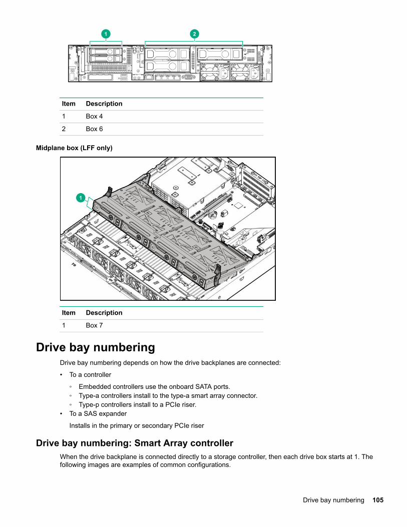
Item Description
1 Box 4
2 Box 6
Midplane box (LFF only)
Item Description
1 Box 7
Drive bay numberingDrive bay numbering depends on how the drive backplanes are connected:
• To a controller
◦ Embedded controllers use the onboard SATA ports.◦ Type-a controllers install to the type-a smart array connector.◦ Type-p controllers install to a PCIe riser.
• To a SAS expander
Installs in the primary or secondary PCIe riser
Drive bay numbering: Smart Array controllerWhen the drive backplane is connected directly to a storage controller, then each drive box starts at 1. Thefollowing images are examples of common configurations.
Drive bay numbering 105

106 Component identification

Drive bay numbering: SAS expanderDrive numbering through a SAS Expander is continuous.
• SAS expander port 1 always connects to port 1 of the controller.• SAS expander port 2 always connects to port 2 of the controller.• SAS expander port 3 = drive numbers 1-4.• SAS expander port 4 = drive numbers 5-8.• SAS expander port 5 = drive numbers 9-12.• SAS expander port 6 = drive numbers 13-16.• SAS expander port 7 = drive numbers 17-20.• SAS expander port 8 = drive numbers 21-24.• SAS expander port 9 = drive numbers 25-28.
Common configuration examples:
Drive bay numbering: SAS expander 107

When any stacked 2SFF drive cage is connected to the SAS expander, the drive numbering skips the secondnumber to allow uFF drive bay numbering on page 110. For example, when a rear 2SFF drive cage isconnected to SAS expander port 9, then the drive numbers are 25 and 27.
When the front 24SFF bays are populated, any installed rear 2SFF drives are always 25 and 27.
If a 2SFF drive cage is connected to SAS expander port 3, then the drive numbers are 1 and 3.
108 Component identification

Front 12LFF + Midplane 4LFF + All rear 2SFF:
Drive bay numbering: NVMe drivesIf the server is populated with NVMe drives and NVMe risers:
Drive bay numbering: NVMe drives 109

uFF drive bay numberingThere are two uFF drives in each drive carrier.
If the drives are connected to a controller:
• The left bay = The default bay number of the server• The right bay = The default bay number of the server + 100
If the drives are connected to a SAS expander:
For example:
• If the drives are connected to port 3 of the SAS expander, then the uFF drives are 1-4.• If the drives are connected to port 9 of the SAS expander, then the uFF drives are 25-28.
110 uFF drive bay numbering

Cabling
HPE ProLiant Gen10 DL Servers Storage Cabling GuidelinesWhen installing cables, observe the following:
• All ports are labeled:
◦ System board ports◦ Controller ports◦ 12G SAS Expander ports
• Most data cables have labels near each connector with destination port information.• Some data cables are pre-bent. Do not unbend or manipulate the cables.• Before connecting a cable to a port, lay the cable in place to verify the length of the cable.• When routing cables from the front to the rear of the server, use the cable channels on either side of the
chassis.
Cabling diagramsUse the following tables to find cabling information and diagrams. For additional cabling configurations, seethe HPE Information Library (http://www.hpe.com/info/CablingMatrixGen10).
Table 1: SAS/SATA kits
Option kit Cable partnumber*
From To Power cable partnumber
Front 2SFF SAS/SATA drive cage(SFF)
869826-001 1 Drivebackplane
System board
SAS Expander
Controller
869810-001 6
869825-001 6
Front 2SFF SAS/SATA 1U drivecage (LFF)
869826-001 1 Drivebackplane
System board
SAS Expander
Controller
869810-001 6
Front 8SFF SAS/SATA drive cages 776402-001 4 Drivebackplane
System board
SAS Expander
Controller
869825-001 6
Front 4LFF SAS/SATA drive cages 869827-001 1 Drivebackplane
System board
SAS Expander
Controller
869825-001 6
Mid 4LFF SAS/SATA drive cage 869824-001 2 Drivebackplane
System board
SAS Expander
Controller
869810-001 6
Table Continued
Cabling 111

Option kit Cable partnumber*
From To Power cable partnumber
Rear 2SFF SAS/SATA riser drivecage
869823-001 3 Drivebackplane
System board
SAS Expander
Controller
869806-001 6
Rear 3LFF SAS/SATA drive cage 869823-001 3 Drivebackplane
System board
SAS Expander
Controller
869810-001 6
12G SAS Expander card 869802-001 5
869803-001 5SAS Expander Controller -
SAS/SATA 3-position cable 869830-001 3
869816-001 3Drivebackplane
System board -
* To order spare cables, use the following kits and spare part numbers.1 Mini-SAS LFF Kit (875090-001)2 12G SAS Expander Kit (875094-001)3 Mini-SAS SFF Kit (875089-001)4 SAS 8SFF Kit (784629-001)5 12G SAS Expander to controller kit (875093-001)6 Power cables kit (875096-001)
Table 2: NVMe bay/riser kits
Option kit Cable partnumber
From To Power cable partnumber
Front 2SFF NVMe drive cage NVMe cableincluded withNVMe riser
Drivebackplane
Tertiary riser 869810-001 3
Front 8SFF SAS/SATA/NVMePremium for SFF
776402-001
NVMe cableincluded withNVMe riser
Drivebackplane
SATA toSystemboard,controller, orSAS expander
Tertiary riser
869825-001 3
Front 8SFF NVMe drive cage NVMe cableincluded withNVMe riser
Drivebackplane
Primary riser 869825-001 3
HPE DL380 Gen10 4-Port SlimSAS Riser, Secondary PCIe
869814-001 1
869813-001 1PCIe riser Backplane -
Table Continued
112 Cabling

Option kit Cable partnumber
From To Power cable partnumber
HPE DL380 Gen10 2-Port SlimSAS Riser, Tertiary PCIe
869812-001 1
869812-001 1PCIe riser Backplane -
HPE DL380 Gen10 4-Port SlimSAS Riser
869811-001
776402-001
PCIe riser Backplane -
HPE DL380 Gen10 1-Port SlimSAS Riser
869812-001 1 PCIe riser Backplane -
1 NVMe Direct Attach Kit (875092-001)2 NVMe SFF Riser Kit (875091-001)3 Power cables kit (875096-001)
Table 3: GPU power
Option kit Cable partnumber
From To
HPE GPU 6px6p Y-Power CableKit
873193-001 1 GPU Riser
HPE GPU 8px6p Y-Power CableKit
869805-001 1 GPU Riser
HPE GPU 8p Keyed GPU CableKit
869820-001 1 GPU Riser
HPE GPU 8p Cable Kit 869821-001 1 GPU Riser
HPE GPU power adapter 869828-001 1 GPU System board
1 GPU cables kit (875097-001)
Table 4: Data kits
Option kit Cable partnumber
From To
Front USB/display port (SFF UMB) 869804-001 1 Component System board
Front USB port (SFF UMB) 869829-001 1 Component System board
Front display port (LFF) 869808-001 1 Component System board
Optical disk drive 756914-001 2 Component System board
Systems Insight Display Included withcomponent
Component System board
1 Data cables kit (875095-001)2 DVD cable kit (784623-001)
Cable routing: Front 2SFF drive option for SFFOption 1: System board
Cable routing: Front 2SFF drive option for SFF 113

Option 2: SAS Expander
Option 3 (not shown): A controller
Cable routing: Front 2SFF drive option for LFFOption 1: System board
114 Cable routing: Front 2SFF drive option for LFF

Option 2: Controller
Option 3 (not shown): SAS Expander
Cable routing: Front 2SFF drive options (3 position cable)SFF models
Cable routing: Front 2SFF drive options (3 position cable) 115

LFF models
Cable routing: Front 8SFF drive optionsBox 1 to SAS Expander
116 Cable routing: Front 8SFF drive options
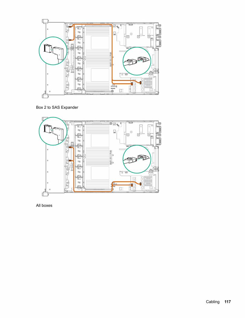
Box 2 to SAS Expander
All boxes
Cabling 117

Cable routing: Front 8SFF NVMe/SAS premium drive optionThe backplane shown is in box 3.
Cable routing: Front 8SFF NVMe drive optionsBox 1
118 Cable routing: Front 8SFF NVMe/SAS premium drive option

Box 2
Box 3
Cabling 119

Cable routing: Front 2SFF NVMe drive option for SFF
120 Cable routing: Front 2SFF NVMe drive option for SFF

Cable routing: Front 2SFF NVMe drive option for LFF
Cable routing: Midplane 4LFF drive option
Cable routing: Front 2SFF NVMe drive option for LFF 121
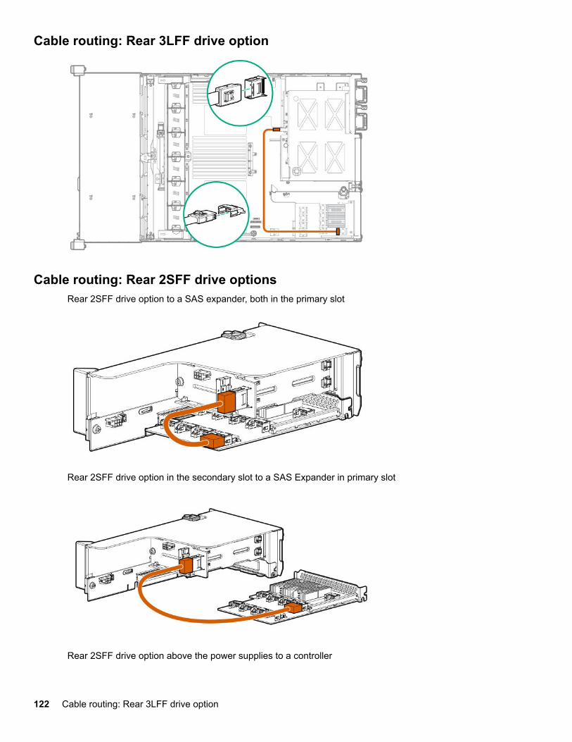
Cable routing: Rear 3LFF drive option
Cable routing: Rear 2SFF drive optionsRear 2SFF drive option to a SAS expander, both in the primary slot
Rear 2SFF drive option in the secondary slot to a SAS Expander in primary slot
Rear 2SFF drive option above the power supplies to a controller
122 Cable routing: Rear 3LFF drive option

Cable routing: HPE 12G SAS Expander to a controllerObserve the following:
• Port 1 always connects to port 1 of the controller.• Port 2 always connects to port 2 of the controller.
SAS expander to an a-type controller
SAS expander to a p-type controller
Cable routing: HPE 12G SAS Expander to a controller 123

Cable routing: Systems Insight DisplayAn SFF model is shown. The routing is the same for LFF.
124 Cable routing: Systems Insight Display

SpecificationsEnvironmental specifications
Specification Value
Temperature range 1 —
Operating 10°C to 35°C (50°F to 95°F)
Nonoperating -30°C to 60°C (-22°F to 140°F)
Relative humidity (noncondensing) —
Operating Minimum to be the higher (more moisture) of -12°C(10.4°F) dew point or 8% relative humidity
Maximum to be 24°C (75.2°F) dew point or 90%relative humidity
Nonoperating 5% to 95%
38.7°C (101.7°F), maximum wet bulb temperature
1 All temperature ratings shown are for sea level. An altitude derating of 1.0°C per 304.8 m (1.8°F per 1000 ft)to 3048 m (10,000 ft) is applicable. No direct sunlight allowed. Maximum rate of change is 20°C per hour(36°F per hour). The upper limit and rate of change might be limited by the type and number of optionsinstalled.
For certain approved hardware configurations, the supported system inlet temperature range is extended:
• 5°C to 10°C (41°F to 50°F) and 35°C to 40°C (95°F to 104°F) at sea level with an altitude derating of 1.0°Cper every 175 m (1.8°F per every 574 ft) above 900 m (2953 ft) to a maximum of 3048 m (10,000 ft).
• 40°C to 45°C (104°F to 113°F) at sea level with an altitude derating of 1.0°C per every 125 m (1.8°F perevery 410 ft) above 900 m (2953 ft) to a maximum of 3048 m (10,000 ft).
The approved hardware configurations for this system are listed on the Hewlett Packard Enterprisewebsite.
Mechanical specificationsSpecification Value
Height 8.73 cm (3.44 in)
Depth, SFF 67.94 cm (26.75 in)
Depth, LFF 73.02 cm (28.75 in)
Width 44.54 cm (17.54 in)
Weight, SFF minimum 14.9 kg (32.75 lbs)
Weight, SFF maximum 19.5kg (43.00 lbs)
Weight, LFF minimum 17.1 kg (37.75 lbs)
Weight, LFF maximum 24.5 kg (54 lbs)
The SFF configuration includes the following components:
Specifications 125

• SFF drive (1)• Drive blanks (7)• Drive bay blanks for bays 1 and 2 (2)• Fan assemblies (4)• Fan blanks (2)• Standard heatsink (1)• 1P air baffle (1)• X8 HPE Flexible Smart Array Controller (1)• Primary riser cage (1)• Secondary riser cage blank (1)• Power supply (1)• Power supply blank (1)• Cables for the above components
The LFF configuration includes the following components:
• LFF drives (12)• Fan assemblies (6)• SE heatsinks (2)• 2P air baffle (1)• X8 HPE Flexible Smart Array Controller (1)• Primary riser cage (1)• Secondary riser cage (1)• Power supplies (2)• Cables for the above components
The 12 LFF configuration does not contain a rear three-bay LFF drive cage option.
Power supply specificationsDepending on the installed options, the server can be configured with one of the following power supplies:
• HPE 500W Flex Slot Platinum Hot-plug Power Supply• HPE 800W Flex Slot Platinum Hot-plug Power Supply• HPE 800W Flex Slot Titanium Plus Hot-plug Power Supply• HPE 800W Flex Slot Universal Hot-plug Power Supply• HPE 800W Flex Slot -48VDC Hot-plug Power Supply• HPE 1600W Flex Slot Platinum Plus Hot-plug Power Supply
For detailed power supply specifications, see the QuickSpecs on the Hewlett Packard Enterprise website.
HPE 500W Flex Slot Platinum Hot-plug Power SupplySpecification Value
Input requirements
Rated input voltage 100 to 127 VAC
200 to 240 VAC
240 VDC for China only
Table Continued
126 Power supply specifications

Rated input frequency 50 Hz to 60 Hz
Not applicable to 240 VDC
Rated input current 5.8 A at 100 VAC
2.8 A at 200 VAC
2.4 A at 240 VDC for Chinaonly
Maximum rated input power 580 W at 100 VAC
560 W at 200 VAC
576 W at 240 VDC for Chinaonly
BTUs per hour 1979 at 100 VAC
1911 at 200 VAC
1965 at 240 VDC for Chinaonly
Power supply output
Rated steady-state power 500 W at 100 VAC to 127 VACinput
500 W at 200 VAC to 240 VACinput
500 W at 240 VDC input forChina only
Maximum peak power 500 W at 100 VAC to 127 VACinput
500 W at 200 VAC to 240 VACinput
500 W at 240 VDC input forChina only
HPE 800W Flex Slot Platinum Hot-plug Power SupplySpecification Value
Input requirements
Rated input voltage 100 to 127 VAC
200 to 240 VAC
240 VDC for China only
Rated input frequency 50 Hz to 60 Hz
Not applicable to 240VDC
Table Continued
HPE 800W Flex Slot Platinum Hot-plug Power Supply 127

Rated input current 9.4 A at 100 VAC
4.5 A at 200 VAC
3.8 A at 240 VDC for Chinaonly
Maximum rated input power 940 W at 100 VAC
900 W at 200 VAC
912 W at 240 VDC for Chinaonly
BTUs per hour 3207 at 100 VAC
3071 at 200 VAC
3112 at 240 for China only
Power supply output
Rated steady-state power 800 W at 100 VAC to 127 VACinput
800 W at 200 VAC to 240 VACinput
800 W at 240 VDC input forChina only
Maximum peak power 800 W at 100 VAC to 127 VACinput
800 W at 200 VAC to 240 VACinput
800 W at 240 VDC input forChina only
HPE 800W Flex Slot Titanium Plus Hot-plug Power SupplySpecification Value
Input requirements
Rated input voltage 200 to 240 V AC
240 VDC for China only
Rated input frequency 50 Hz to 60 Hz
Not applicable to 240 VDC
Rated input current 4.35 A at 200 VAC 3.62 A at240 VAC
3.62 A at 240 VDC for Chinaonly
Table Continued
128 HPE 800W Flex Slot Titanium Plus Hot-plug Power Supply

Maximum rated input power 870 W at 200 VAC
870 W at 240 VAC
870 W at 240 VDC for Chinaonly
BTUs per hour 2969 at 200 VAC
2969 at 240 VAC
2969 at 240 VDC for Chinaonly
Power supply output
Rated steady-state power 800 W at 200 VAC to 240 VACinput
800 W at 240 VDC input forChina only
Maximum peak power 800 W at 200 VAC to 240 VACinput
800 W at 240 VDC input forChina only
HPE 800W Flex Slot Universal Hot-plug Power SupplySpecification Value
Input requirements
Rated input voltage 200 V to 277 V AC
380 VDC
Rated input frequency 50 Hz–60 Hz
Rated input current 4.5 A at 200 V AC
3.2 A at 277 V AC
2.3 A at 380 VDC
Maximum rated input power 900 W at 200 VAC
887 W at 277 VAC
874 W at 380 VDC
BTUs per hour 3071 at 200 VAC
3026 at 277 VAC
2982 at 380 VDC
Power supply output
Table Continued
HPE 800W Flex Slot Universal Hot-plug Power Supply 129

Rated steady-state power 800 W at 200 VAC to 277 VACinput
800 W at 380 VDC input
Maximum peak power 800 W at 200 VAC to 277 VACinput
800 W at 380 VDC input
HPE 800W Flex Slot -48VDC Hot-plug Power SupplySpecification Value
Input requirements
Rated input voltage -40 VDC to -72 VDC
-48 VDC nominal input
Rated input current 26 A at -40 VDC input
19 A at -48 VDC input, nominalinput
12.4 A at -72 VDC input
Rated input power (W) 936 W at -40 VDC input
912 W at -48 VDC input,nominal input
900 W at -72 VDC input
Rated input power (BTUs perhour)
3194 at -40 VDC input
3112 at -48 VDC input,nominal input
3071 at -72 VDC input
Power supply output
Rated steady-state power (W) 800 W at -40 VDC to -72 VDC
Maximum peak power (W) 800 W at -40 VDC to -72 VDC
WARNING:To reduce the risk of electric shock or energy hazards:
• This equipment must be installed by trained service personnel, as defined by the NEC and IEC60950-1, Second Edition, the standard for Safety of Information Technology Equipment.
• Connect the equipment to a reliably grounded Secondary circuit source. A Secondary circuit has nodirect connection to a Primary circuit and derives its power from a transformer, converter, orequivalent isolation device.
• The branch circuit overcurrent protection must be rated 27 A.
130 HPE 800W Flex Slot -48VDC Hot-plug Power Supply

CAUTION:This equipment is designed to permit the connection of the earthed conductor of the DC supply circuit tothe earthing conductor at the equipment.
If this connection is made, all of the following must be met:
• This equipment must be connected directly to the DC supply system earthing electrode conductor orto a bonding jumper from an earthing terminal bar or bus to which the DC supply system earthingelectrode conductor is connected.
• This equipment must be located in the same immediate area (such as adjacent cabinets) as anyother equipment that has a connection between the earthed conductor of the same DC supply circuitand the earthing conductor, and also the point of earthing of the DC system. The DC system must beearthed elsewhere.
• The DC supply source is to be located within the same premises as the equipment.• Switching or disconnecting devices must not be in the earthed circuit conductor between the DC
source and the point of connection of the earthing electrode conductor.
HPE 1600W Flex Slot Platinum Hot Plug Power Supply
Specification Value
Input requirements
Rated input voltage 200 to 240 VAC
240 VDC (China only)
Rated input frequency 50 Hz to 60 Hz
Rated input current 8.7 A at 200 VAC
7.2 A at 240 VAC
Maximum rated input power 1734 W at 200 VAC
1720 W at 240 VAC
BTUs per hour 5918 at 200 VAC
5884 at 240 VAC
Power supply output
Rated steady-state power 1600 W at 200 VAC to 240 VAC input
1600 W at 240 VDC input
Maximum peak power 2200 W for 1ms (turbo mode) at 200 VAC to 240 VACinput
HPE 1600W Flex Slot Platinum Hot Plug Power Supply 131

Acronyms and abbreviationsAMP
Advanced Memory Protection
API
application program interface
ASHRAE
American Society of Heating, Refrigerating and Air-Conditioning Engineers
CSR
certificate signing request
FLR
FlexibleLOM for rack servers
FSBBU
Flex slot battery backup
GPU
graphics processing unit
HBA
host bus adapter
HPE SIM
HPE Systems Insight Manager
HPE SIM
HPE Systems Insight Manager
IEC
International Electrotechnical Commission
iLO
Integrated Lights-Out
IML
Integrated Management Log
LFF
large form factor
NMI
nonmaskable interrupt
NVDIMM
non-volatile dual in-line memory module
NVDIMM-N
non-volatile dual in-line memory module with byte-addressable interface to DRAM
NVMe
132 Acronyms and abbreviations

non-volatile memory express
NVRAM
nonvolatile memory
PCIe
Peripheral Component Interconnect Express
POST
Power-On Self-Test
RBSU
ROM-Based Setup Utility
REST
representational state transfer
RSOC
relative state of change
SAS
serial attached SCSI
SATA
serial ATA
SD
Secure Digital
SFF
small form factor
SPP
Service Pack for ProLiant
SSD
solid-state drive
SUV
serial, USB, video
TPM
Trusted Platform Module
UEFI
Unified Extensible Firmware Interface
UID
unit identification
USB
universal serial bus
VDC
voltage direct-current
Acronyms and abbreviations 133

Documentation feedbackHewlett Packard Enterprise is committed to providing documentation that meets your needs. To help usimprove the documentation, send any errors, suggestions, or comments to Documentation Feedback. Whensubmitting your feedback, include the document title, part number, edition, and publication date located on thefront cover of the document. For online help content, include the product name, product version, help edition,and publication date located on the legal notices page.
134 Documentation feedback