hpe proliant dl580 gen10 server - ドキュメント(it...
TRANSCRIPT
HPE ProLiant DL580 Gen10 ServerUser Guide
Part Number: 878778-001Published: November 2017Edition: 1
AbstractThis document is for the person who installs, administers, and troubleshoots HPE server systems.Hewlett Packard Enterprise assumes you are qualified in the servicing of computer equipment andtrained in recognizing hazards in products with hazardous energy levels.

© Copyright , 2017 Hewlett Packard Enterprise Development LP
NoticesThe information contained herein is subject to change without notice. The only warranties for Hewlett PackardEnterprise products and services are set forth in the express warranty statements accompanying suchproducts and services. Nothing herein should be construed as constituting an additional warranty. HewlettPackard Enterprise shall not be liable for technical or editorial errors or omissions contained herein.
Confidential computer software. Valid license from Hewlett Packard Enterprise required for possession, use,or copying. Consistent with FAR 12.211 and 12.212, Commercial Computer Software, Computer SoftwareDocumentation, and Technical Data for Commercial Items are licensed to the U.S. Government undervendor's standard commercial license.
Links to third-party websites take you outside the Hewlett Packard Enterprise website. Hewlett PackardEnterprise has no control over and is not responsible for information outside the Hewlett Packard Enterprisewebsite.
AcknowledgmentsMicrosoft® and Windows® are either registered trademarks or trademarks of Microsoft Corporation in theUnited States and/or other countries.
Linux® is the registered trademark of Linus Torvalds in the U.S. and other countries.
Red Hat® is a registered trademark of Red Hat, Inc. in the United States and other countries.
Contents
Component identification........................................................................... 7Front panel components......................................................................................................................7
Universal media bay components ..........................................................................................10Drive bay numbering...............................................................................................................10
Front panel LEDs and buttons...........................................................................................................12Systems Insight Display LEDs................................................................................................13
Drives................................................................................................................................................ 16NVMe drive components and LEDs........................................................................................17SAS/SATA drive components and LEDs.................................................................................17Drive guidelines...................................................................................................................... 18
Rear panel components.................................................................................................................... 19Rear panel LEDs............................................................................................................................... 21Power supply LEDs .......................................................................................................................... 21Fan bay numbering............................................................................................................................22System board components................................................................................................................23
Processor, heatsink, and socket components........................................................................ 24DIMM slot locations................................................................................................................ 24
Drive cage backplane identification...................................................................................................26HPE 12G SAS Expander Card port numbering.................................................................................28Riser board components................................................................................................................... 28
Operations..................................................................................................31Power up the server.......................................................................................................................... 31Power down the server......................................................................................................................31Extending the server from the rack....................................................................................................31Removing the server from the rack................................................................................................... 32Removing the bezel...........................................................................................................................32Accessing the Systems Insight Display.............................................................................................33Removing the access panel.............................................................................................................. 33Installing the access panel................................................................................................................ 34Installing the primary PCIe riser cage................................................................................................35Removing a PCIe riser cage..............................................................................................................36Removing the air baffle......................................................................................................................37Installing the air baffle........................................................................................................................38Removing the fan cage......................................................................................................................39Installing the fan cage........................................................................................................................40Removing the fan cage holders.........................................................................................................41Installing fan cage holders.................................................................................................................41Removing the processor mezzanine tray.......................................................................................... 42Removing the 2P pass-through performance board..........................................................................43
Setup...........................................................................................................45HPE support services........................................................................................................................45Setup overview..................................................................................................................................45
Operational requirements....................................................................................................... 46Server warnings and cautions................................................................................................ 48Rack warnings........................................................................................................................ 48Electrostatic discharge............................................................................................................49
Contents 3
Server box contents................................................................................................................50Installing hardware options ....................................................................................................50Installing the server into the rack............................................................................................50Configuring the server............................................................................................................ 51Operating system....................................................................................................................51Installing or deploying an operating system............................................................................52Registering the server.............................................................................................................52
Installing hardware options...................................................................... 53Hewlett Packard Enterprise product QuickSpecs..............................................................................53Installing a Systems Insight Display.................................................................................................. 53Installing an eight-bay SFF HDD/SSD drive cage.............................................................................55Installing an eight-bay NVMe SSD drive cage...................................................................................58Installing a six-bay SFF HDD/two-bay NVMe SSD cage...................................................................61Installing a universal media bay........................................................................................................ 63Installing a two-bay SFF drive cage.................................................................................................. 66Installing a hot-plug SAS or SATA drive............................................................................................ 70Installing an NVMe drive....................................................................................................................71Installing an internal USB drive......................................................................................................... 73Installing a 4-port NVMe mezzanine card..........................................................................................73Installing a butterfly PCIe riser cage..................................................................................................76Installing riser board options..............................................................................................................78
Installing a riser board into the primary PCIe riser cage.........................................................78Installing a riser board into the butterfly PCIe riser cage........................................................80
Installing expansion slot options........................................................................................................81Processor-to-PCIe slot assignment........................................................................................ 81Installing an expansion board.................................................................................................82Installing the HPE 12G SAS Expander Card..........................................................................84Installing a GPU card..............................................................................................................87Installing an expansion board.................................................................................................90
Installing a FlexibleLOM adapter.......................................................................................................92Processor options..............................................................................................................................93
Identifying the processor type.................................................................................................93Installing a processor..............................................................................................................94
Installing a processor mezzanine tray............................................................................................... 96Memory options.................................................................................................................................98
DIMM population information..................................................................................................98HPE SmartMemory speed information................................................................................... 98DIMM label identification.........................................................................................................98Installing a DIMM....................................................................................................................99
Installing the 2P pass-through performance board..........................................................................101Installing a Smart Storage Battery...................................................................................................102Installing an intrusion detection switch............................................................................................ 104HPE Trusted Platform Module 2.0 Gen10 option............................................................................ 105
Overview...............................................................................................................................105HPE Trusted Platform Module 2.0 Guidelines...................................................................... 106Installing and enabling the HPE TPM 2.0 Gen10 Kit............................................................106
Cabling......................................................................................................112HPE ProLiant Gen10 DL Servers Storage Cabling Guidelines....................................................... 112Cable matrix.....................................................................................................................................112
NVMe drive cable matrix.......................................................................................................114Universal media bay cabling............................................................................................................121Front panel USB port cabling.......................................................................................................... 122
4 Contents
Power switch module/Systems Insight Display module cabling...................................................... 123SFF HDD drive cage cabling...........................................................................................................12312G SAS expander cabling............................................................................................................. 124NVMe SSD drive cage cabling........................................................................................................ 125HPE Smart Storage Battery cabling................................................................................................ 127
Software and configuration utilities.......................................................128Server mode....................................................................................................................................128Product QuickSpecs........................................................................................................................128Active Health System Viewer.......................................................................................................... 128
Active Health System............................................................................................................128HPE iLO 5........................................................................................................................................129
iLO Federation......................................................................................................................130iLO Service Port....................................................................................................................130iLO RESTful API...................................................................................................................131RESTful Interface Tool..........................................................................................................131iLO Amplifier Pack................................................................................................................ 131
Intelligent Provisioning.....................................................................................................................131Intelligent Provisioning operation..........................................................................................132
Management Security......................................................................................................................132Scripting Toolkit for Windows and Linux..........................................................................................133UEFI System Utilities.......................................................................................................................133
Selecting the boot mode ......................................................................................................133Secure Boot..........................................................................................................................134Launching the Embedded UEFI Shell ..................................................................................135
HPE Smart Storage Administrator...................................................................................................135USB support.................................................................................................................................... 136
External USB functionality.................................................................................................... 136Redundant ROM support.................................................................................................................136
Safety and security benefits..................................................................................................136Keeping the system current.............................................................................................................136
Updating firmware or system ROM.......................................................................................136Drivers.................................................................................................................................. 139Software and firmware..........................................................................................................139Operating system version support........................................................................................139HPE Pointnext Portfolio........................................................................................................ 140Proactive notifications...........................................................................................................140
Troubleshooting.......................................................................................141Troubleshooting resources.............................................................................................................. 141NMI functionality..............................................................................................................................141
Replacing the system battery.................................................................142
Specifications.......................................................................................... 144Environmental specifications...........................................................................................................144
System Inlet Temperature, Extended Ambient Operating Support.......................................145Mechanical specifications................................................................................................................145Power supply specifications............................................................................................................ 145
HPE 800W Flex Slot Platinum Hot Plug Low Halogen Power Supply..................................146HPE 1600W Flex Slot Platinum Hot Plug Low Halogen Power Supply................................146
Contents 5
Websites................................................................................................... 148
Support and other resources................................................................. 149Accessing Hewlett Packard Enterprise Support..............................................................................149Accessing updates.......................................................................................................................... 149Customer self repair........................................................................................................................ 150Remote support...............................................................................................................................150Warranty information....................................................................................................................... 150Regulatory information.................................................................................................................... 151Documentation feedback.................................................................................................................151
6 Contents
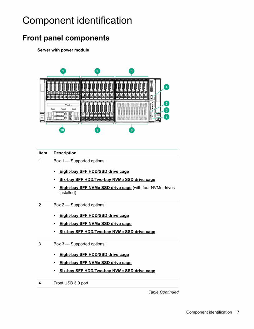
Component identificationFront panel components
Server with power module
Item Description
1 Box 1 — Supported options:
• Eight-bay SFF HDD/SSD drive cage
• Six-bay SFF HDD/Two-bay NVMe SSD drive cage
• Eight-bay SFF NVMe SSD drive cage (with four NVMe drivesinstalled)
2 Box 2 — Supported options:
• Eight-bay SFF HDD/SSD drive cage
• Eight-bay SFF NVMe SSD drive cage
• Six-bay SFF HDD/Two-bay NVMe SSD drive cage
3 Box 3 — Supported options:
• Eight-bay SFF HDD/SSD drive cage
• Eight-bay SFF NVMe SSD drive cage
• Six-bay SFF HDD/Two-bay NVMe SSD drive cage
4 Front USB 3.0 port
Table Continued
Component identification 7
Item Description
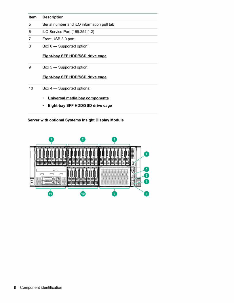
5 Serial number and iLO information pull tab
6 iLO Service Port (169.254.1.2)
7 Front USB 3.0 port
8 Box 6 — Supported option:
Eight-bay SFF HDD/SSD drive cage
9 Box 5 — Supported option:
Eight-bay SFF HDD/SSD drive cage
10 Box 4 — Supported options:
• Universal media bay components
• Eight-bay SFF HDD/SSD drive cage
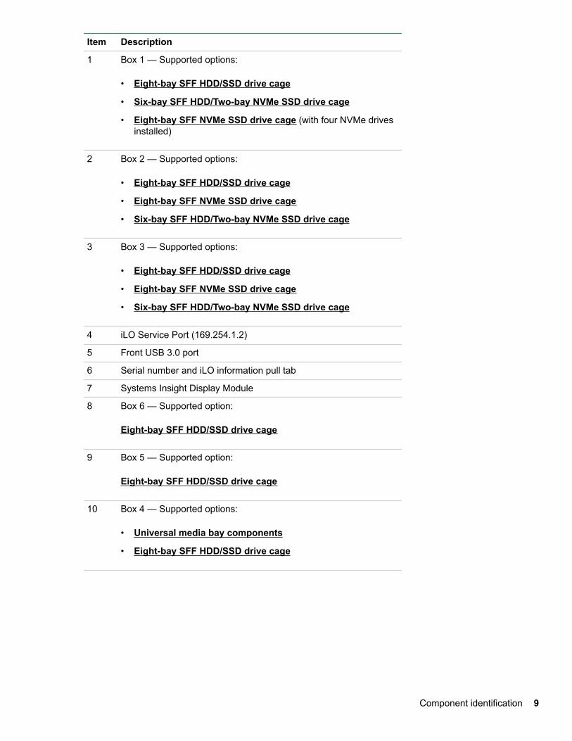
Server with optional Systems Insight Display Module
8 Component identification
Item Description
1 Box 1 — Supported options:
• Eight-bay SFF HDD/SSD drive cage
• Six-bay SFF HDD/Two-bay NVMe SSD drive cage
• Eight-bay SFF NVMe SSD drive cage (with four NVMe drivesinstalled)
2 Box 2 — Supported options:
• Eight-bay SFF HDD/SSD drive cage
• Eight-bay SFF NVMe SSD drive cage
• Six-bay SFF HDD/Two-bay NVMe SSD drive cage
3 Box 3 — Supported options:
• Eight-bay SFF HDD/SSD drive cage
• Eight-bay SFF NVMe SSD drive cage
• Six-bay SFF HDD/Two-bay NVMe SSD drive cage
4 iLO Service Port (169.254.1.2)
5 Front USB 3.0 port
6 Serial number and iLO information pull tab
7 Systems Insight Display Module
8 Box 6 — Supported option:
Eight-bay SFF HDD/SSD drive cage
9 Box 5 — Supported option:
Eight-bay SFF HDD/SSD drive cage
10 Box 4 — Supported options:
• Universal media bay components
• Eight-bay SFF HDD/SSD drive cage
Component identification 9
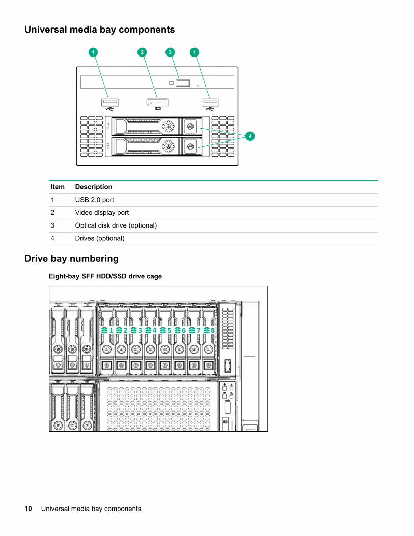
Universal media bay components
Item Description
1 USB 2.0 port
2 Video display port
3 Optical disk drive (optional)
4 Drives (optional)
Drive bay numbering
Eight-bay SFF HDD/SSD drive cage
10 Universal media bay components
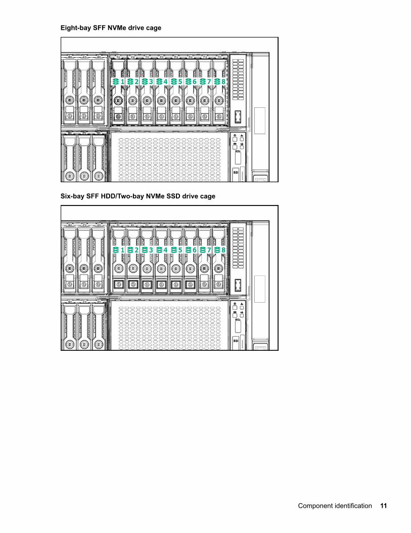
Eight-bay SFF NVMe drive cage
Six-bay SFF HDD/Two-bay NVMe SSD drive cage
Component identification 11
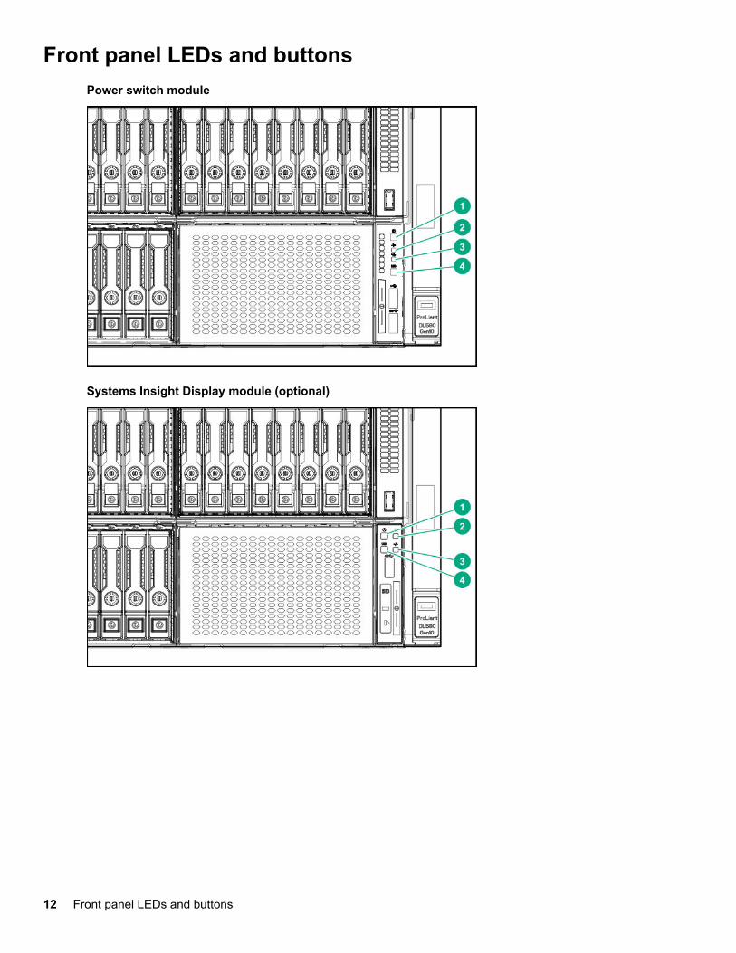
Front panel LEDs and buttonsPower switch module
Systems Insight Display module (optional)
12 Front panel LEDs and buttons
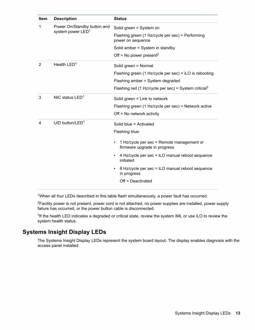
Item Description Status
1 Power On/Standby button andsystem power LED1
Solid green = System on
Flashing green (1 Hz/cycle per sec) = Performingpower on sequence
Solid amber = System in standby
Off = No power present2
2 Health LED1 Solid green = Normal
Flashing green (1 Hz/cycle per sec) = iLO is rebooting.
Flashing amber = System degraded
Flashing red (1 Hz/cycle per sec) = System critical3
3 NIC status LED1 Solid green = Link to network
Flashing green (1 Hz/cycle per sec) = Network active
Off = No network activity
4 UID button/LED1 Solid blue = Activated
Flashing blue:
• 1 Hz/cycle per sec = Remote management orfirmware upgrade in progress
• 4 Hz/cycle per sec = iLO manual reboot sequenceinitiated
• 8 Hz/cycle per sec = iLO manual reboot sequencein progress
Off = Deactivated
1When all four LEDs described in this table flash simultaneously, a power fault has occurred.2Facility power is not present, power cord is not attached, no power supplies are installed, power supplyfailure has occurred, or the power button cable is disconnected.3If the health LED indicates a degraded or critical state, review the system IML or use iLO to review thesystem health status.
Systems Insight Display LEDsThe Systems Insight Display LEDs represent the system board layout. The display enables diagnosis with theaccess panel installed.
Systems Insight Display LEDs 13
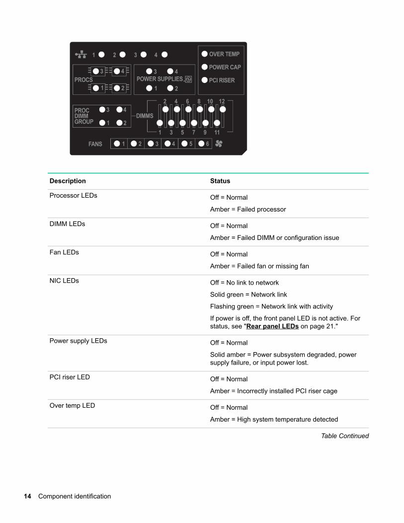
Description Status
Processor LEDs Off = Normal
Amber = Failed processor
DIMM LEDs Off = Normal
Amber = Failed DIMM or configuration issue
Fan LEDs Off = Normal
Amber = Failed fan or missing fan
NIC LEDs Off = No link to network
Solid green = Network link
Flashing green = Network link with activity
If power is off, the front panel LED is not active. Forstatus, see "Rear panel LEDs on page 21."
Power supply LEDs Off = Normal
Solid amber = Power subsystem degraded, powersupply failure, or input power lost.
PCI riser LED Off = Normal
Amber = Incorrectly installed PCI riser cage
Over temp LED Off = Normal
Amber = High system temperature detected
Table Continued
14 Component identification
Description Status
Proc DIMM Group LED Off = Normal
Amber = Failed DIMM or configuration issue
Power cap LED Off = System is in standby, or no cap is set.
Solid green = Power cap applied
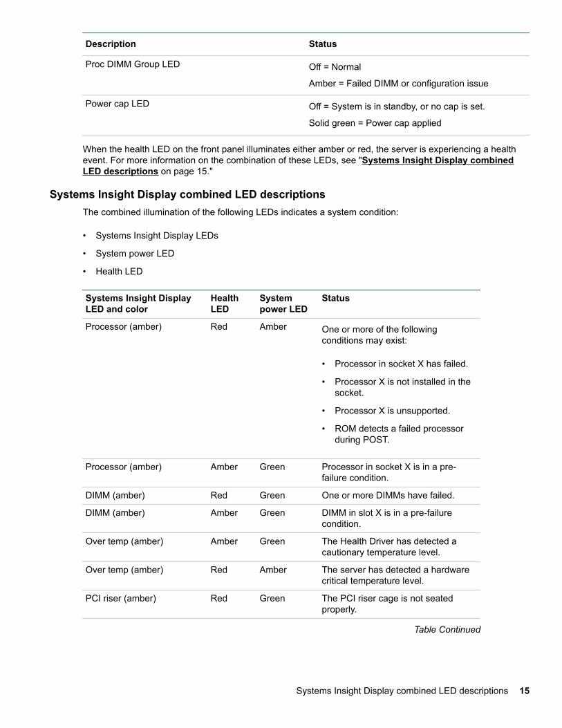
When the health LED on the front panel illuminates either amber or red, the server is experiencing a healthevent. For more information on the combination of these LEDs, see "Systems Insight Display combinedLED descriptions on page 15."
Systems Insight Display combined LED descriptionsThe combined illumination of the following LEDs indicates a system condition:
• Systems Insight Display LEDs
• System power LED
• Health LED
Systems Insight DisplayLED and color
HealthLED
Systempower LED
Status
Processor (amber) Red Amber One or more of the followingconditions may exist:
• Processor in socket X has failed.
• Processor X is not installed in thesocket.
• Processor X is unsupported.
• ROM detects a failed processorduring POST.
Processor (amber) Amber Green Processor in socket X is in a pre-failure condition.
DIMM (amber) Red Green One or more DIMMs have failed.
DIMM (amber) Amber Green DIMM in slot X is in a pre-failurecondition.
Over temp (amber) Amber Green The Health Driver has detected acautionary temperature level.
Over temp (amber) Red Amber The server has detected a hardwarecritical temperature level.
PCI riser (amber) Red Green The PCI riser cage is not seatedproperly.
Table Continued
Systems Insight Display combined LED descriptions 15
Systems Insight DisplayLED and color
HealthLED
Systempower LED
Status
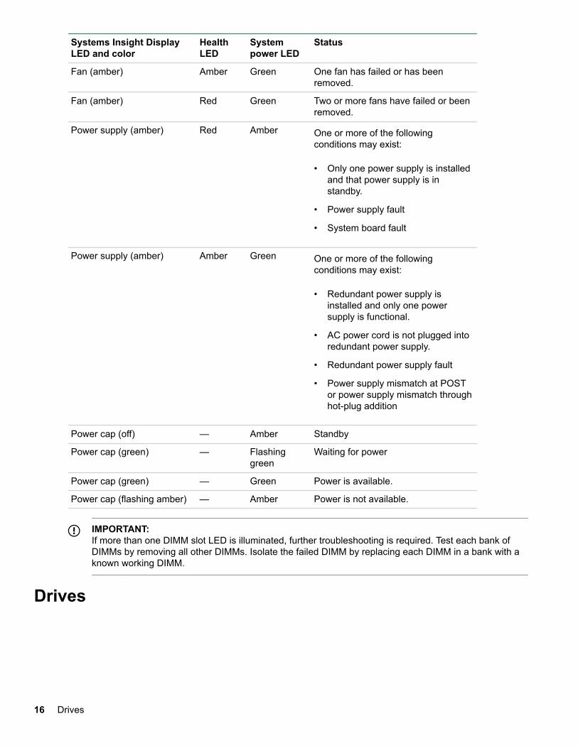
Fan (amber) Amber Green One fan has failed or has beenremoved.
Fan (amber) Red Green Two or more fans have failed or beenremoved.
Power supply (amber) Red Amber One or more of the followingconditions may exist:
• Only one power supply is installedand that power supply is instandby.
• Power supply fault
• System board fault
Power supply (amber) Amber Green One or more of the followingconditions may exist:
• Redundant power supply isinstalled and only one powersupply is functional.
• AC power cord is not plugged intoredundant power supply.
• Redundant power supply fault
• Power supply mismatch at POSTor power supply mismatch throughhot-plug addition
Power cap (off) — Amber Standby
Power cap (green) — Flashinggreen
Waiting for power
Power cap (green) — Green Power is available.
Power cap (flashing amber) — Amber Power is not available.
IMPORTANT:If more than one DIMM slot LED is illuminated, further troubleshooting is required. Test each bank ofDIMMs by removing all other DIMMs. Isolate the failed DIMM by replacing each DIMM in a bank with aknown working DIMM.
Drives
16 Drives
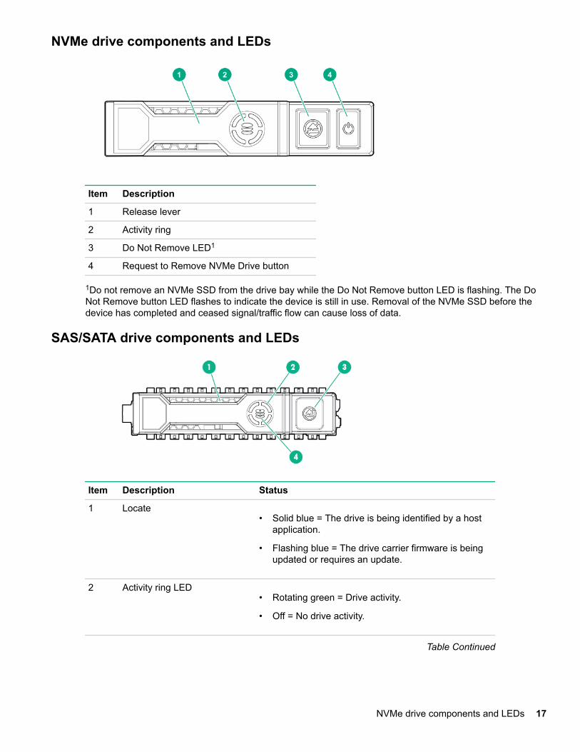
NVMe drive components and LEDs
Item Description
1 Release lever
2 Activity ring
3 Do Not Remove LED1
4 Request to Remove NVMe Drive button
1Do not remove an NVMe SSD from the drive bay while the Do Not Remove button LED is flashing. The DoNot Remove button LED flashes to indicate the device is still in use. Removal of the NVMe SSD before thedevice has completed and ceased signal/traffic flow can cause loss of data.
SAS/SATA drive components and LEDs
Item Description Status
1 Locate• Solid blue = The drive is being identified by a host
application.
• Flashing blue = The drive carrier firmware is beingupdated or requires an update.
2 Activity ring LED• Rotating green = Drive activity.
• Off = No drive activity.
Table Continued
NVMe drive components and LEDs 17
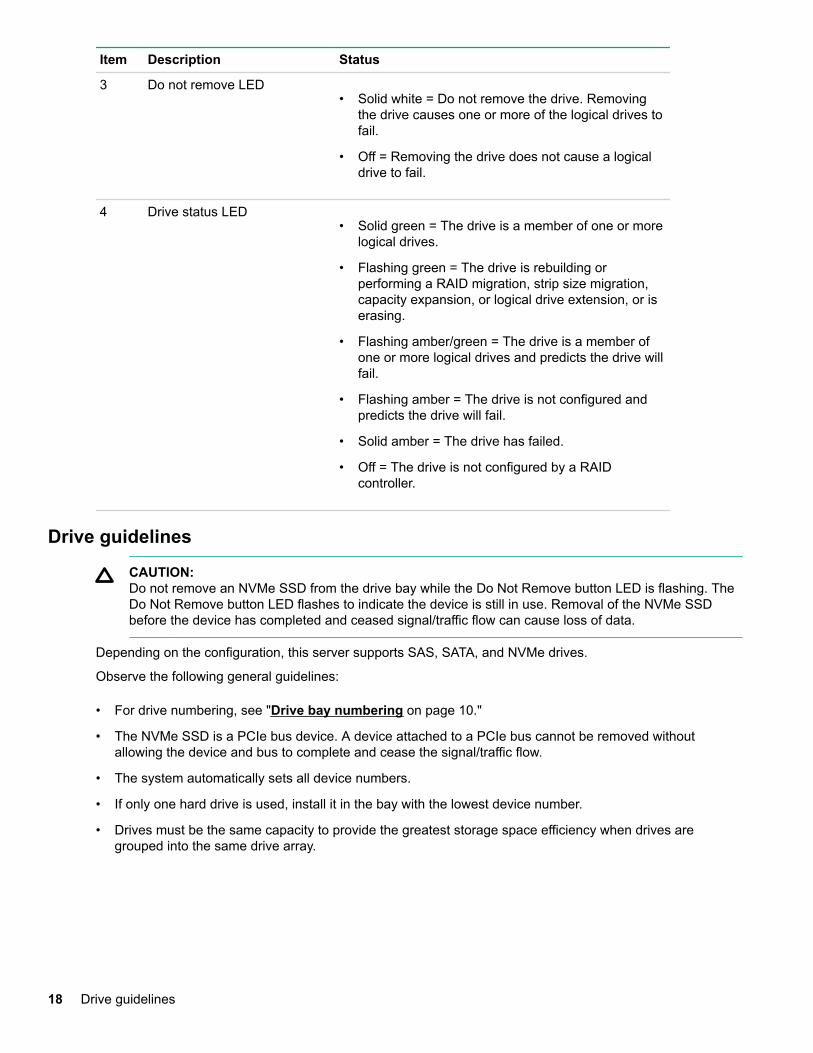
Item Description Status
3 Do not remove LED• Solid white = Do not remove the drive. Removing
the drive causes one or more of the logical drives tofail.
• Off = Removing the drive does not cause a logicaldrive to fail.
4 Drive status LED• Solid green = The drive is a member of one or more
logical drives.
• Flashing green = The drive is rebuilding orperforming a RAID migration, strip size migration,capacity expansion, or logical drive extension, or iserasing.
• Flashing amber/green = The drive is a member ofone or more logical drives and predicts the drive willfail.
• Flashing amber = The drive is not configured andpredicts the drive will fail.
• Solid amber = The drive has failed.
• Off = The drive is not configured by a RAIDcontroller.
Drive guidelines
CAUTION:Do not remove an NVMe SSD from the drive bay while the Do Not Remove button LED is flashing. TheDo Not Remove button LED flashes to indicate the device is still in use. Removal of the NVMe SSDbefore the device has completed and ceased signal/traffic flow can cause loss of data.
Depending on the configuration, this server supports SAS, SATA, and NVMe drives.
Observe the following general guidelines:
• For drive numbering, see "Drive bay numbering on page 10."
• The NVMe SSD is a PCIe bus device. A device attached to a PCIe bus cannot be removed withoutallowing the device and bus to complete and cease the signal/traffic flow.
• The system automatically sets all device numbers.
• If only one hard drive is used, install it in the bay with the lowest device number.
• Drives must be the same capacity to provide the greatest storage space efficiency when drives aregrouped into the same drive array.
18 Drive guidelines
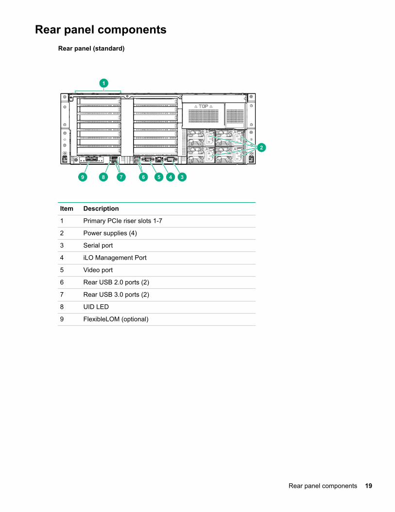
Rear panel componentsRear panel (standard)
Item Description
1 Primary PCIe riser slots 1-7
2 Power supplies (4)
3 Serial port
4 iLO Management Port
5 Video port
6 Rear USB 2.0 ports (2)
7 Rear USB 3.0 ports (2)
8 UID LED
9 FlexibleLOM (optional)
Rear panel components 19
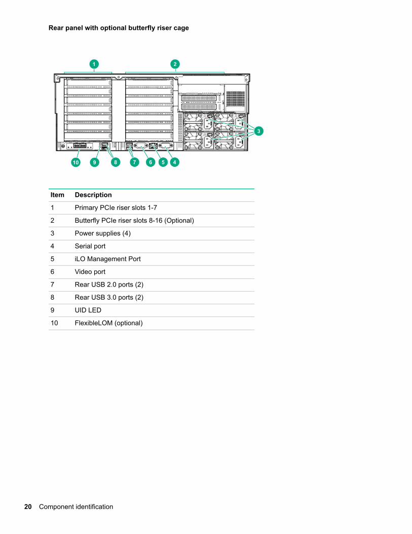
Rear panel with optional butterfly riser cage
Item Description
1 Primary PCIe riser slots 1-7
2 Butterfly PCIe riser slots 8-16 (Optional)
3 Power supplies (4)
4 Serial port
5 iLO Management Port
6 Video port
7 Rear USB 2.0 ports (2)
8 Rear USB 3.0 ports (2)
9 UID LED
10 FlexibleLOM (optional)
20 Component identification
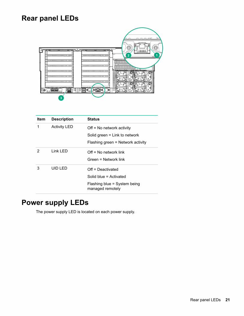
Rear panel LEDs
Item Description Status
1 Activity LED Off = No network activity
Solid green = Link to network
Flashing green = Network activity
2 Link LED Off = No network link
Green = Network link
3 UID LED Off = Deactivated
Solid blue = Activated
Flashing blue = System beingmanaged remotely
Power supply LEDsThe power supply LED is located on each power supply.
Rear panel LEDs 21
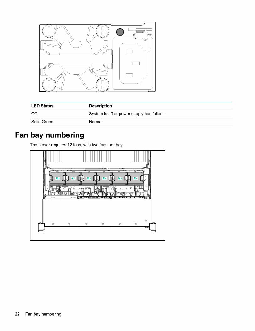
LED Status Description
Off System is off or power supply has failed.
Solid Green Normal
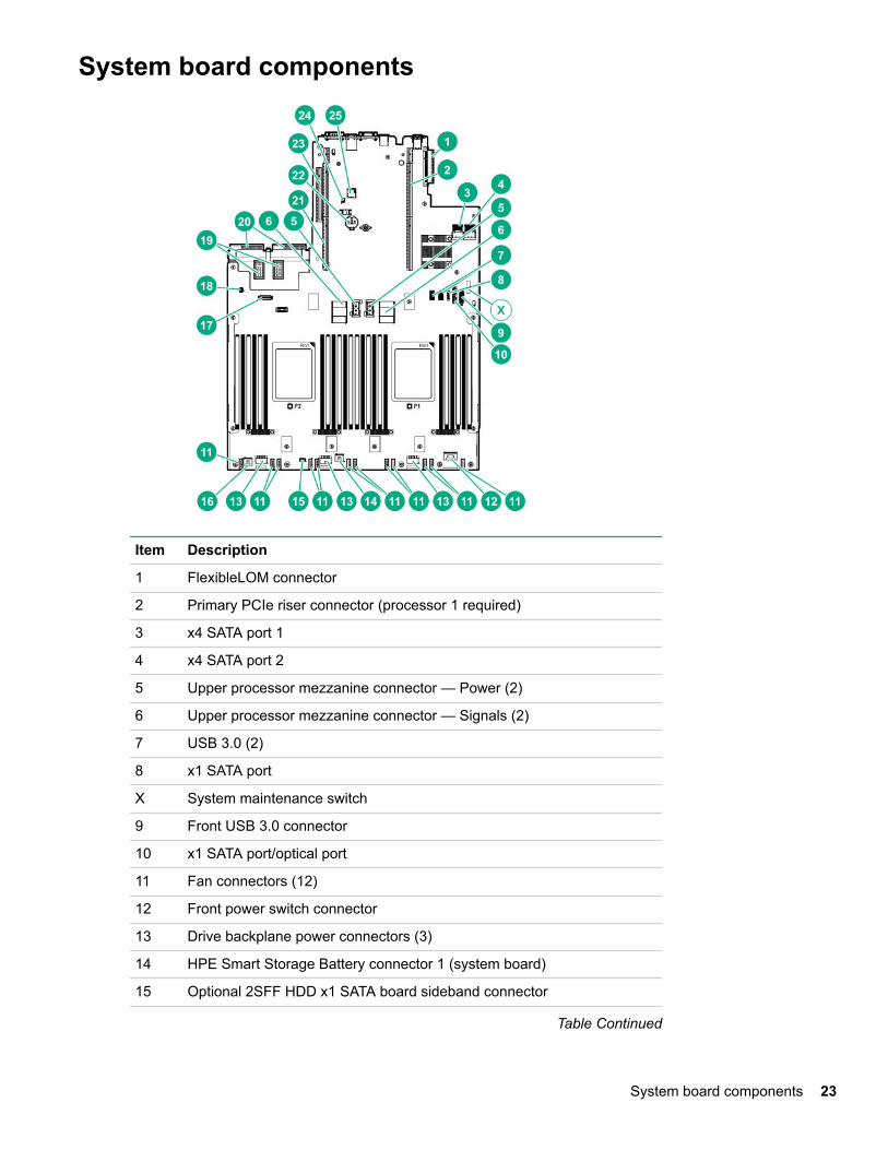
Fan bay numberingThe server requires 12 fans, with two fans per bay.
22 Fan bay numbering
System board components
Item Description
1 FlexibleLOM connector
2 Primary PCIe riser connector (processor 1 required)
3 x4 SATA port 1
4 x4 SATA port 2
5 Upper processor mezzanine connector — Power (2)
6 Upper processor mezzanine connector — Signals (2)
7 USB 3.0 (2)
8 x1 SATA port
X System maintenance switch
9 Front USB 3.0 connector
10 x1 SATA port/optical port
11 Fan connectors (12)
12 Front power switch connector
13 Drive backplane power connectors (3)
14 HPE Smart Storage Battery connector 1 (system board)
15 Optional 2SFF HDD x1 SATA board sideband connector
Table Continued
System board components 23
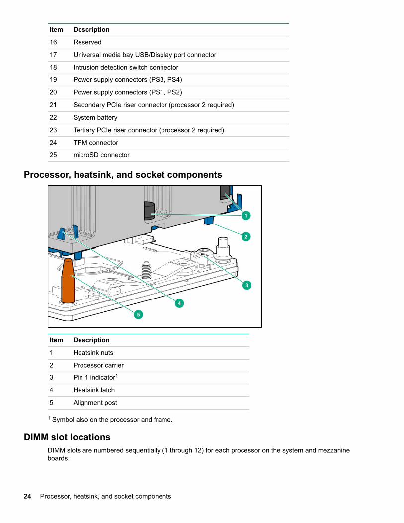
Item Description
16 Reserved
17 Universal media bay USB/Display port connector
18 Intrusion detection switch connector
19 Power supply connectors (PS3, PS4)
20 Power supply connectors (PS1, PS2)
21 Secondary PCIe riser connector (processor 2 required)
22 System battery
23 Tertiary PCIe riser connector (processor 2 required)
24 TPM connector
25 microSD connector
Processor, heatsink, and socket components
Item Description
1 Heatsink nuts
2 Processor carrier
3 Pin 1 indicator1
4 Heatsink latch
5 Alignment post
1 Symbol also on the processor and frame.
DIMM slot locationsDIMM slots are numbered sequentially (1 through 12) for each processor on the system and mezzanineboards.
24 Processor, heatsink, and socket components
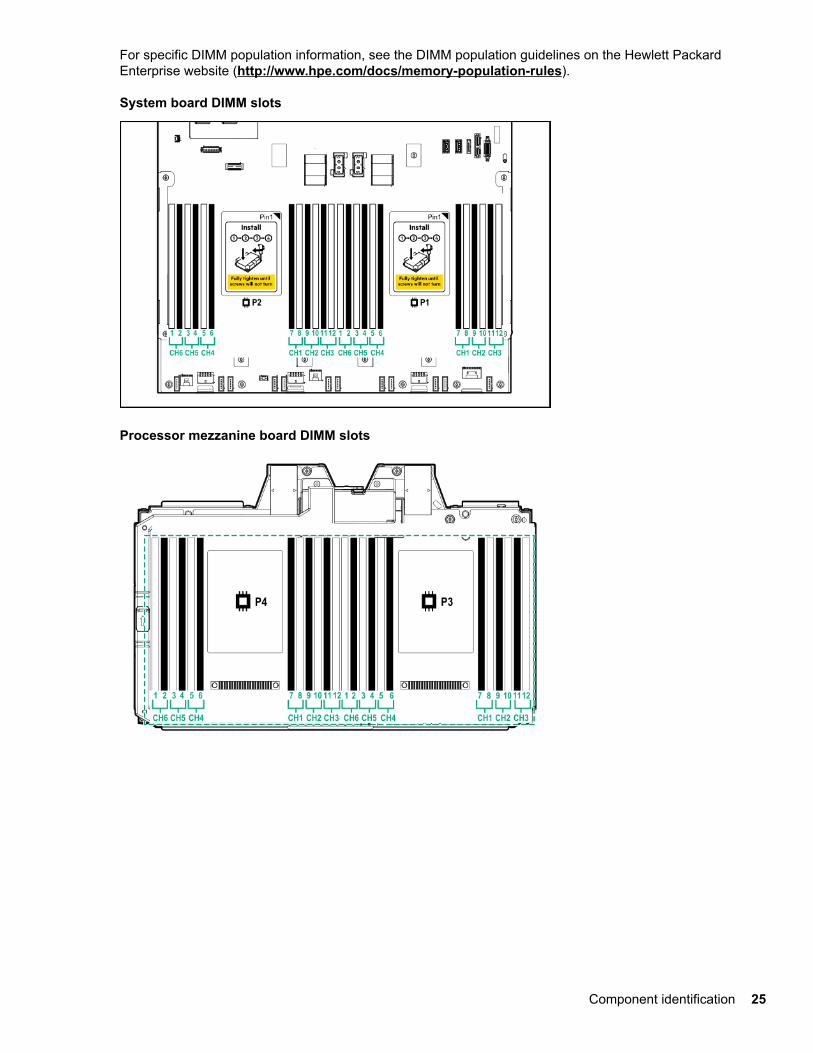
For specific DIMM population information, see the DIMM population guidelines on the Hewlett PackardEnterprise website (http://www.hpe.com/docs/memory-population-rules).
System board DIMM slots
Processor mezzanine board DIMM slots
Component identification 25
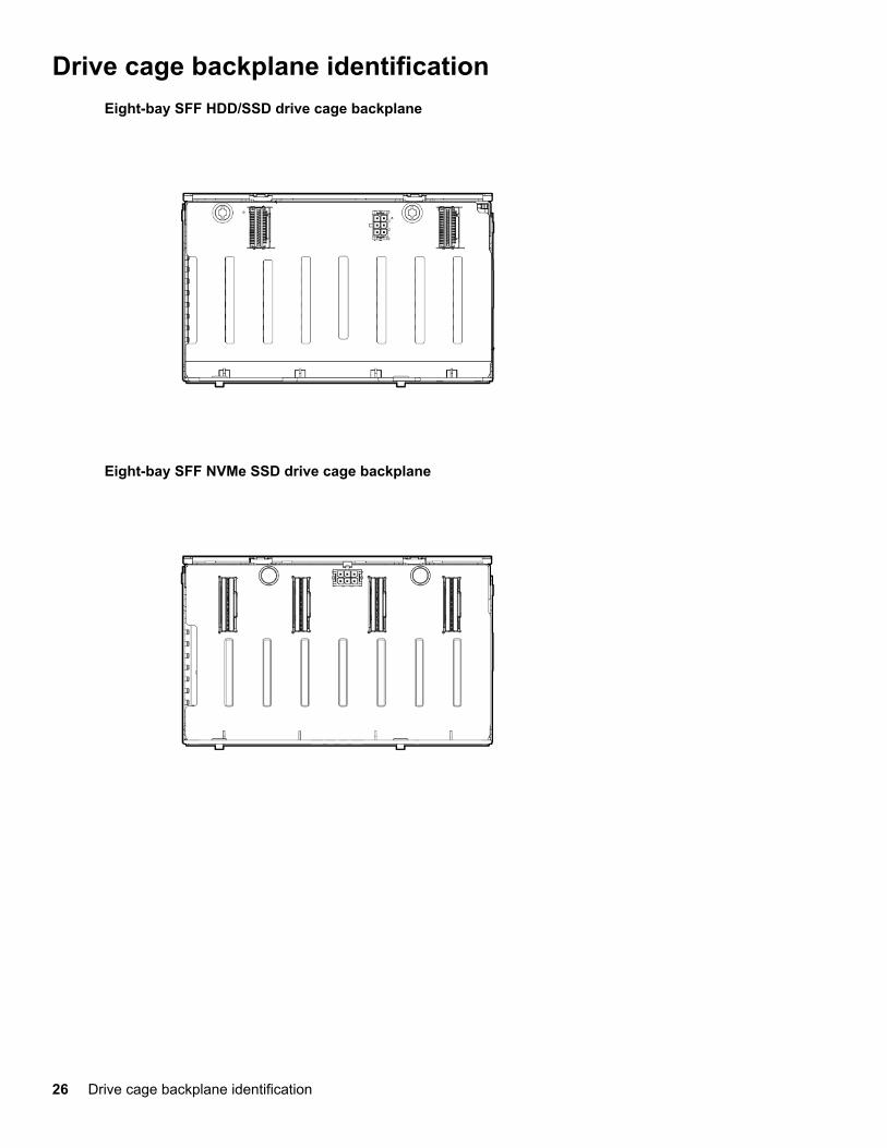
Drive cage backplane identificationEight-bay SFF HDD/SSD drive cage backplane
Eight-bay SFF NVMe SSD drive cage backplane
26 Drive cage backplane identification
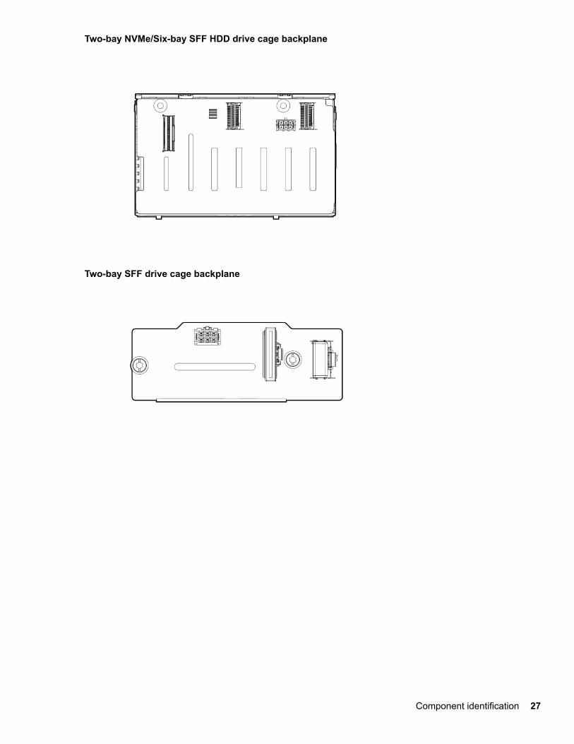
Two-bay NVMe/Six-bay SFF HDD drive cage backplane
Two-bay SFF drive cage backplane
Component identification 27
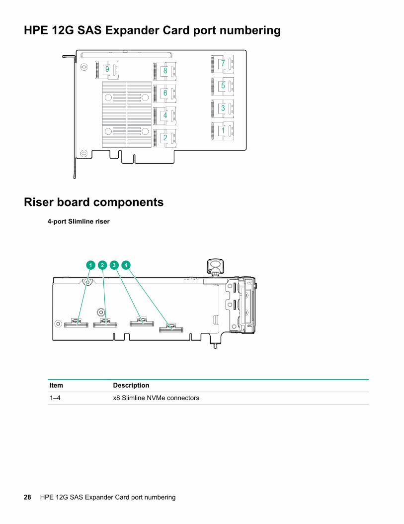
HPE 12G SAS Expander Card port numbering
Riser board components4-port Slimline riser
Item Description
1–4 x8 Slimline NVMe connectors
28 HPE 12G SAS Expander Card port numbering
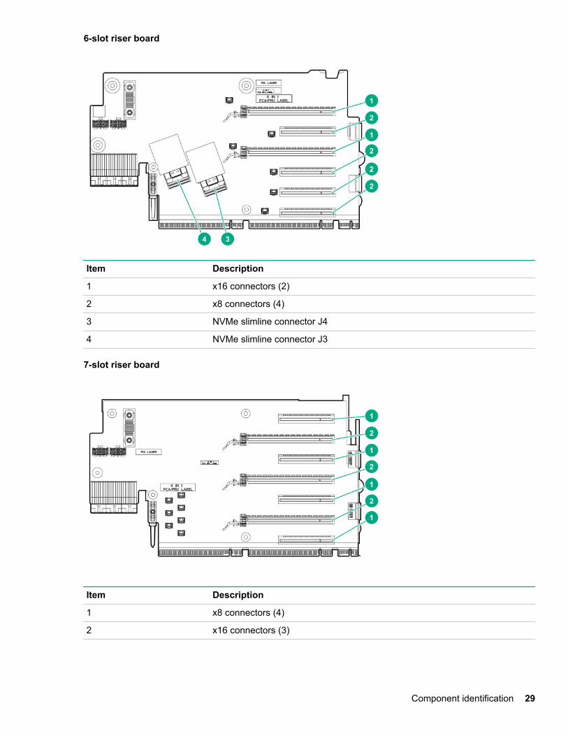
6-slot riser board
Item Description
1 x16 connectors (2)
2 x8 connectors (4)
3 NVMe slimline connector J4
4 NVMe slimline connector J3
7-slot riser board
Item Description
1 x8 connectors (4)
2 x16 connectors (3)
Component identification 29
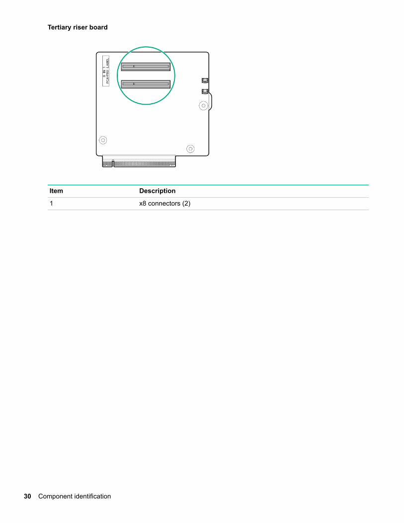
Tertiary riser board
Item Description
1 x8 connectors (2)
30 Component identification
OperationsPower up the server
Procedure
To power up the server, press the Power On/Standby button.
Power down the serverBefore powering down the server for any upgrade or maintenance procedures, perform a backup of criticalserver data and programs.
IMPORTANT:
When the server is in standby mode, auxiliary power is still being provided to the system.
To power down the server, use one of the following methods:
• Press and release the Power On/Standby button.
This method initiates a controlled shutdown of applications and the OS before the server enters standbymode.
• Press and hold the Power On/Standby button for more than 4 seconds to force the server to enter standbymode.
This method forces the server to enter standby mode without properly exiting applications and the OS. Ifan application stops responding, you can use this method to force a shutdown.
• Use a virtual power button selection through iLO.
This method initiates a controlled remote shutdown of applications and the OS before the server entersstandby mode.
Before proceeding, verify that the server is in standby mode by observing that the system power LED isamber.
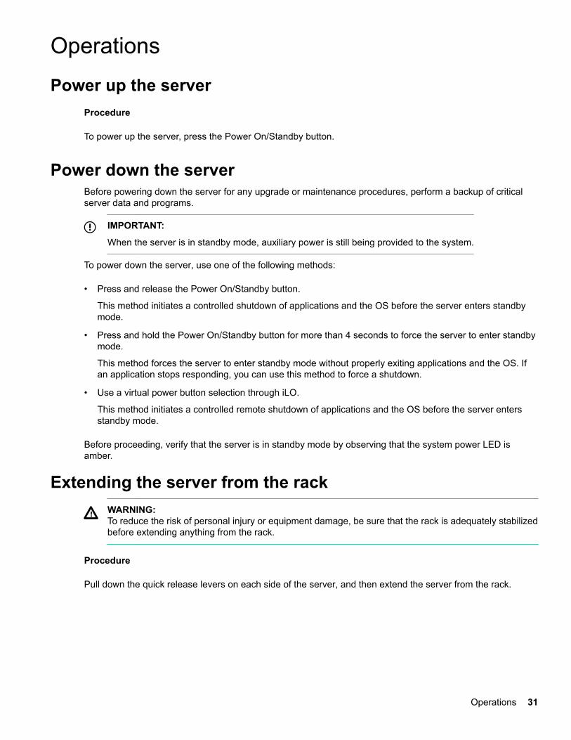
Extending the server from the rackWARNING:To reduce the risk of personal injury or equipment damage, be sure that the rack is adequately stabilizedbefore extending anything from the rack.
Procedure
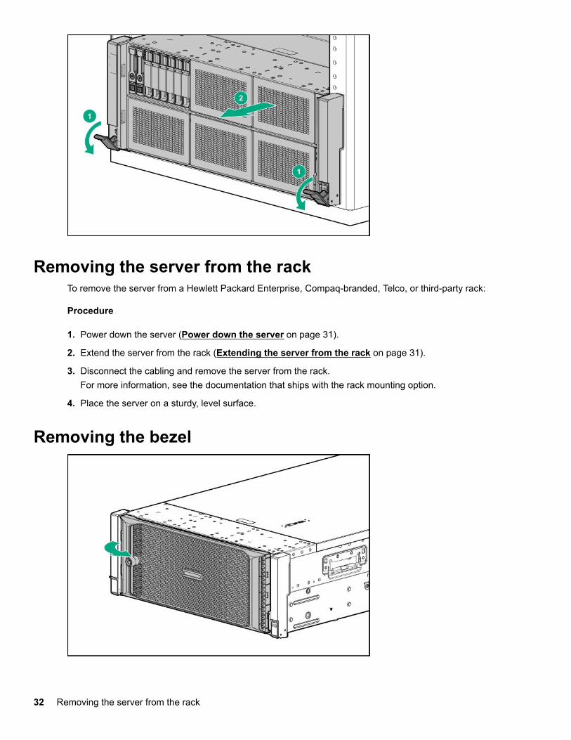
Pull down the quick release levers on each side of the server, and then extend the server from the rack.
Operations 31
Removing the server from the rackTo remove the server from a Hewlett Packard Enterprise, Compaq-branded, Telco, or third-party rack:
Procedure
1. Power down the server (Power down the server on page 31).
2. Extend the server from the rack (Extending the server from the rack on page 31).
3. Disconnect the cabling and remove the server from the rack.For more information, see the documentation that ships with the rack mounting option.
4. Place the server on a sturdy, level surface.
Removing the bezel
32 Removing the server from the rack
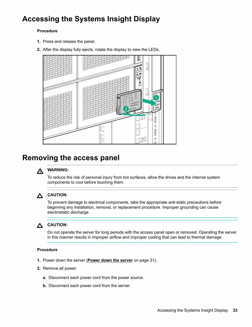
Accessing the Systems Insight DisplayProcedure
1. Press and release the panel.
2. After the display fully ejects, rotate the display to view the LEDs.
Removing the access panelWARNING:
To reduce the risk of personal injury from hot surfaces, allow the drives and the internal systemcomponents to cool before touching them.
CAUTION:
To prevent damage to electrical components, take the appropriate anti-static precautions beforebeginning any installation, removal, or replacement procedure. Improper grounding can causeelectrostatic discharge.
CAUTION:
Do not operate the server for long periods with the access panel open or removed. Operating the serverin this manner results in improper airflow and improper cooling that can lead to thermal damage.
Procedure
1. Power down the server (Power down the server on page 31).
2. Remove all power:
a. Disconnect each power cord from the power source.
b. Disconnect each power cord from the server.
Accessing the Systems Insight Display 33
3. Do one of the following:
• Extend the server from the rack (Extending the server from the rack on page 31).
• Remove the server from the rack (Removing the server from the rack on page 32).
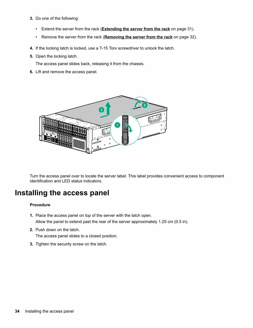
4. If the locking latch is locked, use a T-15 Torx screwdriver to unlock the latch.
5. Open the locking latch.
The access panel slides back, releasing it from the chassis.
6. Lift and remove the access panel.
Turn the access panel over to locate the server label. This label provides convenient access to componentidentification and LED status indicators.
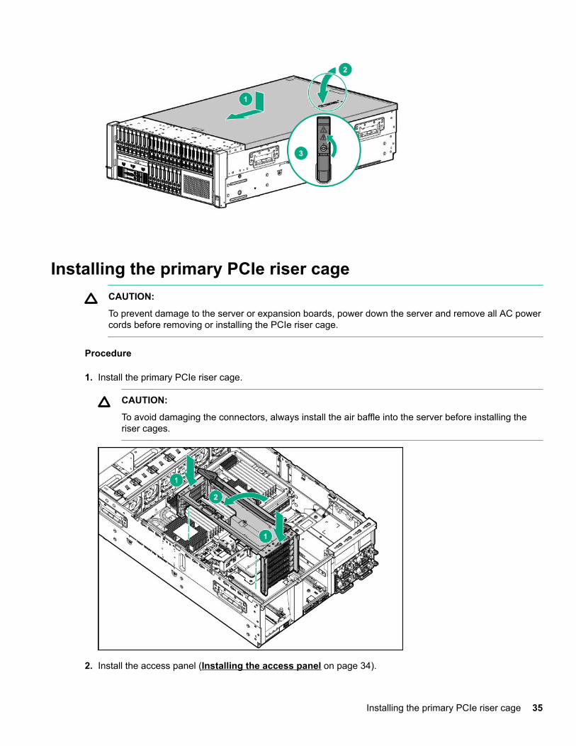
Installing the access panelProcedure
1. Place the access panel on top of the server with the latch open.Allow the panel to extend past the rear of the server approximately 1.25 cm (0.5 in).
2. Push down on the latch.The access panel slides to a closed position.
3. Tighten the security screw on the latch.
34 Installing the access panel
Installing the primary PCIe riser cageCAUTION:
To prevent damage to the server or expansion boards, power down the server and remove all AC powercords before removing or installing the PCIe riser cage.
Procedure
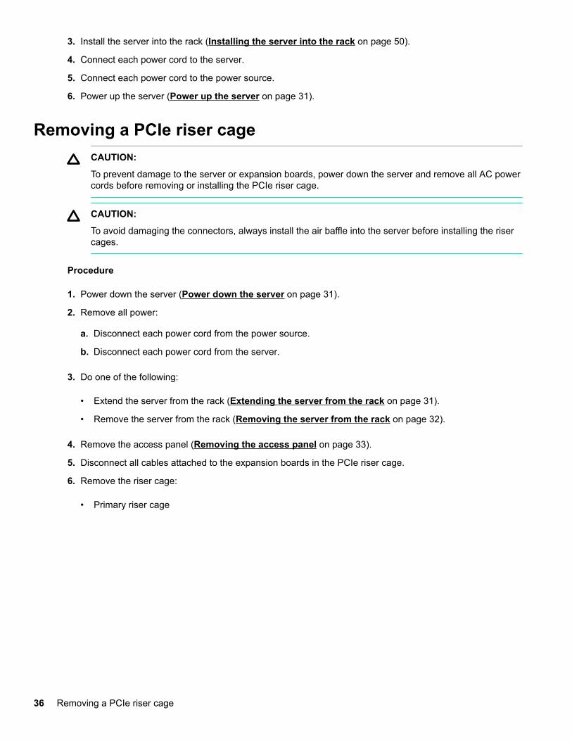
1. Install the primary PCIe riser cage.
CAUTION:
To avoid damaging the connectors, always install the air baffle into the server before installing theriser cages.
2. Install the access panel (Installing the access panel on page 34).
Installing the primary PCIe riser cage 35
3. Install the server into the rack (Installing the server into the rack on page 50).
4. Connect each power cord to the server.
5. Connect each power cord to the power source.
6. Power up the server (Power up the server on page 31).
Removing a PCIe riser cageCAUTION:
To prevent damage to the server or expansion boards, power down the server and remove all AC powercords before removing or installing the PCIe riser cage.
CAUTION:
To avoid damaging the connectors, always install the air baffle into the server before installing the risercages.
Procedure
1. Power down the server (Power down the server on page 31).
2. Remove all power:
a. Disconnect each power cord from the power source.
b. Disconnect each power cord from the server.
3. Do one of the following:
• Extend the server from the rack (Extending the server from the rack on page 31).
• Remove the server from the rack (Removing the server from the rack on page 32).
4. Remove the access panel (Removing the access panel on page 33).
5. Disconnect all cables attached to the expansion boards in the PCIe riser cage.
6. Remove the riser cage:
• Primary riser cage
36 Removing a PCIe riser cage
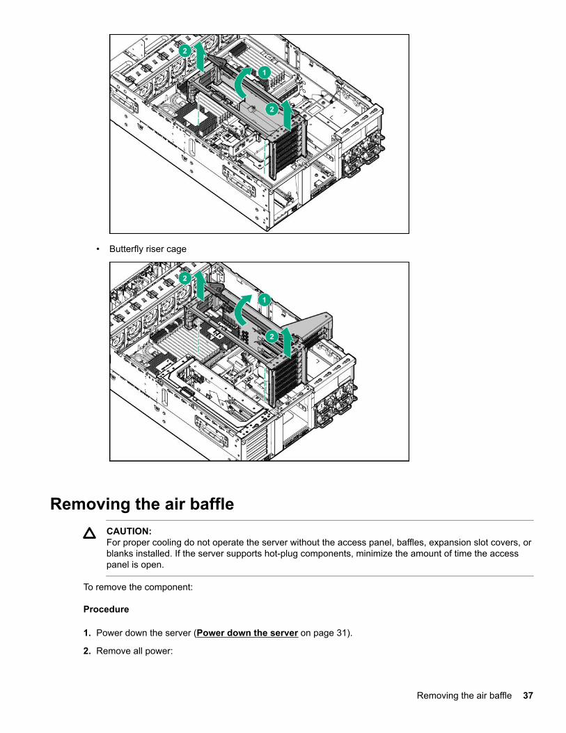
• Butterfly riser cage
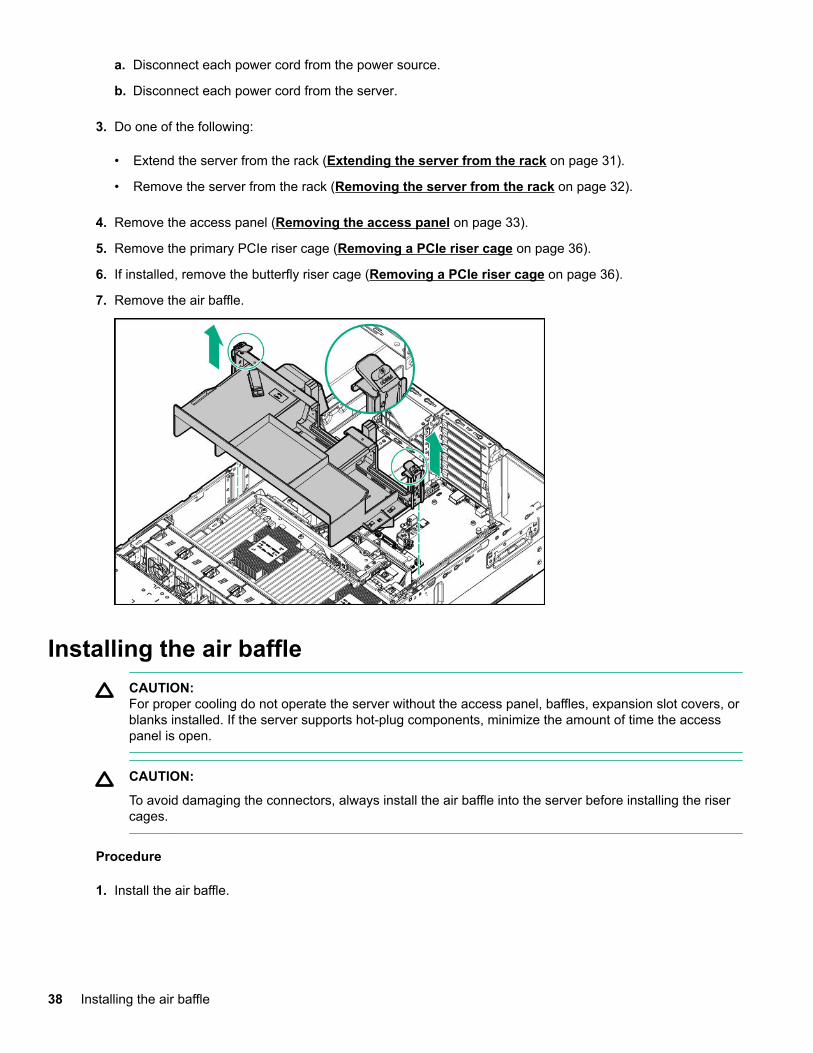
Removing the air baffleCAUTION:For proper cooling do not operate the server without the access panel, baffles, expansion slot covers, orblanks installed. If the server supports hot-plug components, minimize the amount of time the accesspanel is open.
To remove the component:
Procedure
1. Power down the server (Power down the server on page 31).
2. Remove all power:
Removing the air baffle 37
a. Disconnect each power cord from the power source.
b. Disconnect each power cord from the server.
3. Do one of the following:
• Extend the server from the rack (Extending the server from the rack on page 31).
• Remove the server from the rack (Removing the server from the rack on page 32).
4. Remove the access panel (Removing the access panel on page 33).
5. Remove the primary PCIe riser cage (Removing a PCIe riser cage on page 36).
6. If installed, remove the butterfly riser cage (Removing a PCIe riser cage on page 36).
7. Remove the air baffle.
Installing the air baffleCAUTION:For proper cooling do not operate the server without the access panel, baffles, expansion slot covers, orblanks installed. If the server supports hot-plug components, minimize the amount of time the accesspanel is open.
CAUTION:
To avoid damaging the connectors, always install the air baffle into the server before installing the risercages.
Procedure
1. Install the air baffle.
38 Installing the air baffle
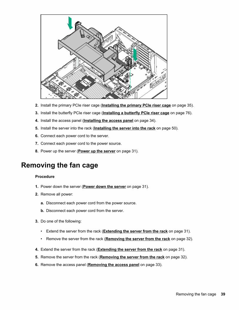
2. Install the primary PCIe riser cage (Installing the primary PCIe riser cage on page 35).
3. Install the butterfly PCIe riser cage (Installing a butterfly PCIe riser cage on page 76).
4. Install the access panel (Installing the access panel on page 34).
5. Install the server into the rack (Installing the server into the rack on page 50).
6. Connect each power cord to the server.
7. Connect each power cord to the power source.
8. Power up the server (Power up the server on page 31).
Removing the fan cageProcedure
1. Power down the server (Power down the server on page 31).
2. Remove all power:
a. Disconnect each power cord from the power source.
b. Disconnect each power cord from the server.
3. Do one of the following:
• Extend the server from the rack (Extending the server from the rack on page 31).
• Remove the server from the rack (Removing the server from the rack on page 32).
4. Extend the server from the rack (Extending the server from the rack on page 31).
5. Remove the server from the rack (Removing the server from the rack on page 32).
6. Remove the access panel (Removing the access panel on page 33).
Removing the fan cage 39
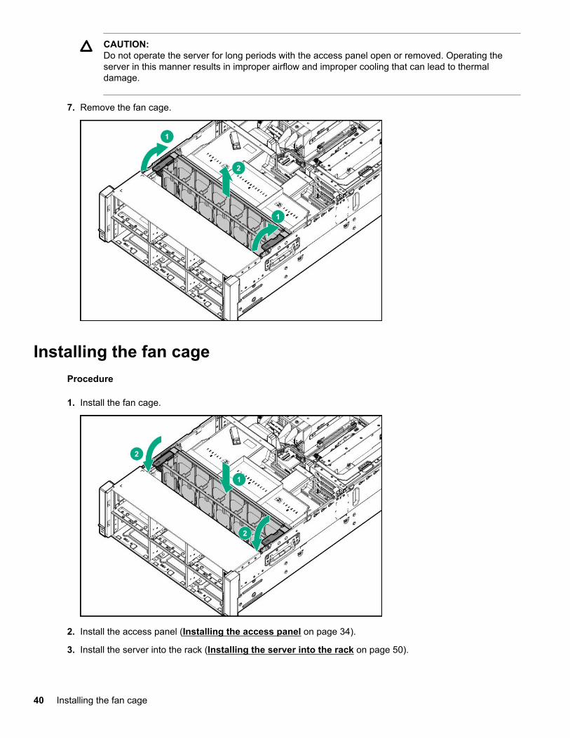
CAUTION:Do not operate the server for long periods with the access panel open or removed. Operating theserver in this manner results in improper airflow and improper cooling that can lead to thermaldamage.
7. Remove the fan cage.
Installing the fan cageProcedure
1. Install the fan cage.
2. Install the access panel (Installing the access panel on page 34).
3. Install the server into the rack (Installing the server into the rack on page 50).
40 Installing the fan cage
4. Connect each power cord to the server.
5. Connect each power cord to the power source.
6. Power up the server (Power up the server on page 31).
Removing the fan cage holdersProcedure
1. Power down the server (Power down the server on page 31).
2. Remove all power:
a. Disconnect each power cord from the power source.
b. Disconnect each power cord from the server.
3. Do one of the following:
• Extend the server from the rack (Extending the server from the rack on page 31).
• Remove the server from the rack (Removing the server from the rack on page 32).
4. Remove the access panel (Removing the access panel on page 33).
5. Remove the fan cage (Removing the fan cage on page 39).
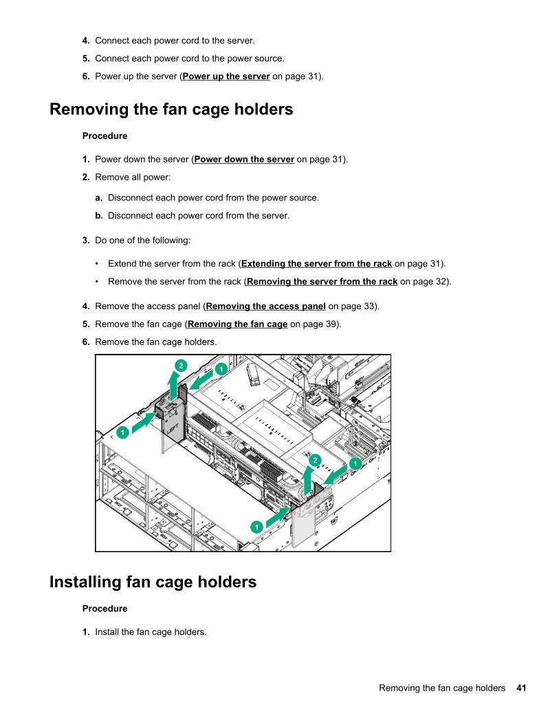
6. Remove the fan cage holders.
Installing fan cage holdersProcedure
1. Install the fan cage holders.
Removing the fan cage holders 41
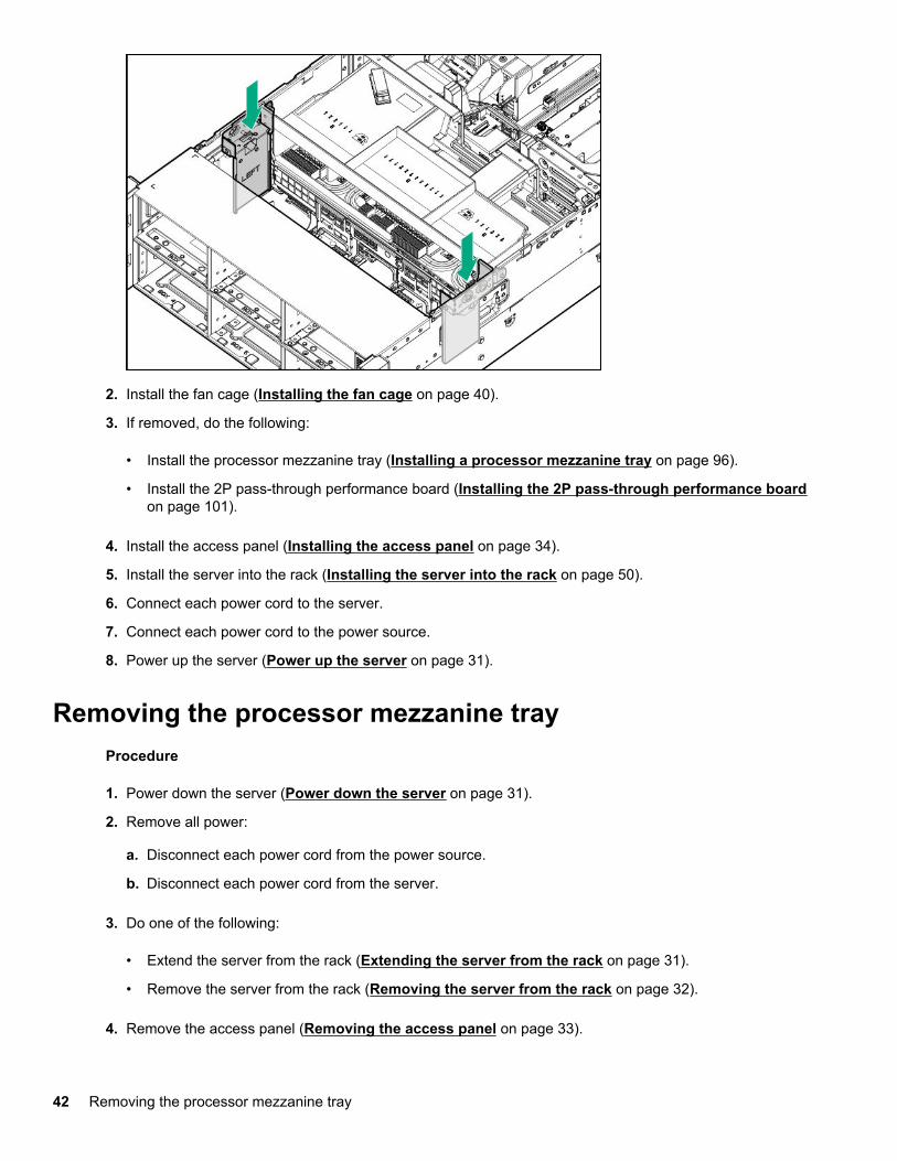
2. Install the fan cage (Installing the fan cage on page 40).
3. If removed, do the following:
• Install the processor mezzanine tray (Installing a processor mezzanine tray on page 96).
• Install the 2P pass-through performance board (Installing the 2P pass-through performance boardon page 101).
4. Install the access panel (Installing the access panel on page 34).
5. Install the server into the rack (Installing the server into the rack on page 50).
6. Connect each power cord to the server.
7. Connect each power cord to the power source.
8. Power up the server (Power up the server on page 31).
Removing the processor mezzanine trayProcedure
1. Power down the server (Power down the server on page 31).
2. Remove all power:
a. Disconnect each power cord from the power source.
b. Disconnect each power cord from the server.
3. Do one of the following:
• Extend the server from the rack (Extending the server from the rack on page 31).
• Remove the server from the rack (Removing the server from the rack on page 32).
4. Remove the access panel (Removing the access panel on page 33).
42 Removing the processor mezzanine tray
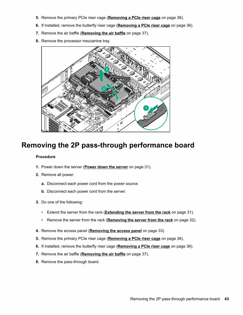
5. Remove the primary PCIe riser cage (Removing a PCIe riser cage on page 36).
6. If installed, remove the butterfly riser cage (Removing a PCIe riser cage on page 36).
7. Remove the air baffle (Removing the air baffle on page 37).
8. Remove the processor mezzanine tray.
Removing the 2P pass-through performance boardProcedure
1. Power down the server (Power down the server on page 31).
2. Remove all power:
a. Disconnect each power cord from the power source.
b. Disconnect each power cord from the server.
3. Do one of the following:
• Extend the server from the rack (Extending the server from the rack on page 31).
• Remove the server from the rack (Removing the server from the rack on page 32).
4. Remove the access panel (Removing the access panel on page 33).
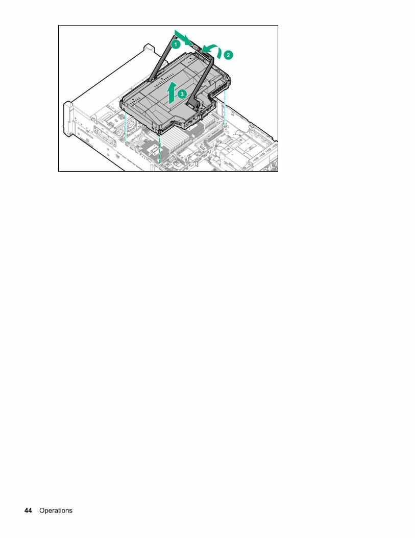
5. Remove the primary PCIe riser cage (Removing a PCIe riser cage on page 36).
6. If installed, remove the butterfly riser cage (Removing a PCIe riser cage on page 36).
7. Remove the air baffle (Removing the air baffle on page 37).
8. Remove the pass-through board.
Removing the 2P pass-through performance board 43
44 Operations
SetupHPE support services
Delivered by experienced, certified engineers, HPE support services help you keep your servers up andrunning with support packages tailored specifically for HPE ProLiant systems. HPE support services let youintegrate both hardware and software support into a single package. A number of service level options areavailable to meet your business and IT needs.
HPE support services offer upgraded service levels to expand the standard product warranty with easy-to-buy, easy-to-use support packages that will help you make the most of your server investments. Some of theHPE support services for hardware, software or both are:
• Foundation Care – Keep systems running.
◦ 6-Hour Call-to-Repair
◦ 4-Hour 24x7
◦ Next Business Day
• Proactive Care – Help prevent service incidents and get you to technical experts when there is one.
◦ 6-Hour Call-to-Repair
◦ 4-Hour 24x7
◦ Next Business Day
• Startup and implementation services for both hardware and software
• HPE Education Services – Help train your IT staff.
For more information on HPE support services, see the Hewlett Packard Enterprise website.
Setup overviewProcedure
1. Review the operational requirements for the server (Operational requirements on page 46).
2. Read the following safety notices, warnings, and cautions:
• Server warnings and cautions (Server warnings and cautions on page 48)
• Rack warnings (Rack warnings on page 48)
• Electrostatic discharge (Electrostatic discharge on page 49)
3. Verify the contents in the server box (Server box contents on page 50).
4. Install hardware options (Installing hardware options on page 53).
5. Install the server into a rack (Installing the server into the rack on page 50).
6. Configure the server (Configuring the server on page 51).
Setup 45
7. Install or deploy an operating system (Operating system on page 51).
8. Register your server (Registering the server on page 52).
Operational requirements
Space and airflow requirementsTo allow for servicing and adequate airflow, observe the following space and airflow requirements whendeciding where to install a rack:
• Leave a minimum clearance of 63.5 cm (25 in) in front of the rack.
• Leave a minimum clearance of 76.2 cm (30 in) behind the rack.
• Leave a minimum clearance of 121.9 cm (48 in) from the back of the rack to the back of another rack orrow of racks.
Hewlett Packard Enterprise servers draw in cool air through the front door and expel warm air through therear door. Therefore, the front and rear rack doors must be adequately ventilated to allow ambient room air toenter the cabinet, and the rear door must be adequately ventilated to allow the warm air to escape from thecabinet.
CAUTION:To prevent improper cooling and damage to the equipment, do not block the ventilation openings.
When vertical space in the rack is not filled by a server or rack component, the gaps between the componentscause changes in airflow through the rack and across the servers. Cover all gaps with blanking panels tomaintain proper airflow.
CAUTION:Always use blanking panels to fill empty vertical spaces in the rack. This arrangement ensures properairflow. Using a rack without blanking panels results in improper cooling that can lead to thermaldamage.
The 9000 and 10000 Series Racks provide proper server cooling from flow-through perforations in the frontand rear doors that provide 64 percent open area for ventilation.
CAUTION:When using a Compaq branded 7000 series rack, install the high airflow rack door insert (PN 327281-B21 for 42U rack, PN 157847-B21 for 22U rack) to provide proper front-to-back airflow and cooling.
CAUTION:
If a third-party rack is used, observe the following additional requirements to ensure adequate airflowand to prevent damage to the equipment:
• Front and rear doors—If the 42U rack includes closing front and rear doors, you must allow 5,350 sqcm (830 sq in) of holes evenly distributed from top to bottom to permit adequate airflow (equivalent tothe required 64 percent open area for ventilation).
• Side—The clearance between the installed rack component and the side panels of the rack must bea minimum of 7 cm (2.75 in).
46 Operational requirements
Temperature requirementsTo ensure continued safe and reliable equipment operation, install or position the system in a well-ventilated,climate-controlled environment.
The maximum recommended ambient operating temperature (TMRA) for most server products is 35°C(95°F). The temperature in the room where the rack is located must not exceed 35°C (95°F).
CAUTION:To reduce the risk of damage to the equipment when installing third-party options:
• Do not permit optional equipment to impede airflow around the server or to increase the internal racktemperature beyond the maximum allowable limits.
• Do not exceed the manufacturer’s TMRA.
Power requirementsInstallation of this equipment must comply with local and regional electrical regulations governing theinstallation of information technology equipment by licensed electricians. This equipment is designed tooperate in installations covered by NFPA 70, 1999 Edition (National Electric Code) and NFPA-75, 1992 (codefor Protection of Electronic Computer/Data Processing Equipment). For electrical power ratings on options,refer to the product rating label or the user documentation supplied with that option.
WARNING:To reduce the risk of personal injury, fire, or damage to the equipment, do not overload the AC supplybranch circuit that provides power to the rack. Consult the electrical authority having jurisdiction overwiring and installation requirements of your facility.
CAUTION:Protect the server from power fluctuations and temporary interruptions with a regulating uninterruptiblepower supply. This device protects the hardware from damage caused by power surges and voltagespikes and keeps the system in operation during a power failure.
Electrical grounding requirementsThe server must be grounded properly for proper operation and safety. In the United States, you must installthe equipment in accordance with NFPA 70, 1999 Edition (National Electric Code), Article 250, as well as anylocal and regional building codes. In Canada, you must install the equipment in accordance with CanadianStandards Association, CSA C22.1, Canadian Electrical Code. In all other countries, you must install theequipment in accordance with any regional or national electrical wiring codes, such as the InternationalElectrotechnical Commission (IEC) Code 364, parts 1 through 7. Furthermore, you must be sure that allpower distribution devices used in the installation, such as branch wiring and receptacles, are listed orcertified grounding-type devices.
Because of the high ground-leakage currents associated with multiple servers connected to the same powersource, recommends the use of a PDU that is either permanently wired to the building’s branch circuit orincludes a nondetachable cord that is wired to an industrial-style plug. NEMA locking-style plugs or thosecomplying with IEC 60309 are considered suitable for this purpose. Using common power outlet strips for theserver is not recommended.
Temperature requirements 47
Server warnings and cautions
WARNING:
This server is heavy. To reduce the risk of personal injury or damage to the equipment:
• Observe local occupational health and safety requirements and guidelines for manual materialhandling.
• Get help to lift and stabilize the product during installation or removal, especially when the product isnot fastened to the rails. Hewlett Packard Enterprise recommends that a minimum of two people arerequired for all rack server installations. If the server is installed higher than chest level, a thirdperson may be required to help align the server.
• Use caution when installing the server in or removing the server from the rack; it is unstable whennot fastened to the rails.
WARNING:
To reduce the risk of personal injury from hot surfaces, allow the drives and the internal systemcomponents to cool before touching them.
WARNING:
To reduce the risk of personal injury, electric shock, or damage to the equipment, remove the powercord to remove power from the server. The front panel Power On/Standby button does not completelyshut off system power. Portions of the power supply and some internal circuitry remain active untilAC/DC power is removed.
CAUTION:
Protect the server from power fluctuations and temporary interruptions with a regulating uninterruptiblepower supply. This device protects the hardware from damage caused by power surges and voltagespikes and keeps the system in operation during a power failure.
CAUTION:
Do not operate the server for long periods with the access panel open or removed. Operating the serverin this manner results in improper airflow and improper cooling that can lead to thermal damage.
Rack warnings
WARNING:To reduce the risk of personal injury or damage to the equipment, be sure that:
• The leveling jacks are extended to the floor.
• The full weight of the rack rests on the leveling jacks.
• The stabilizing feet are attached to the rack if it is a single-rack installation.
• The racks are coupled together in multiple-rack installations.
• Only one component is extended at a time. A rack may become unstable if more than onecomponent is extended for any reason.
48 Server warnings and cautions
WARNING:To reduce the risk of personal injury or equipment damage when unloading a rack:
• At least two people are needed to safely unload the rack from the pallet. An empty 42U rack canweigh as much as 115 kg (253 lb), can stand more than 2.1 m (7 ft) tall, and might become unstablewhen being moved on its casters.
• Never stand in front of the rack when it is rolling down the ramp from the pallet. Always handle therack from both sides.
WARNING:
To reduce the risk of personal injury or damage to the equipment, adequately stabilize the rack beforeextending a component outside the rack. Extend only one component at a time. A rack may becomeunstable if more than one component is extended.
WARNING:
When installing a server in a telco rack, be sure that the rack frame is adequately secured at the top andbottom to the building structure.
Electrostatic dischargeBe aware of the precautions you must follow when setting up the system or handling components. Adischarge of static electricity from a finger or other conductor may damage system boards or other static-sensitive devices. This type of damage may reduce the life expectancy of the system or component.
To prevent electrostatic damage:
• Avoid hand contact by transporting and storing products in static-safe containers.
• Keep electrostatic-sensitive parts in their containers until they arrive at static-free workstations.
• Place parts on a grounded surface before removing them from their containers.
• Avoid touching pins, leads, or circuitry.
• Always be properly grounded when touching a static-sensitive component or assembly. Use one or moreof the following methods when handling or installing electrostatic-sensitive parts:
◦ Use a wrist strap connected by a ground cord to a grounded workstation or computer chassis. Wriststraps are flexible straps with a minimum of 1 megohm ±10 percent resistance in the ground cords. Toprovide proper ground, wear the strap snug against the skin.
◦ Use heel straps, toe straps, or boot straps at standing workstations. Wear the straps on both feet whenstanding on conductive floors or dissipating floor mats.
◦ Use conductive field service tools.
◦ Use a portable field service kit with a folding static-dissipating work mat.
If you do not have any of the suggested equipment for proper grounding, have an authorized resellerinstall the part.
For more information on static electricity or assistance with product installation, contact an authorized reseller.
Electrostatic discharge 49
Server box contentsThe server shipping box contains the following contents:
• A server
• A power cord
• Rack-mounting hardware
• Documentation
Installing hardware optionsInstall any hardware options before initializing the server. For options installation information, refer to theoption documentation. For server-specific information, see "Installing hardware options on page 53."
Installing the server into the rack
CAUTION:
Always plan the rack installation so that the heaviest item is on the bottom of the rack. Install theheaviest item first, and continue to populate the rack from the bottom to the top.
Procedure
1. Install the server and cable management arm into the rack. For more information, see the installationinstructions that ship with the rack.
2. Connect peripheral devices to the server.
WARNING:
To reduce the risk of electric shock, fire, or damage to the equipment, do not plug telephone ortelecommunications connectors into RJ-45 connectors.
3. Connect the power cord to the rear of the server.
4. Secure the cables to the cable management arm.
IMPORTANT:
When using cable management arm components, be sure to leave enough slack in each of thecables to prevent damage to the cables when the server is extended from the rack.
5. Connect the power cord to the AC power source.
50 Server box contents
WARNING:
To reduce the risk of electric shock or damage to the equipment:
• Do not disable the power cord grounding plug. The grounding plug is an important safety feature.
• Plug the power cord into a grounded (earthed) electrical outlet that is easily accessible at alltimes.
• Unplug the power cord from the power supply to disconnect power to the equipment.
• Do not route the power cord where it can be walked on or pinched by items placed against it. Payparticular attention to the plug, electrical outlet, and the point where the cord extends from theserver.
Configuring the serverWhen the server is powered on, the POST screen is displayed. Use the following options to configure theserver:
• System utilities (F9)
Use this option to configure UEFI, RBSU, or other boot settings.
• Intelligent Provisioning (F10)
Use this option to configure drives, access Smart Storage Administrator, or begin installing or deploying anoperating system.
• Boot order (F11)
Use this option to select a boot device.
• Network boot (F12)
Use this option to PXE boot the server from the network.
Operating systemThis ProLiant server does not ship with provisioning media. Everything required to manage and install thesystem software and firmware is preloaded on the server.
To operate properly, the server must have a supported operating system. Attempting to run an unsupportedoperating system can cause serious and unpredictable results. For the latest information on operating systemsupport, see the Hewlett Packard Enterprise website.
Failure to observe UEFI requirements for ProLiant Gen10 servers can result in errors installing the operatingsystem, failure to recognize boot media, and other boot failures. For more information on these requirements,see the HPE UEFI Requirements on the Hewlett Packard Enterprise website.
To install an operating system on the server, use one of the following methods:
• Intelligent Provisioning—For single-server deployment, updating, and provisioning capabilities. For moreinformation, see Installing the operating system with Intelligent Provisioning on page 52.
• Insight Control server provisioning—For multiserver remote OS deployment, use Insight Control serverprovisioning for an automated solution. For more information, see the Insight Control documentation onthe Hewlett Packard Enterprise website.
Configuring the server 51
For additional system software and firmware updates, download the Service Pack for ProLiant from the Hewlett Packard Enterprise website. Software and firmware must be updated before using the server forthe first time, unless any installed software or components require an older version.
For more information, see Keeping the system current on page 136.
For more information on using these installation methods, see the Hewlett Packard Enterprise website.
Installing the operating system with Intelligent Provisioning
Procedure
1. Connect the Ethernet cable between the network connector on the server and a network jack.
2. Press the Power On/Standby button.
3. During server POST, press F10.
4. Complete the initial Preferences and Registration portion of Intelligent Provisioning.
5. At the 1 Start screen, click Configure and Install.
6. To finish the installation, follow the onscreen prompts. An Internet connection is required to update thefirmware and systems software.
Installing or deploying an operating systemBefore installing an operating system, observe the following:
• Be sure to read the HPE UEFI requirements for ProLiant servers on the Hewlett Packard Enterprisewebsite. If UEFI requirements are not met, you might experience boot failures or other errors wheninstalling the operating system.
• Update firmware before using the server for the first time, unless software or components require an olderversion. For more information, see "Keeping the system current on page 136."
• For the latest information on supported operating systems, see the Hewlett Packard Enterprise website.
• The server does not ship with OS media. All system software and firmware is preloaded on the server.
Registering the serverTo experience quicker service and more efficient support, register the product at the Hewlett PackardEnterprise Product Registration website.
52 Installing the operating system with Intelligent Provisioning
Installing hardware optionsBefore powering on the server for the first time, install all hardware options.
Hewlett Packard Enterprise product QuickSpecsFor more information about product features, specifications, options, configurations, and compatibility, see theproduct QuickSpecs on the Hewlett Packard Enterprise website (http://www.hpe.com/info/qs).
Installing a Systems Insight DisplayPrerequisites
Before installing this option, be sure that you have the following:
• The components included with the hardware option kit
• T-10 Torx screwdriver
Procedure
1. Power down the server (Power down the server on page 31).
2. Remove all power:
a. Disconnect each power cord from the power source.
b. Disconnect each power cord from the server.
3. Do one of the following:
• Extend the server from the rack (Extending the server from the rack on page 31).
• Remove the server from the rack (Removing the server from the rack on page 32).
4. Remove the access panel (Removing the access panel on page 33).
5. Remove the primary PCIe riser cage (Removing a PCIe riser cage on page 36).
6. If installed, remove the butterfly riser cage (Removing a PCIe riser cage on page 36).
7. Remove the air baffle (Removing the air baffle on page 37).
8. Remove the fan cage (Removing the fan cage on page 39).
9. If installed, remove the processor mezzanine tray (Removing the processor mezzanine tray on page42).
10. Remove the cabled power switch module. Retain the T-10 screw for later use.
Installing hardware options 53
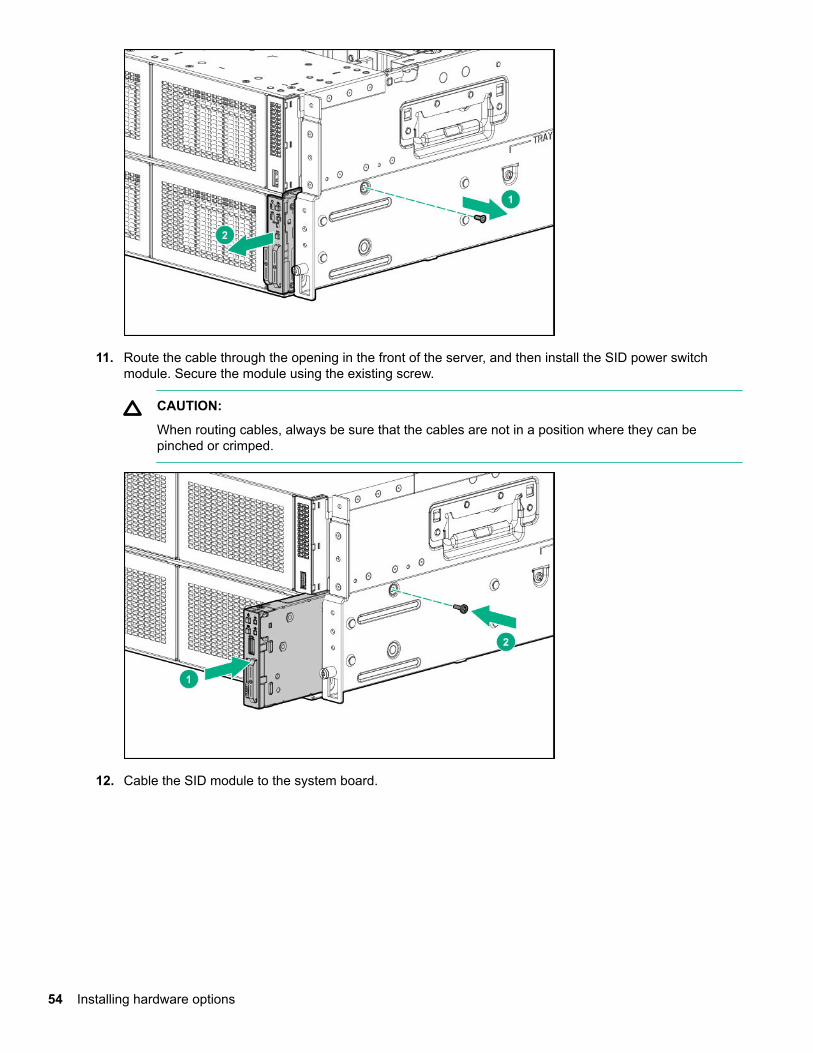
11. Route the cable through the opening in the front of the server, and then install the SID power switchmodule. Secure the module using the existing screw.
CAUTION:
When routing cables, always be sure that the cables are not in a position where they can bepinched or crimped.
12. Cable the SID module to the system board.
54 Installing hardware options
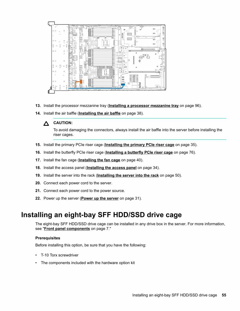
13. Install the processor mezzanine tray (Installing a processor mezzanine tray on page 96).
14. Install the air baffle (Installing the air baffle on page 38).
CAUTION:
To avoid damaging the connectors, always install the air baffle into the server before installing theriser cages.
15. Install the primary PCIe riser cage (Installing the primary PCIe riser cage on page 35).
16. Install the butterfly PCIe riser cage (Installing a butterfly PCIe riser cage on page 76).
17. Install the fan cage (Installing the fan cage on page 40).
18. Install the access panel (Installing the access panel on page 34).
19. Install the server into the rack (Installing the server into the rack on page 50).
20. Connect each power cord to the server.
21. Connect each power cord to the power source.
22. Power up the server (Power up the server on page 31).
Installing an eight-bay SFF HDD/SSD drive cageThe eight-bay SFF HDD/SSD drive cage can be installed in any drive box in the server. For more information,see "Front panel components on page 7."
Prerequisites
Before installing this option, be sure that you have the following:
• T-10 Torx screwdriver
• The components included with the hardware option kit
Installing an eight-bay SFF HDD/SSD drive cage 55
Procedure
1. Power down the server (Power down the server on page 31).
2. Remove all power:
a. Disconnect each power cord from the power source.
b. Disconnect each power cord from the server.
3. Do one of the following:
• Extend the server from the rack (Extending the server from the rack on page 31).
• Remove the server from the rack (Removing the server from the rack on page 32).
4. Remove the access panel (Removing the access panel on page 33).
5. Remove the primary PCIe riser cage (Removing a PCIe riser cage on page 36).
6. If installed, remove the butterfly riser cage (Removing a PCIe riser cage on page 36).
7. Remove the air baffle (Removing the air baffle on page 37).
8. If installed, do one of the following:
• Remove the processor mezzanine tray (Removing the processor mezzanine tray on page 42).
• Remove the 2P pass-through performance board (Removing the 2P pass-through performanceboard on page 43).
9. Remove the fan cage (Removing the fan cage on page 39).
10. Remove the fan cage holders (Removing the fan cage holders on page 41).
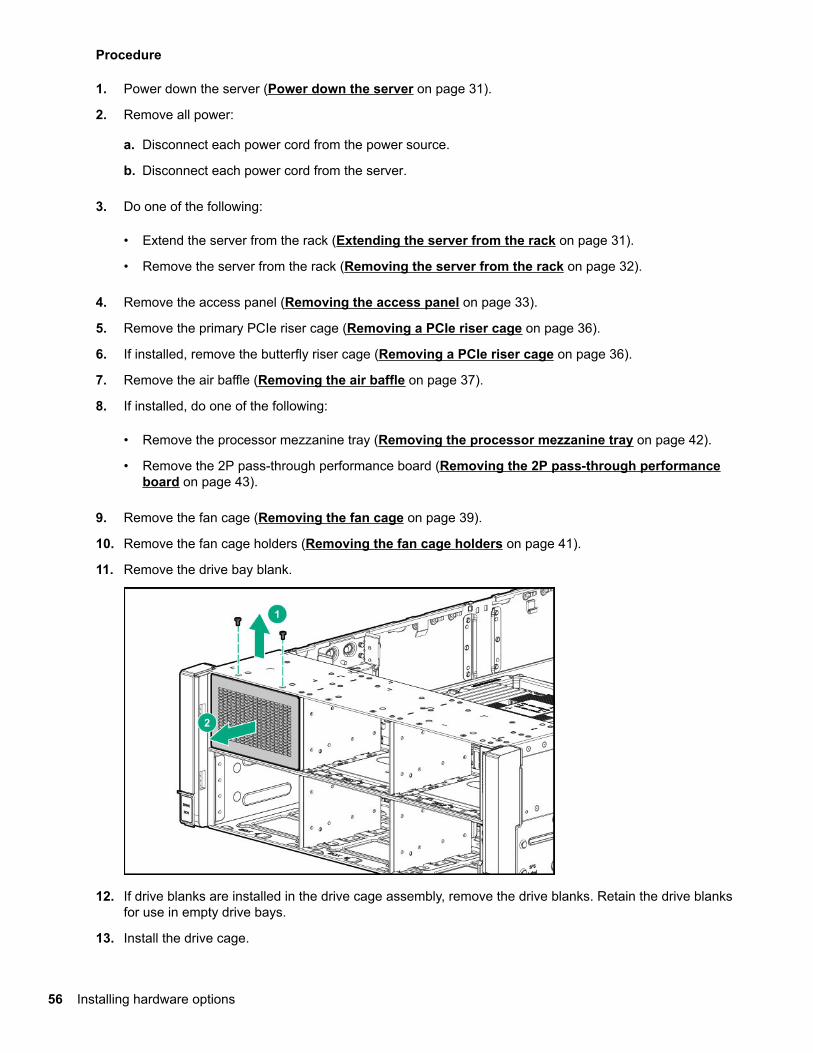
11. Remove the drive bay blank.
12. If drive blanks are installed in the drive cage assembly, remove the drive blanks. Retain the drive blanksfor use in empty drive bays.
13. Install the drive cage.
56 Installing hardware options
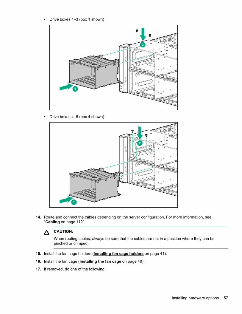
• Drive boxes 1–3 (box 1 shown)
• Drive boxes 4–6 (box 4 shown)
14. Route and connect the cables depending on the server configuration. For more information, see"Cabling on page 112".
CAUTION:
When routing cables, always be sure that the cables are not in a position where they can bepinched or crimped.
15. Install the fan cage holders (Installing fan cage holders on page 41).
16. Install the fan cage (Installing the fan cage on page 40).
17. If removed, do one of the following:
Installing hardware options 57
• Install the processor mezzanine tray (Installing a processor mezzanine tray on page 96).
• Install the 2P pass-through performance board (Installing the 2P pass-through performance boardon page 101).
18. Install the air baffle (Installing the air baffle on page 38).
CAUTION:
To avoid damaging the connectors, always install the air baffle into the server before installing theriser cages.
19. Install the primary PCIe riser cage (Installing the primary PCIe riser cage on page 35).
20. Install the butterfly PCIe riser cage (Installing a butterfly PCIe riser cage on page 76).
21. Install the access panel (Installing the access panel on page 34).
22. Install the server into the rack (Installing the server into the rack on page 50).
23. Connect each power cord to the server.
24. Connect each power cord to the power source.
25. Power up the server (Power up the server on page 31).
Installing an eight-bay NVMe SSD drive cageThe eight-bay NVMe SSD drive cage can be installed in drive boxes 1–3.
• A minimum of four NVMe drives can be installed in the drive cage.
• When installed in drive box 1, only four NVMe drives can be installed in the drive cage.
For more information on valid NVMe drive configurations and cabling, see "NVMe drive cable matrix onpage 114."
Prerequisites
Before installing this option, be sure that you have the following:
• T-10 Torx screwdriver
• The components included with the hardware option kit
Procedure
1. Power down the server (Power down the server on page 31).
2. Remove all power:
a. Disconnect each power cord from the power source.
b. Disconnect each power cord from the server.
3. Do one of the following:
58 Installing an eight-bay NVMe SSD drive cage
• Extend the server from the rack (Extending the server from the rack on page 31).
• Remove the server from the rack (Removing the server from the rack on page 32).
4. Remove the access panel (Removing the access panel on page 33).
5. Remove the primary PCIe riser cage (Removing a PCIe riser cage on page 36).
6. If installed, remove the butterfly riser cage (Removing a PCIe riser cage on page 36).
7. Remove the air baffle (Removing the air baffle on page 37).
8. If installed, do one of the following:
• Remove the processor mezzanine tray (Removing the processor mezzanine tray on page 42).
• Remove the 2P pass-through performance board (Removing the 2P pass-through performanceboard on page 43).
9. Remove the fan cage (Removing the fan cage on page 39).
10. Remove the fan cage holders (Removing the fan cage holders on page 41).
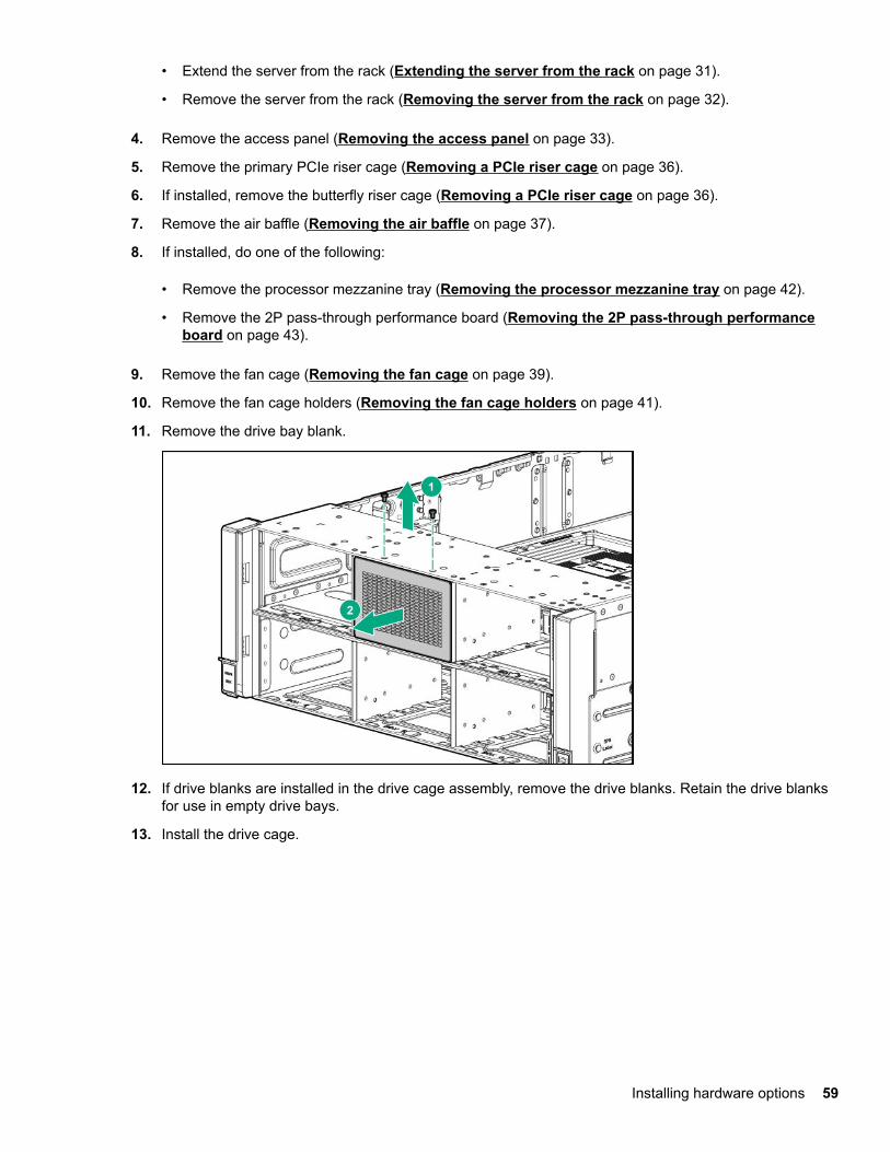
11. Remove the drive bay blank.
12. If drive blanks are installed in the drive cage assembly, remove the drive blanks. Retain the drive blanksfor use in empty drive bays.
13. Install the drive cage.
Installing hardware options 59
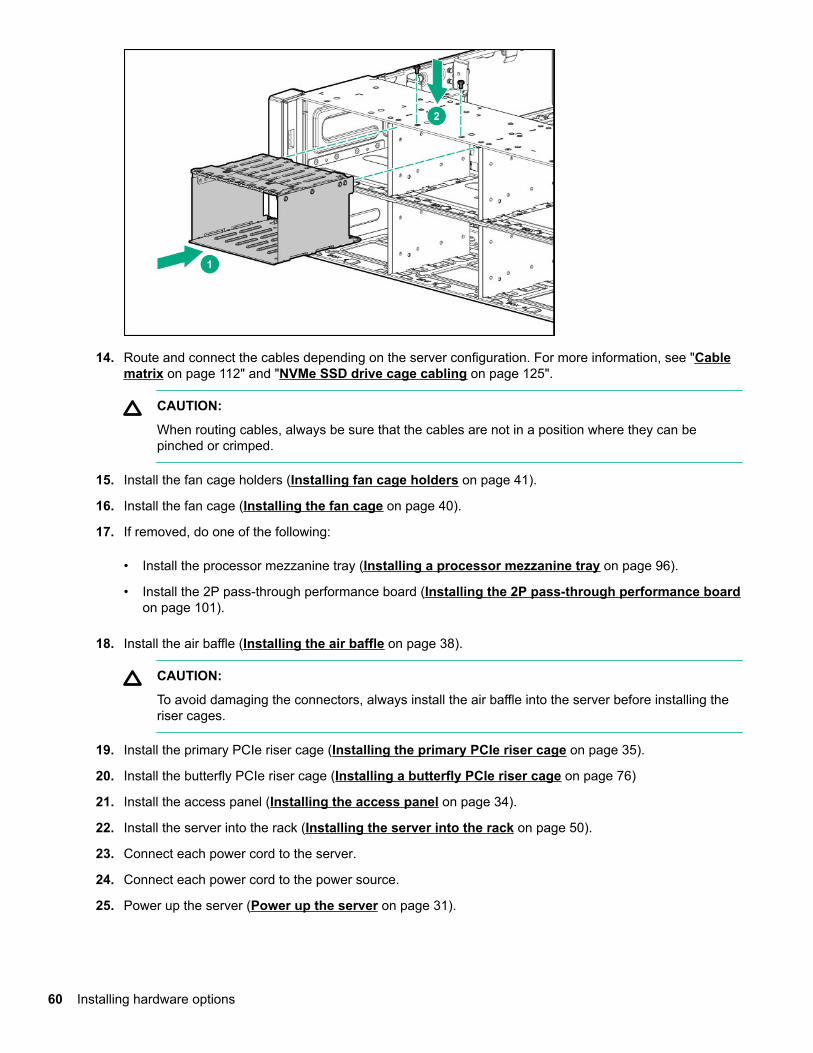
14. Route and connect the cables depending on the server configuration. For more information, see "Cablematrix on page 112" and "NVMe SSD drive cage cabling on page 125".
CAUTION:
When routing cables, always be sure that the cables are not in a position where they can bepinched or crimped.
15. Install the fan cage holders (Installing fan cage holders on page 41).
16. Install the fan cage (Installing the fan cage on page 40).
17. If removed, do one of the following:
• Install the processor mezzanine tray (Installing a processor mezzanine tray on page 96).
• Install the 2P pass-through performance board (Installing the 2P pass-through performance boardon page 101).
18. Install the air baffle (Installing the air baffle on page 38).
CAUTION:
To avoid damaging the connectors, always install the air baffle into the server before installing theriser cages.
19. Install the primary PCIe riser cage (Installing the primary PCIe riser cage on page 35).
20. Install the butterfly PCIe riser cage (Installing a butterfly PCIe riser cage on page 76)
21. Install the access panel (Installing the access panel on page 34).
22. Install the server into the rack (Installing the server into the rack on page 50).
23. Connect each power cord to the server.
24. Connect each power cord to the power source.
25. Power up the server (Power up the server on page 31).
60 Installing hardware options
Installing a six-bay SFF HDD/two-bay NVMe SSD cageThe two-bay NVME SSD/six-bay SFF HDD drive cage can be installed in the following drive boxes in theserver. For more information, see "Front panel components on page 7."
• Drive box 1
• Drive box 2
• Drive box 3
Prerequisites
Before installing this option, be sure that you have the following:
• T-10 Torx screwdriver
• The components included with the hardware option kit
Procedure
1. Power down the server (Power down the server on page 31).
2. Remove all power:
a. Disconnect each power cord from the power source.
b. Disconnect each power cord from the server.
3. Do one of the following:
• Extend the server from the rack (Extending the server from the rack on page 31).
• Remove the server from the rack (Removing the server from the rack on page 32).
4. Remove the access panel (Removing the access panel on page 33).
5. Remove the primary PCIe riser cage (Removing a PCIe riser cage on page 36).
6. If installed, remove the butterfly riser cage (Removing a PCIe riser cage on page 36).
7. Remove the air baffle (Removing the air baffle on page 37).
8. If installed, do one of the following:
• Remove the processor mezzanine tray (Removing the processor mezzanine tray on page 42).
• Remove the 2P pass-through performance board (Removing the 2P pass-through performanceboard on page 43).
9. Remove the fan cage (Removing the fan cage on page 39).
10. Remove the fan cage holders (Removing the fan cage holders on page 41).
11. Remove the drive bay blank.
Installing a six-bay SFF HDD/two-bay NVMe SSD cage 61
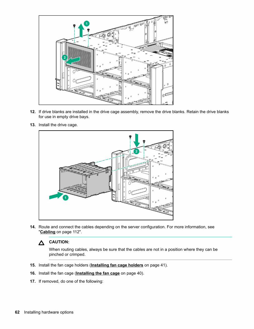
12. If drive blanks are installed in the drive cage assembly, remove the drive blanks. Retain the drive blanksfor use in empty drive bays.
13. Install the drive cage.
14. Route and connect the cables depending on the server configuration. For more information, see"Cabling on page 112".
CAUTION:
When routing cables, always be sure that the cables are not in a position where they can bepinched or crimped.
15. Install the fan cage holders (Installing fan cage holders on page 41).
16. Install the fan cage (Installing the fan cage on page 40).
17. If removed, do one of the following:
62 Installing hardware options
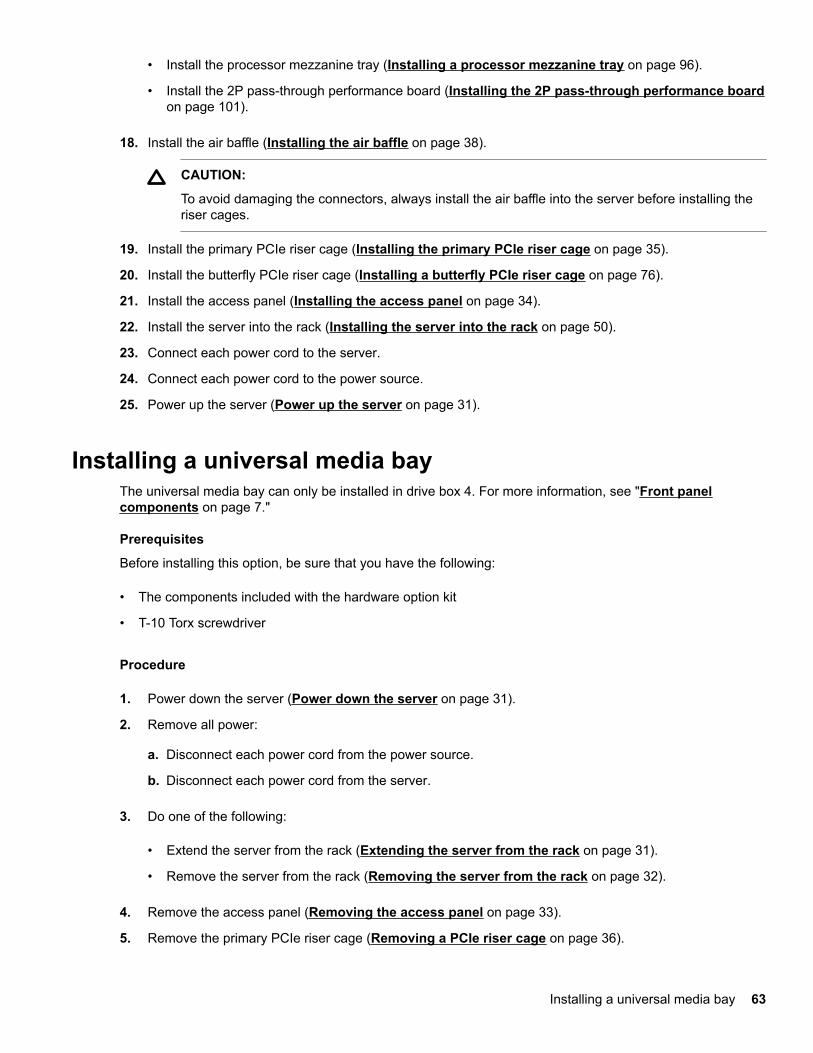
• Install the processor mezzanine tray (Installing a processor mezzanine tray on page 96).
• Install the 2P pass-through performance board (Installing the 2P pass-through performance boardon page 101).
18. Install the air baffle (Installing the air baffle on page 38).
CAUTION:
To avoid damaging the connectors, always install the air baffle into the server before installing theriser cages.
19. Install the primary PCIe riser cage (Installing the primary PCIe riser cage on page 35).
20. Install the butterfly PCIe riser cage (Installing a butterfly PCIe riser cage on page 76).
21. Install the access panel (Installing the access panel on page 34).
22. Install the server into the rack (Installing the server into the rack on page 50).
23. Connect each power cord to the server.
24. Connect each power cord to the power source.
25. Power up the server (Power up the server on page 31).
Installing a universal media bayThe universal media bay can only be installed in drive box 4. For more information, see "Front panelcomponents on page 7."
Prerequisites
Before installing this option, be sure that you have the following:
• The components included with the hardware option kit
• T-10 Torx screwdriver
Procedure
1. Power down the server (Power down the server on page 31).
2. Remove all power:
a. Disconnect each power cord from the power source.
b. Disconnect each power cord from the server.
3. Do one of the following:
• Extend the server from the rack (Extending the server from the rack on page 31).
• Remove the server from the rack (Removing the server from the rack on page 32).
4. Remove the access panel (Removing the access panel on page 33).
5. Remove the primary PCIe riser cage (Removing a PCIe riser cage on page 36).
Installing a universal media bay 63
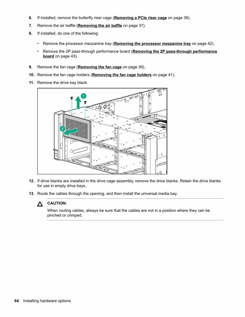
6. If installed, remove the butterfly riser cage (Removing a PCIe riser cage on page 36).
7. Remove the air baffle (Removing the air baffle on page 37).
8. If installed, do one of the following:
• Remove the processor mezzanine tray (Removing the processor mezzanine tray on page 42).
• Remove the 2P pass-through performance board (Removing the 2P pass-through performanceboard on page 43).
9. Remove the fan cage (Removing the fan cage on page 39).
10. Remove the fan cage holders (Removing the fan cage holders on page 41).
11. Remove the drive bay blank.
12. If drive blanks are installed in the drive cage assembly, remove the drive blanks. Retain the drive blanksfor use in empty drive bays.
13. Route the cables through the opening, and then install the universal media bay.
CAUTION:
When routing cables, always be sure that the cables are not in a position where they can bepinched or crimped.
64 Installing hardware options
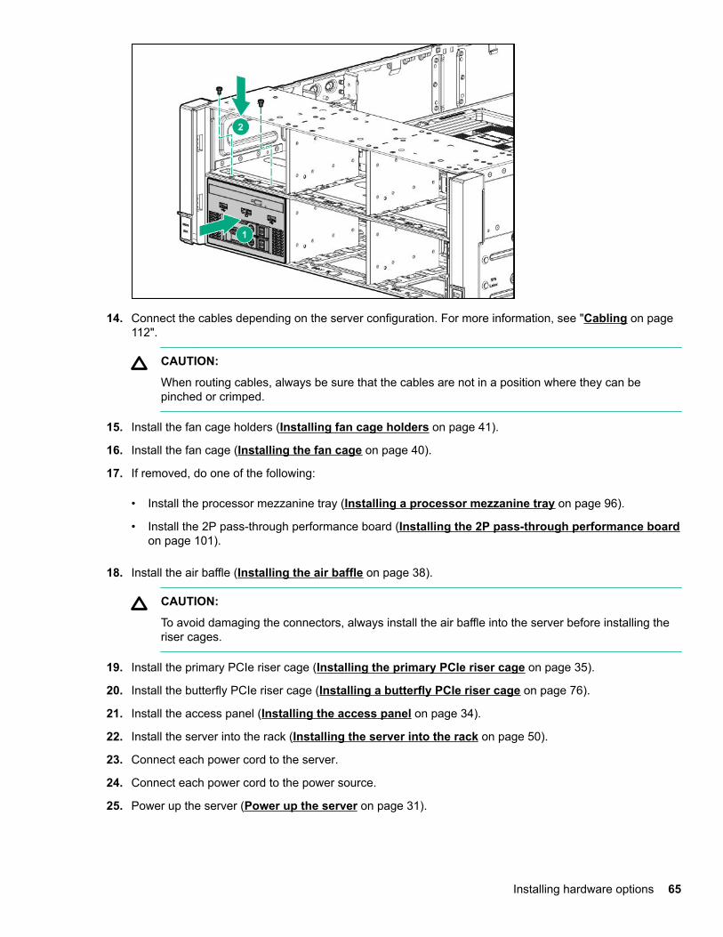
14. Connect the cables depending on the server configuration. For more information, see "Cabling on page112".
CAUTION:
When routing cables, always be sure that the cables are not in a position where they can bepinched or crimped.
15. Install the fan cage holders (Installing fan cage holders on page 41).
16. Install the fan cage (Installing the fan cage on page 40).
17. If removed, do one of the following:
• Install the processor mezzanine tray (Installing a processor mezzanine tray on page 96).
• Install the 2P pass-through performance board (Installing the 2P pass-through performance boardon page 101).
18. Install the air baffle (Installing the air baffle on page 38).
CAUTION:
To avoid damaging the connectors, always install the air baffle into the server before installing theriser cages.
19. Install the primary PCIe riser cage (Installing the primary PCIe riser cage on page 35).
20. Install the butterfly PCIe riser cage (Installing a butterfly PCIe riser cage on page 76).
21. Install the access panel (Installing the access panel on page 34).
22. Install the server into the rack (Installing the server into the rack on page 50).
23. Connect each power cord to the server.
24. Connect each power cord to the power source.
25. Power up the server (Power up the server on page 31).
Installing hardware options 65

Installing a two-bay SFF drive cagePrerequisites
Before installing this option, be sure that you have the following:
• T-10 Torx screwdriver
• The components included with the hardware option kit
The front bay installation requires a universal media bay to be installed.
Procedure
1. Power down the server (Power down the server on page 31).
2. Remove all power:
a. Disconnect each power cord from the power source.
b. Disconnect each power cord from the server.
3. Do one of the following:
• Extend the server from the rack (Extending the server from the rack on page 31).
• Remove the server from the rack (Removing the server from the rack on page 32).
4. Remove the access panel (Removing the access panel on page 33).
5. Remove the primary PCIe riser cage (Removing a PCIe riser cage on page 36).
6. If installed, remove the butterfly riser cage (Removing a PCIe riser cage on page 36).
7. Remove the air baffle (Removing the air baffle on page 37).
8. If installed, do one of the following:
• Remove the processor mezzanine tray (Removing the processor mezzanine tray on page 42).
• Remove the 2P pass-through performance board (Removing the 2P pass-through performanceboard on page 43).
9. Remove the fan cage (Removing the fan cage on page 39).
10. Remove the fan cage holders (Removing the fan cage holders on page 41).
11. Remove the drive bay blank.
66 Installing a two-bay SFF drive cage
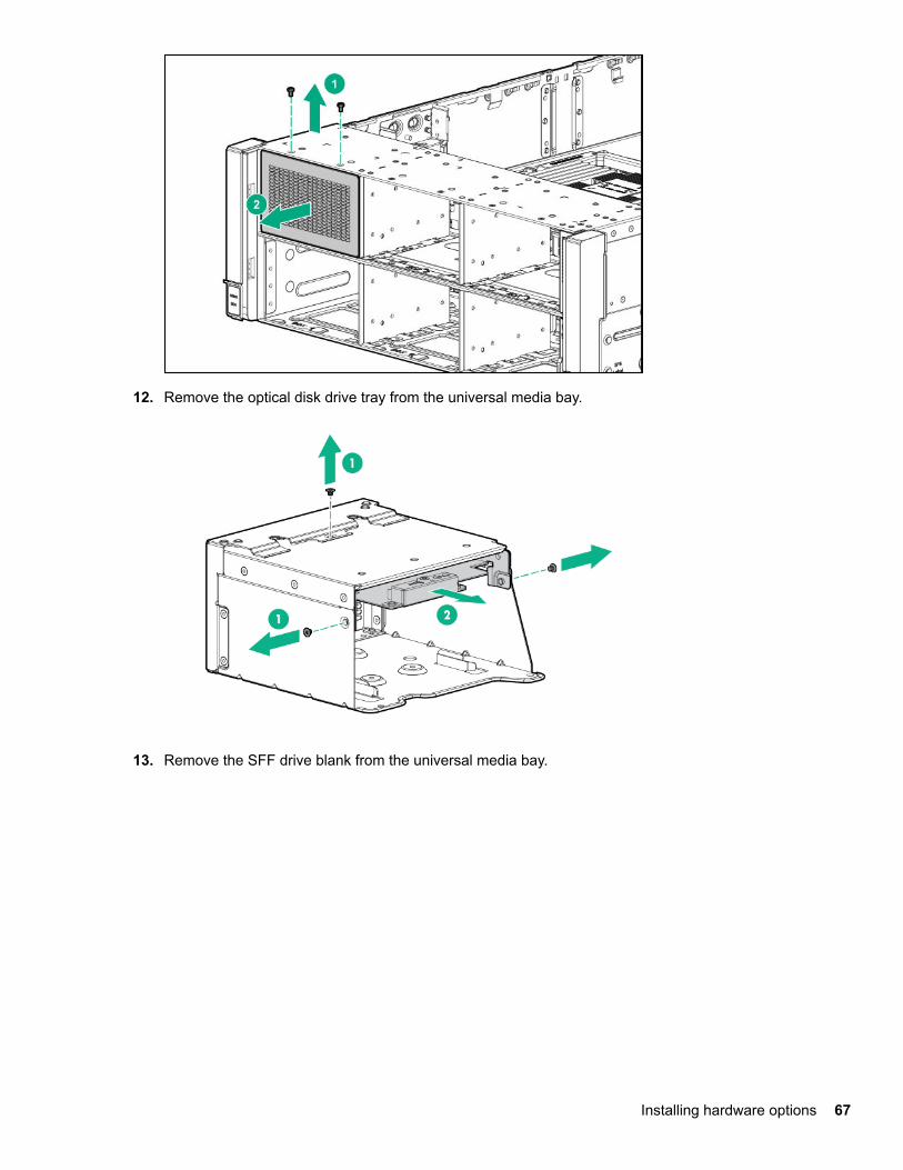
12. Remove the optical disk drive tray from the universal media bay.
13. Remove the SFF drive blank from the universal media bay.
Installing hardware options 67
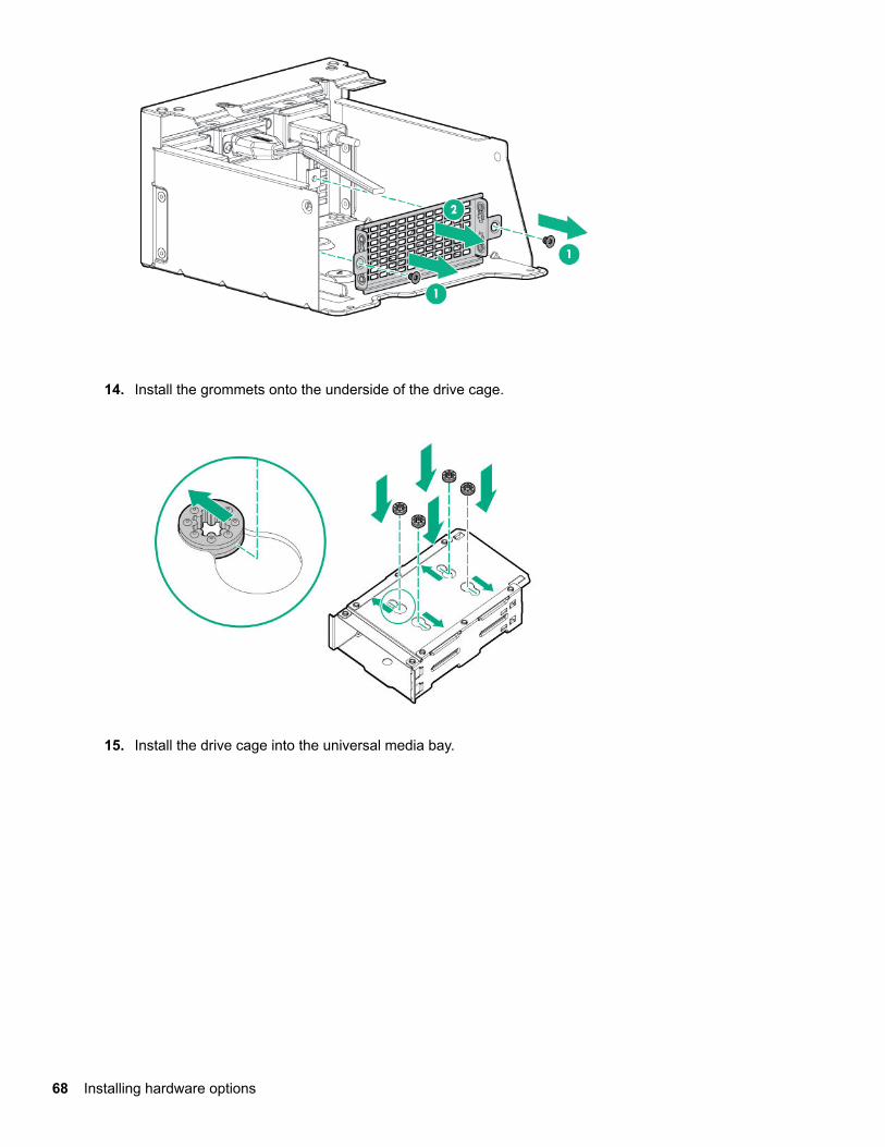
14. Install the grommets onto the underside of the drive cage.
15. Install the drive cage into the universal media bay.
68 Installing hardware options
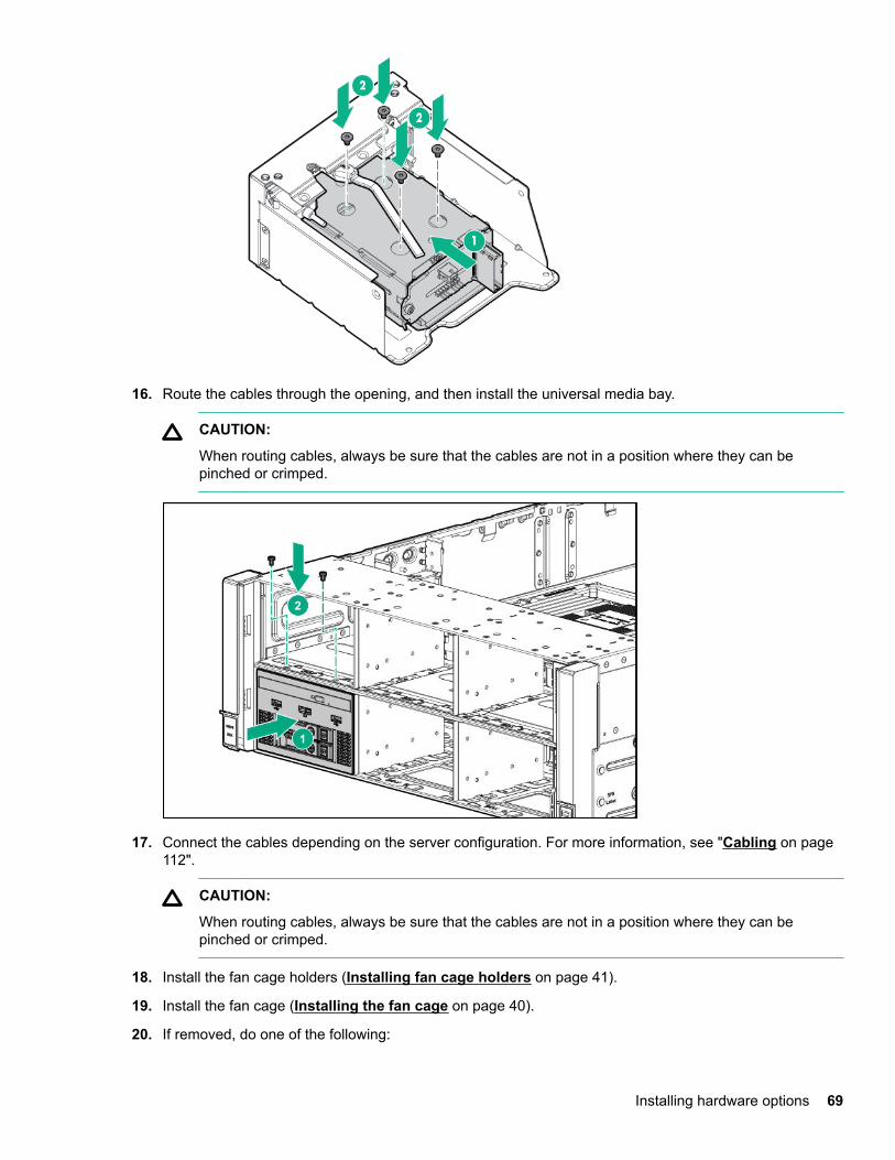
16. Route the cables through the opening, and then install the universal media bay.
CAUTION:
When routing cables, always be sure that the cables are not in a position where they can bepinched or crimped.
17. Connect the cables depending on the server configuration. For more information, see "Cabling on page112".
CAUTION:
When routing cables, always be sure that the cables are not in a position where they can bepinched or crimped.
18. Install the fan cage holders (Installing fan cage holders on page 41).
19. Install the fan cage (Installing the fan cage on page 40).
20. If removed, do one of the following:
Installing hardware options 69
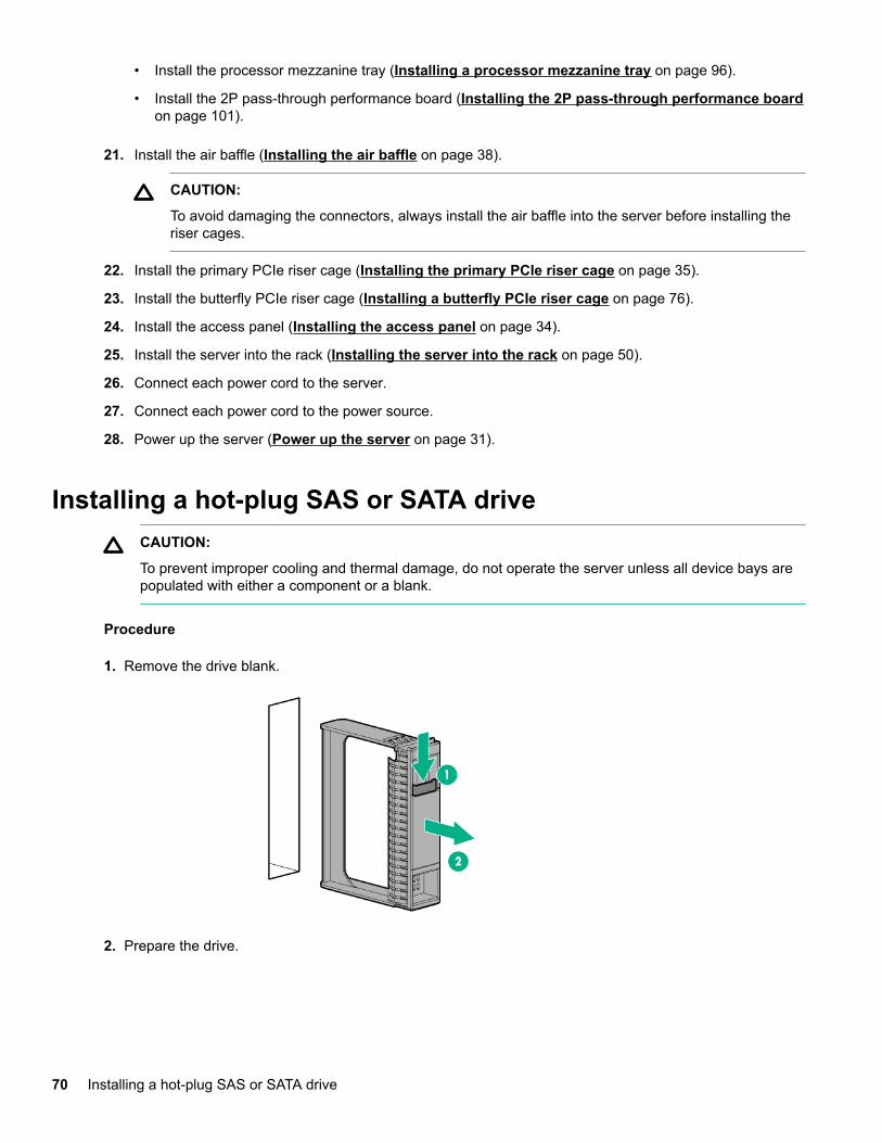
• Install the processor mezzanine tray (Installing a processor mezzanine tray on page 96).
• Install the 2P pass-through performance board (Installing the 2P pass-through performance boardon page 101).
21. Install the air baffle (Installing the air baffle on page 38).
CAUTION:
To avoid damaging the connectors, always install the air baffle into the server before installing theriser cages.
22. Install the primary PCIe riser cage (Installing the primary PCIe riser cage on page 35).
23. Install the butterfly PCIe riser cage (Installing a butterfly PCIe riser cage on page 76).
24. Install the access panel (Installing the access panel on page 34).
25. Install the server into the rack (Installing the server into the rack on page 50).
26. Connect each power cord to the server.
27. Connect each power cord to the power source.
28. Power up the server (Power up the server on page 31).
Installing a hot-plug SAS or SATA driveCAUTION:
To prevent improper cooling and thermal damage, do not operate the server unless all device bays arepopulated with either a component or a blank.
Procedure
1. Remove the drive blank.
2. Prepare the drive.
70 Installing a hot-plug SAS or SATA drive
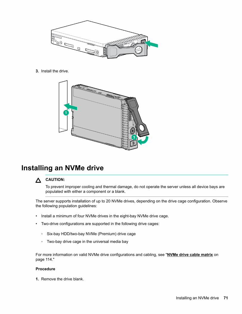
3. Install the drive.
Installing an NVMe driveCAUTION:
To prevent improper cooling and thermal damage, do not operate the server unless all device bays arepopulated with either a component or a blank.
The server supports installation of up to 20 NVMe drives, depending on the drive cage configuration. Observethe following population guidelines:
• Install a minimum of four NVMe drives in the eight-bay NVMe drive cage.
• Two-drive configurations are supported in the following drive cages:
◦ Six-bay HDD/two-bay NVMe (Premium) drive cage
◦ Two-bay drive cage in the universal media bay
For more information on valid NVMe drive configurations and cabling, see "NVMe drive cable matrix onpage 114."
Procedure
1. Remove the drive blank.
Installing an NVMe drive 71
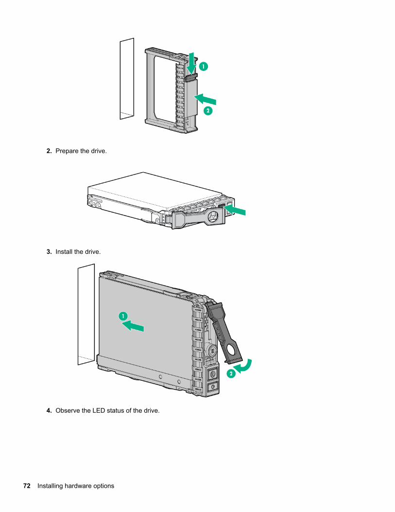
2. Prepare the drive.
3. Install the drive.
4. Observe the LED status of the drive.
72 Installing hardware options
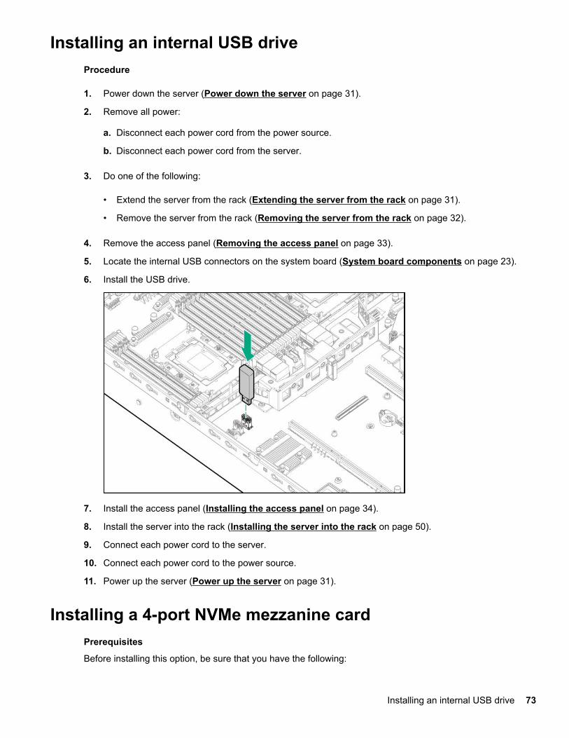
Installing an internal USB driveProcedure
1. Power down the server (Power down the server on page 31).
2. Remove all power:
a. Disconnect each power cord from the power source.
b. Disconnect each power cord from the server.
3. Do one of the following:
• Extend the server from the rack (Extending the server from the rack on page 31).
• Remove the server from the rack (Removing the server from the rack on page 32).
4. Remove the access panel (Removing the access panel on page 33).
5. Locate the internal USB connectors on the system board (System board components on page 23).
6. Install the USB drive.
7. Install the access panel (Installing the access panel on page 34).
8. Install the server into the rack (Installing the server into the rack on page 50).
9. Connect each power cord to the server.
10. Connect each power cord to the power source.
11. Power up the server (Power up the server on page 31).
Installing a 4-port NVMe mezzanine cardPrerequisites
Before installing this option, be sure that you have the following:
Installing an internal USB drive 73
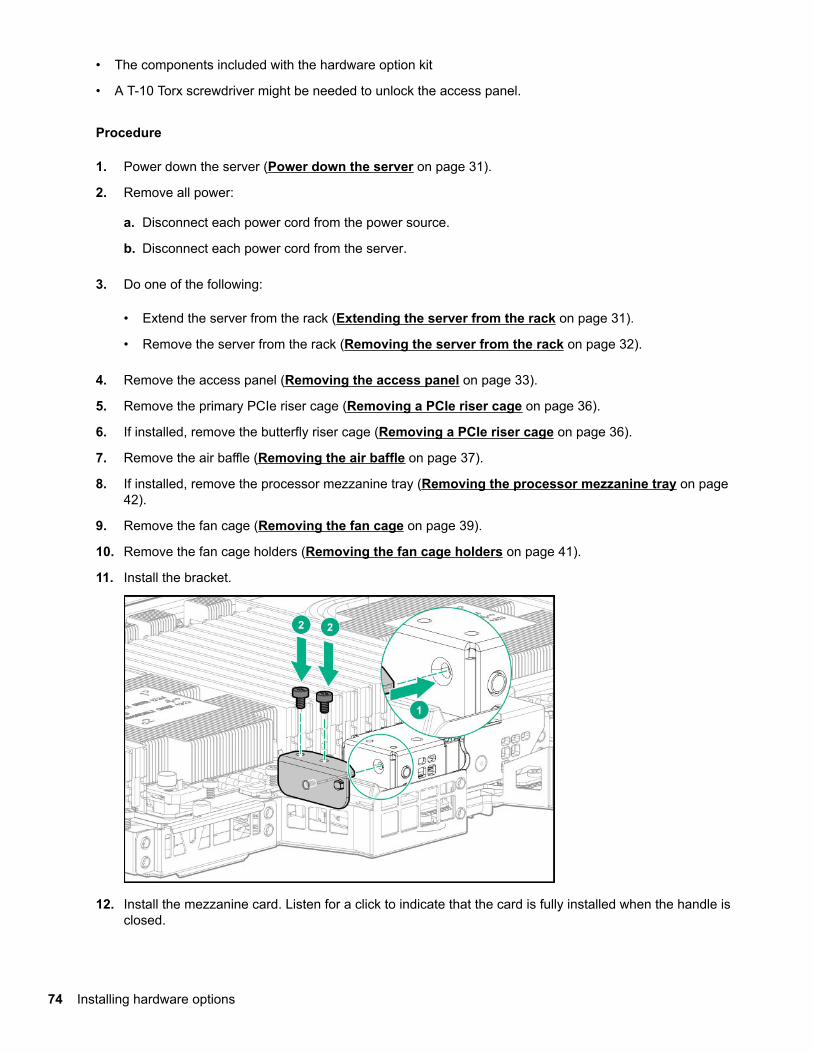
• The components included with the hardware option kit
• A T-10 Torx screwdriver might be needed to unlock the access panel.
Procedure
1. Power down the server (Power down the server on page 31).
2. Remove all power:
a. Disconnect each power cord from the power source.
b. Disconnect each power cord from the server.
3. Do one of the following:
• Extend the server from the rack (Extending the server from the rack on page 31).
• Remove the server from the rack (Removing the server from the rack on page 32).
4. Remove the access panel (Removing the access panel on page 33).
5. Remove the primary PCIe riser cage (Removing a PCIe riser cage on page 36).
6. If installed, remove the butterfly riser cage (Removing a PCIe riser cage on page 36).
7. Remove the air baffle (Removing the air baffle on page 37).
8. If installed, remove the processor mezzanine tray (Removing the processor mezzanine tray on page42).
9. Remove the fan cage (Removing the fan cage on page 39).
10. Remove the fan cage holders (Removing the fan cage holders on page 41).
11. Install the bracket.
12. Install the mezzanine card. Listen for a click to indicate that the card is fully installed when the handle isclosed.
74 Installing hardware options
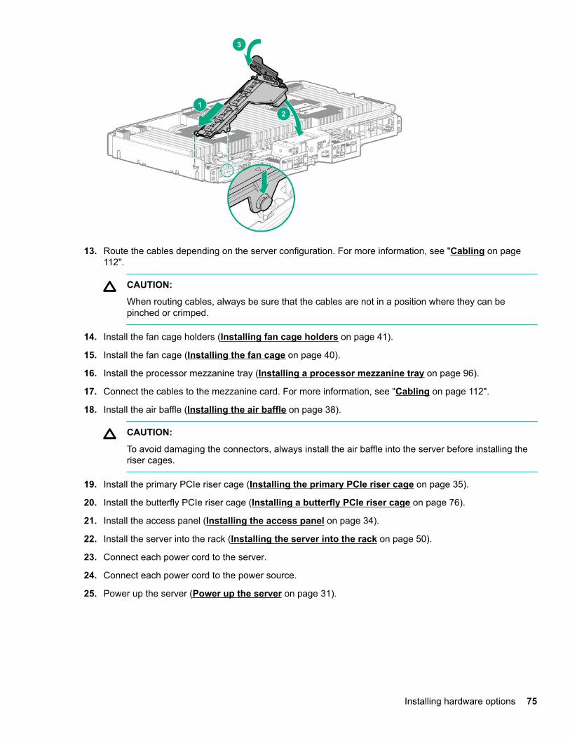
13. Route the cables depending on the server configuration. For more information, see "Cabling on page112".
CAUTION:
When routing cables, always be sure that the cables are not in a position where they can bepinched or crimped.
14. Install the fan cage holders (Installing fan cage holders on page 41).
15. Install the fan cage (Installing the fan cage on page 40).
16. Install the processor mezzanine tray (Installing a processor mezzanine tray on page 96).
17. Connect the cables to the mezzanine card. For more information, see "Cabling on page 112".
18. Install the air baffle (Installing the air baffle on page 38).
CAUTION:
To avoid damaging the connectors, always install the air baffle into the server before installing theriser cages.
19. Install the primary PCIe riser cage (Installing the primary PCIe riser cage on page 35).
20. Install the butterfly PCIe riser cage (Installing a butterfly PCIe riser cage on page 76).
21. Install the access panel (Installing the access panel on page 34).
22. Install the server into the rack (Installing the server into the rack on page 50).
23. Connect each power cord to the server.
24. Connect each power cord to the power source.
25. Power up the server (Power up the server on page 31).
Installing hardware options 75
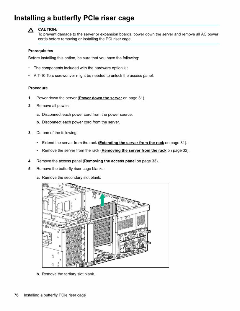
Installing a butterfly PCIe riser cageCAUTION:To prevent damage to the server or expansion boards, power down the server and remove all AC powercords before removing or installing the PCI riser cage.
Prerequisites
Before installing this option, be sure that you have the following:
• The components included with the hardware option kit
• A T-10 Torx screwdriver might be needed to unlock the access panel.
Procedure
1. Power down the server (Power down the server on page 31).
2. Remove all power:
a. Disconnect each power cord from the power source.
b. Disconnect each power cord from the server.
3. Do one of the following:
• Extend the server from the rack (Extending the server from the rack on page 31).
• Remove the server from the rack (Removing the server from the rack on page 32).
4. Remove the access panel (Removing the access panel on page 33).
5. Remove the butterfly riser cage blanks.
a. Remove the secondary slot blank.
b. Remove the tertiary slot blank.
76 Installing a butterfly PCIe riser cage
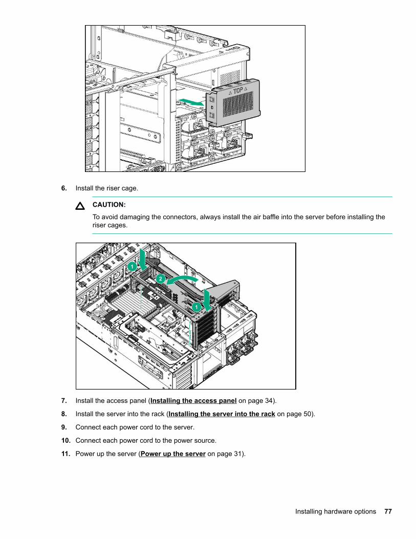
6. Install the riser cage.
CAUTION:
To avoid damaging the connectors, always install the air baffle into the server before installing theriser cages.
7. Install the access panel (Installing the access panel on page 34).
8. Install the server into the rack (Installing the server into the rack on page 50).
9. Connect each power cord to the server.
10. Connect each power cord to the power source.
11. Power up the server (Power up the server on page 31).
Installing hardware options 77
Installing riser board optionsThe server supports two PCIe riser cages that can be configured with different riser boards.
Primary PCIe riser cage
The primary PCIe riser cage supports installation of the following riser boards:
• Six-slot riser board with four x8, two x16, and two x8 Slimline NVMe connections.
• Seven-slot riser board with four x8 and three x16 connections.
• Four-port riser board with four x8 Slimline NVMe connections in the secondary PCIe slot.
Butterfly PCIe riser cage (Secondary PCIe slot)
The butterfly PCIe riser cage supports installation of the following riser boards in the secondary PCIe slot:
• Six-slot riser board with four x8, two x16, and two x8 Slimline NVMe connections in the secondary PCIeslot.
• Seven-slot riser board with four x8 and three x16 connections in the secondary PCIe slot.
Butterfly PCIe riser cage (Tertiary PCIe slot)
The butterfly PCIe riser cage supports installation of a two-slot riser board with two x8 connections in thetertiary PCIe slot.
Installing a riser board into the primary PCIe riser cage
Prerequisites
Before installing this option, be sure that you have the following:
• T-10 Torx screwdriver
• The components included with the hardware option kit
Procedure
1. Power down the server (Power down the server on page 31).
2. Remove all power:
a. Disconnect each power cord from the power source.
b. Disconnect each power cord from the server.
3. Do one of the following:
• Extend the server from the rack (Extending the server from the rack on page 31).
• Remove the server from the rack (Removing the server from the rack on page 32).
4. Remove the access panel (Removing the access panel on page 33).
5. Disconnect all cables attached to the expansion boards in the PCIe riser cage.
78 Installing riser board options
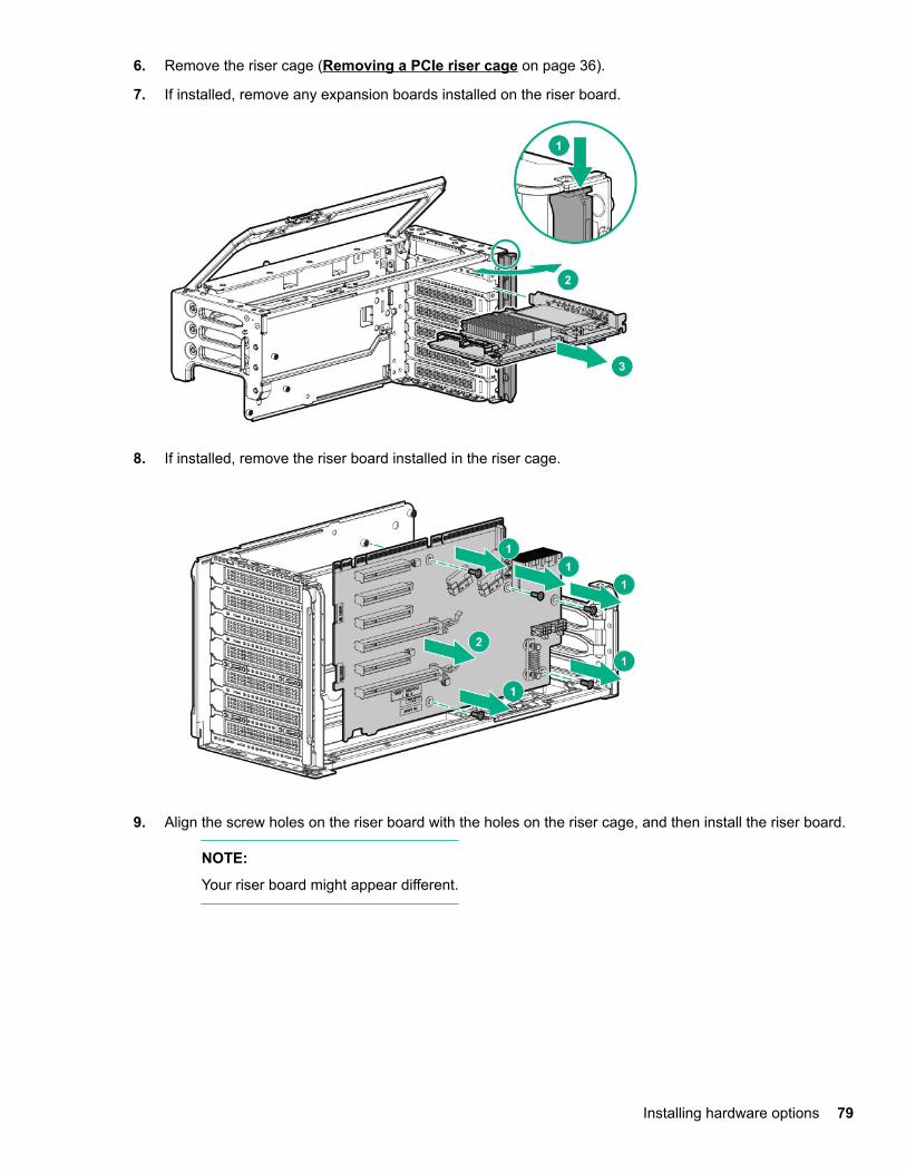
6. Remove the riser cage (Removing a PCIe riser cage on page 36).
7. If installed, remove any expansion boards installed on the riser board.
8. If installed, remove the riser board installed in the riser cage.
9. Align the screw holes on the riser board with the holes on the riser cage, and then install the riser board.
NOTE:
Your riser board might appear different.
Installing hardware options 79
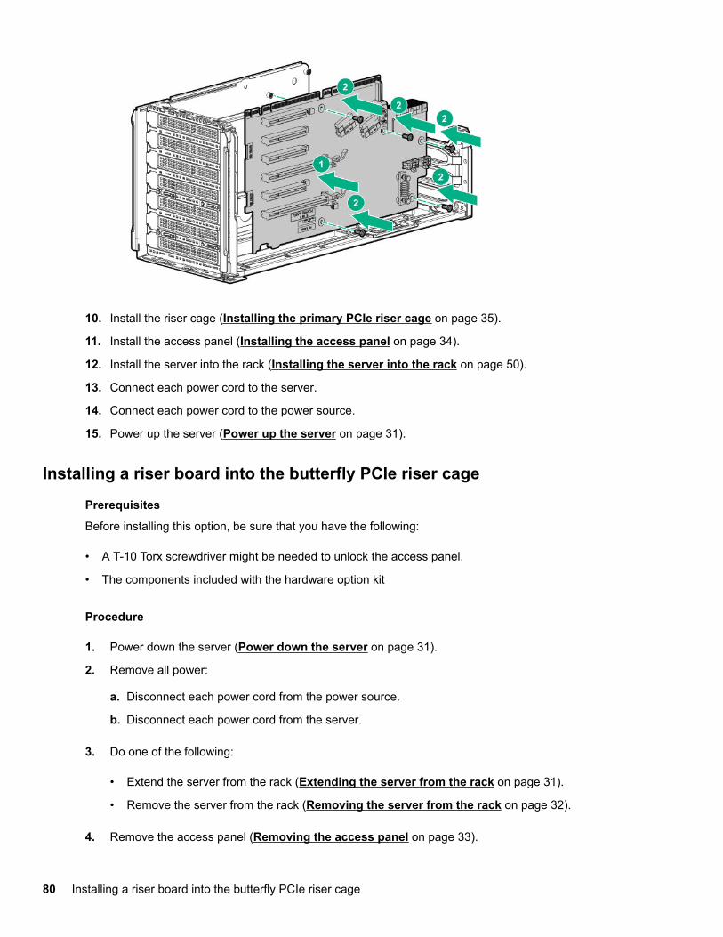
10. Install the riser cage (Installing the primary PCIe riser cage on page 35).
11. Install the access panel (Installing the access panel on page 34).
12. Install the server into the rack (Installing the server into the rack on page 50).
13. Connect each power cord to the server.
14. Connect each power cord to the power source.
15. Power up the server (Power up the server on page 31).
Installing a riser board into the butterfly PCIe riser cage
Prerequisites
Before installing this option, be sure that you have the following:
• A T-10 Torx screwdriver might be needed to unlock the access panel.
• The components included with the hardware option kit
Procedure
1. Power down the server (Power down the server on page 31).
2. Remove all power:
a. Disconnect each power cord from the power source.
b. Disconnect each power cord from the server.
3. Do one of the following:
• Extend the server from the rack (Extending the server from the rack on page 31).
• Remove the server from the rack (Removing the server from the rack on page 32).
4. Remove the access panel (Removing the access panel on page 33).
80 Installing a riser board into the butterfly PCIe riser cage
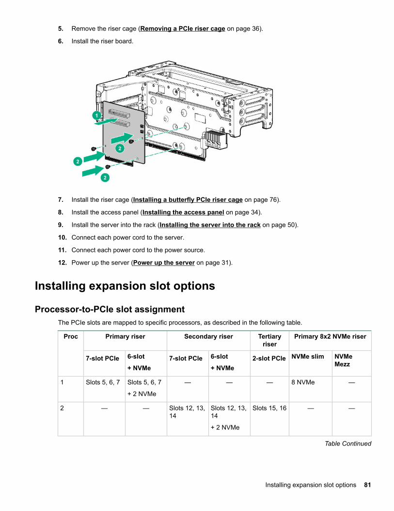
5. Remove the riser cage (Removing a PCIe riser cage on page 36).
6. Install the riser board.
7. Install the riser cage (Installing a butterfly PCIe riser cage on page 76).
8. Install the access panel (Installing the access panel on page 34).
9. Install the server into the rack (Installing the server into the rack on page 50).
10. Connect each power cord to the server.
11. Connect each power cord to the power source.
12. Power up the server (Power up the server on page 31).
Installing expansion slot options
Processor-to-PCIe slot assignmentThe PCIe slots are mapped to specific processors, as described in the following table.
Proc Primary riser Secondary riser Tertiaryriser
Primary 8x2 NVMe riser
7-slot PCIe 6-slot
+ NVMe7-slot PCIe 6-slot
+ NVMe2-slot PCIe NVMe slim NVMe
Mezz
1 Slots 5, 6, 7 Slots 5, 6, 7
+ 2 NVMe
— — — 8 NVMe —
2 — — Slots 12, 13,14
Slots 12, 13,14
+ 2 NVMe
Slots 15, 16 — —
Table Continued
Installing expansion slot options 81
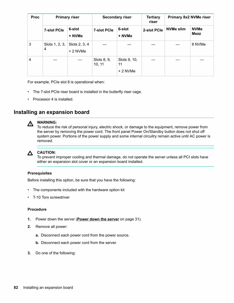
Proc Primary riser Secondary riser Tertiaryriser
Primary 8x2 NVMe riser
7-slot PCIe 6-slot
+ NVMe7-slot PCIe 6-slot
+ NVMe2-slot PCIe NVMe slim NVMe
Mezz
3 Slots 1, 2, 3,4
Slots 2, 3, 4
+ 2 NVMe
— — — — 8 NVMe
4 — — Slots 8, 9,10, 11
Slots 9, 10,11
+ 2 NVMe
— — —
For example, PCIe slot 8 is operational when:
• The 7-slot PCIe riser board is installed in the butterfly riser cage.
• Processor 4 is installed.
Installing an expansion board
WARNING:To reduce the risk of personal injury, electric shock, or damage to the equipment, remove power fromthe server by removing the power cord. The front panel Power On/Standby button does not shut offsystem power. Portions of the power supply and some internal circuitry remain active until AC power isremoved.
CAUTION:To prevent improper cooling and thermal damage, do not operate the server unless all PCI slots haveeither an expansion slot cover or an expansion board installed.
Prerequisites
Before installing this option, be sure that you have the following:
• The components included with the hardware option kit
• T-10 Torx screwdriver
Procedure
1. Power down the server (Power down the server on page 31).
2. Remove all power:
a. Disconnect each power cord from the power source.
b. Disconnect each power cord from the server.
3. Do one of the following:
82 Installing an expansion board
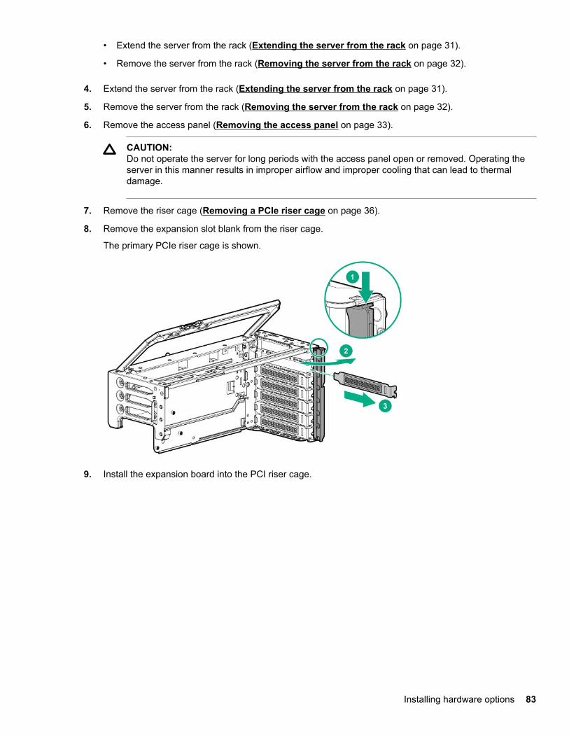
• Extend the server from the rack (Extending the server from the rack on page 31).
• Remove the server from the rack (Removing the server from the rack on page 32).
4. Extend the server from the rack (Extending the server from the rack on page 31).
5. Remove the server from the rack (Removing the server from the rack on page 32).
6. Remove the access panel (Removing the access panel on page 33).
CAUTION:Do not operate the server for long periods with the access panel open or removed. Operating theserver in this manner results in improper airflow and improper cooling that can lead to thermaldamage.
7. Remove the riser cage (Removing a PCIe riser cage on page 36).
8. Remove the expansion slot blank from the riser cage.
The primary PCIe riser cage is shown.
9. Install the expansion board into the PCI riser cage.
Installing hardware options 83
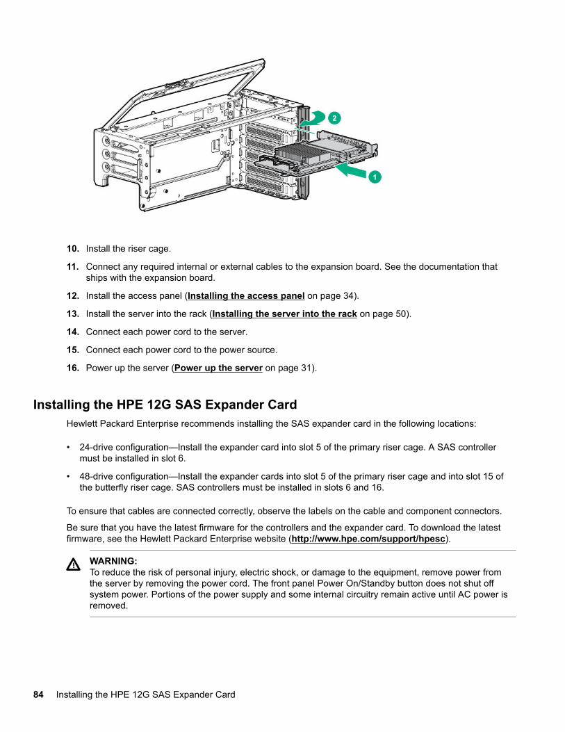
10. Install the riser cage.
11. Connect any required internal or external cables to the expansion board. See the documentation thatships with the expansion board.
12. Install the access panel (Installing the access panel on page 34).
13. Install the server into the rack (Installing the server into the rack on page 50).
14. Connect each power cord to the server.
15. Connect each power cord to the power source.
16. Power up the server (Power up the server on page 31).
Installing the HPE 12G SAS Expander CardHewlett Packard Enterprise recommends installing the SAS expander card in the following locations:
• 24-drive configuration—Install the expander card into slot 5 of the primary riser cage. A SAS controllermust be installed in slot 6.
• 48-drive configuration—Install the expander cards into slot 5 of the primary riser cage and into slot 15 ofthe butterfly riser cage. SAS controllers must be installed in slots 6 and 16.
To ensure that cables are connected correctly, observe the labels on the cable and component connectors.
Be sure that you have the latest firmware for the controllers and the expander card. To download the latestfirmware, see the Hewlett Packard Enterprise website (http://www.hpe.com/support/hpesc).
WARNING:To reduce the risk of personal injury, electric shock, or damage to the equipment, remove power fromthe server by removing the power cord. The front panel Power On/Standby button does not shut offsystem power. Portions of the power supply and some internal circuitry remain active until AC power isremoved.
84 Installing the HPE 12G SAS Expander Card
CAUTION:To prevent improper cooling and thermal damage, do not operate the server unless all PCI slots haveeither an expansion slot cover or an expansion board installed.
Prerequisites
• The components included with the hardware option kit
• Cables for each drive box
• A SAS controller for each expander
Procedure
1. Power down the server (Power down the server on page 31).
2. Remove all power:
a. Disconnect each power cord from the power source.
b. Disconnect each power cord from the server.
3. Do one of the following:
• Extend the server from the rack (Extending the server from the rack on page 31).
• Remove the server from the rack (Removing the server from the rack on page 32).
4. Extend the server from the rack (Extending the server from the rack on page 31).
5. Remove the server from the rack (Removing the server from the rack on page 32).
6. Remove the access panel (Removing the access panel on page 33).
CAUTION:Do not operate the server for long periods with the access panel open or removed. Operating theserver in this manner results in improper airflow and improper cooling that can lead to thermaldamage.
7. Remove the riser cage (Removing a PCIe riser cage on page 36).
8. Remove the expansion slot blank from slot 5 (primary riser cage) or slot 15 (butterfly riser cage).
The primary PCIe riser cage is shown.
Installing hardware options 85
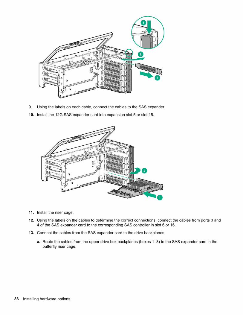
9. Using the labels on each cable, connect the cables to the SAS expander.
10. Install the 12G SAS expander card into expansion slot 5 or slot 15.
11. Install the riser cage.
12. Using the labels on the cables to determine the correct connections, connect the cables from ports 3 and4 of the SAS expander card to the corresponding SAS controller in slot 6 or 16.
13. Connect the cables from the SAS expander card to the drive backplanes.
a. Route the cables from the upper drive box backplanes (boxes 1–3) to the SAS expander card in thebutterfly riser cage.
86 Installing hardware options
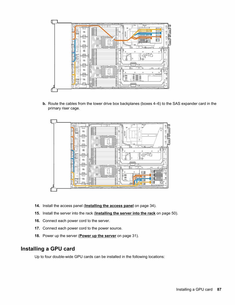
b. Route the cables from the lower drive box backplanes (boxes 4–6) to the SAS expander card in theprimary riser cage.
14. Install the access panel (Installing the access panel on page 34).
15. Install the server into the rack (Installing the server into the rack on page 50).
16. Connect each power cord to the server.
17. Connect each power cord to the power source.
18. Power up the server (Power up the server on page 31).
Installing a GPU cardUp to four double-wide GPU cards can be installed in the following locations:
Installing a GPU card 87
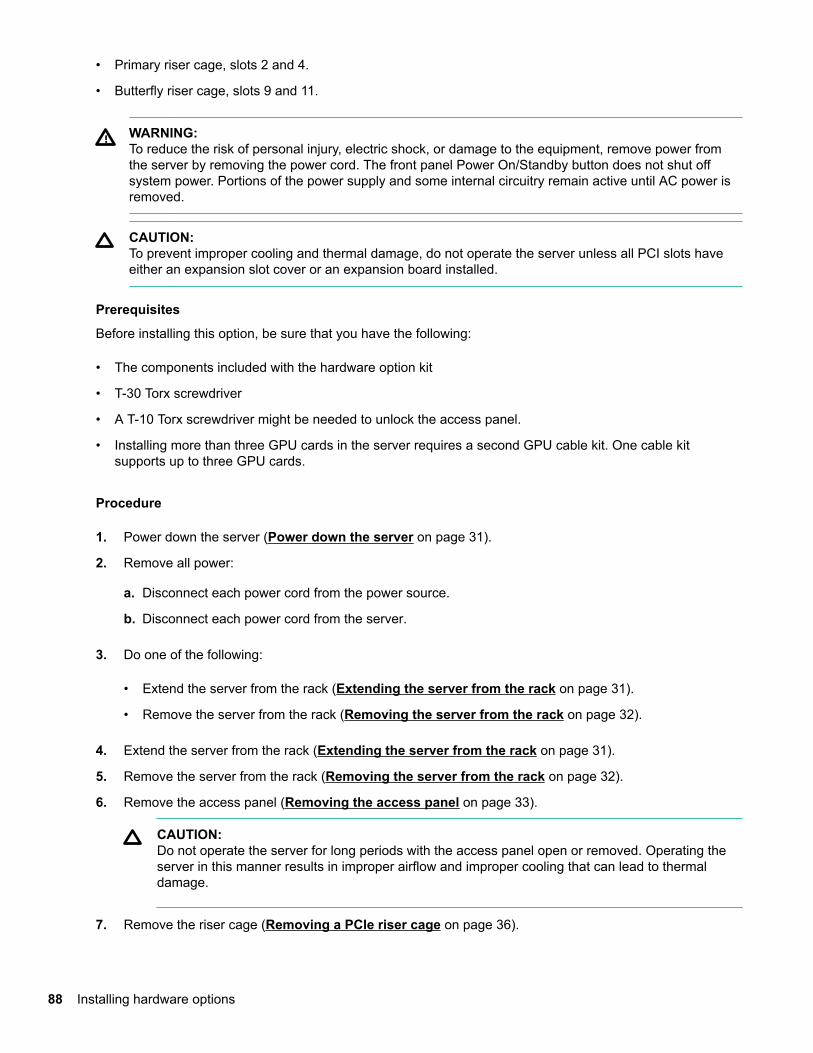
• Primary riser cage, slots 2 and 4.
• Butterfly riser cage, slots 9 and 11.
WARNING:To reduce the risk of personal injury, electric shock, or damage to the equipment, remove power fromthe server by removing the power cord. The front panel Power On/Standby button does not shut offsystem power. Portions of the power supply and some internal circuitry remain active until AC power isremoved.
CAUTION:To prevent improper cooling and thermal damage, do not operate the server unless all PCI slots haveeither an expansion slot cover or an expansion board installed.
Prerequisites
Before installing this option, be sure that you have the following:
• The components included with the hardware option kit
• T-30 Torx screwdriver
• A T-10 Torx screwdriver might be needed to unlock the access panel.
• Installing more than three GPU cards in the server requires a second GPU cable kit. One cable kitsupports up to three GPU cards.
Procedure
1. Power down the server (Power down the server on page 31).
2. Remove all power:
a. Disconnect each power cord from the power source.
b. Disconnect each power cord from the server.
3. Do one of the following:
• Extend the server from the rack (Extending the server from the rack on page 31).
• Remove the server from the rack (Removing the server from the rack on page 32).
4. Extend the server from the rack (Extending the server from the rack on page 31).
5. Remove the server from the rack (Removing the server from the rack on page 32).
6. Remove the access panel (Removing the access panel on page 33).
CAUTION:Do not operate the server for long periods with the access panel open or removed. Operating theserver in this manner results in improper airflow and improper cooling that can lead to thermaldamage.
7. Remove the riser cage (Removing a PCIe riser cage on page 36).
88 Installing hardware options
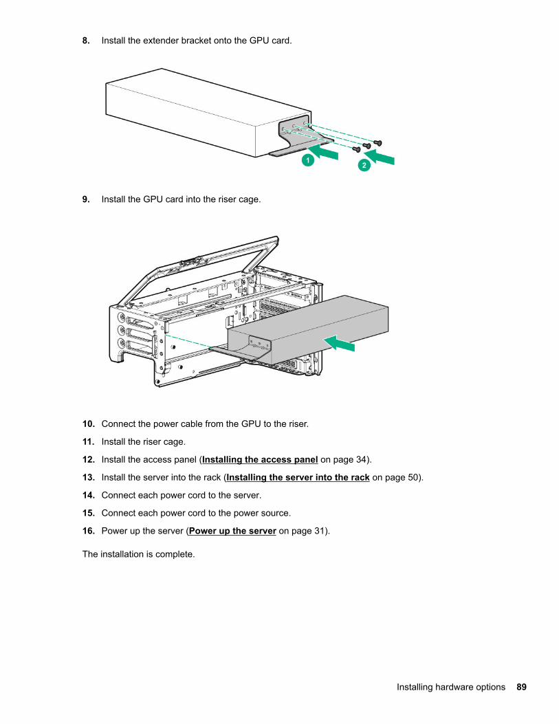
8. Install the extender bracket onto the GPU card.
9. Install the GPU card into the riser cage.
10. Connect the power cable from the GPU to the riser.
11. Install the riser cage.
12. Install the access panel (Installing the access panel on page 34).
13. Install the server into the rack (Installing the server into the rack on page 50).
14. Connect each power cord to the server.
15. Connect each power cord to the power source.
16. Power up the server (Power up the server on page 31).
The installation is complete.
Installing hardware options 89
Installing an expansion board
WARNING:To reduce the risk of personal injury, electric shock, or damage to the equipment, remove power fromthe server by removing the power cord. The front panel Power On/Standby button does not shut offsystem power. Portions of the power supply and some internal circuitry remain active until AC power isremoved.
CAUTION:To prevent improper cooling and thermal damage, do not operate the server unless all PCI slots haveeither an expansion slot cover or an expansion board installed.
Prerequisites
Before installing this option, be sure that you have the following:
• The components included with the hardware option kit
• T-10 Torx screwdriver
Procedure
1. Back up all server data.
2. Power down the server (Power down the server on page 31).
3. Remove all power:
a. Disconnect each power cord from the power source.
b. Disconnect each power cord from the server.
4. Do one of the following:
• Extend the server from the rack (Extending the server from the rack on page 31).
• Remove the server from the rack (Removing the server from the rack on page 32).
5. Extend the server from the rack (Extending the server from the rack on page 31).
6. Remove the server from the rack (Removing the server from the rack on page 32).
7. Remove the access panel (Removing the access panel on page 33).
CAUTION:Do not operate the server for long periods with the access panel open or removed. Operating theserver in this manner results in improper airflow and improper cooling that can lead to thermaldamage.
8. Remove the riser cage (Removing a PCIe riser cage on page 36).
9. Remove the expansion slot blank from the riser cage.
The primary PCIe riser cage is shown.
90 Installing an expansion board
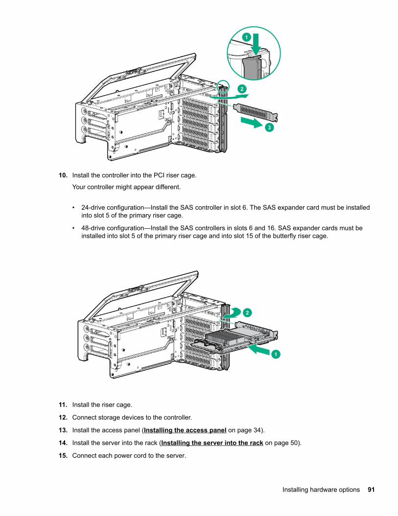
10. Install the controller into the PCI riser cage.
Your controller might appear different.
• 24-drive configuration—Install the SAS controller in slot 6. The SAS expander card must be installedinto slot 5 of the primary riser cage.
• 48-drive configuration—Install the SAS controllers in slots 6 and 16. SAS expander cards must beinstalled into slot 5 of the primary riser cage and into slot 15 of the butterfly riser cage.
11. Install the riser cage.
12. Connect storage devices to the controller.
13. Install the access panel (Installing the access panel on page 34).
14. Install the server into the rack (Installing the server into the rack on page 50).
15. Connect each power cord to the server.
Installing hardware options 91

16. Connect each power cord to the power source.
17. Power up the server (Power up the server on page 31).
Installing a FlexibleLOM adapterPrerequisites
Before installing this option, be sure that you have the following:
• The components included with the hardware option kit
• A T-10 Torx screwdriver might be needed to unlock the access panel.
Procedure
1. Power down the server (Power down the server on page 31).
2. Remove all power:
a. Disconnect each power cord from the power source.
b. Disconnect each power cord from the server.
3. Do one of the following:
• Extend the server from the rack (Extending the server from the rack on page 31).
• Remove the server from the rack (Removing the server from the rack on page 32).
4. Remove the access panel (Removing the access panel on page 33).
5. Remove the primary PCIe riser cage (Removing a PCIe riser cage on page 36).
6. Install the FlexibleLOM adapter.
92 Installing a FlexibleLOM adapter
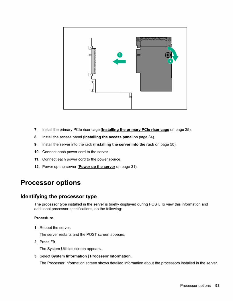
7. Install the primary PCIe riser cage (Installing the primary PCIe riser cage on page 35).
8. Install the access panel (Installing the access panel on page 34).
9. Install the server into the rack (Installing the server into the rack on page 50).
10. Connect each power cord to the server.
11. Connect each power cord to the power source.
12. Power up the server (Power up the server on page 31).
Processor options
Identifying the processor typeThe processor type installed in the server is briefly displayed during POST. To view this information andadditional processor specifications, do the following:
Procedure
1. Reboot the server.
The server restarts and the POST screen appears.
2. Press F9.
The System Utilities screen appears.
3. Select System Information | Processor Information.
The Processor Information screen shows detailed information about the processors installed in the server.
Processor options 93
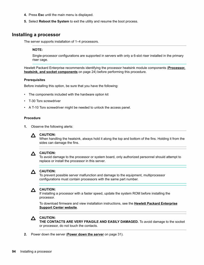
4. Press Esc until the main menu is displayed.
5. Select Reboot the System to exit the utility and resume the boot process.
Installing a processorThe server supports installation of 1–4 processors.
NOTE:
Single-processor configurations are supported in servers with only a 6-slot riser installed in the primaryriser cage.
Hewlett Packard Enterprise recommends identifying the processor heatsink module components (Processor,heatsink, and socket components on page 24) before performing this procedure.
Prerequisites
Before installing this option, be sure that you have the following:
• The components included with the hardware option kit
• T-30 Torx screwdriver
• A T-10 Torx screwdriver might be needed to unlock the access panel.
Procedure
1. Observe the following alerts:
CAUTION:When handling the heatsink, always hold it along the top and bottom of the fins. Holding it from thesides can damage the fins.
CAUTION:To avoid damage to the processor or system board, only authorized personnel should attempt toreplace or install the processor in this server.
CAUTION:To prevent possible server malfunction and damage to the equipment, multiprocessorconfigurations must contain processors with the same part number.
CAUTION:If installing a processor with a faster speed, update the system ROM before installing theprocessor.
To download firmware and view installation instructions, see the Hewlett Packard EnterpriseSupport Center website.
CAUTION:THE CONTACTS ARE VERY FRAGILE AND EASILY DAMAGED. To avoid damage to the socketor processor, do not touch the contacts.
2. Power down the server (Power down the server on page 31).
94 Installing a processor
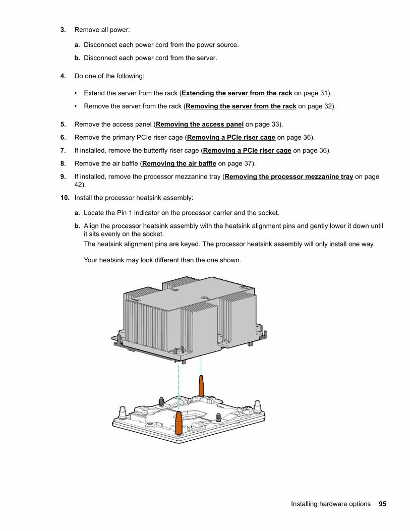
3. Remove all power:
a. Disconnect each power cord from the power source.
b. Disconnect each power cord from the server.
4. Do one of the following:
• Extend the server from the rack (Extending the server from the rack on page 31).
• Remove the server from the rack (Removing the server from the rack on page 32).
5. Remove the access panel (Removing the access panel on page 33).
6. Remove the primary PCIe riser cage (Removing a PCIe riser cage on page 36).
7. If installed, remove the butterfly riser cage (Removing a PCIe riser cage on page 36).
8. Remove the air baffle (Removing the air baffle on page 37).
9. If installed, remove the processor mezzanine tray (Removing the processor mezzanine tray on page42).
10. Install the processor heatsink assembly:
a. Locate the Pin 1 indicator on the processor carrier and the socket.
b. Align the processor heatsink assembly with the heatsink alignment pins and gently lower it down untilit sits evenly on the socket.The heatsink alignment pins are keyed. The processor heatsink assembly will only install one way.
Your heatsink may look different than the one shown.
Installing hardware options 95
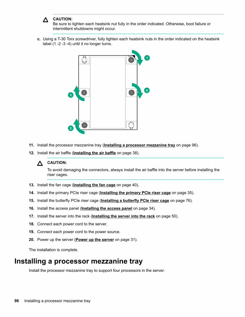
CAUTION:Be sure to tighten each heatsink nut fully in the order indicated. Otherwise, boot failure orintermittent shutdowns might occur.
c. Using a T-30 Torx screwdriver, fully tighten each heatsink nuts in the order indicated on the heatsinklabel (1 -2 -3 -4) until it no longer turns.
11. Install the processor mezzanine tray (Installing a processor mezzanine tray on page 96).
12. Install the air baffle (Installing the air baffle on page 38).
CAUTION:
To avoid damaging the connectors, always install the air baffle into the server before installing theriser cages.
13. Install the fan cage (Installing the fan cage on page 40).
14. Install the primary PCIe riser cage (Installing the primary PCIe riser cage on page 35).
15. Install the butterfly PCIe riser cage (Installing a butterfly PCIe riser cage on page 76).
16. Install the access panel (Installing the access panel on page 34).
17. Install the server into the rack (Installing the server into the rack on page 50).
18. Connect each power cord to the server.
19. Connect each power cord to the power source.
20. Power up the server (Power up the server on page 31).
The installation is complete.
Installing a processor mezzanine trayInstall the processor mezzanine tray to support four processors in the server.
96 Installing a processor mezzanine tray
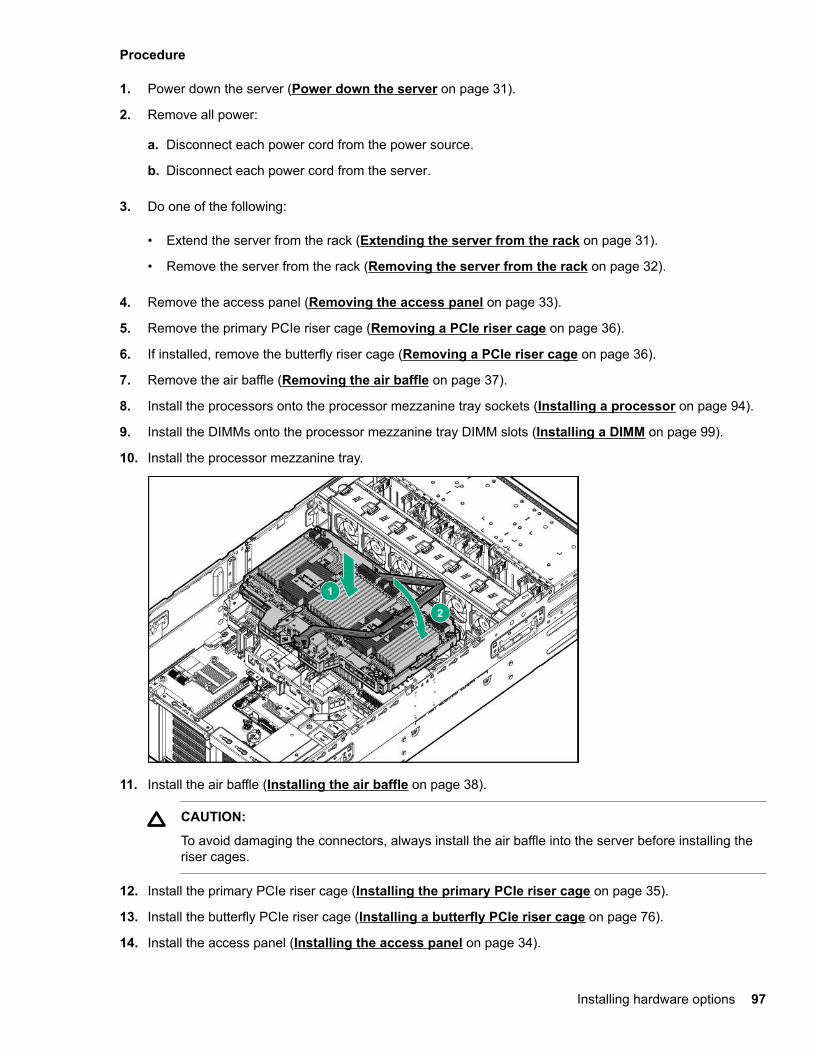
Procedure
1. Power down the server (Power down the server on page 31).
2. Remove all power:
a. Disconnect each power cord from the power source.
b. Disconnect each power cord from the server.
3. Do one of the following:
• Extend the server from the rack (Extending the server from the rack on page 31).
• Remove the server from the rack (Removing the server from the rack on page 32).
4. Remove the access panel (Removing the access panel on page 33).
5. Remove the primary PCIe riser cage (Removing a PCIe riser cage on page 36).
6. If installed, remove the butterfly riser cage (Removing a PCIe riser cage on page 36).
7. Remove the air baffle (Removing the air baffle on page 37).
8. Install the processors onto the processor mezzanine tray sockets (Installing a processor on page 94).
9. Install the DIMMs onto the processor mezzanine tray DIMM slots (Installing a DIMM on page 99).
10. Install the processor mezzanine tray.
11. Install the air baffle (Installing the air baffle on page 38).
CAUTION:
To avoid damaging the connectors, always install the air baffle into the server before installing theriser cages.
12. Install the primary PCIe riser cage (Installing the primary PCIe riser cage on page 35).
13. Install the butterfly PCIe riser cage (Installing a butterfly PCIe riser cage on page 76).
14. Install the access panel (Installing the access panel on page 34).
Installing hardware options 97
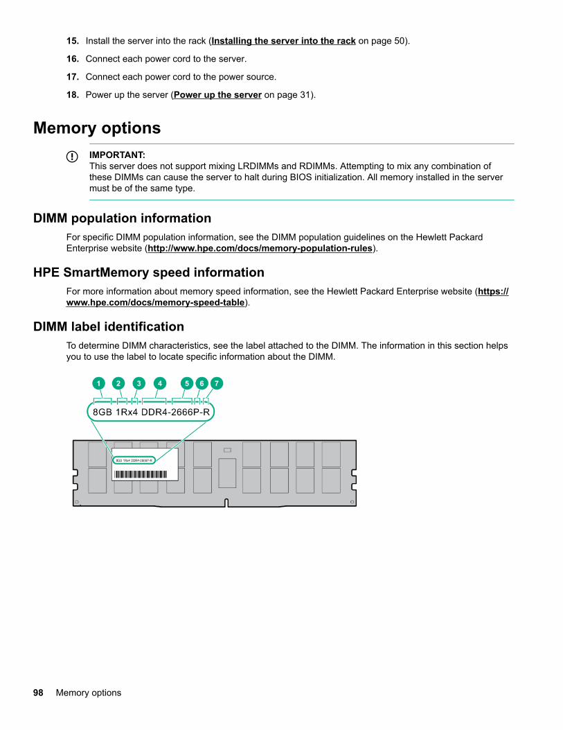
15. Install the server into the rack (Installing the server into the rack on page 50).
16. Connect each power cord to the server.
17. Connect each power cord to the power source.
18. Power up the server (Power up the server on page 31).
Memory optionsIMPORTANT:This server does not support mixing LRDIMMs and RDIMMs. Attempting to mix any combination ofthese DIMMs can cause the server to halt during BIOS initialization. All memory installed in the servermust be of the same type.
DIMM population informationFor specific DIMM population information, see the DIMM population guidelines on the Hewlett PackardEnterprise website (http://www.hpe.com/docs/memory-population-rules).
HPE SmartMemory speed informationFor more information about memory speed information, see the Hewlett Packard Enterprise website (https://www.hpe.com/docs/memory-speed-table).
DIMM label identificationTo determine DIMM characteristics, see the label attached to the DIMM. The information in this section helpsyou to use the label to locate specific information about the DIMM.
98 Memory options
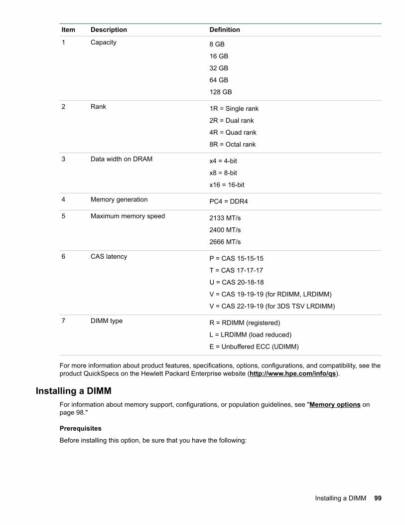
Item Description Definition
1 Capacity 8 GB
16 GB
32 GB
64 GB
128 GB
2 Rank 1R = Single rank
2R = Dual rank
4R = Quad rank
8R = Octal rank
3 Data width on DRAM x4 = 4-bit
x8 = 8-bit
x16 = 16-bit
4 Memory generation PC4 = DDR4
5 Maximum memory speed 2133 MT/s
2400 MT/s
2666 MT/s
6 CAS latency P = CAS 15-15-15
T = CAS 17-17-17
U = CAS 20-18-18
V = CAS 19-19-19 (for RDIMM, LRDIMM)
V = CAS 22-19-19 (for 3DS TSV LRDIMM)
7 DIMM type R = RDIMM (registered)
L = LRDIMM (load reduced)
E = Unbuffered ECC (UDIMM)
For more information about product features, specifications, options, configurations, and compatibility, see theproduct QuickSpecs on the Hewlett Packard Enterprise website (http://www.hpe.com/info/qs).
Installing a DIMMFor information about memory support, configurations, or population guidelines, see "Memory options onpage 98."
Prerequisites
Before installing this option, be sure that you have the following:
Installing a DIMM 99
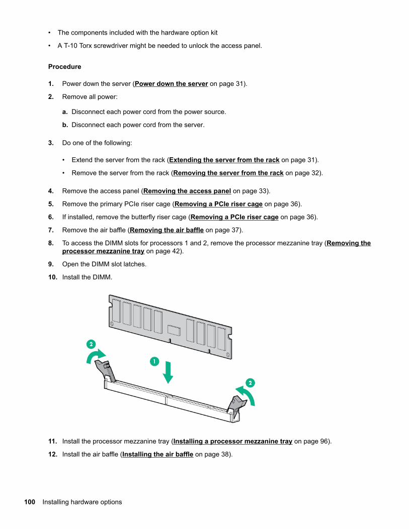
• The components included with the hardware option kit
• A T-10 Torx screwdriver might be needed to unlock the access panel.
Procedure
1. Power down the server (Power down the server on page 31).
2. Remove all power:
a. Disconnect each power cord from the power source.
b. Disconnect each power cord from the server.
3. Do one of the following:
• Extend the server from the rack (Extending the server from the rack on page 31).
• Remove the server from the rack (Removing the server from the rack on page 32).
4. Remove the access panel (Removing the access panel on page 33).
5. Remove the primary PCIe riser cage (Removing a PCIe riser cage on page 36).
6. If installed, remove the butterfly riser cage (Removing a PCIe riser cage on page 36).
7. Remove the air baffle (Removing the air baffle on page 37).
8. To access the DIMM slots for processors 1 and 2, remove the processor mezzanine tray (Removing theprocessor mezzanine tray on page 42).
9. Open the DIMM slot latches.
10. Install the DIMM.
11. Install the processor mezzanine tray (Installing a processor mezzanine tray on page 96).
12. Install the air baffle (Installing the air baffle on page 38).
100 Installing hardware options
CAUTION:
To avoid damaging the connectors, always install the air baffle into the server before installing theriser cages.
13. Install the primary PCIe riser cage (Installing the primary PCIe riser cage on page 35).
14. Install the butterfly PCIe riser cage (Installing a butterfly PCIe riser cage on page 76).
15. Install the access panel (Installing the access panel on page 34).
16. Install the server into the rack (Installing the server into the rack on page 50).
17. Connect each power cord to the server.
18. Connect each power cord to the power source.
19. Power up the server (Power up the server on page 31).
To configure the memory mode, use the BIOS/Platform Configuration (RBSU) in the System Utilities.
If a DIMM failure has occurred, see "Systems Insight Display combined LED descriptions on page 15."
Installing the 2P pass-through performance boardPrerequisites
Before installing this option, be sure that you have the following:
• T-10 Torx screwdriver
• The components included with the hardware option kit
Procedure
1. Power down the server (Power down the server on page 31).
2. Remove all power:
a. Disconnect each power cord from the power source.
b. Disconnect each power cord from the server.
3. Do one of the following:
• Extend the server from the rack (Extending the server from the rack on page 31).
• Remove the server from the rack (Removing the server from the rack on page 32).
4. Remove the access panel (Removing the access panel on page 33).
5. Remove the primary PCIe riser cage (Removing a PCIe riser cage on page 36).
6. If installed, remove the butterfly riser cage (Removing a PCIe riser cage on page 36).
7. Remove the air baffle (Removing the air baffle on page 37).
8. Remove the covers protecting the upper processor mezzanine power and signal connectors. To locatethese connectors, see "System board components on page 23".
9. Install the pass-through board.
Installing the 2P pass-through performance board 101
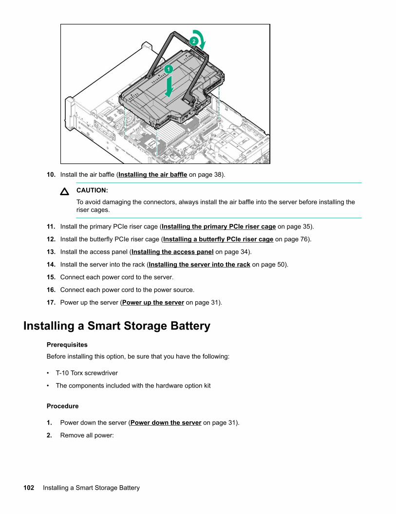
10. Install the air baffle (Installing the air baffle on page 38).
CAUTION:
To avoid damaging the connectors, always install the air baffle into the server before installing theriser cages.
11. Install the primary PCIe riser cage (Installing the primary PCIe riser cage on page 35).
12. Install the butterfly PCIe riser cage (Installing a butterfly PCIe riser cage on page 76).
13. Install the access panel (Installing the access panel on page 34).
14. Install the server into the rack (Installing the server into the rack on page 50).
15. Connect each power cord to the server.
16. Connect each power cord to the power source.
17. Power up the server (Power up the server on page 31).
Installing a Smart Storage BatteryPrerequisites
Before installing this option, be sure that you have the following:
• T-10 Torx screwdriver
• The components included with the hardware option kit
Procedure
1. Power down the server (Power down the server on page 31).
2. Remove all power:
102 Installing a Smart Storage Battery
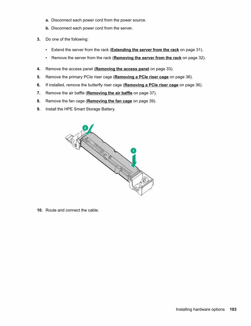
a. Disconnect each power cord from the power source.
b. Disconnect each power cord from the server.
3. Do one of the following:
• Extend the server from the rack (Extending the server from the rack on page 31).
• Remove the server from the rack (Removing the server from the rack on page 32).
4. Remove the access panel (Removing the access panel on page 33).
5. Remove the primary PCIe riser cage (Removing a PCIe riser cage on page 36).
6. If installed, remove the butterfly riser cage (Removing a PCIe riser cage on page 36).
7. Remove the air baffle (Removing the air baffle on page 37).
8. Remove the fan cage (Removing the fan cage on page 39).
9. Install the HPE Smart Storage Battery.
10. Route and connect the cable.
Installing hardware options 103
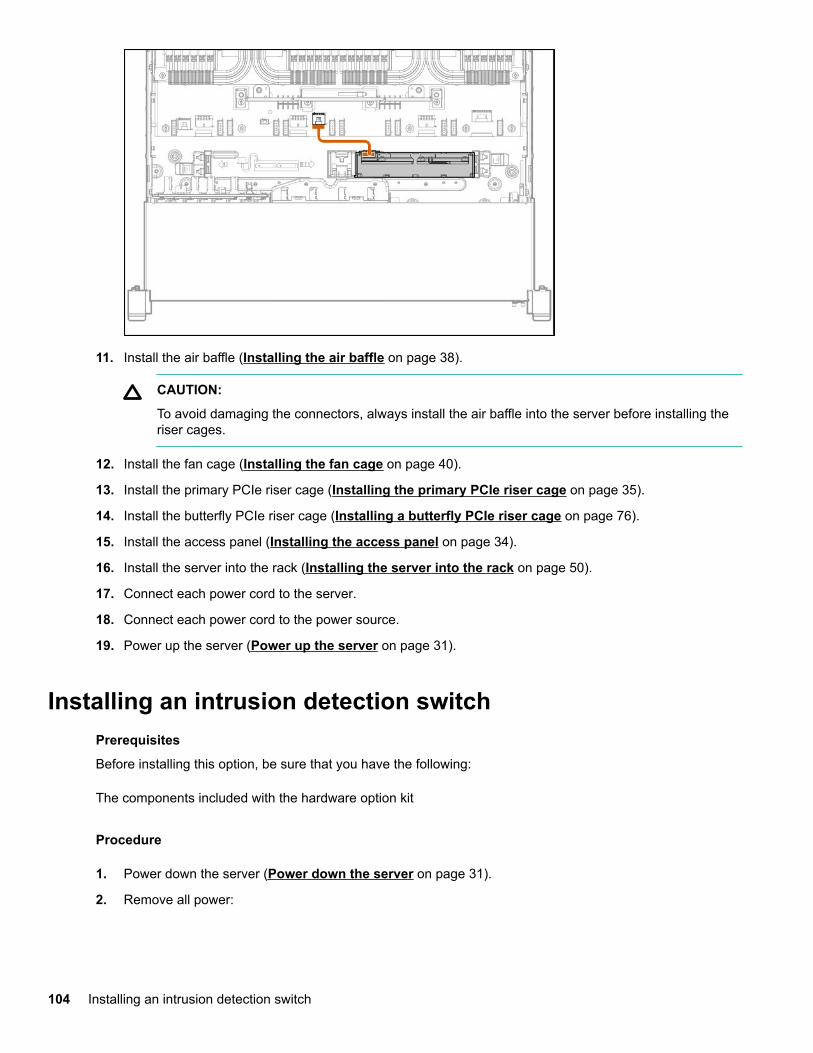
11. Install the air baffle (Installing the air baffle on page 38).
CAUTION:
To avoid damaging the connectors, always install the air baffle into the server before installing theriser cages.
12. Install the fan cage (Installing the fan cage on page 40).
13. Install the primary PCIe riser cage (Installing the primary PCIe riser cage on page 35).
14. Install the butterfly PCIe riser cage (Installing a butterfly PCIe riser cage on page 76).
15. Install the access panel (Installing the access panel on page 34).
16. Install the server into the rack (Installing the server into the rack on page 50).
17. Connect each power cord to the server.
18. Connect each power cord to the power source.
19. Power up the server (Power up the server on page 31).
Installing an intrusion detection switchPrerequisites
Before installing this option, be sure that you have the following:
The components included with the hardware option kit
Procedure
1. Power down the server (Power down the server on page 31).
2. Remove all power:
104 Installing an intrusion detection switch
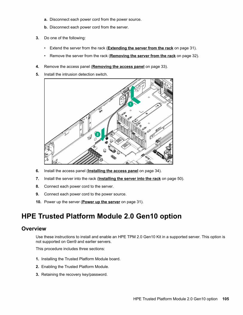
a. Disconnect each power cord from the power source.
b. Disconnect each power cord from the server.
3. Do one of the following:
• Extend the server from the rack (Extending the server from the rack on page 31).
• Remove the server from the rack (Removing the server from the rack on page 32).
4. Remove the access panel (Removing the access panel on page 33).
5. Install the intrusion detection switch.
6. Install the access panel (Installing the access panel on page 34).
7. Install the server into the rack (Installing the server into the rack on page 50).
8. Connect each power cord to the server.
9. Connect each power cord to the power source.
10. Power up the server (Power up the server on page 31).
HPE Trusted Platform Module 2.0 Gen10 optionOverview
Use these instructions to install and enable an HPE TPM 2.0 Gen10 Kit in a supported server. This option isnot supported on Gen9 and earlier servers.
This procedure includes three sections:
1. Installing the Trusted Platform Module board.
2. Enabling the Trusted Platform Module.
3. Retaining the recovery key/password.
HPE Trusted Platform Module 2.0 Gen10 option 105
HPE TPM 2.0 installation is supported with specific operating system support such as Microsoft® WindowsServer® 2012 R2 and later. For more information about operating system support, see the productQuickSpecs on the Hewlett Packard Enterprise website (http://www.hpe.com/info/qs). For more informationabout Microsoft® Windows® BitLocker Drive Encryption feature, see the Microsoft website (http://www.microsoft.com).
CAUTION:If the TPM is removed from the original server and powered up on a different server, data stored in theTPM including keys will be erased.
IMPORTANT:In UEFI Boot Mode, the HPE TPM 2.0 Gen10 Kit can be configured to operate as TPM 2.0 (default) orTPM 1.2 on a supported server. In Legacy Boot Mode, the configuration can be changed between TPM1.2 and TPM 2.0, but only TPM 1.2 operation is supported.
HPE Trusted Platform Module 2.0 Guidelines
CAUTION:Always observe the guidelines in this document. Failure to follow these guidelines can cause hardwaredamage or halt data access.
When installing or replacing a TPM, observe the following guidelines:
• Do not remove an installed TPM. Once installed, the TPM is bound to the system board. If an OS isconfigured to use the TPM and it is removed, the OS may go into recovery mode, data loss can occur, orboth.
• When installing or replacing hardware, Hewlett Packard Enterprise service providers cannot enable theTPM or the encryption technology. For security reasons, only the customer can enable these features.
• When returning a system board for service replacement, do not remove the TPM from the system board.When requested, Hewlett Packard Enterprise Service provides a TPM with the spare system board.
• Any attempt to remove the cover of an installed TPM from the system board can damage the TPM cover,the TPM, and the system board.
• If the TPM is removed from the original server and powered up on a different server, data stored in theTPM including keys will be erased.
• When using BitLocker, always retain the recovery key/password. The recovery key/password is required tocomplete Recovery Mode after BitLocker detects a possible compromise of system integrity or systemconfiguration.
• Hewlett Packard Enterprise is not liable for blocked data access caused by improper TPM use. Foroperating instructions, see the TPM documentation or the encryption technology feature documentationprovided by the operating system.
Installing and enabling the HPE TPM 2.0 Gen10 Kit
Installing the Trusted Platform Module board
106 HPE Trusted Platform Module 2.0 Guidelines
Preparing the server for installation
Procedure
1. Observe the following warnings:
WARNING:To reduce the risk of personal injury, electric shock, or damage to the equipment, remove power fromthe server by removing the power cord. The front panel Power On/Standby button does not shut offsystem power. Portions of the power supply and some internal circuitry remain active until AC poweris removed.
WARNING:To reduce the risk of personal injury from hot surfaces, allow the drives and the internal systemcomponents to cool before touching them.
2. Update the system ROM.
Locate and download the latest ROM version from the Hewlett Packard Enterprise Support Centerwebsite. Follow the instructions on the website to update the system ROM.
3. Update the system ROM.
Locate and download the latest ROM version from the Hewlett Packard Enterprise Support Center website(http://www.hpe.com/support/hpesc). To update the system ROM, follow the instructions on the website.
4. Power down the server.
a. Shut down the OS as directed by the OS documentation.
b. To place the server in standby mode, press the Power On/Standby button. When the server entersstandby power mode, the system power LED changes to amber.
c. Disconnect the power cords (rack and tower servers).
5. Do one of the following:
• Remove the server from the rack, if necessary.
• Remove the server or server blade from the server.
6. Place the server on a flat, level work surface.
7. Remove the access panel.
8. Remove any options or cables that may prevent access to the TPM connector.
9. Proceed to Installing the TPM board and cover on page 107.
Installing the TPM board and cover
Procedure
1. Observe the following alerts:
Installing hardware options 107
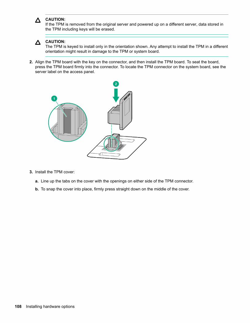
CAUTION:If the TPM is removed from the original server and powered up on a different server, data stored inthe TPM including keys will be erased.
CAUTION:The TPM is keyed to install only in the orientation shown. Any attempt to install the TPM in a differentorientation might result in damage to the TPM or system board.
2. Align the TPM board with the key on the connector, and then install the TPM board. To seat the board,press the TPM board firmly into the connector. To locate the TPM connector on the system board, see theserver label on the access panel.
3. Install the TPM cover:
a. Line up the tabs on the cover with the openings on either side of the TPM connector.
b. To snap the cover into place, firmly press straight down on the middle of the cover.
108 Installing hardware options
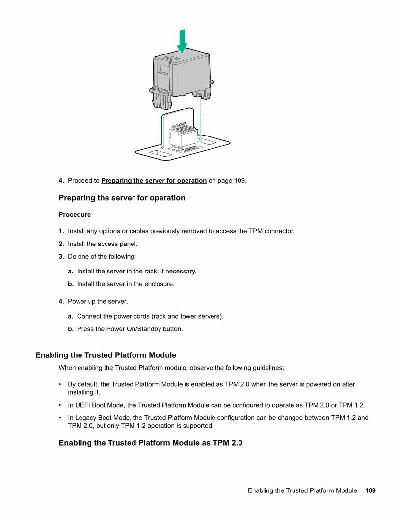
4. Proceed to Preparing the server for operation on page 109.
Preparing the server for operation
Procedure
1. Install any options or cables previously removed to access the TPM connector.
2. Install the access panel.
3. Do one of the following:
a. Install the server in the rack, if necessary.
b. Install the server in the enclosure.
4. Power up the server.
a. Connect the power cords (rack and tower servers).
b. Press the Power On/Standby button.
Enabling the Trusted Platform ModuleWhen enabling the Trusted Platform module, observe the following guidelines:
• By default, the Trusted Platform Module is enabled as TPM 2.0 when the server is powered on afterinstalling it.
• In UEFI Boot Mode, the Trusted Platform Module can be configured to operate as TPM 2.0 or TPM 1.2.
• In Legacy Boot Mode, the Trusted Platform Module configuration can be changed between TPM 1.2 andTPM 2.0, but only TPM 1.2 operation is supported.
Enabling the Trusted Platform Module as TPM 2.0
Enabling the Trusted Platform Module 109
Procedure
1. During the server startup sequence, press the F9 key to access System Utilities.
2. From the System Utilities screen, select System Configuration > BIOS/Platform Configuration (RBSU)> Server Security > Trusted Platform Module options.
3. Verify the following:
• "Current TPM Type" is set to TPM 2.0.
• "Current TPM State" is set to Present and Enabled.
• "TPM Visibility" is set to Visible.
4. If changes were made in the previous step, press the F10 key to save your selection.
5. If F10 was pressed in the previous step, do one of the following:
• If in graphical mode, click Yes.
• If in text mode, press the Y key.
6. Press the ESC key to exit System Utilities.
7. If changes were made and saved, the server prompts for reboot request. Press the Enter key to confirmreboot.
If the following actions were performed, the server reboots a second time without user input. During thisreboot, the TPM setting becomes effective.
• Changing from TPM 1.2 and TPM 2.0
• Changing TPM bus from FIFO to CRB
• Enabling or disabling TPM
• Clearing the TPM
8. Enable TPM functionality in the OS, such as Microsoft Windows BitLocker or measured boot.
For more information, see the Microsoft website.
Enabling the Trusted Platform Module as TPM 1.2
Procedure
1. During the server startup sequence, press the F9 key to access System Utilities.
2. From the System Utilities screen select System Configuration > BIOS/Platform Configuration (RBSU)> Server Security > Trusted Platform Module options.
3. Change the "TPM Mode Switch Operation" to TPM 1.2.
4. Verify "TPM Visibility" is Visible.
5. Press the F10 key to save your selection.
6. When prompted to save the change in System Utilities, do one of the following:
110 Installing hardware options
• If in graphical mode, click Yes.
• If in text mode, press the Y key.
7. Press the ESC key to exit System Utilities.
The server reboots a second time without user input. During this reboot, the TPM setting becomeseffective.
8. Enable TPM functionality in the OS, such as Microsoft Windows BitLocker or measured boot.
For more information, see the Microsoft website.
Retaining the recovery key/passwordThe recovery key/password is generated during BitLocker setup, and can be saved and printed afterBitLocker is enabled. When using BitLocker, always retain the recovery key/password. The recovery key/password is required to enter Recovery Mode after BitLocker detects a possible compromise of systemintegrity.
To help ensure maximum security, observe the following guidelines when retaining the recovery key/password:
• Always store the recovery key/password in multiple locations.
• Always store copies of the recovery key/password away from the server.
• Do not save the recovery key/password on the encrypted hard drive.
Retaining the recovery key/password 111

Cabling
HPE ProLiant Gen10 DL Servers Storage Cabling GuidelinesWhen installing cables, observe the following:
• All ports are labeled:
◦ System board ports
◦ Controller ports
◦ 12G SAS Expander ports
• Most data cables have labels near each connector with destination port information.
• Some data cables are pre-bent. Do not unbend or manipulate the cables.
• Before connecting a cable to a port, lay the cable in place to verify the length of the cable.
• When routing cables from the front to the rear of the server, use the cable channels on either side of thechassis.
Cable matrixUse the following tables to find cabling information and part numbers.
SAS/SATA kits
Option kit Cable partnumber*
From To Power cable partnumber
2SFF SAS/SATA drive cage 869952-001 1 Drivebackplane
System board 870479-001 2
8SFF SAS/SATA drive cage 870480-001 3 Drivebackplane(drive boxes 1,3, 4, and 6)
Primary risercage
Tertiary risercage
870479-001 2
8SFF SAS/SATA drive cage 870483-001 3 Drivebackplane(drive boxes1–6)
Primary risercage
Tertiary risercage
870479-001 2
8SFF SAS/SATA drive cage (miniSAS)
870492-001 4 Drivebackplane(drive boxes 1,3, 4, and 6)
Primary risercage
Tertiary risercage
870479-001 2
Table Continued
112 Cabling
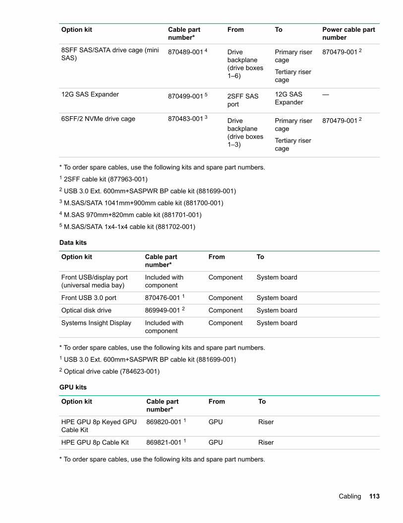
Option kit Cable partnumber*
From To Power cable partnumber
8SFF SAS/SATA drive cage (miniSAS)
870489-001 4 Drivebackplane(drive boxes1–6)
Primary risercage
Tertiary risercage
870479-001 2
12G SAS Expander 870499-001 5 2SFF SASport
12G SASExpander
—
6SFF/2 NVMe drive cage 870483-001 3 Drivebackplane(drive boxes1–3)
Primary risercage
Tertiary risercage
870479-001 2
* To order spare cables, use the following kits and spare part numbers.1 2SFF cable kit (877963-001)2 USB 3.0 Ext. 600mm+SASPWR BP cable kit (881699-001)3 M.SAS/SATA 1041mm+900mm cable kit (881700-001)4 M.SAS 970mm+820mm cable kit (881701-001)5 M.SAS/SATA 1x4-1x4 cable kit (881702-001)
Data kits
Option kit Cable partnumber*
From To
Front USB/display port(universal media bay)
Included withcomponent
Component System board
Front USB 3.0 port 870476-001 1 Component System board
Optical disk drive 869949-001 2 Component System board
Systems Insight Display Included withcomponent
Component System board
* To order spare cables, use the following kits and spare part numbers.1 USB 3.0 Ext. 600mm+SASPWR BP cable kit (881699-001)2 Optical drive cable (784623-001)
GPU kits
Option kit Cable partnumber*
From To
HPE GPU 8p Keyed GPUCable Kit
869820-001 1 GPU Riser
HPE GPU 8p Cable Kit 869821-001 1 GPU Riser
* To order spare cables, use the following kits and spare part numbers.
Cabling 113
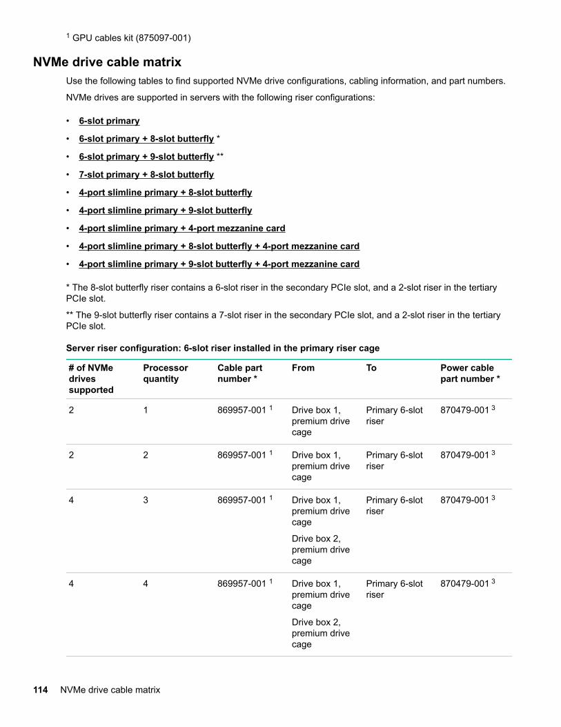
1 GPU cables kit (875097-001)
NVMe drive cable matrixUse the following tables to find supported NVMe drive configurations, cabling information, and part numbers.
NVMe drives are supported in servers with the following riser configurations:
• 6-slot primary
• 6-slot primary + 8-slot butterfly *
• 6-slot primary + 9-slot butterfly **
• 7-slot primary + 8-slot butterfly
• 4-port slimline primary + 8-slot butterfly
• 4-port slimline primary + 9-slot butterfly
• 4-port slimline primary + 4-port mezzanine card
• 4-port slimline primary + 8-slot butterfly + 4-port mezzanine card
• 4-port slimline primary + 9-slot butterfly + 4-port mezzanine card
* The 8-slot butterfly riser contains a 6-slot riser in the secondary PCIe slot, and a 2-slot riser in the tertiaryPCIe slot.
** The 9-slot butterfly riser contains a 7-slot riser in the secondary PCIe slot, and a 2-slot riser in the tertiaryPCIe slot.
Server riser configuration: 6-slot riser installed in the primary riser cage
# of NVMedrivessupported
Processorquantity
Cable partnumber *
From To Power cablepart number *
2 1 869957-001 1 Drive box 1,premium drivecage
Primary 6-slotriser
870479-001 3
2 2 869957-001 1 Drive box 1,premium drivecage
Primary 6-slotriser
870479-001 3
4 3 869957-001 1 Drive box 1,premium drivecage
Drive box 2,premium drivecage
Primary 6-slotriser
870479-001 3
4 4 869957-001 1 Drive box 1,premium drivecage
Drive box 2,premium drivecage
Primary 6-slotriser
870479-001 3
114 NVMe drive cable matrix
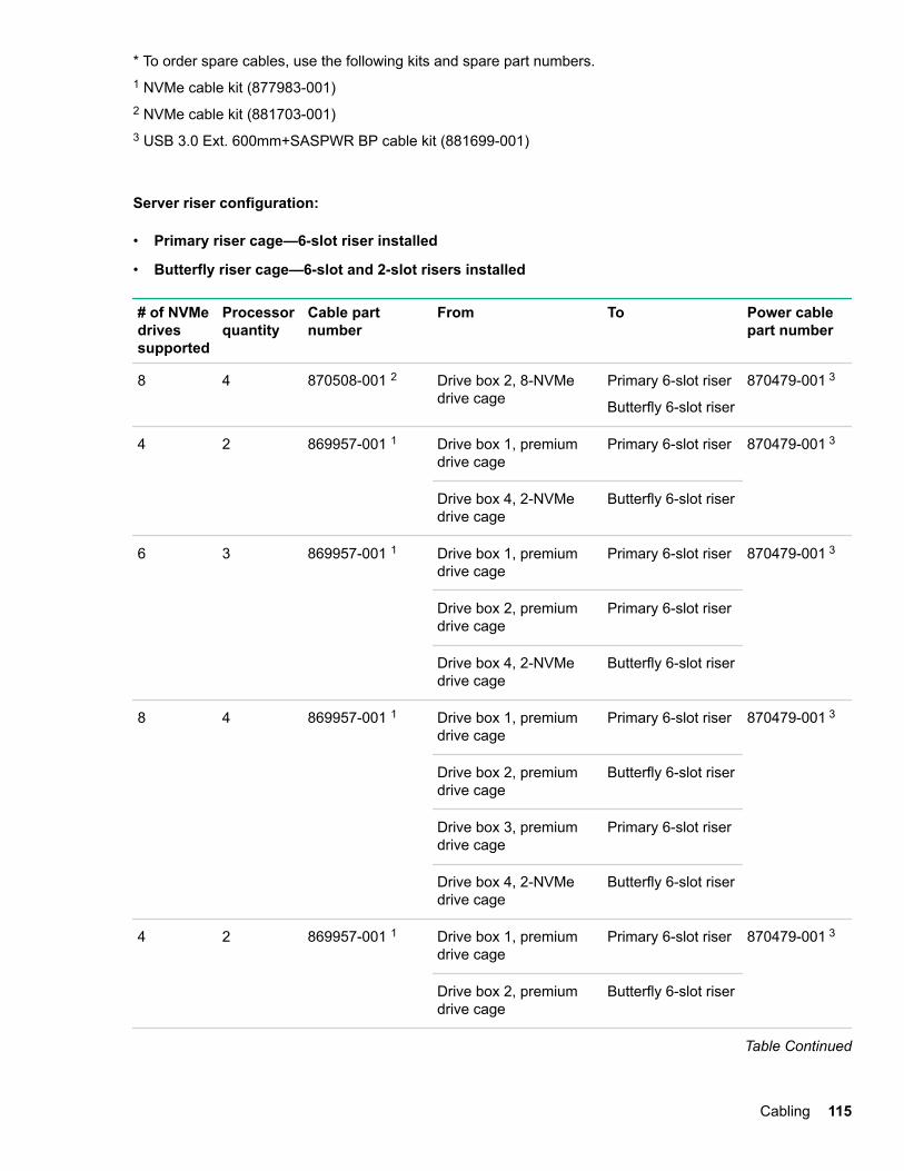
* To order spare cables, use the following kits and spare part numbers.1 NVMe cable kit (877983-001)2 NVMe cable kit (881703-001)3 USB 3.0 Ext. 600mm+SASPWR BP cable kit (881699-001)
Server riser configuration:
• Primary riser cage—6-slot riser installed
• Butterfly riser cage—6-slot and 2-slot risers installed
# of NVMedrivessupported
Processorquantity
Cable partnumber
From To Power cablepart number
8 4 870508-001 2 Drive box 2, 8-NVMedrive cage
Primary 6-slot riser
Butterfly 6-slot riser
870479-001 3
4 2 869957-001 1 Drive box 1, premiumdrive cage
Primary 6-slot riser 870479-001 3
Drive box 4, 2-NVMedrive cage
Butterfly 6-slot riser
6 3 869957-001 1 Drive box 1, premiumdrive cage
Primary 6-slot riser 870479-001 3
Drive box 2, premiumdrive cage
Primary 6-slot riser
Drive box 4, 2-NVMedrive cage
Butterfly 6-slot riser
8 4 869957-001 1 Drive box 1, premiumdrive cage
Primary 6-slot riser 870479-001 3
Drive box 2, premiumdrive cage
Butterfly 6-slot riser
Drive box 3, premiumdrive cage
Primary 6-slot riser
Drive box 4, 2-NVMedrive cage
Butterfly 6-slot riser
4 2 869957-001 1 Drive box 1, premiumdrive cage
Primary 6-slot riser 870479-001 3
Drive box 2, premiumdrive cage
Butterfly 6-slot riser
Table Continued
Cabling 115
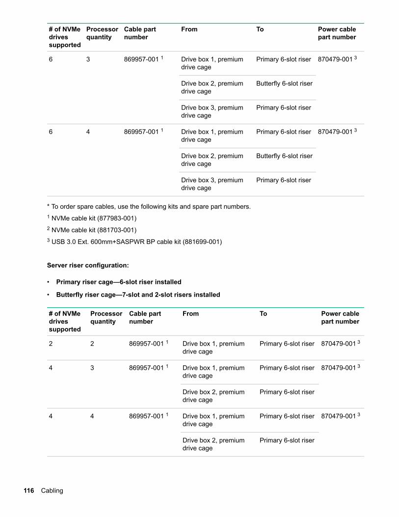
# of NVMedrivessupported
Processorquantity
Cable partnumber
From To Power cablepart number
6 3 869957-001 1 Drive box 1, premiumdrive cage
Primary 6-slot riser 870479-001 3
Drive box 2, premiumdrive cage
Butterfly 6-slot riser
Drive box 3, premiumdrive cage
Primary 6-slot riser
6 4 869957-001 1 Drive box 1, premiumdrive cage
Primary 6-slot riser 870479-001 3
Drive box 2, premiumdrive cage
Butterfly 6-slot riser
Drive box 3, premiumdrive cage
Primary 6-slot riser
* To order spare cables, use the following kits and spare part numbers.1 NVMe cable kit (877983-001)2 NVMe cable kit (881703-001)3 USB 3.0 Ext. 600mm+SASPWR BP cable kit (881699-001)
Server riser configuration:
• Primary riser cage—6-slot riser installed
• Butterfly riser cage—7-slot and 2-slot risers installed
# of NVMedrivessupported
Processorquantity
Cable partnumber
From To Power cablepart number
2 2 869957-001 1 Drive box 1, premiumdrive cage
Primary 6-slot riser 870479-001 3
4 3 869957-001 1 Drive box 1, premiumdrive cage
Primary 6-slot riser 870479-001 3
Drive box 2, premiumdrive cage
Primary 6-slot riser
4 4 869957-001 1 Drive box 1, premiumdrive cage
Primary 6-slot riser 870479-001 3
Drive box 2, premiumdrive cage
Primary 6-slot riser
116 Cabling
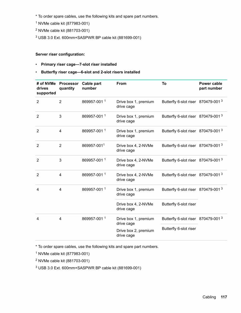
* To order spare cables, use the following kits and spare part numbers.1 NVMe cable kit (877983-001)2 NVMe cable kit (881703-001)3 USB 3.0 Ext. 600mm+SASPWR BP cable kit (881699-001)
Server riser configuration:
• Primary riser cage—7-slot riser installed
• Butterfly riser cage—6-slot and 2-slot risers installed
# of NVMedrivessupported
Processorquantity
Cable partnumber
From To Power cablepart number
2 2 869957-001 1 Drive box 1, premiumdrive cage
Butterfly 6-slot riser 870479-001 3
2 3 869957-001 1 Drive box 1, premiumdrive cage
Butterfly 6-slot riser 870479-001 3
2 4 869957-001 1 Drive box 1, premiumdrive cage
Butterfly 6-slot riser 870479-001 3
2 2 869957-0011 Drive box 4, 2-NVMedrive cage
Butterfly 6-slot riser 870479-001 3
2 3 869957-001 1 Drive box 4, 2-NVMedrive cage
Butterfly 6-slot riser 870479-001 3
2 4 869957-001 1 Drive box 4, 2-NVMedrive cage
Butterfly 6-slot riser 870479-001 3
4 4 869957-001 1 Drive box 1, premiumdrive cage
Butterfly 6-slot riser 870479-001 3
Drive box 4, 2-NVMedrive cage
Butterfly 6-slot riser
4 4 869957-001 1 Drive box 1, premiumdrive cage
Drive box 2, premiumdrive cage
Butterfly 6-slot riser 870479-001 3
Butterfly 6-slot riser
* To order spare cables, use the following kits and spare part numbers.1 NVMe cable kit (877983-001)2 NVMe cable kit (881703-001)3 USB 3.0 Ext. 600mm+SASPWR BP cable kit (881699-001)
Cabling 117
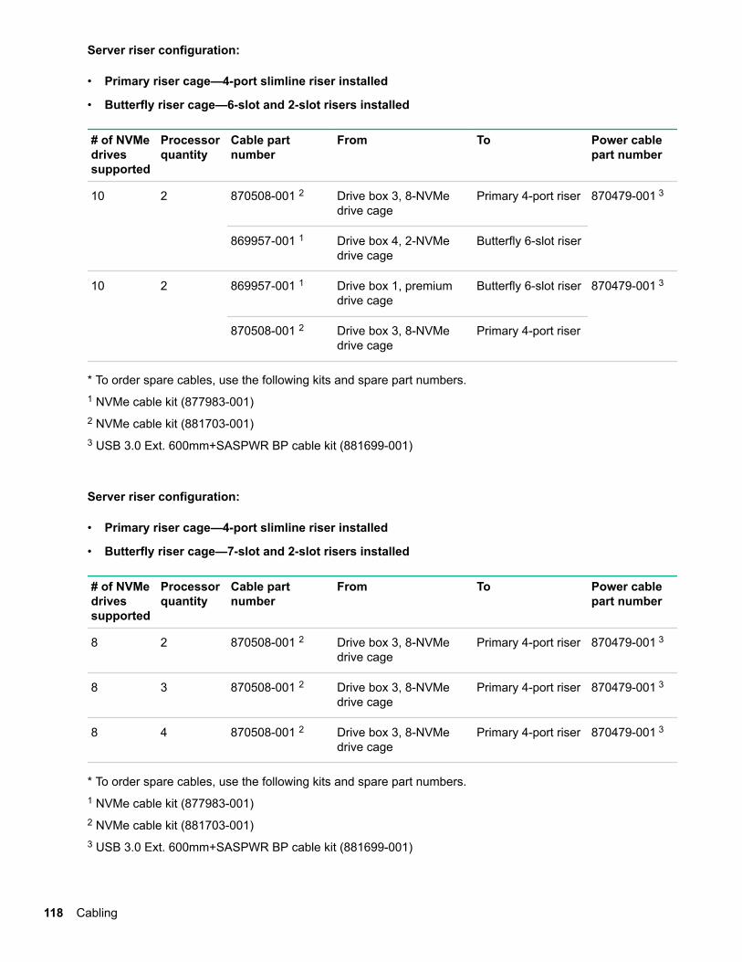
Server riser configuration:
• Primary riser cage—4-port slimline riser installed
• Butterfly riser cage—6-slot and 2-slot risers installed
# of NVMedrivessupported
Processorquantity
Cable partnumber
From To Power cablepart number
10 2 870508-001 2 Drive box 3, 8-NVMedrive cage
Primary 4-port riser 870479-001 3
869957-001 1 Drive box 4, 2-NVMedrive cage
Butterfly 6-slot riser
10 2 869957-001 1 Drive box 1, premiumdrive cage
Butterfly 6-slot riser 870479-001 3
870508-001 2 Drive box 3, 8-NVMedrive cage
Primary 4-port riser
* To order spare cables, use the following kits and spare part numbers.1 NVMe cable kit (877983-001)2 NVMe cable kit (881703-001)3 USB 3.0 Ext. 600mm+SASPWR BP cable kit (881699-001)
Server riser configuration:
• Primary riser cage—4-port slimline riser installed
• Butterfly riser cage—7-slot and 2-slot risers installed
# of NVMedrivessupported
Processorquantity
Cable partnumber
From To Power cablepart number
8 2 870508-001 2 Drive box 3, 8-NVMedrive cage
Primary 4-port riser 870479-001 3
8 3 870508-001 2 Drive box 3, 8-NVMedrive cage
Primary 4-port riser 870479-001 3
8 4 870508-001 2 Drive box 3, 8-NVMedrive cage
Primary 4-port riser 870479-001 3
* To order spare cables, use the following kits and spare part numbers.1 NVMe cable kit (877983-001)2 NVMe cable kit (881703-001)3 USB 3.0 Ext. 600mm+SASPWR BP cable kit (881699-001)
118 Cabling
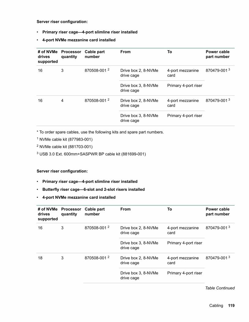
Server riser configuration:
• Primary riser cage—4-port slimline riser installed
• 4-port NVMe mezzanine card installed
# of NVMedrivessupported
Processorquantity
Cable partnumber
From To Power cablepart number
16 3 870508-001 2 Drive box 2, 8-NVMedrive cage
4-port mezzaninecard
870479-001 3
Drive box 3, 8-NVMedrive cage
Primary 4-port riser
16 4 870508-001 2 Drive box 2, 8-NVMedrive cage
4-port mezzaninecard
870479-001 3
Drive box 3, 8-NVMedrive cage
Primary 4-port riser
* To order spare cables, use the following kits and spare part numbers.1 NVMe cable kit (877983-001)2 NVMe cable kit (881703-001)3 USB 3.0 Ext. 600mm+SASPWR BP cable kit (881699-001)
Server riser configuration:
• Primary riser cage—4-port slimline riser installed
• Butterfly riser cage—6-slot and 2-slot risers installed
• 4-port NVMe mezzanine card installed
# of NVMedrivessupported
Processorquantity
Cable partnumber
From To Power cablepart number
16 3 870508-001 2 Drive box 2, 8-NVMedrive cage
4-port mezzaninecard
870479-001 3
Drive box 3, 8-NVMedrive cage
Primary 4-port riser
18 3 870508-001 2 Drive box 2, 8-NVMedrive cage
4-port mezzaninecard
870479-001 3
Drive box 3, 8-NVMedrive cage
Primary 4-port riser
Table Continued
Cabling 119
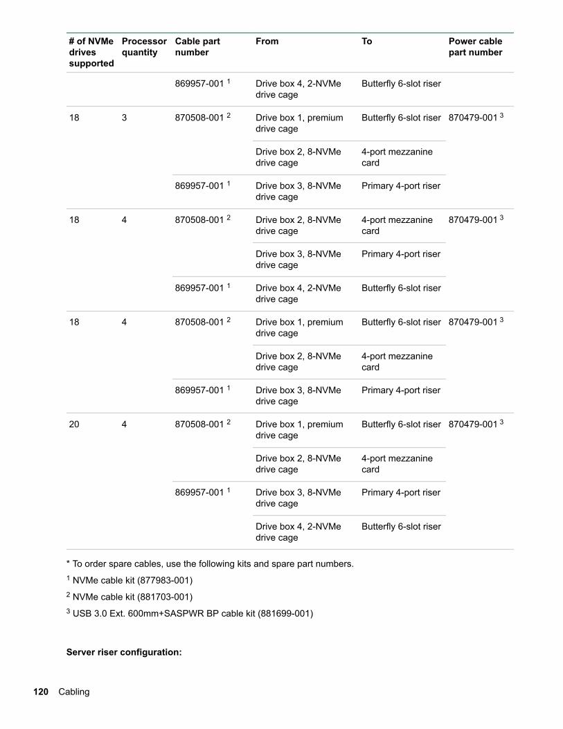
# of NVMedrivessupported
Processorquantity
Cable partnumber
From To Power cablepart number
869957-001 1 Drive box 4, 2-NVMedrive cage
Butterfly 6-slot riser
18 3 870508-001 2 Drive box 1, premiumdrive cage
Butterfly 6-slot riser 870479-001 3
Drive box 2, 8-NVMedrive cage
4-port mezzaninecard
869957-001 1 Drive box 3, 8-NVMedrive cage
Primary 4-port riser
18 4 870508-001 2 Drive box 2, 8-NVMedrive cage
4-port mezzaninecard
870479-001 3
Drive box 3, 8-NVMedrive cage
Primary 4-port riser
869957-001 1 Drive box 4, 2-NVMedrive cage
Butterfly 6-slot riser
18 4 870508-001 2 Drive box 1, premiumdrive cage
Butterfly 6-slot riser 870479-001 3
Drive box 2, 8-NVMedrive cage
4-port mezzaninecard
869957-001 1 Drive box 3, 8-NVMedrive cage
Primary 4-port riser
20 4 870508-001 2 Drive box 1, premiumdrive cage
Butterfly 6-slot riser 870479-001 3
Drive box 2, 8-NVMedrive cage
4-port mezzaninecard
869957-001 1 Drive box 3, 8-NVMedrive cage
Primary 4-port riser
Drive box 4, 2-NVMedrive cage
Butterfly 6-slot riser
* To order spare cables, use the following kits and spare part numbers.1 NVMe cable kit (877983-001)2 NVMe cable kit (881703-001)3 USB 3.0 Ext. 600mm+SASPWR BP cable kit (881699-001)
Server riser configuration:
120 Cabling
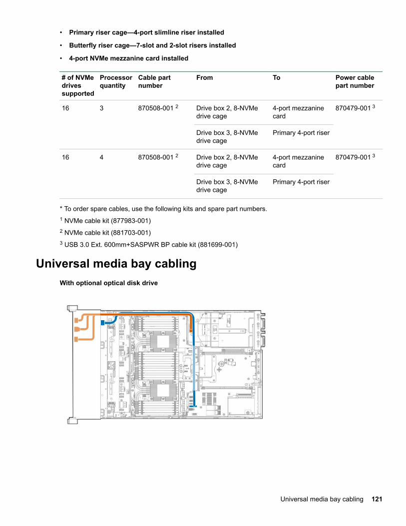
• Primary riser cage—4-port slimline riser installed
• Butterfly riser cage—7-slot and 2-slot risers installed
• 4-port NVMe mezzanine card installed
# of NVMedrivessupported
Processorquantity
Cable partnumber
From To Power cablepart number
16 3 870508-001 2 Drive box 2, 8-NVMedrive cage
4-port mezzaninecard
870479-001 3
Drive box 3, 8-NVMedrive cage
Primary 4-port riser
16 4 870508-001 2 Drive box 2, 8-NVMedrive cage
4-port mezzaninecard
870479-001 3
Drive box 3, 8-NVMedrive cage
Primary 4-port riser
* To order spare cables, use the following kits and spare part numbers.1 NVMe cable kit (877983-001)2 NVMe cable kit (881703-001)3 USB 3.0 Ext. 600mm+SASPWR BP cable kit (881699-001)
Universal media bay cablingWith optional optical disk drive
Universal media bay cabling 121
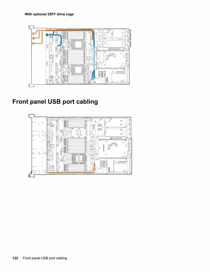
With optional 2SFF drive cage
Front panel USB port cabling
122 Front panel USB port cabling
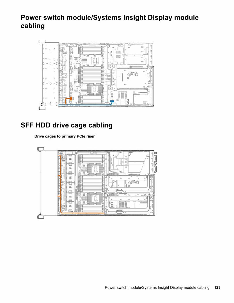
Power switch module/Systems Insight Display modulecabling
SFF HDD drive cage cablingDrive cages to primary PCIe riser
Power switch module/Systems Insight Display module cabling 123
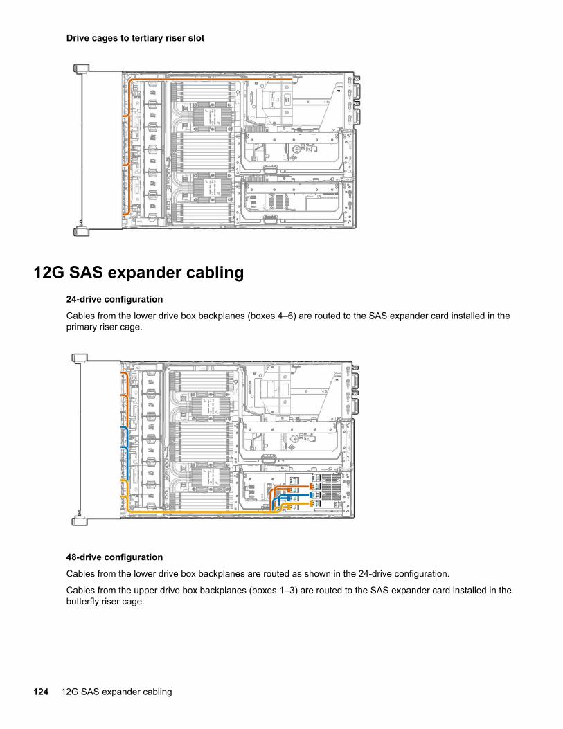
Drive cages to tertiary riser slot
12G SAS expander cabling24-drive configuration
Cables from the lower drive box backplanes (boxes 4–6) are routed to the SAS expander card installed in theprimary riser cage.
48-drive configuration
Cables from the lower drive box backplanes are routed as shown in the 24-drive configuration.
Cables from the upper drive box backplanes (boxes 1–3) are routed to the SAS expander card installed in thebutterfly riser cage.
124 12G SAS expander cabling
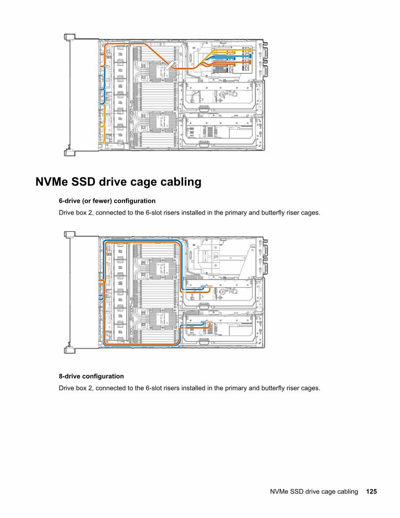
NVMe SSD drive cage cabling6-drive (or fewer) configuration
Drive box 2, connected to the 6-slot risers installed in the primary and butterfly riser cages.
8-drive configuration
Drive box 2, connected to the 6-slot risers installed in the primary and butterfly riser cages.
NVMe SSD drive cage cabling 125
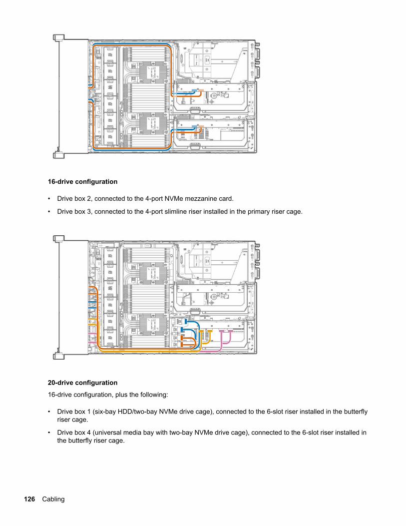
16-drive configuration
• Drive box 2, connected to the 4-port NVMe mezzanine card.
• Drive box 3, connected to the 4-port slimline riser installed in the primary riser cage.
20-drive configuration
16-drive configuration, plus the following:
• Drive box 1 (six-bay HDD/two-bay NVMe drive cage), connected to the 6-slot riser installed in the butterflyriser cage.
• Drive box 4 (universal media bay with two-bay NVMe drive cage), connected to the 6-slot riser installed inthe butterfly riser cage.
126 Cabling
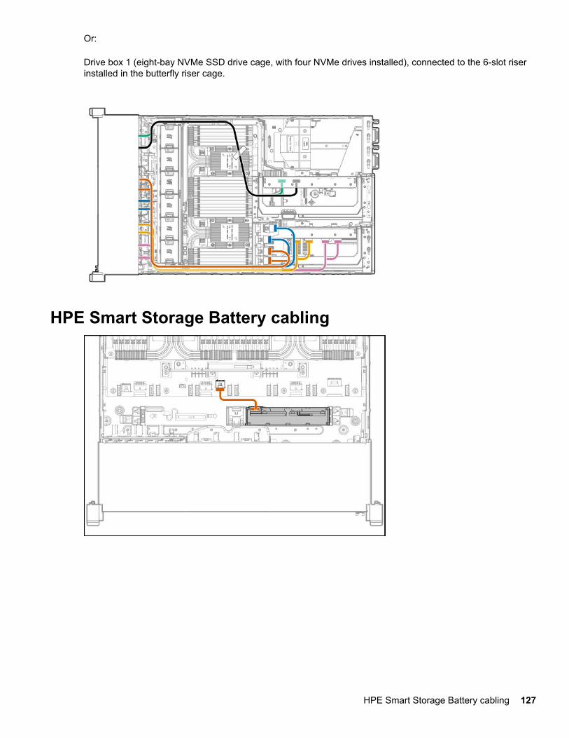
Or:
Drive box 1 (eight-bay NVMe SSD drive cage, with four NVMe drives installed), connected to the 6-slot riserinstalled in the butterfly riser cage.
HPE Smart Storage Battery cabling
HPE Smart Storage Battery cabling 127
Software and configuration utilitiesServer mode
The software and configuration utilities presented in this section operate in online mode, offline mode, or inboth modes.
Software or configuration utility Server mode
Active Health System on page 128 Online and Offline
HPE iLO 5 on page 129 Online and Offline
HPE Smart Storage Administrator on page 135 Online and Offline
iLO RESTful API on page 131 Online and Offline
Intelligent Provisioning on page 131 Offline
Scripting Toolkit for Windows and Linux on page133
Online
Service Pack for ProLiant on page 136 Online and Offline
Smart Update Manager on page 137 Online and Offline
UEFI System Utilities on page 133 Offline
Product QuickSpecsFor more information about product features, specifications, options, configurations, and compatibility, see theproduct QuickSpecs on the Hewlett Packard Enterprise website (http://www.hpe.com/info/qs).
Active Health System ViewerActive Health System Viewer (AHSV) is an online tool used to read, diagnose, and resolve server issuesquickly using AHS uploaded data. AHSV provides Hewlett Packard Enterprise recommended repair actionsbased on experience and best practices. AHSV provides the ability to:
• Read server configuration information
• View Driver/Firmware inventory
• Review Event Logs
• Respond to Fault Detection Analytics alerts
• Open new and update existing support cases
Active Health SystemThe Active Health System monitors and records changes in the server hardware and system configuration.
The Active Health System provides:
128 Software and configuration utilities

• Continuous health monitoring of over 1600 system parameters
• Logging of all configuration changes
• Consolidated health and service alerts with precise time stamps
• Agentless monitoring that does not affect application performance
For more information about the Active Health System, see the iLO user guide on the Hewlett PackardEnterprise website.
Active Health System data collectionThe Active Health System does not collect information about your operations, finances, customers,employees, or partners.
Examples of information that is collected:
• Server model and serial number
• Processor model and speed
• Storage capacity and speed
• Memory capacity and speed
• Firmware/BIOS and driver versions and settings
The Active Health System does not parse or change OS data from third-party error event log activities (forexample, content created or passed through the OS).
Active Health System LogThe data collected by the Active Health System is stored in the Active Health System Log. The data is loggedsecurely, isolated from the operating system, and separate from customer data.
When the Active Health System Log is full, new data overwrites the oldest data in the log.
It takes less than 5 minutes to download the Active Health System Log and send it to a support professionalto help you resolve an issue.
When you download and send Active Health System data to Hewlett Packard Enterprise, you agree to havethe data used for analysis, technical resolution, and quality improvements. The data that is collected ismanaged according to the privacy statement, available at http://www.hpe.com/info/privacy.
You can also upload the log to the Active Health System Viewer. For more information, see the Active HealthSystem Viewer documentation at the following website: http://www.hpe.com/support/ahsv-docs.
HPE iLO 5iLO 5 is a remote server management processor embedded on the system boards of HPE ProLiant serversand Synergy compute modules. iLO enables the monitoring and controlling of servers from remote locations.iLO management is a powerful tool that provides multiple ways to configure, update, monitor, and repairservers remotely. iLO (Standard) comes preconfigured on Hewlett Packard Enterprise servers without anadditional cost or license.
Features that enhance server administrator productivity and additional new security features are licensed. Formore information, see the iLO licensing guide at the following website: http://www.hpe.com/support/ilo-docs.
For more information about iLO, see the iLO user guide on the Hewlett Packard Enterprise website.
Active Health System data collection 129
iLO FederationiLO Federation enables you to manage multiple servers from one system using the iLO web interface.
When configured for iLO Federation, iLO uses multicast discovery and peer-to-peer communication to enablecommunication between the systems in an iLO Federation group.
When an iLO Federation page loads, a data request is sent from the iLO system running the web interface toits peers, and from those peers to other peers until all data for the selected iLO Federation group is retrieved.
iLO supports the following features:
• Group health status—View server health and model information.
• Group Virtual Media—Connect scripted media for access by the servers in an iLO Federation group.
• Group power control—Manage the power status of the servers in an iLO Federation group.
• Group power capping—Set dynamic power caps for the servers in an iLO Federation group.
• Group firmware update—Update the firmware of the servers in an iLO Federation group.
• Group license installation—Enter a license key to activate iLO licensed features on the servers in an iLOFederation group.
• Group configuration—Add iLO Federation group memberships for multiple iLO systems.
Any user can view information on iLO Federation pages, but a license is required for using the followingfeatures: Group Virtual Media, Group power control, Group power capping, Group configuration, and Groupfirmware update.
For more information about iLO Federation, see the iLO user guide on the Hewlett Packard Enterprisewebsite.
iLO Service PortThe Service Port is a USB port with the label iLO on ProLiant Gen10 servers and Synergy Gen10 computemodules.
When you have physical access to a server, you can use the Service Port to do the following:
• Download the Active Health System Log to a supported USB flash drive.
When you use this feature, the connected USB flash drive is not accessible by the host operating system.
• Connect a client (such as a laptop) with a supported USB to Ethernet adapter to access the iLO webinterface, remote console, CLI, iLO RESTful API, or scripts.
Hewlett Packard Enterprise recommends the HPE USB to Ethernet Adapter (part number Q7Y55A).
When you use the iLO Service Port:
• Actions are logged in the iLO Event Log.
• The server UID blinks to indicate the Service Port status.
You can also retrieve the Service Port status by using a REST client and the iLO RESTful API.
• You cannot use the Service Port to boot any device within the server, or the server itself.
130 iLO Federation
• You cannot access the server by connecting to the Service Port.
• You cannot access the connected device from the server.
For more information about the iLO Service Port, see the iLO user guide on the Hewlett Packard Enterprisewebsite.
iLO RESTful APIiLO includes the iLO RESTful API, which is Redfish API conformant. The iLO RESTful API is a managementinterface that server management tools can use to perform configuration, inventory, and monitoring tasks bysending basic HTTPS operations (GET, PUT, POST, DELETE, and PATCH) to the iLO web server.
To learn more about the iLO RESTful API, see the Hewlett Packard Enterprise website (http://www.hpe.com/info/restfulinterface/docs).
For specific information about automating tasks using the iLO RESTful API, see libraries and sample code at http://www.hpe.com/info/redfish.
RESTful Interface ToolThe RESTful Interface Tool (iLOrest) is a scripting tool that allows you to automate HPE server managementtasks. It provides a set of simplified commands that take advantage of the iLO RESTful API. You can installthe tool on your computer for remote use or install it locally on a server with a Windows or Linux OperatingSystem. The RESTful Interface Tool offers an interactive mode, a scriptable mode, and a file-based modesimilar to CONREP to help decrease automation times.
For more information, see the following website: http://www.hpe.com/info/resttool.
iLO Amplifier PackThe iLO Amplifier Pack is an advanced server inventory and firmware and driver update solution that enablesrapid discovery, detailed inventory reporting, and firmware and driver updates by leveraging iLO advancedfunctionality. The iLO Amplifier Pack performs rapid server discovery and inventory for thousands ofsupported servers for the purpose of updating firmware and drivers at scale.
For more information about iLO Amplifier Pack, see the iLO Amplifier Pack User Guide at the followingwebsite: http://www.hpe.com/support/ilo-ap-ug-en.
Intelligent ProvisioningIntelligent Provisioning is a single-server deployment tool embedded in ProLiant servers and HPE Synergycompute modules. Intelligent Provisioning simplifies server setup, providing a reliable and consistent way todeploy servers.
Intelligent Provisioning prepares the system for installing original, licensed vendor media and Hewlett PackardEnterprise-branded versions of OS software. Intelligent Provisioning also prepares the system to integrateoptimized server support software from the Service Pack for ProLiant (SPP). SPP is a comprehensivesystems software and firmware solution for ProLiant servers, server blades, their enclosures, and HPESynergy compute modules. These components are preloaded with a basic set of firmware and OScomponents that are installed along with Intelligent Provisioning.
IMPORTANT:
HPE ProLiant XL servers do not support operating system installation with Intelligent Provisioning, butthey do support the maintenance features. For more information, see "Performing Maintenance" in theIntelligent Provisioning User Guide and online help.
iLO RESTful API 131
After the server is running, you can update the firmware to install additional components. You can also updateany components that have been outdated since the server was manufactured.
To access Intelligent Provisioning:
• Press F10 from the POST screen.
• From the iLO web browser user interface using Always On. Always On allows you to access IntelligentProvisioning without rebooting your server.
Intelligent Provisioning operationIntelligent Provisioning includes the following components:
• Critical boot drivers
• Active Health System (AHS)
• Erase Utility
• Deployment Settings
IMPORTANT:
• Although your server is pre-loaded with firmware and drivers, you should update the firmware uponinitial setup to ensure you have the latest versions. Also, downloading and updating the latestversion of Intelligent Provisioning ensures the latest supported features are available.
• For ProLiant servers, firmware is updated using the Intelligent Provisioning Firmware Update utility.
• Do not update firmware if the version you are currently running is required for compatibility.
NOTE:
Intelligent Provisioning does not function within multihomed configurations. A multihomed host is onethat is connected to two or more networks or has two or more IP addresses.
Intelligent Provisioning provides installation help for the following operating systems:
• Microsoft Windows Server
• Red Hat Enterprise Linux
• SUSE Linux Enterprise Server
• VMware ESXi/vSphere Custom Image
Not all versions of an OS are supported. For information about specific versions of a supported operatingsystem, see the OS Support Matrix on the Hewlett Packard Enterprise website (http://www.hpe.com/info/ossupport).
Management SecurityHPE ProLiant Gen10 servers are built with some of the industry's most advanced security capabilities, out ofthe box, with a foundation of secure embedded management applications and firmware. The managementsecurity provided by HPE embedded management products enables secure support of modern workloads,protecting your components from unauthorized access and unapproved use. The range of embeddedmanagement and optional software and firmware available with the iLO Advanced and iLO Advanced
132 Intelligent Provisioning operation
Premium Security Edition licenses provides security features that help ensure protection, detection, andrecovery from advanced cyber-attacks. For more information, see the HPE Gen10 Server Security ReferenceGuide on the Hewlett Packard Enterprise Information Library at http://www.hpe.com/info/EIL.
For information about the iLO Advanced Premium Security Edition license, see http://www.hpe.com/servers/ilopremium.
Scripting Toolkit for Windows and LinuxThe STK for Windows and Linux is a server deployment product that delivers an unattended automatedinstallation for high-volume server deployments. The STK is designed to support ProLiant servers. The toolkitincludes a modular set of utilities and important documentation that describes how to apply these tools tobuild an automated server deployment process.
The STK provides a flexible way to create standard server configuration scripts. These scripts are used toautomate many of the manual steps in the server configuration process. This automated server configurationprocess cuts time from each deployment, making it possible to scale rapid, high-volume server deployments.
For more information or to download the STK, see the Hewlett Packard Enterprise website.
UEFI System UtilitiesThe UEFI System Utilities is embedded in the system ROM. Its features enable you to perform a wide rangeof configuration activities, including:
• Configuring system devices and installed options.
• Enabling and disabling system features.
• Displaying system information.
• Selecting the primary boot controller or partition.
• Configuring memory options.
• Launching other preboot environments.
HPE servers with UEFI can provide:
• Support for boot partitions larger than 2.2 TB. Such configurations could previously only be used for bootdrives when using RAID solutions.
• Secure Boot that enables the system firmware, option card firmware, operating systems, and softwarecollaborate to enhance platform security.
• UEFI Graphical User Interface (GUI)
• An Embedded UEFI Shell that provides a preboot environment for running scripts and tools.
• Boot support for option cards that only support a UEFI option ROM.
Selecting the boot modeThis server provides two Boot Mode configurations: UEFI Mode and Legacy BIOS Mode. Certain bootoptions require that you select a specific boot mode. By default, the boot mode is set to UEFI Mode. Thesystem must boot in UEFI Mode to use certain options, including:
Scripting Toolkit for Windows and Linux 133
• Secure Boot, UEFI Optimized Boot, Generic USB Boot, IPv6 PXE Boot, iSCSI Boot, and Boot from URL
• Fibre Channel/FCoE Scan Policy
NOTE:
The boot mode you use must match the operating system installation. If not, changing the boot modecan impact the ability of the server to boot to the installed operating system.
Prerequisite
When booting to UEFI Mode, leave UEFI Optimized Boot enabled.
Procedure
1. From the System Utilities screen, select System Configuration > BIOS/Platform Configuration(RBSU) > Boot Options > Boot Mode.
2. Select a setting.
• UEFI Mode (default)—Configures the system to boot to a UEFI compatible operating system.
• Legacy BIOS Mode—Configures the system to boot to a traditional operating system in Legacy BIOScompatibility mode.
3. Save your setting.
4. Reboot the server.
Secure BootSecure Boot is a server security feature that is implemented in the BIOS and does not require specialhardware. Secure Boot ensures that each component launched during the boot process is digitally signed andthat the signature is validated against a set of trusted certificates embedded in the UEFI BIOS. Secure Bootvalidates the software identity of the following components in the boot process:
• UEFI drivers loaded from PCIe cards
• UEFI drivers loaded from mass storage devices
• Preboot UEFI Shell applications
• OS UEFI boot loaders
When Secure Boot is enabled:
• Firmware components and operating systems with boot loaders must have an appropriate digital signatureto execute during the boot process.
• Operating systems must support Secure Boot and have an EFI boot loader signed with one of theauthorized keys to boot. For more information about supported operating systems, see http://www.hpe.com/servers/ossupport.
You can customize the certificates embedded in the UEFI BIOS by adding or removing your own certificates,either from a management console directly attached to the server, or by remotely connecting to the serverusing the iLO Remote Console.
You can configure Secure Boot:
134 Secure Boot
• Using the System Utilities options described in the following sections.
• Using the secboot command in the Embedded UEFI Shell to display Secure Boot databases, keys, andsecurity reports.
Launching the Embedded UEFI ShellUse the Embedded UEFI Shell option to launch the Embedded UEFI Shell. The Embedded UEFI Shell is apre-boot command-line environment for scripting and running UEFI applications, including UEFI boot loaders.The Shell also provides CLI-based commands you can use to obtain system information, and to configure andupdate the system BIOS.
Prerequisites
Embedded UEFI Shell is set to enabled.
Procedure
1. From the System Utilities screen, select Embedded Applications > Embedded UEFI Shell.
The Embedded UEFI Shell screen appears.
2. Press any key to acknowledge that you are physically present.
This step ensures that certain features, such as disabling Secure Boot or managing the Secure Bootcertificates using third-party UEFI tools, are not restricted.
3. If an administrator password is set, enter it at the prompt and press Enter.
The Shell> prompt appears.
4. Enter the commands required to complete your task.
5. Enter the exit command to exit the Shell.
HPE Smart Storage AdministratorHPE SSA is the main tool for configuring arrays on HPE Smart Array SR controllers. It exists in three interfaceformats: the HPE SSA GUI, the HPE SSA CLI, and HPE SSA Scripting. All formats provide support forconfiguration tasks. Some of the advanced tasks are available in only one format.
The diagnostic features in HPE SSA are also available in the standalone software HPE Smart StorageAdministrator Diagnostics Utility CLI.
During the initial provisioning of the server or compute module, an array is required to be configured beforethe operating system can be installed. You can configure the array using SSA.
HPE SSA is accessible both offline (either through HPE Intelligent Provisioning or as a standalone bootableISO image) and online:
• Accessing HPE SSA in the offline environment
IMPORTANT:If you are updating an existing server in an offline environment, obtain the latest version of HPE SSAthrough Service Pack for ProLiant before performing configuration procedures.
Using one of multiple methods, you can run HPE SSA before launching the host operating system. Inoffline mode, users can configure or maintain detected and supported devices, such as optional Smart
Launching the Embedded UEFI Shell 135
Array controllers and integrated Smart Array controllers. Some HPE SSA features are only available in theoffline environment, such as setting the boot controller and boot volume.
• Accessing HPE SSA in the online environment
This method requires an administrator to download the HPE SSA executables and install them. You canrun HPE SSA online after launching the host operating system.
For more information, see HPE Smart Array SR Gen10 Configuration Guide at the Hewlett PackardEnterprise website.
USB supportHewlett Packard Enterprise Gen10 servers support all USB operating speeds depending on the device that isconnected to the server.
External USB functionalityHewlett Packard Enterprise provides external USB support to enable local connection of USB devices forserver administration, configuration, and diagnostic procedures.
For additional security, external USB functionality can be disabled through USB options in UEFI SystemUtilities.
Redundant ROM supportThe server enables you to upgrade or configure the ROM safely with redundant ROM support. The server hasa single ROM that acts as two separate ROM images. In the standard implementation, one side of the ROMcontains the current ROM program version, while the other side of the ROM contains a backup version.
NOTE: The server ships with the same version programmed on each side of the ROM.
Safety and security benefitsWhen you flash the system ROM, the flashing mechanism writes over the backup ROM and saves the currentROM as a backup, enabling you to switch easily to the alternate ROM version if the new ROM becomescorrupted for any reason. This feature protects the existing ROM version, even if you experience a powerfailure while flashing the ROM.
Keeping the system currentUpdating firmware or system ROM
To update firmware or system ROM, use one of the following methods:
• The Firmware Update option in the System Utilities. See Updating firmware from the System Utilities.
• The fwupdate command in the Embedded UEFI Shell.
• Service Pack for ProLiant (SPP)
• HPE online flash components
Service Pack for ProLiantSPP is a systems software and firmware solution delivered as a single ISO file download. This solution usesSUM as the deployment tool and is tested on supported ProLiant servers.
136 USB support
SPP, along with SUM and SUT, provides Smart Update system maintenance tools that systematically updateProLiant servers and BladeSystem infrastructure.
SPP can be used in an online mode on a Windows or Linux hosted operating system, or in an offline modewhere the server is booted to an operating system included in the ISO file.
To download the SPP, see the SPP download page at https://www.hpe.com/servers/spp/download.
Smart Update ManagerSUM is an innovative tool for maintaining the firmware, drivers, and system software of HPE ProLiant, HPESynergy, HPE BladeSystem and HPE Moonshot infrastructures and associated options up to date andsecure.
SUM identifies associated nodes you can update at the same time to avoid interdependency issues.
Key features of SUM include:
• Discovery engine that finds installed versions of hardware, firmware, and software on nodes.
• SUM deploys updates in the correct order and ensures that all dependencies are met before deploying anupdate.
• Interdependency checking.
• Automatic and step-by-step Localhost Guided Update process.
• Web browser-based mode.
• Ability to create custom baselines and ISOs.
• Support for iLO Repository (Gen10 iLO 5 nodes only).
• Simultaneous firmware and software deployment for multiple remote nodes.
• Local offline firmware deployments with SPP deliverables.
• Extensive logging in all modes.
NOTE:
SUM does not support third-party controllers, including flashing hard drives behind the controllers.
Integrated Smart Update ToolsSmart Update Tools is a software utility used with iLO 4 (Gen9 servers), iLO 5 (Gen10 servers), HPEOneView, iLO Amplifier Pack, Service Pack for ProLiant (SPP), and Smart Update Manager (SUM) to stage,install, and activate firmware and driver updates.
NOTE:
HPE OneView and iLO Amplifier Pack manage the iLO while SUT runs on each server and deploys theupdates. The same administrator might not manage both applications. Create a process that notifies theadministrators when updates are available.
• Smart Update Tools: Polls an iLO, HPE OneView, or iLO Amplifier Pack for updates through themanagement network and orchestrates staging, deploying, and activating updates. You can adjust thepolling interval by issuing the appropriate command-line option provided by SUT. Performs inventory ontarget servers, stages deployment, deploys updates, and then reboots the servers.
• iLO 5 with integrated Smart Update (Gen10 servers only): Loads Install Sets to the iLO Repository oniLO 5 nodes. SUT deploys OS-based updates from the iLO Repository.
Software and configuration utilities 137
• iLO Amplifier Pack: Displays available updates for servers. Communicates with SUT, or SUT 1.x toinitiate updates, reports the status to iLO Amplifier Pack.
• HPE OneView: Displays available updates for servers. Communicates with iSUT to initiate updates,reports the status on the Firmware section of the Server Profile page of HPE OneView. HPE OneViewprovides automated compliance reporting in the dashboard.
• SPP: A comprehensive systems software and firmware update solution, which is delivered as a single ISOimage.
• SUM: A tool for firmware and driver maintenance for HPE ProLiant servers and associated options.
NOTE:
Do not manage one node with iLO Amplifier Pack and HPE OneView at the same time.
Updating firmware from the System UtilitiesUse the Firmware Updates option to update firmware components in the system, including the system BIOS,NICs, and storage cards.
Procedure
1. Access the System ROM Flash Binary component for your server from the Hewlett Packard EnterpriseSupport Center.
2. Copy the binary file to a USB media or iLO virtual media.
3. Attach the media to the server.
4. Launch the System Utilities, and select Embedded Applications > Firmware Update.
5. Select a device.
The Firmware Updates screen lists details about your selected device, including the current firmwareversion in use.
6. Select Select Firmware File.
7. Select the flash file in the File Explorer list.
The firmware file is loaded and the Firmware Updates screen lists details of the file in the Selectedfirmware file field.
8. Select Image Description, and then select a firmware image.
A device can have multiple firmware images.
9. Select Start firmware update.
Updating the firmware from the UEFI Embedded Shell
Procedure
1. Access the System ROM Flash Binary component for your server from the Hewlett Packard EnterpriseSupport Center (http://www.hpe.com/support/hpesc).
2. Copy the binary file to a USB media or iLO virtual media.
3. Attach the media to the server.
138 Updating firmware from the System Utilities
4. Boot to the UEFI Embedded Shell.
5. To obtain the assigned file system volume for the USB key, enter map –r.
6. Change to the file system that contains the System ROM Flash Binary component for your server. Enterone of the fsx file systems available, such as fs0: or fs1:, and press Enter.
7. Use the cd command to change from the current directory to the directory that contains the binary file.
8. Flash the system ROM by entering fwupdate –d BIOS -f filename.
9. Reboot the server. A reboot is required after the firmware update in order for the updates to take effect andfor hardware stability to be maintained.
Online Flash componentsThis component provides updated system firmware that can be installed directly on supported operatingsystems. Additionally, when used in conjunction with SUM, this Smart Component allows the user to updatefirmware on remote servers from a central location. This remote deployment capability eliminates the need forthe user to be physically present at the server to perform a firmware update.
Drivers
IMPORTANT:Always perform a backup before installing or updating device drivers.
After the operating system is deployed, driver support might not be current. You can update drivers using anyof the following Smart Update Solutions:
• Service Pack for ProLiant
• SPP custom download
• Smart Update Manager
• Downloading specific drivers
To locate the drivers for a particular server, go to the Hewlett Packard Enterprise Support Centerwebsite, and then search for your product name/number.
Software and firmwareUpdate software and firmware before using the server for the first time, unless any installed software orcomponents require an older version.
For system software and firmware updates, use one of the following sources:
• Download the SPP from the Hewlett Packard Enterprise website.
• Download individual drivers, firmware, or other systems software components from the server productpage in the Hewlett Packard Enterprise Support Center website.
Operating system version supportFor information about specific versions of a supported operating system, refer to the operating systemsupport matrix.
Online Flash components 139

HPE Pointnext PortfolioHPE Pointnext delivers confidence, reduces risk, and helps customers realize agility and stability. HewlettPackard Enterprise helps customers succeed through Hybrid IT by simplifying and enriching the on-premiseexperience, informed by public cloud qualities and attributes.
Operational Support Services enable you to choose the right service level, length of coverage, and responsetime to fit your business needs. For more information, see the Hewlett Packard Enterprise website:
https://www.hpe.com/us/en/services/operational.html
Utilize the Advisory and Transformation Services in the following areas:
• Private or hybrid cloud computing
• Big data and mobility requirements
• Improving data center infrastructure
• Better use of server, storage, and networking technology
For more information, see the Hewlett Packard Enterprise website:
http://www.hpe.com/services/consulting
Proactive notifications30 to 60 days in advance, Hewlett Packard Enterprise sends notifications to subscribed customers onupcoming:
• Hardware, firmware, and software changes
• Bulletins
• Patches
• Security alerts
You can subscribe to proactive notifications on the Hewlett Packard Enterprise website.
140 HPE Pointnext Portfolio
TroubleshootingTroubleshooting resources
Troubleshooting resources are available for HPE Gen10 server products in the following documents:
• Troubleshooting Guide for HPE ProLiant Gen10 servers provides procedures for resolving commonproblems and comprehensive courses of action for fault isolation and identification, issue resolution, andsoftware maintenance.
• Error Message Guide for HPE ProLiant Gen10 servers and HPE Synergy provides a list of error messagesand information to assist with interpreting and resolving error messages.
• Integrated Management Log Messages and Troubleshooting Guide for HPE ProLiant Gen10 and HPESynergy provides IML messages and associated troubleshooting information to resolve critical andcautionary IML events.
To access the troubleshooting resources, see the Hewlett Packard Enterprise Information Library (http://www.hpe.com/info/gen10-troubleshooting).
NMI functionalityAn NMI crash dump enables administrators to create crash dump files when a system is hung and notresponding to traditional debugging methods.
An analysis of the crash dump log is an essential part of diagnosing reliability problems, such as hangingoperating systems, device drivers, and applications. Many crashes freeze a system, and the only availableaction for administrators is to cycle the system power. Resetting the system erases any information that couldsupport problem analysis, but the NMI feature preserves that information by performing a memory dumpbefore a hard reset.
To force the OS to invoke the NMI handler and generate a crash dump log, the administrator can use the iLOVirtual NMI feature.
Troubleshooting 141
Replacing the system batteryThe system battery provides power to the real-time clock. If the server no longer automatically displays thecorrect date and time, you might need to replace the system battery.
WARNING:The computer contains an internal lithium manganese dioxide, a vanadium pentoxide, or an alkalinebattery pack. A risk of fire and burns exists if the battery pack is not properly handled. To reduce the riskof personal injury:
• Do not attempt to recharge the battery.
• Do not expose the battery to temperatures higher than 60°C (140°F).
• Do not disassemble, crush, puncture, short external contacts, or dispose of in fire or water.
• Replace only with the spare designated for this product.
Procedure
1. Power down the server (Power down the server on page 31).
2. Remove all power:
a. Disconnect each power cord from the power source.
b. Disconnect each power cord from the server.
3. Do one of the following:
• Extend the server from the rack (Extending the server from the rack on page 31).
• Remove the server from the rack (Removing the server from the rack on page 32).
4. Remove the access panel (Removing the access panel on page 33).
5. If installed, remove the butterfly riser cage (Removing a PCIe riser cage on page 36).
6. Locate the battery (System board components on page 23).
7. Remove the battery.
142 Replacing the system battery
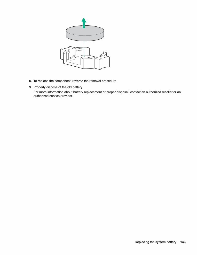
8. To replace the component, reverse the removal procedure.
9. Properly dispose of the old battery.For more information about battery replacement or proper disposal, contact an authorized reseller or anauthorized service provider.
Replacing the system battery 143
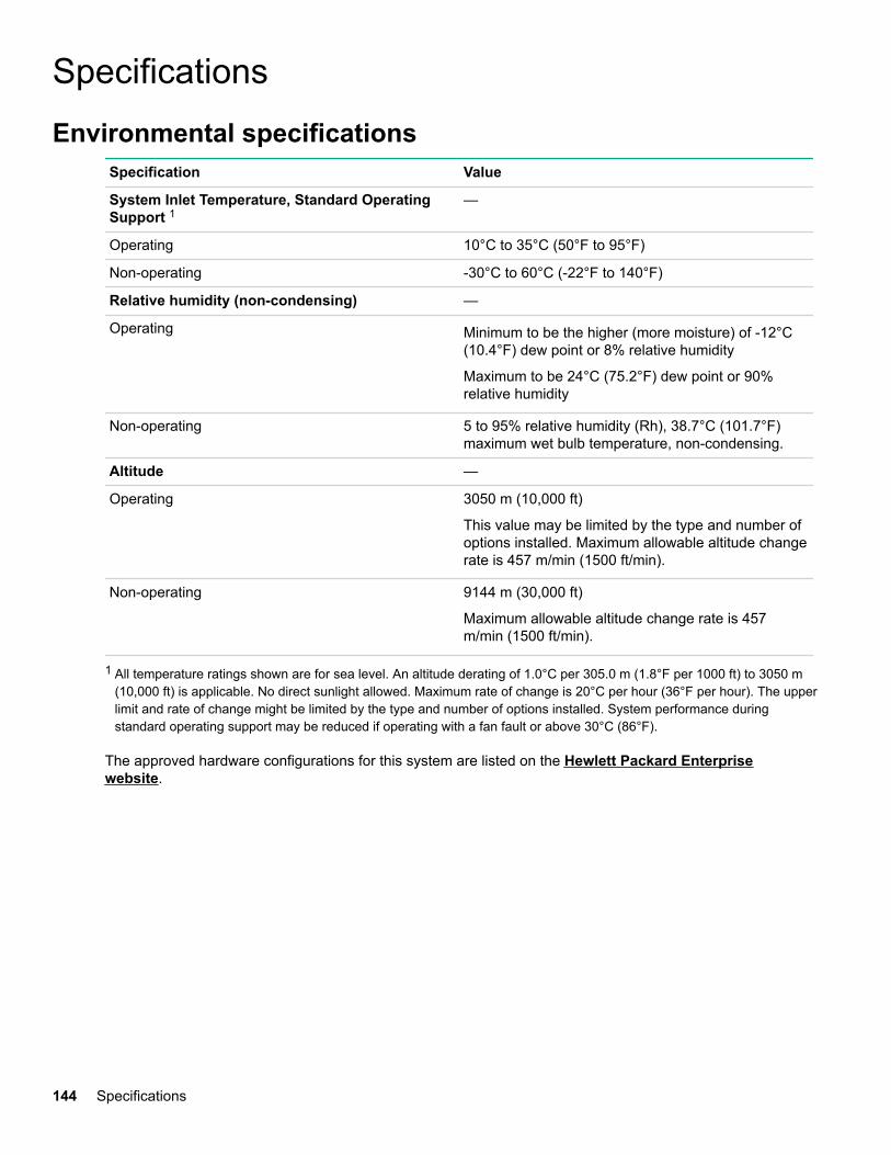
SpecificationsEnvironmental specifications
Specification Value
System Inlet Temperature, Standard OperatingSupport 1
—
Operating 10°C to 35°C (50°F to 95°F)
Non-operating -30°C to 60°C (-22°F to 140°F)
Relative humidity (non-condensing) —
Operating Minimum to be the higher (more moisture) of -12°C(10.4°F) dew point or 8% relative humidity
Maximum to be 24°C (75.2°F) dew point or 90%relative humidity
Non-operating 5 to 95% relative humidity (Rh), 38.7°C (101.7°F)maximum wet bulb temperature, non-condensing.
Altitude —
Operating 3050 m (10,000 ft)
This value may be limited by the type and number ofoptions installed. Maximum allowable altitude changerate is 457 m/min (1500 ft/min).
Non-operating 9144 m (30,000 ft)
Maximum allowable altitude change rate is 457m/min (1500 ft/min).
1 All temperature ratings shown are for sea level. An altitude derating of 1.0°C per 305.0 m (1.8°F per 1000 ft) to 3050 m(10,000 ft) is applicable. No direct sunlight allowed. Maximum rate of change is 20°C per hour (36°F per hour). The upperlimit and rate of change might be limited by the type and number of options installed. System performance duringstandard operating support may be reduced if operating with a fan fault or above 30°C (86°F).
The approved hardware configurations for this system are listed on the Hewlett Packard Enterprisewebsite.
144 Specifications
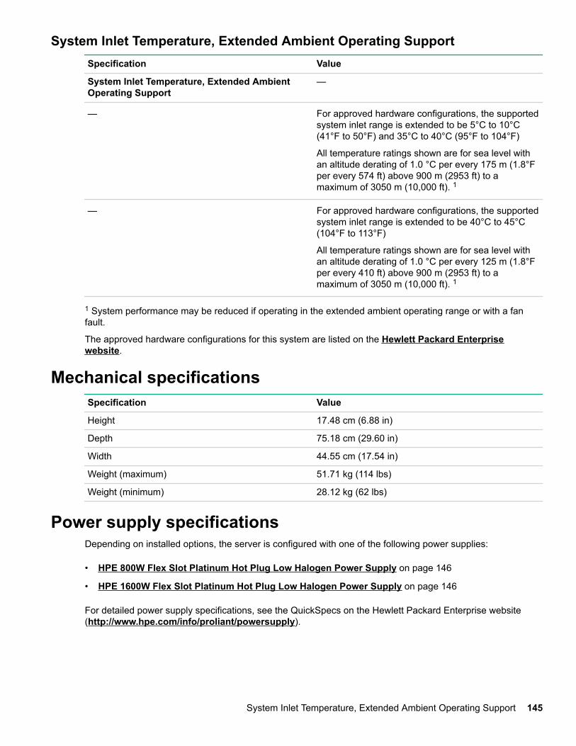
System Inlet Temperature, Extended Ambient Operating SupportSpecification Value
System Inlet Temperature, Extended AmbientOperating Support
—
— For approved hardware configurations, the supportedsystem inlet range is extended to be 5°C to 10°C(41°F to 50°F) and 35°C to 40°C (95°F to 104°F)
All temperature ratings shown are for sea level withan altitude derating of 1.0 °C per every 175 m (1.8°Fper every 574 ft) above 900 m (2953 ft) to amaximum of 3050 m (10,000 ft). 1
— For approved hardware configurations, the supportedsystem inlet range is extended to be 40°C to 45°C(104°F to 113°F)
All temperature ratings shown are for sea level withan altitude derating of 1.0 °C per every 125 m (1.8°Fper every 410 ft) above 900 m (2953 ft) to amaximum of 3050 m (10,000 ft). 1
1 System performance may be reduced if operating in the extended ambient operating range or with a fanfault.
The approved hardware configurations for this system are listed on the Hewlett Packard Enterprisewebsite.
Mechanical specificationsSpecification Value
Height 17.48 cm (6.88 in)
Depth 75.18 cm (29.60 in)
Width 44.55 cm (17.54 in)
Weight (maximum) 51.71 kg (114 lbs)
Weight (minimum) 28.12 kg (62 lbs)
Power supply specificationsDepending on installed options, the server is configured with one of the following power supplies:
• HPE 800W Flex Slot Platinum Hot Plug Low Halogen Power Supply on page 146
• HPE 1600W Flex Slot Platinum Hot Plug Low Halogen Power Supply on page 146
For detailed power supply specifications, see the QuickSpecs on the Hewlett Packard Enterprise website(http://www.hpe.com/info/proliant/powersupply).
System Inlet Temperature, Extended Ambient Operating Support 145
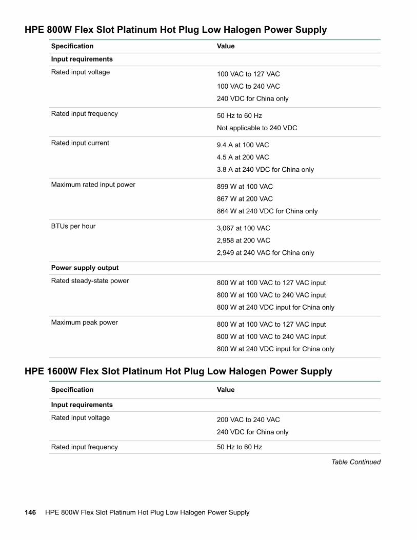
HPE 800W Flex Slot Platinum Hot Plug Low Halogen Power SupplySpecification Value
Input requirements
Rated input voltage 100 VAC to 127 VAC
100 VAC to 240 VAC
240 VDC for China only
Rated input frequency 50 Hz to 60 Hz
Not applicable to 240 VDC
Rated input current 9.4 A at 100 VAC
4.5 A at 200 VAC
3.8 A at 240 VDC for China only
Maximum rated input power 899 W at 100 VAC
867 W at 200 VAC
864 W at 240 VDC for China only
BTUs per hour 3,067 at 100 VAC
2,958 at 200 VAC
2,949 at 240 VAC for China only
Power supply output
Rated steady-state power 800 W at 100 VAC to 127 VAC input
800 W at 100 VAC to 240 VAC input
800 W at 240 VDC input for China only
Maximum peak power 800 W at 100 VAC to 127 VAC input
800 W at 100 VAC to 240 VAC input
800 W at 240 VDC input for China only
HPE 1600W Flex Slot Platinum Hot Plug Low Halogen Power Supply
Specification Value
Input requirements
Rated input voltage 200 VAC to 240 VAC
240 VDC for China only
Rated input frequency 50 Hz to 60 Hz
Table Continued
146 HPE 800W Flex Slot Platinum Hot Plug Low Halogen Power Supply
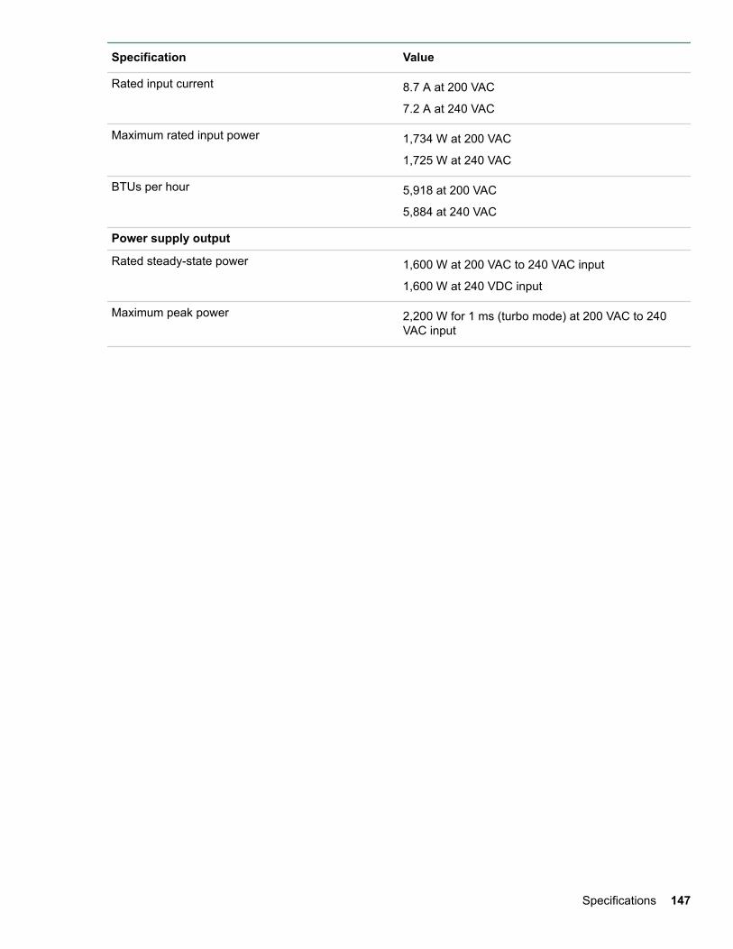
Specification Value
Rated input current 8.7 A at 200 VAC
7.2 A at 240 VAC
Maximum rated input power 1,734 W at 200 VAC
1,725 W at 240 VAC
BTUs per hour 5,918 at 200 VAC
5,884 at 240 VAC
Power supply output
Rated steady-state power 1,600 W at 200 VAC to 240 VAC input
1,600 W at 240 VDC input
Maximum peak power 2,200 W for 1 ms (turbo mode) at 200 VAC to 240VAC input
Specifications 147

WebsitesGeneral websitesHewlett Packard Enterprise Information Library
www.hpe.com/info/EILSingle Point of Connectivity Knowledge (SPOCK) Storage compatibility matrix
www.hpe.com/storage/spockStorage white papers and analyst reports
www.hpe.com/storage/whitepapers
For additional websites, see Support and other resources.
148 Websites
Support and other resources
Accessing Hewlett Packard Enterprise Support• For live assistance, go to the Contact Hewlett Packard Enterprise Worldwide website:
http://www.hpe.com/assistance
• To access documentation and support services, go to the Hewlett Packard Enterprise Support Centerwebsite:
http://www.hpe.com/support/hpesc
Information to collect
• Technical support registration number (if applicable)
• Product name, model or version, and serial number
• Operating system name and version
• Firmware version
• Error messages
• Product-specific reports and logs
• Add-on products or components
• Third-party products or components
Accessing updates• Some software products provide a mechanism for accessing software updates through the product
interface. Review your product documentation to identify the recommended software update method.
• To download product updates:
Hewlett Packard Enterprise Support Centerwww.hpe.com/support/hpesc
Hewlett Packard Enterprise Support Center: Software downloadswww.hpe.com/support/downloads
Software Depotwww.hpe.com/support/softwaredepot
• To subscribe to eNewsletters and alerts:
www.hpe.com/support/e-updates
• To view and update your entitlements, and to link your contracts and warranties with your profile, go to theHewlett Packard Enterprise Support Center More Information on Access to Support Materials page:
www.hpe.com/support/AccessToSupportMaterials
Support and other resources 149
IMPORTANT:
Access to some updates might require product entitlement when accessed through the Hewlett PackardEnterprise Support Center. You must have an HPE Passport set up with relevant entitlements.
Customer self repairHewlett Packard Enterprise customer self repair (CSR) programs allow you to repair your product. If a CSRpart needs to be replaced, it will be shipped directly to you so that you can install it at your convenience.Some parts do not qualify for CSR. Your Hewlett Packard Enterprise authorized service provider willdetermine whether a repair can be accomplished by CSR.
For more information about CSR, contact your local service provider or go to the CSR website:
http://www.hpe.com/support/selfrepair
Remote supportRemote support is available with supported devices as part of your warranty or contractual supportagreement. It provides intelligent event diagnosis, and automatic, secure submission of hardware eventnotifications to Hewlett Packard Enterprise, which will initiate a fast and accurate resolution based on yourproduct's service level. Hewlett Packard Enterprise strongly recommends that you register your device forremote support.
If your product includes additional remote support details, use search to locate that information.
Remote support and Proactive Care informationHPE Get Connected
www.hpe.com/services/getconnectedHPE Proactive Care services
www.hpe.com/services/proactivecareHPE Proactive Care service: Supported products list
www.hpe.com/services/proactivecaresupportedproductsHPE Proactive Care advanced service: Supported products list
www.hpe.com/services/proactivecareadvancedsupportedproducts
Proactive Care customer informationProactive Care central
www.hpe.com/services/proactivecarecentralProactive Care service activation
www.hpe.com/services/proactivecarecentralgetstarted
Warranty informationTo view the warranty for your product or to view the Safety and Compliance Information for Server, Storage,Power, Networking, and Rack Products reference document, go to the Enterprise Safety and Compliancewebsite:
www.hpe.com/support/Safety-Compliance-EnterpriseProducts
Additional warranty informationHPE ProLiant and x86 Servers and Options
www.hpe.com/support/ProLiantServers-Warranties
150 Customer self repair
HPE Enterprise Serverswww.hpe.com/support/EnterpriseServers-Warranties
HPE Storage Productswww.hpe.com/support/Storage-Warranties
HPE Networking Productswww.hpe.com/support/Networking-Warranties
Regulatory informationTo view the regulatory information for your product, view the Safety and Compliance Information for Server,Storage, Power, Networking, and Rack Products, available at the Hewlett Packard Enterprise Support Center:
www.hpe.com/support/Safety-Compliance-EnterpriseProducts
Additional regulatory information
Hewlett Packard Enterprise is committed to providing our customers with information about the chemicalsubstances in our products as needed to comply with legal requirements such as REACH (Regulation EC No1907/2006 of the European Parliament and the Council). A chemical information report for this product can befound at:
www.hpe.com/info/reach
For Hewlett Packard Enterprise product environmental and safety information and compliance data, includingRoHS and REACH, see:
www.hpe.com/info/ecodata
For Hewlett Packard Enterprise environmental information, including company programs, product recycling,and energy efficiency, see:
www.hpe.com/info/environment
Documentation feedbackHewlett Packard Enterprise is committed to providing documentation that meets your needs. To help usimprove the documentation, send any errors, suggestions, or comments to Documentation Feedback([email protected]). When submitting your feedback, include the document title, part number, edition,and publication date located on the front cover of the document. For online help content, include the productname, product version, help edition, and publication date located on the legal notices page.
Regulatory information 151