hse design engineering tutorial
TRANSCRIPT

© 2015 – Hervé Baron
HERVE BARON
Engineering Training
Welcome to this presentation.
It is part of a suite of Engineering training modules.
It shows the activities and deliverables of the Design Safety & Environment (HSE) discipline.
Comments are most welcome ([email protected]), which I will incorporate for the benefit of all.
Please download this file so that you can see my trainer’s notes in the top left corner – latest Acrobat Pro feature.
Hervé

© 2015 – Hervé Baron
HERVE BARON
Engineering disciplines: activities and deliverables
PROCESS
PLANT LAYOUT
EQUIPMENT
SAFETY & ENVIRONMENT
CIVIL
PIPING
PIPELINE
INSTRUMENTATION
ELECTRICAL

© 2015 – Hervé Baron
HERVE BARON
Design Safety
The “Design Safety” discipline is to safeguard against the PLANT hazards.
Where does PLANT hazard come from? Loss of containment
Which are the two ways Design Safety can safeguard against loss of containment?
Reduce possibility
Minimize effect
Give some examples of each

© 2015 – Hervé Baron
HERVE BARON
Design Safety
The “Design Safety” discipline is to safeguard against the PLANT hazards.
Where does PLANT hazard come from? Loss of containment

© 2015 – Hervé Baron
HERVE BARON
Design Safety
The “Design Safety” discipline is to safeguard against the PLANT hazards.
Where does PLANT hazard come from? Loss of containment
Which are the two ways Design Safety can safeguard against loss of containment?

© 2015 – Hervé Baron
HERVE BARON
Design Safety
The “Design Safety” discipline is to safeguard against the PLANT hazards.
Where does PLANT hazard come from? Loss of containment
Which are the two ways Design Safety can safeguard against loss of containment?
Reduce possibility
Minimize effect

© 2015 – Hervé Baron
HERVE BARON
Design Safety
The “Design Safety” discipline is to safeguard against the PLANT hazards.
Where does PLANT hazard come from? Loss of containment
Which are the two ways Design Safety can safeguard against loss of containment?
Reduce likelihood
Minimize effect
How?

© 2015 – Hervé Baron
HERVE BARON
Design Safety
The “Design Safety” discipline is to safeguard against the PLANT hazards.
Where does PLANT hazard come from? Loss of containment
Which are the two ways Design Safety can safeguard against loss of containment?
Reduce likelihood • QA and QC during design and construction • Detection of plant upsets • Overpressure protection • Pipes to be protected against mechanical failure as a result of vibration • Correct fail-safe position of control elements • Pipes to be sized to avoid hammering and surge • Minimize number of flanges • Explosion protection of Electrical Equipment and Instruments • Specify adequate Safety Integrity Level for Safety Automated Functions

© 2015 – Hervé Baron
HERVE BARON
Design Safety
The “Design Safety” discipline is to safeguard against the PLANT hazards.
Where does PLANT hazard come from? Loss of containment
Which are the two ways Design Safety can safeguard against loss of containment?
Reduce likelihood
Minimize effect
How?

© 2015 – Hervé Baron
HERVE BARON
Design Safety
The “Design Safety” discipline is to safeguard against the PLANT hazards.
Where does PLANT hazard come from? Loss of containment
Which are the two ways Design Safety can safeguard against loss of containment?
Reduce likelihood
Minimize effect • PLANT layout: isolation of ignition/leak sources, spacing between units
and equipment, bounding of liquid storage • Adequate personnel escape ways • Fire protection and fighting • Fire and Gas Detection and alarm • ESD system to isolate and depressurize
© 2015 – Hervé Baron
HERVE BARON
Design Safety
The “Design Safety” discipline is to safeguard against the PLANT hazards.
Where does PLANT hazard come from? Loss of containment
Which are the two ways Design Safety can safeguard against loss of containment?
Reduce possibility
Minimize effect
The different areas of involvement of Design Safety are defined in the Design Safety Philosophy, also called “Safety Concept”.
This presentation of the discipline will follow the table of content of this document

© 2015 – Hervé Baron
HERVE BARON
Design Safety Philosophy / Safety Concept
HAZARD Identification
Risk assessment
PLANT Layout
Process Safety Systems
Fire protection & Fire fighting
Fire & Gas Detection
Hazardous area classification
Escape, Evacuation

© 2015 – Hervé Baron
HERVE BARON
Design Safety Philosophy / Safety Concept
HAZARD Identification
Risk assessment
PLANT Layout
Process Safety Systems
Fire protection & Fire fighting
Fire & Gas Detection
Hazardous area classification
Escape, Evacuation

© 2015 – Hervé Baron
HERVE BARON
Design Safety Philosophy / Safety Concept
HAZARD Identification • General Hazards • Process related hazards

© 2015 – Hervé Baron
HERVE BARON
Design Safety Philosophy / Safety Concept
HAZARD Identification • General Hazards • Process related hazards
How are PLANT general hazards identified?

© 2015 – Hervé Baron
HERVE BARON
HAZard IDentification (HAZID)
A structured, key word based Qualitative risk identification and analysis methodology
Risk (to personnel safety, environment, assets) resulting from accident – normal operation excluded
Using check-lists enables a systematic screening.
Guided team brainstorming activity that benefits from the broad experience of a multidisciplinary team.
The result of the review is documented in a table where potential hazards, corresponding causes, consequences and associated safeguards are reported.
When necessary actions are formulated and followed-up

© 2015 – Hervé Baron
HERVE BARON
HAZard IDentification (HAZID) GUIDEWORDS

© 2015 – Hervé Baron
HERVE BARON
HAZard IDentification (HAZID)

© 2015 – Hervé Baron
HERVE BARON
HAZard IDentification (HAZID) Output

© 2015 – Hervé Baron
HERVE BARON
Design Safety Philosophy / Safety Concept
HAZARD Identification • General Hazards • Process related hazards

© 2015 – Hervé Baron
HERVE BARON
Design Safety Philosophy / Safety Concept
HAZARD Identification • General Hazards • Process related hazards
How are process hazards identified?

© 2015 – Hervé Baron
HERVE BARON
Hazard and Operability Review (HAZOP)
What is a HAZOP?

© 2015 – Hervé Baron
HERVE BARON
Hazard and Operability Review (HAZOP)
What is a HAZOP?
A review of the possible deviations of the process from normal conditions

© 2015 – Hervé Baron
HERVE BARON
Hazard and Operability Review (HAZOP)
What is a HAZOP?
A review of the possible deviations of the process from normal conditions
What are these possible deviations?

© 2015 – Hervé Baron
HERVE BARON
Hazard and Operability Review (HAZOP)
What is a HAZOP?
A review of the possible deviations of the process from normal conditions
What are these possible deviations?
High/Low Pressure, High/Low Temperature, High/Low Flow, change in composition

© 2015 – Hervé Baron
HERVE BARON
Hazard and Operability Review (HAZOP)
What is a HAZOP?
A review of the possible deviations of the process from normal conditions
What are these possible deviations?
High/Low Pressure, High/Low Temperature, High/Low Flow, change in composition
How does a HAZOP review proceed?

© 2015 – Hervé Baron
HERVE BARON
Hazard and Operability Review (HAZOP)
What is a HAZOP?
A review of the possible process deviations from normal conditions
What are these possible deviations?
High/Low Pressure, High/Low Temperature, High/Low Flow, change in composition
How does a HAZOP review proceed?
The plant is split in nodes. For each node, each deviation is reviewed.

© 2015 – Hervé Baron
HERVE BARON
Hazard and Operability Review (HAZOP)

© 2015 – Hervé Baron
HERVE BARON
Hazard and Operability Review (HAZOP)
What type of failure are reviewed in HAZOP?

© 2015 – Hervé Baron
HERVE BARON
Hazard and Operability Review (HAZOP)
What type of failure are reviewed in HAZOP? • Failure of process controls • Failure of equipment • Missoperation by operator

© 2015 – Hervé Baron
HERVE BARON
HAZOP action and response sheet

© 2015 – Hervé Baron
HERVE BARON
Action items follow-up

© 2015 – Hervé Baron
HERVE BARON
Design Safety Philosophy / Safety Concept
HAZARD Identification
Risk assessment
PLANT Layout
Process Safety Systems
Fire protection & Fire fighting
Fire & Gas Detection
Hazardous area classification
Escape, Evacuation

© 2015 – Hervé Baron
HERVE BARON
Safety of Layout

© 2015 – Hervé Baron
HERVE BARON
Safety of Layout
Where shall we locate the air-coolers electrical sub-station?
?

© 2015 – Hervé Baron
HERVE BARON
Safety of Layout

© 2015 – Hervé Baron
HERVE BARON
Design Safety Philosophy / Safety Concept
HAZARD Identification
Risk assessment
PLANT Layout
Process Safety Systems
Fire protection & Fire fighting
Fire & Gas Detection
Hazardous area classification
Escape, Evacuation

© 2015 – Hervé Baron
HERVE BARON
Design Safety Philosophy / Safety Concept
HAZARD Identification
Risk assessment
PLANT Layout
Process Safety Systems
Fire protection & Fire fighting
Fire & Gas Detection
Hazardous area classification
Escape, Evacuation
There are 2 types of Fire protection: Active and Passive. Give an example of each…

© 2015 – Hervé Baron
HERVE BARON
Fire Fighting
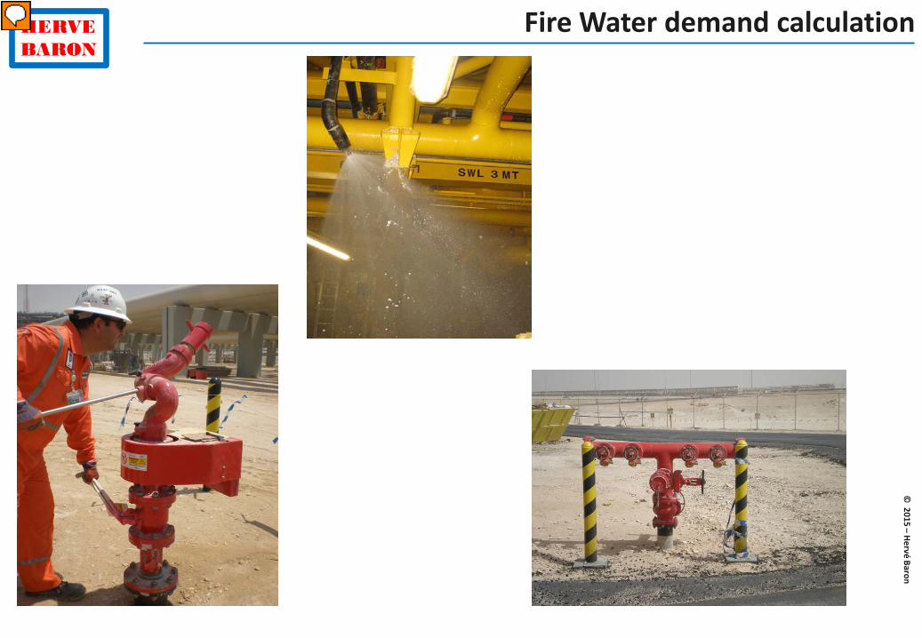
What type of fire fighting equipment uses water?
© 2015 – Hervé Baron
HERVE BARON
Fire Water demand calculation

© 2015 – Hervé Baron
HERVE BARON
Spray (deluge) system
What is the purpose of fixed water spray systems?

© 2015 – Hervé Baron
HERVE BARON
Spray (deluge) system
What is the purpose of fixed water spray systems? Which equipment are concerned?

© 2015 – Hervé Baron
HERVE BARON
Spray (deluge) system
Equipment to be protected by water spray system are not defined in codes but project wise, according to Client requirements if they exist or as per the Engineer’s choice, in the Job Specification for Design Active Fire Protection. Off-shore all equipment are deluged to cool down the equipment to limit the risk of fire escalation as equipment are very close to each other. On-shore fire fighting is much easier (access) and more space is provided between equipment. Hence a limited number of equipment are deluged. For instance: For fire intensity control: high hazard equipment that contain a severe fuel hazard with a high heat release rate thus requiring an immediate application of water, e.g., • All vessels, columns, heat exchangers holding more than 5 m3 LPG type hydrocarbon –
except equipment located at elevation of more than 8 meters. • Pumps handling LPG • HC close to their auto-ignition temperature • Compressors handling flammable gases – deluged area shall extend to auxiliaries
Exposure protection: e.g. “Equipment containing hydrocarbons which cannot be reached by firewater monitors.”

© 2015 – Hervé Baron
HERVE BARON
Fire Fighting
How do we calculate the Plant Fire water equirements?

© 2015 – Hervé Baron
HERVE BARON
Fire Fighting / Fire Zones

© 2015 – Hervé Baron
HERVE BARON
Fire Water demand calculation

© 2015 – Hervé Baron
HERVE BARON
Fire Water facilities

© 2015 – Hervé Baron
HERVE BARON
Fire Water distribution

© 2015 – Hervé Baron
HERVE BARON
Fire Water P&IDs

© 2015 – Hervé Baron
HERVE BARON
Deluge system arrangements

© 2015 – Hervé Baron
HERVE BARON
Fire protection and Personnel protection drawing

© 2015 – Hervé Baron
HERVE BARON
Passive fire protection
© 2015 – Hervé Baron
HERVE BARON
Passive fire protection

© 2015 – Hervé Baron
HERVE BARON
Passive fire protection

© 2015 – Hervé Baron
HERVE BARON
Passive fire protection
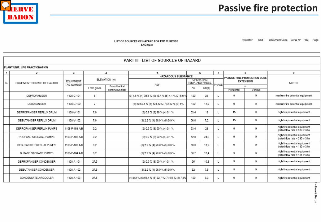
How are Fire envelopes defined? •A list of equipment creating a fire risk zone is drawn, generally, equipment containing more than 5m3 of liquid HC (as per codes, in, particular API 2218).
•This « list of source of hazard for PFP “ is not necessarily a deliverable, but an internal document
•Fire scenario envelopes around Equipment creating a Fire Hazard are drawn on a Plot Plan. Dimensions of envelopes are specified in the code (API 2218).
•Equipment inside the enveloppe are screened for requirement of Fire Proofing (criteria is that of code API RP 2218 ): flammable inventory or domino effect.

© 2015 – Hervé Baron
HERVE BARON
Design Safety Philosophy / Safety Concept
HAZARD Identification
Risk assessment
PLANT Layout
Process Safety Systems
Fire protection & Fire fighting
Fire & Gas Detection
Hazardous area classification
Escape, Evacuation

© 2015 – Hervé Baron
HERVE BARON
Design Safety Philosophy / Safety Concept
HAZARD Identification
Risk assessment
PLANT Layout
Process Safety Systems
Fire protection & Fire fighting
Fire & Gas Detection
Hazardous area classification
Escape, Evacuation
Where shall Emergency ShutDown Valves be provided?

© 2015 – Hervé Baron
HERVE BARON
Emergency Shutdown System (ESD)

© 2015 – Hervé Baron
HERVE BARON
Design Safety Philosophy / Safety Concept
HAZARD Identification
Risk assessment
PLANT Layout
Process Safety Systems
Fire protection & Fire fighting
Fire & Gas Detection
Hazardous area classification
Escape, Evacuation
© 2015 – Hervé Baron
HERVE BARON
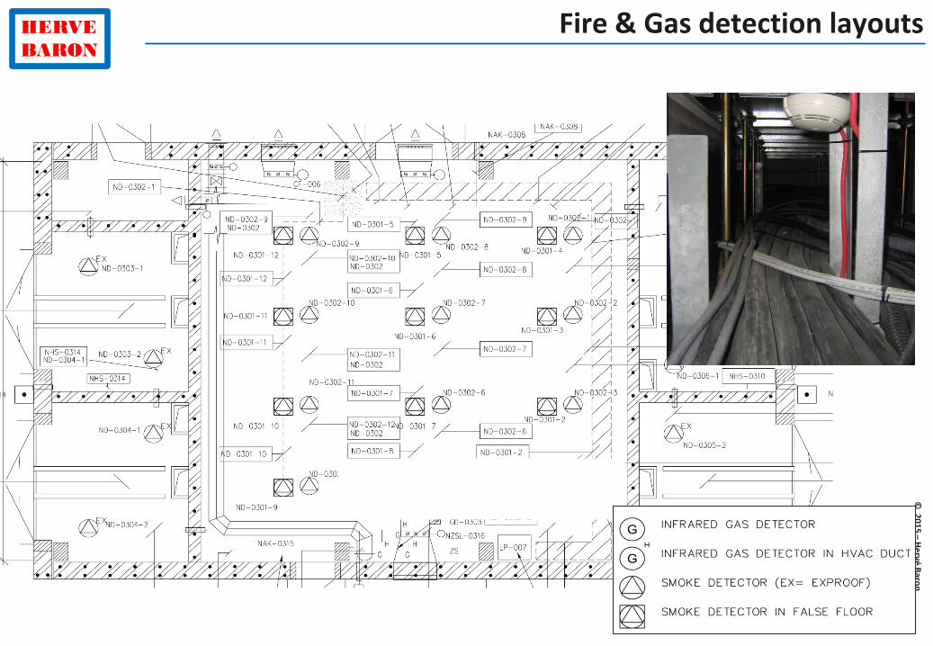
Fire & Gas detection layouts

© 2015 – Hervé Baron
HERVE BARON
Fire & Gas Cause & Effects matrix

© 2015 – Hervé Baron
HERVE BARON
Design Safety Philosophy / Safety Concept
HAZARD Identification
Risk assessment
PLANT Layout
Process Safety Systems
Fire protection & Fire fighting
Fire & Gas Detection
Hazardous area classification
Escape, Evacuation

© 2015 – Hervé Baron
HERVE BARON
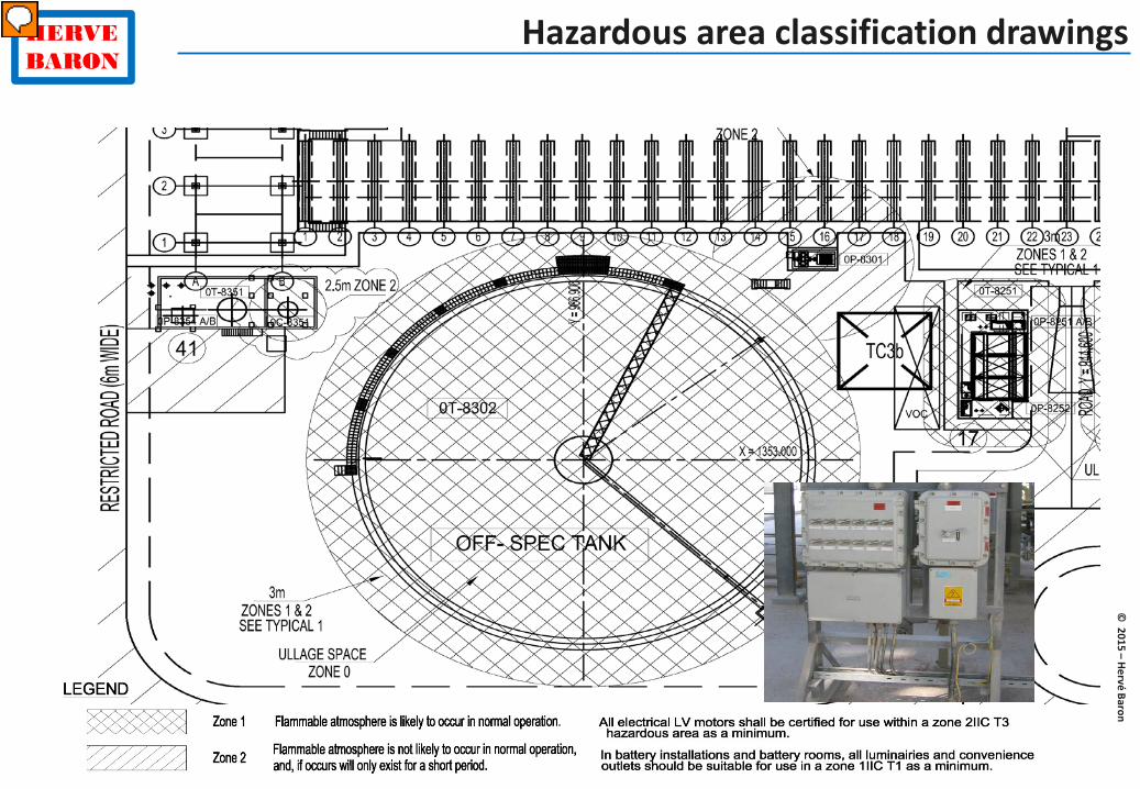
Hazardous area classification drawings

© 2015 – Hervé Baron
HERVE BARON
Hazardous area classification
The referential must be defined, e.g.,
API RP 505 Recommended Practices for Classification of Locations for Electrical Installations at Petroleum Facilities classified as Class I, Zone 0, Zone 1 and Zone 2 (1997 Edition).
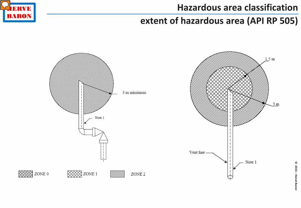
Zone 0 location is a location at which ignitible concentration of flammable gases or vapours are present continuously or for long periods of time.
Zone 1 location is a location at which ignitible concentration of flammable gases or vapours are likely to exist under normal operating conditions,
Zone 2 location is a location at which ignitible concentrations of flammable gases or vapours are not likely to occur in normal operation and if they do occur will exist only for a short period

© 2015 – Hervé Baron
HERVE BARON
Hazardous area classification
The Explosion protection of Electrical and Instrumentation equipment located in Hazardous area is defined by means of: Zone 0/1/2 - Gas Group - Temperature Class

© 2015 – Hervé Baron
HERVE BARON
Hazardous area classification
The Explosion protection of Electrical and Instrumentation equipment located in Hazardous area is defined by means of: Zone 1/2/3 - Gas Group - Temperature Class
© 2015 – Hervé Baron
HERVE BARON
Hazardous area classification extent of hazardous area (API RP 505)

© 2015 – Hervé Baron
HERVE BARON
Hazardous area classification extent of hazardous area (API RP 505)

© 2015 – Hervé Baron
HERVE BARON
Hazardous area classification extent of hazardous area (API RP 505)

© 2015 – Hervé Baron
HERVE BARON
Hazardous area classification extent of hazardous area (API RP 505)

© 2015 – Hervé Baron
HERVE BARON
Hazardous area classification extent of hazardous area (API RP 505)

© 2015 – Hervé Baron
HERVE BARON
Hazardous area classification
Why is the inside of the storage tank zone 1 for the tank on the left and zone 0 for the tank on the right?

© 2015 – Hervé Baron
HERVE BARON
Hazardous area classification drawings What is the use of the Hazardous area classification drawing?
© 2015 – Hervé Baron
HERVE BARON
Hazardous area classification drawings

© 2015 – Hervé Baron
HERVE BARON
Design Safety Philosophy / Safety Concept
HAZARD Identification
Quantitiative Risk Assessment (QRA)
PLANT Layout
Process Safety Systems
Fire protection & Fire fighting
Fire & Gas Detection
Hazardous area classification
Escape, Evacuation

© 2015 – Hervé Baron
HERVE BARON
Quantitative Risk Analysis (QRA)
Objective: Define the scenarios of likely loss of containment Content: Identify flammable, toxic fluids, isolatable sections Identify possible consequence: fire, explosion, toxic etc. Identify ignition source Input: PFD, HMB, Plot Plan HAZID Report
Step 0:
Failure cases definition

© 2015 – Hervé Baron
HERVE BARON
Quantitative Risk Analysis (QRA)
Step 0:
Failure Case Definition
Case : Gas leak from random piping component rupture
Cause: installation error, corrosion,
material defect…
Possible consequence: Dispersion without ignition / jet fire / flash fire / explosion
Section considered: Compressor building

© 2015 – Hervé Baron
HERVE BARON
Quantitative Risk Analysis (QRA)
Step 1:
Identification and characterisation of initiating events
Gas leak inside compressor buidling due to component rupture Hole size (% of component section)
5% 20% Full
Frequency (event/year) 1,11E-01 5,06E-04 6,83E-05
Outflow rate (kg/s) 5,7 90,8 2270,0
Σ risk components *failure rate (from statistics)
© 2015 – Hervé Baron
HERVE BARON
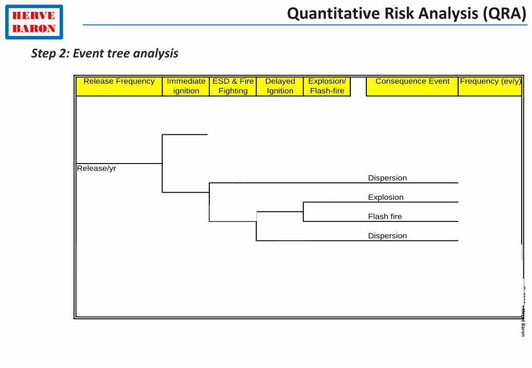
Quantitative Risk Analysis (QRA)
Release Frequency Immediate ignition
ESD & Fire Fighting
Delayed Ignition
Explosion/ Flash-fire
Consequence Event Frequency (ev/y)
0,998 Jet fire ESD & FF 7,779E-030,070
0,002 Jet fire no ESD & FF 1,520E-05
1,11E-01Release/yr
0,949 Dispersion 9,827E-020,930
0,120 Explosion 1,774E-050,028
0,051 0,880 Flash fire 1,301E-04
0,972 Dispersion 5,133E-03
Yes Frequency (event/year)Jet fire ESD & FF 7,779E-03Jet fire no ESD & FF 1,520E-05Explosion 1,774E-05
No Flash Fire 1,301E-04Dispersion 1,034E-01
B04a/b/c/d 5%
Step 2: Event tree analysis

© 2015 – Hervé Baron
HERVE BARON
Quantitative Risk Analysis (QRA)
Release Frequency Immediate ignition
ESD & Fire Fighting
Delayed Ignition
Explosion/ Flash-fire
Consequence Event Frequency (ev/y)
0,998 Jet fire ESD & FF 7,779E-030,070
0,002 Jet fire no ESD & FF 1,520E-05
1,11E-01Release/yr
0,949 Dispersion 9,827E-020,930
0,120 Explosion 1,774E-050,028
0,051 0,880 Flash fire 1,301E-04
0,972 Dispersion 5,133E-03
Yes Frequency (event/year)Jet fire ESD & FF 7,779E-03Jet fire no ESD & FF 1,520E-05Explosion 1,774E-05
No Flash Fire 1,301E-04Dispersion 1,034E-01
B04a/b/c/d 5%
Probability of immediate ignition for 1-50 kg/s release rate is 7% (from statistical data)
Gas detectors are provided inside the building, that activate isolation and depressurization. It is assumed that they operate 95% of the time.
Probability of explosion vs flash fire (12%) depends on mass of gas and degree of confinement
?
What is the frequency of an explosion?
Probability of delayed ignition (2.8%) takes into account equipment explosion protection (Ex)
Step 2: Event tree analysis

© 2015 – Hervé Baron
HERVE BARON
Quantitative Risk Analysis (QRA)
Possible consequences of loss of containment

© 2015 – Hervé Baron
HERVE BARON
Quantitative Risk Analysis (QRA)

© 2015 – Hervé Baron
HERVE BARON
Quantitative Risk Analysis (QRA)
Release Frequency Immediate ignition
ESD & Fire Fighting
Delayed Ignition
Explosion/ Flash-fire
Consequence Event Frequency (ev/y)
0,998 Jet fire ESD & FF 7,779E-030,070
0,002 Jet fire no ESD & FF 1,520E-05
1,11E-01Release/yr
0,949 Dispersion 9,827E-020,930
0,120 Explosion 1,774E-050,028
0,051 0,880 Flash fire 1,301E-04
0,972 Dispersion 5,133E-03
Yes Frequency (event/year)Jet fire ESD & FF 7,779E-03Jet fire no ESD & FF 1,520E-05Explosion 1,774E-05
No Flash Fire 1,301E-04Dispersion 1,034E-01
B04a/b/c/d 5%
Step 2: Event tree analysis

© 2015 – Hervé Baron
HERVE BARON
Quantitative Risk Analysis (QRA)
Overpresssure (bar) 0.2 0.1 0.01
Distance (m) 96 167 1270
Step 3:
Consequence evalutation
CONSEQUENCE CLASS QUANTITATIVE CRITERIA EFFECTS
MINOR ≤0.1 bar locally (within 10m) No effect, no damage
SIGNIFICANT ≤0.1 bar locally (within 50m) Limited damage to plant and operators
SEVERE > 0.1 bar within plant Damage to plant and operators
MAJOR > 0.1 bar on populated areas Damage to plant, operators & public

© 2015 – Hervé Baron
HERVE BARON
Quantitative Risk Analysis (QRA)
Unacceptable risk area– Design change necessary
As Low As Reasonably Practicable – Plant Management measures
Acceptable risk area ?
Final step:
classification of risk

© 2015 – Hervé Baron
HERVE BARON
Quantitative Risk Analysis (QRA)
Unacceptable risk area– Design change necessary
As Low As Reasonably Practicable – Plant Management measures
Acceptable risk area
1.0E-02
1.0E-03
1.0E-04 Unlikely
1.0E-05 Rare
1.0E-06 Minor Significant Severe Major
Final step:
classification of risk
Severity
Prob
abili
ty

© 2015 – Hervé Baron
HERVE BARON
Quantitative Risk Analysis (QRA)
Final step:
classification of risk
CONSEQUENCE CLASS QUANTITATIVE CRITERIA EFFECTS MINOR ≤0.1 bar locally (within
10m) No effect, no damage
SIGNIFICANT ≤0.1 bar locally (within 50m)
Limited damage to plant and operators
SEVERE > 0.1 bar within plant Damage to plant and operators MAJOR > 0.1 bar on populated
areas Damage to plant, operators & public
?

© 2015 – Hervé Baron
HERVE BARON
Quantitative Risk Analysis (QRA)
Final step:
classification of risk
CONSEQUENCE CLASS QUANTITATIVE CRITERIA EFFECTS MINOR ≤0.1 bar locally (within
10m) No effect, no damage
SIGNIFICANT ≤0.1 bar locally (within 50m)
Limited damage to plant and operators
SEVERE > 0.1 bar within plant Damage to plant and operators MAJOR > 0.1 bar on populated
areas Damage to plant, operators & public

© 2015 – Hervé Baron
HERVE BARON
Quantitative Risk Analysis (QRA)
CONSEQUENCE CLASS QUANTITATIVE CRITERIA EFFECTS MINOR ≤0.1 bar locally (within
10m) No effect, no damage
SIGNIFICANT ≤0.1 bar locally (within 50m)
Limited damage to plant and operators
SEVERE > 0.1 bar within plant Damage to plant and operators MAJOR > 0.1 bar on populated
areas Damage to plant, operators & public
Outcome?

© 2015 – Hervé Baron
HERVE BARON
Quantitative Risk Analysis (QRA)
QRA results: Thermal radiation map (>37.5 kW/m2)

© 2015 – Hervé Baron
HERVE BARON
Quantitative Risk Analysis (QRA)
QRA outcome: Risk Reduction Measures At FEED stage Explosion and fire radiation curves:
Distance between units, e.g., distance between process units and administration buildings, relocation of CCR etc.
Explosion resistance and fire rating of equipment, manned buildings, structures (design for 10-4 per year likelihood: API RP 752 ; ISO19901-3 ; NORSOK Z-013, …)
At Detail Design Stage
Addition of gas detectors Addition of blast/fire protection wall, e.g., between process and utility modules, for
protection of risers ESDV valves Relocation of muster point Relocation of adjacent human occupancy areas (maintenance yard, highway rest area etc.) Recommendation for operations, e.g., increased inspection

© 2015 – Hervé Baron
HERVE BARON
Quantitative Risk Analysis (QRA)
HAZARD Identification
Quantitiative Risk Assessment (QRA) • Failure cases identification and definition • Consequence Analysis • Frequency Analysis • QRA Outcome
© 2015 – Hervé Baron
HERVE BARON
Quantitative Risk Analysis (QRA)
HAZARD Identification
Quantitiative Risk Assessment (QRA) • Failure cases identification and definition • Consequence Analysis • Frequency Analysis • QRA Outcome
Another example: toxic gas release

© 2015 – Hervé Baron
HERVE BARON
Quantitative Risk Analysis (QRA) Consequence analysis

© 2015 – Hervé Baron
HERVE BARON
Quantitative Risk Analysis (QRA) Consequence analysis
What conclusion would you draw?

© 2015 – Hervé Baron
HERVE BARON
Quantitative Risk Analysis (QRA)
HAZARD Identification
Quantitiative Risk Assessment (QRA) • Failure cases identification and definition • Consequence Analysis • Frequency Analysis • QRA Outcome
Another example: effect of congestion

© 2015 – Hervé Baron
HERVE BARON
Quantitative Risk Analysis (QRA)
HAZARD Identification
Quantitiative Risk Assessment (QRA) • Failure cases identification and definition • Consequence Analysis
VCE: a flammable gas or a flashing liquid released to atmosphere, if not immediately ignited, disperses to atmosphere creating a cloud which can develop in a Vapour Cloud Explosion (VCE), if the burning velocity of the cloud is increased due to turbulence generated by obstacles present in the cloud. Effects (damages) are associated to levels of overpressure generated by pressure wave.
Explosion strength depends on level of congestion. Congested areas are identified based on arrangement of equipment/group of equipment,
platforms, and structures within each Process Unit. Air coolers / pipe-racks / compressor shelters are considered as roofs underneath which gas
cloud can accumulate. Free areas between group of equipment within Process Unit reduce the size of the congested
areas. Flammable volume/mass is estimated for each unitary congested area.

© 2015 – Hervé Baron
HERVE BARON
Quantitative Risk Analysis (QRA)
Identification of congested areas

© 2015 – Hervé Baron
HERVE BARON
Quantitative Risk Analysis (QRA)

© 2015 – Hervé Baron
HERVE BARON
COMPANY Societal Risk Criteria
1.0E-8
1.0E-7
1.0E-6
1.0E-5
1.0E-4
1.0E-3
1.0E-2
1 10 100 1000 Number of Fatalities (N or more)
Freq
uenc
y (/y
r)
Intolerable above line Acceptable below line
ALARP Region

© 2015 – Hervé Baron
HERVE BARON
Design Safety Philosophy / Safety Concept
HAZARD Identification
Risk assessment
PLANT Layout
Process Safety Systems
Fire protection & Fire fighting
Fire & Gas Detection
Hazardous area classification
Escape, Evacuation

© 2015 – Hervé Baron
HERVE BARON
Escape, evacuation

© 2015 – Hervé Baron
HERVE BARON
Escape, evacuation

© 2015 – Hervé Baron
HERVE BARON
Engineering disciplines: activities and deliverables
PROCESS
PLANT LAYOUT
EQUIPMENT
SAFETY & ENVIRONMENT
CIVIL
PIPING
PIPELINE
INSTRUMENTATION
ELECTRICAL

© 2015 – Hervé Baron
HERVE BARON
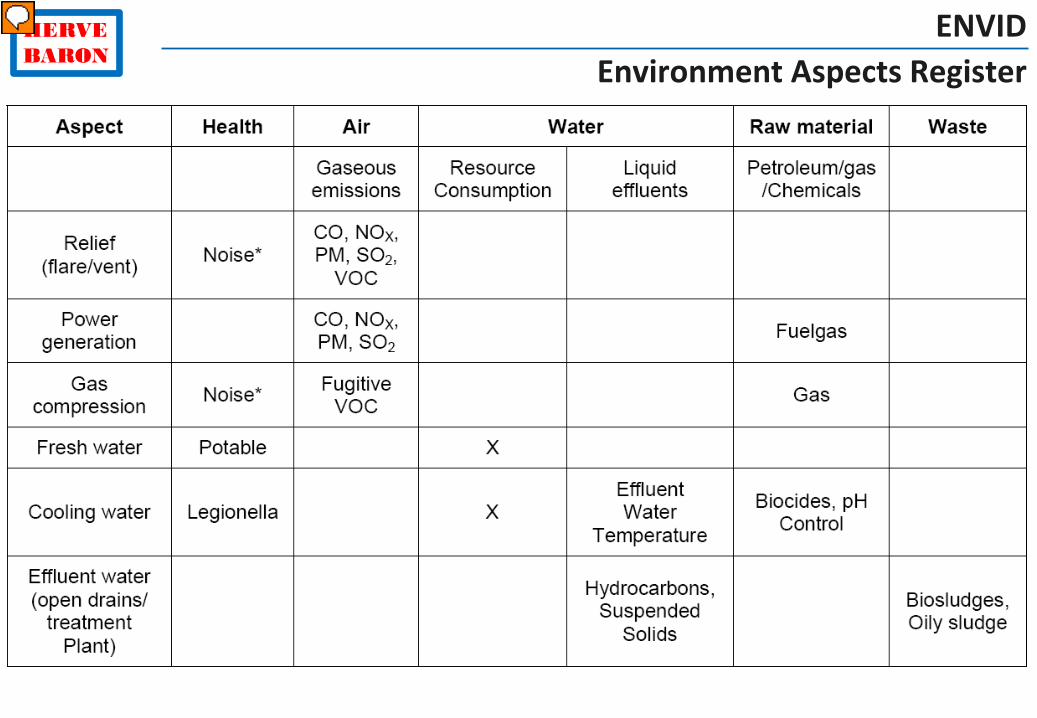
Health and Environment Requirements Job Specification for Design
Environmental and health aspects
Regulatory requirements
Air emissions
Liquid effluents
Soil & groundwater contamination
Wastes
Pollution prevention
Noise

© 2015 – Hervé Baron
HERVE BARON
Health and Environment Requirements Job Specification for Design
Environmental and health aspects
Regulatory requirements
Air emissions
Liquid effluents
Soil & groundawter contamination
Wastes
Pollution prevention
Noise
© 2015 – Hervé Baron
HERVE BARON
ENVID Environment Aspects Register

© 2015 – Hervé Baron
HERVE BARON
Environment Emissions regulatory limits

© 2015 – Hervé Baron
HERVE BARON
Environmental Impact Assessment

© 2015 – Hervé Baron
HERVE BARON
Noise study
dB(A)

© 2015 – Hervé Baron
HERVE BARON
The Oil & Gas Engineering Guide
Get all this plus the same on other disciplines and the overall picture... in the newly published:

© 2015 – Hervé Baron
HERVE BARON
The Oil & Gas Engineering Guide - 2nd edition
Table of Contents
© 2015 – Hervé Baron
HERVE BARON
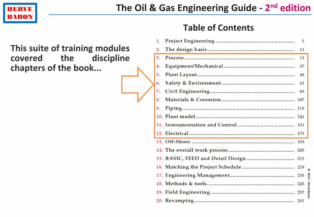
The Oil & Gas Engineering Guide - 2nd edition
Table of Contents
This suite of training modules covered the discipline chapters of the book...

© 2015 – Hervé Baron
HERVE BARON
The Oil & Gas Engineering Guide - 2nd edition
Table of Contents
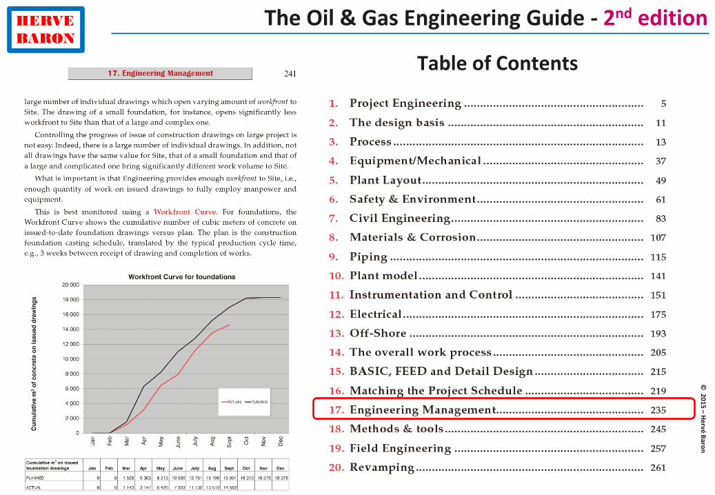
The Guide contains much more:
The overall picture, interfaces, methods & tools, etc.

© 2015 – Hervé Baron
HERVE BARON
The Oil & Gas Engineering Guide - 2nd edition
Table of Contents

© 2015 – Hervé Baron
HERVE BARON
The Oil & Gas Engineering Guide - 2nd edition
Table of Contents
© 2015 – Hervé Baron
HERVE BARON
The Oil & Gas Engineering Guide - 2nd edition
Table of Contents

© 2015 – Hervé Baron
HERVE BARON
The Oil & Gas Engineering Guide 2nd edition
Order direct from the publisher:
http://www.editionstechnip.com/en/catalogue-detail/1111/oil-gas-engineering-guide-the.html