hsl-lta/lts alcoa light tester pneumatic reject control ... · hsl-lta/lts alcoa light tester...
TRANSCRIPT
HSL-LTA/LTS ALCOA Light Tester
Pneumatic Reject Control User’s Manual
Systems Engineering Associates, Inc. 14989 West 69th Avenue Arvada, Colorado 80007 U.S.A. Telephone: (303) 421-0484 Fax: (303) 421-8108 www.sea-seg.com 02/2004

HSL-LTA/LTS ALCOA Light Tester
Pneumatic Reject Control User’s Manual
Revised 16 February 2004
Copyright © 2001 Systems Engineering Associates, Inc.
All Rights Reserved!

WARNING To ensure the equipment described by this User Manual, as well as the equipment connected to and used with it, operates satisfactorily and safely, all applicable local and national codes that apply to installing and operating the equipment must be followed. This includes the National Electric Code in the USA and other applicable legislation, regulations, and codes in practice elsewhere. Since codes can vary geographically and can change with time, it is the user’s responsibility to determine which standards and codes apply, and to comply with them. FAILURE TO COMPLY WITH APPLICABLE CODES AND STANDARDS CAN RESULT IN DAMAGE TO EQUIPMENT AND/OR SERIOUS INJURY TO PERSONNEL. Persons supervising and performing installation or maintenance must be suitably qualified and competent in these duties, and should carefully study this User Manual and any other manuals referred to by it prior to installation and/or operation of the equipment. _____________________________________________________________________________
_ The contents of the User Manual are believed to be correct at the time of printing; however, no responsibility is assumed for inaccuracies. In the interests of a commitment to a policy of continuous development and improvement, the manufacturer reserves the right to change the specification of the product or it’s performance or the contents of the User Manual without notice. _____________________________________________________________________________
_
Copyright © 2001 Systems Engineering Associates, Inc.
All Rights Reserved !

CONTENTS
1. General Description 1 1.1 Features 1 1.2 Functional Description 2 1.3 Leaker Reject Blow-off System 3 1.4 Vision Inspection System Reject 4 1.5 Data Collection 4 1.6 Tester Requirements 5 2. Installation 7 2.1 What's Included 7 2.2 Services Required 7 2.3 Pre-Installation 8 2.4 Installation (Down Day) 9 2.5 Set-up 11 2.6 HSMLT Set-up Software Installation 15 2.6.1 Windows Installation 15 2.6.2 DOS Installation 16
2.7 SYSdev Program Development Software Installation 17 2.8 HSMLT Application Program Installation 18 2.9 Modify Existing PLC Program 19 2.10 Set-up Reference 21 2.10.1 Default Set-up Variables (LT-10) 21 2.10.2 Default Set-up Variables (LT-12) 21 2.10.3 Default Set-up Variables (LT-16) 22 2.10.4 Machine Zero 22 2.10.5 Machine Timing Signals 23 2.10.6 FIFO Error Correction Calibration 23 2.10.7 View Critical Input Positions Menu 26
2.11 HSMLT Module Replacement 26 3. Using the Keypad/Display 29 3 1 Default Screen 30 3.2 "Rejects per Pocket” Key 30 3.3 "Current Shift" Key 31 3.4 "Last Shift” Key 31 3.5 "Set-up" Key 32 3.5.1 Set Reject Shift Registers 33 3.5.2 Set Reject Blow-off Parameters 34 3.5.3 Set Machine Timing (Set-Points, etc.) 35 3.5.4 Zero Machine (Set Resolver Offset) 36 3.5.5 Calibrate FIFO Error Detection 36 3.5.6 View Critical Input Positions 37 3.5.7 Set Keypad/Display "Set-Up" Key Passcode 37
3.6 "Test Blow-off" Key 38
HSL-LTA/LTS User’s Manual SYSTEMS Electronics Group
- i -
CONTENTS
4. HSMLT Windows Based Set-up Program Reference 39 4.1 General Description 40 4.2 The File Menu 43 4.2.1 The Set-Up Data File 44 4.2.2 Upload (save) Data 45 4.2.3 Download Program 46 4.2.4 Download (restore) Data 48 4.2.5 Print Report 48
4.3 The Edit Menu 49 4.3.1 Enable Offline Editing 50 4.3.2 Setup Comm Port 50 4.3.3 Edit Set-Up Passcode 51
4.4 The View Menu 52 4.4.1 Target Board Interface 53 4.4.2 View Online Data 54 4.4.3 View Offline Data 54 4.5 The Window Menu 55 4.5.1 The Main Display Window 56 4.5.2 The Setup Parameters Window 57 4.5.3 The Serial Communications Window 67 4.5.4 The Shift Data Window 70 4.5.5 The I/O States Window 74 5. HSMLT DOS Based Set-Up Program Reference 75 5.1 Main Menu 75 5.2 Reject Setup Parameters 76 1: Set Reject Shift Registers 76 2: Set Can Neck Size 77 3: Set Blow-off Solenoid Parameters 77 4: Set Machine Timing 77 5.3 Number of Rejects per Pocket Data 78 5.4 Current Shift Data 79 5.5 Last Shift Data 80 5.6 Download Program to Module 81 5.7 Download Set-up Data to Module 82 5.8 Upload (save) Set-up Data from Module 83
HSL-LTA/LTS User’s Manual SYSTEMS Electronics Group
- ii -
CONTENTS
6. Trouble-shooting 85 6.1 HSMLT Alarm Message Definitions 85 6.2 Can Tracking Errors Trouble-shooting 87 6.3 Can Reject Problems Trouble-shooting 91 7. Recommended Spares 95
LIST OF FIGURES
Keypad/Display Legend 29
APPENDICES
Allen-Bradley DF1 Communications Appendix A Hardware A-1 Software A-3 Using the MSG Instruction A-5 Channel 0 Setup A-9 Read/Write Data Definitions A-12 Drawings Appendix B
HSL-LTA/LTS User’s Manual SYSTEMS Electronics Group
- iii -

SECTION 1 GENERAL DESCRIPTION
This section describes the features of the HSL-LTA and HSL-LTS (hereafter referred to as the HSL-LTA/LTS) Alcoa (Borden's) Light Tester electronic reject control packages. This includes the functional description, alarms detected, etc. This manual applies to both aluminum can (HSL-LTA) and steel can (HSL-LTS) packages. The difference between the packages is the method of pneumatic rejection. Otherwise the packages function the same. ________________________________________________________ 1.1 FEATURES
Replaces existing odd/even mechanical reject mechanism with a reject blow-off solenoid assembly mounted in the discharge of the light tester to reject defective cans. Proprietary logic tracks cans from the leak detection array receiver to the reject blow-off location in the discharge and accurately rejects leaker cans at all speeds.
•
•
•
•
•
•
Performs high speed control functions of Alcoa Light Tester to speeds in excess of 3000 CPM (machine mechanically permitting). This includes detection of leaker cans (interfaces with existing Leak detection arrays), rejection of leaker cans, alarm detection as well as data acquisition.
Optionally excepts reject input from Vision inspection systems to incorporate rejection of inspected cans with leaker reject blow-off solenoid as well.
High speed front-end upgrade package which interfaces with existing control system.
Alarm detection: leak detection array fault, tester discharge can jam/back-up, timing signal fail, can presence sensor fail, photo eye lenses dirty fault, and missed reject detection.
Data Acquisition: Total number of good cans tested, total number of leaker rejects, total number of vision rejects, total rejects per pocket, etc. (for both current shift and last shift).
HSL-LTA/LTS User’s Manual SYSTEMS Electronics Group
- 1 -
SECTION 1 GENERAL DESCRIPTION
Built-in 2 Line X 40 character sealed display with 24 key membrane keypad allows local viewing of collected data (can count, reject count, rejects per pocket) by operator and set-up of all user variables (passcode protected or key switch enabled) by authorized personnel.
•
•
•
Interfaces directly with machine mounted resolver, existing leak detection array receiver, can presence sensor, reject photo eye and reject blow-off solenoid.
Based on high performance M4503 PLC/PLS module allowing easy trouble-shooting and user customization using SYSdev (DOS-based) programming package.
________________________________________________________ 1.2 FUNCTIONAL DESCRIPTION The HSL-LTA/LTS Alcoa (Borden's) Light Tester electronic reject control package is an electronic upgrade for the Borden's Light Tester which replaces the existing mechanical odd/even reject mechanism with a tester discharge mounted reject blow-off solenoid thus allowing significant increases in speed. The package interfaces to the existing leak detection array receiver, tracks leaker cans from the receiver to the blow-off location in the tester discharge, and accurately rejects the leaker cans regardless of machine speed. In addition, the package can be used to reject cans inspected from vision inspection systems and blow any inspected reject cans from the same reject blow-off port. Alarm detection is provided including: leak detection array fault, can jam/back-up at discharge, timing signal failure, excessive lo/hi FIFO corrections, blow-off photo eye lenses dirty fault, missed reject detection and can presence sensor fail. Data collection includes: Total number of good cans tested, total number of leaker rejects, total number of vision rejects, rejects per pocket, etc. (both for the current shift and previous (last) shift). The package interfaces directly to the machine mounted resolver, existing leak detection array receiver, can presence sensor, reject photo eye and reject blow-off solenoid as well as the host PLC via discrete DC I/O.
HSL-LTA/LTS User’s Manual SYSTEMS Electronics Group
- 2 -
SECTION 1 GENERAL DESCRIPTION
The package is not a dedicated "black box", but is instead implemented using the high performance SYSTEMS M4503 PLC/PLS module allowing easy customization by either SEA or the end user. The M4503 module is programmed using the DOS-based SYSdev programming package allowing the module to be programmed in any combination of Ladder or High-level (subset of "C"), as well as perform on-line monitoring and trouble-shooting. The M4503 module incorporates a built-in PLS which interfaces directly with the machine-mounted resolver and provides all machine timing, eliminating the need for an external PLS. ________________________________________________________ 1.3 LEAKER REJECT BLOW-OFF SYSTEM The package incorporates a reject blow-off assembly, which is mounted in the discharge of the tester, to reject detected leak cans. This replaces the existing mechanical odd/even reject mechanism thus allowing significant increases in speed. The package interfaces to the existing leak detection array receiver, tracks leaker cans from the receiver to the blow-off location in the discharge, and accurately rejects the leaker cans regardless of machine speed. By eliminating the existing mechanical reject mechanism, limitations of machine speed relating to the response time of the mechanical reject are eliminated. The blow-off reject system is capable of accurately rejecting cans at speeds in excess of 3000 CPM. The discharge reject blow-off assembly consists of a bracket equipped with two high-speed blow-off solenoids and a fiber optic photo eye. This is mounted at the discharge of the tester immediately following the discharge star-wheel. The existing encoder is replaced with a resolver to provide the additional timing required. A can presence sensor mounted in the discharge starwheel, along with the resolver and existing leak detection array receiver are used to track the cans to the discharge of the machine. The leaker cans are then rejected from the machine using the blow-off photo eye to accurately activate the reject solenoid regardless of machine speed.
HSL-LTA/LTS User’s Manual SYSTEMS Electronics Group
- 3 -

SECTION 1 GENERAL DESCRIPTION
________________________________________________________ 1.4 VISION INSPECTION SYSTEM REJECT The package can except a reject signal from a vision inspection system and reject these cans with the same reject blow-off solenoid. The vision system reject signal must occur between the infeed load location on the tester and the discharge of the tester. The vision reject signal must also be in sync with the machine. ________________________________________________________ 1.5 DATA COLLECTION The following data is collected for both the current shift and the previous (last) shift:
1) Total number of good cans tested 2) Total number of leaker rejects 3) Total number of vision inspection rejects 4) Total leaker rejects per pocket (for each pocket)
This data can be viewed locally on the display. This information is updated ("current" shift transferred to "Last" shift) based on the change of state of a discrete input. This input can be activated on an 8 or 12 hour shift basis or alternatively activated manually on a label run basis depending on the user's preference. This data is also available to the host PLC via discrete count outputs. In addition to the shift data collection, a separate buffer is available to collect rejects per pocket counts as a diagnostics aid to the operator for trouble-shooting a bad seal on a specific pocket. Unlike the shift data, these counts can be reset manually by the operator at will. This allows the operator to note an abnormally high count on a specific pocket, attempt to correct the problem, reset the counts and then recheck the counts to determine if the problem still persists.
HSL-LTA/LTS User’s Manual SYSTEMS Electronics Group
- 4 -
SECTION 1 GENERAL DESCRIPTION
________________________________________________________ 1.6 TESTER REQUIREMENTS The reject blow-off assembly is mounted in the discharge track-work at the immediate exit of the tester. Thus certain installation requirements must be met in order to implement the system. Aluminum Can Installations (HSL-LTA): For machines testing aluminum cans, the can is rejected up and out of the discharge track-work into a reject chute. This requires a straight section of track-work 18” long from where the track-work mates to the tester discharge. An opening in the top of this 18” length of track-work is made for a reject clearance and to mount a discharge funnel plate. For air tunnels, the upper lips of the air tunnel must be cut off, welded to the plenum, and ground flush. For gravity track-work, the upper half-round rails are cut-off. In either case, either a new reject chute is manufactured or the existing reject chute is modified to interface with the new reject blow-off system. Steel Can Installations (HSL-LTS): For machines testing steel cans, the can is rejected down off a magnetic conveyor located at the discharge of the tester. If the tester does not already have a magnetic conveyor at the immediate tester exit (such as a gravity track instead), one will have to be added. Note: The magnetic conveyor must start immediately from the discharge of the tester. The reject blow-off assembly is mounted on this magnetic conveyor and blows the can down, either into a reject chute or bucket. The magnetic conveyor is supplied by the customer and is not provided as part of the HSL-LTS package. For both the aluminum and steel can installations, labor and material to modify the discharge track-work/conveyor and manufacture or modify the reject chute is not provided as part of the HSL-LTA/LTS packages. This is supplied by the customer.
HSL-LTA/LTS User’s Manual SYSTEMS Electronics Group
- 5 -

SECTION 1 GENERAL DESCRIPTION
(This Page Intentionally Left Blank)
HSL-LTA/LTS User’s Manual SYSTEMS Electronics Group
- 6 -
SECTION 2 INSTALLATION
The HSL-LTA/LTS enclosure is provided for wall mounting in the vicinity of the existing user's control cabinet or tester. ________________________________________________________ 2.1 WHAT'S INCLUDED Verify that the following items are included when unpacking the HSL-LTA/LTS:
1ea. HSL-LTA/LTS Enclosure (14" X 12" X 8") with HSMLT Reject Control Module.
1ea. BRK-LTB-SOL Reject Blow-off Assembly with blow-off solenoid and Fiber Optic Photo Eye.
1ea. BRK-LTB-PRX Can Presence Sensor Assembly. 1ea. BRK-LTB-HD Hardware Kit 1ea. RSV34-MS1 Resolver 1ea. RSV-RSCBLE-100 Resolver Cable 1ea. HSL-LTA/LTS User's Manual 1ea. M4500 User's Manual 1ea. HSL-LTA/LTS Program Disk
________________________________________________________ 2.2 SERVICES REQUIRED Electrical Power: The HSL-LTA/LTS is powered from 115VAC/230VAC 50/60HZ at 2.0/1.0 Amps and +24VDC at 2.0 Amps. The 115VAC/230VAC is used to power the HSMLT module while the +24VDC is used to power the +24VDC I/O (sensors and blow-off solenoid). The +24VDC current required by the HSL-LTA/LTS is no more than the existing systems +24VDC current requirement, therefore the existing +24VDC power supply should be adequate. Compressed Air: Compressed Air is used for the reject blow-off. Clean dry air at 90 to 110 psi, 0.25 SCFM is required.
HSL-LTA/LTS User’s Manual SYSTEMS Electronics Group
- 7 -
SECTION 2 INSTALLATION
________________________________________________________ 2.3 PRE-INSTALLATION The following should be performed, by the customer, prior to the maintenance (down) day: Mechanical: 1) If necessary, manufacture new reject chute to be compatible with
pneumatic reject system (refer to appropriate aluminum or steel detail at the back of this manual).
Electrical: 1) Mount the HSL-LTA/LTS 14” X 12” X 8” enclosure. This can be
mounted wherever is convenient for the plant; on the light tester, on the existing control cabinet, or somewhere else close to the tester that is convenient for operator access.
2) Run conduit between the HSL-LTA/LTS enclosure, existing
control cabinet, and light tester. Refer the interconnect diagram at the back of this manual.
3) Pull wire between the enclosure, existing control cabinet, and
light tester as outlined in the interconnect diagram at the back of this manual.
4) Terminate the wires in the HSL-LTA/LTS enclosure. 5) Configure the BRK-LTB-SOL Reject Assembly for the particular
discharge configuration of the light tester if not already done so. 6) Make a copy of the existing control system program and modify it
to interface with the HSL-LTA/LTS (see section 2.9).
HSL-LTA/LTS User’s Manual SYSTEMS Electronics Group
- 8 -
SECTION 2 INSTALLATION
________________________________________________________ 2.4 INSTALLATION (DOWN DAY) The following must be performed with the machine stopped and power “off”. Thus this is usually performed on a scheduled maintenance day. The following consists of both mechanical and electrical tasks performed by plant personnel or contractors: Mechanical: 1) Aluminum can installations:
a) Modify discharge track-work to provide an 18” opening in the upper portion of the discharge track-work to allow rejection of bad cans (see “Aluminum Discharge Detail” at the back of this manual). For air tunnels, the upper lips of the air tunnel will have to be cut-off and the plenum welded and ground to the steel air tunnel. For gravity discharge track-works, the upper half-rounds will have to be cut-off.
b) Mount funneling plate (provided) in last 10” of 18” cut-out of
discharge track-work (see “Aluminum Discharge Detail” at the back of this manual).
2) Mount and pipe the Reject Assembly (refer to appropriate
aluminum or steel detail drawing). In general, the air lines from the reject solenoids to the manifold or nozzle must be less than 4”. On aluminum installations, the face of the manifold should not be closer than 1/4” from the can (see figure 2 of the aluminum detail drawing).
3) Remove middle and lower discharge guide rails and mount Reject
Fiber-optic sensors to rails as shown in “Discharge Detail” at the back of this manual. Ground off the welded spacers from the rails where the sensors will mount and drill a clearance hole in each rail for the 2nd mounting hole of the sensor bracket. Bolt one sensor to each bracket as shown and re-mount the rails. The sensors should be spaced to see the neck of the can.
4) Remove or move out of the way the existing reject fingers in the
discharge star-wheel. If these are not removed, they must be positioned such that the Can Presence Sensor, which is mounted in step (8) below, will not “see” the reject fingers.
HSL-LTA/LTS User’s Manual SYSTEMS Electronics Group
- 9 -

SECTION 2 INSTALLATION
5) Mount new or modify existing reject chute for pneumatic reject. 6) Mount RSV34-MS1 Resolver with provided bracket to discharge
star-wheel shaft. 7) Mount “Can Presence Sensor” to discharge rails where shown in
“Discharge Detail” drawing at the back of this manual. Adjust the Can Presence Sensor to within .125” of the can when a can is centered over the sensor.
8) Mount and pipe the infeed track gate air cylinder and solenoid in
the infeed track of the tester. 9) Install Leaker/Vision Diverter Nozzle in reject chute (if used –
optional) 10) Install Reject Verification photo eyes in reject chute (if used –
optional). Electrical: Refer to the electrical control schematic and interconnect diagram at the back of this manual for the following: 1) Terminate the wires from the HSL-LTA/LTS in the existing
control cabinet. 2) Terminate the wires in the BRK-LTB-SOL Reject Assembly J-
box. 3) Terminate the Can Presence Sensor in the Reject Assembly J-box. 4) Terminate the Infeed Track Gate solenoid wires. 5) Terminate the Leaker/Vision Diverter solenoid wires (if used –
optional). 6) Terminate the Reject Verification Photo-Eyes (if used – optional). 7) Power up the system and verify all the I/O for correct operation.
HSL-LTA/LTS User’s Manual SYSTEMS Electronics Group
- 10 -
SECTION 2 INSTALLATION
________________________________________________________ 2.5 SET-UP Once power is re-applied to the system and the I/O is verified, perform the following to set the parameters of the HSL-LTA/LTS. Refer to section 3, “Using the HSMLT Keypad Display”, for details of display menus and key sequences used to set the parameters. 1) To start with, set all the parameters to the default parameters
listed for the particular tester (see section 2.10). 2) Verify the direction of rotation of the resolver. By hand, move the
tester forward and verify the position counts up. If not, swap S1 and S3 at the HSMLT resolver connector.
3) Zero the resolver (see section 2.10.4). 4) Verify 360 degrees per pocket. Position the machine at 0 degrees.
A pocket should be aligned with the reset lamp centered in the reset photo diode of the pocket. By hand, move the machine forward one pocket such that the next pocket is centered on the reset lamp, the position should count up thru 359 and again be at 0 degrees. Do this for all the pockets.
Note: The position may deviate +/-20 degrees from pocket to pocket. This is normal and is not a problem. If it does deviate significantly more than +/-20 degrees, something is wrong with the resolver or resolver wiring (refer to section 6.2, step (7), to trouble-shoot).
5) Determine the position the “Can Presence Sensor” turns ON. With
a can in a pocket, rotate the machine forward until the Can Presence Sensor just turns “ON”. Record can presence sensor ON position here___________.
6) Determine the position the “Reject Receiver” turns ON. With no
cans in the tester, rotate the machine forward until IN0 of the HSMLT (M4503) module just turns “ON”.
Record reject receiver ON position here___________.
HSL-LTA/LTS User’s Manual SYSTEMS Electronics Group
- 11 -

SECTION 2 INSTALLATION
7) Determine the position the “Array Fault Receiver” turns ON. Rotate the machine forward until IN1 of the HSMLT (M4503) module just turns “ON”.
Record array fault ON position here___________.
Note: A single can could be manually fed into the machine from
the infeed through to the discharge of the machine. Viewing the “Critical Input Positions” form the “Set-up” menu will display these three positions, as well.
8) Set the Sync timing. With the previous information, the “Sync”
timing is set such that it does not occur within +/-60 degrees of any of the above positions. For instance, on the LT-16 the above positions generally occur as follows:
Can Presence: 300 degrees Reject Receiver: 45 degrees Array Fault Receiver: 45 degrees
Thus the default timing for the LT-16 has “Sync” at 180 degrees since this is furthest from all the signals.
9) Set the “Pocket #1” timing 90 degrees after the “Sync” timing. 10) Set the “Discharge” timing 30 degrees ahead of the point the can
is just released from the discharge wheel. For the LT-16 this is 240 degrees, for the LT-10 this is 20 degrees.
WARNING: Do not set the “Discharge” timing any closer to the “Sync” timing than +/-20 degrees.
11) Set the “Can Presence Shifts”. Feed one can into the machine.
Move the machine forward until the can is centered over the Can Presence Sensor. Move the machine forward to the “Sync” timing position, count this as “0”. Move the machine forward one pocket to the “Sync” position, count this as “1”. Continue doing this until the can is released. Whatever your “count” is at when the can is released is the number entered into the “Can Presence Shifts”
Note: If the Can Presence Sensor is installed where it is supposed to be (as shown in the Discharge Detail), the “Can Presence Shifts” will always be set to “1”.
HSL-LTA/LTS User’s Manual SYSTEMS Electronics Group
- 12 -
SECTION 2 INSTALLATION
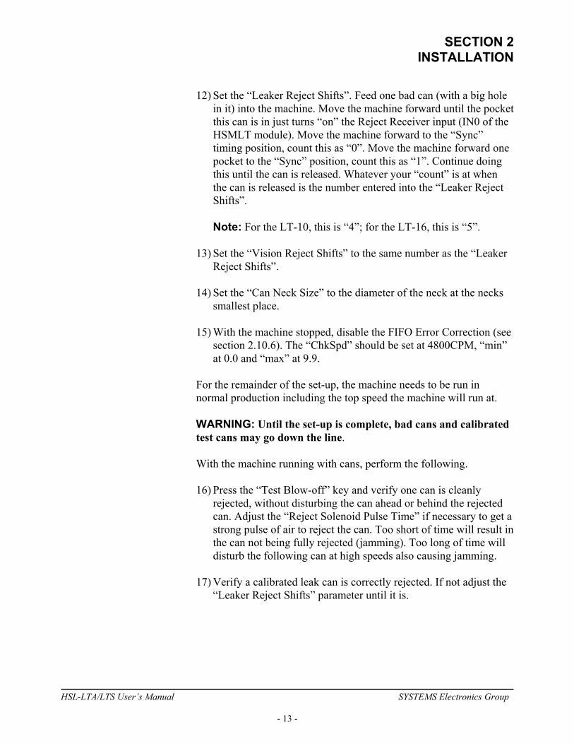
12) Set the “Leaker Reject Shifts”. Feed one bad can (with a big hole in it) into the machine. Move the machine forward until the pocket this can is in just turns “on” the Reject Receiver input (IN0 of the HSMLT module). Move the machine forward to the “Sync” timing position, count this as “0”. Move the machine forward one pocket to the “Sync” position, count this as “1”. Continue doing this until the can is released. Whatever your “count” is at when the can is released is the number entered into the “Leaker Reject Shifts”.
Note: For the LT-10, this is “4”; for the LT-16, this is “5”.
13) Set the “Vision Reject Shifts” to the same number as the “Leaker
Reject Shifts”. 14) Set the “Can Neck Size” to the diameter of the neck at the necks
smallest place. 15) With the machine stopped, disable the FIFO Error Correction (see
section 2.10.6). The “ChkSpd” should be set at 4800CPM, “min” at 0.0 and “max” at 9.9.
For the remainder of the set-up, the machine needs to be run in normal production including the top speed the machine will run at. WARNING: Until the set-up is complete, bad cans and calibrated test cans may go down the line. With the machine running with cans, perform the following. 16) Press the “Test Blow-off” key and verify one can is cleanly
rejected, without disturbing the can ahead or behind the rejected can. Adjust the “Reject Solenoid Pulse Time” if necessary to get a strong pulse of air to reject the can. Too short of time will result in the can not being fully rejected (jamming). Too long of time will disturb the following can at high speeds also causing jamming.
17) Verify a calibrated leak can is correctly rejected. If not adjust the
“Leaker Reject Shifts” parameter until it is.
HSL-LTA/LTS User’s Manual SYSTEMS Electronics Group
- 13 -
SECTION 2 INSTALLATION
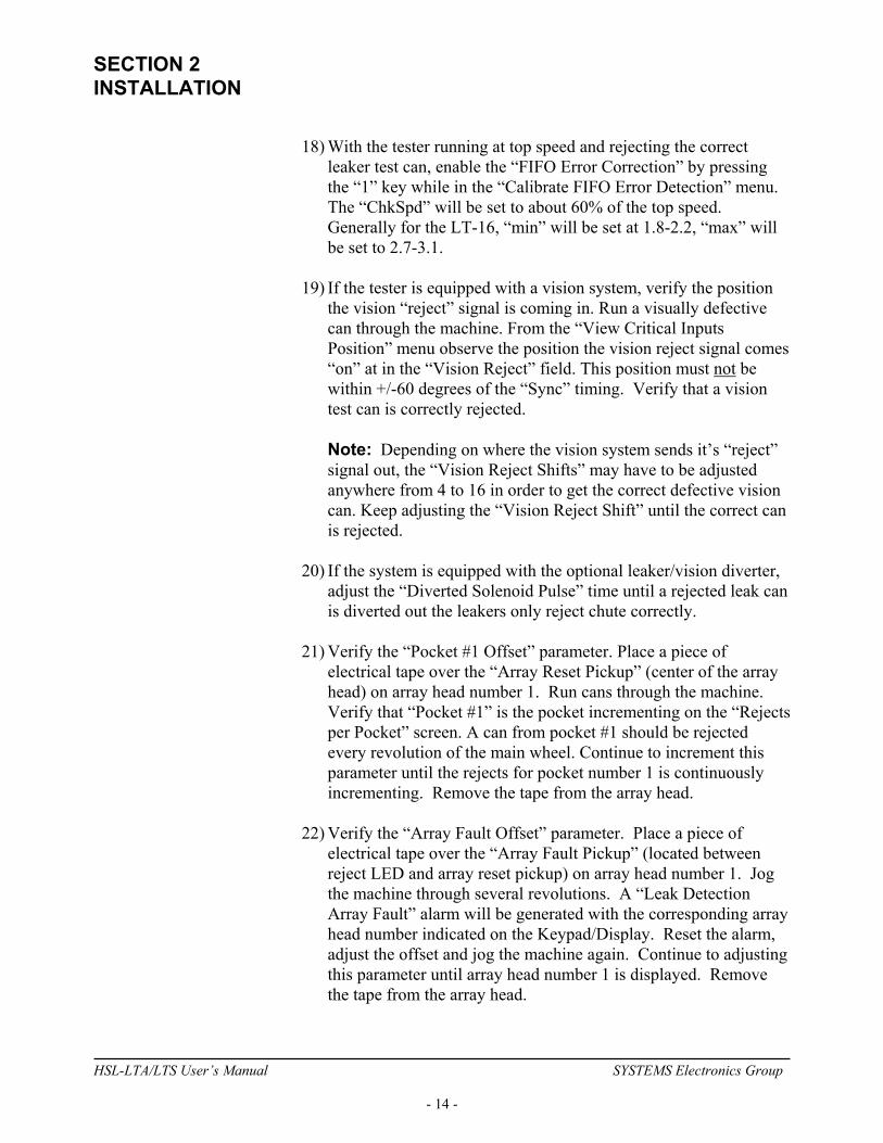
18) With the tester running at top speed and rejecting the correct leaker test can, enable the “FIFO Error Correction” by pressing the “1” key while in the “Calibrate FIFO Error Detection” menu. The “ChkSpd” will be set to about 60% of the top speed. Generally for the LT-16, “min” will be set at 1.8-2.2, “max” will be set to 2.7-3.1.
19) If the tester is equipped with a vision system, verify the position
the vision “reject” signal is coming in. Run a visually defective can through the machine. From the “View Critical Inputs Position” menu observe the position the vision reject signal comes “on” at in the “Vision Reject” field. This position must not be within +/-60 degrees of the “Sync” timing. Verify that a vision test can is correctly rejected.
Note: Depending on where the vision system sends it’s “reject” signal out, the “Vision Reject Shifts” may have to be adjusted anywhere from 4 to 16 in order to get the correct defective vision can. Keep adjusting the “Vision Reject Shift” until the correct can is rejected.
20) If the system is equipped with the optional leaker/vision diverter,
adjust the “Diverted Solenoid Pulse” time until a rejected leak can is diverted out the leakers only reject chute correctly.
21) Verify the “Pocket #1 Offset” parameter. Place a piece of
electrical tape over the “Array Reset Pickup” (center of the array head) on array head number 1. Run cans through the machine. Verify that “Pocket #1” is the pocket incrementing on the “Rejects per Pocket” screen. A can from pocket #1 should be rejected every revolution of the main wheel. Continue to increment this parameter until the rejects for pocket number 1 is continuously incrementing. Remove the tape from the array head.
22) Verify the “Array Fault Offset” parameter. Place a piece of
electrical tape over the “Array Fault Pickup” (located between reject LED and array reset pickup) on array head number 1. Jog the machine through several revolutions. A “Leak Detection Array Fault” alarm will be generated with the corresponding array head number indicated on the Keypad/Display. Reset the alarm, adjust the offset and jog the machine again. Continue to adjusting this parameter until array head number 1 is displayed. Remove the tape from the array head.
HSL-LTA/LTS User’s Manual SYSTEMS Electronics Group
- 14 -

SECTION 2 INSTALLATION
23) The set-up is now complete. If problems are in countered in any of the previous set-up steps, refer to the trouble-shooting section 6.2. Once all the parameters are set as required, save them to disk using the “HSMLT” set-up program (see section 5.8 –Upload (Save) Set-up Data).
________________________________________________________ 2.6 HSMLT SET-UP SOFTWARE INSTALLATION Follow the steps below to install the HSMLT Set-up software package and the HSMLT application programs onto the IBM PC or compatible, used to support the HSL-LTA/LTS package. The HSMLT set-up software is used to download the program to the HSMLT module, tune (set-up) the user adjustable variables of the HSL-LTA/LTS, download and upload (save) the user set-up variables to disk, and view rejects per pocket and shift data. ________________________________________________________ 2.6.1 WINDOWS INSTALLATION The Windows based HSMLT set-up program is compatible with Windows 95, 98, NT, ME, 2000 and XP. If the operating system of your computer is either an earlier version of Windows or DOS based, follow the steps described in section 2.6.2, DOS installation. To install the Windows based set-up program, run “setup.exe” located in the HSMLT subdirectory of the program disk. Follow the onscreen instructions to complete the process. If any problems are incurred during the installation process, try restarting your computer and running “setup.exe” again. Make sure all programs have been exited prior to installation.
HSL-LTA/LTS User’s Manual SYSTEMS Electronics Group
- 15 -
SECTION 2 INSTALLATION
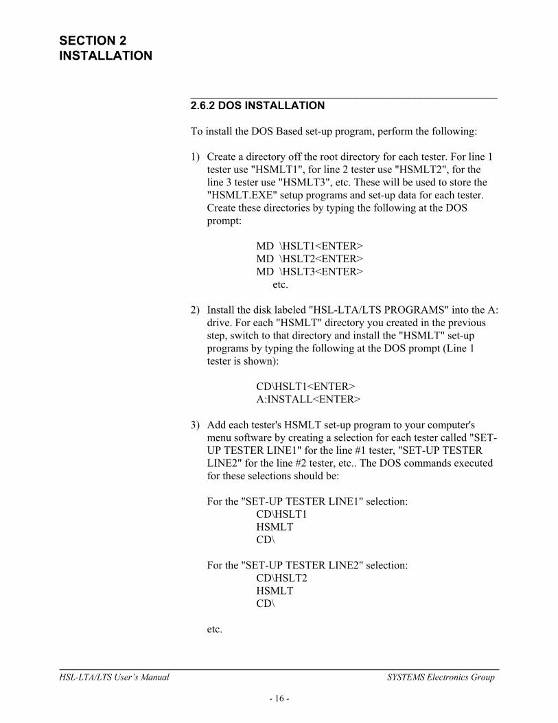
________________________________________________________ 2.6.2 DOS INSTALLATION To install the DOS Based set-up program, perform the following: 1) Create a directory off the root directory for each tester. For line 1
tester use "HSMLT1", for line 2 tester use "HSMLT2", for the line 3 tester use "HSMLT3", etc. These will be used to store the "HSMLT.EXE" setup programs and set-up data for each tester. Create these directories by typing the following at the DOS prompt:
MD \HSLT1<ENTER> MD \HSLT2<ENTER> MD \HSLT3<ENTER> etc. 2) Install the disk labeled "HSL-LTA/LTS PROGRAMS" into the A:
drive. For each "HSMLT" directory you created in the previous step, switch to that directory and install the "HSMLT" set-up programs by typing the following at the DOS prompt (Line 1 tester is shown):
CD\HSLT1<ENTER> A:INSTALL<ENTER> 3) Add each tester's HSMLT set-up program to your computer's
menu software by creating a selection for each tester called "SET-UP TESTER LINE1" for the line #1 tester, "SET-UP TESTER LINE2" for the line #2 tester, etc.. The DOS commands executed for these selections should be:
For the "SET-UP TESTER LINE1" selection: CD\HSLT1
HSMLT CD\ For the "SET-UP TESTER LINE2" selection: CD\HSLT2 HSMLT CD\ etc.
HSL-LTA/LTS User’s Manual SYSTEMS Electronics Group
- 16 -

SECTION 2 INSTALLATION
4) To execute the respective tester's set-up program, simply select the corresponding "SET-UP TESTER LINE" selection from the menu software's menu.
________________________________________________________ 2.7 SYSdev PROGRAM DEVELOPMENT SOFTWARE INSTALLATION The SYSdev Program Development software is an optional software package to perform on-line trouble-shooting and program modifications. If SYSdev was purchased with the HSL-LTA/LTS package and is not already installed on the your computer, install SYSdev onto the hard drive of your computer following the steps in section 1.5 of the SYSdev Program Development manual.
HSL-LTA/LTS User’s Manual SYSTEMS Electronics Group
- 17 -
SECTION 2 INSTALLATION
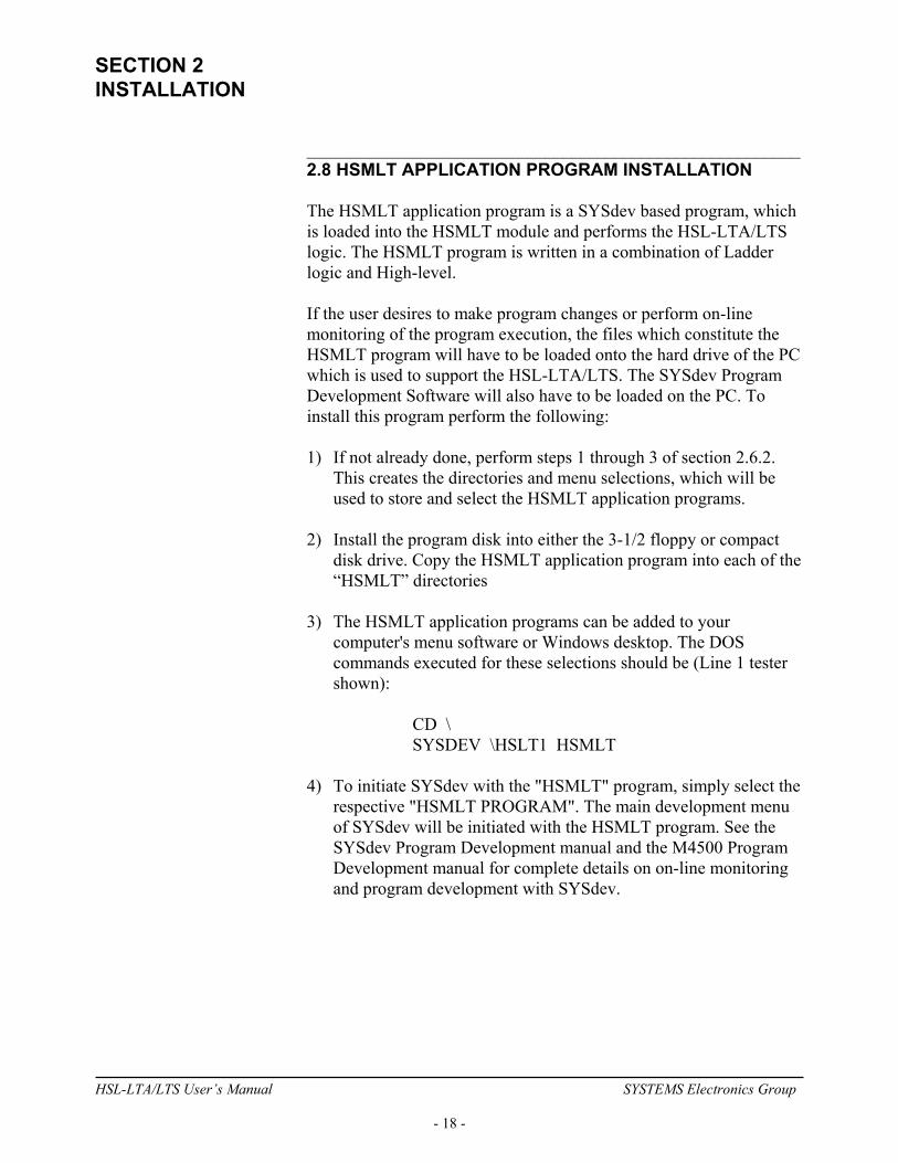
________________________________________________________ 2.8 HSMLT APPLICATION PROGRAM INSTALLATION The HSMLT application program is a SYSdev based program, which is loaded into the HSMLT module and performs the HSL-LTA/LTS logic. The HSMLT program is written in a combination of Ladder logic and High-level. If the user desires to make program changes or perform on-line monitoring of the program execution, the files which constitute the HSMLT program will have to be loaded onto the hard drive of the PC which is used to support the HSL-LTA/LTS. The SYSdev Program Development Software will also have to be loaded on the PC. To install this program perform the following: 1) If not already done, perform steps 1 through 3 of section 2.6.2.
This creates the directories and menu selections, which will be used to store and select the HSMLT application programs.
2) Install the program disk into either the 3-1/2 floppy or compact
disk drive. Copy the HSMLT application program into each of the “HSMLT” directories
3) The HSMLT application programs can be added to your
computer's menu software or Windows desktop. The DOS commands executed for these selections should be (Line 1 tester shown):
CD \ SYSDEV \HSLT1 HSMLT 4) To initiate SYSdev with the "HSMLT" program, simply select the
respective "HSMLT PROGRAM". The main development menu of SYSdev will be initiated with the HSMLT program. See the SYSdev Program Development manual and the M4500 Program Development manual for complete details on on-line monitoring and program development with SYSdev.
HSL-LTA/LTS User’s Manual SYSTEMS Electronics Group
- 18 -
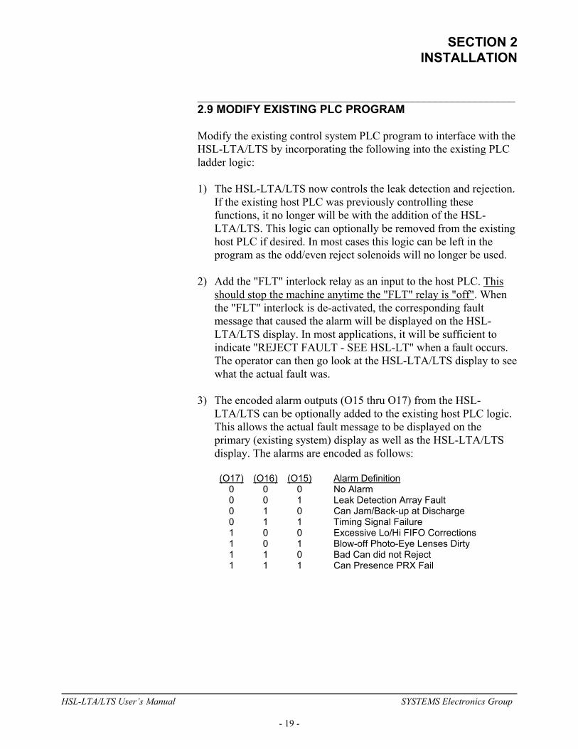
SECTION 2 INSTALLATION
________________________________________________________ 2.9 MODIFY EXISTING PLC PROGRAM Modify the existing control system PLC program to interface with the HSL-LTA/LTS by incorporating the following into the existing PLC ladder logic: 1) The HSL-LTA/LTS now controls the leak detection and rejection.
If the existing host PLC was previously controlling these functions, it no longer will be with the addition of the HSL-LTA/LTS. This logic can optionally be removed from the existing host PLC if desired. In most cases this logic can be left in the program as the odd/even reject solenoids will no longer be used.
2) Add the "FLT" interlock relay as an input to the host PLC. This
should stop the machine anytime the "FLT" relay is "off". When the "FLT" interlock is de-activated, the corresponding fault message that caused the alarm will be displayed on the HSL-LTA/LTS display. In most applications, it will be sufficient to indicate "REJECT FAULT - SEE HSL-LT" when a fault occurs. The operator can then go look at the HSL-LTA/LTS display to see what the actual fault was.
3) The encoded alarm outputs (O15 thru O17) from the HSL-
LTA/LTS can be optionally added to the existing host PLC logic. This allows the actual fault message to be displayed on the primary (existing system) display as well as the HSL-LTA/LTS display. The alarms are encoded as follows:
(O17) (O16) (O15) Alarm Definition 0 0 0 No Alarm 0 0 1 Leak Detection Array Fault 0 1 0 Can Jam/Back-up at Discharge 0 1 1 Timing Signal Failure 1 0 0 Excessive Lo/Hi FIFO Corrections 1 0 1 Blow-off Photo-Eye Lenses Dirty 1 1 0 Bad Can did not Reject 1 1 1 Can Presence PRX Fail
HSL-LTA/LTS User’s Manual SYSTEMS Electronics Group
- 19 -

SECTION 2 INSTALLATION
4) Add the "Good Can Count Pulse", "Leaker Reject Count Pulse", and "Vision Reject Count Pulse" outputs from the HSL-LTA/LTS to the existing host PLC if desired. The HSL-LTA/LTS accumulates all shift counts, but this allows the host PLC to accumulate the counts as well.
5) Add the "Machine Run" output to the PLC logic. This should be "
when the drive is enabled (running) and should be "off" when the drive is disabled (this includes auto stop conditions). This is true for jog modes as will.
6) Add the "Alarm Reset" output. This signal should be ”on" as long
as the system reset push-button is depressed.
HSL-LTA/LTS User’s Manual SYSTEMS Electronics Group
- 20 -
SECTION 2 INSTALLATION
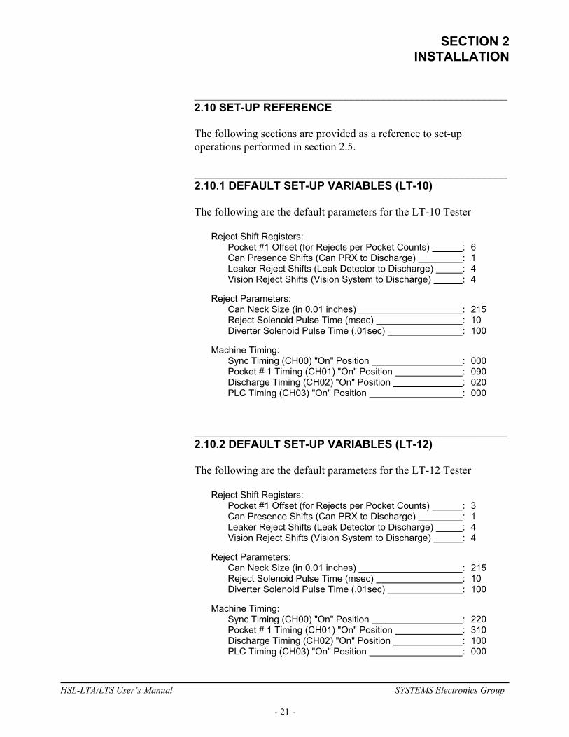
________________________________________________________ 2.10 SET-UP REFERENCE The following sections are provided as a reference to set-up operations performed in section 2.5. ________________________________________________________ 2.10.1 DEFAULT SET-UP VARIABLES (LT-10) The following are the default parameters for the LT-10 Tester Reject Shift Registers: Pocket #1 Offset (for Rejects per Pocket Counts) : 6 Can Presence Shifts (Can PRX to Discharge) : 1 Leaker Reject Shifts (Leak Detector to Discharge) : 4 Vision Reject Shifts (Vision System to Discharge) : 4 Reject Parameters: Can Neck Size (in 0.01 inches) : 215 Reject Solenoid Pulse Time (msec) : 10 Diverter Solenoid Pulse Time (.01sec) : 100 Machine Timing: Sync Timing (CH00) "On" Position : 000 Pocket # 1 Timing (CH01) "On" Position : 090 Discharge Timing (CH02) "On" Position : 020 PLC Timing (CH03) "On" Position : 000 ________________________________________________________ 2.10.2 DEFAULT SET-UP VARIABLES (LT-12) The following are the default parameters for the LT-12 Tester Reject Shift Registers: Pocket #1 Offset (for Rejects per Pocket Counts) : 3 Can Presence Shifts (Can PRX to Discharge) : 1 Leaker Reject Shifts (Leak Detector to Discharge) : 4 Vision Reject Shifts (Vision System to Discharge) : 4 Reject Parameters: Can Neck Size (in 0.01 inches) : 215 Reject Solenoid Pulse Time (msec) : 10 Diverter Solenoid Pulse Time (.01sec) : 100 Machine Timing: Sync Timing (CH00) "On" Position : 220 Pocket # 1 Timing (CH01) "On" Position : 310 Discharge Timing (CH02) "On" Position : 100 PLC Timing (CH03) "On" Position : 000
HSL-LTA/LTS User’s Manual SYSTEMS Electronics Group
- 21 -
SECTION 2 INSTALLATION
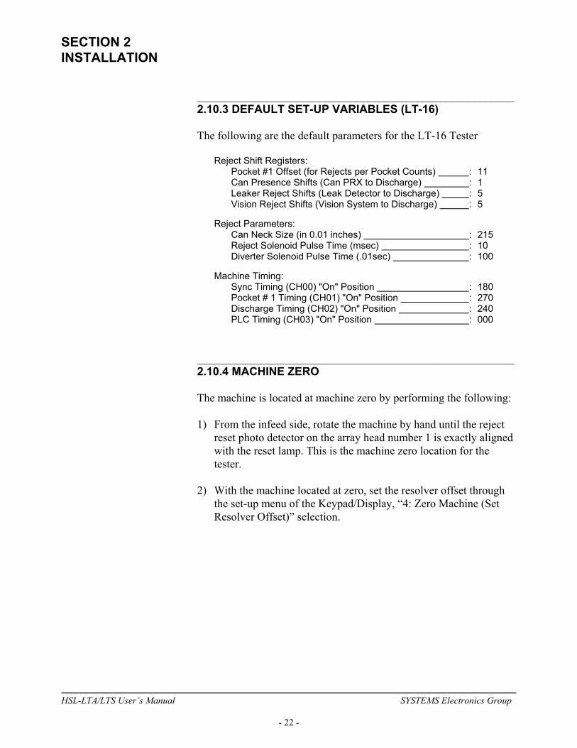
________________________________________________________ 2.10.3 DEFAULT SET-UP VARIABLES (LT-16) The following are the default parameters for the LT-16 Tester Reject Shift Registers: Pocket #1 Offset (for Rejects per Pocket Counts) : 11 Can Presence Shifts (Can PRX to Discharge) : 1 Leaker Reject Shifts (Leak Detector to Discharge) : 5 Vision Reject Shifts (Vision System to Discharge) : 5 Reject Parameters: Can Neck Size (in 0.01 inches) : 215 Reject Solenoid Pulse Time (msec) : 10 Diverter Solenoid Pulse Time (.01sec) : 100 Machine Timing: Sync Timing (CH00) "On" Position : 180 Pocket # 1 Timing (CH01) "On" Position : 270 Discharge Timing (CH02) "On" Position : 240 PLC Timing (CH03) "On" Position : 000 ________________________________________________________ 2.10.4 MACHINE ZERO The machine is located at machine zero by performing the following: 1) From the infeed side, rotate the machine by hand until the reject
reset photo detector on the array head number 1 is exactly aligned with the reset lamp. This is the machine zero location for the tester.
2) With the machine located at zero, set the resolver offset through
the set-up menu of the Keypad/Display, “4: Zero Machine (Set Resolver Offset)” selection.
HSL-LTA/LTS User’s Manual SYSTEMS Electronics Group
- 22 -

SECTION 2 INSTALLATION
________________________________________________________ 2.10.5 MACHINE TIMING SIGNALS Sync Timing (CH00): The Sync Timing is used to clock in the reject data from the Reject Array Receiver, Array Fault Receiver, and the vision system reject signal as well as clock the data from the Can Presence sensor. The Sync Timing should be as far as possible from the occurrence of the above four signals. For the LT-10, this is at 0 degrees, for the LT-16, the is at 180 degrees. Pocket #1 Timing (CH01): The Pocket #1 Timing is used to reset the pocket count to pocket #1. Set the Pocket #1 Timing 90 degrees following the Sync Timing. Discharge Timing (CH02): The Discharge Timing (CH02) should be set about 30 degrees before the location that the can is released from the tester. With cans in the machine, rotate the tester by hand to the location where the can is just released. Set the Discharge Timing (CH02) to the position 30 degrees before this can release position. PLC Timing (CH03): The PLC Timing is provided as an extra timing signal, which can be used by the existing host control system. Set this timing as desired. ________________________________________________________ 2.10.6 FIFO ERROR CORRECTION CALIBRATION The “FIFO Error Correction” is used to determine when a reject FIFO error has occurred and automatically correct the FIFO such that the correct bad cans are always rejected. An error is generally due to the “Can Presence Sensor” missing a can (side wall damage on the can), or when the “Reject Photo Eye” misses a can or double clocks (neck damage). The error correction logic verifies the reject FIFO is correct by comparing the average number of cans in the FIFO to a “calibrated” average number of cans that should be in the FIFO. The FIFO is “corrected” if the average falls below a “min” threshold or above a “max” threshold. The “5: Calibrate FIFO Error Detection” menu, accessed from the keypad/display on the HSL-LTA/LTS, is used to calibrate the error correction as well as observe the instantaneous number of cans in the FIFO, the average number of cans in the FIFO, the number of “Low” FIFO corrections, the number of “High” FIFO corrections, as well as the calibrated “Min/Max” threshold parameters.
HSL-LTA/LTS User’s Manual SYSTEMS Electronics Group
- 23 -

SECTION 2 INSTALLATION
The “Calibrate FIFO Error Detection” menu contains the following fields: CPM:xxxx CHK SPD:xxxx MIN:x.x Max:x.x FIFO:xx AVG:x.x LoCorr:xxx HiCorr:xxx The above fields are defined as follows: CPM: This is the current speed (Cans Per Minute) of the tester. CHK SPD: This is calculated automatically when the FIFO error
calibration is performed and is set to 60% of the speed of the tester when the calibration is performed. This is used to enable the error correction when the speed is greater than this value.
MIN: This is calculated automatically when the FIFO error
calibration is performed and is set to 83% of the average number of cans in the FIFO at calibration. If the average number of cans in the FIFO drops below this value when running within 60% of top speed, the FIFO is “corrected” up one can and the “LoCorr” count is incremented.
MAX: This is calculated automatically when the FIFO error
calibration is performed and is set to 117% of the average number of cans in the FIFO at calibration. If the average number of cans in the FIFO goes above this value when running within 60% of top speed, the FIFO is “corrected” down one can and the “HiCorr” count is incremented.
FIFO: This is the instantaneous number of cans in the FIFO. AVG: This is the average number of cans in the FIFO when the
machine is running above 800CPM (when the machine is running below 800, this is set to 0.0).
LoCorr: Low Correction: This is the number of times the “AVG”
dropped below “MIN” when running above 60% of top speed. A “low correction” is caused by either the “Can Presence” sensor missing a can or the Reject Photo Eye double clocking a can. “LoCorr” can be reset by pressing the “0” key while the “Calibrate FIFO Error Detection” menu is displayed.
HSL-LTA/LTS User’s Manual SYSTEMS Electronics Group
- 24 -
SECTION 2 INSTALLATION
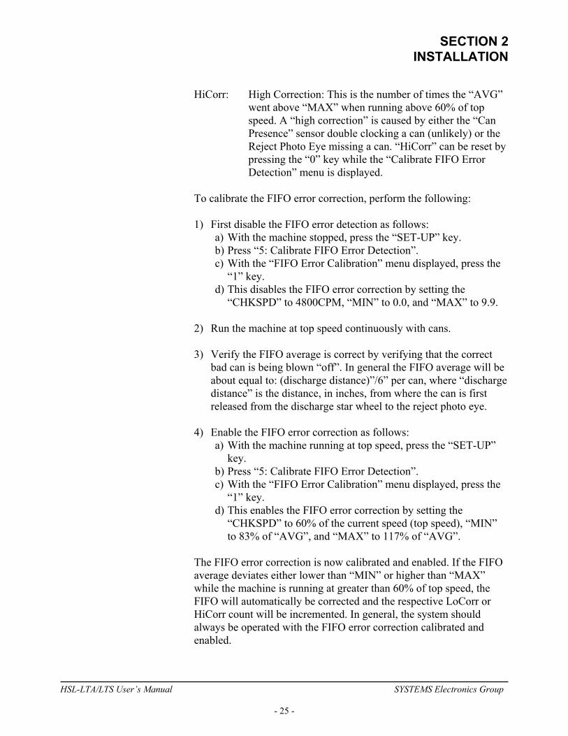
HiCorr: High Correction: This is the number of times the “AVG” went above “MAX” when running above 60% of top speed. A “high correction” is caused by either the “Can Presence” sensor double clocking a can (unlikely) or the Reject Photo Eye missing a can. “HiCorr” can be reset by pressing the “0” key while the “Calibrate FIFO Error Detection” menu is displayed.
To calibrate the FIFO error correction, perform the following: 1) First disable the FIFO error detection as follows:
a) With the machine stopped, press the “SET-UP” key. b) Press “5: Calibrate FIFO Error Detection”. c) With the “FIFO Error Calibration” menu displayed, press the
“1” key. d) This disables the FIFO error correction by setting the
“CHKSPD” to 4800CPM, “MIN” to 0.0, and “MAX” to 9.9.
2) Run the machine at top speed continuously with cans. 3) Verify the FIFO average is correct by verifying that the correct
bad can is being blown “off”. In general the FIFO average will be about equal to: (discharge distance)”/6” per can, where “discharge distance” is the distance, in inches, from where the can is first released from the discharge star wheel to the reject photo eye.
4) Enable the FIFO error correction as follows:
a) With the machine running at top speed, press the “SET-UP” key.
b) Press “5: Calibrate FIFO Error Detection”. c) With the “FIFO Error Calibration” menu displayed, press the
“1” key. d) This enables the FIFO error correction by setting the
“CHKSPD” to 60% of the current speed (top speed), “MIN” to 83% of “AVG”, and “MAX” to 117% of “AVG”.
The FIFO error correction is now calibrated and enabled. If the FIFO average deviates either lower than “MIN” or higher than “MAX” while the machine is running at greater than 60% of top speed, the FIFO will automatically be corrected and the respective LoCorr or HiCorr count will be incremented. In general, the system should always be operated with the FIFO error correction calibrated and enabled.
HSL-LTA/LTS User’s Manual SYSTEMS Electronics Group
- 25 -
SECTION 2 INSTALLATION
________________________________________________________ 2.10.7 VIEW CRITICAL INPUT POSITIONS MENU The “View Critical Input Positions” menu is used to view the position, in degrees, that the Reject Receiver, Array Fault Receiver, Can Presence Sensor, and Vision Reject signals are coming in at while the machine is running. Primarily this is to verify that none of these signals are coming in within +/-60 degrees of the “Sync” timing. If any of them do, the system could potentially miss clock the FIFO causing the wrong can to be intermittently rejected. The “6: View Critical Input Positions” menu is accessed from the main set-up menu when the “SET-UP” key has been depressed. ________________________________________________________ 2.11 HSMLT MODULE REPLACEMENT The following is provided only as a reference. These steps need only be performed in the event the HSMLT module needs to be replaced once installed. To replace the module, perform the following: 1) Turn both 115VAC and +24VDC power to the HSL-LTA/LTS
system "off" and remove the field wiring connectors from the HSMLT module.
2) Remove the 8-32 nuts and lock washers (7ea.) which retain the
module in the door and remove the module. 3) Remove the supplied field wiring connectors from the new
HSMLT module and install the new HSMLT module in the door cut-out from the front and re-install the 8-32 nuts and lock washers (7ea).
4) Install the existing pre-wired field wiring connectors on all the I/O
boards of the module (115VAC power connector, I/O slots0, 1, and 2, resolver connector, and IN0/IN1 connector). Make sure the field wiring connectors are fully mated in the module.
5) Apply 115VAC and +24VDC power to the HSL-LTA/LTS and
verify that the "PWR" and "RUN" LEDs on the HSMLT module are "on" and the "FLT" LED is "off".
HSL-LTA/LTS User’s Manual SYSTEMS Electronics Group
- 26 -

SECTION 2 INSTALLATION
6) Connect an RS-232 cable from the computer COM port to the "PROG" port on the HSMLT.
7) From the computer's menu program, select the respective tester's
"SET-UP TESTER" selection. The "HSMLT" set-up program will be invoked with the corresponding HSMLT application program for that tester.
8) Download the HSMLT application program to the module by
selecting "5: Download Program to Module" from the HSL-LT main menu. Press the <ENTER> key to start the download. Press any key to return back to the HSL-LT main menu.
9) Download the previously saved set-up data to the module by
selecting "6: Download Set-up data to Module" from the HSL-LT main menu. Press the <ENTER> key to start the download. Once the download is complete, press any key to return to the HSL-LT main menu. See section 5.7 for complete details.
10) The HSMLT is now ready to run, loaded with the HSMLT
program, and set-up data that was previously saved for the respective tester. Press <ESC> to return back to the computer's menu software program.
HSL-LTA/LTS User’s Manual SYSTEMS Electronics Group
- 27 -
SECTION 2 INSTALLATION
(This Page Intentionally Left Blank)
HSL-LTA/LTS User’s Manual SYSTEMS Electronics Group
- 28 -
SECTION 3 USING THE KEYPAD/DISPLAY
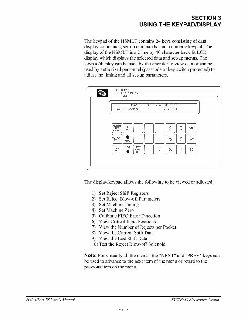
The keypad of the HSMLT contains 24 keys consisting of data display commands, set-up commands, and a numeric keypad. The display of the HSMLT is a 2 line by 40 character back-lit LCD display which displays the selected data and set-up menus. The keypad/display can be used by the operator to view data or can be used by authorized personnel (passcode or key switch protected) to adjust the timing and all set-up parameters.
The display/keypad allows the following to be viewed or adjusted:
1) Set Reject Shift Registers 2) Set Reject Blow-off Parameters 3) Set Machine Timing 4) Set Machine Zero 5) Calibrate FIFO Error Detection 6) View Critical Input Positions 7) View the Number of Rejects per Pocket 8) View the Current Shift Data 9) View the Last Shift Data 10) Test the Reject Blow-off Solenoid
Note: For virtually all the menus, the "NEXT" and "PREV" keys can be used to advance to the next item of the menu or retard to the previous item on the menu.
HSL-LTA/LTS User’s Manual SYSTEMS Electronics Group
- 29 -

SECTION 3 USING THE KEYPAD/DISPLAY
________________________________________________________ 3.1 DEFAULT SCREEN The default screen (displayed when no other commands are active) contains the following data:
MACHINE SPEED (CPM):xxxx GOOD CANS:xxxxxxx REJECTS:xxxxxx
Where the "Machine Speed" is the current speed of the tester, the "Good Cans" field is the total number of good cans tested so far into the current shift, and the "Rejects" field is the total number of leaker cans rejected from the machine (scrap) so far into the current shift. This display effectively replaces a speed meter, and two can counters. This screen is always returned to when no commands are active. ________________________________________________________ 3.2 "REJECTS PER POCKET" KEY The Number of Rejects per Pocket menu is provided to aid in the trouble-shooting of a light seal problem with a pocket or pockets. The total number of leaker rejects for each pocket since the last reset or end of shift is displayed. The operator can reset these counts at any time to aid in the trouble-shooting process. The data can be viewed simply be pressing this key. The display shows a series of screens each with four pockets from 1 through 10 as shown below:
-- DIAGNOSTICS (REJECTS PER POCKET) -- 1:xxxx 2:xxxx 3:xxxx 4:xxxx
Where the numbers 1 through 4 are the first 4 pockets and the "xxxx" would be the actual counts for the respective pockets. The user can advance to the next screen or retard to the previous screen by pressing the "NEXT" or "PREV" key respectively. The final screen prompts the user to reset the counts by pressing "0". If the counts are to be reset, press the "0" key, if not, press the "ESC" key. The default screen will now be displayed again. The "ESC" key can also be used at any time to abort the rejects per pocket data display and return back to the default screen. ________________________________________________________
HSL-LTA/LTS User’s Manual SYSTEMS Electronics Group
- 30 -

SECTION 3 USING THE KEYPAD/DISPLAY
3.3 "CURRENT SHIFT" KEY The "Current Shift" key is used to view the current shift data. This data is the totals so far into the shift. This data is transferred to the "Last shift" data when the end of shift input transfers from a "0" to a "1". This can be at the end of either an 8 or 12 hour shift or alternatively could be done at label changes such that the data collected would be for label runs rather than complete shifts. This data cannot be reset by the operator, only at the "end of shift" input transition. Note: The Current shift "Good Cans" and "Rejects" is displayed as part of the default screen. The Current Shift data is defined as follows: Good Cans: This is the total number of good cans tested so far into the shift. This is essentially a can counter. Rejects: This is the total number of leaker cans rejected from the machine so far into the shift. This also is essentially a can counter. Vision Inspection Rejects: This is the total number of cans rejected by the vision system (if used) so far into the shift. Rejects per Pocket (1:-16:): This is the total leaker rejects for each pocket. A disproportionately high count for a particular pocket indicates a light seal problem for that pocket. ________________________________________________________ 3.4 "LAST SHIFT" KEY The "Last Shift" data is identical to the current shift data except it is the totals for the previous 8 or 12 hour shift or previous label run, however the shift collection is set-up. This allows data collection and diagnostics to take place automatically over a two shift period.
HSL-LTA/LTS User’s Manual SYSTEMS Electronics Group
- 31 -
SECTION 3 USING THE KEYPAD/DISPLAY
________________________________________________________ 3.5 "SET-UP" KEY This selection is used to invoke the primary set-up menu. This consists of the following four selections: 1: SET REJECT SHIFT REGISTERS 2: SET REJECT BLOW-OFF PARAMETERS 3: SET MACHINE TIMING (SET-POINTS, ETC.) 4: ZERO MACHINE (SET RESOLVER OFFSET) 5: CALIBRATE FIFO ERROR DETECTION 6: VIEW CRITICAL INPUT POSITIONS When selected, each of the above selections brings up a sub-menu with the corresponding set-up parameters. To select the respective set-up sub-menu, simply press the corresponding numeric key (1 thru 6). The "NEXT" and "PREV" keys can be used to advance to the next or the previous variable respectively. To change a value, simply enter the new value on the numeric keypad and press <ENTER>. The value will be entered and the next variable will automatically be displayed. When the last variable is entered, the primary set-up menu is again displayed. Pressing <ESC> at anytime will also exit you back to the primary set-up menu. Note: The primary set-up menu is passcode protected. When the set-up key is first depressed, an "ENTER PASSCODE:" prompt is displayed. At this point, the 5-digit passcode must be entered followed by pressing the <ENTER> key. The primary set-up menu is then displayed and any of the parameters accessed by this menu may be changed. If the passcode entered is incorrect, the message "INCORRECT PASSCODE" will be displayed. At this time the passcode may be entered again or the <ESC> key can be pressed to return back to the main menu. When the passcode is entered, the digits entered are not displayed. Instead "*" characters are displayed as each digit is entered. This prevents unauthorized personnel from observing the passcode as it is entered. In addition, the "ENTER PASSCODE" prompt is only displayed for a maximum of 60 seconds. The correct passcode must be entered within this 60 second period otherwise the set-up mode is aborted and the main menu is re-displayed.
HSL-LTA/LTS User’s Manual SYSTEMS Electronics Group
- 32 -
SECTION 3 USING THE KEYPAD/DISPLAY
For user's that would prefer to use a keyed switch to prevent unauthorized access instead of a passcode, the "Set-Up Enable" input can be used. When this input is "on", the passcode prompt is bypassed and access to the primary set-up menu is provided immediately. If the "Set-Up Enable" input is "off", then the normal passcode prompt is displayed. A keyed switch can then be wired to the "Set-Up Enable" input such that when the switch is in the enable position, the input is "on". ________________________________________________________ 3.5.1 SET REJECT SHIFT REGISTERS This menu is activated when the "1" key (SET REJECT SHIFT REGISTERS) is pressed while the primary set-up menu is active. The following parameters may then be adjusted or viewed: Array Fault Offset (0-Number of Pockets): This number is used to correctly display the “Bad Array Head” number when a “Leak Detection Array Fault” occurs. This is adjusted such that an array fault on head number 1 is correctly displayed on the main screen when an array fault occurs on number 1. Pocket #1 Offset (0-Number of Pockets): This number is used to compensate for the number of pockets between the Reject Receiver and discharge location on the tester. This is adjusted such that a reject from pocket #1 is counted as a reject from pocket #1 in the “Rejects per Pocket” screen. This number is approximately = “Total Number of Pockets” – “Leaker Reject Shift” plus or minus one pocket. Can Presence Shifts (0-15): This is the number of pockets from the Can Presence Sensor to the tester discharge (pocket where cans are released from the machine). Leaker Reject Shifts (0-15): This is the number of pockets from the Reject Array Receiver pocket to the tester discharge (pocket where cans are released from the machine). Vision Reject Shifts (0-44): This is the number of pockets from the vision inspection system reject pocket to the tester discharge (pocket where cans are released from the machine, typically set to the same value as the leaker reject shifts shifts).
HSL-LTA/LTS User’s Manual SYSTEMS Electronics Group
- 33 -

SECTION 3 USING THE KEYPAD/DISPLAY
________________________________________________________ 3.5.2 SET REJECT BLOW-OFF PARAMETERS This menu is activated when the "2" key (SET REJECT BLOW-OFF PARAMETERS) is pressed while the primary set-up menu is active. The following blow-off set-up parameters may then be adjusted or viewed: Can Neck Size (in 0.01 inches): This parameter is used to calculate when to activate the reject blow-off as a function of the can speed. The can neck size is simply the diameter of the neck at it's most narrow point in 0.01 inches. For example, if the neck measures 2.15" at it's most narrow point, simply enter 215 for the can neck size. The valid range of this value is 180 to 350. The “Can Neck Size” parameter can be used to compensate for the response time of the blow-off solenoids. To advance the blow-off (activate solenoids earlier), make the “Can Neck Size” larger. To retard the blow-off (activate the solenoids later), make the “Can Neck Size” smaller. Reject Solenoid Pulse Time (msec): This is the number of milliseconds that the reject solenoids will be pulsed for when a bad can is rejected. This is adjusted to get a strong pulse of air to reject the can. Too short of time will result in the can not being fully rejected (jamming). Too long of time will disturb the following can at high speeds also causing jamming. Typically this is set from 10 to 12msec. The valid range for this parameter is 8 to 50msec. Diverter Solenoid Pulse Time (.01sec): This is the amount of time (in .01seconds) the leaker/vision diverter solenoid (if used) is pulsed for to divert a leaker reject down a separate leakers only reject chute. The valid range for this parameter is 0 to 250 (2.5seconds).
HSL-LTA/LTS User’s Manual SYSTEMS Electronics Group
- 34 -

SECTION 3 USING THE KEYPAD/DISPLAY
________________________________________________________ 3.5.3 SET MACHINE TIMING (SET-POINTS, ETC.) This menu is activated when the "3" key (SET MACHINE TIMING) is pressed while the primary set-up menu is active. The following timing set-up parameters may then be adjusted or viewed: Sync Timing (CH00): The Sync Timing is used to clock in the reject data from the Reject Array Receiver, Array Fault Receiver, and the vision system reject signal as well as clock the data from the Can Presence sensor. The Sync Timing should be as far as possible from the occurrence of the above four signals. For the LT-10, this is at 0 degrees, for the LT-16, the is at 180 degrees. Pocket #1 Timing (CH01): The Pocket #1 Timing is used to reset the pocket count to pocket #1. Set the Pocket #1 Timing 90 degrees following the Sync Timing. Discharge Timing (CH02): The Discharge Timing (CH02) should be set about 30 degrees before the location that the can is released from the tester. With cans in the machine, rotate the tester by hand to the location where the can is just released. Set the Discharge Timing (CH02) to the position 30 degrees before this can release position. PLC Timing (CH03): The PLC Timing is provided as an extra timing signal, which can be used by the existing host control system. Set this timing as desired. In addition to showing what the currently selected timing channel is set to, the display will also show the current angular position of the resolver. Note: 360 degrees is used for each pocket.
HSL-LTA/LTS User’s Manual SYSTEMS Electronics Group
- 35 -
SECTION 3 USING THE KEYPAD/DISPLAY
________________________________________________________ 3.5.4 ZERO MACHINE (SET RESOLVER OFFSET) This selection is used to auto zero the resolver. To set the machine zero (resolver offset) perform the following: 1) Position the machine at machine zero. From the infeed side, rotate
the machine by hand until the reject reset photo detector on the array head number 1 is exactly aligned with the reset lamp. This is the machine zero location for the tester.
2) Auto zero the resolver by selecting "4: ZERO MACHINE" from
the primary set-up menu. Enter "0" to zero the resolver. The timing set-up menu will be displayed, now showing the "POS:" at zero.
3) Exit back to the primary set-up menu by pressing <ESC>. Exit
back to the default screen by pressing <ESC> again. ________________________________________________________ 3.5.5 CALIBRATE FIFO ERROR DETECTION The “FIFO Error Correction” is used to determine when a reject FIFO error has occurred and automatically correct the FIFO such that the correct bad cans are always rejected. An error is generally due to the “Can Presence Sensor” missing a can (side wall damage on the can), or when the “Reject Photo Eye” misses a can or double clocks (neck damage). The error correction logic verifies the reject FIFO is correct by comparing the average number of cans in the FIFO to a “calibrated” average number of cans that should be in the FIFO. The FIFO is “corrected” if the average falls below a “min” threshold or above a “max” threshold See section 2.10.6 – FIFO Error Correction Calibration.
HSL-LTA/LTS User’s Manual SYSTEMS Electronics Group
- 36 -

SECTION 3 USING THE KEYPAD/DISPLAY
________________________________________________________ 3.5.6 VIEW CRITICAL INPUT POSITIONS The “View Critical Input Positions” menu is used to view the position, in degrees, that the Reject Receiver, Array Fault Receiver, Can Presence Sensor, and Vision Reject signals are coming in at while the machine is running. Primarily this is to verify that none of these signals are coming in within +/-60 degrees of the “Sync” timing. If any of them do, the system could potentially miss clock the FIFO causing the wrong can to be intermittently rejected. The “6: View Critical Input Positions” menu is accessed from the main set-up menu when the “SET-UP” key has been depressed. ________________________________________________________ 3.5.7 SET KEYPAD/DISPLAY "SET-UP" KEY PASSCODE The "Set Passcode" input to the HSL-LTA/LTS is used to actually set or view the passcode of the set-up menu. Normally this input should be "off". When the passcode is to be set, jumper this input to +24VDC (501) and press the "Set-Up" key. The "ENTER PASSCODE" prompt will be displayed and the current 5-digit passcode will be displayed with the prompt. This allows the passcode to be viewed if necessary. If the passcode is to be changed, enter any number between 0 and 64999 and press <ENTER>. Note: If passcode protection is not to be used, set the passcode to "0". Then when the passcode is prompted for after the "Set-up" key is pressed, simply press <ENTER> to proceed to the set-up menu. If the passcode protection is to be used, set the passcode to a number between 1 and 64999. Then when the "Set-up" key is pressed, the actual valid passcode number will have to be entered in order to gain access to the set-up menu. Once the passcode is set, turn the "Set Passcode" input back "off" and now the set-up menu will be passcode protected with the number you have entered as the passcode.
HSL-LTA/LTS User’s Manual SYSTEMS Electronics Group
- 37 -

SECTION 3 USING THE KEYPAD/DISPLAY
________________________________________________________ 3.6 "TEST BLOW-OFF" KEY This key is used to test the reject blow-off solenoid both while the machine is running with cans and with the machine stopped. Testing the blow-off with the machine running with cans verifies that the blow-off delay and pulse times are calculated correctly. When de-pressed, the next can detected by the reject photo-eye will be rejected. The solenoid is activated with the same delay and pulse times used when a leaker reject can is blown-off. With the machine stopped, de-pressing the "Test Blow-off" key will activate the reject blow-off immediately for the pulse time. This can be used to verify that the solenoid does indeed activate.
HSL-LTA/LTS User’s Manual SYSTEMS Electronics Group
- 38 -
SECTION 4 HSMLT WINDOWS BASED
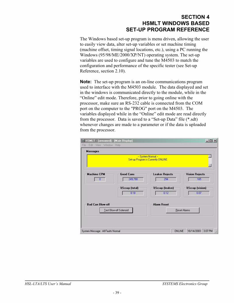
SET-UP PROGRAM REFERENCE The Windows based set-up program is menu driven, allowing the user to easily view data, alter set-up variables or set machine timing (machine offset, timing signal locations, etc.), using a PC running the Windows (95/98/ME/2000/XP/NT) operating system. The set-up variables are used to configure and tune the M4503 to match the configuration and performance of the specific tester (see Set-up Reference, section 2.10). Note: The set-up program is an on-line communications program used to interface with the M4503 module. The data displayed and set in the windows is communicated directly to the module, while in the “Online” edit mode. Therefore, prior to going online with the processor, make sure an RS-232 cable is connected from the COM port on the computer to the "PROG" port on the M4503. The variables displayed while in the “Online” edit mode are read directly from the processor. Data is saved to a “Set-up Data” file (*.sdt) whenever changes are made to a parameter or if the data is uploaded from the processor.
HSL-LTA/LTS User’s Manual SYSTEMS Electronics Group
- 39 -

SECTION 4 HSMLT WINDOWS BASED SET-UP PROGRAM REFERENCE
________________________________________________________ 4.1 GENERAL DESCRIPTION Title Bar: At the top of the window is the “Title Bar”. The title bar is used to display the name of the working “Set-up Data” file, as well as, the name of the active “Window”. The title bar is dark if the window is active and grayed if another window is active. The color depends on the settings of the Display Properties of the Control Panel. Status Bar: At the bottom of the window is the “Status Bar”. The status bar is used to display system messages, online or offline mode, as well as, the current time and date as set by the operating system. The system messages panel displays general information about operation of the system. The Online/Offline mode panel displays the status of the current set-up program mode of operation. The mode of operation can be changed by simply double clicking the online/offline mode panel. Hot Keys: Hot keys are activated by holding down the “ALT” key and simultaneously pressing the underlined letter of the desired function. Almost every function can be activated by either pressing a series of hot keys or using the “TAB” key to move between fields. Online/Offline Modes: The set-up program allows the user to make changes while “Online” with the processor. The “Offline” mode is used to preset parameters prior to download. All functions are available to the user while “Online”, however, specific “Online” functions are disabled in the “Offline” edit mode. Note: Offline changes can only be made by enabling “Offline Editing”, accessed under the “Edit” menu.
HSL-LTA/LTS User’s Manual SYSTEMS Electronics Group
- 40 -

SECTION 4 HSMLT WINDOWS BASED
SET-UP PROGRAM REFERENCE Getting Help: The entire contents of the user’s manual is contained within the help file. Pressing Ctrl+H will display the help file window.
Pressing the F1 key will display the contents file.
HSL-LTA/LTS User’s Manual SYSTEMS Electronics Group
- 41 -
SECTION 4 HSMLT WINDOWS BASED SET-UP PROGRAM REFERENCE
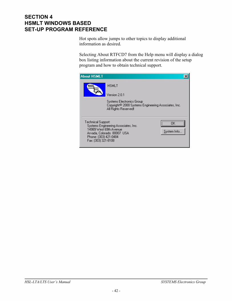
Hot spots allow jumps to other topics to display additional information as desired. Selecting About RTFCD7 from the Help menu will display a dialog box listing information about the current revision of the setup program and how to obtain technical support.
HSL-LTA/LTS User’s Manual SYSTEMS Electronics Group
- 42 -
SECTION 4 HSMLT WINDOWS BASED
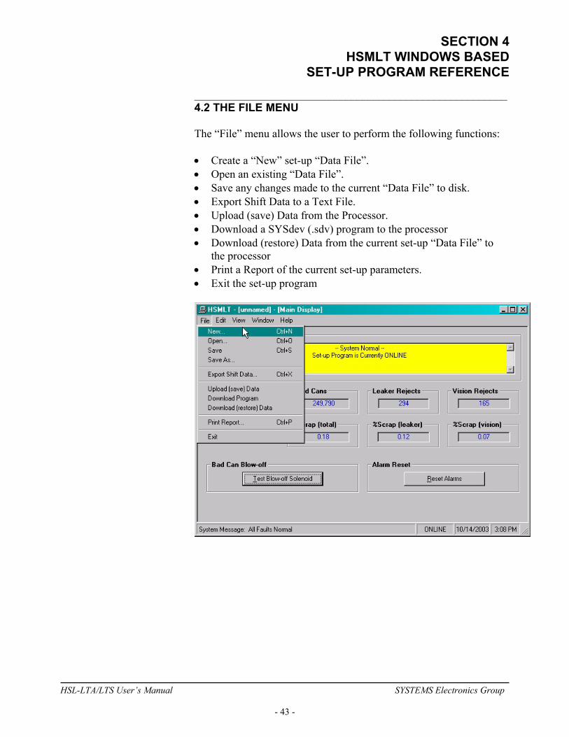
SET-UP PROGRAM REFERENCE ________________________________________________________ 4.2 THE FILE MENU The “File” menu allows the user to perform the following functions: • Create a “New” set-up “Data File”. • Open an existing “Data File”. • Save any changes made to the current “Data File” to disk. • Export Shift Data to a Text File. • Upload (save) Data from the Processor. • Download a SYSdev (.sdv) program to the processor • Download (restore) Data from the current set-up “Data File” to
the processor • Print a Report of the current set-up parameters. • Exit the set-up program
HSL-LTA/LTS User’s Manual SYSTEMS Electronics Group
- 43 -

SECTION 4 HSMLT WINDOWS BASED SET-UP PROGRAM REFERENCE
________________________________________________________ 4.2.1 THE SET-UP DATA FILE The set-up “Data File” (.sdt) is a binary access file, designed for fast file I/O operation. When the set-up program is first invoked, the default set-up parameters are loaded into memory. If changes are made to any of the set-up parameters (either online or offline), as well as shift data, the user will be flagged to “Save Changes” upon exit of the program. Note: Any windows based “Set-up” program can open a set-up “Data File”, however, the data tables will not be properly aligned. The user will be alerted to the problem if the set-up data file was created by a different set-up program or a different revision of the software. The set-up “Data File” is similar to that of a word processing file. When the program first starts a default file is loaded and the user is able to make any changes as desired. The set-up program is unaware of the settings and parameters that exist within the M4503. Therefore, to normalize the set-up program with the processor, the user should define or open an existing file, then upload “All” variables from the processor. This allows the user to either create a backup of the data or maintain an existing file. The user can even open a data file for another tester, save the file to a new name, make the necessary changes and simply download the new parameters to another processor. The following functions can be accessed any time, from any set-up or display windows. New: To create a “New” data file, select “New” from the “File” menu or press “Ctrl + N”. This creates a completely new file, loaded with the default variables and the word “[unnamed]” is displayed in the title bar. If any changes were made to the existing file, the user is prompted to save changes to the existing file. Open: To “Open” and existing data file, select “Open” from the “File” menu or press “Ctrl + O”. This displays a dialog box allowing the user to select an existing data file to open. The name of the file will be displayed in the title bar. If any changes were made to the existing file, the user will be prompted to save any changes before terminating the program.
HSL-LTA/LTS User’s Manual SYSTEMS Electronics Group
- 44 -
SECTION 4 HSMLT WINDOWS BASED
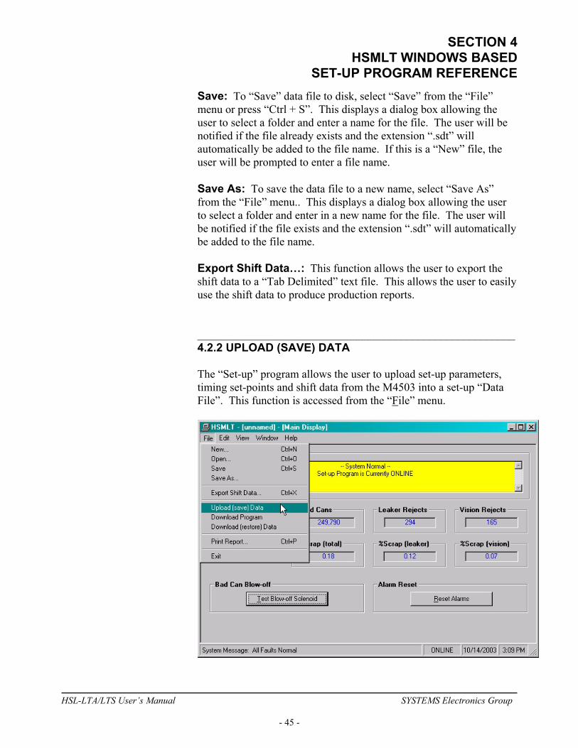
SET-UP PROGRAM REFERENCE Save: To “Save” data file to disk, select “Save” from the “File” menu or press “Ctrl + S”. This displays a dialog box allowing the user to select a folder and enter a name for the file. The user will be notified if the file already exists and the extension “.sdt” will automatically be added to the file name. If this is a “New” file, the user will be prompted to enter a file name. Save As: To save the data file to a new name, select “Save As” from the “File” menu.. This displays a dialog box allowing the user to select a folder and enter in a new name for the file. The user will be notified if the file exists and the extension “.sdt” will automatically be added to the file name. Export Shift Data…: This function allows the user to export the shift data to a “Tab Delimited” text file. This allows the user to easily use the shift data to produce production reports. ________________________________________________________ 4.2.2 UPLOAD (SAVE) DATA The “Set-up” program allows the user to upload set-up parameters, timing set-points and shift data from the M4503 into a set-up “Data File”. This function is accessed from the “File” menu.
HSL-LTA/LTS User’s Manual SYSTEMS Electronics Group
- 45 -

SECTION 4 HSMLT WINDOWS BASED SET-UP PROGRAM REFERENCE
________________________________________________________ 4.2.3 DOWNLOAD PROGRAM The “Set-up” program allows the user to “Download” any SYSdev program file to the M4503.
Note: To “Download” a SYSdev program to the processor, the program must be “Online”. If “Online” mode cannot be achieved, program download will not be executed. If the program is currently “Offline”, the user will be prompted to first go “Online”. Once selected, and the set-up program “Online” with the processor, a dialog box will be displayed, allowing the user to select the SYSdev file to download. Note: Only the files with the “.sdv” file extension will be displayed. It is important to keep in mind that only a valid M4500 PLC SYSdev file can be downloaded through the set-up program. Care should be taken when selecting a program to download.
HSL-LTA/LTS User’s Manual SYSTEMS Electronics Group
- 46 -

SECTION 4 HSMLT WINDOWS BASED
SET-UP PROGRAM REFERENCE Once selected, a message box is displayed informing the user of the current program, revision and checksum of the program loaded in the processor, as well as, that of the selected program. The user must confirm their selection by clicking the “Yes” command button.
After the user confirms their choice, program download is initiated and the current program download address is displayed. When program download is complete, the user is prompted to acknowledge. Control is passed back to the main program and the set-up program remains in an “Online” edit mode.
HSL-LTA/LTS User’s Manual SYSTEMS Electronics Group
- 47 -
SECTION 4 HSMLT WINDOWS BASED SET-UP PROGRAM REFERENCE
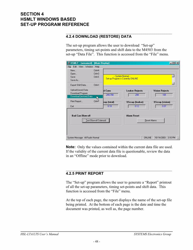
________________________________________________________ 4.2.4 DOWNLOAD (RESTORE) DATA The set-up program allows the user to download “Set-up” parameters, timing set-points and shift data to the M4503 from the set-up “Data File”. This function is accessed from the “File” menu.
Note: Only the values contained within the current data file are used. If the validity of the current data file is questionable, review the data in an “Offline” mode prior to download. ________________________________________________________ 4.2.5 PRINT REPORT The “Set-up” program allows the user to generate a “Report” printout of all the set-up parameters, timing set-points and shift data. This function is accessed from the “File” menu. At the top of each page, the report displays the name of the set-up file being printed. At the bottom of each page is the date and time the document was printed, as well as, the page number.
HSL-LTA/LTS User’s Manual SYSTEMS Electronics Group
- 48 -

SECTION 4 HSMLT WINDOWS BASED
SET-UP PROGRAM REFERENCE To printout a report of the settings contained in the set-up “Data File”, perform the following: 1) From the “File” menu, select “Print Report” or press “Ctrl + P”.
This displays the “Print Setup” dialog box, allowing the user to select a printer, as well as, the paper size and orientation. Once the user selects “OK”, the report is generated and sent to the specified printer device. This function makes use of the windows print manager, which allows the user to continue with their work while the document is being printed.
________________________________________________________ 4.3 THE EDIT MENU The “Edit” menu allows the user to perform the following functions: • Enable/Disable Offline Editing. • Set-up the Comm Port. • Set-Up Passcode
HSL-LTA/LTS User’s Manual SYSTEMS Electronics Group
- 49 -

SECTION 4 HSMLT WINDOWS BASED SET-UP PROGRAM REFERENCE
________________________________________________________ 4.3.1 ENABLE OFFLINE EDITING This function allows the user to perform “Offline” editing on the currently loaded set-up data file. This allows the user the ability to make any necessary changes to the set-up parameters while not online with the processor. If offline editing is not enabled, the user is only able to view the set-up parameters and shift data. When the program is first invoked, the default setting is offline editing disabled. The user will need to specifically select “Enable Offline Editing” from the edit menu (or press function key F2) to enable/disable this feature. ________________________________________________________ 4.3.2 SETUP COMM PORT This function allows the user to specify the serial communications port and rate to talk to the M4503. The programming port of the M4503 is set to 9600 baud.
Once selected, a dialog box requesting the user to select a “Comm Port” and “Baud Rate” will be displayed. The default setting is COM1 at 9600 baud. The option to select the 19200 baud rate is to allow the user to communicate with the processor via the S4516 serial communications board. In most cases the user will only need to specify the communications port and leave the baud rate at 9600. If communication problems occur, make sure there is a secure connection from the PC to the PLC. Then check the Comm port. In most cases the user will only need to select a new Comm port. If communication problems persist there may be another program causing a conflict with the port. Check the port configuration from the “Settings” folder.
HSL-LTA/LTS User’s Manual SYSTEMS Electronics Group
- 50 -
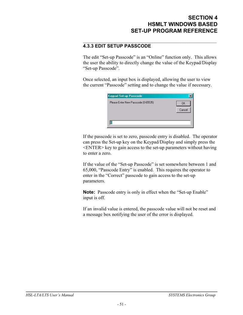
SECTION 4 HSMLT WINDOWS BASED
SET-UP PROGRAM REFERENCE ________________________________________________________ 4.3.3 EDIT SETUP PASSCODE The edit “Set-up Passcode” is an “Online” function only. This allows the user the ability to directly change the value of the Keypad/Display “Set-up Passcode”. Once selected, an input box is displayed, allowing the user to view the current “Passcode” setting and to change the value if necessary.
If the passcode is set to zero, passcode entry is disabled. The operator can press the Set-up key on the Keypad/Display and simply press the <ENTER> key to gain access to the set-up parameters without having to enter a zero. If the value of the “Set-up Passcode” is set somewhere between 1 and 65,000, “Passcode Entry” is enabled. This requires the operator to enter in the “Correct” passcode to gain access to the set-up parameters. Note: Passcode entry is only in effect when the “Set-up Enable” input is off. If an invalid value is entered, the passcode value will not be reset and a message box notifying the user of the error is displayed.
HSL-LTA/LTS User’s Manual SYSTEMS Electronics Group
- 51 -
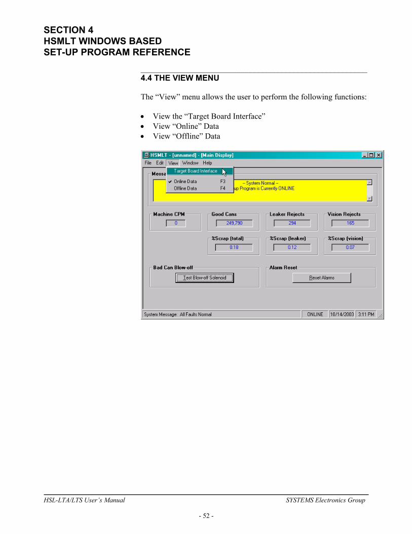
SECTION 4 HSMLT WINDOWS BASED SET-UP PROGRAM REFERENCE
________________________________________________________ 4.4 THE VIEW MENU The “View” menu allows the user to perform the following functions: • View the “Target Board Interface” • View “Online” Data • View “Offline” Data
HSL-LTA/LTS User’s Manual SYSTEMS Electronics Group
- 52 -
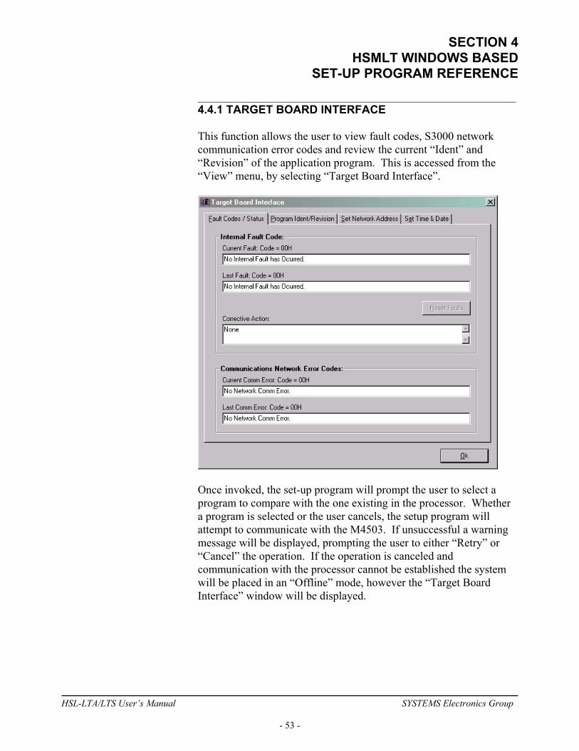
SECTION 4 HSMLT WINDOWS BASED
SET-UP PROGRAM REFERENCE ________________________________________________________ 4.4.1 TARGET BOARD INTERFACE This function allows the user to view fault codes, S3000 network communication error codes and review the current “Ident” and “Revision” of the application program. This is accessed from the “View” menu, by selecting “Target Board Interface”.
Once invoked, the set-up program will prompt the user to select a program to compare with the one existing in the processor. Whether a program is selected or the user cancels, the setup program will attempt to communicate with the M4503. If unsuccessful a warning message will be displayed, prompting the user to either “Retry” or “Cancel” the operation. If the operation is canceled and communication with the processor cannot be established the system will be placed in an “Offline” mode, however the “Target Board Interface” window will be displayed.
HSL-LTA/LTS User’s Manual SYSTEMS Electronics Group
- 53 -

SECTION 4 HSMLT WINDOWS BASED SET-UP PROGRAM REFERENCE
________________________________________________________ 4.4.2 VIEW ONLINE DATA This function allows the user to place the set-up program in an “Online” mode with the processor. This is accessed from the “View” menu, by selecting “Online Data” or by simply pressing the “F3” function key. Note: The program can be toggled between “Offline” and “Online” by simply double clicking on the “Online” or “Offline” panel displayed in the status bar at the bottom of the window. Once invoked, the set-up program will attempt to open the Comm port and communicate with the M4503. If the set-up program is unsuccessful, a warning message will be displayed prompting the user to either “Retry” or “Cancel” the operation. If the operation is canceled and communication with the processor cannot be established the system will be placed in an “Offline” edit mode. Note: Anytime while the set-up program is “Online” with the processor and communication is interrupted, a warning message will be displayed, prompting the user to either “Retry” or “Cancel” the operation. ________________________________________________________ 4.4.3 VIEW OFFLINE DATA This function allows the user to place the set-up program in an “Offline” mode. This is accessed by the “View” menu, by selecting “Offline Data” or by simply pressing the “F4” function key. This allows the user to perform “Offline” editing. All values displayed in “Offline” edit mode reflect the actual values contained in the currently loaded set-up data file. Note: The program can be toggled between “Online” and “Offline” by simply double clicking on the “Online” or “Offline” panel displayed in the status bar at the bottom of the window. Once invoked, the set-up program will close the Comm port and cease communication with the M4503.
HSL-LTA/LTS User’s Manual SYSTEMS Electronics Group
- 54 -
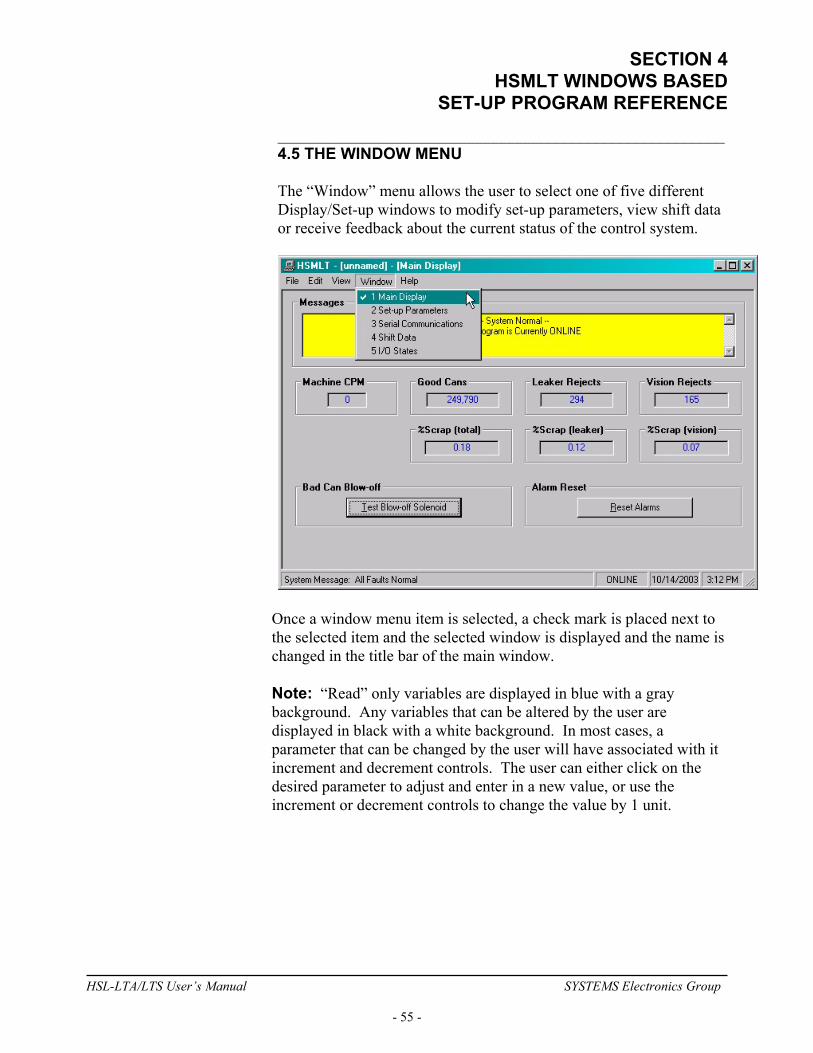
SECTION 4 HSMLT WINDOWS BASED
SET-UP PROGRAM REFERENCE ________________________________________________________ 4.5 THE WINDOW MENU The “Window” menu allows the user to select one of five different Display/Set-up windows to modify set-up parameters, view shift data or receive feedback about the current status of the control system.
Once a window menu item is selected, a check mark is placed next to the selected item and the selected window is displayed and the name is changed in the title bar of the main window. Note: “Read” only variables are displayed in blue with a gray background. Any variables that can be altered by the user are displayed in black with a white background. In most cases, a parameter that can be changed by the user will have associated with it increment and decrement controls. The user can either click on the desired parameter to adjust and enter in a new value, or use the increment or decrement controls to change the value by 1 unit.
HSL-LTA/LTS User’s Manual SYSTEMS Electronics Group
- 55 -
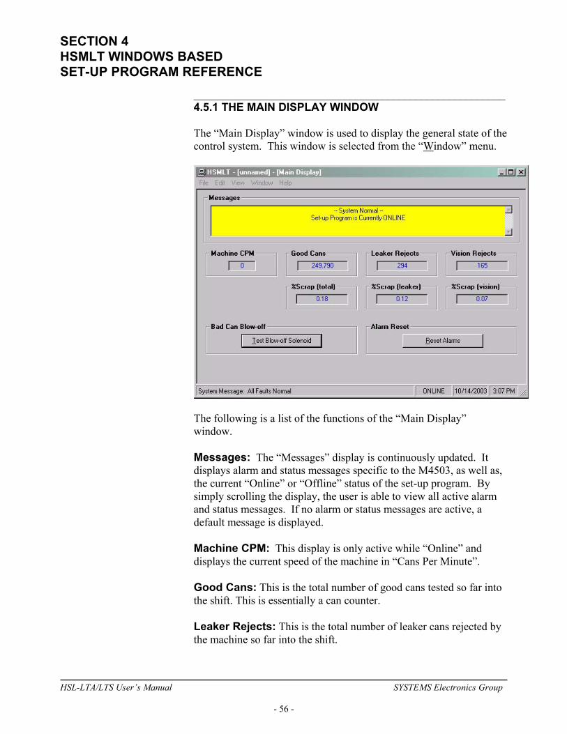
SECTION 4 HSMLT WINDOWS BASED SET-UP PROGRAM REFERENCE
________________________________________________________ 4.5.1 THE MAIN DISPLAY WINDOW The “Main Display” window is used to display the general state of the control system. This window is selected from the “Window” menu.
The following is a list of the functions of the “Main Display” window. Messages: The “Messages” display is continuously updated. It displays alarm and status messages specific to the M4503, as well as, the current “Online” or “Offline” status of the set-up program. By simply scrolling the display, the user is able to view all active alarm and status messages. If no alarm or status messages are active, a default message is displayed. Machine CPM: This display is only active while “Online” and displays the current speed of the machine in “Cans Per Minute”. Good Cans: This is the total number of good cans tested so far into the shift. This is essentially a can counter. Leaker Rejects: This is the total number of leaker cans rejected by the machine so far into the shift.
HSL-LTA/LTS User’s Manual SYSTEMS Electronics Group
- 56 -

SECTION 4 HSMLT WINDOWS BASED
SET-UP PROGRAM REFERENCE Vision Rejects: This is the total number of cans rejected by the vision inspection system (if used). %Scrap (total): This is the total percentage of cans tested that were blown off either due to a vision or leaker reject %Scrap (leaker): This is the total percentage of cans tested that were blown off due to a leaker reject signal. %Scrap (vision): This is the total percentage of cans tested that were blown off due to a vision reject signal. Note: If a can is both a vision reject and a leaker reject, it will only be counted as a leaker reject and not as both. ________________________________________________________ 4.5.2 THE SET-UP PARAMETERS WINDOW The “Set-up Parameters” window is used to view and adjust any of the set-up parameters. This window is selected from the “Window” menu.
This window utilizes a “TAB” control to divide the set-up parameters into three categories, similar to that of the Keypad/Display.
HSL-LTA/LTS User’s Manual SYSTEMS Electronics Group
- 57 -

SECTION 4 HSMLT WINDOWS BASED SET-UP PROGRAM REFERENCE
Reject Shift Registers: 1) Can Presence Shifts (0-44): This is the number of pockets
from the Can Presence Sensor to the tester discharge (pocket where cans are released from the machine).
2) Leaker Reject Shifts (0-44): This is the number of pockets
from the Reject Array Receiver pocket to the tester discharge (pocket where cans are released from the machine).
3) Vision Reject Shifts (0-44): This is the number of pockets
from the vision inspection system reject pocket to the tester discharge (pocket where cans are released from the machine).
4) Pocket #1 Offset (0-Number of Pockets): This number is
used to compensate for the number of pockets between the Reject Receiver and discharge location on the tester. This is adjusted such that a reject from pocket #1 is counted as a reject from pocket #1 in the “Rejects per Pocket” screen. This number is approximately = “Total Number of Pockets” – “Leaker Reject Shift” plus or minus one pocket.
5) Rejected Pocket: This is the number of the last pocket that
generated a vision reject. This is only available in the online mode.
6) Array Fault Offset (0-Number of Pockets): This number is
used to properly display a faulted array head when a Leak Detection Array Fault alarm occurs.
7) Faulted Array Head: This displays the faulted array head when
a Leak Detection Array Fault alarm occurs.
HSL-LTA/LTS User’s Manual SYSTEMS Electronics Group
- 58 -
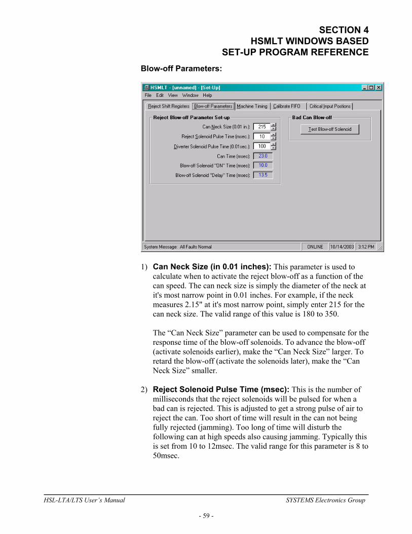
SECTION 4 HSMLT WINDOWS BASED
SET-UP PROGRAM REFERENCE Blow-off Parameters:
1) Can Neck Size (in 0.01 inches): This parameter is used to
calculate when to activate the reject blow-off as a function of the can speed. The can neck size is simply the diameter of the neck at it's most narrow point in 0.01 inches. For example, if the neck measures 2.15" at it's most narrow point, simply enter 215 for the can neck size. The valid range of this value is 180 to 350.
The “Can Neck Size” parameter can be used to compensate for the response time of the blow-off solenoids. To advance the blow-off (activate solenoids earlier), make the “Can Neck Size” larger. To retard the blow-off (activate the solenoids later), make the “Can Neck Size” smaller.
2) Reject Solenoid Pulse Time (msec): This is the number of
milliseconds that the reject solenoids will be pulsed for when a bad can is rejected. This is adjusted to get a strong pulse of air to reject the can. Too short of time will result in the can not being fully rejected (jamming). Too long of time will disturb the following can at high speeds also causing jamming. Typically this is set from 10 to 12msec. The valid range for this parameter is 8 to 50msec.
HSL-LTA/LTS User’s Manual SYSTEMS Electronics Group
- 59 -
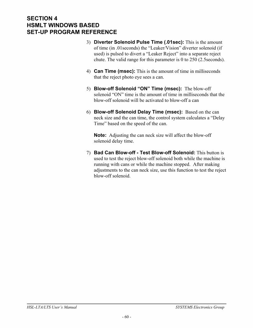
SECTION 4 HSMLT WINDOWS BASED SET-UP PROGRAM REFERENCE
3) Diverter Solenoid Pulse Time (.01sec): This is the amount of time (in .01seconds) the “Leaker/Vision” diverter solenoid (if used) is pulsed to divert a “Leaker Reject” into a separate reject chute. The valid range for this parameter is 0 to 250 (2.5seconds).
4) Can Time (msec): This is the amount of time in milliseconds
that the reject photo eye sees a can. 5) Blow-off Solenoid “ON” Time (msec): The blow-off
solenoid “ON” time is the amount of time in milliseconds that the blow-off solenoid will be activated to blow-off a can
6) Blow-off Solenoid Delay Time (msec): Based on the can
neck size and the can time, the control system calculates a “Delay Time” based on the speed of the can.
Note: Adjusting the can neck size will affect the blow-off solenoid delay time.
7) Bad Can Blow-off - Test Blow-off Solenoid: This button is
used to test the reject blow-off solenoid both while the machine is running with cans or while the machine stopped. After making adjustments to the can neck size, use this function to test the reject blow-off solenoid.
HSL-LTA/LTS User’s Manual SYSTEMS Electronics Group
- 60 -
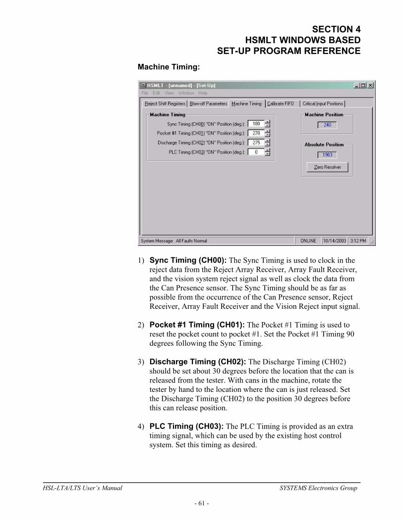
SECTION 4 HSMLT WINDOWS BASED
SET-UP PROGRAM REFERENCE Machine Timing:
1) Sync Timing (CH00): The Sync Timing is used to clock in the
reject data from the Reject Array Receiver, Array Fault Receiver, and the vision system reject signal as well as clock the data from the Can Presence sensor. The Sync Timing should be as far as possible from the occurrence of the Can Presence sensor, Reject Receiver, Array Fault Receiver and the Vision Reject input signal.
2) Pocket #1 Timing (CH01): The Pocket #1 Timing is used to
reset the pocket count to pocket #1. Set the Pocket #1 Timing 90 degrees following the Sync Timing.
3) Discharge Timing (CH02): The Discharge Timing (CH02)
should be set about 30 degrees before the location that the can is released from the tester. With cans in the machine, rotate the tester by hand to the location where the can is just released. Set the Discharge Timing (CH02) to the position 30 degrees before this can release position.
4) PLC Timing (CH03): The PLC Timing is provided as an extra
timing signal, which can be used by the existing host control system. Set this timing as desired.
HSL-LTA/LTS User’s Manual SYSTEMS Electronics Group
- 61 -

SECTION 4 HSMLT WINDOWS BASED SET-UP PROGRAM REFERENCE
5) Machine Position: This displays the position of the resolver, pocket to pocket (360 degrees per pocket).
6) Absolute Position: This displays the absolute position of the
resolver in counts for one full revolution of the discharge star-wheel.
7) Zero Resolver: Position the machine at machine zero. This is
the location where the pocket #1 reject reset photo detector is perfectly aligned with the reset lamp (see Machine Zero2.10.3).
Auto zero the resolver by clicking the “ZERO MACHINE" button. The position of the machine will now be displayed at zero
Note: The “Zero Resolver” button is only active in the online mode while the machine is at zero speed (no motion detected).
HSL-LTA/LTS User’s Manual SYSTEMS Electronics Group
- 62 -

SECTION 4 HSMLT WINDOWS BASED
SET-UP PROGRAM REFERENCE Calibrate FIFO: This is used to calibrate the can tracking error detection logic, as well as, observe the “Can Check Speed”, the instantaneous number of cans in the FIFO, average number of cans in the FIFO, the min and max error limits and the number of “Low” corrections, “High” corrections and missed can presence counts.
Can tracking error detection logic is used to determine when a reject FIFO error had occurred. This is generally due to the “Can Presence” sensor missing a can (side wall damage on the can) or when the “Reject Photo Eye” misses a can or double clocks a can (severe neck damage). The error detection logic verifies the reject FIFO is correct. This is done by comparing the average number of cans in the FIFO to a “calibrated” average. The error detection logic is calibrated by running the machine at top speed with a continuous flow of cans. By clicking on the “Calibrate FIFO” button, the error detection logic is calculated based on the speed of the machine. Note: Clicking the “Calibrate FIFO” button when the machine is stopped will disable the can tracking error detection logic.
HSL-LTA/LTS User’s Manual SYSTEMS Electronics Group
- 63 -
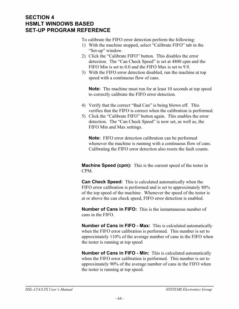
SECTION 4 HSMLT WINDOWS BASED SET-UP PROGRAM REFERENCE
To calibrate the FIFO error detection perform the following: 1) With the machine stopped, select “Calibrate FIFO” tab in the
“Set-up” window. 2) Click the “Calibrate FIFO” button. This disables the error
detection. The “Can Check Speed” is set at 4800 cpm and the FIFO Min is set to 0.0 and the FIFO Max is set to 9.9.
3) With the FIFO error detection disabled, run the machine at top speed with a continuous flow of cans.
Note: The machine must run for at least 10 seconds at top speed to correctly calibrate the FIFO error detection.
4) Verify that the correct “Bad Can” is being blown off. This
verifies that the FIFO is correct when the calibration is performed. 5) Click the “Calibrate FIFO” button again. This enables the error
detection. The “Can Check Speed” is now set, as well as, the FIFO Min and Max settings.
Note: FIFO error detection calibration can be performed whenever the machine is running with a continuous flow of cans. Calibrating the FIFO error detection also resets the fault counts.
Machine Speed (cpm): This is the current speed of the tester in CPM. Can Check Speed: This is calculated automatically when the FIFO error calibration is performed and is set to approximately 80% of the top speed of the machine. Whenever the speed of the tester is at or above the can check speed, FIFO error detection is enabled. Number of Cans in FIFO: This is the instantaneous number of cans in the FIFO. Number of Cans in FIFO - Max: This is calculated automatically when the FIFO error calibration is performed. This number is set to approximately 110% of the average number of cans in the FIFO when the tester is running at top speed Number of Cans in FIFO - Min: This is calculated automatically when the FIFO error calibration is performed. This number is set to approximately 90% of the average number of cans in the FIFO when the tester is running at top speed.
HSL-LTA/LTS User’s Manual SYSTEMS Electronics Group
- 64 -
SECTION 4 HSMLT WINDOWS BASED
SET-UP PROGRAM REFERENCE Number of Cans in FIFO - Avg.: This is the average number of cans in the FIFO when the machine is running above 800 cpm FIFO Low Corrections Count: This is the number of FIFO faults that have occurred when the average number of cans in the FIFO has dropped below the FIFO Min. A FIFO low fault would be caused by double clocking a can at the “Reject Photo Eye”. This count is retained indefinitely but can be reset by clicking the “Calibrate FIFO” button. FIFO High Corrections Count: This is the number of FIFO faults that have occurred when the average number of cans in the FIFO has exceeded the MIFO Max. A FIFO high fault would be caused by missing a can at the “Reject Photo Eye”. This count is retained indefinitely but can be reset by clicking the “Calibrate FIFO” button. Missed Can Presence Count: This is the number of FIFO faults that have occurred due to missing a can at the “Can Presence” sensor. This count is retained indefinitely but can be reset by clicking the “Calibrate FIFO” button.
HSL-LTA/LTS User’s Manual SYSTEMS Electronics Group
- 65 -
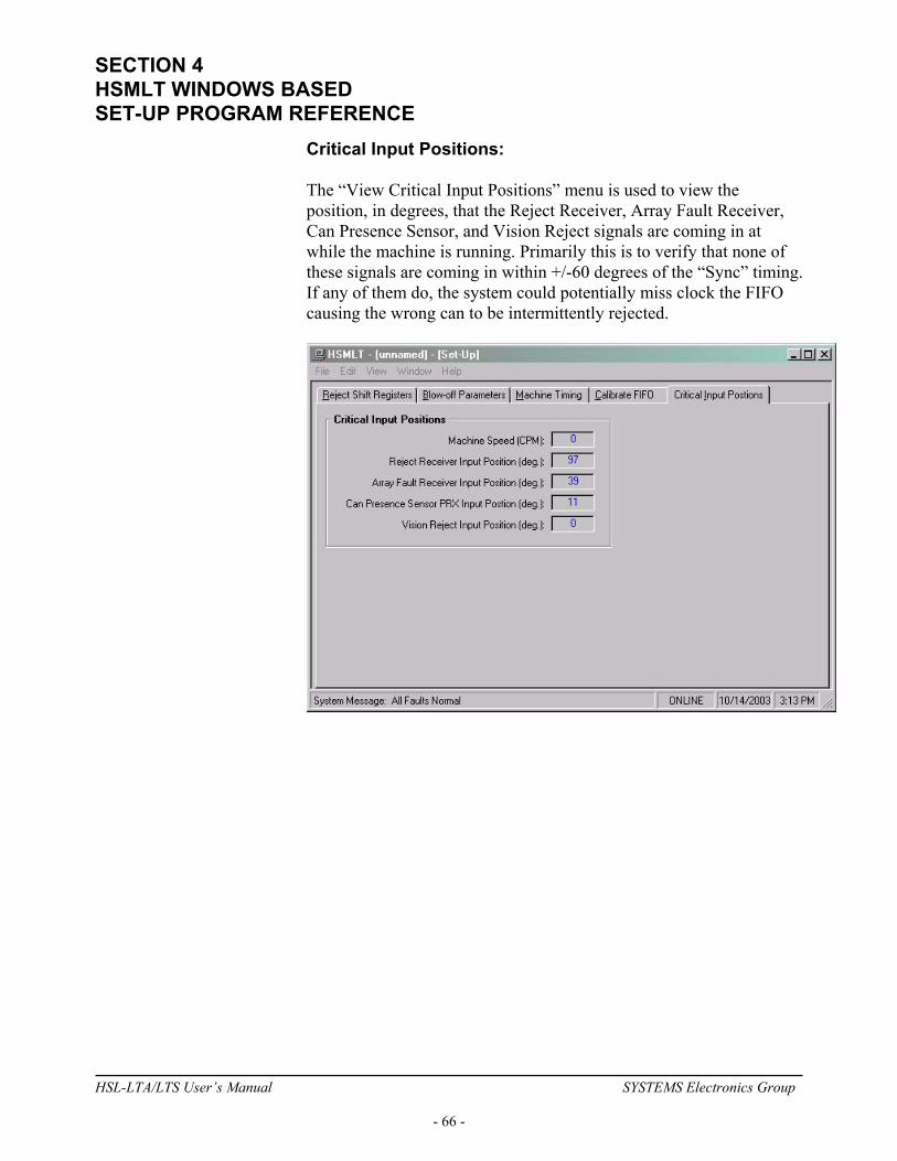
SECTION 4 HSMLT WINDOWS BASED SET-UP PROGRAM REFERENCE
Critical Input Positions: The “View Critical Input Positions” menu is used to view the position, in degrees, that the Reject Receiver, Array Fault Receiver, Can Presence Sensor, and Vision Reject signals are coming in at while the machine is running. Primarily this is to verify that none of these signals are coming in within +/-60 degrees of the “Sync” timing. If any of them do, the system could potentially miss clock the FIFO causing the wrong can to be intermittently rejected.
HSL-LTA/LTS User’s Manual SYSTEMS Electronics Group
- 66 -
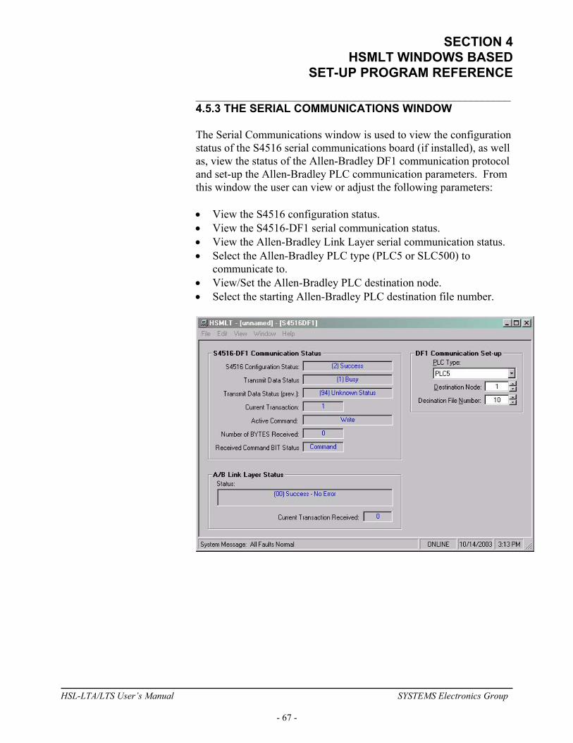
SECTION 4 HSMLT WINDOWS BASED
SET-UP PROGRAM REFERENCE ________________________________________________________ 4.5.3 THE SERIAL COMMUNICATIONS WINDOW The Serial Communications window is used to view the configuration status of the S4516 serial communications board (if installed), as well as, view the status of the Allen-Bradley DF1 communication protocol and set-up the Allen-Bradley PLC communication parameters. From this window the user can view or adjust the following parameters: • View the S4516 configuration status. • View the S4516-DF1 serial communication status. • View the Allen-Bradley Link Layer serial communication status. • Select the Allen-Bradley PLC type (PLC5 or SLC500) to
communicate to. • View/Set the Allen-Bradley PLC destination node. • Select the starting Allen-Bradley PLC destination file number.
HSL-LTA/LTS User’s Manual SYSTEMS Electronics Group
- 67 -
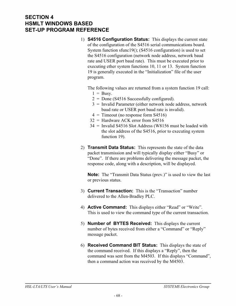
SECTION 4 HSMLT WINDOWS BASED SET-UP PROGRAM REFERENCE
1) S4516 Configuration Status: This displays the current state of the configuration of the S4516 serial communications board. System function sfunc19(); (S4516 configuration) is used to set the S4516 configuration (network node address, network baud rate and USER port baud rate). This must be executed prior to executing ether system functions 10, 11 or 13. System function 19 is generally executed in the “Initialization” file of the user program.
The following values are returned from a system function 19 call: 1 = Busy. 2 = Done (S4516 Successfully configured). 3 = Invalid Parameter (either network node address, network
baud rate or USER port baud rate is invalid). 4 = Timeout (no response form S4516) 32 = Hardware ACK error from S4516 34 = Invalid S4516 Slot Address (W8156 must be loaded with
the slot address of the S4516, prior to executing system function 19).
2) Transmit Data Status: This represents the state of the data
packet transmission and will typically display either “Busy” or “Done”. If there are problems delivering the message packet, the response code, along with a description, will be displayed.
Note: The “Transmit Data Status (prev.)” is used to view the last or previous status.
3) Current Transaction: This is the “Transaction” number
delivered to the Allen-Bradley PLC. 4) Active Command: This displays either “Read” or “Write”.
This is used to view the command type of the current transaction. 5) Number of BYTES Received: This displays the current
number of bytes received from either a “Command” or “Reply” message packet.
6) Received Command BIT Status: This displays the state of
the command received. If this displays a “Reply”, then the command was sent from the M4503. If this displays “Command”, then a command action was received by the M4503.
HSL-LTA/LTS User’s Manual SYSTEMS Electronics Group
- 68 -

SECTION 4 HSMLT WINDOWS BASED
SET-UP PROGRAM REFERENCE 7) A/B Link Layer Status: This displays the status of the receipt
of the message packet sent to the Allen-Bradley PLC. If the delivery is not successful, an error code along with a description is displayed. Refer the to the Allen-Bradley Communication Protocol and Command Set reference manual for more information on “Link Layer” error codes.
8) A/B Link Layer – Current Transaction Received: This is
the “Transaction” number received from the Allen-Bradley PLC. 9) PLC Type: This is used to specify the “Type” of PLC the
M4503 will communicate to. The user can choose from “PLC5” or “SLC500”.
Note: This parameter should be set prior to communicating with an A/B processor.
10) Destination Node: This is used to set the node number of the
A/B PLC to send and receive data from. This also displays the node number of the A/B PLC that send a “Command” message packet.
11) Destination File Number: This is the file number the M4503
will read and write data from. See Appendix B for a description of the data read from and written to an Allen-Bradley PLC.
HSL-LTA/LTS User’s Manual SYSTEMS Electronics Group
- 69 -

SECTION 4 HSMLT WINDOWS BASED SET-UP PROGRAM REFERENCE
________________________________________________________ 4.5.4 THE SHIFT DATA WINDOW The “Shift Data” window is used to view the shift data collected by the M4503. This window is selected from the “Window” menu.
This window utilizes a “TAB” control to divide the set-up parameters into three categories, similar to that of the Keypad/Display. These sections are as follows: Rejects Per Pocket: The number of leaker rejects per pocket menu is provided to aid in the trouble-shooting of a light seal problem with a pocket or pockets. The total number of rejects for each pocket since the last reset or end of shift is displayed. Note: Prior to selecting this selection, make sure the RS-232 cable is connected from the COM port on the computer to the "PROG" port of the M4503. 1) Rejected Pocket: This is the number of the last pocket that
generated a vision reject. This is only available in the online mode.
HSL-LTA/LTS User’s Manual SYSTEMS Electronics Group
- 70 -
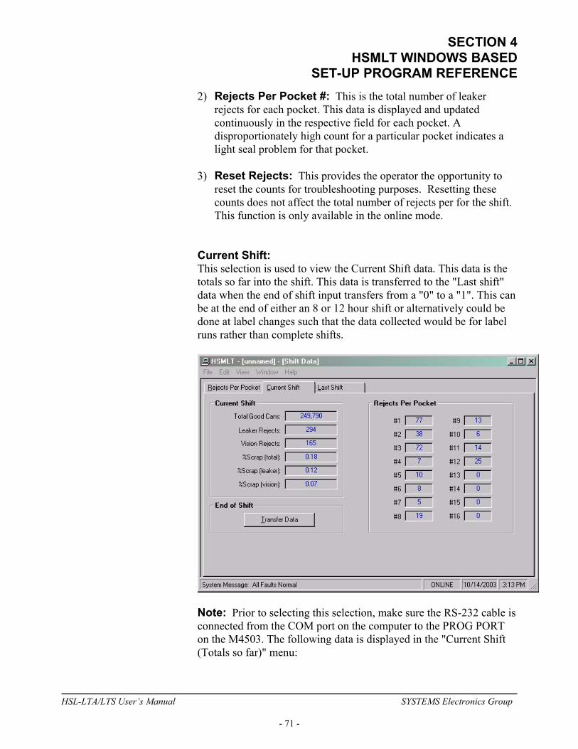
SECTION 4 HSMLT WINDOWS BASED
SET-UP PROGRAM REFERENCE 2) Rejects Per Pocket #: This is the total number of leaker
rejects for each pocket. This data is displayed and updated continuously in the respective field for each pocket. A disproportionately high count for a particular pocket indicates a light seal problem for that pocket.
3) Reset Rejects: This provides the operator the opportunity to
reset the counts for troubleshooting purposes. Resetting these counts does not affect the total number of rejects per for the shift. This function is only available in the online mode.
Current Shift: This selection is used to view the Current Shift data. This data is the totals so far into the shift. This data is transferred to the "Last shift" data when the end of shift input transfers from a "0" to a "1". This can be at the end of either an 8 or 12 hour shift or alternatively could be done at label changes such that the data collected would be for label runs rather than complete shifts.
Note: Prior to selecting this selection, make sure the RS-232 cable is connected from the COM port on the computer to the PROG PORT on the M4503. The following data is displayed in the "Current Shift (Totals so far)" menu:
HSL-LTA/LTS User’s Manual SYSTEMS Electronics Group
- 71 -
SECTION 4 HSMLT WINDOWS BASED SET-UP PROGRAM REFERENCE
1) End of Shift - Transfer Data: This button is used to invoke an end of shift data transfer. This will cause the current shift data to be transferred to the last shift and then all counts reset to zero.
2) Total Good Cans Tested: This is the total number of good
cans tested so far into the shift. This is essentially a can counter. 3) Total Leaker Rejects: This is the total number of leaker cans
rejected by the machine so far into the shift. 4) Total Vision Inspection Rejects: This is the total number of
cans rejected by the vision inspection system (if used). 5) %Scrap (total): This is the total percentage of cans tested that
were blown off either due to a vision or leaker reject 6) %Scrap (leaker): This is the total percentage of cans tested that
were blown off due to a leaker reject signal. 7) %Scrap (vision): This is the total percentage of cans tested that
were blown off due to a vision reject signal.
Note: If a can is both a vision reject and a leaker reject, it will only be counted as a leaker reject and not as both.
8) Rejects Per Pocket: This is the total leaker rejects for each
pocket. A disproportionately high count for a particular pocket indicates a light seal problem for that pocket.
HSL-LTA/LTS User’s Manual SYSTEMS Electronics Group
- 72 -

SECTION 4 HSMLT WINDOWS BASED
SET-UP PROGRAM REFERENCE Last Shift: The "Last Shift" data is identical to the current shift data except it is the totals for the previous 8 or 12 hour shift or previous label run, how ever the shift collection is set-up. This allows data collection and diagnostics to take place automatically over a two shift period. Refer to the previous section for definitions of the data fields in the "Last Shift" data menu.
HSL-LTA/LTS User’s Manual SYSTEMS Electronics Group
- 73 -

SECTION 4 HSMLT WINDOWS BASED SET-UP PROGRAM REFERENCE
________________________________________________________ 4.5.5 THE I/O STATES WINDOW The “I/O States” window is provided to display states of the inputs and outputs. The control boards, the states of the timing channels, as well as states of the M4503 are shown. This includes the interrupt inputs (IN0 and IN1), the analog I/O and the resolver. These values are displayed as read by the M4503 processor
HSL-LTA/LTS User’s Manual SYSTEMS Electronics Group
- 74 -
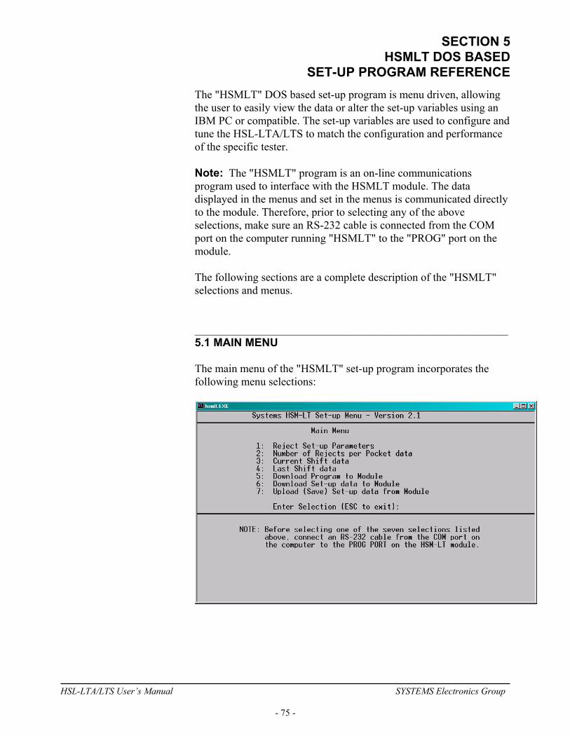
SECTION 5 HSMLT DOS BASED
SET-UP PROGRAM REFERENCE The "HSMLT" DOS based set-up program is menu driven, allowing the user to easily view the data or alter the set-up variables using an IBM PC or compatible. The set-up variables are used to configure and tune the HSL-LTA/LTS to match the configuration and performance of the specific tester. Note: The "HSMLT" program is an on-line communications program used to interface with the HSMLT module. The data displayed in the menus and set in the menus is communicated directly to the module. Therefore, prior to selecting any of the above selections, make sure an RS-232 cable is connected from the COM port on the computer running "HSMLT" to the "PROG" port on the module. The following sections are a complete description of the "HSMLT" selections and menus. ________________________________________________________ 5.1 MAIN MENU The main menu of the "HSMLT" set-up program incorporates the following menu selections:
HSL-LTA/LTS User’s Manual SYSTEMS Electronics Group
- 75 -
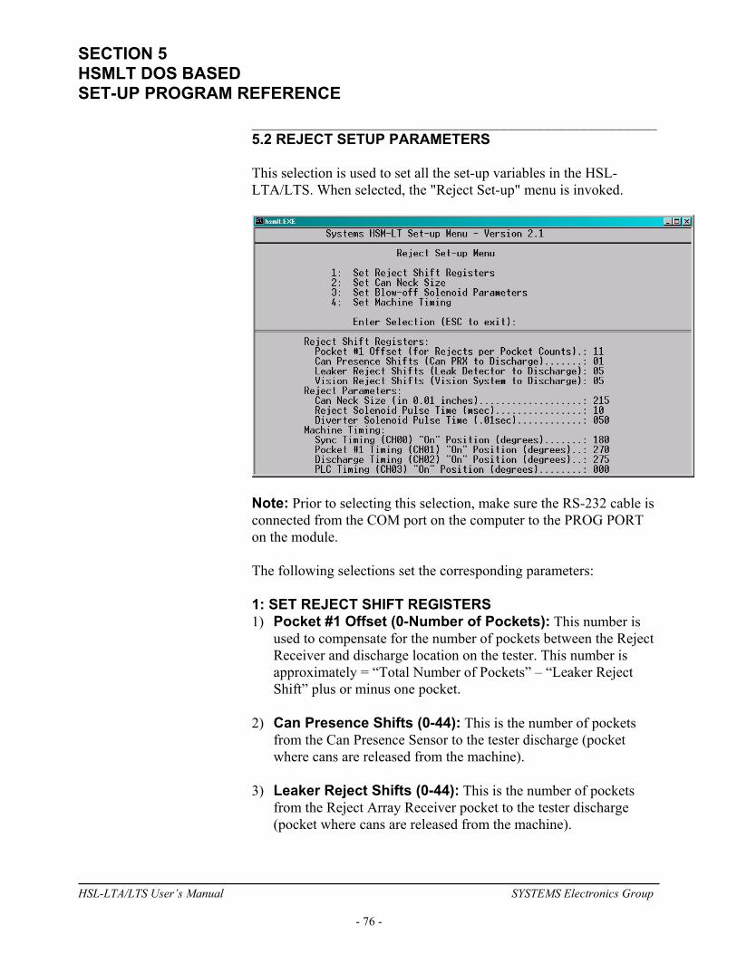
SECTION 5 HSMLT DOS BASED SET-UP PROGRAM REFERENCE
________________________________________________________ 5.2 REJECT SETUP PARAMETERS This selection is used to set all the set-up variables in the HSL-LTA/LTS. When selected, the "Reject Set-up" menu is invoked.
Note: Prior to selecting this selection, make sure the RS-232 cable is connected from the COM port on the computer to the PROG PORT on the module. The following selections set the corresponding parameters: 1: SET REJECT SHIFT REGISTERS 1) Pocket #1 Offset (0-Number of Pockets): This number is
used to compensate for the number of pockets between the Reject Receiver and discharge location on the tester. This number is approximately = “Total Number of Pockets” – “Leaker Reject Shift” plus or minus one pocket.
2) Can Presence Shifts (0-44): This is the number of pockets
from the Can Presence Sensor to the tester discharge (pocket where cans are released from the machine).
3) Leaker Reject Shifts (0-44): This is the number of pockets
from the Reject Array Receiver pocket to the tester discharge (pocket where cans are released from the machine).
HSL-LTA/LTS User’s Manual SYSTEMS Electronics Group
- 76 -
SECTION 5 HSMLT DOS BASED
SET-UP PROGRAM REFERENCE 4) Vision Reject Shifts (0-44): This is the number of pockets
from the vision inspection system reject pocket to the tester discharge (pocket where cans are released from the machine).
2: SET CAN NECK SIZE 1) Can Neck Size (in 0.01 inches): This parameter is used to
calculate when to activate the reject blow-off as a function of the can speed. The can neck size is simply the diameter of the neck at it's most narrow point in 0.01 inches. For example, if the neck measures 2.15" at it's most narrow point, simply enter 215 for the can neck size. The valid range of this value is 180 to 300.
3: SET BLOW-OFF SOLENOID PARAMETERS 1) Reject Solenoid Pulse Time (msec): This is the number of
milliseconds that the reject solenoids will be pulsed for when a bad can is rejected. This is adjusted to get a strong pulse of air to reject the can. Too short of time will result in the can not being fully rejected (jamming). Too long of time will disturb the following can at high speeds also causing jamming. Typically this is set from 10 to 12msec. The valid range for this parameter is 8 to 50msec.
2) Diverter Solenoid Pulse Time (.01sec): This is the amount
of time (in .01seconds) the leaker/vision diverter solenoid (if used) is pulsed for to divert a leaker reject down a separate leakers only reject chute. The valid range for this parameter is 0 to 250 (2.5seconds).
4: SET MACHINE TIMING 1) Sync Timing (CH00): The Sync Timing is used to clock in the
reject data from the Reject Array Receiver, Array Fault Receiver, and the vision system reject signal as well as clock the data from the Can Presence sensor. The Sync Timing should be as far as possible from the occurrence of the above four signals. For the LT-10, this is at 0 degrees, for the LT-16, the is at 180 degrees.
2) Pocket #1 Timing (CH01): The Pocket #1 Timing is used to
reset the pocket count to pocket #1. Set the Pocket #1 Timing 90 degrees following the Sync Timing.
HSL-LTA/LTS User’s Manual SYSTEMS Electronics Group
- 77 -
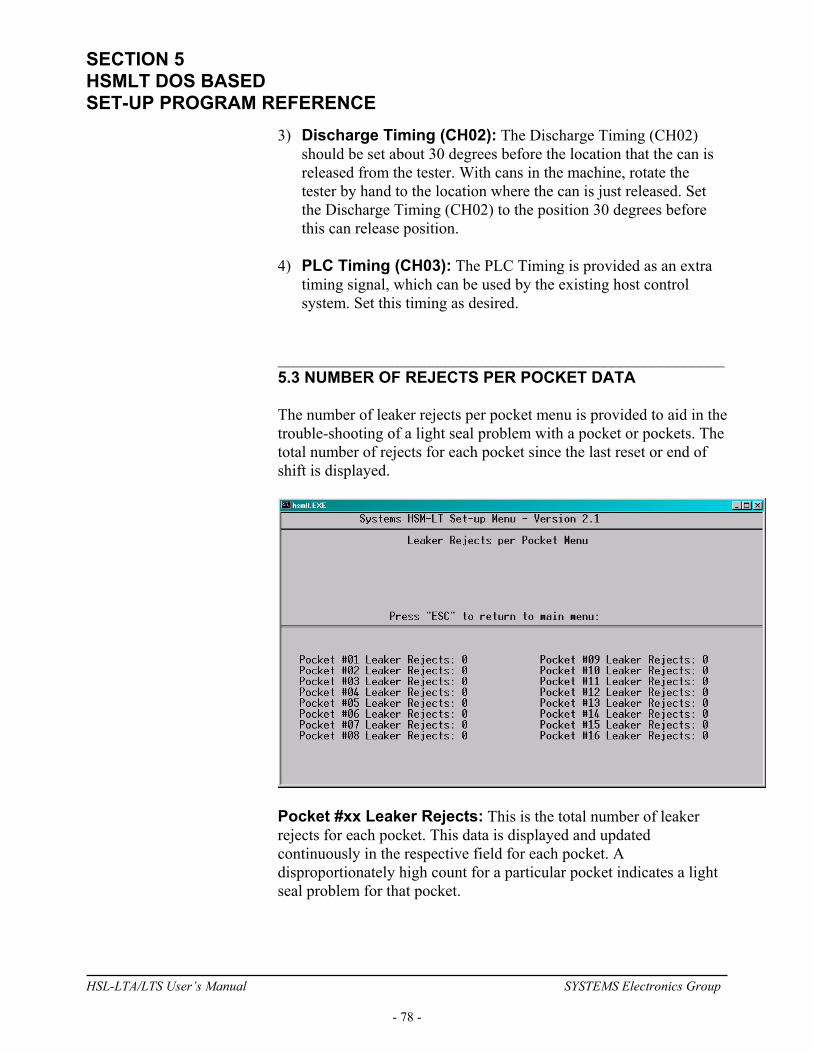
SECTION 5 HSMLT DOS BASED SET-UP PROGRAM REFERENCE
3) Discharge Timing (CH02): The Discharge Timing (CH02) should be set about 30 degrees before the location that the can is released from the tester. With cans in the machine, rotate the tester by hand to the location where the can is just released. Set the Discharge Timing (CH02) to the position 30 degrees before this can release position.
4) PLC Timing (CH03): The PLC Timing is provided as an extra
timing signal, which can be used by the existing host control system. Set this timing as desired.
________________________________________________________ 5.3 NUMBER OF REJECTS PER POCKET DATA The number of leaker rejects per pocket menu is provided to aid in the trouble-shooting of a light seal problem with a pocket or pockets. The total number of rejects for each pocket since the last reset or end of shift is displayed.
Pocket #xx Leaker Rejects: This is the total number of leaker rejects for each pocket. This data is displayed and updated continuously in the respective field for each pocket. A disproportionately high count for a particular pocket indicates a light seal problem for that pocket.
HSL-LTA/LTS User’s Manual SYSTEMS Electronics Group
- 78 -

SECTION 5 HSMLT DOS BASED
SET-UP PROGRAM REFERENCE ________________________________________________________ 5.4 CURRENT SHIFT DATA This selection is used to view the Current Shift data. This data is the totals so far into the shift. This data is transferred to the "Last shift" data when the end of shift input transfers from a "0" to a "1". This can be at the end of either an 8 or 12 hour shift or alternatively could be done at label changes such that the data collected would be for label runs rather than complete shifts. This data cannot be reset, either from this menu or by the operator, only at the "end of shift" input transition.
Note: Prior to selecting this selection, make sure the RS-232 cable is connected from the COM port on the computer to the PROG PORT on the HSMLT module. Total Good Cans Tested: This is the total number of good cans tested so far into the shift. This is essentially a can counter. Total Leaker Rejects: This is the total number of leaker cans rejected by the machine so far into the shift. Total Vision Inspection Rejects: This is the total number of cans rejected by the vision inspection system (if used). Pocket Leaker Rejects: This is the total leaker rejects for each pocket. A disproportionately high count for a particular pocket indicates a light seal problem for that pocket.
HSL-LTA/LTS User’s Manual SYSTEMS Electronics Group
- 79 -
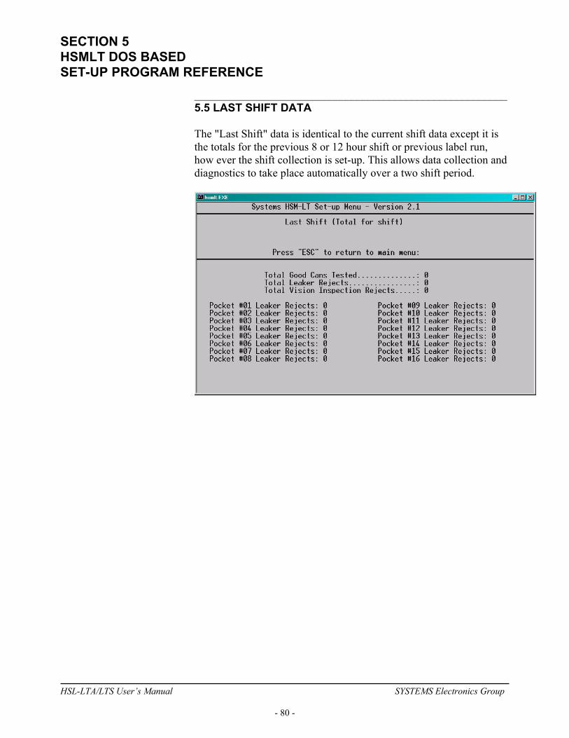
SECTION 5 HSMLT DOS BASED SET-UP PROGRAM REFERENCE
________________________________________________________ 5.5 LAST SHIFT DATA The "Last Shift" data is identical to the current shift data except it is the totals for the previous 8 or 12 hour shift or previous label run, how ever the shift collection is set-up. This allows data collection and diagnostics to take place automatically over a two shift period.
HSL-LTA/LTS User’s Manual SYSTEMS Electronics Group
- 80 -
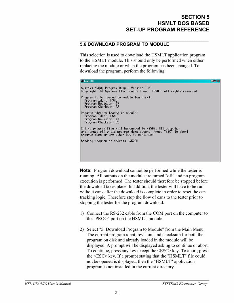
SECTION 5 HSMLT DOS BASED
SET-UP PROGRAM REFERENCE ________________________________________________________ 5.6 DOWNLOAD PROGRAM TO MODULE This selection is used to download the HSMLT application program to the HSMLT module. This should only be performed when either replacing the module or when the program has been changed. To download the program, perform the following:
Note: Program download cannot be performed while the tester is running. All outputs on the module are turned "off" and no program execution is performed. The tester should therefore be stopped before the download takes place. In addition, the tester will have to be run without cans after the download is complete in order to reset the can tracking logic. Therefore stop the flow of cans to the tester prior to stopping the tester for the program download. 1) Connect the RS-232 cable from the COM port on the computer to
the "PROG" port on the HSMLT module. 2) Select "5: Download Program to Module" from the Main Menu.
The current program ident, revision, and checksum for both the program on disk and already loaded in the module will be displayed. A prompt will be displayed asking to continue or abort. To continue, press any key except the <ESC> key. To abort, press the <ESC> key. If a prompt stating that the "HSMLT" file could not be opened is displayed, then the "HSMLT" application program is not installed in the current directory.
HSL-LTA/LTS User’s Manual SYSTEMS Electronics Group
- 81 -
SECTION 5 HSMLT DOS BASED SET-UP PROGRAM REFERENCE
3) Once program download is initiated, program execution will cease, the current address being downloaded will be displayed, and the "RUN" LED on the module will flash continuously.
4) Once the download is complete, the "RUN" LED on the module
will illuminate solid and program execution will resume. Press any key to return back to the "HSMLT" main menu.
5) This selection can also be used to verify the program ident,
revision, and checksum without downloading the program. Perform steps 1 thru 3 above but instead of initiating the download in step 3, simply press the <ESC> key to abort the download once the ident, revision, and checksum have been displayed.
________________________________________________________ 5.7 DOWNLOAD SET-UP DATA TO MODULE This selection is used to download the previously uploaded (saved) set-up variables to the module. This should only be performed when replacing the module. Note: The set-up data consists of the can presence/leaker reject/vision reject shift register presets, the can neck size, and the timing signal set-points. To download the set-up data, perform the following: 1) Connect the RS-232 cable from the COM port on the computer to
the "PROG" port on the HSMLT module. 2) Select "6: Download Set-up data to Module". A prompt will be
displayed asking to continue or abort. To continue, press any key except the <ESC> key. To abort, press the <ESC> key.
3) Once data download is initiated, the current address being
downloaded will be displayed.
Note: Program execution is not ceased, therefore data download can be performed while the machine is running.
4) Once set-up data download is complete, press any key to return to
the "HSMLT" main menu.
HSL-LTA/LTS User’s Manual SYSTEMS Electronics Group
- 82 -

SECTION 5 HSMLT DOS BASED
SET-UP PROGRAM REFERENCE ________________________________________________________ 5.8 UPLOAD (SAVE) SET-UP DATA FROM MODULE This selection is used to save the set-up variables from the HSMLT module to the hard drive (current directory selected). This should be performed anytime any of the set-up variables have been changed. Note: When the set-up variables are changed, they are changed directly in the module, not on the file in the computer. By uploading (saving) the set-up variables to disk, they can be downloaded to the module in the event the module must be replaced. The set-up data consists of the can presence/leaker reject/vision reject shift register presets, the can neck size, and the timing signal set-points. To upload the set-up data, perform the following: 1) Connect the RS-232 cable from the COM port on the computer to
the "PROG" port on the HSMLT module. 2) Select "7: Upload (Save) Set-up data from Module". A prompt
will be displayed asking to continue or abort. To continue, press any key except the <ESC> key. To abort, press the <ESC> key.
3) Once data upload is initiated, the current address being uploaded
will be displayed.
Note: Program execution is not ceased, therefore data upload can be performed while the machine is running.
4) Once set-up data upload is complete, press any key to return to the
"HSMLT" main menu.
HSL-LTA/LTS User’s Manual SYSTEMS Electronics Group
- 83 -
SECTION 5 HSMLT DOS BASED SET-UP PROGRAM REFERENCE
(This Page Intentionally Left Blank)
HSL-LTA/LTS User’s Manual SYSTEMS Electronics Group
- 84 -
SECTION 6 TROUBLE-SHOOTING
The following is provided as a quick reference to aid in the trouble-shooting of the HSL-LTA/LTS. Definitions and causes of the various alarm messages displayed by the HSMLT module is provided as well as a general step-by-step trouble-shooting process. ________________________________________________________ 6.1 HSMLT ALARM MESSAGE DEFINITIONS In addition to the default and set-up messages described in the previous sections, alarm and status messages are displayed on the HSMLT display. These messages correspond to the binary code output on B101.5 (bit0) through B101.7 (bit2). The definitions of these messages are as follows: "Leak Detection Array Fault": This message occurs when a fault in a leak detection array head occurs (Array Fault Receiver did not detect array head LED when array head passed by). Output Code: 001 "Can Jam or Back-up at Discharge": This message is displayed if either a jam occurs at the discharge of the tester (Reject Photo Eye covered continuously) or if the Reject Photo Eye fails. In general, if cans are running into the machine but the Reject Photo Eye does not "see" individual cans coming out, this alarm occurs. Output Code: 010 "Timing Resolver Fail": The timing resolver fail occurs when any of the four timing signals generated in the PLS section fail to change state periodically while the machine is running. Motion must be detected on all four timing signals six seconds after the “Machine Run” input B110.0 turns “on” in order to avoid this fault. Output Code: 011 “Excessive FIFO High Corrections”: This fault occurs when more than five FIFO high corrections (see section 2.10.6) occur within 5 minutes of accrued run time. Normally no more than a few corrections per hour should occur. A “High” correction occurs when either the Can Presence Sensor double clocks a can (unlikely) or the Reject Photo Eye misses a can. Verify the machine set-up be performing the steps in section 6.2. Output Code: 100
HSL-LTA/LTS User’s Manual SYSTEMS Electronics Group
- 85 -
SECTION 6 TROUBLE-SHOOTING
“Excessive FIFO Low Corrections”: This fault occurs when more than five FIFO low corrections (see section 2.10.6) occur within 5 minutes of accrued run time. Normally no more than a few corrections per hour should occur. A “Low” correction occurs when either the Can Presence Sensor misses a can or the Reject Photo Eye double clocks a can. Verify the machine set-up be performing the steps in section 6.2. Output Code: 100 "Clean Blow-off Photo Eye Lenses (Dirty)": This message indicates that the lenses of the Reject Photo Eye (fiber optic cable) mounted on the Reject Blow-off assembly should be cleaned. This occurs when an excess film deposit of contaminants has formed over the fiber optic lenses of the Reject Blow-off Photo Eye, reducing the gain of the eye. If the lenses are not cleaned, the eye will cease to function correctly (causing a Photo Eye Fail alarm) once too much contamination occurs. This fault can also be caused by a damaged fiber optic cable, causing low gain or if the Reject Photo Eye gain potentiometer is set too low. Output Code: 101 "Tester did not Reject Defective Can": This message indicates that the “Reject Verification” sensors in the reject chute did not detect a can rejected when the reject blow-off was activated. This indicates that a problem with the blow-off solenoid, air, or blow-off photo-eye may exist. Verify the operation of the blow-off solenoid by depressing the "Test Blow-off" key on the HSMLT module while the machine is running. A single can should be rejected when the key is depressed. If not, trouble-shoot the reject blow-off system. Output Code: 110 “Can Presence Sensor Failure”: This message is generated when the Reject Photo Eye detects a significantly greater number of cans coming out of the machine than the Can Presence Sensor “sees” coming in. Generally this occurs when the Can Presence Sensor fails (no change of state), or when it misses cans (set too far out to detect all the cans), or is missed timed (“sees” leading edge of can coincident with “Sync” timing). In some cases, this can be caused by the Reject Photo Eye simply double clocking (damaged fiber cables or miss adjusted lenses). Verify the machine set-up be performing the steps in the section 6.2. Output Code: 111
HSL-LTA/LTS User’s Manual SYSTEMS Electronics Group
- 86 -
SECTION 6 TROUBLE-SHOOTING
________________________________________________________ 6.2 CAN TRACKING ERRORS TROUBLE-SHOOTING If the system is intermittently rejecting the wrong can or incurring “Excessive FIFO Correction” faults, perform the following to trouble-shoot the system: 1) Verify the FIFO Error Correction is calibrated correctly. Perform
all the steps in section 2.10.6. If after calibrating the FIFO correction, the system is still not functioning correctly, perform the following steps (2) thru (4).
2) Check the RSV34-MS1 Resolver mounting and resolver coupler
for obvious damage (broken or loose coupler or mount). 3) Check the “Can Presence Sensor” for obvious damage (bent
mounting bracket, sensor damaged, etc.). 4) Check “Reject Photo Eye” and fiber cables for obvious damage
(damaged L2 lenses on fiber cables, crushed or broken fiber cables, fiber cable mounting in Q23SP6 photo eye loose or damaged, Q23SP6 sensor failed, etc.).
5) If no obvious damage is detected in steps (2) thru (4) above,
perform the following steps (6) thru (13). 6) Position the machine at machine zero (see section 2.10.4). From
the “3: Set Machine Timing” selection of the “Set-up” menu, verify the position reads 000 degrees, +/– 20 degrees. If not re-zero the resolver.
HSL-LTA/LTS User’s Manual SYSTEMS Electronics Group
- 87 -

SECTION 6 TROUBLE-SHOOTING
7) Verify 360 degrees per pocket. Position the machine at 0 degrees. A pocket should be aligned with the reset lamp centered in the reset photo diode of a pocket. By hand, move the machine forward one pocket such that the next pocket is centered on the reset lamp, the position should count up thru 359 and again be at 0 degrees. Do this for all the pockets.
Note: The position may deviate +/-20 degrees from pocket to pocket. This is normal and is not a problem. If it does deviate significantly more than +/-20 degrees, perform the following:
a) Using a DVM in AC mode, measure the voltage between R1
and R2 on the HSMLT (M4503) resolver connector. This should read 1.0 to 1.5 VRMS (AC voltage). If no voltage is read, replace the HSMLT (M4503) module (see section 2.11). Be sure the DVM is in AC mode, this is not a DC voltage.
b) Again using the DVM in AC mode, verify the voltage
between S1 and S3 on the HSMLT (M4503) module resolver connector while slowing rotating the machine forward one pocket. The voltage should vary between 0 and 2.0 VRMS. If the voltage always stays at zero as the machine is moved forward, check the resolver wiring for a loose connection. If the wiring is OK, replace the RSV34-MS1 resolver.
c) Check the voltage between S2 and S4 on the HSMLT
(M4503) module resolver connector just as was done for S1 and S3 above. It should read just as S1 and S3 should read.
d) If steps (a) thru (c) above check out OK, check the resolver
coupler. Make sure the key in the resolver shaft is installed and the coupler is tight.
e) If (a) thru (d) did check out OK, but the pocket-to-pocket 0
location is still not right, replace the RSV34-MS1 resolver.
HSL-LTA/LTS User’s Manual SYSTEMS Electronics Group
- 88 -

SECTION 6 TROUBLE-SHOOTING
8) Verify the Can Presence Sensor. The Can Presence Sensor is used
to clock the cans into the FIFO so the set-up of the sensor is critical. Verify the following:
a) Verify the Can sensor “sees” a can when positioned in front of
it. b) Verify the Can sensor is set at about .125” from the body of
can positioned in front of the sensor. Adjust if necessary. c) Determine the position the Can Presence Sensor turns “on”.
With a can in a pocket, rotate the machine forward until the Can Presence Sensor just turns “on”. This position cannot be within +/-60 degrees of the “Sync” timing. Adjust the sensor if necessary to achieve this.
9) Verify the Reject Photo Eye. The fiber optic lenses of the Reject
Photo Eye must be mounted such that the neck of the can breaks the beam. Knowing the neck size, the time the neck of the can breaks the beam of the Reject Photo Eye is used to calculate the speed of the can and thus “lead” the blow-off solenoid correctly at all speeds. In addition, the Reject Photo Eye is used to clock the cans out of the FIFO so the set-up of the Reject Photo Eye is critical. Verify the following:
a) Verify the fiber optic lenses see the neck of the can. With two
cans side by side, the lenses must be able to see thru the valley created by the two necks.
b) Verify the lenses cannot “see” over the top of the can when
the can is pushed or tilted toward the dome. c) Verify the gain potentiometer on the body of the Q23SP6
Photo Eye is fully clockwise (max gain). This is a ¾ turn pot.
10) With the machine running in normal production, verify the positions that the critical inputs come in (see section 2.10.7). These inputs include the Reject Receiver, Array Fault Receiver, Can Presence Sensor, and Vision Reject signal. None of these signals should come in within +/-60 degrees of the “Sync” timing, otherwise FIFO errors may occur.
HSL-LTA/LTS User’s Manual SYSTEMS Electronics Group
- 89 -
SECTION 6 TROUBLE-SHOOTING
11) For aluminum can installations: Verify that the can flow from the discharge is smooth and that the cans are not intermittently bouncing back into the discharge. Since the Reject Photo Eye is used to calculate the speed of the can as it is rejected, and thus “lead” the blow-off based on this speed, the can must flow past the sensor and reject port at a constant rate. If a can goes past the sensor and then is knocked back by the previous can, the reject port will not fire at the right time and a clean reject will not occur. Also, in severe cases, instability in the discharge can flow can cause FIFO error corrections because the Reject Photo Eye may be double clocked when cans bounce back into the machine.
12) For steel can installations: For steel food cans that do not have a
neck, make sure the distance between cans on the magnetic conveyor at the tester top speed is 3/8” or more. The Reject Photo Eye has to “see” the individual cans (beam must be able to pass between individual cans).
13) If after performing the previous steps (1) thru (12), the system is
still not functioning correctly, perform all the steps in the set-up section 2.5.
14) If after performing step (13), the system is still not functioning
correctly, replace the HSMLT (M4503) module and try again. See section 2.11 for details on replacing the module.
HSL-LTA/LTS User’s Manual SYSTEMS Electronics Group
- 90 -
SECTION 6 TROUBLE-SHOOTING
________________________________________________________ 6.3 CAN REJECT PROBLEMS TROUBLE-SHOOTING If the system is having problems cleanly rejecting cans from the discharge conveying into the reject chute, perform the following: Note: The reject can be verified at full production speeds using the “Test Blow-Off” key on the keypad of the HSMLT (M4503) module. Depressing this once will cause one can to be rejected just as a normal reject would occur. Also, this key can be pressed with the machine stopped to verify the reject solenoids. The solenoids will be pulsed for the same time when the key is hit just as if the machine was running. Aluminum Can Installations: 1) Verify that both reject solenoids are firing. Disconnect the air
lines from both solenoids and verify a pulse of air from each solenoid when the “Test Blow-off” key is depressed.
2) Verify air pressure to reject system is 90psi or greater. 3) Verify that the length of the air lines from the reject solenoids to
the reject manifold is less than 4”. Air lines longer than this will increase the response time (solenoid activation to air out manifold) and reduce the pressure at the exit of the manifold.
4) Verify the distance between the face of the reject manifold and
can is 1/4”. If the manifold is placed closer to the can than this, less reject force occurs because air induction to the stream of air at the exit of the manifold is reduced.
5) Verify the manifold is pointed perpendicular or slightly into the
flow of cans. Pointing the manifold slightly into the flow of cans increases the angle that a can will be rejected. Pointing the manifold slightly with the flow of cans will decrease the angle that a can is rejected.
6) Verify the distance (opening in discharge track-work) from the
centerline of the manifold to the lip of the funneling plate is 8”. In general, an opening of less than 8” will not allow the can to cleanly reject at high speeds.
HSL-LTA/LTS User’s Manual SYSTEMS Electronics Group
- 91 -
SECTION 6 TROUBLE-SHOOTING
7) Verify the distance from the centerline of the “Reject Photo Eye” fiber lenses to the centerline of the reject manifold is 5”. This distance is assumed by the system and is used as part of the speed calculation to “lead” when to activate the blow-off. Changing this distance will change where the air hits the can.
8) Verify and if necessary adjust the “Reject Solenoid Pulse” time
(see section 3.5.2 – “2: Set Reject Blow-off Parameters”). 9) Verify and if necessary adjust the “Can Neck Size” (see section
3.5.2 – “2: Set Reject Blow-off Parameters”). The “Can Neck Size” parameter can be used to compensate for the response time of the blow-off solenoids. To advance the blow-off (activate solenoids earlier), make the “Can Neck Size” larger. To retard the blow-off (activate the solenoids later), make the “Can Neck Size” smaller.
HSL-LTA/LTS User’s Manual SYSTEMS Electronics Group
- 92 -

SECTION 6 TROUBLE-SHOOTING
Steel Can Installations: 1) Verify that both reject solenoids are firing. Verify a pulse of air
from the both the nozzle and manifold when the “Test Blow-off” key is depressed.
2) Verify air pressure to reject system is 90psi or greater. 3) Verify that the length of the air line from the reject solenoid to the
reject manifold is less than 4”. Air line longer than this will increase the response time (solenoid activation to air out manifold) and reduce the pressure at the exit of the manifold.
4) Verify vortex nozzle of upper reject solenoid points down at an
angle into the can. This maximizes the reject force. 5) Verify the distance from the centerline of the “Reject Photo Eye”
fiber lenses to the centerline of the reject manifold and nozzle is 5”. This distance is assumed by the system and is used as part of the speed calculation to “lead” when to activate the blow-off. Changing this distance will change where the air hits the can.
6) Verify and if necessary adjust the “Reject Solenoid Pulse” time
(see section 3.5.2 – “2: Set Reject Blow-off Parameters”). 7) Verify and if necessary adjust the “Can Neck Size” (see section
3.5.2 – “2: Set Reject Blow-off Parameters”). The “Can Neck Size” parameter can be used to compensate for the response time of the blow-off solenoids. To advance the blow-off (activate solenoids earlier), make the “Can Neck Size” larger. To retard the blow-off (activate the solenoids later), make the “Can Neck Size” smaller.
HSL-LTA/LTS User’s Manual SYSTEMS Electronics Group
- 93 -
SECTION 6 TROUBLE-SHOOTING
(This Page Intentionally Left Blank)
HSL-LTA/LTS User’s Manual SYSTEMS Electronics Group
- 94 -

SECTION 7 RECOMMENDED SPARES
The following are recommended spares for the HSL-LTA/LTS. These parts are available through Systems Engineering Assoc. Inc. Quantity Part Number Description 1ea. HSMLT Reject Control Module
(SEG) 1ea. RSV34-MS1 Resolver (SEG) 1ea. Q23SP6FPY Photo Eye (Banner) 1ea. PIT43TSSS Sheathed Fiber Cable
(Banner) 2ea. L2 Plastic Fiber Lenses
(Banner) 1ea. Bi10U-G30-AP4X Proximity Sensor (Turck) 1ea. 711C-12-PI-551BA Solenoid (Mac) 1ea. 55B-12-PI-551BA Solenoid (Mac)
HSL-LTA/LTS User’s Manual SYSTEMS Electronics Group
- 95 -
SECTION 7 RECOMMENDED SPARES
(This Page Intentionally Left Blank)
HSL-LTA/LTS User’s Manual SYSTEMS Electronics Group
- 96 -

APPENDIX A DF1 COMMUNICATIONS
________________________________________________________ HARDWARE DF1 communication takes place via the Channel 0 port of the Allen Bradley PLC. The RS-232 cable should be constructed and connected as shown below: S4516-DF1 to PLC5
Internally, the PLC-5 should be set up for RS-232C communication. Refer to the dip-switch settings guide on the side of the processor.
HSL-LTA/LTS User’s Manual SYSTEMS Electronics Group
- A-1 -
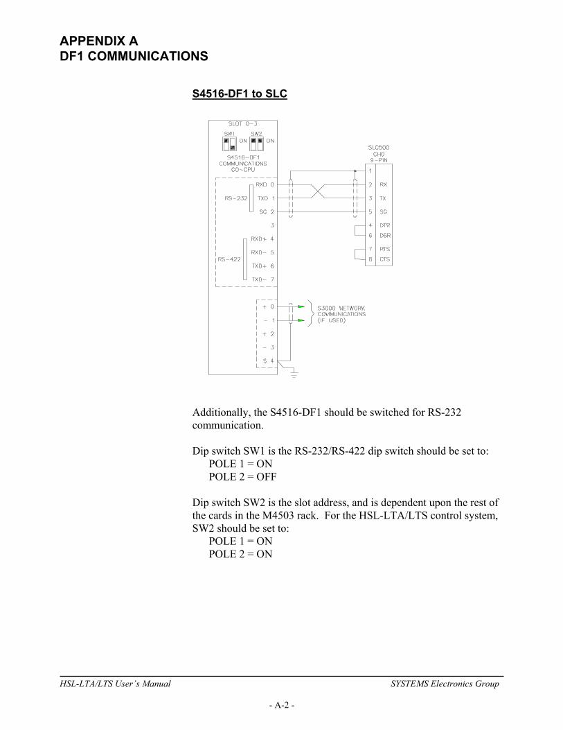
APPENDIX A DF1 COMMUNICATIONS
S4516-DF1 to SLC
Additionally, the S4516-DF1 should be switched for RS-232 communication. Dip switch SW1 is the RS-232/RS-422 dip switch should be set to: POLE 1 = ON POLE 2 = OFF Dip switch SW2 is the slot address, and is dependent upon the rest of the cards in the M4503 rack. For the HSL-LTA/LTS control system, SW2 should be set to: POLE 1 = ON POLE 2 = ON
HSL-LTA/LTS User’s Manual SYSTEMS Electronics Group
- A-2 -
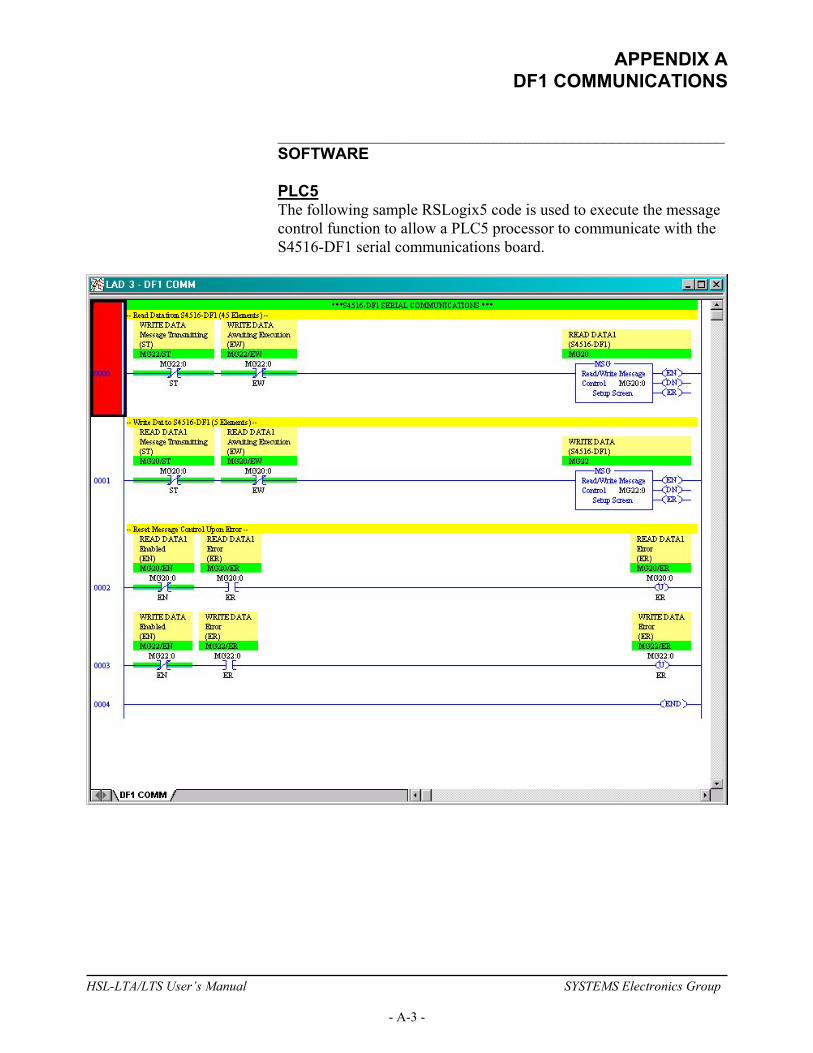
APPENDIX A DF1 COMMUNICATIONS
________________________________________________________ SOFTWARE PLC5 The following sample RSLogix5 code is used to execute the message control function to allow a PLC5 processor to communicate with the S4516-DF1 serial communications board.
HSL-LTA/LTS User’s Manual SYSTEMS Electronics Group
- A-3 -

APPENDIX A DF1 COMMUNICATIONS
SLC500 The following sample RSLogix500 code is used to execute the message control function to allow a SLC500 processor to communicate with the S4516-DF1 serial communications board.
HSL-LTA/LTS User’s Manual SYSTEMS Electronics Group
- A-4 -

APPENDIX A DF1 COMMUNICATIONS
________________________________________________________ USING THE MSG INSTRUCTION READ INSTRUCTION – PLC5 The read message (MSG) command for a PLC5 is setup as follows:
Note: The “Communication Command is PLC3 Word Range Read. The Data Table Address can be any integer file address. The 45 elements read from the M4503 PLC are defined in the last section – Read/Write Data Definitions. The Local Station Address is only necessary to define if communications with the S4516-DF1 is executed over a Data Highway network (via a DataLink Module).
HSL-LTA/LTS User’s Manual SYSTEMS Electronics Group
- A-5 -

APPENDIX A DF1 COMMUNICATIONS
WRITE INSTRUCTION – PLC5 The write message (MSG) command for a PLC5 is setup as follows:
Note: The “Communication Command is PLC3 Word Range Write. The Data Table Address can be any integer file address. The 5 elements written to the M4503 PLC are defined in the last section – Read/Write Data Definitions.
HSL-LTA/LTS User’s Manual SYSTEMS Electronics Group
- A-6 -

APPENDIX A DF1 COMMUNICATIONS
READ INSTRUCTION – SLC500 The read message (MSG) command for a SLC500 is setup as follows:
Note: The Data Table Address can be any integer file address. The 45 elements read from the M4503 PLC are defined in the last section – Read/Write Data Definitions. The Local Station Address is only necessary to define if communications with the S4516-DF1 is executed over a Data Highway network (via a DataLink Module).
HSL-LTA/LTS User’s Manual SYSTEMS Electronics Group
- A-7 -

APPENDIX A DF1 COMMUNICATIONS
WRITE INSTRUCTION – SLC500 The write message (MSG) command for a SLC500 is setup as follows:
Note: The Data Table Address can be any integer file address. The 5 elements written to the M4503 PLC are defined in the last section – Read/Write Data Definitions.
HSL-LTA/LTS User’s Manual SYSTEMS Electronics Group
- A-8 -

APPENDIX A DF1 COMMUNICATIONS
________________________________________________________ CHANNEL 0 SETUP PLC5 The Channel 0 Serial Port should be setup as follows:
Note: The Communication Mode is setup for System (Point-to-Point).
HSL-LTA/LTS User’s Manual SYSTEMS Electronics Group
- A-9 -

APPENDIX A DF1 COMMUNICATIONS
The Channel 0 Options are setup as follows:
The “Detect Duplicate Messages” should be unchecked.
HSL-LTA/LTS User’s Manual SYSTEMS Electronics Group
- A-10 -
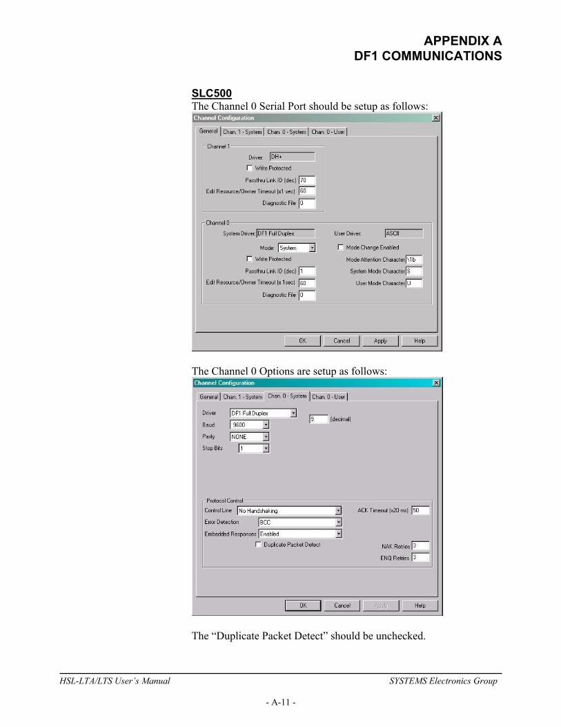
APPENDIX A DF1 COMMUNICATIONS
SLC500 The Channel 0 Serial Port should be setup as follows:
The Channel 0 Options are setup as follows:
The “Duplicate Packet Detect” should be unchecked.
HSL-LTA/LTS User’s Manual SYSTEMS Electronics Group
- A-11 -
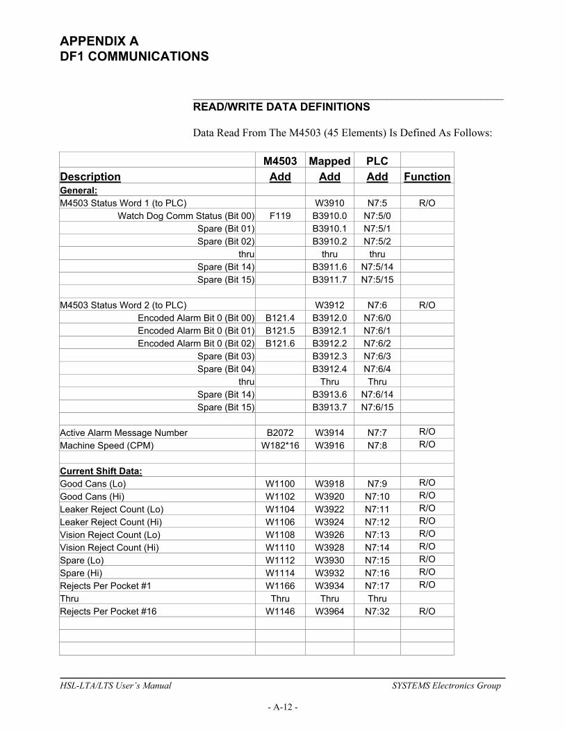
APPENDIX A DF1 COMMUNICATIONS
________________________________________________________ READ/WRITE DATA DEFINITIONS Data Read From The M4503 (45 Elements) Is Defined As Follows:
M4503 Mapped PLC Description Add Add Add Function General: M4503 Status Word 1 (to PLC) W3910 N7:5 R/O
Watch Dog Comm Status (Bit 00) F119 B3910.0 N7:5/0 Spare (Bit 01) B3910.1 N7:5/1 Spare (Bit 02) B3910.2 N7:5/2
thru thru thru Spare (Bit 14) B3911.6 N7:5/14 Spare (Bit 15) B3911.7 N7:5/15
M4503 Status Word 2 (to PLC) W3912 N7:6 R/O
Encoded Alarm Bit 0 (Bit 00) B121.4 B3912.0 N7:6/0 Encoded Alarm Bit 0 (Bit 01) B121.5 B3912.1 N7:6/1 Encoded Alarm Bit 0 (Bit 02) B121.6 B3912.2 N7:6/2
Spare (Bit 03) B3912.3 N7:6/3 Spare (Bit 04) B3912.4 N7:6/4
thru Thru Thru Spare (Bit 14) B3913.6 N7:6/14 Spare (Bit 15) B3913.7 N7:6/15
Active Alarm Message Number B2072 W3914 N7:7 R/O Machine Speed (CPM) W182*16 W3916 N7:8 R/O Current Shift Data: Good Cans (Lo) W1100 W3918 N7:9 R/O Good Cans (Hi) W1102 W3920 N7:10 R/O Leaker Reject Count (Lo) W1104 W3922 N7:11 R/O Leaker Reject Count (Hi) W1106 W3924 N7:12 R/O Vision Reject Count (Lo) W1108 W3926 N7:13 R/O Vision Reject Count (Hi) W1110 W3928 N7:14 R/O Spare (Lo) W1112 W3930 N7:15 R/O Spare (Hi) W1114 W3932 N7:16 R/O Rejects Per Pocket #1 W1166 W3934 N7:17 R/O Thru Thru Thru Thru Rejects Per Pocket #16 W1146 W3964 N7:32 R/O
HSL-LTA/LTS User’s Manual SYSTEMS Electronics Group
- A-12 -
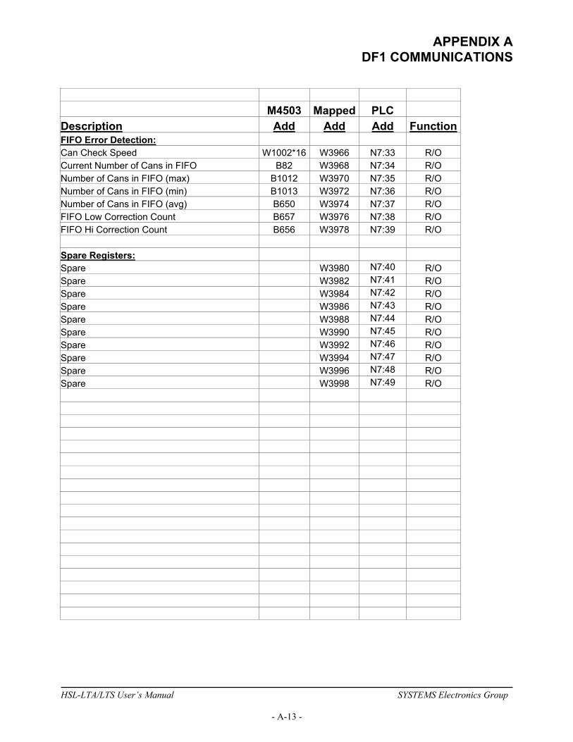
APPENDIX A DF1 COMMUNICATIONS
M4503 Mapped PLC Description Add Add Add Function FIFO Error Detection: Can Check Speed W1002*16 W3966 N7:33 R/O Current Number of Cans in FIFO B82 W3968 N7:34 R/O Number of Cans in FIFO (max) B1012 W3970 N7:35 R/O Number of Cans in FIFO (min) B1013 W3972 N7:36 R/O Number of Cans in FIFO (avg) B650 W3974 N7:37 R/O FIFO Low Correction Count B657 W3976 N7:38 R/O FIFO Hi Correction Count B656 W3978 N7:39 R/O Spare Registers: Spare W3980 N7:40 R/O Spare W3982 N7:41 R/O Spare W3984 N7:42 R/O Spare W3986 N7:43 R/O Spare W3988 N7:44 R/O Spare W3990 N7:45 R/O Spare W3992 N7:46 R/O Spare W3994 N7:47 R/O Spare W3996 N7:48 R/O Spare W3998 N7:49 R/O
HSL-LTA/LTS User’s Manual SYSTEMS Electronics Group
- A-13 -
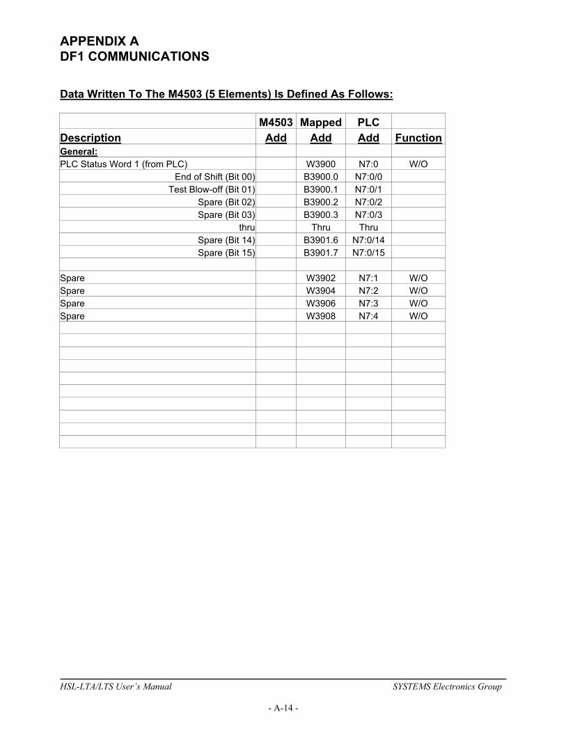
APPENDIX A DF1 COMMUNICATIONS
Data Written To The M4503 (5 Elements) Is Defined As Follows: M4503 Mapped PLC Description Add Add Add Function General: PLC Status Word 1 (from PLC) W3900 N7:0 W/O
End of Shift (Bit 00) B3900.0 N7:0/0 Test Blow-off (Bit 01) B3900.1 N7:0/1
Spare (Bit 02) B3900.2 N7:0/2 Spare (Bit 03) B3900.3 N7:0/3
thru Thru Thru Spare (Bit 14) B3901.6 N7:0/14 Spare (Bit 15) B3901.7 N7:0/15
Spare W3902 N7:1 W/O Spare W3904 N7:2 W/O Spare W3906 N7:3 W/O Spare W3908 N7:4 W/O
HSL-LTA/LTS User’s Manual SYSTEMS Electronics Group
- A-14 -