htb,vf and msc-sg - renold.com · htb,vf and msc-sg superior coupling technology hi-tec marine...
TRANSCRIPT

HTB, VF and MSC-SG
Superior Coupling Technology
Hi-Tec Marine Propulsion Couplings
www.renold.com

Over 50 years of experienceRenold Hi-Tec Couplings has been a world leader in thedesign and manufacture of torsionally flexible couplingsfor over 50 years.
Commitment to Quality and the EnvironmentHaving gained both EN ISO 9001:2008 and EN ISO14001:2004, Renold Hi-Tec Couplings can demonstratetheir commitment to both quality and the environment.
World Class ManufacturingContinual investment is being made to apply the latestmachining and tooling technology. The application oflean manufacturing techniques in an integrated cellularmanufacturing environment establishes efficientworking practices.
Engineering SupportThe experienced engineers at Renold Hi-Tec Couplings aresupported by substantial facilities to enable the ongoingtest and development of product. This includes thecapability for:
• Measurement of torsional stiffness up to 220 kNm
• Full scale axial and radial stiffness measurement
• Misalignment testing of couplings up to 2 metresdiameter
• Static and dynamic balancing
• 3D solid model CAD
• Finite element analysis
TVA ServiceOur resident torsional analysts are able to provide a fullTorsional Vibration Analysis service to investigate acustomer’s driveline and report on the systemperformance. This service, together with the facility fortransient analysis, is available to anyone and is notsubject to purchase of a Renold Hi-Tec product.
Marine Survey Society ApprovalsRenold Hi-Tec Couplings work with all major marinesurvey societies to ensure their products meet the strictperformance requirements.
2 I HTB, VF and MSC-SG Catalogue
Introduction

HTB, VF and MSC-SG Catalogue I 3
www.renold.com
Contents
HTB CouplingFeatures & benefits 4Flywheel mounted 5Technical data 6Design variations 9
VF CouplingFeatures & benefits 10Flywheel mounted 11Shaft to shaft 11Technical data 12Design variations 14
MSC-SG CouplingFeatures & benefits 15Flywheel mounted 16Shaft to shaft 16Weights and Inertias 17Technical data 18Design variations 20Damping characteristics 21Renold Gears and Couplings product range 22
Page No
4 I HTB, VF and MSG-SG Marine Catalogue
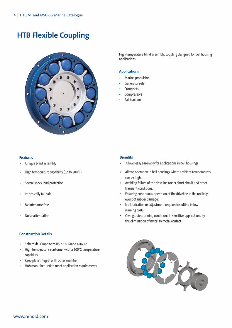
HTB Flexible Coupling
www.renold.com
Features
• Unique blind assembly
• High temperature capability (up to 200°C)
• Severe shock load protection
• Intrinsically fail safe
• Maintenance free
• Noise attenuation
Construction Details
• Spheroidal Graphite to BS 2789Grade 420/12
• High temperature elastomerwith a 200°C temperature
capability
• Keep plate integral with outermember
• Hubmanufactured tomeet application requirements
High temperature blind assembly, coupling designed for bell housingapplications.
Applications
• Marine propulsion
• Generator sets
• Pump sets
• Compressors
• Rail traction
Benefits
• Allows easy assembly for applications in bell housings
• Allows operation in bell housingswhere ambient temperatures
can be high.
• Avoiding failure of the driveline under short circuit and other
transient conditions.
• Ensuring continuous operation of the driveline in the unlikely
event of rubber damage.
• No lubrication or adjustment required resulting in low
running costs.
• Giving quiet running conditions in sensitive applications by
the elimination ofmetal tometal contact.

HTB, VF and MSG-SG Marine Catalogue I 5
www.renold.com
HTB Standard SAE Flywheel to Shaft
Y EA F GD
LB
J
Q x R
W1 J1 W3
J3
W2 J2
M x N
U x V
S x T
C
A F G GY E
Q x R
W1 J1
U x V
S x T
W3 J3
L
D
BJ
B2
C
W2 J2
M x N
Y EA F GD
LB
J
Q x R
W1 J1
U x V
S x T
W3 J3C
W2 J2
M x N
HTB1200 - HTB10000
Dimensions,Weight, Inertia and Alignment
HTB4500 HTB12000 - HTB40000
COUPLING SIZE 0.12 0.2 0.24 0.37 0.73 1.15 2.15 3.86 5.5
A 352.4 466.7 466.7 571.5 466.7 571.5 571.5 673.1 673.1 571.5 673.1 673.1 733.42 860.0B 50.0 50.0 67.0 67.0 69.5 69.5 84.0 84.0 103.0 141.0 141.0 173.0 213 215.0B2 - - - - 20.0 20.0 - - - - - - - -C 3.0 3.0 3.0 3.0 3.0 3.0 4.0 4.0 4.0 4.0 4.0 4.0 7.0 7.0D (STANDARD) 100.0 100.0 112.0 112.0 128.0 128.0 139.0 139.0 166.0 194.0 194.0 236.0 278 276D (DIN 6281) 100.0 85.8 105.0 105.0 105.0 105.0 - - - - - - - -E 156.0 156.0 210.0 210.0 210.0 210.0 256.0 256.0 308.0 256.0 256.0 308.0 346 416.0F 333.4 438.2 438.2 542.9 438.2 542.9 542.9 641.4 641.4 542.9 641.4 641.4 692 820.0G 304.0 304.0 409.0 409.0 409.0 409.0 505.0 505.0 600.0 505.0 505.0 600.0 646 778.0
DIMENSIONS J 10.0 10.0 12.0 12.0 12.0 12.0 16.0 16.0 20.0 16.0 16.0 20.0 20 22.0(mm) L (STANDARD) 106.6 106.6 120.0 120.0 136.0 136.0 150.0 150.0 180.0 205.0 205.0 250.0 300 300.0
M 8 8 8 6 8 6 6 12 12 6 12 12 12 32N 10.5 13.5 13.5 17.0 13.5 17.0 17.0 17.0 17.0 17.0 17.0 17.0 22 21.0L (DIN 6281) 106.6 92.4 92.4 - 92.4 - - - - - - - - -Q 12 12 12 12 16 16 12 12 12 12 12 12 16 16R M12 M12 M16 M16 M16 M16 M20 M20 M24 M20 M20 M24 M24 M24S 6 6 6 6 6 6 6 6 6 6 6 6 - -T M6 M6 M8 M8 M8 M8 M10 M10 M10 M10 M10 M10 - -U 6 6 6 6 6 6 6 6 6 6 6 6 6 6V M12 M12 M14 M14 M14 M14 M16 M16 M20 M16 M16 M20 M24 M24Y (MAX) 85.0 85.0 115.0 115.0 115.0 115.0 150 150 170 150 150 170 215 220.0Y (MIN) 40.0 40.0 50.0 50.0 50.0 50.0 60.0 60.0 60.0 60.0 60.0 60.0 90 110.0Z 16.0 16.0 20.0 20.0 0.0 0.0 29.0 29.0 36.0 29.0 29.0 36.0 - -
RUBBER PER CAVITY 1 1 1 1 2 2 1 1 1 2 2 2 2 2ELEMENTS PER COUPLING 12 12 12 12 24 24 12 12 12 24 24 24 24 24MAXIMUMSPEED (rpm) (1) 3730 2820 2820 2300 2820 2300 2300 1950 1950 2300 1950 1950 1850 1500WEIGHT W1 3.0 3.0 7.0 7.0 10.6 10.6 16.0 16.0 24.4 41.7 41.7 56.0 65.3 98.3(kg) W2 10.0 15.2 22.1 29.2 26.4 34.5 43.2 55.1 77.9 58.6 70.5 112.1 145.2 199.7
W3 (STANDARD) 12.1 12.2 22.9 22.9 22.9 22.9 42.0 42.0 46.7 65.1 65.1 114.5 185.2 262.6W3 (DIN 6281) 12.2 10.3 20.5 - 20.5 - - - - - - - - -TOTAL (W1&W2) 13.0 18.2 29.2 36.2 37.0 45.1 59.2 71.1 102.3 100.3 168.1 210.5 298.0
INERTIA J1 0.03 0.03 0.09 0.09 0.15 0.15 0.26 0.26 0.64 0.98 0.98 1.92 3.07 5.97(kgm2) J2 0.19 0.42 0.75 0.93 0.88 0.92 2.26 3.35 5.39 2.79 3.95 6.63 12.21 23.68
J3 (STANDARD) 0.04 0.04 0.14 0.14 0.17 0.17 0.37 0.37 1.00 0.58 0.58 1.47 2.92 5.96J3 (DIN 6281) 0.03 0.04 0.12 - 0.12 - - - - - - - - -
ALLOWABLEMISALIGNMENTRADIAL (mm) ALIGN 0.25 0.25 0.40 0.40 0.40 0.40 0.40 0.40 0.40 0.40 0.40 0.40 0.40 0.40
MAX 1.00 1.00 1.50 1.50 1.50 1.50 1.50 1.50 1.50 1.50 1.50 1.50 1.50 1.50AXIAL (mm) ALIGN 1.00 1.00 1.00 1.00 1.00 1.00 1.00 1.00 1.00 1.00 1.00 1.00 1.00 1.00
MAX 2.00 2.00 2.50 2.50 2.50 2.50 2.50 2.50 2.50 2.50 2.50 2.50 2.50 2.50CONICAL (degree) 0.50 0.50 0.50 0.50 0.50 0.50 0.50 0.50 0.50 0.50 0.50 0.50 0.50 0.50
COUPLING SIZE 1200 3000 4500 6000 10000 12000 20000 30000 40000
SAE11.5 SAE14 SAE14 SAE18 SAE14 SAE18 SAE18 SAE21 SAE21 SAE18 SAE21 SAE21 SAE24

6 I HTB, VF and MSG-SG Marine Catalogue
HTB Technical Data
www.renold.com
1.1 Torque Capacity - Diesel Engine Drives
The HTB Coupling is selected on the “Nominal TorqueTKN”without
service factors for Diesel Drive applications.
The full torque capacity of the coupling for transient vibrationwhilst
passing throughmajor criticals on run up, is published as the
maximum torqueTKMAX .
(TKMAX = 3 xTKN).
There is additional torque capacity built within the coupling for short
circuit and shock torques, which is 3 x TKMAX.
The published “Vibratory Torque TKW”, relates to the amplitude of the
permissible torque fluctuation. The vibratory torque values shown in
the technical data are at the frequency of 10Hz. The allowable
vibratory torque at higher or lower frequencies fe = TKW
Themeasure used for acceptability of the coupling under vibratory
torque, is published as “Allowable dissipated heat at ambient
temperature 30oC”.
1.2 Transient Torques
Prediction of transient torques inmarine drives can be complex.
Normal installations arewell provided for by selecting couplings based
on the “Nominal Torque TKn“. Transients, such as start up and clutch
manoeuvre, are usually within the “MaximumTorqueTKmax”for the
coupling.
Care needs to be taken in the design of couplingswith shaft brakes, to
ensure coupling torques are not increased by severe deceleration.
Sudden torque applications of propulsion devices such as thrusters or
waterjets, need to be consideredwhen designing the coupling
connection.
2.0 Stiffness Properties
The Renold Hi-Tec Coupling remains fully flexible under all torque
conditions. The HTB series is a non-bonded type operatingwith the
Rubber-in-Compression principle.
2.1 Axial Stiffness
When subject to axial misalignment, the couplingwill have an axial
resistancewhich gradually reduces due to the effect of vibratory
torque.
The axial stiffness of the coupling is torque dependent, and variation is
as shown in the technical data on page 8.
2.2 Radial Stiffness
The radial stiffness of the coupling is torque dependent, and is as
shown in the technical data on page 8.
2.3 Torsional Stiffness
The torsional stiffness of the coupling is dependent upon applied
torque and temperature as shown in the technical data on page 8.
2.4 Prediction of the System
TorsionalVibration
Characteristics
An adequate prediction of the system’s torsional vibration
characteristics, can bemade by the followingmethod:
2.4.1 Use the torsional stiffness as shown in the technical data,
which is based upon datameasured
at a 30˚C ambient temperature.
2.4.2 Repeat the calculation 2.4.1, but using themaximum
temperature correction factor St100 (St200 for Si70 rubber),
and dynamicmagnifier correction factor, M100 (M200 for
Si70 rubber), for the selected rubber. Use tables on page 7 to
adjust values for both torsional stiffness and dynamic
magnifier. ie. CT100 = CTdyn X St100
2.4.3 Review calculations 2.4.1 and 2.4.2 and if the speed range is
clear of criticals which do not exceed the allowable heat
dissipation value as published in the catalogue, then the
coupling is considered suitable for the applicationwith
respect to the torsional vibration characteristics. If there is a
critical in the speed range, then actual temperature of the
couplingwill need to be calculated at this speed.
10Hzfe

HTB, VF and MSG-SG Marine Catalogue I 7
www.renold.com
HTB Technical data
Si70 is considered “standard”
2.6 Temperature Correction Factor
2.7 DynamicMagnifier Correction
Factor
The DynamicMagnifier of the rubber is subject to temperature
variation in the sameway as the torsional stiffness.
2.5 Prediction of the actual coupling
temperature and torsional
stiffness
2.5.1 Use the torsional stiffness as published in the catalogue, this
is based upon datameasured at 30˚C and the dynamic
magnifier at 30˚C. (M30)
2.5.2 Compare the synthesis value of the calculated heat load in the
coupling (PK) at the speed of interest, to the “Allowable Heat
Dissipation” (PKW).
The coupling temperature rise
°C =Tempcoup = x 70 (170 for Si70 rubber)
The coupling temperature =ϑ
ϑ =Tempcoup+ Ambient Temp.
2.5.3 Calculate the temperature correction factor, St, from 2.6 (if the
coupling temperature > 100˚C (200˚C for Si70 rubber), then
use St100 (St200 for Si70 rubber) . Calculate the dynamic
Magnifier as per 2.7. Repeat the calculationwith the new
value of coupling stiffness and dynamicmagnifier.
2.5.4 Calculate the coupling temperature as per 2.5. Repeat
calculation until the coupling temperature agreeswith the
correction factors for torsional stiffness and dynamic
magnifier used in the calculation.
MT =M30St
PKPKW( )
ψT =ψ30 x St
RubberGrade
Si70SM60SM70SM80
Tempmax
°C
200100100100
St
St200 = 0.48St100 = 0.75St100 = 0.63St100 = 0.58
Si70 is considered “standard”
Si70 is considered “standard”
RubberGrade
Si70SM60SM70SM80
DynamicMagnifierat 30°C(M30)
7.5864
DynamicMagnifierat 100°C(M100)
M200 = 15.63
10.79.56.9
RubberGrade
Si70SM60SM70SM80
DynamicMagnifier(M30)
7.5864
RelativeDamping
ψ30
0.830.781.051.57
0.4
0.5
0.6
0.7
0.8
0.9
1
30 40 50 60 70 80 90 100 110 120 130 140 150 160 170 180 190 200
Tem
pera
ture
Cor
rect
ion
Fact
orS
t
Rubber Temperature ºC
Si70 SM60 SM70 SM80
8 I HTB, VF and MSC-SG Catalogue
HTB Technical Data
www.renold.com
End view
COUPLING SIZE 0.12 0.2 0.24 0.37 0.73 1.15 2.15 3.86 5.5
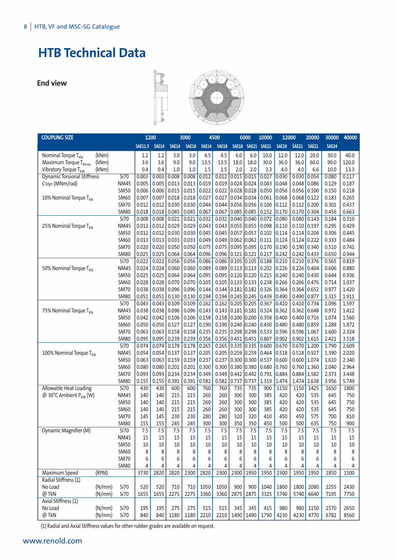
Nominal Torque TKN (kNm) 1.2 1.2 3.0 3.0 4.5 4.5 6.0 6.0 10.0 12.0 12.0 20.0 30.0 40.0MaximumTorqueTKmax (kNm) 3.6 3.6 9.0 9.0 13.5 13.5 18.0 18.0 30.0 36.0 36.0 60.0 90.0 120.0Vibratory Torque TKW (kNm) 0.4 0.4 1.0 1.0 1.5 1.5 2.0 2.0 3.3 4.0 4.0 6.6 10.0 13.3Dynamic Torsional Stiffness Si70 0.003 0.003 0.008 0.008 0.012 0.012 0.015 0.015 0.027 0.030 0.030 0.054 0.080 0.117CTdyn (MNm/rad) NM45 0.005 0.005 0.013 0.013 0.019 0.019 0.024 0.024 0.043 0.048 0.048 0.086 0.129 0.187
SM50 0.006 0.006 0.015 0.015 0.022 0.022 0.028 0.028 0.050 0.056 0.056 0.100 0.150 0.21810%Nominal Torque TKN SM60 0.007 0.007 0.018 0.018 0.027 0.027 0.034 0.034 0.061 0.068 0.068 0.122 0.183 0.265
SM70 0.012 0.012 0.030 0.030 0.044 0.044 0.056 0.056 0.100 0.112 0.112 0.200 0.301 0.437SM80 0.018 0.018 0.045 0.045 0.067 0.067 0.085 0.085 0.152 0.170 0.170 0.304 0.456 0.663Si70 0.008 0.008 0.021 0.021 0.032 0.032 0.040 0.040 0.072 0.080 0.080 0.143 0.184 0.310
25%Nominal Torque TKN NM45 0.012 0.012 0.029 0.029 0.043 0.043 0.055 0.055 0.098 0.110 0.110 0.197 0.295 0.429SM50 0.012 0.012 0.030 0.030 0.045 0.045 0.057 0.057 0.102 0.114 0.114 0.204 0.306 0.445SM60 0.013 0.013 0.033 0.033 0.049 0.049 0.062 0.062 0.111 0.124 0.124 0.222 0.333 0.484SM70 0.020 0.020 0.050 0.050 0.075 0.075 0.095 0.095 0.170 0.190 0.190 0.340 0.510 0.741SM80 0.025 0.025 0.064 0.064 0.096 0.096 0.121 0.121 0.217 0.242 0.242 0.433 0.650 0.944Si70 0.022 0.022 0.056 0.056 0.086 0.086 0.105 0.105 0.188 0.210 0.210 0.376 0.565 0.819
50%Nominal Torque TKN NM45 0.024 0.024 0.060 0.060 0.089 0.089 0.113 0.113 0.202 0.226 0.226 0.404 0.606 0.880SM50 0.025 0.025 0.064 0.064 0.095 0.095 0.120 0.120 0.215 0.240 0.240 0.430 0.644 0.936SM60 0.028 0.028 0.070 0.070 0.105 0.105 0.133 0.133 0.238 0.266 0.266 0.476 0.714 1.037SM70 0.038 0.038 0.096 0.096 0.144 0.144 0.182 0.182 0.326 0.364 0.364 0.652 0.977 1.420SM80 0.051 0.051 0.130 0.130 0.194 0.194 0.245 0.245 0.439 0.490 0.490 0.877 1.315 1.911Si70 0.043 0.043 0.109 0.109 0.162 0.162 0.205 0.205 0.367 0.410 0.410 0.734 1.096 1.597
75%Nominal Torque TKN NM45 0.038 0.038 0.096 0.096 0.143 0.143 0.181 0.181 0.324 0.362 0.362 0.648 0.972 1.412SM50 0.042 0.042 0.106 0.106 0.158 0.158 0.200 0.200 0.358 0.400 0.400 0.716 1.074 1.560SM60 0.050 0.050 0.127 0.127 0.190 0.190 0.240 0.240 0.430 0.480 0.480 0.859 1.288 1.872SM70 0.063 0.063 0.158 0.158 0.235 0.235 0.298 0.298 0.533 0.596 0.596 1.067 1.600 2.324SM80 0.095 0.095 0.239 0.239 0.356 0.356 0.451 0.451 0.807 0.902 0.902 1.615 2.421 3.518Si70 0.074 0.074 0.178 0.178 0.265 0.265 0.335 0.335 0.600 0.670 0.670 1.200 1.790 2.609
100%Nominal Torque TKN NM45 0.054 0.054 0.137 0.137 0.205 0.205 0.259 0.259 0.464 0.518 0.518 0.927 1.390 2.020SM50 0.063 0.063 0.159 0.159 0.237 0.237 0.300 0.300 0.537 0.600 0.600 1.074 1.610 2.340SM60 0.080 0.080 0.201 0.201 0.300 0.300 0.380 0.380 0.680 0.760 0.760 1.360 2.040 2.964SM70 0.093 0.093 0.234 0.234 0.349 0.349 0.442 0.442 0.791 0.884 0.884 1.582 2.373 3.448SM80 0.155 0.155 0.391 0.391 0.582 0.582 0.737 0.737 1.319 1.474 1.474 2.638 3.956 5.749
Allowable Heat Loading Si70 430 430 600 600 760 760 735 735 900 1150 1150 1425 1650 1800@30°C Ambient PKW (W) NM45 140 140 215 215 260 260 300 300 385 420 420 535 645 750
SM50 140 140 215 215 260 260 300 300 385 420 420 535 645 750SM60 140 140 215 215 260 260 300 300 385 420 420 535 645 750SM70 145 145 230 230 280 280 320 320 410 450 450 575 700 810SM80 155 155 245 245 300 300 350 350 450 500 500 635 750 900
DynamicMagnifier (M) Si70 7.5 7.5 7.5 7.5 7.5 7.5 7.5 7.5 7.5 7.5 7.5 7.5 7.5 7.5NM45 15 15 15 15 15 15 15 15 15 15 15 15 15 15SM50 10 10 10 10 10 10 10 10 10 10 10 10 10 10SM60 8 8 8 8 8 8 8 8 8 8 8 8 8 8SM70 6 6 6 6 6 6 6 6 6 6 6 6 6 6SM80 4 4 4 4 4 4 4 4 4 4 4 4 4 4
MaximumSpeed (RPM) 3730 2820 2820 2300 2820 2300 2300 1950 1950 2300 1950 1950 1850 1500Radial Stiffness (1)No Load (N/mm) Si70 520 520 710 710 1050 1050 900 900 1040 1800 1800 2080 2255 2430@TkN (N/mm) Si70 1655 1655 2275 2275 3360 3360 2875 2875 3325 5740 5740 6640 7195 7750Axial Stiffness (1)No Load (N/mm) Si70 195 195 275 275 515 515 345 345 415 980 980 1150 1570 2650@TkN (N/mm) Si70 840 840 1180 1180 2210 2210 1490 1490 1790 4230 4230 4770 6782 8560
COUPLING SIZE 1200 3000 4500 6000 10000 12000 20000 30000 40000
SAE11.5 SAE14 SAE14 SAE18 SAE14 SAE18 SAE18 SAE21 SAE21 SAE18 SAE21 SAE21 SAE24
(1) Radial and Axial Stiffness values for other rubber grades are available on request.

HTB, VF and MSG-SG Marine Catalogue I 9
www.renold.com
HTB Design Variations
TheHTB coupling can be adapted tomeet customer requirements as, can be seen from some of the design variations
below. For amore comprehensive list contact Renold Hi-Tec.
Coupling to Suit Existing Hub Shaft to Shaft Coupling
Reversed InnerMember Coupling Spacer Coupling
Existing hub fitment. Coupling innermember designed to suitexisting hub design.
Shaft to Shaft Coupling. Designed for use on electricmotordrives and power take off applications.
Couplingwith reversed innermember to increase distancebetween flywheel face and shaft end.
Spacer coupling. Used to increase the distance between shaftends and allow easy access to driven and drivingmachine.
10 I HTB, VF and MSC-SG Catalogue
VF Highly Flexible Coupling
www.renold.com
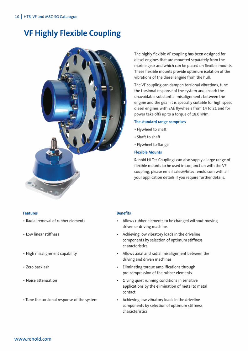
The highly flexible VF coupling has been designed for
diesel engines that are mounted separately from the
marine gear and which can be placed on flexible mounts.
These flexible mounts provide optimum isolation of the
vibrations of the diesel engine from the hull.
The VF coupling can dampen torsional vibrations, tune
the torsional response of the system and absorb the
unavoidable substantial misalignments between the
engine and the gear, it is specially suitable for high speed
diesel engines with SAE flywheels from 14 to 21 and for
power take offs up to a torque of 18.0 kNm.
The standard range comprises
• Flywheel to shaft
• Shaft to shaft
• Flywheel to flange
Flexible Mounts
Renold Hi-Tec Couplings can also supply a large range of
flexible mounts to be used in conjunction with the VF
coupling, please email [email protected] with all
your application details if you require further details.
Features Benefits
• Radial removal of rubber elements • Allows rubber elements to be changed without moving
driven or driving machine.
• Low linear stiffness • Achieving low vibratory loads in the driveline
components by selection of optimum stiffness
characteristics
• High misalignment capability • Allows axial and radial misalignment between the
driving and driven machines
• Zero backlash • Eliminating torque amplifications through
pre-compression of the rubber elements
• Noise attenuation • Giving quiet running conditions in sensitive
applications by the elimination of metal to metal
contact
• Tune the torsional response of the system • Achieving low vibratory loads in the driveline
components by selection of optimum stiffness
characteristics

HTB, VF and MSG-SG Marine Catalogue I 11
www.renold.com
VF Flexible Coupling - Dimensional Data
Flywheel to shaft Flywheel to shaft with adaptor plate Shaft to shaft
SAE14 SAE18 Shaft-Shaft SAE18 SAE21 Shaft-Shaft SAE21 Shaft-ShaftA 466.7 571.5 - 571.5 673.1 - 673.1 -B1 254 265 404 310 326 485 340 525B2 - 13 - - 19 - - -D 150 150 150 175 175 175 185 185E 174 174 174 219 219 219 244 244E1 - - 174 - - 219 - 244F 438.15 542.92 - 542.92 641.35 - 641.35 -G 475 475 475 582 582 582 685 685G1 - 493 - - 583 - - -J 6 15 - 6 20 - 6 -L1 128.8 139.8 153.8 165.8 181.8 196.8 194.8 230.8L2 - - 278.8 - - 340.8 - 379.8S, Qty 8 12 - 12 12 - 12 -U, Dia 13 17 - 17 17 - 17 -Y (Max) 120 120 120 150 150 150 170 170SET 131.4 142.4 131.4 168.6 184.6 168.6 199.8 199.8
Weight W1 7.65 24.23 7.65 13.48 45.42 13.48 24.24 24.24(kg) W2 28.9 28.9 28.9 56.23 56.23 56.23 92.54 92.54
W3 18.3 18.3 18.3 35.34 35.34 35.34 46.16 46.16W4 - - 41.21 - - 74.01 - 114.77
Inertia J1 0.262 0.756 0.262 0.663 3.331 0.663 1.619 1.619(Kg m²) J2 0.897 0.897 0.897 2.625 2.625 2.625 5.646 5.646
J3 0.123 0.123 0.123 0.383 0.383 0.383 0.640 0.640J4 - - 0.809 - - 2.166 - 4.984
VF18000Coupling Size
Dim
ensi
ons,
mm
00001FV0005FV
(1)
(1)
(1) Weights and Inertias based on maximum bore diameter.

12 I HTB, VF and MSC-SG Catalogue
VF Flexible Coupling - Technical Data
www.renold.com
TECHNICAL DATAVF COUPLING 5000 10000 18000
Rubber Grade F50 F60 F70 F50 F60 F70 F50 F60 F70Nominal Torque TKN 1. kNm 4.0 5.0 5.0 8.0 10.0 10.0 14.4 18.0 18.0Transient Torque TKmax1 2. kNm 5.2 7.5 7.5 10.7 15.0 15.0 19.2 27.0 27.0Maximum Torque TKmax2 3. kNm 12.0 15.0 15.0 24.0 30.0 30.0 43.2 54.0 54.0Maximum Torque Range∆Tmax 4. kNm 5.0 7.0 9.0 10.0 14.0 18.0 18.0 25.0 32.0Vibratory Torque TKW 5. kNm 1.55 1.67 1.67 2.67 3.20 3.33 4.80 5.75 6.00Dyn' Torsional Stiffness CTdyn 6. kNm/rad 25 35 75 50 68 148 90 128 278Allowable Heat Loading @30oC PKw 7. W 195 310 340 280 400 430 370 500 565Dynamic Magnifier 8. M 8.0 5.2 3.5 8.0 5.2 3.5 8.0 5.2 3.5Maximum Speed 9. RPM 2460 2820 2000 2300 1800 1950Radial misalignment ∆ K'r 10. mm 4.0 3.0 2.0 6.0 4.5 3.0 8.0 6.0 4.0Radial misalignment installation 0.5 0.4 0.3 0.7 0.5 0.4 1.0 0.7 0.5Radial Stiffness Cr N/mm 440 690 1500 870 1400 2900 1600 2550 5500Axial misalignment ∆ Ka1 11 1.2 1.5 2Axial misalignment ∆ Ka2 12 mm 3.5 4.5 6.0Axial misalignment installation 0.3 0.4 0.6Axial Load @ 1 mm 13kN 0.2 0.15 0.42
A simple verification of the system's torsional vibrationcharacteristic can be made by analysis at the extremesof the coupling allowable temperature to ensure thatwithin this range there are no criticals which exceedthe allowable heat dissipation values.
Assume torsional stiffness and dynamic magnifier aspublished above, i.e. at 30°C and 10 Hz.
Analyse the torsional system to determine criticalswithin the speed range.
Repeat the analysis after using this spreadsheet todetermine coupling stiffness and magnifier at 100°C.
Review the analysis and if the speed range is clear ofcriticals which exceed the heat dissipation values inthe technical data then the coupling can be consideredsuitable for the application, with respect to thetorsional vibration characteristics.
If there is a critical within the speed range, then theactual rubber temperature, vibratory torque andfrequency should be calculated at this speed.
1.1 Prediction of Actual Coupling Torsional Stiffnessand Dynamic Magnifier
Analyse the torsional system using as a starting pointthe torsional stiffness and dynamic magnifier aspublished above. This is based on data at 30°C.
Compare the synthesis value of the calculatedheat load in the coupling (PK) at the speed of interestto the Allowable Heat Dissipation (PKW)
The rise in rubber temperature:
°C rise = (PK / PKW) x 70
The rubber temperature ϑ = °C rise + AmbientTemperature
The torsional stiffness and dynamic magnifier of thecoupling is dependent upon, rubber temperature,vibratory torque and frequency. In order to simplify thedetermination of the torsional stiffness and dynamicmagnifier of the coupling with these variables acomputer programme has been produced to calculatethese values. This program is accessible through theRenold website www.renold.com. The program islocated under ‘Useful Tools’. From the home page go to‘Support’ and then ‘International Links and Tools’ fromthe drop down menu. The progam VF TorsionalStiffness’ is located in ‘Useful Tools’. The program ispassword protected and you will need to contact theRenold Hi-Tec Sales office to be issued with a password.
1.2 Torsional Responsibility
The responsibility for ensuring that there are notorsional resonances within the operating speed rangerests with the final assembler. Renold Hi-Tec Couplingsas a component supplier is not responsible for suchcalculation and can not accept any liability for couplingdamage or gearbox noise or damage caused bytorsional vibrations. Renold Hi-Tec Couplingsrecommend that a torsional vibration calculation iscarried out on the complete drive train prior to start upof the machinery to ensure that the loading on theequipment within the system are within themanufactures declared allowable value for loading.Renold Hi-Tec Couplings can provide a TorsionalVibration Analysis to help customers to investigatetheir drivelines.
1.0 Prediction of the System Torsional VibrationCharacteristics
HTB, VF and MSG-SG Marine Catalogue I 13
www.renold.com
VF Flexible Coupling - Technical Data
1. Select coupling TKN to match the nominal torque of the engine, without considering transient peak torques.The values of TKN , TKmax and TKW are based on an ambient temperature of 30°C. For high ambient temperatures (above 60°C)or high thermal loads a factor of 80% should be applied to TKN, TKmax and TKW
2. TKmax1 refers to a normal transient torque e.g. stops and starts
3. TKmax2 refers to an abnormal transient torque e.g. short circuit torque.
4. Maximum Torque Range ∆Tmax refers to the torque range during a normal transient e.g. stops and starts
5. TKW is the permissible vibratory torque, but must be considered in conjunction with the synthesis value of power loss loading.TKW is the permissible vibratory torque at 10 Hz, for other frequencies, fe : TKW = (10 / fe)0.5
6. The value of dynamic torsional stiffness, Ctdyn, was tested at Frequency of 10 Hz, rubber temperature of 30°C and vibratorytorque of TKW. At other temperatures the dynamic torsional stiffness, Ctdyn, can be established from 1.1.
7 For temperatures above 30°CAllowable PKw = PKw30 (110 - Temp°C) / 80The power loss should be calculated for each order of vibration and added by: Σ Τwi
2 ω / 2 CTdyn ΜWhere:
Twi = vibratory torque at order i (kNm)ω = Frequency (rad/sec)CTdyn = dynamic torsional stiffness (kNm/rad)i = order numberM = dynamic Magnifier
8. The value of quoted dynamic Magnifier, M, was tested at 30°C. For other temperatures M can be determined from 1.1.Relative damping, ψ = 2π / M
9. Couplings may be supplied for higher speed, contact Renold.
10. Steady state Radial misalignment, ∆Wr should not exceed the permissible radial displacement, ∆Kr
∆Kr can be calculated using the computer program, see 1.1.
11. ∆Ka1 is dynamic misalignment tested to 106 cycles
12. ∆Ka2 is steady misalignment typically due to thermal growth.
13. The axial load at 1mm is shown as the axial stiffness is non linear, refer to Renold for other values.

14 I HTB, VF and MSC-SG Catalogue
VF Design Variations
www.renold.com
Spacer Coupling Couplingwith Drive Plates
Shaft to Shaft Coupling Couplingwith Radial Support Bearing
Spacer Coupling. Used to increase the distance between theFlywheel face and the shaft end.
Drive Plate Coupliong. Ensuring continuous operation of thedriveline in the event of rubber failure.
Shaft to shaft Coupling. Designed for use on electricmotordrives and power take off applications.
Radial support bearing. Designed to carry radial loads.
HTB, VF and MSG-SG Marine Catalogue I 15
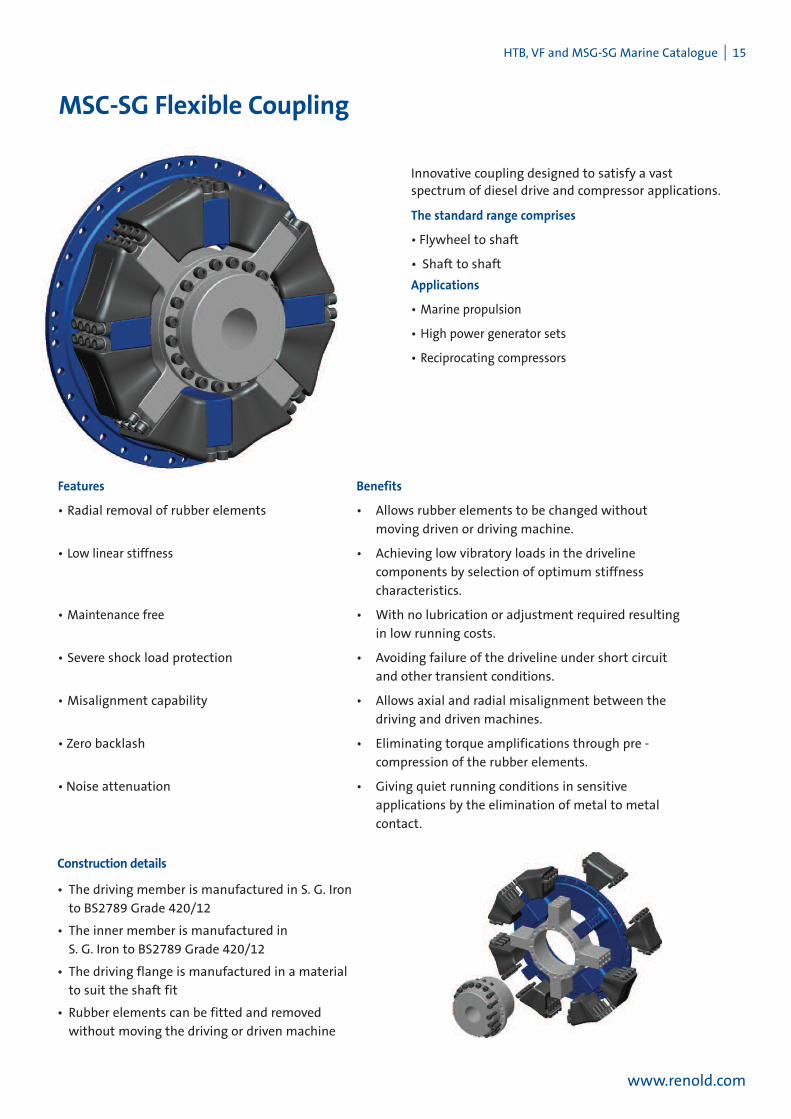
MSC-SG Flexible Coupling
Innovative coupling designed to satisfy a vastspectrum of diesel drive and compressor applications.
The standard range comprises
• Flywheel to shaft
• Shaft to shaft
Applications
• Marine propulsion
• High power generator sets
• Reciprocating compressors
Features Benefits
• Radial removal of rubber elements • Allows rubber elements to be changed without
moving driven or driving machine.
• Low linear stiffness • Achieving low vibratory loads in the driveline
components by selection of optimum stiffness
characteristics.
• Maintenance free • With no lubrication or adjustment required resulting
in low running costs.
• Severe shock load protection • Avoiding failure of the driveline under short circuit
and other transient conditions.
• Misalignment capability • Allows axial and radial misalignment between the
driving and driven machines.
• Zero backlash • Eliminating torque amplifications through pre -
compression of the rubber elements.
• Noise attenuation • Giving quiet running conditions in sensitive
applications by the elimination of metal to metal
contact.
Construction details
• The driving member is manufactured in S. G. Iron
to BS2789 Grade 420/12
• The inner member is manufactured in
S. G. Iron to BS2789 Grade 420/12
• The driving flange is manufactured in a material
to suit the shaft fit
• Rubber elements can be fitted and removed
without moving the driving or driven machine
www.renold.com

16 I HTB, VF and MSC-SG Catalogue
MSC-SG Flywheel to Shaft
www.renold.com
COUPLING SIZE 20 31.5 40 63 80STD SAE21
A 680 673 790 860 995 1070A1 690 800 870 1010 1090B 426 509 557 639.5 732C 46 46 54 57 65.5 89D 200 200 245 265 300 346D1 180 210 235 274 297E 239 239 259 319 337 417E1 290 340 380 440 475F 650 641.35 755 820 950 1025G 609 609 706 833 871 1041J 17 17 18 19 22 29L 162 162 196 219 246 295
DIMENSIONS N 20 20 20 20 20 20(mm) P M16 M16 M20 M20 M24 M24
Q 64 64 64 64 80 80R M16 M16 M18 M22 M20 M30S 32 24 32 32 32 32S1 32 32 32 32 32T 17 17 19 21 23 25T1 M16 M18 M20 M22 M24W 246 246 299 322 365 435X 330 330 380 445 460 567MAX. Y 160 160 180 225 225 278MIN. Y 90 90 105 120 155 170MAX. Y1 180 210 235 273 297MIN. Y1 90 105 120 155 170
TIGHTENINGTORQUE FOR R (Nm) 220 220 250 470 360 1250TIGHTENINGTORQUE FOR P (Nm) 220 220 360 360 625 625
MSC-SG Flywheel to Shaft MSC-SG Shaft to Shaft
Dimensions andTighening Torques

HTB, VF and MSG-SG Marine Catalogue I 17
www.renold.com
MSC-SG Shaft to Shaft
(1) Weights and inertias are based on minimum bore diameter.
(2) For operation above 80% of the declared maximum coupling speed it is recommended that the coupling is balanced.
(3) Installations should be initially aligned as accurately as possible. In order to allow for deterioration in alignment over time it is recommended thatinitial alignment should not exceed 25% of the above noted data. The forces on the driving and driven machinery should be calculated to ensurethat these do not exceed the manufacturers allowables.
Weights, Inertia, Speed and Alignment
MSC-SG Shaft to Shaft MSC-SG Flywheel to Shaft
COUPLING SIZE 20 31.5 40 63 80STD SAE21
WEIGHT W1 131.5 131.5 205.8 323.0 376.6 675.4(kg) W2 89.2 88.2 139.5 200.3 274.6 412.8
W3 147.0 220.0 287.3 443.1 599W1+W2 220.7 219.7 345.3 523.3 651.2 1088.2
INERTIA (2) J1 3.3 3.3 7.1 16.7 21.6 51.85(kgm2) J2 5.5 5.4 11.4 22.2 33.5 69.51
J3 5.1 10.0 14.9 31.6 51.4Rubber Elements per Coupling 8 8 8 8 8 8MaximumSpeed (rev/min) 2050 2050 1700 1600 1350 1250ALLOWABLEMISALIGNMENTRADIAL (mm) 6.0 6.0 6.0 8.0 8.0 9.0AXIAL (mm) 6.0 6.0 6.0 8.0 8.0 9.0CONICAL (degree) 0.5 0.5 0.5 0.5 0.5 0.5
Weights and Inertias are based on minimum bore diameter

18 I HTB, VF and MSC-SG Catalogue
MSC-SG Technical Data
www.renold.com
1.1 Torque Capacity - Diesel Engine Drives
TheMSC-SGCoupling is selected on the “nominal
torqueTKN”without service factors.
The full torque capacity of the coupling for transient
vibrationwhilst passing throughmajor criticals on run up
is published as theMaximumTorqueTKMAX
TKMAX = 3 X TKN.
There is additional torque capacity built within the
coupling for short circuit torques.
The Published “VibratoryTorque, TKW”is a fatigue
function according toDIN740 and not so significant in
diesel engine drives, the vibratory torque values shown in
theTechnical Data are at a frequency of 10Hz. The
measure acceptability of the coupling for vibrating drives
is published as “Allowable DissipatedHeat at Ambient
Temperature 30°C”.
1.2 Transient Torques
Prediction of transient torques in amarine drive can be
more complex. Normal installations arewell provided by
the selection of the coupling based on the “Nominal
TorqueTKN.”Transients such as start up and clutch
manoeuvre are usuallywithin the “MaximumTorque”
TKMAX for the coupling.
Care needs to be taken in the design of couplingswith
shaft brakes to ensure the coupling torques are not
increased by severe deceleration.
Sudden torque applications of propulsion devices such as
the thrusters orwater jets need to be consideredwhen
designing the coupling connection.
2.0 Stiffness Properties
TheMSC-SG coupling consists of rubber elements in
compression and in tension. It is available in four different
stiffnesseswhich are F60, F70, a combination of F60 and
F50 and a combination of F70 and F60. The coupling
rubber grade is defined as shownbelow:
F (compression elements) - F (tension elements)
For example F60 - F50 is a couplingwith F60 rubber in the
compression elements and F50 in the tension elements.
The harder rubber should always be used in the
compression elements therefore it is important to know
the direction of rotation of the coupling to ensure that
the elements are fitted in the correct position.
If all the elements are of one rubber hardness, that is F60
- F60, the direction of rotation is not required.
2.1 Axial Stiffness
The axial stiffness of the coupling is linear and
independent of applied torque as shownon page 19.
2.2 Radial Stiffness
The radial stiffness of the coupling is linear and
independent of applied torque as shownon page 19.
2.3 Torsional Stiffness
The torsional stiffness of the coupling is linear as shown
on page 19, but it should be corrected for temperature as
per graph 2.3.1 below.
2.4 DynamicMagnifier
TheDynamicMagnifier of the rubber is dependent on
rubber temperature and can be established fromgraph
2.4.1 below
2
3
4
5
6
7
8
9
10
11
30 40 50 60 70 80 90 100
DY
NA
MIC
MA
GN
IFIE
RM
T
RUBBER TEMPERATURE °C
2.4.1 Dynamic MagnifierF60-F50 F60-F60 F70-F60 F70-F70
0.98
1
0.96
0.94
0.92
0.9
0.88
0.86
0.8430 40 50 60 70 80 90 100
TEM
PE
RAT
UR
EC
OR
RE
CTI
ON
FAC
TOR
St
RUBBER TEMPERATURE °C
2.3.1 Temperature Correction Factor for all rubber grades

HTB, VF and MSG-SG Marine Catalogue I 19
www.renold.com
2.5 Prediction of the systemtorsional vibration characteristics
An adequate prediction of the system torsional vibration
characteristics can bemade by the followingmethod.
2.5.1 Use the torsional stiffness as published below
which is based upon datameasured at a 30°C
ambient temperature.
2.5.2 Repeat the calculationmade as 2.5.1 but using
themaximum temperature correction factor
and dynamicmagnifier at 100°C (St100 and
M100) for the rubber selected for both torsional
stiffness and dynamicmagnifier from the graph
on page 18.
2.5.3 Review the calculations 2.5.1 and 2.5.2 and if
the speed range is clear of criticalswhich do
not exceed the allowable heat dissipation value
as published in the catalogue, the coupling is
then considered suitable for the application
with respect to the torsional vibration
characteristics. If there is a critical in the speed
range the actual temperature of the coupling
will need to be calculated at this speed.
2.6 Prediction of the actual couplingtemperature and torsionalstiffness
2.6.1 Use the torsional stiffness as published below
which is based upon datameasured at a 30°C
and the dynamicmagnifier at 30°C. (M30)
2.6.2 Compare the synthesis value of the calculated
heat load in the coupling (Pk) at the speed of
interest to the “AllowedHeat Dissipation”(Pkw).
The coupling temperature rise
ºC =Tempcoup = x 70
The coupling rubber temperature =
=Tempcoup + Ambient Temp
2.6.3 Calculate the temperature correction factor Stfrom2.3.1 (if the coupling temperature >
100°C, then use St100). Establish the dynamic
magnifier from2.4.1. Repeat the calculation
with the new value of coupling stiffness and
dynamicmagnifier.
2.6.4 Calculate the coupling temperature as per 2.6.
Repeat calculation until the coupling
temperature agreeswith the calculation factors
for torsional stiffness and dynamicmagnifier
used in the calculation.
PKPKW( )
MSC-SGTechnical DataCOUPLING SIZE 20 31.5 40 63 80
NORMALTORQUETKN (kNm) F60-F50 20.0 31.5 40.0 63.0 80.0F60-F60 20.0 31.5 40.0 63.0 80.0F70-F60 25.0 40.0 50.0 80.0 100.0F70-F70 25.0 40.0 50.0 80.0 100.0
MAXIMUMTORQUETKmax (kNm) F60-F50 60.0 94.5 120.0 189.0 240.0F60-F60 60.0 94.5 120.0 189.0 240.0F70-F60 60.0 94.5 120.0 189.0 240.0F70-F70 60.0 94.5 120.0 189.0 240.0
VIBRATORYTORQUETKW (kNm) F60-F50 5.6 8.8 11.5 17.5 22.4F60-F60 5.6 8.8 11.5 17.5 22.4F70-F60 7.0 11.5 14.0 22.4 28.0F70-F70 7.0 11.5 14.0 22.4 28.0
ALLOWABLE DISSIPATEDHEAT F60-F50 660 715 875 1100 1250AT AMB. TEMP. 30°C PKW (W) F60-F60 660 715 875 1100 1250
F70-F60 680 780 1075 1250 1400F70-F70 680 780 1075 1250 1400
DYNAMICTORSIONAL F60-F50 0.29 0.45 0.57 0.90 1.10STIFFNESS CTdyn (MNm/rad) F60-F60 0.36 0.56 0.71 1.12 1.40
F70-F60 0.63 1.00 1.27 2.00 2.50F70-F70 0.89 1.40 1.75 2.80 3.20
RADIAL STIFFNESS Kr (N/mm) F60-F50 1.8 2.3 2.3 2.6 3.0F60-F60 2.3 3 3.1 3.5 4.0F70-F60 3.4 4.4 4.5 5.1 5.8F70-F70 4.5 5.8 6 6.7 7.6
AXIAL STIFFNESS Ka (N/mm) F60-F50 1.7 2 2.1 2.5 2.8F60-F60 2 2.5 2.6 3 3.3F70-F60 3 3.9 4 4.5 5.0F70-F70 3.7 4.7 4.8 8.2 9.2
DYNAMICMAGNIFIER (M) F60-F50 7.0 7.0 7.0 7.0 7.0AT AMB. TEMP. 30°C F60-F60 5.2 5.2 5.2 5.2 5.2
F70-F60 4.4 4.4 4.4 4.4 4.4F70-F70 3.5 3.5 3.5 3.5 3.5

20 I HTB, VF and MSC-SG Catalogue
MSC-SG Design Variations
www.renold.com
Cardan Shaft Coupling Lightweight Anti-Magnetic Coupling
Couplingwith Radial Support Bearing Vertical Coupling
Cardan shaft coupling to give highmisalignment capability, lowaxial and angular stiffness and high noise attenuation.
Aluminium coupling for use onmilitary applications requiringlowweight, highmisalignment and lowmagnetic permeability.
Couplingwith radial support bearing for high speedapplications or to support intermediate shafts.
Couplingwith brake disc, radial support bearing and end platefor vertical applications.
TheMSC-GS coupling is available in both flywheel to shaft and shaft to shaft applications. TheMSC-SG coupling can be adapted tomeet customer needs as can be seen from some of the design variations shown below.
Spacer Coupling Adaptor Plate Coupling
Spacer coupling to increase the distance between the flangefaces and to allow easy access to driven and drivingmachines.
Adaptor plate coupling for adapting standardMSC-SG
coupling tomeet customer requirements.

HTB, VF and MSG-SG Marine Catalogue I 21
www.renold.com
Damping Characterisics
Coupling damping varies directly with torsional stiffness and inversely
with frequency for a given rubber grade. This relationship is
conventionally described by the dynamicmagnifierM, varyingwith
hardness for the various rubber types.
The rubber compound dynamicmagnifier values are shown in the
table below.
M = KCω
Where C = Specific Damping (Nms/rad)
K = Torsional Stiffness (Nm/rad)
ω = Frequency (Rad/s)
M =DynamicMagnifier
δ = Phase Angle Rad
= Damping Energy Ratioψ
ψ = AD = 2πAf M
This propertymay also be expressed as the Damping Energy Ratio or
Relative Damping, , which is the ratio of the damping energy, AD,
producedmechanically by the coupling during a vibration cycle and
converted into heat energy, to the flexible strain energy Afwith
respect to themean position.
ψ
Rubber grade M
NM45 15
SM50 10
SM60 8
SM70 6
SM80 4
F50 8
F60 5.2
F70 3.5
tan δ = Cω = IK M
Torque= (k + i
cω) aeiωt + δ
Deflection = aeiωtδ
Mid TorqueMdm
Deflection
AD
Af
Torque
Mid
Deflection
Health and Safety atWorkCustomers are reminded that when purchasing Renold products, for use at work orotherwise, additional and up-to-date information, which is not possible to include in Renoldpublications, must be obtained from your local sales office, in relation to:
(a) Guidance on individual product suitability, based on the various existing applications ofthe extensive range of Renold products.
(b) Guidance on safe and proper use, provided that full disclosure is made of the precisedetails of the intended, or existing, application.
All relevant informationmust be passed on to the persons engaged in, likely to be affectedby and those responsible for the use of the product.
Nothing contained in this publication shall constitute a part of any contract, express orimplied.
Product Performance‘The performance levels and tolerances of our product stated in this catalogue (includingwithout limitation, serviceability, wearlife, resistance to fatigue, corrosion protection) havebeen verified in a programme of testing and quality control in accordance with Renold,Independent and or International standard recommendations.
No representation warranty or condition is given that our products shall meet the statedperformance levels or tolerances for any given application outside the controlled
environment required by such tests and customers must check the performance levels andtolerances for their own specific application and environment.
Guidance NotesWhilst all reasonable care in compiling the information contained in this catalogue is taken,no responsibility is accepted for printing errors.All information contained in this catalogue is subject to change after the date of publication.
Illustrations - The illustrations used in this catalogue represent the type of product describedbut the goods supplied may vary in some detail from those illustrated.Specifications - The right is reserved to makemodifications to design and dimensions aspublished in this catalogue to meet manufacturing conditions and developments in designandmaterials.Renold - Products can be supplied by Renold companies or representatives around the worldon the standard terms and conditions of sale of the company or representative fromwhichthe products are purchased.Copyright - All matter in this publication is the copyright of Renold Power TransmissionLimited andmay not be reproduced in whole or part without written permission.
22 I HTB, VF and MSC-SG Catalogue
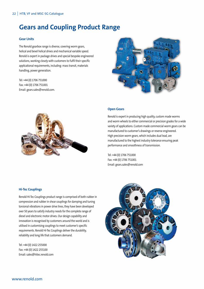
Gears and Coupling Product Range
www.renold.com
The Renold gearbox range is diverse, coveringworm gears,
helical and bevel helical drives andmechanical variable speed.
Renold is expert in package drives and special bespoke engineered
solutions, working closely with customers to fulfil their specific
applicational requirements, including:mass transit, materials
handling, power generation.
Tel: +44 (0) 1706 751000
Fax: +44 (0) 1706 751001
Email: [email protected].
Gear Units
Renold is expert in producing high quality, custommadeworms
andwormwheels to either commercial or precision grades for awide
variety of applications. Custommade commercial worm gears can be
manufactured to customer’s drawings or reverse engineered.
High precisionworm gears, which includes dual lead, are
manufactured to the highest industry tolerance ensuring peak
performance and smoothness of transmission.
Tel: +44 (0) 1706 751000
Fax: +44 (0) 1706 751001
Email: [email protected]
OpenGears
Renold Hi-Tec Couplings product range is comprised of both rubber in
compression and rubber in shear couplings for damping and tuning
torsional vibrations in power drive lines, they have been developed
over 50 years to satisfy industry needs for the complete range of
diesel and electronicmotor drives. Our design capability and
innovation is recognised by customers around theworld and is
utilised in customising couplings tomeet customer’s specific
requirements. Renold Hi-Tec Couplings deliver the durability,
reliability and long life that customers demand.
Tel: +44 (0) 1422 255000
Fax: +44 (0) 1422 255100
Email: [email protected]
Hi-Tec Couplings

HTB, VF and MSG-SG Marine Catalogue I 23
www.renold.com
Gears and Coupling Product Range
Renold Couplingsmanufactures specialist and industrial couplings.
These include, Hydrastart fluid couplings, Gearflex gear couplings,
Renoldflex torsionally rigid couplings and elastomeric couplings that
include the Pinflex and Crownpin pin and bush couplings and the
Discflex coupling range. Popular industrial products include the
Spiderflex, Tyreflex and Chainflex couplings.
This wide and varied portfolio offers torque transmission capability
from 107Nm through to 4,747,000Nm. Renold Couplings has the
coupling solution for awide range of demanding applications.
Tel: +44 (0) 2920 792737
Fax: +44 (0) 2920 793004
Email: [email protected]
Couplings
The Renold range of Freewheel Clutches feature both Sprag and Roller
Ramp technology. Sprag Clutches are used in awide range of safety
critical applications. Typical examples of these are safety backstops on
inclined bucket conveyor systems and holdbacks that can protect
riders on some of theworldsmost thrilling roller coasters.
The Trapped Roller range (roller ramp technology), are directly
interchangeablewith freewheels available in themarket today. These
high quality freewheel products deliver Backstopping, Overrunning
and Indexing capabilities for awide range of customer applications.
Tel: +44 (0) 2920 792737
Fax: +44 (0) 2920 793004
Email: [email protected]
Freewheel Clutches
Renoldmill products consist of Gear spindles, Universal joint drive
shafts and Gear Couplings. Renold Gear Spindles are designed to
meet specific customer and application needs.Material, heat
treatment, and gear geometry are selected for the specific
requirements of each application. Three dimensionalmodeling and
Finite Element Analysis (FEA) are used to further enhance the design
process and to assure the best possible design solution.
Universal Joint drive shafts are available in both English andMetric
sizes and offer a broad range of options and sizes up to and including
1.5meter diameter.
Gear Couplings are offered in sizes ranging fromAGMA size 1 through
size 30 providing torque capabilities from 12,700 in-lb (1435Nm) up
to 51,000,000 in-lb (5,762,224Nm).
Tel: +1 716 326 3121
Fax: +1 716 326 8229
Email: [email protected]
AjaxMill Products

Superior Coupling Technology
AUSTRIAViennaTel: 00 43 1 3303484 0Fax: 00 43 1 3303484 5email: [email protected]
AUSTRALIAMelbourne (Victoria)Tel. 00 61 (0) 3 9262 3333Fax. 00 61 (0) 3 9561 8561email: [email protected]
BELGIUMNivellesTel. 00 32 67493740Fax. 00 32 67442534email: [email protected]
CANADAVille LaSalleTel: 00 1 (800) 265-9970Fax: 00 1 (800) 661-6118email: [email protected]
CHINAShanghaiTel. 00 86 21 5046 2696Fax. 00 86 21 5046 2695email: [email protected]
CZECH REPUBLICZlinTel. 0042 (0) 606 727 811Fax. 0042 (0) 577m240 324email: [email protected]
FINLANDVantaaTel. 00 358 92532 3100Fax. 00 358 92532 3177email: [email protected]
FRANCESeclinTel. 00 33 (0) 320 16 29 29Fax. 00 33 (0) 320 16 29 00email: [email protected]
GERMANYMechernichTel. 00 49 2256 959074Fax. 00 49 2256 959169email: [email protected]
GREECEPiraeusTel. 00 30 1 4170266Fax. 00 30 1 4170253email: [email protected]
ITALYMilanTel. 00 39 02 67861Fax. 00 39 02 6698 1669email: [email protected]
JAPANTokyoTel. 00 81 6244 0172Fax. 00 81 6244 0218email: [email protected]
KOREASeoulTel. 00 822 63403400Fax. 00 822 6340 3409email: [email protected]
MALAYSIASelangorTel. 00 603 5191 9880Fax. 00 603 5191 9881/6881email: [email protected]
NETHERLANDSBredaTel. 00 31 7652 06114Fax. 00 31 7652 07122email: [email protected]
NEWZEALANDAucklandTel. 00 64 (0) 828 5018Fax. 00 64 (0) 828 5019email: [email protected]
SINGAPORESingaporeTel. 00 65 6760 2422Fax. 00 65 6760 1507email: [email protected]
SOUTHAFRICABenoniTel. 00 27 (0) 11 845 1535Fax. 00 27 (0) 11 421 9289email: [email protected]
SPAINBarcelonaTel. 00 34 (93) 638 0558Fax. 00 34 (93) 638 0737email: [email protected]
UKRenold Hi-Tec CouplingsTel +44 (0)1422 255000Fax +44 (0)1422 255100email: [email protected]
USAWestfield NYTel. 00 1 716 326 3121Fax. 00 1 716 326 8229email: [email protected]
E-MAILemail: [email protected]
Renold has representation on everycontinent. For other country distributorsplease contact Renold UK or visit theRenoldwebsite.
Whilst all reasonable care in compilingthe information contained in thisbrochure is taken, no responsibility isaccepted for printing errors.All information contained in thisbrochure is subject to change after thedate of publication.
E4-05-157 rev 100HTB/VF/MSC-SG Cat English/0511A Business of Renold Power Transmission Ltd.
www.renold.com