document
DESCRIPTION
http://www.wexoe.dk/fileadmin/produktchefer/dokumentation/hager/TH210_Product_information_manual_GB.pdfTRANSCRIPT
6T7519a1
TH210
Manual
Product designation
IP/KNX Router
Product reference
Introduction .................................................................... 2
Configuration recommendations for the IP/KNX RouterTH210 ............................................................................. 2
Device features ............................................................2Bus parameters ........................................................... 2Network settings ......................................................... 3
Automatic IP address assignment by DHCP service .................................................................................. 4Manual IP address assignment ................................4Example ................................................................... 4
IP/KNX Router TH210 application examples ............... 6IP/KNX Router TH210 as coupler between installations ..................................................................6IP/KNX Router TH210 as area coupler ....................... 7IP/KNX Router TH210 as line coupler .........................8Building Control via KNX Control Center .................... 9Building Control via OPC Server ...............................10Building Contriol via DSL Router with DynDNS ........11Building Control via Web-Browser ............................ 12
How to configure Internet Information Server (IIS) asweb server ..............................................................12
Introduction to the Internet Protocol (IP) ....................14Introduction ............................................................... 14Structure of an IP Network ...................................... 14
Addressing ................................................................... 15IP Address ................................................................. 15Subnet and subnet mask .......................................... 15Standard Gateway .....................................................15IP Multicast Address ................................................. 15
Glossary ........................................................................16
Table of Contents
Line coupler
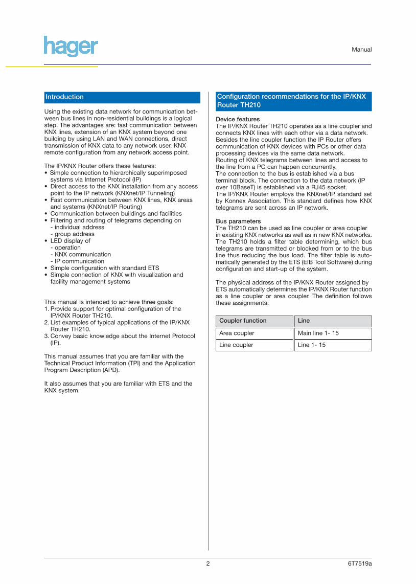
Device featuresThe IP/KNX Router TH210 operates as a line coupler andconnects KNX lines with each other via a data network.Besides the line coupler function the IP Router offerscommunication of KNX devices with PCs or other dataprocessing devices via the same data network.Routing of KNX telegrams between lines and access tothe line from a PC can happen concurrently.The connection to the bus is established via a busterminal block. The connection to the data network (IPover 10BaseT) is established via a RJ45 socket.The IP/KNX Router employs the KNXnet/IP standard setby Konnex Association. This standard defines how KNXtelegrams are sent across an IP network.
Bus parametersThe TH210 can be used as line coupler or area couplerin existing KNX networks as well as in new KNX networks.The TH210 holds a filter table determining, which bustelegrams are transmitted or blocked from or to the busline thus reducing the bus load. The filter table is auto-matically generated by the ETS (EIB Tool Software) duringconfiguration and start-up of the system.
The physical address of the IP/KNX Router assigned byETS automatically determines the IP/KNX Router functionas a line coupler or area coupler. The definition followsthese assignments:
6T7519a2
Using the existing data network for communication bet-ween bus lines in non-residential buildings is a logicalstep. The advantages are: fast communication betweenKNX lines, extension of an KNX system beyond onebuilding by using LAN and WAN connections, directtransmission of KNX data to any network user, KNXremote configuration from any network access point.
The IP/KNX Router offers these features:• Simple connection to hierarchically superimposed
systems via Internet Protocol (IP)• Direct access to the KNX installation from any access
point to the IP network (KNXnet/IP Tunneling)• Fast communication between KNX lines, KNX areas
and systems (KNXnet/IP Routing)• Communication between buildings and facilities• Filtering and routing of telegrams depending on
- individual address- group address
• LED display of- operation- KNX communication- IP communication
• Simple configuration with standard ETS• Simple connection of KNX with visualization and
facility management systems
This manual is intended to achieve three goals:1. Provide support for optimal configuration of the
IP/KNX Router TH210.2. List examples of typical applications of the IP/KNX
Router TH210.3. Convey basic knowledge about the Internet Protocol
(IP).
This manual assumes that you are familiar with theTechnical Product Information (TPI) and the ApplicationProgram Description (APD).
It also assumes that you are familiar with ETS and theKNX system.
Area coupler
Coupler function
Line 1- 15
Main line 1- 15
Line
Introduction Configuration recommendations for the IP/KNXRouter TH210
Manual

5/5/1
4/1/15/2/1
4/1/1
4/1/1
Device3.3.1
Device3.3.2
IP RouterTH2103.3.0
IP Network
5/5/1
Device1.1.1
Device1.1.2
5/5/1
IP RouterTH2101.1.0
KNX
5/5/1
4/1/1
4/1/1
Main Line 2
IP RouterTH2102.0.0
Device2.1.1
Device2.2.1
Device2.1.2
Device2.2.2
Line Coupler
2.1.0
Line Coupler
2.2.0
IP
6T7519a3
NoteWhen assigning the physical address take care thatIP/KNX Router and line couplers receive the topological-ly correct physical address (Fig. 1, IP/KNX Router as areacoupler and line coupler).Adhere to these rules:
Rule 1:In general an IP/KNX Router TH210 is used as a linecoupler or an area coupler. The physical address hasthe format x.y.0, with x=1…15, y=1…15.
Rule 2:If an IP/KNX Router TH210 is applied as an area couplerwith the physical address x.0.0 then no other IP/KNXRouter with the line coupler address x.y.0 (y=1…15)shall be placed topologically “below“ this IP/KNX Router(Fig. 2, IP/KNX Router TH210 as area coupler).
Rulel 3:If an IP/KNX Router TH210 is applied as a line coupler(e.g. with physical address 1.2.0) then no other IP/KNXRouter TH210 shall be used with a superior areacoupler address (e.g. 1.0.0) in this installation (Fig. 3,IP/KNX Router TH210 as line coupler).
Figure 2. IP/KNX Router TH210 as area coupler
Manual
Figure 1. IP/KNX Router TH210 as area and line coupler
6/3/1
4/1/15/2/1
4/1/1
4/1/1
4/1/1
4/1/1
5/2/1 6/3/1
5/2/1 5/2/1
5/2/1
4/1/1 4/1/1
IP Network IP Network
Main Line 2
IP RouterTH2102.0.0
Main Line 1
IP RouterTH2101.0.0
Device1.1.1
Device1.2.1
Device1.3.1
Device2.1.1
Device2.2.1
Device1.1.2
Device1.2.2
Device1.3.2
Device2.1.2
Device2.2.2
Line Coupler
1.2.0
Line Coupler
1.3.0
Line Coupler
2.1.0
Line Coupler
2.2.0
4/1/1
Line Coupler
1.1.0
6/3/1
4/1/15/2/1
4/1/1
4/1/1
4/1/1
5/2/1 6/3/1
5/2/1 5/2/1
5/2/1
Device1.2.1
Device1.3.1
Device2.1.1
Device2.2.1
Device1.2.2
Device1.3.2
Device2.1.2
Device2.2.2
IP Router TH210r1.2.0
IP Router TH2101.3.0
IP Router TH2102.1.0
IP Router TH2102.2.0
IP Network
4/1/1
Device1.1.1
Device1.1.2
4/1/1
IP Router TH2101.1.0
KNX
IP
Figure 3. IP/KNX Router TH210 as line coupler
Network settingsThe IP/KNX Router TH210 requires an IP address to communicate on the IP network. This IP address can beassigned manually using ETS or automatically by aDHCP service.When can an IP address be assigned by a DHCP service?IP address assignment via DHCP is typically activatedwhen the network is managed by a network administra-tor.Configuration of the DHCP server may require the MACaddress, which is printed on the device.The DHCP service is employed by newer LAN modemsand DSL routers. These devices support DHCP: SIEMENS SE505 DSL RouterWhen should the IP address be set manually ?The IP address has to be set manually if no DHCP service is present in the network.Networked Building Controls are a part of the buildinginfrastructure. It’s structure is unchanged for longer periods, which lends itself to reserving a fixed IP addressin the network.
6T7519a4
Manual
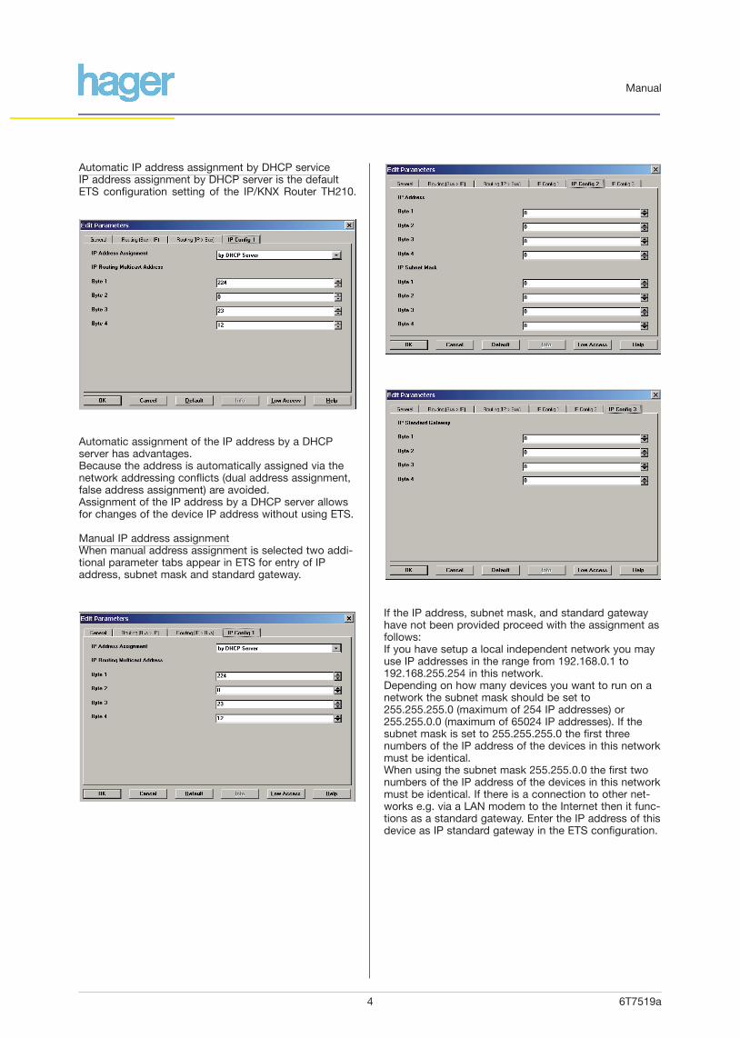
Automatic IP address assignment by DHCP serviceIP address assignment by DHCP server is the defaultETS configuration setting of the IP/KNX Router TH210.
Automatic assignment of the IP address by a DHCPserver has advantages.Because the address is automatically assigned via thenetwork addressing conflicts (dual address assignment,false address assignment) are avoided.Assignment of the IP address by a DHCP server allowsfor changes of the device IP address without using ETS.
Manual IP address assignmentWhen manual address assignment is selected two addi-tional parameter tabs appear in ETS for entry of IPaddress, subnet mask and standard gateway.
If the IP address, subnet mask, and standard gatewayhave not been provided proceed with the assignment asfollows:If you have setup a local independent network you mayuse IP addresses in the range from 192.168.0.1 to192.168.255.254 in this network.Depending on how many devices you want to run on anetwork the subnet mask should be set to255.255.255.0 (maximum of 254 IP addresses) or255.255.0.0 (maximum of 65024 IP addresses). If thesubnet mask is set to 255.255.255.0 the first three numbers of the IP address of the devices in this networkmust be identical.When using the subnet mask 255.255.0.0 the first twonumbers of the IP address of the devices in this networkmust be identical. If there is a connection to other net-works e.g. via a LAN modem to the Internet then it func-tions as a standard gateway. Enter the IP address of thisdevice as IP standard gateway in the ETS configuration.
6T7519a5
Manual
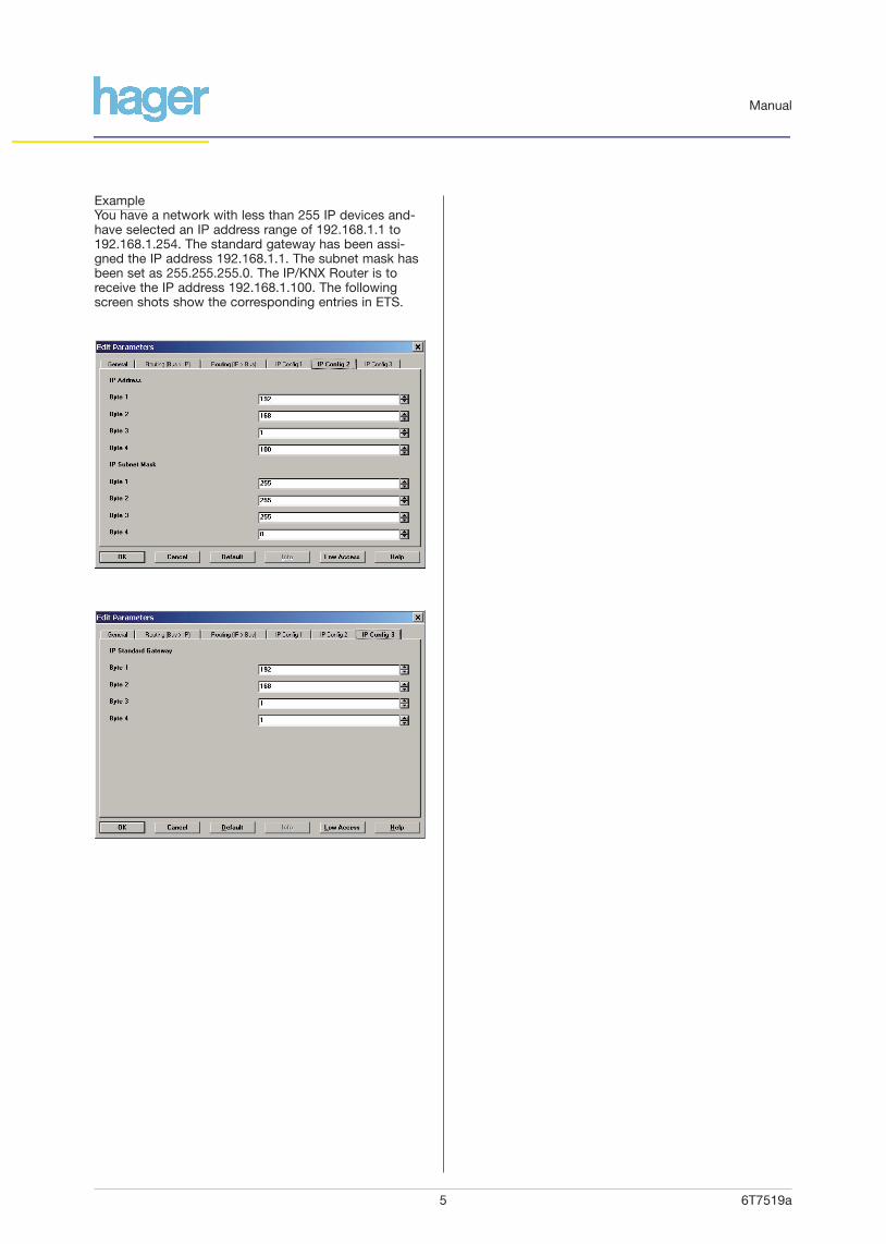
ExampleYou have a network with less than 255 IP devices and-have selected an IP address range of 192.168.1.1 to192.168.1.254. The standard gateway has been assi-gned the IP address 192.168.1.1. The subnet mask hasbeen set as 255.255.255.0. The IP/KNX Router is toreceive the IP address 192.168.1.100. The followingscreen shots show the corresponding entries in ETS.
6T7519a6
Manual
IP/KNX Router TH210 application examples
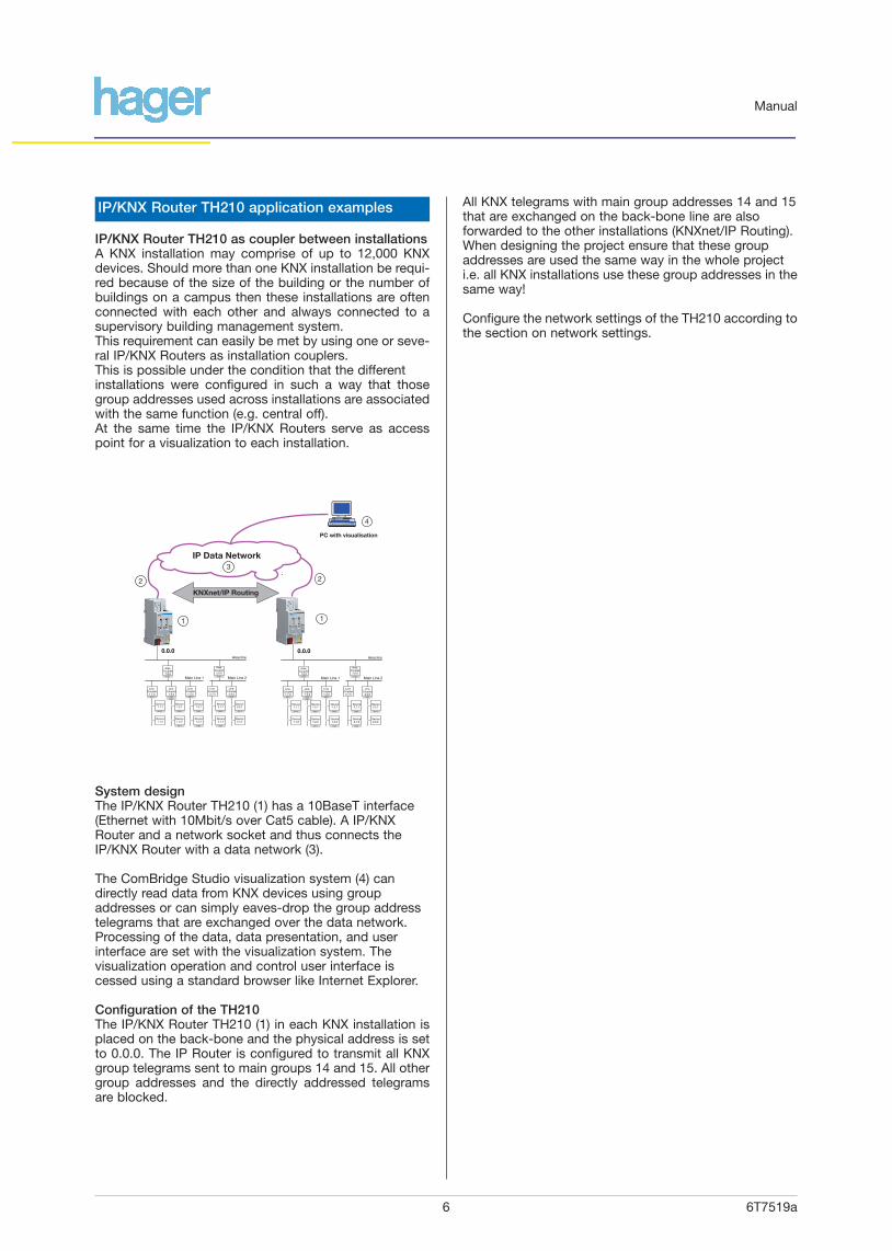
IP/KNX Router TH210 as coupler between installationsA KNX installation may comprise of up to 12,000 KNXdevices. Should more than one KNX installation be requi-red because of the size of the building or the number ofbuildings on a campus then these installations are oftenconnected with each other and always connected to asupervisory building management system.This requirement can easily be met by using one or seve-ral IP/KNX Routers as installation couplers.This is possible under the condition that the differentinstallations were configured in such a way that thosegroup addresses used across installations are associatedwith the same function (e.g. central off).At the same time the IP/KNX Routers serve as accesspoint for a visualization to each installation.
System designThe IP/KNX Router TH210 (1) has a 10BaseT interface(Ethernet with 10Mbit/s over Cat5 cable). A IP/KNXRouter and a network socket and thus connects theIP/KNX Router with a data network (3).
The ComBridge Studio visualization system (4) candirectly read data from KNX devices using groupaddresses or can simply eaves-drop the group addresstelegrams that are exchanged over the data network.Processing of the data, data presentation, and userinterface are set with the visualization system. Thevisualization operation and control user interface is cessed using a standard browser like Internet Explorer.
Configuration of the TH210The IP/KNX Router TH210 (1) in each KNX installation isplaced on the back-bone and the physical address is setto 0.0.0. The IP Router is configured to transmit all KNXgroup telegrams sent to main groups 14 and 15. All othergroup addresses and the directly addressed telegramsare blocked.
All KNX telegrams with main group addresses 14 and 15that are exchanged on the back-bone line are also forwarded to the other installations (KNXnet/IP Routing).When designing the project ensure that these groupaddresses are used the same way in the whole projecti.e. all KNX installations use these group addresses in thesame way!
Configure the network settings of the TH210 according tothe section on network settings.
6/3/1
4/1/15/2/1
4/1/1
4/1/1
4/1/1
4/1/1
5/2/1 6/3/1
5/2/1 5/2/1
5/2/1
4/1/1 4/1/1
Area line
0.0.0
Main Line 2
Area Coupler
2.0.0
Main Line 1
Area Coupler
1.0.0
Device1.1.1
Device1.2.1
Device1.3.1
Device2.1.1
Device2.2.1
Device1.1.2
Device1.2.2
Device1.3.2
Device2.1.2
Device2.2.2
Line Coupler
1.2.0
Line Coupler
1.3.0
Line Coupler
2.1.0
Line Coupler
2.2.04/1/1
Line Coupler
1.1.0
6/3/1
4/1/15/2/1
4/1/1
4/1/1
4/1/1
4/1/1
5/2/1 6/3/1
5/2/1 5/2/1
5/2/1
4/1/1 4/1/1
Area line
Main Line 2
Area Coupler
2.0.0
Main Line 1
Area Coupler
1.0.0
Device1.1.1
Device1.2.1
Device1.3.1
Device2.1.1
Device2.2.1
Device1.1.2
Device1.2.2
Device1.3.2
Device2.1.2
Device2.2.2
Line Coupler
1.2.0
Line Coupler
1.3.0
Line Coupler
2.1.0
Line Coupler
2.2.04/1/1
Line Coupler
1.1.0
0.0.0
4
11
2 2
KNXnet/IP Routing
PC with visualisation
3
IP Data Network
6T7519a7
Manual
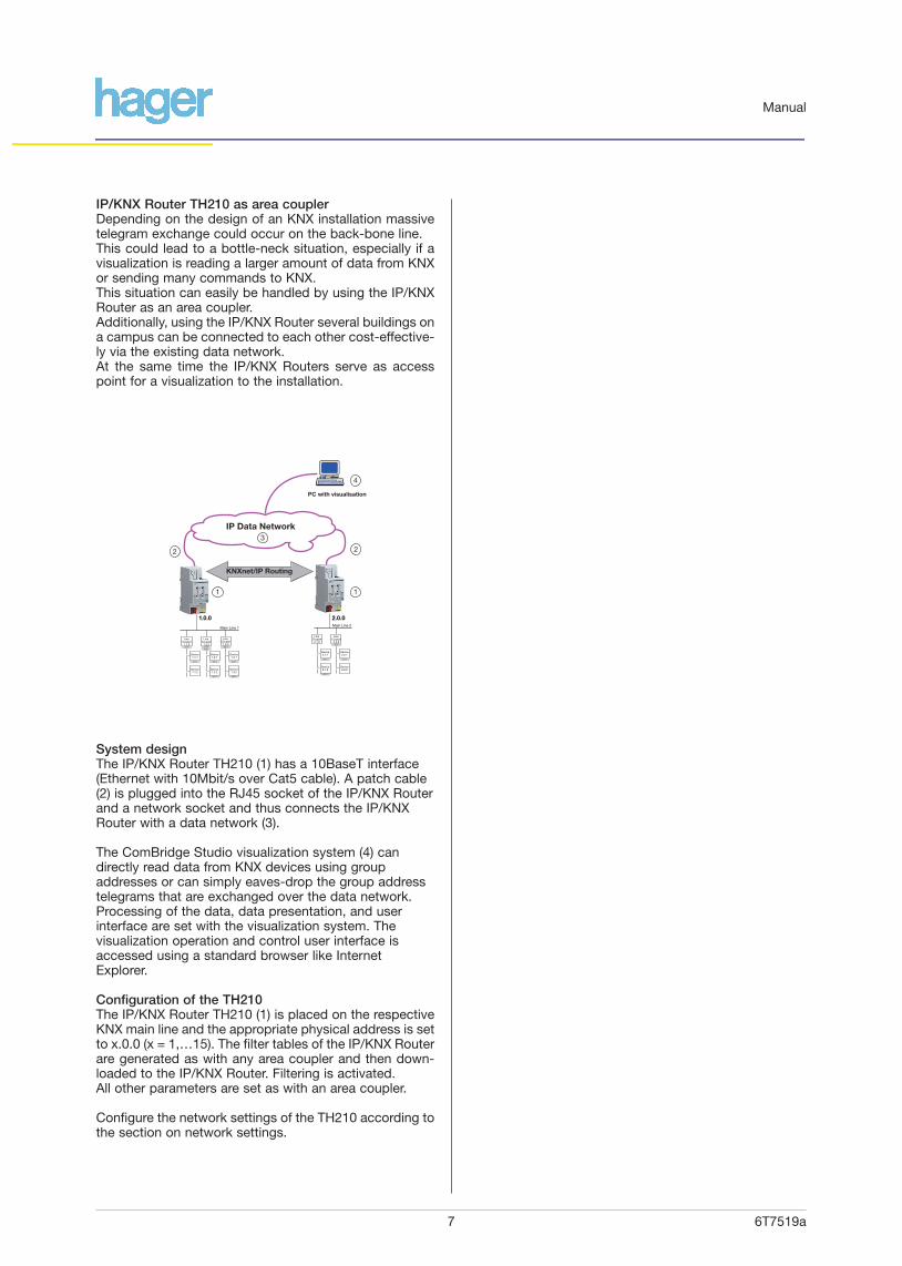
IP/KNX Router TH210 as area couplerDepending on the design of an KNX installation massivetelegram exchange could occur on the back-bone line.This could lead to a bottle-neck situation, especially if avisualization is reading a larger amount of data from KNXor sending many commands to KNX.This situation can easily be handled by using the IP/KNXRouter as an area coupler.Additionally, using the IP/KNX Router several buildings ona campus can be connected to each other cost-effective-ly via the existing data network.At the same time the IP/KNX Routers serve as accesspoint for a visualization to the installation.
System designThe IP/KNX Router TH210 (1) has a 10BaseT interface(Ethernet with 10Mbit/s over Cat5 cable). A patch cable(2) is plugged into the RJ45 socket of the IP/KNX Routerand a network socket and thus connects the IP/KNXRouter with a data network (3).
The ComBridge Studio visualization system (4) candirectly read data from KNX devices using groupaddresses or can simply eaves-drop the group addresstelegrams that are exchanged over the data network.Processing of the data, data presentation, and userinterface are set with the visualization system. Thevisualization operation and control user interface isaccessed using a standard browser like InternetExplorer.
Configuration of the TH210The IP/KNX Router TH210 (1) is placed on the respectiveKNX main line and the appropriate physical address is setto x.0.0 (x = 1,…15). The filter tables of the IP/KNX Routerare generated as with any area coupler and then down-loaded to the IP/KNX Router. Filtering is activated. All other parameters are set as with an area coupler.
Configure the network settings of the TH210 according tothe section on network settings.
4
PC with visualisation
11
2 2
KNXnet/IP Routing
4/1/15/2/1
4/1/1
4/1/1 5/2/1
5/2/1 5/2/1
5/2/1
1.0.0 2.0.0Main Line 1
Device1.1.1
Device1.2.1
Device1.3.1
Device1.1.2
Device1.2.2
Device1.3.2
Line Coupler
1.2.0
Line Coupler
1.3.04/1/1
Line Coupler
1.1.0
6/3/1
4/1/1
4/1/1
6/3/1
Main Line 2
Device2.1.1
Device2.2.1
Device2.1.2
Device2.2.2
Line Coupler
2.1.0
Line Coupler
2.2.0
3
IP Data Network

6T7519a8
Manual
IP/KNX Router TH210 as line couplerSimple system design and fast communication betweenKNX lines can be achieved with the IP/KNX Router TH210when used as a line coupler.Depending on the size of the project the direct connectionof each line to a data network can accelerate communica-tion up to 200 times compared to the conventional systemdesign.When using up to three KNX repeaters below the IP/KNXRouter up to 250 KNX devices can be deployed per line.This enables installations with up to 48,000 KNX devices.Using the existing data network the IP/KNX Router makesconnecting the KNX controls of several buildings on acampus easy and cost-effective.At the same time the IP/KNX Routers serve as accesspoint for a visualization to the installation.
System designThe IP/KNX Router TH210 (1) has a 10BaseT interface(Ethernet with 10Mbit/s over Cat5 cable). A patch cable(2) is plugged into the RJ45 socket of the IP/KNX Routerand a network socket and thus connects the IP/KNXRouter with a data network (3).
The ComBridge Studio visualization system (4) candirectly read data from KNX devices using groupaddresses or can simply eaves-drop the group addresstelegrams that are exchanged over the data network.Processing of the data, data presentation, and user inter-face are set with the visualization system. The visualiza-tion operation and control user interface is accessedusing a standard browser like Internet Explorer.
Configuration of the TH210The IP/KNX Router TH210 (1) is placed as an KNX linecoupler and the appropriate physical address is set tox.y.0 (x = 1,…15; y = 1…15). The filter tables of theIP/KNX Router are generated as with any line coupler andthen downloaded to the IP/KNX Router. Filtering is activated. All other parameters are set as with a line coupler.
Configure the network settings of the TH210 according tothe section on network settings.
4
PC with visualisation
1
2
2
1 1
4/1/1
4/1/1 5/2/1
5/2/1 5/2/1
Device1.1.1
Device1.2.1
Device1.3.1
Device1.1.2
Device1.2.2
Device1.3.2
1.1.0 1.2.0 1.3.0
KNXnet/IP Routing
3
IP Data Network

6T7519a9
Manual
Building Control via KNX Control CenterModern visualization systems like ComBridge Studio usenetwork communication based on the Internet Protocol(IP). With the KNXnet/IP protocol integration of KNX intothis network communication is straightforward.It allows for simple connection of KNX installations in dif-ferent buildings or locations with a central visualization orbuilding management system.Data transmitted to the visualization system can be collec-ted, archived, and processed. Modern visualization systemenable user interaction via a web browser interface,effectively making every web browser equipped PC anoperator station. If access to the data network exists anyPC world-wide could become a control interface to theKNX system.For the users in the building such a visualization solutionallows them to take direct control of their immediate workenvironment by changing lighting, shading and heatingsettings from their PC.
System designThe IP/KNX Router TH210 (1) has a 10BaseT interface(Ethernet with 10Mbit/s over Cat5 cable). A patch cable(2) is plugged into the RJ45 socket of the IP/KNX Routerand a network socket and thus connects the IP/KNXRouter with a data network (3).
The IP/KNX Router is primarily used for connection ofKNX areas or lines with each other.
At the same time the IP/KNX Router TH210 offers accessto an KNX installation via an IP network from a PC with avisualization (4). One IP/KNX Router may be used asvisualization interface to an KNX installation. It could alsobe that several IP/KNX Routers are used as area or linecouplers. In this case the visualization establishes an IPconnection to with all IP/KNX Routers and/or eaves-drops on the KNX telegrams exchanged between IP/KNXRouters.
The ComBridge Studio visualization system (4) is installedon a PC, which is connected to the IP network.The visualization can directly read data from KNX devicesusing group addresses or can simply eaves-drop thegroup address telegrams that are exchanged over thedata network. Processing of the data, data presentation,and user interface are configured in a simple text file.
A KNX Control Center presents the current values andstates as a table in a window that also provides forcontrol of the data points.
Configuration of the TH210If the IP/KNX Router and the visualization server (4) areconnected to each other via an independently operatinglocal network, the IP address of the IP/KNX Router shouldbe set using ETS. To make configuration easy the firstthree numbers of the IP address of IP/KNX Router andvisualization server should be identical. The subnet maskof the IP/KNX Router must be identical to that of thevisualization server.
Beyond these recommendations, configure the networksettings of the TH210 according to the section on network settings.
6/3/1
4/1/15/2/1
4/1/1
4/1/1
4/1/1
4/1/1
5/2/1 6/3/1
5/2/1 5/2/1
5/2/1
4/1/1 4/1/1
Area line
Main Line 2
Area Coupler
2.0.0
Main Line 1
Area Coupler
1.0.0
Device1.1.1
Device1.2.1
Device1.3.1
Device2.1.1
Device2.2.1
Device1.1.2
Device1.2.2
Device1.3.2
Device2.1.2
Device2.2.2
Line Coupler
1.2.0
Line Coupler
1.3.0
Line Coupler
2.1.0
Line Coupler
2.2.04/1/1
Line Coupler
1.1.0
4
PC with visualisation1
23
IP Data Network
6T7519a10
Manual
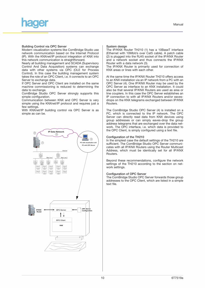
Building Control via OPC ServerModern visualization systems like ComBridge Studio usenetwork communication based on the Internet Protocol(IP). With the KNXnet/IP protocol integration of KNX intothis network communication is straightforward.Nearly all building management and SCADA (SupervisoryControl And Data Acquisition) systems can exchangedata with other systems via OPC (OLE for ProcessControl). In this case the building management systemtakes the role of an OPC Client, i.e. it connects to an OPCServer to exchange data.If OPC Server and OPC Client are installed on the samemachine commissioning is reduced to determining thedata to exchange.ComBridge Studio OPC Server strongly supports thissimple configuration.Communication between KNX and OPC Server is verysimple using the KNXnet/IP protocol and requires just afew settings.With KNXnet/IP building control via OPC Server is assimple as can be.
System designThe IP/KNX Router TH210 (1) has a 10BaseT interface(Ethernet with 10Mbit/s over Cat5 cable). A patch cable(2) is plugged into the RJ45 socket of the IP/KNX Routerand a network socket and thus connects the IP/KNXRouter with a data network (3). The IP/KNX Router is primarily used for connection ofKNX areas or lines with each other.
At the same time the IP/KNX Router TH210 offers accessto an KNX installation via an IP network from a PC with anOPC Server (4). One IP/KNX Router may be used by theOPC Server as interface to an KNX installation. It couldalso be that several IP/KNX Routers are used as area orline couplers. In this case the OPC Server establishes anIP connection to with all IP/KNX Routers and/or eaves-drops on the KNX telegrams exchanged between IP/KNXRouters.
The ComBridge Studio OPC Server (4) is installed on aPC, which is connected to the IP network. The OPCServer can directly read data from KNX devices usinggroup addresses or can simply eaves-drop the groupaddress telegrams that are exchanged over the data net-work. The OPC interface, i.e. which data is provided tothe OPC Client, is simply configured using a text file.
Configuration of the TH210In the simplest case the default settings of the TH210 aresufficient. The ComBridge Studio OPC Server communi-cates with all IP/KNX Routers using the Router MulticastAddress, which must be identically set for all IP/KNXRouters.
Beyond these recommendations, configure the networksettings of the TH210 according to the section on net-work settings.
Configuration of OPC ServerThe ComBridge Studio OPC Server forwards those groupaddresses to the OPC Client, which are listed in a simpletext file.
OPC Server
OPC Client
KNX
IP/KNX Router
6/3/1
4/1/15/2/1
4/1/1
4/1/1
4/1/1
4/1/1
5/2/1 6/3/1
5/2/1 5/2/1
5/2/1
4/1/1 4/1/1
Area line
Main Line 2
Area Coupler
2.0.0
Main Line 1
Area Coupler
1.0.0
Device1.1.1
Device1.2.1
Device1.3.1
Device2.1.1
Device2.2.1
Device1.1.2
Device1.2.2
Device1.3.2
Device2.1.2
Device2.2.2
Line Coupler
1.2.0
Line Coupler
1.3.0
Line Coupler
2.1.0
Line Coupler
2.2.04/1/1
Line Coupler
1.1.0
4
PC with visualisation soft
PC with OPC Server
3
1
2IP Data Network
OPC ServerConfiguration
6T7519a11
Manual
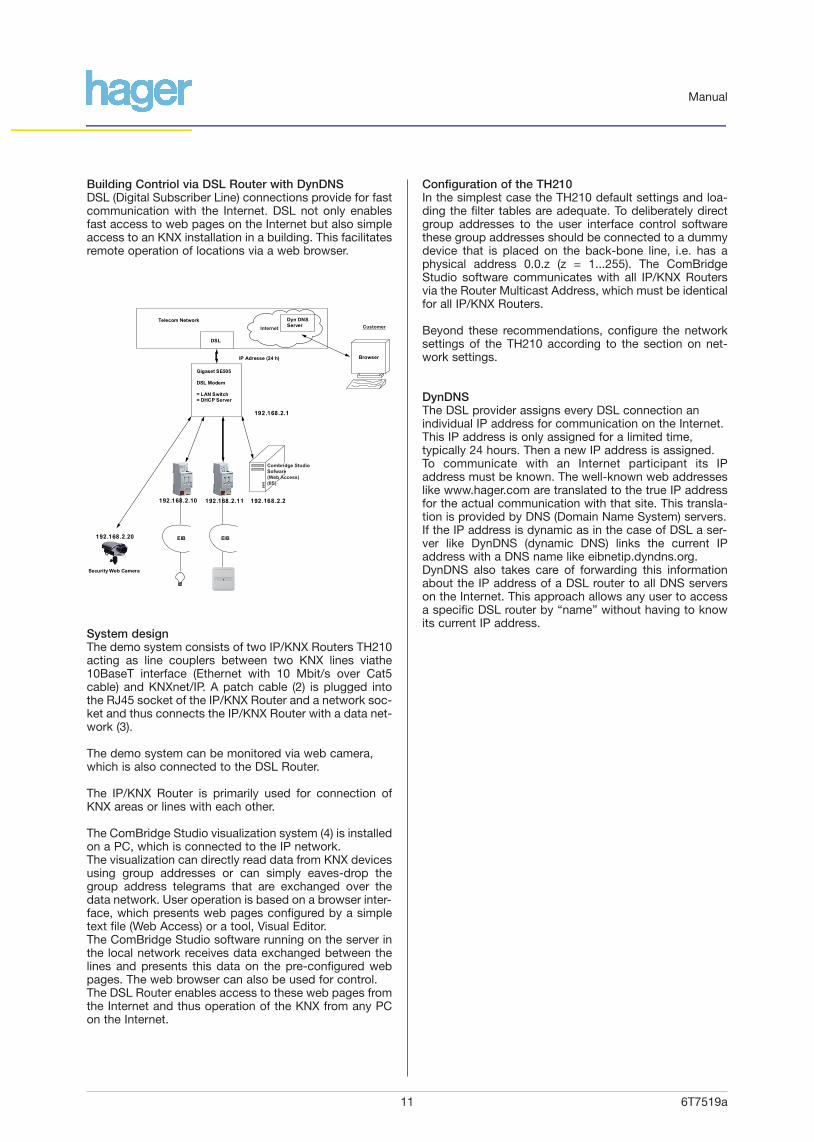
Building Contriol via DSL Router with DynDNSDSL (Digital Subscriber Line) connections provide for fastcommunication with the Internet. DSL not only enablesfast access to web pages on the Internet but also simpleaccess to an KNX installation in a building. This facilitatesremote operation of locations via a web browser.
System designThe demo system consists of two IP/KNX Routers TH210acting as line couplers between two KNX lines viathe10BaseT interface (Ethernet with 10 Mbit/s over Cat5cable) and KNXnet/IP. A patch cable (2) is plugged intothe RJ45 socket of the IP/KNX Router and a network soc-ket and thus connects the IP/KNX Router with a data net-work (3).
The demo system can be monitored via web camera,which is also connected to the DSL Router.
The IP/KNX Router is primarily used for connection ofKNX areas or lines with each other.
The ComBridge Studio visualization system (4) is installedon a PC, which is connected to the IP network.The visualization can directly read data from KNX devicesusing group addresses or can simply eaves-drop thegroup address telegrams that are exchanged over thedata network. User operation is based on a browser inter-face, which presents web pages configured by a simpletext file (Web Access) or a tool, Visual Editor.The ComBridge Studio software running on the server inthe local network receives data exchanged between thelines and presents this data on the pre-configured webpages. The web browser can also be used for control.The DSL Router enables access to these web pages fromthe Internet and thus operation of the KNX from any PCon the Internet.
Configuration of the TH210In the simplest case the TH210 default settings and loa-ding the filter tables are adequate. To deliberately directgroup addresses to the user interface control softwarethese group addresses should be connected to a dummydevice that is placed on the back-bone line, i.e. has aphysical address 0.0.z (z = 1...255). The ComBridgeStudio software communicates with all IP/KNX Routersvia the Router Multicast Address, which must be identicalfor all IP/KNX Routers.
Beyond these recommendations, configure the networksettings of the TH210 according to the section on net-work settings.
DynDNSThe DSL provider assigns every DSL connection an individual IP address for communication on the Internet.This IP address is only assigned for a limited time, typically 24 hours. Then a new IP address is assigned. To communicate with an Internet participant its IPaddress must be known. The well-known web addresseslike www.hager.com are translated to the true IP addressfor the actual communication with that site. This transla-tion is provided by DNS (Domain Name System) servers.If the IP address is dynamic as in the case of DSL a ser-ver like DynDNS (dynamic DNS) links the current IPaddress with a DNS name like eibnetip.dyndns.org.DynDNS also takes care of forwarding this informationabout the IP address of a DSL router to all DNS serverson the Internet. This approach allows any user to accessa specific DSL router by “name” without having to knowits current IP address.
DSL
Telecom Network
Browser
Gigaset SE505
DSL Modem
= LAN Switch= DHCP Server
IP Adresse (24 h)
192.168.2.1
192.168.2.10 192.168.2.11 192.168.2.2
EIB192.168.2.20
Security Web Camera
EIB
Dyn DNS Server
Combridge StudioSofware(Web Access)(IIS)
CustomerInternet
6T7519a12
Manual
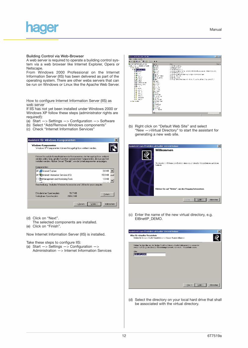
Building Control via Web-BrowserA web server is required to operate a building control sys-tem via a web browser like Internet Explorer, Opera orNetscape.From Windows 2000 Professional on the InternetInformation Server (IIS) has been delivered as part of theoperating system. There are other webs servers that canbe run on Windows or Linux like the Apache Web Server.
How to configure Internet Information Server (IIS) asweb serverIf IIS has not yet been installed under Windows 2000 orWindows XP follow these steps (administrator rights arerequired!):(a) Start —> Settings —> Configuration —> Software(b) Select “Add/Remove Windows components”(c) Check “Internet Information Services”
(d) Click on “Next”.The selected components are installed.
(e) Click on “Finish”.
Now Internet Information Server (IIS) is installed.
Take these steps to configure IIS:(a) Start —> Settings —> Configuration —>
Administration —> Internet Information Services
(b) Right click on “Default Web Site” and select “New —>Virtual Directory” to start the assistant for generating a new web site.
(c) Enter the name of the new virtual directory, e.g.EIBnetIP_DEMO.
(d) Select the directory on your local hard drive that shallbe associated with the virtual directory.
6T7519a13
Manual
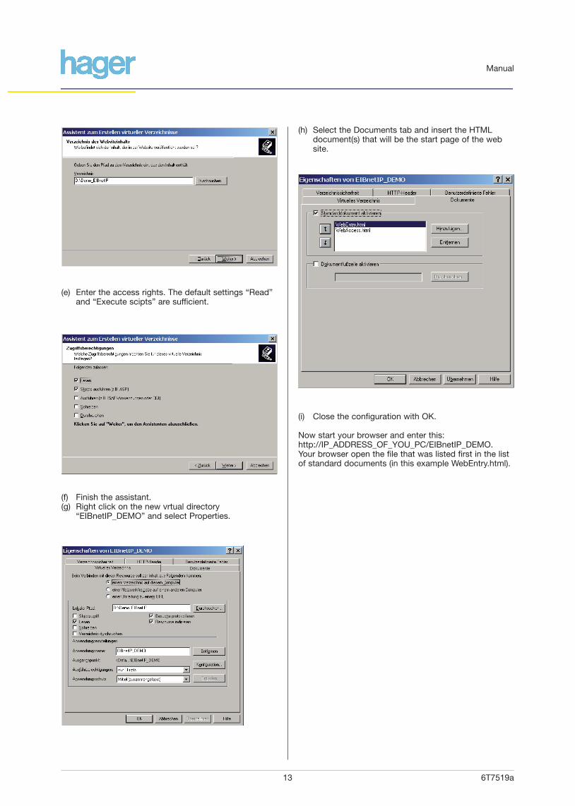
(e) Enter the access rights. The default settings “Read”and “Execute scipts” are sufficient.
(f) Finish the assistant.(g) Right click on the new vrtual directory
“EIBnetIP_DEMO” and select Properties.
(h) Select the Documents tab and insert the HTMLdocument(s) that will be the start page of the website.
(i) Close the configuration with OK.
Now start your browser and enter this:http://IP_ADDRESS_OF_YOU_PC/EIBnetIP_DEMO.Your browser open the file that was listed first in the listof standard documents (in this example WebEntry.html).
6T7519a14
Manual
IntroductionThe connection between three universities in the USAwas the starting point for the Internet in the 1970‘s. Theintention was to facilitate data exchange and cooperationbetween these universities by a network of the networks(= Internet).Originally the Internet was developed as a network bet-ween local networks. These local networks used different,manufacturer-specific network technologies.The Internet Protocol (IP) was designed as the protocolfor communication between networks.With the Ethernet developed by Intel, Xerox and DigitalEquipment a low cost, vendor-independent technologyfor local networks between computers became available.Shortly after the Ethernet was released as vendorinde-pendent technology the Internet Protocol was usedtogether with Ethernet for communication between singlecomputers in a local network.Today Ethernet and the Internet Protocol are the standardin local networks.
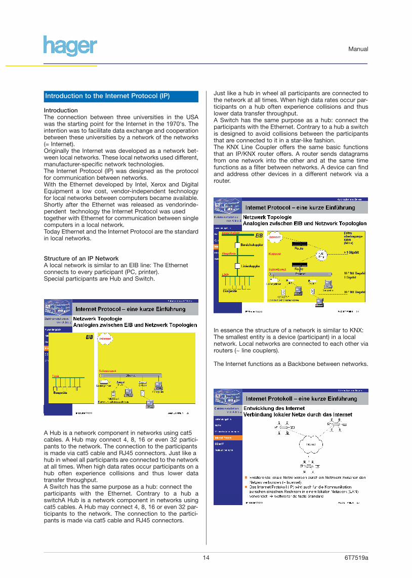
Structure of an IP NetworkA local network is similar to an EIB line: The Ethernetconnects to every participant (PC, printer).Special participants are Hub and Switch.
Introduction to the Internet Protocol (IP)
A Hub is a network component in networks using cat5cables. A Hub may connect 4, 8, 16 or even 32 partici-pants to the network. The connection to the participantsis made via cat5 cable and RJ45 connectors. Just like ahub in wheel all participants are connected to the networkat all times. When high data rates occur participants on ahub often experience collisions and thus lower datatransfer throughput.A Switch has the same purpose as a hub: connect theparticipants with the Ethernet. Contrary to a hub aswitchA Hub is a network component in networks usingcat5 cables. A Hub may connect 4, 8, 16 or even 32 par-ticipants to the network. The connection to the partici-pants is made via cat5 cable and RJ45 connectors.
Just like a hub in wheel all participants are connected tothe network at all times. When high data rates occur par-ticipants on a hub often experience collisions and thuslower data transfer throughput.A Switch has the same purpose as a hub: connect theparticipants with the Ethernet. Contrary to a hub a switch is designed to avoid collisions between the participantsthat are connected to it in a star-like fashion.The KNX Line Coupler offers the same basic functionsthat an IP/KNX router offers. A router sends datagramsfrom one network into the other and at the same timefunctions as a filter between networks. A device can findand address other devices in a different network via arouter.
In essence the structure of a network is similar to KNX:The smallest entity is a device (participant) in a localnetwork. Local networks are connected to each other viarouters (~ line couplers).
The Internet functions as a Backbone between networks.
TH210
TH210
TH210

6T7519a15
Manual
IP AddressIn an IP network every IP device must have a uniqueaddress.This address can be assigned permanently or for a limi-ted time only. A temporary assignment of the IP addressis used when the number of available IP addresses in anetwork is limited. This is the case in most networkstoday. The protocol used for automatic assignment of IPaddresses is DHCP (Dynamic Host ConfigurationProtocol).The IP address notation is xxx.yyy.yyy.xxx, where xxx is anumber between 1 and 254 and yyy is a number between0 and 254.
Subnet and subnet maskSubnets were introduced to optimally use the existingIP address space. Only devices assigned to the samesubnet can communicate directly with each other. Thesubnet mask determines which part of the IP addressrepresents the subnet. This mask takes the formzzz.zzz.zzz.zzz. One of these numbers zzz can take anyof these values: 255, 254, 252, 248, 240, 224, 192, 128,0. The numbers before this number must be 255, all afterit must be 0. Examples of valid subnet masks are:255.255.255.0255.255.255.240255.240.0.0The subnet mask must be entered besides the IPaddress.
Standard GatewayIf an IP device wants to communicate with other IPdevices outside of its subnet this communication is direc-ted through the standard gateway. This standard gatewaycan be e.g. a network router, a DSL modem, or a LANmodem.
IP Multicast AddressAs with EIB group telegrams IP allows to transmit a data-gram to several recipients at the same time. This socalledmulticast form of IP communication requires that senderand recipient are member of the same Multicast Groupand use the same Multicast Address as target address.The Multicast Address 224.0.23.12 has especially beenreserved for EIBnet/IP.For general use in a network multicast addresses in therange from 239.0.0.0 to 239.255.255.255 may be used.
Addressing
6T7519a16
Manual
DHCPAbbreviation of "Dynamic Host Configuration Protocol” – communication protocol for automatic assignment of IP address settings
DNSAbbreviation of "Domain Name Service" – assigns Internet names to IP addresses
DSLAbbreviation of “Digital Subscriber Line” – fast communication over telephone lines between telephone subscriber and exchange
EIBEuropean Installation Bus – Standard for Building Controls
EIBAEIB Association – Association of manufacturers of EIBproducts
IPInternet Protokoll
OPCAbbreviation of “OLE for Process Control“ – this is a widely used interface for industrial and building automation
TCP/IPTransmission Control Protocol over Internet Protocol –connection-oriented communication over the Internet
UDP/IPUser Datagram Protocol over Internet Protocol –connection-less communication over the Internet
Glossary