huawei gsm radio_network_planning_parameters_reference_v3_2-libre
TRANSCRIPT
Data Configuration Manual GSM9001800 BSS Network Planning Parameters ReferenceV3.2 Table of Contents
i
Table of Contents
Chapter 1 Foreword.............................................................................................................. 1-1 1.1 Types of Radio Parameter Adjustment ........................................................................ 1-2 1.2 Prerequisites for Radio Parameter Adjustment............................................................. 1-2 1.3 Points for Attention in Radio Parameter Adjustment ..................................................... 1-2
Chapter 2 Data Configuration ............................................................................................... 2-1 2.1 Local Office............................................................................................................... 2-1
2.1.1 [BSC cell table] ................................................................................................ 2-1 2.1.2 [Frequency hopping data table] ......................................................................... 2-3 2.1.3 [Radio channel configuration table] ................................................................... 2-4 2.1.4 [Flow control parameter table] ........................................................................... 2-6
2.2 Site........................................................................................................................... 2-6 2.2.1 [Carrier Configuration Table] ............................................................................. 2-6 2.2.2 [Antenna and Feeder Configuration Table] ........................................................ 2-7
2.3 Cells ......................................................................................................................... 2-8 2.3.1 [System information table] ................................................................................ 2-8 2.3.2 [Cell configuration data table] .......................................................................... 2-24 2.3.3 [Cell Allocation Table]..................................................................................... 2-27 2.3.4 [BA1 Table] ................................................................................................... 2-28 2.3.5 [BA2(SACCH) table] ....................................................................................... 2-28 2.3.6 [Cell Attribute Table]....................................................................................... 2-29 2.3.7 [Cell Alarm Threshold Table]........................................................................... 2-37 2.3.8 [Cell call control table] .................................................................................... 2-38 2.3.9 [Cell Call Control Parameter Table] ................................................................. 2-42 2.3.10 [Cell module information table] ...................................................................... 2-44
2.4 Handover ................................................................................................................ 2-44 2.4.1 [Handover control data table] .......................................................................... 2-45 2.4.2 [Cell Description Table] .................................................................................. 2-50 2.4.3 [External Cell Description Table] ..................................................................... 2-53 2.4.4 [Adjacent Cell Relation Table] ......................................................................... 2-53 2.4.5 [Filter data table] ............................................................................................ 2-54 2.4.6 [Penalty Table]............................................................................................... 2-55 2.4.7 [Emergency Handover Table] ......................................................................... 2-57 2.4.8 [Load Handover Table] ................................................................................... 2-61 2.4.9 [Normal Handover Data Table]........................................................................ 2-62 2.4.10 [MS Fast Moving HO Data Table] .................................................................. 2-64 2.4.11 [Intra-cell Handover Data Table] .................................................................... 2-65 2.4.12 [GSM0508 Handover Table] ......................................................................... 2-66 2.4.13 [HW-IUO Handover Table] ............................................................................ 2-66
2.5 Power control .......................................................................................................... 2-70 2.5.1 [Power Control Selection Table] ...................................................................... 2-70 2.5.2 [Ordinary Cell PC Table] ................................................................................. 2-70 2.5.3 [BTS Power Control Data Table] ..................................................................... 2-74 2.5.4 [MS power control data table] ......................................................................... 2-77 2.5.5 [HW II power control data table] ...................................................................... 2-80
2.6 Channels ................................................................................................................ 2-87 2.6.1 [Radio channel management control table] ...................................................... 2-87 2.6.2 [HW II Channel Allocation table] ...................................................................... 2-91
Chapter 3 RNP Parameters Form ....................................................................................... 3-95
Chapter 4 BCCH participate in FH Data Config..................................................................4-103 4.1 Overview................................................................................................................4-103 4.2 Data configuration...................................................................................................4-103

Data Configuration Manual GSM9001800 BSS Network Planning Parameters ReferenceV3.2 Table of Contents
ii
Chapter 5 Contrast table of RNP Parameters between BSC04.080520 and BSC04.1120 ...5-104

Data Configuration Manual GSM9001800 BSS Network Planning Parameters ReferenceV3.2 Chapter 1 Foreword
1-1
Chapter 1 Foreword
GSM9001800 BSS Network Planning Parameters ReferenceV3.2 is for Huawei’ s GSM BSC
04.1120A version. The difference with the former version is referred to Chapter5.
The 900/1800MHzdigital cellular mobile communication system (GSM) is an integrated system that integrates network technology, digital SPC switching technology, various transmission technologies and radio technologies. The GSM system can be divided into
three parts in physical structure of the network: the network subsystem (NSS), the base station subsystem (BSS), and the MS (MS). In the signaling structure, the GSM system –consists of MAP interface, A interface (interface between MSC and BSC), Abis interface (interface between BSC and BTS) and Um interface (interface between BTS and MS). All these entities and interfaces have plenty of configuration parameters and performance parameters. Some of them have already been determined during the equipment development stage. While most are determined by the network operators as according to the actual requirements and actual running. The settings and adjustments of those parameters have considerable impacts on the operation of the whole GSM network. Therefore, network optimization is the process of settings and adjustments of
various parameters.
The GSM network has parameters related to radio devices and radio interfaces that can impact the network performance. The radio parameters in the GSM network refer to those related to radio devices and radio resources. These parameters have vital impact on the coverage, distribution of signaling flow and network performance. Thus, adjustment of radio parameters is an important part of the optimization.
The GSM radio parameters can be divided into two types as according to the service targets of the radio parameters, i.e., engineering parameters and resource parameters. The engineering parameters are related to engineering design, installation and commissioning such as antenna height, antenna direction, antenna gain, antenna downtilt and cable attenuation. These parameters must be determined during network design. These parameters can hardly be changed during network operation. The resources parameters refer to those related to the configuration and usage of radio
resources. They are normally transmitted on Um interface to keep the consistency between the base station and MS. Most resources parameters can be dynamically adjusted through certain man machine interfaces (MMI) during network operation. The radio parameters involved in this document are mainly radio resources parameters (unless otherwise specify, the parameters described here are radio resources parameters).
When an operator is to construct a mobile communications network, he must first make
engineering design according to geographic environments, service forecast, radio channel features, and etc. The design should include network structure design, base station location selection and frequency planning. During the network operation, the operator may need to adjust the network configurations and parameters so as to improve network performance. This is an important part of the whole network optimization process.
Radio parameter optimization is a process to improve the communication quality, the
network performance, and the equipment utilization rate by adjusting the partial or global radio parameters as according to the actual radio channel features, traffic features, and signaling flow bearing. The basic principle of radio parameter adjustment

Data Configuration Manual GSM9001800 BSS Network Planning Parameters ReferenceV3.2 Chapter 1 Foreword
1-2
is to make full use of existing radio resources, balance the global traffic and signaling flow through load-sharing so as to achieve a better network performance.
1.1 Types of Radio Parameter Adjustment
There are two types of radio parameter adjustment. The first type of Radio Parameter Adjustment is to solve static problems as according to the actual average traffic and signaling flow The other type of Radio Parameter Adjustment is to solve problems in traffic overloading and channel congestion.
For the first type of adjustment, the operator has to test the actual running of the
network periodically. On the basis of the test results adjust the global or partial network parameters and configurations. While for the second type of adjustment, the operator needs to adjust some radio parameters – as according to the real-time driver test and the traffic statistics data. This document describes the meaning of the parameters and analyses the impact of parameter adjustment on the whole network performance.
1.2 Prerequisites for Radio Parameter Adjustment
The network operator must know the meaning, adjustment method and the result of the
adjustments of each radio network parameter. The network operator should be very experienced in the radio network parameters. This is a necessary condition to adjust radio network parameters effectively. Meanwhile, the adjustment of radio parameters depends on many testing data during network operation. Generally, these data can be obtained in two ways. Firstly, the statistical data can be obtained from the Operation Maintenance Center (OMC) such as the load of CCCH, RACH channels. Secondly, other data such as the coverage, and the MS speech quality, should be obtained from actual measurements and tests. Therefore, frequent and long-term measurements of various network features are necessary for effective radio parameter adjustment.
1.3 Points for Attention in Radio Parameter Adjustment
In the GSM system, many radio network parameters are set on the basis of cells and local areas (LA). As inter-region parameters are often strongly interrelated, during adjustment of those parameters, consideration must be given to the impact on other areas, especially on adjacent cells. Otherwise, parameter adjustment will bring about negative consequences.
Besides, when a problem occurs in a region, make sure whether it is caused by
equipment faults (including connection failure). Only when it is confirmed that network problems are caused by service causes then radio parameter adjustment be performed. The radio parameter adjustments recommended in this document assume that no device problems exist.
Data Configuration Manual GSM9001800 BSS Network Planning Parameters ReferenceV3.2
2-1
Chapter 2 Data Configuration
2.1 Local Office
2.1.1 [BSC cell table]
Cell system type
Description: M900/M1800 BSC supports both the independent and hybrid network structures of both 900M and 1800M. The frequency band can be set to either "GSM900" or "GSM1800" as according to the actual situation.
Value range: GSM900, GSM1800
Unit -
Default: GSM900
Sub cell type
Description: Use to determine a cell class in a hierarchical structure so as to differentiate macro-cell, micro-cell, and to realize load-sharing and inter-layer handover.
Value range: Normal, upper layer, and lower layer.
Unit -
Default: "normal"
cell class
Description: Use to determine a cell class in a hierarchical structure so as to differentiate macro-cell, micro-cell, and to realize load-sharing and inter-layer handover.
Value range: Medium layer, upper layer, and lower layer.
Unit -
Default: "upper layer"
BCC
Description: BCC is Base Station Color Code. It is used to distinguish among adjacent cells with the same BCCH frequency. In cells that use frequency hopping, the TSC in the frequency hopping data table must be configured to be consistent with the BCC in the cell.
Regarding the protection against co-channel interference, the MS
Data Configuration Manual GSM9001800 BSS Network Planning Parameters ReferenceV3.2
2-2
reports the BCC value so that the BSC can distinguish among
different cells transmitting on the same frequency. For this purpose the BCC must be allocated as wisely as possible. If frequency reuse clusters are used then it is recommended that all BTSs in a given cluster use the same BCC. In this way the reuse distance of a certain BCC can be maximised according to the frequency reuse distance.
Note that only 8 different values (BCC: 0 to 7) are used for the purpose of recognising co-channel interference.
Value range: 0~7
Unit -
Default: -
NCC
Description: The NCC is Network Color Code. It is used to discriminate networks in different areas. It is a uniform code over the whole country.
The colour code NCC is then used to discriminate cells that use the same frequency. Though mainly intended for the purpose of differentiating PLMNs, it also serves to distinguish cells within one PLMN that use the same frequency provided they have been assigned different NCC.
What is stated here should be considered as general guidelines. Of course any type of NCC assignment must be decided by agreements between operators and countries.
Value range: 0~7
Unit -
Default: -
Note: BCC and NCC form the BSIC, after the dynamic modification of cell BSIC, TSC in the frequency hopping data table must be modified accordingly.
CGI
Description: Cell global identifier. CGI=MCC+MNC+LAC+CI. It should be noted that the classification of LAC has a significant effect on increasing signaling load and call completion rate.
Value range: MCC: 3 digits (Mobile Country Code).
MNC: 2 or 3 digits (Mobile Network Code).
LAC: 1 to 65535 (Location Area Code).
CI: 0 to 65535 (Cell Identity).
Unit -
Default: -

Data Configuration Manual GSM9001800 BSS Network Planning Parameters ReferenceV3.2
2-3
Note: In Huawei system, LAC and CI should be in hexadecimal format.
CGI is sent to the mobile station (MS) as a part of the system information message (GSM Rec. 04.08). The combination MCC-MNC-LAC is also known as the location area identity (LAI).
Support GPRS
Description: Indicating whether the GPRS function is supported. It should be noted that the GPRS function needs the support of the base station.
Value range: Yes, No
Unit -
Default: No
Note: For base station versions that don't support the GPRS function and cells that do not provide the GPRS service, the value must be set to No. Otherwise, some mobiles cannot access to the
network.
2.1.2 [Frequency hopping data table]
Huawei’ s GSM supports RF frame/baseband frame/timeslot hopping. The list is as
follows:
BTS series RF hopping Baseband hopping
Timeslot hopping
Frame hopping
BCCH participating in baseband hopping
BTS2X Y N N Y N
BTS3X Y Y Y Y BTS3X 03.0529 and BSC08.0520B or above
FH index No.
Description: Internal index number providing an association between the radio channel configuration table and the frequency hopping data table.
Value range: 0~65535
Unit -
Default: -
MA
Description: The MA is a set consisting of a maximum of 64 hopping frequencies. These frequencies must be those in the cell

Data Configuration Manual GSM9001800 BSS Network Planning Parameters ReferenceV3.2
2-4
allocation table.
Value range: -
Unit -
Default: -
Note: MA of RF hopping cannot include the frequency of BCCH.
BTS3X of version 03.0529 or above supports BCCH participating in frequency hopping (baseband and timeslot FH). Thus, except the timeslot 0 of hopping carrier (when extended BCCH is configured, its’ corresponding timeslots should be also excluded), MA in other timeslots can include the BCCH frequency. It should be noted that only version BSC08.0520B or above supports BCCH participating in FH.
HSN
Description: Hopping sequence number, it should be consistent with the 64 types of FH sequence.
Value range: 0~63, (HSN = 0 cyclic hopping sequence, HSN = 1 to 63 pseudo random ) sequences.
Unit -
Default: -
TSC
Description: Training sequence code. In cells that use FH, TSC must be set to be the same as the BCC in the cell. Otherwise, the TCH channels cannot be properly occupied.
Value range: 0~7.
Unit -
Default: -
2.1.3 [Radio channel configuration table]
MAIO
Description: Mobile Allocation Index Offset. In frame that use FH, the same MAIO is recommended for all channels of a TRX and different
MAIO for different TRX in the same cell. The primary policy is to guarantee that the MAIO of the same timeslot of different TRX that use the same HSN and MA in synchronized cells are not the same. This is to avoid the co-frequency collision. In timeslots that use FH, the MAIO of various channels of the same TRX can be configured differently.
Value range: 0~N-1, N is the number of TRX.

Data Configuration Manual GSM9001800 BSS Network Planning Parameters ReferenceV3.2
2-5
Unit -
Default: -
CH type
Description: Indicating the channel type and the function of each timeslot of all carriers in a cell. Every cell is configured with a BCCH carrier. Generally, the TRX ID of BCCH is fixed to be the smallest TRX ID in the cell. The ordinary channel combinations of BCCH carrier are as follows:
Combinations:
BCCH+7TCH
Main BCCH+SDCCH/8+6TCH
Main BCCH+2SDCCH/8+5TCH
Main BCCH+SDCCH/8+ extended BCCH(BCH)+5TCH
Main BCCH+SDCCH/8+ extended BCCH(BCH)+TCH+ extended BCCH(BCH)+3TCH
Value range: TCH full rate, TCH half rate 01, TCH half rate 0, SDCCH8, Main BCCH, Combined BCCH, BCH, BCCH+CBCH, SDCCH+CBCH, PBCCH+PDTCH, PCCCH+PDTCH, PDTCH, Dynamic PDTCH
Unit -
Default: -
Note: 1) The configuration of BCCH in a cell should be done appropriately according to the channel number of the cell and the paging capability in a LAC.
2) The main BCCH and combined BCCH are configured in timeslot 0, and extended BCCH channel can be configured only in timeslots 2, 4, and 6. After extended BCCH channels are
configured, the CCCH configuration parameters in the system information table should be configured accordingly. For example, if an extended BCCH is configured in timeslot 3) then in the system information table, CCCH should be configured into 2 non-combined CCCHs.
4) If the cell broadcast function is available, SDCCH+CBCH
instead of SDCCH8 can be configured, or SDCCH+CBCH instead of a TCH can be configured. If the CBCH of SDCCH/4 is adopted, their channel type can be configured to be BCCH+CBCH.
5) For 1 to 2 TRX, one SDCCH/8 is configured; for 3 to 4 TRX, 2 SDCCH/8s are configured; for 5 to 6 TRX, 3 SDCCH/8s are
configured. Meanwhile, the dynamic SDCCH allocation function should be enabled and work properly.
Data Configuration Manual GSM9001800 BSS Network Planning Parameters ReferenceV3.2
2-6
2.1.4 [Flow control parameter table]
Huawei GSM system provides excellent internal flow control. This function
prevents BSC’ s CPU from overloading and A interface link from being frequent
interruption. Huawei GSM system’ s internal flow control can cope with great
number of messages during sending messages globally or when NNS upgrades.
Through effective data configuration, BSC can run normally when receiving large
number of paging messages. All currently BSC versions supports flow control.
For the setting of the parameter in flow control parameter table, please refer to
the flow control guide of the corresponding version. The execution should be
performed under the guide of Huawei RNP technical support engineer.
The flow control is divided into two parts in G3BSC32.10101.08.0520B version:
l Internal flow control
l Abis interface flow control and TCH flow control
2.2 Site
2.2.1 [Carrier Configuration Table]
Static TRX Power class
Description: Power class "0" shows that power is in its maximum. Each class is 2dB less than its former class.
Value range: 0~13
Other BTS versions:
The 0529 version or above of BTS30 supports static power class setting of level 0~10.
All versions of BTS20 support the static power setting of levels 0~10;
The microcell BTS supports the static power setting of levels 0~13.
BTS 3001C supports the static power setting of level 0~13.
Unit -
Default: 0
Note: Cells can be enabled to sufficiently carry traffic by setting the "power class" parameter. If antennas are so high that they result in serious cross-cell overlapping, the primary solution is to lower the antenna height and increase the antenna downtilt. Reducing the BTS power output will deteriorate indoor coverage.
The ARFCNs must be the subset of the CA.
Generally, for cells with the same priority in the network, their power class setting should guarantee that the EIRP of every cell is basically the same.
Data Configuration Manual GSM9001800 BSS Network Planning Parameters ReferenceV3.2
2-7
is basically the same.
During power class setting, it should be noted that different combining modes might result in the different power losses.
If FH is not enabled, only the first one among all ARFCNs in the carrier configuration table is valid.
Carrier power type
Description: Used to configure the carrier type, which is used to distinguish carriers with different powers.
Value range: 40W, 60W,Default
Unit -
Default: Default
HW-IUO property
Description: Indicating whether TRX should be configured as OverLaid or UnderLaid subcell.
Value range: OverLaid subcell, UnderLaid subcell, None
Unit -
Default: -
TRX priority
Description: The priority of TRX (valid in HW_II channel allocation algorithm only.).
Value range: Level 0~Level 7
Unit -
Default: Level 0
2.2.2 [Antenna and Feeder Configuration Table]
Tower-mounted amplifier flag
Description: Weather to use Tower-mounted amplifier.
Value range: With tower-mounted amplifier, Without tower-mounted amplifier
Unit -
Default: -

Data Configuration Manual GSM9001800 BSS Network Planning Parameters ReferenceV3.2
2-8
Power attenuation factor
Description: Use to compensate the amplifier’ s gain.
Value range: 0~255
Unit -
Default:
The configuration depends on the feeder cable length. Configuration methods are as follows:
The BTS2.x adopts non-CDU mode; this parameter is fixed as
10.
In the case that BTS (including 2.0 and 3.0 base stations) adopts CDU, CDU gain should be adjusted according to the two parameters described above.
Uplink: according to whether the tower-mounted amplifier is used:
Tower-mounted amplifier flag Power attenuation factor Description
With tower-mounted
amplifier
Tower-mounted
amplifier gain –feeder cable loss =12-4=8dB
Triplex tower amplifier gain: 12.
Duplex tower amplifier gain: 14
Simplex tower amplifier gain: 14
Assuming that feeder loss: 4dB
Without tower-mounted amplifier
0
Downlink: Without tower-mounted amplifier, power attenuation factor is set to be 255.
2.3 Cells
2.3.1 [System information table]
System information
Description: Use to determine whether to use a certain type of system information. The system information is broadcasted from BTS to MS. The system information informs all MS of the cell the information about LAC, CGI, CA, available HSN, channel
allocation and random access control. This helps MS to locate network resources quickly and accurately. 2bis and 5bis are used for the 1800 network, and 2ter and 5ter are used for the 900/1800 dual -band network. For detailed system information definitions, please refer to Protocol 0408 and system information training materials.
Value range: 1~13. 2bis, 2ter, 5bis, 5ter, 10bis
Unit -
Data Configuration Manual GSM9001800 BSS Network Planning Parameters ReferenceV3.2
2-9
Default: 1~6. 2bis, 2ter, 5bis, 5ter
Regular transmission
Description: Indicating whether BSC regularly updates the system information sent by BTS. If it is set as "Yes", BSC updates the system
information being sent by BTS every interval (the interval is determined by regular transmission interval).
Value range: Yes, No
Unit -
Default: Yes
Regular transmission interval
Description: The interval for BSC to retransmit system information to BTS.
Value range: 0~255
Unit -
Default: 10
MS MAX retrans
Description: The maximum times for MS being allowed to send the "Channel Request" message during one immediate assignment process. After the immediate assignment process starts, MS will keep
monitoring BCCH and CCCH information. If the network does not send an Immediate Assignment or Immediate Assignment Extend command, MS will keep retransmitting the channel request message at every certain interval. The greater is this parameter, the higher the call attempt success rate, the higher call completion rate, and the greater the load on RACH and SDCCH. See Protocol 0408.
Value range: 1, 2, 4, 7
Unit times
Default: -
Note: 1) The bad downlink quality might cause an MS to send SABM message to BTS multiple times.
2) For areas where the cell radius is more than 3 kilometers and there is a less traffic (normally the suburb or rural areas), M can be set as 11 (i.e., the maximum retransmission times is 3) so as to raise MS access success rate
3) For areas where the cell radius is less than 3 kilometers and there is an average traffic (generally, it refers to the less busy urban areas), M can be set as 10 (i.e., the maximum retransmission times is
4) For microcell areas and obviously congested cells with a large

Data Configuration Manual GSM9001800 BSS Network Planning Parameters ReferenceV3.2
2-10
traffic, M is recommended to be set as 00 (i.e., the maximum
retransmission times is 1).
5) For satellite transmission BTS, M is recommended to set to be equal to or greater than 4.
Common access control class
Description: Use to control load and to permit or forbid the network access of users at certain common access levels.
Defines which access classes that are barred. Up to 16 access classes can be defined.
Class 10 defines emergency call in the cell.
0 to 9 Access classes that are barred.
10 Emergency call not allowed for MSs belonging to classes 0 to 9.
It may be of interest to the operator to bar the access to the system to a certain type of MS. For this purpose it is possible to define up to 16 different access classes of MSs and then select the classes that can not access a cell by means of ACC (GSM 04.08, section 10.5.2.17).
The classes are defined according to GSM 02.11. Classes 0 to 9 are reserved for the operator to be used for normal subscribers (home and visiting subscribers).
Value range: Level 0~9 forbidd
Unit -
Default: 000000000
Special access control class
Description: Use to control load and to permit or forbid the network access of users at certain special access levels.
Classes 11 to 15 are defined as follows:
11 PLMN use.
12 Security Services.
13 Public utilities.
14 Emergency services.
15 PLMN staff.
Value range: Level 11~15 forbidden
Unit -
Default: 00000

Data Configuration Manual GSM9001800 BSS Network Planning Parameters ReferenceV3.2
2-11
Cell channel description format
Description: The message element is a list of available absolute carrier numbers in a serving cell. Its length is 17 bytes. To be specific, from the D3 bit of the second byte in the cell channel description
to the D0 bit in the 17th byte, there are totally 124 bits, recorded respectively as carriers No. 124, 123, 122.3, 2, and 1. If the Nth bit is 1, then this Nth carrier belongs to this cell.
Value range: Bitmap, 1024, 512, 256, 128, Variable-length
Unit -
Default: Bitmap
ATT
Description: Attach-detach allowed. ATT tells the MS if it is allowed to apply IMSI attach and detach, i.e. if the MS is allowed to send a message to the system every time it is turned on or off (GSM 04.08, section 10.5.2.11). For different cells in the same LAC,
their ATTs must be set to be the same.
Value range: Yes, No
Unit -
Default: Yes
PWRC
Description: If BCCH carrier timeslots participate in frequency hopping, PWRC indicate whether MS should remove the receiving level from BCCH carrier timeslots when it calculates the average receiving level
Value range: Yes, No
Unit -
Default: Yes
UL DTX
Description: Uplink DTX, Indicates whether the discontinuous uplink transmission of MS is enabled in the last measuring period. See Protocol 0508.
Value range: Allowed, Mandatory, Forbidden
Unit -
Default: Mandatory
Note: Huawei GSM supports whether to enable the downlink DTX function in BSC. For parameter setting, please refer to "Whether to use downlink DTX" in the cell attribute table.

Data Configuration Manual GSM9001800 BSS Network Planning Parameters ReferenceV3.2
2-12
CBA
Description: Cell Bar Access. See Protocol 0408. It can be used together with CBQ to determine the priority of cells.
It is possible to use CBA to bar a cell (GSM 03.22 and 05.08). When a cell is barred it is ignored by MSs in idle mode but an active MS can perform handover to it.
Value range: Yes (0), No (1)
Unit -
Default: Yes
CBQ
Description: Cell Bar Qualify. See Protocol 0408. It can be used together with
CBA to determine the priority of cells.
For GSM phase 2 MSs, a cell can be given two levels of priority. This is controlled by the parameter CBQ in conjunction with CBA, as shown in below table.
The interpretation of CBA and CBQ varies depending on whether the MS is a phase 1 MS or a phase 2 MS. For phase 2 MSs the behaviour is also different in cell selection compared to cell reselection.
In idle mode the MS looks for suitable cells to camp on by checking cells in descending order of received signal strength. If a suitable cell is found, the MS camps on it. At cell selection
with a phase 2 MS, cells can have two levels of priority, suitable cells which are of low priority are only camped on if there are no other suitable cells of normal priority (GSM 03.22).
Value range: Yes (1), No (0)
Unit -
Default: No
CBQ CBA Cell selection priority Cell reselect priority
No Yes Normal Normal
No No Barred Barred
Yes Yes Low Normal
Yes No Low Normal
Note: The value of CBA and CBQ can affect the MS access to the system. The above table is for Phase2 MS

Data Configuration Manual GSM9001800 BSS Network Planning Parameters ReferenceV3.2
2-13
EC allowed
Description: Emergency call allowed. For the MS at access level 0~9, the "Yes" of this parameter indicates that emergency call is allowed; for MS at access level 11~15, only when both the corresponding access control class and this parameter are set to “Yes” then emergency call be forbidden.
Value range: Yes, No
Unit -
Default: Yes
Call re-establishment allowed
Description: Whether to allow call re-establishment. For the radio link disconnection caused by unexpected interference or coverage of "blind spot", MS can start the call re-establishment process to recover the conversation. Allowing call re-establishment can reduce the number of call-drop times. This applies to suburbs or urban areas with a bad coverage.
Value range: Yes, No
Unit -
Default: Yes
NCC permitted
Description: Network color code permitted. The value 1 stands for permitted and 0 for forbidden. This parameter is sent in system information 2 and 6. When the cell’ s NCC is consistent with the value of NCC permitted, then this cell will be measured by MS. And MS will report the measurement report to BTS. This parameter consists
of one byte (8bit). Each bit is corresponding to an NCC (0~7) and the last bit is corresponding to NCC 0. If bit N is 0, then MS will not measure the cell level with NCC being N.
Value range: 0 allowed~7 allowed
Unit -
Default: 1111111
Note: As MS cannot report the adjacent cell information where NCC is set to 0, the incorrect setting of this parameter will cause MS to be unable to hand over during conversation. See Protocol 0508.
This parameter can be used to make MS ‘ s measurements on
some adjacent cells optionally.
CCCH-CONF
Description: CCCH configuration.
Value range: 1 non-combined CCCH, 1 combined CCCH, 2 non-combined CCCHs, 3 non-combined CCCHs, and 4 non-combined CCCHs.

Data Configuration Manual GSM9001800 BSS Network Planning Parameters ReferenceV3.2
2-14
Unit -
Default: non-combined CCCH
Note: 1) Non-combined CCCH, 1 combined CCCH, 2 non-combined
CCCHs, 3 non-combined CCCHs, and 4 non-combined CCCHs. In a corresponding BCCH multi frame, number of CCCH message blocks are: 9, 3, 18, 27, and 36. CCCH configuration determines the capacity of PCH, AGCH, and RACH. Generally, the PCH capacity of every cell in a LAC should be consistent.
2) For the cell with one carrier, it is recommended to configure 1
combined CCCH. For the cells of other configurations, determine the CCCH configuration as according to the carrier number. For extended BCCH (including the main B and expanded BCCH), the number of BCCH channels configured is equivalent to the number of non-combined CCCHs configured.
Tx-integer
Description: Use to determine the timeslot number of the interval between two continuous requests when MS continuously sends multiple channel requests. The purpose of this parameter is to reduce the number of collisions on RACH which mainly affects the execution efficiency of immediate assignment process. Tx -integer and the CCCH configuration jointly determine the parameter S, as shown in the following table.
S Tx-integer
non combined CCCH combined CCCH / SDCCH
3. 8. 14. 50 55 41
4. 9. 16 76 52
5. 10. 20 109 58
6. 11. 25 163 86
7. 12. 32 217 115
Data Configuration Manual GSM9001800 BSS Network Planning Parameters ReferenceV3.2
2-15
The timeslot number that MS used for sending the first channel
request message is a random value in the set of {0, 1… MAX(T, 8)-1}.
The timeslot number for the interval between any two adjacent channel request messages (excluding the timeslots sending the message) is a random value in the set of {S, S+1.… S+T-1}. The greater the Tx -integer, the greater the range for the interval of
MS to send channel request messages, and the lesser the RACH collisions. The greater the S value, the greater the interval for MS to continuously send channel request messages, and the lesser the chance of collisions on the RACH channel, and the higher the availability rate of AGCH and SDCCH channels. But the increase of T and S will increase MS access duration, which leads to drop in the access performance of the whole network. Generally, it should be guaranteed that that no overloading occurs on the AGCH and SDCCH channels and the S should be as small as possible.
Example
If the cell has a non combined CCCH and TX=7 then the
interval between each retransmission may be
1 second (217 RACH slots),
1 sec. + 4.615 ms,
1 sec. + 2*4.615 ms,
…
1 sec. + 6*4.615 ms.
Value range: 3~12, 14, 16, 20, 25, 32, 50
Unit RACH timeslot (equals to a TDMA frame, 4.615ms)
Default: 20
Note: In case of large traffic, the smaller the S+T value the lower the
immediate assignment success rate. In this case, we can adjust the T value so that S+T is greater.
In the case of satellite transmission, this value should be 32 so as to reduce impact of satellite transmission delay.
BS_AG_BLKS_RES
Description: Number of CCCH blocks reserved for the access grant channel. The remaining CCCH blocks are used for the paging channel.
In each downlink non-combined SDCCH 51 frames multi-frame there are 9 different CCCH blocks and in the combined BCCH/SDCCH there are 3 different blocks. They can be used to:
Send paging messages, i.e. used as a Paging Channel.
Send access granted messages, i.e. used as an Access Grant Channel.
Data Configuration Manual GSM9001800 BSS Network Planning Parameters ReferenceV3.2
2-16
After an MS tunes to the BCCH/CCCH channel and decodes the
System Information, it performs an evaluation that, taking into account the MS's own IMSI (International Mobile Station Identity) number, determines to which particular CCCH block in the physical channel it should listen (GSM 05.02). Every CCCH in the physical channel (Paging Sub-channel) sends paging messages to a certain group of MSs that are called its paging group. The reason for the existence of such paging groups is that the MSs can save batteries because it only needs to listen to its own Paging Subchannel messages.
The physical channel (Paging Subchannel) sends paging messages to a certain group of MSs. As mentioned before these very same CCCH blocks are also used to send Access Grant messages to the MSs, i.e. to answer a Random Access message that an MS wanting to access the system has sent to the system.
The structure of the CCCH regarding Paging messages and Access Grant messages can be controlled by the two parameters: BS_AG_BLKS_RES and BS-PA-MFRAMS, and the setting of this parameter will impact on the MS paging response time and the system service performance.
Value range: 0~7 (non-combined BCCH), 0~2 (1 combined CCCH),
Unit Block
Default: 2 (non-combined CCCH), 1 (combined CCCH)
Note: If the AGCH channels are all occupied and PCH is idle, PCH can be used as AGCH. If the reserved AGCH blocks are 0, then immediate assignment command can be sent only on idle PCH. Therefore, a certain CCCH should be reserved as AGCH.
BS-PA-MFRAMS
Description: Paging Multi-frames period. Defines period of transmission for PAGING REQUEST messages to the same paging subgroup.
Together with BS_AG_BLKS_RES, BS-PA-MFRAMS determines the number of paging groups.
MFRMS is also used by the MS to determine down-link signaling failure in idle mode (GSM 05.08). The downlink signaling failure criterion is based on the downlink signaling failure counter DSC. When the MS camps on a cell, DSC shall be initialized to a value equal to the nearest integer to 90/N, where N is the BS-PA-MFRAMS parameter for that cell. Thereafter, whenever the MS attempts to decode a message in its paging subchannel; if a message is successfully decoded DSC is increased by 1, (however never beyond the nearest integer to 90/N), otherwise DSC is decreased by 4. When DSC reaches 0, a downlink
signaling failure shall be declared. A downlink signaling failure shall result in cell reselection.
Value range: 2~9
Unit CCCH multi-frames

Data Configuration Manual GSM9001800 BSS Network Planning Parameters ReferenceV3.2
2-17
Default: 2
Note: 1) A paging block (four continuous CCCH timeslots) can bear 2 IMSI paging or 4 TMSI paging or an AGCH immediate assignment message.
2) Indicating how many multi-frames are taken as a period for a paging sub-channel. This parameter determines how many paging sub-channels the paging channel can be divided. MS monitors only its paging sub-channel. See Protocol 0502 and 0508. The greater this parameter, the more the paging sub-channels in a cell, and correspondingly the lesser the users belonging to each paging sub-channel, which can save MS batteries. However, the greater this parameter, the greater the delay of paging messages, and the lower the average system
service performance. The guideline for this parameter is to make sure that the paging channel is not overloaded and try to make the value of this parameter as small as possible. It should be noted that the cells within the same LAC should have basically the same paging channel capacity.
3) MFR is set to 6 or 7 for the area with a medium paging
channel load and 4 or 5 for the area with a low paging channel load (i.e., 4 or 5 multi frames are taken as the period of paging groups). Normally, it is set to 2.
T3212
Description: The periodical location updating timer. In VLR, there is another parameter called the periodical location updating timer. The shorter the periodical location updating time, the better the overall network service performance, but the greater the network signaling load, which will lower the radio resources availability rate. In addition, this will increase the MS power consumption, so that the MS average standby time is greatly shortened. Therefore, during the setting of this parameter, consideration should be given to the processing ability of MSC and BSC, the
load of A interface, Abis interface, Um interface, HLR and VLR. Generally, the larger value should be set for the continuous coverage of urban area and the smaller value for suburbs, rural, or blind spots.
Value range: 0~255
Unit 6 minutes
Default: 20~30 (urban), 10~20 (suburb), 8~10 (mountains)
Note: 1) In MSC, the periodical location updating timer must be greater than the value of BSC.
2) Th parameter value of different cells that share the same LAC,
must be the same.
Radio Link Timeout
Description: See Protocol 0408 and 0508. MS uses this parameter to determine when to disconnect the connection when SACCH
Data Configuration Manual GSM9001800 BSS Network Planning Parameters ReferenceV3.2
2-18
determine when to disconnect the connection when SACCH
decoding fails. Once MS is assigned with SDCCH, it starts the timer S with its initial value being this parameter. S decreases by 1 every time when an SACCH decoding fails and S increases by 2 every time when a SACCH decoding succeeds. Thus, the release or re-establishment of connection is guaranteed to be performed on those connections whose quality level has deteriorated to an intolerable level. But if the parameter is too small, it will cause call-drop due to radio link faults. While when it is too large, MS will not release the resource in a long time, thus lowering the resources availability rate (this parameter works for
the downlink only).
Value range: 4~64, with a step-length of 4
Unit SACCH period (480ms)
Default: 52
Note: 52~64 for the area with rare traffic (such remote areas).
36~48 for the area with a low traffic but a wide coverage radius (such as suburbs or rural areas).
20~32 for the area with a high traffic (normally urban areas).
4~16 for the area with an extremely high traffic (normally covered by micro-cells).
For cells with obvious blind spots or with serious mobile call-drop or interruptions, this parameter should be correspondingly increased so that there are chances to recover conversation.
MS_TXPWR_MAX_CCH
Description: The maximum MS transmitting power level. This parameter is sent in the BCCH system information. It affects MS behavior in the idle mode and is used to calculate C1 and C2 values so as to determine cell selection and cell reselection.
Value range: 0~20
Unit grade
Default: 5(900M), 0(1800M)
Note: 1) C1 as follows:
C1 = RLA_C - RXLEV_ACCESS_MIN –
MAX ( ( MS_TXPWR_MAX_CCH- P), 0 )
RLA_C: Average MS receiving level,
RXLEV_ACCESS_MIN: The minimum receiving level for the MS accessing the network.
MS_TXPWR_MAX_CCH-The maximum transmitting power level of the control channel for the MS
P: The maximum transmitting power level of the MS
This parameter determines the power output adopted by an MS

Data Configuration Manual GSM9001800 BSS Network Planning Parameters ReferenceV3.2
2-19
when it first accesses a cell but has not received the power
control command. See Protocol 0508. The smaller this parameter, the greater the MS output power. MS near BTS will cause great side-channel interference to this cell, and affect the access and conversation quality of other MS. The greater this parameter, the less the MS output power, and this will lower the access success rate of MS at the edge of the cell.
2) The power levels of cells in GSM900 and GSM1800 are correspondingly matched to different dBm values. The 32 maximum transmitting power levels for GSM900 are:
{39, 39, 39, 37, 35, 33, 31, 29, 27, 25, 23, 21, 19, 17, 15, 13, 11, 9, 7, 5, 5, 5, 5, 5, 5, 5, 5, 5,5, 5, 5, 5}
The 32 maximum transmitting power levels for GSM1800 are:
{30,28, 26, 24, 22, 20, 18, 16, 14, 12, 10, 8, 6, 4, 2, 0, 0, 0, 0, 0, 0, 0, 0, 0, 0, 0, 0, 0, 0, 36, 34, 32}
RXLEV_ACCESS_MIN
Description: Minimum MS received signal level. See Protocol 0508. It indicates the minimum receiving signal level required for MS to
access the system.
Value range: 0~63, (-110dBm~-47dBm)
Unit Grade
Default: 8 (-102dBm)
Note: If this parameter is too small, it will cause MS to access network easily. Meanwhile, the cell load and call-drop possibility will be increased. Therefore, consideration should be given to the balance between uplink and downlink.
Half rate supported
Description: Used in network to inform MS whether the system supports half rate.
Value range: Yes, No
Unit -
Default: No
CRH
Description: Cell Selection Hysteresis, used for cell reselection between different LAC.
Each change of location area requires a location update to be performed, which increases signaling load. In order to prevent ping-pong effects for cell selection across location area borders, a hysteresis, defined by CRH, is used.

Data Configuration Manual GSM9001800 BSS Network Planning Parameters ReferenceV3.2
2-20
The purpose of this parameter is to avoid frequent location
updating. The greater this parameter value, the more difficult the cell reselection between different LAC.
Value range: 0~14
Unit 2dB
Default: 4
CBCH CH Description
Description: CBCH channel description.
Value range: -
Unit -
Default: -
CBCH mobile allocation
Description: If FH is used in CBCH channel description, then this parameter must be set. If the No.i bit of the value is "1", it indicates that the
No.i frequency in the CA list belongs to the MA list.
Value range: -
Unit -
Default: -
ACS
Description: Additional reselection parameter indication, used to inform MS where to get the related cell reselection parameter during cell reselection. In the case of ACS=0, it is meaningless in system information 3; while it is valid in system information 4, MS should get the PI and the related parameters involving in the calculation of C2. In the case of ACS=1, MS should get the PI and the related parameters involving in the calculation of C2 from the
system information 7 and 8.
Value range: Yes, No
Unit -
Default: No
PI
Description: Cell reselection parameter indication, sent on the broadcast channel. It is used to determine whether CRO, TO, and PT are used. In fact, it informs MS whether to adopt C2 for the cell reselection. See Protocol 0408 and 0508. The cell reselection caused by parameter C2 has an interval of at least 5 second so as to avoid frequent MS activation of the cell reselection process.
Data Configuration Manual GSM9001800 BSS Network Planning Parameters ReferenceV3.2
2-21
as to avoid frequent MS activation of the cell reselection process.
Value range: Yes (1), No (0)
Unit -
Default: Yes
Note: The MS will calculate C1 and C2 of the serving cell at a minimum
of every 5 seconds. When necessary, it will re-calculate C1 and C2 value of all non-serving cells (adjacent cells). The MS constantly checks the following conditions:
Whether the path loss (C1) of the current serving cell drops below 0 within 5s. If yes, it shows too much path loss of this cell.
The C2 value of a suitable non-serving cell always exceeds that of serving cells in 5s, and meets the following conditions:
1) If a new cell is in a different location area, the C2 value of this
new cell minus CRH (from the system information of the serving cell) constantly exceeds the C2 value of the serving cell for 5s period.
2) If a cell reselection has occurred within the last15s, then the C2 value of the new cell minus 5dB constantly exceeds the C2 value of the serving cell for 5s period.
A new cell that meets the conditions above is a better cell. When a better cell exists, the MS will have cell reselection. Cell reselection will not occur within 5s after the last reselection.
CRO
Description: Cell reselection offset. It indicates the C2 value can be corrected manually. See Protocol 0508 and 0408. This parameter affects only GSM Phase II MS.
Value range: 0~63. Corresponding level value: 0~126db.
Unit 2dB
Default: 0
Note: The setting of RXLEV-ACCESS-MIN and CRO should guarantee that cells with same priority have the same cell reselect offset. Otherwise, something abnormal will occur.
TO
Description: Cell reselection temporary offset, indicating the temporary correction value of C2. It works only during the "cell reselection penalty time" period. See Protocol 0508 and 0408. This
parameter affects only the GSM PhaseII MS.
Value range: 0~7. The corresponding value: 0~60db and 7 corresponds to "infinite"
Unit -
Data Configuration Manual GSM9001800 BSS Network Planning Parameters ReferenceV3.2
2-22
Default: 0
PT
Description: Cell reselection penalty time, a parameter to ensure the safety and validity of cell reselection Its main function is to avoid too
frequent MS cell reselection. See Protocol 0508 and 0408. This parameter affects only the GSM PhaseII MS.
Value range: 0~31. The corresponding time is 20~620s, 31 is a reserve value used to change the effect of the CRO on C2.
Unit -
Default: 0
Note: After the MS completes cell selection, the MS in idle mode starts the cell reselection process to select a better serving cell. It is C2 that determines cell reselection. The principle of MS reselection is to select the cell with the maximum C2 value as compared with the serving cell. C2 calculation is as follows:
C1= (receiving signal level - RXLEV_ACCESS_MIN) - max(MS_TXPWR_MAX_CCH - PL, 0)
C2=C1+CRO-TO*H(PT-T)(PT <31)
C2=C1-CRO (PT = 31)
PL is the maximum power output of MS
CRO values can be 0, 1. ...63. The unit is a level value, corresponding to 0=0dB; 1=2dB; ...63=126dB.
TO values can be 0, 1. ...7
0=0dB; 1=10dB; ...6=60dB; 7=Infinite
H()=0 if PT-T<0
H()=1 if PT-T>0
PT value can be 0, 1. ...31
0=20s; 1=40s; ...30=620s
T is the timer, started from zero at the point at which the cell was placed by the MS on the list of strongest carriers. T is reset to zero whenever the cell is no longer on the list of strongest carriers. This will tend to prevent fast moving MSs
from selecting the cell (GSM 03.22).
This shows that C1 reflects the radio channel quality. The greater the C1, the better the channel quality. But the C2 value is manually corrected and can be adjusted by CRO. Thus, the C2 value can be calculated accordingly to CRO, TO, and PT so as to reselect the serving cell. For example, we can set CRO so that
the C2 value of GSM1800 is greater than that in GSM900. Thus,

Data Configuration Manual GSM9001800 BSS Network Planning Parameters ReferenceV3.2
2-23
even in cases that the signal strength in the GSM1800 cell is
lower than that in GSM900, MS still can reselect GSM1800 cells as serving cell.
ECSC
Description: Early ClassMark Sending Control. Indicates if an MS in the cell is allowed to use early ClassMark sending. See Protocol 0408.
After receiving the class mark change message, MS will send additional ClassMark message to the network as soon as possible. CM3 (ClassMark 3) message includes the information about MS power, multiband and/or multislot capability. To perform handover between different bands, the power level must be described correctly. In the process of paging and sending of the BA2 information between different bands, the CM3 message must be known.
Value range: Yes, No
Unit -
Default: No
Note: 1) ECSC is invalid for single-band MS. For dual-band MS, when ECSC is not used, after the MS sends EST IND, MSC will still
send the CLASSMARK REQUEST message, and MS will response with the CLASSMARK UPDATE message, and other functions are not affected. For the dual -band MS, when this parameter is set to No, the connection time between different MS will be obviously shortened.
2) When the encryption function is enable, The parameter must be set to “ Yes” .
Power deviation indication
Description: Determines whether to calculate the power deviation of CM3 MS of DCS1800.
Value range: Yes, No
Unit -
Default: No
Power deviation
Description: After accessing on RACH, if CM3 MS of DCS1800 does not receive the original power control command, its power output = the maximum MS transmitting power level + the power deviation. See Protocol 0508.
Value range: 0~3. The corresponding values: 0db. 2db. 4db. 6dB
Data Configuration Manual GSM9001800 BSS Network Planning Parameters ReferenceV3.2
2-24
Unit -
Default: 1
MBR
Description: Multiband reporting. Used to inform MS to report the information about adjacent cells of multiband and this report is sent in system information 2ter and 5ter. No matter which band they belong to, when its value is "0", MS reports MRs of 6 strongest adjacent cells,. When its value is "1", MS reports MR of an adjacent cell with the strongest signal in each band. The rest the MRs belong to the adjacent cells of the current band. When its value is "2",
MS reports MR of two adjacent cells with the strongest signal in each band. The rest the MRs belong to the adjacent cells of the current band. When its value is "3", MS reports MR of three adjacent cells with the strongest signal in each band. The rest the MRs belong to the adjacent cells of the current band. See Protocol 0508. When the traffic of each band is basically the same and there is no special requirement on the band, this parameter is set to "0". When the traffic of each band is obviously different and MS is expected to preferably accessing to a certain band, this parameter is set to "3". In other cases, it is set to "1" or
"2".
Value range: 0~3
Unit -
Default: 0
2.3.2 [Cell configuration data table]
Data service allowed
Description: Indicates which data service is supported. The value "0100000000" indicates only the NT 12K HALF RATE data service is supported. The specific value should be set according to the actual situation.
Value range: NT 12K FULL RATE, NT 12K HALF RATE, NT 12K, NT 6K, T 9.6K, T 4.8K, T 2.4K, T 1.2K, T 600 BITS and T 1200/75
Unit -
Default: 0000000000
Speech version
Description: Indicates which type of speech version is supported. The value "111000" indicates that the full rate version 1~3 are supported and the half rate version 1~3 are not supported.
Value range: Support full rate version 1, support full rate version 2, support full rate version 3, support half rate version 1,support half rate

Data Configuration Manual GSM9001800 BSS Network Planning Parameters ReferenceV3.2
2-25
version 2, and support half rate version 3.
Unit -
Default: 111000
Note: 1) The difference between speech versions: The version 1 is full rate speech codec (FR, the rate is 13kb/s), the version 2 is enhanced full rate speech codec (EFR, the rate is 12.2kb/s), and the version 3 is not available for the time being.
2) Normally, EFR function can be supported by all dual -band MS. Meanwhile, it needs the support of the corresponding FTC board versions (FTC13 of BSC).
3) The circuit pool number of the A interface determines which
speech version is supported.
The number of A interface circuit pool will determine the selection of speech versions.
Speech version priority
Description: Used to select the speech version supported in priority.
Value range: Support full rate version 1, support full rate version 2, support full rate version 3, support half rate version 1,support half rate version 2, and support half rate version 3.
Unit -
Default: Support full rate version 1
Encryption algorithm
Description: Determines which encryption algorithm is used. This parameter should not be composed of all 0s. "1000000" indicates that the encryption is not used.
Value range: Not supporting encryption, A5/1~A5/7
Unit -
Default: 10000000
Note: Encryption algorithm should be consistent between the BSS and the NSS. It should be first described in MAP functional flow of MSC that whether the system needs to encrypt and which encryption algorithm the system uses. The final selection of encryption algorithm is determined by BSC data configuration and the MS capability.
The version of BTS3.X 04. 0529 supports encryption algorithm selection. Currently, all 0520B series versions of BSC support the encryption algorithm. For the G3BSC32.10101.08.0520B version or above, it is recommended to use encryption algorithm.

Data Configuration Manual GSM9001800 BSS Network Planning Parameters ReferenceV3.2
2-26
BCCH mutual support
Description: Ndicates that when the main BCCH is having fault, other TRXs in the cell can be used to take over the jobs of the faulty BCCH TRX.
Value range: Yes, No
Unit -
Default: Yes
Note: This function cannot be simultaneously used together with baseband timeslot FH.
FH mode
Description: Determines whether the frequency hopping is used and which frequency hopping mode is used.
Value range: Not FH, baseband FH, RF FH
Unit -
Default: Not FH
SMCBC DRX
Description: Short message of cell broadcast DRX mode. See the related materials on the cell broadcast.
Value range: Yes, No
Unit -
Default: No
Note: If the cell broadcast message function is used, it must be set to
"Yes". Otherwise, it must be set to "No".
DL DTX
Description: Ndicates whether to use downlink DTX in a cell. The DTX switch
in MSC is still functional. When MSC forbids downlink DTX, then downlink DTX cannot be used in BSC. When MSC allows downlink DTX, then downlink DTX in BSC is determined by BSC DL DTX.
Value range: Yes, No
Unit -
Default: Yes
BCCH mutual recovery
Description: When the faulty BCCH TRX become normal, the main BCCH will recover its original configuration state. This is called BCCH Mutual Switchback. The way to switchback is determined by this

Data Configuration Manual GSM9001800 BSS Network Planning Parameters ReferenceV3.2
2-27
parameter. If it is configured as immediate switchback, once the
main BCCH has recovered, immediate switchback is performed. If it is configured as switchback during resource check, then switchback is done only during resource check.
Value range: Switchback during resource check, Immediate switchback, No switchback
Unit -
Default: No switchback for timeslot FH, Switchback during resources check for other FHs and non-FH.
Note: This function can be set dynamically, without command word.
BBFH TRX mutual support
Description: Indicates whether to support the switchover function when the TRX that participates in baseband FH is faulty. When this function is used and if a baseband FH TRX is faulty, the system will adjust the FH configuration and remove the faulty TRX from FH set. The system can guarantee the FH of other TRXs,
Value range: Yes, No
Unit
Default: Yes for timeslot FH, No for the non-timeslot FH.
BBFH TRX mutual recover
Description: Indicates whether to support the switchback function when the TRX that participates in baseband FH is faulty. When this parameter is set to no switchback, the TRX can work as non-FH TRX.
Value range: Switchback during resources check, immediate switchback, no switchback
Unit -
Default: No switchback for FH timeslot, Switchback during resources check for non-timeslot FH.
Note: This function can be set dynamically, without command word.
2.3.3 [Cell Allocation Table]
Namely the CA list. The CA table mainly configures the available frequencies and at
most 64 frequencies can be configured.
According to the GSM 900 recommendations the channels are numbered as follows:

Data Configuration Manual GSM9001800 BSS Network Planning Parameters ReferenceV3.2
2-28
fl(n) = 890.2 + 0.2*(n � 1) in MHz, where n (Absolute Radio Frequency Channel
Number, ARFCN) goes from 1 to 124 and fl is a frequency in the lower band, BTS
receiver.
fu(n) = fl(n) + 45 in MHz, where n goes from 1 to 124 and fu is a frequency in the upper
band, BTS transmitter.
According to the DCS 1800 recommendations the channels are numbered as follows:
fl(n) = 1710.2 + 0.2*(n � 512) in MHz, where n (Absolute Radio Frequency Channel
Number, ARFCN) goes from 512 to 885 and fl is a frequency in the lower band, BTS
receiver.
fu(n) = fl(n) + 95 in MHz, where n goes from 512 to 885 and fu is a frequency in the
upper band, BTS transmitter.
The configuration principle is as shown in the following example. For example, if a BTS
S5/5/5 is to be configured, its cell allocation table is as follows:
Module ID Cell ID ARFCN 0 ARFCN 1 ARFCN 2 ARFCN 3 ARFCN 4 ARFCN …
2 51 45 59 68 77 86 Not filled
2 52 49 62 71 80 89
2 53 53 92 65 74 83
BSC sends the cell CA list to MS through system information.
For the sake of forming a regulation, it is recommended to set ARFCN 0 as BCCH.
2.3.4 [BA1 Table]
Namely BA1 list, used to inform the MS in the idle mode to research the BCCH
frequencies of adjacent cells. BA list is sent through system information 2, 2bis, and
2ter. The MS in the idle mode keep monitoring the information about BCCH frequencies
in the BA list so as to initiate the cell reselection process. The frequencies in BA list
should be the consistent with the configuration of neighboring cells.
2.3.5 [BA2(SACCH) table]
Namely BA2 list, used to inform the MS in the active mode to search the BCCH
frequencies of adjacent cells. BA list is sent through system information 5, 5bis, and
5ter.
Note: During network optimization, all BCCH frequencies in the network
can be put into the BA2 table so as to use the performance measuring function of the undefined adjacent cells in the traffic

Data Configuration Manual GSM9001800 BSS Network Planning Parameters ReferenceV3.2
2-29
statistics console to find out the adjacent missing cells.
It is recommended that the maximum frequencies should not exceed 15.
2.3.6 [Cell Attribute Table]
Interf. band Thrsh. 0
Description: BSS measures the uplink status of the radio channels occupied by MS, calculates and reports the interference of the idle channel so as to facilitate BSC to decide channel assignment. Interference is manually classified into 6 levels according to the
interference signal strength.
Value range: 110~85
Unit dBm
Default: Fixed as 110.
Interf. band Thrsh. 1
Description: See above description of Interf. band Thrsh. 0.
Value range: 110~85
Unit dBm
Default: 105
Interf. band Thrsh.2
Description: See above description of Interf. band Thrsh. 0.
Value range: 110~85
Unit dBm
Default: 98
Interf. band Thrsh. 3
Description: See above description of Interf. band Thrsh. 0.
Value range: 110~85
Unit dBm
Default: 90

Data Configuration Manual GSM9001800 BSS Network Planning Parameters ReferenceV3.2
2-30
Interf. band Thrsh. 4
Description: See above description of Interf. band Thrsh. 0.
Value range: 110~85
Unit dBm
Default: 87
Interf. band Thrsh. 5
Description: -
Value range: 110~85
Unit dBm
Default: Fixed as 85
Interf. calculation period
Description: The interference level on the idle channel is averaged before radio resources indication messages are sent, The averaged result is used to classify the interference level into 5 interference bands. This parameter is the period of averaging the interference level. See Protocol 0808, 0858, and 1221.
Value range: 1~31
Unit SACCH period (480ms)
Default: 20
SACCH multi-frames
Description: Used to determine whether the uplink radio link connection fails. BSS will judge whether the radio link failure as according to uplink SACCH BER. See Protocol 0508, 0858, and 0408.
When BTS receives the uplink MRs on SACCH, it will set this
parameter as the initial value of the timer which is used to judge the radio connection failure. Every time BTS fails to decode the MR sent from MS, this timer minus 1 and plus 2 every time BTS succeeds to decode the MR. When the timer reaches 0, then it judges that the radio connection fails. Then BTS sends a message of radio connection failure to BSC. This parameter and the radio link timeout are used to judge the uplink/downlink radio connection failure.
Value range: 0~255
Unit SACCH period (480ms)
Default: 31
Note: For the version BTS3X 04.0529 or earlier, the maximum of this parameter is 16. For the later versions, it is 31.

Data Configuration Manual GSM9001800 BSS Network Planning Parameters ReferenceV3.2
2-31
Radio resource report period
Description: BTS needs to periodically inform BSC of the interference level of idle channel on every TRX through the radio indication message. This parameter specifies the interval for sending the message.
Value range: 0~255
Unit second
Default: 10
CCCH load indication period
Description: If the load of a certain CCCH exceeds the related threshold, BTS should periodically send CCCH overload messages to BSC.
CCCH overload includes RACH overload and PCH overload. This parameter indicates the interval of the BTS for sending overload message. A very small value of this parameter will cause a large signaling traffic of Abis interface. If this value is set too large, BSC may not be able to handle BTS abnormality in time.
Value range: 0~255
Unit Second
Default: 15
CCCH load Thrsh.
Description: If the load of a certain CCCH exceeds this threshold, BTS should periodically send CCCH overload messages to BSC. If the value
of this parameter is too low, BTS is more likely to report CCCH overload message to BSC. In this case MS is more difficult to access the system and thus lower the resource utilization. If the value is too high, BTS will report overload message to BSC only when the system resource is in shortage. This will cause the system fault more easily.
Value range: 0~100
Unit %
Default: 80
Max resend times of Phy. Info.
Description: During the asynchronous handover, MS constantly sends the handover access Burst to BTS. When BTS detects the Burst, BTS send a physical information to the MS on the main DCCH/FACCH, and starts timer T3105. At the same time, it sends the MSG_ABIS_HO_DETECT message to BSC. The physical information contains related information of different physical layers so as to guarantee the correct access of MS. If the timer T3105 times out before receiving the SAMB frame from

Data Configuration Manual GSM9001800 BSS Network Planning Parameters ReferenceV3.2
2-32
the timer T3105 times out before receiving the SAMB frame from
MS, BTS re-sends physical information to MS.
This parameter specifies the maximum times Ny1 for re-sending physical information. If the number of resending times exceeds Ny1 and BTS still has not received any correct SAMB frame from MS, BTS will send BSC the connection failure message and handover failure message. After BSC receives the messages, it
will release the assigned dedicated channel and stop timer T3105. See Protocol 0858 and 0408. The value of this parameter can be increased correspondingly when the handover becomes slow and handover success rate is low which is caused by clock or bad transmission condition.
Value range: 1~255
Unit times
Default: 30
Note: When Ny1 * T3105 > the duration between EST IND and HO DETECT, MS handover will succeed. Otherwise, MS handover will fail.
T3105
Description: T3105 is a timer for radio connection. See the description of Max resend times of Phy. Info.
Value range: 0~255
Unit 10ms
Default: 7
Overload indication period
Description: Specifies the interval for BTS to send the overload message to
BSC. Overload includes TRX processor overload, downlink CCCH overload and AGCH overload. See Protocol 0858.
Value range: 0~255
Unit second
Default: 15
RACH busy Thrsh
Description: The threshold level that judges whether the RACH is busy.
Value range: 0~63, (-110dBm~-47dBm)
Unit Grade
Default: 5 (BTS20, BTS22C), 16 (BTS3X)

Data Configuration Manual GSM9001800 BSS Network Planning Parameters ReferenceV3.2
2-33
RACH min. access level
Description: The "RACH minimum access level" of the version 03.0529 of BTS3X or above will affect MS access. This parameter indicates the threshold level at which the system determines MS random
access. Only when the level on RACH exceeds this threshold will BTS regard the access to be successful.
Value range: 0~255
Unit Grade
Default: 5
Note: The value of RACH busy Thrsh. should be greater than RACH min. access level.
To avoid MS being unable to set up call even it is in the coverage area, consideration should be given to BTS sensitivity and MS
RXLEV_ACCESS_MIN during the setting of this parameter.
Average RACH load TS number
Description: Indicates the duration of judging whether RACH timeslot is busy, i.e., the number of RACH Burst during one RACH occupancy
detection. If the value of this parameter is too low, BTS is more likely to report RACH overload message to BSC. This will cause that MS more difficult to access the system and lower the resource utilization. If the value is too high, only when the system resource is in shortage will BTS report overload message to BSC which is likely to cause the system fault.
Value range: 0~65535
Unit timeslot number
Default: 5000
Max RC power reduction
Description: Specifies the maximum level of BTS RF power that can be decreased.
Value range: 0~255
Unit 2dB
Default: 5
T200 SDCCH(5ms)
Description: The value of T200 on SDCCH.
Value range: 1~255
Unit 5ms
Default: 60
Note: The T200 timer (Timer200) is an important timer about data link layer LAPDm of the Um interface. Different timer values should
Data Configuration Manual GSM9001800 BSS Network Planning Parameters ReferenceV3.2
2-34
layer LAPDm of the Um interface. Different timer values should
be set for different LAPDm channels such as SDCCH, FACCH and SACCH. This is because these channels have different transmission rate. The T200 timer is used to avoid deadlock during data transfer on the data link layer. The communication entities of both ends of such data links adopt the sending of acknowledgment mechanism. That is to say, every time message is sent, the opposite end is requested to acknowledge the reception. If this message is lost for unknown reasons, it will occur that both ends keep waiting, leading to system dead lock. Therefore, a timer should be started when the sender sends a
message. If the timer times out, the sender will regard that the receiver has not received the message and will resend the message.
T200 FACCH/F
Description: The value of T200 on FACCH/F.
Value range: 1~255
Unit 5ms
Default: 50
T200 FACCH/H
Description: The value of T200 on FACCH/H.
Value range: 1~255
Unit 5ms
Default: 50
T200 SACCH TCH SAPI0
Description: The value of T200 on TCH SAPI0.
Value range: 1~255
Unit 5ms
Default: 150
T200 SACCH TCH SAPI3
Description: The value of T200 on TCH SAPI3.
Value range: 1~255
Unit 5ms
Default: 200

Data Configuration Manual GSM9001800 BSS Network Planning Parameters ReferenceV3.2
2-35
T200 SACCH SDCCH
Description: The value of T200 on SACCH and SDCCH.
Value range: 1~255
Unit 5ms
Default: 60
T200 SDCCH SAPI3
Description: The value of T200 on SACCH SAPI3.
Value range: 1~255
Unit 5ms
Default: 60
MAX TA
Description: Maximum Time Advance. Determines the actual coverage area of BTS. When BTS receives the channel request message or handover access information, it determines whether channel assignment or handover should take place in the current cell by comparing the TA with the value of this parameter.
Value range: 0~255
Unit bit period (1 bit = 0.55km)
Default: 62 for normal cell, 63 for single TS extended cell, and 219 for dual TS extended cell.
Note: The value range of MAX TA for normal cells is 0~63.
Frame start time
Description: The frame number of the BTS start timeslot that is used to keep synchronization between BTS and MS after base station has
re-initialize.
Value range: 0~65535
Unit Frame number
Default: 65535
Paging times
Description: In BTS2.X, this parameter is used for BTS to determine whether paging is resent. Together with the paging times configured in MSC, they jointly control the paging resend times. The total paging times approximate to be the multiplication of the two.

Data Configuration Manual GSM9001800 BSS Network Planning Parameters ReferenceV3.2
2-36
Value range: 0~255
Unit times
Default: 1
Note: The MSC paging resend strategy is as follows:
1) MSC6.0 can resend paging message at most 4 times, and the
resend intervals are 3 seconds, 3 seconds, 2 seconds, and 2 seconds respectively.
2) Within 2 seconds after the last paging message is sent, i.e., 12 seconds after the first paging message is sent, if there is no paging response from MS, MSC will regard it as timeout.
MSC can adopt two types of paging modes: TMSI and IMSI.
Random access error Thrsh
Description: The system can determine whether a received signal is an MS random access signal by judging the dependency on the training sequence (41bit). This parameter defines the dependency of the training sequence. If the value of this parameter is too small, there will be a high random access signal error tolerance, so that MS random access will be easy but the misreport will also be high. If the value is too large, the MS misreport rate will be low, but the normal access will be hard.
Value range: 0~255
Unit -
Default: 180
DC bias voltage Thrsh.
Description: This parameter is used to compensate the RSSI difference of whether there is tower-mounted amplifier. This is to guarantee a correct RSSI value in the case of without tower-mounted amplifier. The value of this parameter in the case of without tower-mount amplifier is greater than the case of with tower-mount amplifier by 3.
Value range: 1~255
Unit dB
Default: 0 for with tower-mounted amplifier, 3 for without tower-mounted amplifier
Cell extension type
Description: Indicates whether a cell is an extended cell and the extended cell mode. Single timeslot extension is based on the fixed delay extension and dual timeslot extension is based on classic solution extension.

Data Configuration Manual GSM9001800 BSS Network Planning Parameters ReferenceV3.2
2-37
The single timeslot extended cell adopts IUO to obtain a wide
coverage. The radius difference between OverLaid subcell and UnderLaid subcell does exceed 35km. BTS increases fixed delay between the downlink transmission and uplink receiving for the UnderLaid subcell. MS and BTS can work normally when they use the normal TA value. Theoretically, In this mode, Huawei BSS provides the extended cell with a maximum coverage of 70km.
The dual timeslot extended cell combines two timeslots to provide sufficient delay. Theoretically, a maximum TA value of 219 is supported, i.e., 120km coverage radius. Dual extended timeslot cell can be divided into two types: cell class and TRX class.
Value range: Normal cell, Single timeslot extended cell, Dual timeslot extended cell
Unit -
Default: Normal cell
Note: The dual timeslot extended cell is supported in Huawei BSC of G3BSC32.1120 version or above.
Cell extension offset
Description: As the GSM time advance has a limit of 63 bits, so the radius of a cell cannot exceed 35Km. This parameter indicates the coverage radius of normal cell.
Value range: 0~35
Unit Km
Default: 0 (normal cell), 34 (single timeslot extended cell)
Note: This parameter is recommended to be as according to the coverage radius of normal cell measured in drive test. For the
single timeslot extended cell, the actual Cell Extension Offset should not be set exactly as 34. There must be overlapping area between normal cells and extended cells.
2.3.7 [Cell Alarm Threshold Table]
Power output error Thrsh.
Description: Used in BTSM. When the output power of a TRX is different from a nominal value, errors will occur. There are two error thresholds used to generate alarm: Power Output Error
Threshold and Power Output Reduction Threshold.
Value range: 0~9, indicating -10dB~-1dB respectively
Unit -
Data Configuration Manual GSM9001800 BSS Network Planning Parameters ReferenceV3.2
2-38
Default: 2
Power output reduction Thrsh
Description: See the description of Power Output Error Threshold.
Value range: 0~18
Unit -
Default: 2
VSWR TRX error Thrsh
Description: VSWR TRX error threshold.
Value range: 0~18
Unit -
Default: 2
VSWR TRX unadjusted Thrsh
Description: VSWR TRX unadjusted threshold.
Value range: 0~18
Unit -
Default: 2
2.3.8 [Cell call control table]
TCH immediate assignment
Description: Option "Yes" means that TCH channel can be immediately assigned as signaling and traffic channel when SDCCH has no available resource. The option "No" means that only SDCCH can be assigned.
Value range: Yes, No
Unit -
Default: No
Immediate assignment Opt.
Description: Option "Yes" means it is allowed to optimize assignment of channels activated by BTS when there are multiple MS access

Data Configuration Manual GSM9001800 BSS Network Planning Parameters ReferenceV3.2
2-39
requests. This is to guarantee network response speed.
Value range: Yes, No
Unit -
Default: No
Note: This parameter is mainly used for satellite transmission, i.e., to
reduce the impact of satellite transmission delay. For terrestrial transmission, it is recommended to be set to “No” .
Immediate assign to other cell
Description: The option "Yes" means that it is allowed to assign SDCCH channel between cells when there is MS access request. After the system receives the access request, it can immediately assign SDCCH of other cells to MS.
Value range: Yes, No
Unit -
Default: No
Assign to other cell
Description: When SDDCH is occupied, the option "Yes" means it is allowed to assign TCH and terrestrial circuit of other cells during assignment.
Value range: Yes, No
Unit -
Default: Yes
TCH assignment retry
Description: The option "Yes" means that assignment retry is allowed if assignment fails during TCH assignment.
Value range: Yes, No
Unit -
Default: No
Intra-cell SD to TCH HO
Description: The option "Yes" means to allow MS handover from a SDCCH to the TCH of the serving cell.
Value range: Yes, No
Unit -

Data Configuration Manual GSM9001800 BSS Network Planning Parameters ReferenceV3.2
2-40
Default: Yes
Inter-cell SD to TCH HO
Description: The option "Yes" means to allow MS handover from a SDCCH to the TCH of other cells.
Value range: Yes, No
Unit -
Default: Yes
OM start intra-cell HO
Description: Indicates whether to support the compulsory intra-cell handover originated by OM.
Value range: Yes, No
Unit -
Default: Yes
OM start inter-cell HO(intra-BSC)
Description: Indicates whether to support the compulsory intra-BSC inter-cell handover originated by OM.
Value range: Yes, No
Unit -
Default: Yes
OM start inter-BSC HO
Description: Indicates whether to support the compulsory inter-BSC handover originated by OM.
Value range: Yes, No
Unit -
Default: Yes
TCH overload alarm
Description: Whether to enable the TCH overload alarm function.
Value range: Yes, No
Unit -
Default: No

Data Configuration Manual GSM9001800 BSS Network Planning Parameters ReferenceV3.2
2-41
RF CH abnormal release retry
Description: Whether to allow release retry when BTS radio channel release is abnormal.
Value range: Yes, No
Unit -
Default: Yes
Abis flow control permitted
Description: Whether to allow performing flow control for Abis interface.
Value range: Yes, No
Unit -
Default: No
TCH flow control allowed
Description: Indicates whether to allow flow control for TCH.
Value range: Yes,
Unit -
Default: No
Circuit pool
Description: Circuit pool is a circuit property. BSC can check whether the circuits assigned by MSC support the related services when the circuit pool is enabled. The function of circuit pool is to classify circuits according to circuit bearing capability and service type. If the assigned circuit does not support the related service, the assignment will fail. For example, if the assigned circuit is in the
circuit pool 1 and the expected speech service is EFR; this will lead to assignment failure because the EFR is not supported by circuit pool 1. Only when enabled by both BSC and MSC simultaneously will the circuit pool function work.
Value range: select circuit pool, deselect circuit pool, system automatic selection
Unit -
Default: select circuit pool function
Note: If EFR is used, the circuit pool function must be enabled.

Data Configuration Manual GSM9001800 BSS Network Planning Parameters ReferenceV3.2
2-42
Direct retry
Description: Whether to allow TCH direct retry to other cells.
Value range: Yes, No
Unit -
Default: Yes
2.3.9 [Cell Call Control Parameter Table]
T3101
Description: Used to limit the duration of immediate assignment.
Value range: 3~50
Unit 100ms
Default: 30
Assign-TCH idle rate Thrsh.
Description: Only when SDCCH resource is used up and TCH idle rate reaches this threshold will TCH immediate assignment be allowed.
Value range: 0~100
Unit %
Default: 80
Assign-TCH re-Estb. rate thrsh.
Description: When the history record of TCH call re-establishment success rate reaches this threshold, TCH immediate assignment can be allowed.
Value range: 0~100
Unit %
Default: 80
TCH flow control start thrsh.
Description: Only when the number of idle TCH timeslots is less than this threshold can TCH flow control be started.
Value range: 0~7
Unit idle TCH timeslots in a cell

Data Configuration Manual GSM9001800 BSS Network Planning Parameters ReferenceV3.2
2-43
Default: 2
Max assignment retry times
Description: Max Assignment Retry Times is valid only when the TCH Assignment Retry is set to "Yes".
Value range: 0~3
Unit times
Default: 2
Idle TCH Thrsh. for SD to TCH HO
Description: When the idle rate of TCH reaches this threshold, MS is allowed to directly hand over from SDCCH to TCH. The parameter is valid when SDCCH-to-TCH handover in the cell is "Yes".
Value range: 0~100
Unit %
Default: 80
Max. radio CH release retry times
Description: Indicates the maximum release retry times allowed when the abnormal release of radio channel occurs.
Value range: 0~3
Unit times
Default: 1
Service type Req.(SD to TCH HO)
Description: Indicates the allowed service request type when the handover between SDCCHA and TCH occurs.
Value range: MSC service request, Location updating request, Paging response, MSC service re-establishment request, Unknown
Unit -
Default: MSC service request
Syst. delay frame No. adj. value
Description: Used to adjust frame number shift caused by the distance between two cabinets exceeding 3m.
Value range: 0

Data Configuration Manual GSM9001800 BSS Network Planning Parameters ReferenceV3.2
2-44
Unit -
Default: 0
Response on out BSC HO Req.
Description: Determines whether to response to a request. For example, after BSC sends a handover request to MSC, MSC will check the radio channel resource and terrestrial circuit resource; then it might response the BSC request. If this parameter is set as "No" and MSC finds that there is no resource available, MSC will not response a Handover Reject to BSC. Thus, in traffic statistics, it can be found that the number of handover requests > successful
handover times + handover failure times.
Value range: Yes, No
Unit -
Default: Yes
2.3.10 [Cell module information table]
Description: CGI and module ID used to find the target cell during handover. The incorrect configuration of the table will lead to handover failure.
2.4 Handover
The following table shows the 16 Bit criterions in BSC handover algorithm used for
sorting candidate cells. BSC will finally select the target cell according to handover type
and cell sorting result of candidate cells.
16 15 14 13 12 11 10 9 8 7 6 5 4 3 2 1
Bits No. 1-3: Sort according to the downlink receiving level (combine the receiving level
and the corresponding penalty).
Bit No. 4: Used to indicate the comparison result of handover hysteresis between
intra-layer cells. For serving cell, the bit is constantly 0. If the receiving level of adjacent
cell - the receiving level of the serving cell > the inter-cell Handover Hysteresis, then
the bit of this adjacent cell is 0. If the receiving level of adjacent cell - the receiving level
of the serving cell < the inter-cell Handover Hysteresis, then the bit of this adjacent cell
is 1.

Data Configuration Manual GSM9001800 BSS Network Planning Parameters ReferenceV3.2
2-45
Bits No. 5-10: Used for hierarchical cells, totally 6 bits. The system can classify the cells
into 64 priorities.
Bit No. 11: Load adjustment bit, used for serving cells. If the traffic load ≥ Load HO
Thrsh., this bit is 1. Otherwise, it is 0. If the candidate cell is an adjacent cell, and the
load ≥ Load Req. on Candidate Cell, this bit is 1. Otherwise, it is 0. For Load HO Thrsh.
and Load Req. on Candidate Cell, see Load Handover Data Table.
Bit No. 12: Used for co-BSC adjustment bit and determined by parameter Co-BSC/MSC
Adj. When this parameter is set to "Yes", intra-BSC handover is done in priority.
Bit No. 13: Used for co-MSC adjustment bit and determined by parameter
Co-BSC/MSC Adj. When this parameter is set to "Yes", intra-MSC handover is done in
priority.
Bit No. 14: Inter-layer handover hysteresis bit. When the receiving level of an adjacent
cell > Inter-layer HO Thrsh. + Inter-layer HO Hysteresis, and the receiving level of the
serving cell > Inter-layer HO Thrsh. - Inter-layer HO Hysteresis, then it is 0. Otherwise,
it is 1.
Bit No. 15: Cell type adjustment bit (applicable for single timeslot extended cell with the
maximum radius being 70kms). For the extended cell, this bit is 1. For normal cells, it is
0.
Bit No. 16: Reserved bit
2.4.1 [Handover control data table]
HO algorithm
Description: To select handover algorithm.
Value range: Huawei handover algorithm, GSM0508 handover algorithm
Unit -
Default: Huawei handover algorithm
Note: At present, only Huawei handover algorithm is available.
Min interval for TCH HOs
Description: When a new TCH is assigned, a timer should be started. Only when this timer times out will handover be allowed. This
parameter is the duration for this timer. This parameter is used to avoid incorrect handover due to inaccurate MRs at the early stage of call establishment. The value of this parameter when MR is pre-processed by BTS should be smaller than that when MR is not pre-processed by BTS.
Value range: 1~60
Data Configuration Manual GSM9001800 BSS Network Planning Parameters ReferenceV3.2
2-46
Unit Second
Default: 6
Min interval for SD HOs
Description: When a new SDCCH is assigned, a timer should be started. Only when this timer times out will handover be allowed. This parameter is the duration for this timer. This parameter is used to avoid incorrect handover due to inaccurate MRs at the early stage of call establishment. The value of this parameter when MR is pre-processed by BTS should be smaller than that when MR is not pre-processed by BTS.
Value range: 1~60
Unit second
Default: 2
Min interval for consecutive HOs
Description: This parameter is used to prevent consecutive handovers that can result in bad network performance. After BSC sends a handover command, it will start a timer. BSC will not perform any handover before this timer times out. This parameter is the duration for this timer.
Value range: 1~60
Unit second
Default: 6
Min interval for Emerg. HOs
Description: When BSC completes or fails to perform an emergency
handover, it will start a timer. BSC will not perform any emergency handover before this the timer times out. This parameter is the duration for this timer.
Value range: 1~60
Unit second
Default: 6
Co-BSC/MSC Adj
Description: Indicates whether to adjust a candidate cell sorting so as that handover in the same BSC/MSC is in priority.
Value range: Yes, No
Unit -
Data Configuration Manual GSM9001800 BSS Network Planning Parameters ReferenceV3.2
2-47
Default: Yes
SD HO allowed
Description: Determines whether to allow the handover between signaling channels.
Value range: Yes, No
Unit -
Default: No
Penalty allowed
Description: Indicates whether penalty is given to certain candidate cells, including the target cell that has handover failure history and the cell that has emergency handover history due to too large value of TA or bad quality.
Value range: Yes, No
Unit -
Default: Yes
Intra-cell HO allowed
Description: Determines whether intra-cell handover is allowed. Intra-cell handover includes timeslot and TRX change. Intra-cell handover
can reduce the impact of "Rayleigh" fading or interference.
Value range: Yes, No
Unit -
Default: No
Note: This parameter is invalid for the IUO handover.
Load HO allowed
Description: Indicates whether Traffic load-sharing handover is allowed.
Load-sharing can reduce the cell congestion and balance the traffic load for each cell so as to improve network performance. It works only in the same BSC or in cells of the same layer. It is used only for TCH.
Value range: Yes, No
Unit -
Default: Yes
Note: Extra interference might be resulted from tight frequency reuse.

Data Configuration Manual GSM9001800 BSS Network Planning Parameters ReferenceV3.2
2-48
MS fast moving HO allowed
Description: The fast moving algorithm is a special algorithm to process fast moving MS. This parameter is used to decide whether to use this algorithm.
Value range: Yes, No
Unit -
Default: No
Rx_Level_Drop HO allowed
Description: The parameter decides whether to use the emergency handover algorithm when receiving level drops fast.
Value range: Yes, No
Unit -
Default: No
Note: Generally, this parameter is set to “No” .
This algorithm requires that BTS must send the original MR to
BSC.
PBGT HO allowed
Description: Indicates whether to use the PBGT handover algorithm. PBGT is a handover algorithm based on path loss. To avoid Ping-Pong
handover, PBGT handover occurs only between cells of the same layer.
Value range: Yes, No
Unit -
Default: Yes
MS power prediction after HO
Description: Indicates whether MS is allowed to use optimized power instead of the maximum power to access new channel during handover. If this parameter is set to “ Yes” , this can reduce system interference and improve service quality.
Value range: Yes, No
Unit -
Default: No

Data Configuration Manual GSM9001800 BSS Network Planning Parameters ReferenceV3.2
2-49
MR. Pre-process
Description: Indicates whether BTS pre-processes MR. If this parameter is set to "No", it means that MR is processed by BSC. In this case, the parameter Transfer original MR. and Transfer BS/MS Power
Class are invalid. If this parameter is set to "Yes", this will reduces the load of Abis interface signaling and also the load of BSC. It also improves response time and network performance. Meanwhile, this parameter determines the place where to perform power control. If this parameter is set to “ Yes” , then the power control will be performed by BTS. Otherwise, the power control will be performed by BSC.
Value range: Yes, No
Unit -
Default: No
Note: In the case of 15:1 function, this parameter must be set to “ Yes” . Otherwise, the RSL capability might be insufficient.
When setting this parameter, it should be noted that whether BTS supports power control.
Transfer original MR.
Description: Description: Indicates whether to transfer the original MR to BSC after BTS pre-processes MR. When the parameter is set to "Yes", BTS transfer to BSC not only the processed MRs, but also the original MRs.
Value range: Yes, No
Unit -
Default: No
Note: In the case of 15:1 function, if the number of SDCCH/8s should be greater than or equal to 2, this parameter should be set to “ No” .
Transfer BS/MS power class
Description: Indicates whether to transfer the original BS/MS power class to BSC. If the parameter is set to "No", BTS will not report BS/MS power class to BSC. This will affect the result of uplink and downlink balance measurement.
Value range: Yes, No
Unit -
Default: Yes

Data Configuration Manual GSM9001800 BSS Network Planning Parameters ReferenceV3.2
2-50
Sent Freq.of preprocessed MR.
Description: Indicates the period of BTS to transfer preprocessed MR to BSC.
Value range: Do not report, Twice every second, Once every second, Once every 2 seconds, Once every 4 seconds
Unit -
Default: Twice every second
Note: In the case of 15:1 function, it is recommended to set this
parameter to “Once every second” .
2.4.2 [Cell Description Table]
Layer of the cell
Description: The whole network can be divided into 4 layers: Umbrella, Mac ro, Micro, and Pico. Each layer can be set with 16 priorities. This meets the requirements of various complex networking environments. Generally, the Macro layer is used for main 900, Micro for main 1800, and Pico layer for 900 and 1800 microcell. The smaller the layer value, the higher the priority.
Value range: 1~4, which are respectively corresponding to the PICO layer, MICRO layer, MACRO layer, and UMBRELLA layer
Unit Layer
Default: 3
Cell priority
Description: See the description of the parameter Layer of the Cell. This parameter is used to set the handover priority of the cells in the same layer. Generally, the priority of the cells in the same layer should be the same. For the cells on the same layer, the smaller the priority value, the higher the priority.
Value range: 1~16
Unit grade
Default: 1
Inter-layer HO Thrsh.
Description: The threshold for inter-layer Hierarchical Handover. This threshold should satisfy the following requirement: Inter-layer HO
Thrsh. ≥ Edge HO RX_LEV Thrsh. + Inter-cell HO hysteresis.
Value range: 0~63. (-110dBm~-47dBm)
Unit Grade

Data Configuration Manual GSM9001800 BSS Network Planning Parameters ReferenceV3.2
2-51
Default: 25
Inter-layer HO hysteresis
Description: Indicates the hysteresis for inter-layer or inter-priority handover. It is used to avoid inter-layer Ping-Pong handover. Actual
Inter-layer HO Thrsh. of serving cell = value of Inter-layer HO Thrsh. - Inter-layer HO hysteresis. Actual Inter-layer HO Thrsh. of adjacent cell = value of Inter-layer HO Thrsh. + Inter-layer HO hysteresis.
Value range: 0~63
Unit dB
Default: 3
Penalty on fast moving HO
Description: When MS is moving fast in Umbrella layer, the penalty will be given to other adjacent cells in other layers. This parameter determines the penalty level value. This parameter is valid only for the duration of “Penalty Time on Fast Moving HO”
Value range: 0~63
Unit dB
Default: 30
Penalty time on fast moving HO
Description: The duration of penalty given to the adjacent cells when MS is in fast moving state.
Value range: 0~255
Unit Second
Default: 40
Min DL level on candidate cell
Description: The minimum downlink receiving level required for all candidate cells.
Value range: 0~63. (-110dBm~-47dBm).
Value range: 0~63. (-110dBm~-47dBm).
Unit grade
Default: 15
Note: This parameter can affect the handover success rate.

Data Configuration Manual GSM9001800 BSS Network Planning Parameters ReferenceV3.2
2-52
MS_TXPWR_MAX_CCH
Description: The maximum MS transmitting power level during handover access.
This parameter is mainly used for the judgment of the M criterion for MS in the dedicated mode. The M criterion determines whether an adjacent cell of MS can become a candidate cell. Its judgment is similar to the C1 criterion for cell selection. M="MS receiving level" - "Min DL level on candidate cell " - MAX(("MS_TXPWR_MAX_CCH" - "Min Access Level Offset"), 0)
- "minimum access level offset". Only when M≥ 0 can the adjacent cell become a candidate cell.
Value range: 0~31
Unit -
Default: 5(900M), 0(1800M)
Note: It is recommended the power levels of cells in GSM900 and GSM1800 corresponding to different dBm values. The 32 maximum transmitting power levels for GSM900 are:
{39, 39, 39, 37, 35, 33, 31, 29, 27, 25, 23, 21, 19, 17, 15, 13, 11, 9, 7, 5, 5, 5, 5, 5, 5, 5, 5, 5,5, 5, 5, 5}
The 32 maximum transmitting power levels for GSM1800 are:
{30,28, 26, 24, 22, 20, 18, 16, 14, 12, 10, 8, 6, 4, 2, 0, 0, 0, 0, 0,
0, 0, 0, 0, 0, 0, 0, 0, 0, 36, 34, 32}
UL expected level at HO access
Description: Indicates the expected uplink receiving level on a target channel when MS hands over. The value of this parameter should be
consistent with the "Stable RX_LEV Expected" in conjunction with the power control algorithm and the "UL RX_LEV upper Thrsh." in conjunction with the HW II power control algorithm.
Value range: 0~63. (-110dBm~-47dBm)
Unit grade
Default: 35
Cell type
Description: Whether it is IUO cell.
Value range: Normal cell, concentric cell
Unit -
Default: Normal cell

Data Configuration Manual GSM9001800 BSS Network Planning Parameters ReferenceV3.2
2-53
2.4.3 [External Cell Description Table]
See the [Cell Description Table].
2.4.4 [Adjacent Cell Relation Table]
Ncell ID
Description: The index number of an adjacent cell.
Value range: 0~255 for internal cells, and 0~799 for external cells.
Unit -
Default: -
PBGT HO Thrsh.
Description: A threshold in PBGT handover algorithm used to judge whether to perform PBGT handover. When “ PBGT Handover Allowed” is set to “ Yes” and "Inter-cell HO hysteresis"> "PBGT HO Thrsh.” , the "Inter-cell HO hysteresis" will act instead of the "PBGT HO Thrsh."
Value range: 0~127, corresponding to -64~63dB
Unit -
Default: 68 for popular urban areas, 72 for suburbs.
Inter-cell HO hysteresis
Description: Indicates the handover hysteresis between adjacent cells of the same layer. The purpose of setting this parameter is to reduce
the “ Ping-Pong” handovers. The value of this parameter is invalid if cells are not on the same layer.
Value range: 0~63
Unit dB
Default: 4 dB populous urban areas and 8 dB for suburbs.
Min access level offset
Description: This offset is based on the "Min DL level on Candidate Cell". For different adjacent cells, different offsets can be defined. Only
when the receiving level of an adjacent cell ≥ "Min DL Level on Candidate Cell" + this offset then this cell become a candidate cell.
Value range: 0~63
Unit dB
Default: 0

Data Configuration Manual GSM9001800 BSS Network Planning Parameters ReferenceV3.2
2-54
2.4.5 [Filter data table]
Allowed MR number lost
Description: Indicates the number of MRs allowed losing during interpolation processing. If the number of MRs lost continuously is less than this value, the last MR received before the lost MRs and the next to the lost MRs will be averaged. The averaged value is regarded as the lost MR. Otherwise, all previous MRs are discarded, and calculations are made again when new MRs are received.
Value range: 0~32
Unit Number of MRs
Default: 4
Filter length for TCH level
Description: Indicates the number of MRs to be used to do TCH signal strength averaging calculation. When the filtering window is set to be too large, the impact of sudden change will be reduced, as well as the response speed for this kind of sudden change will be slower.
Value range: 1~32
Unit -
Default: 6
Filter length for TCH Qual.
Description: Indicates the number of MRs to be used to do TCH signal quality averaging calculation. When the filtering window is set to be too large, the impact of sudden change will be reduced, as well as
the response speed for this kind of sudden change will be slower.
Value range: 1~32
Unit -
Default: 6
Filter length for SD level
Description: Indicates the number of MRs to be used to do SDCCH signal strength averaging calculation. The SDCCH occupation time by MS is shorter than the TCH occupation time. So the value of this parameter should be less than that of “ Filter Length for TCH Level” .
Value range: 1~32

Data Configuration Manual GSM9001800 BSS Network Planning Parameters ReferenceV3.2
2-55
Unit -
Default: 3
Filter length for SD Qual
Description: Indicates the number of MRs to be used to do SDCCH signal quality averaging calculation. The SDCCH occupation time by MS is shorter than the TCH occupation time, so the value of this parameter should be less than that of “ Filter Length for TCH Qual.”
Value range: 1~32
Unit -
Default: 3
Filter length for Ncell RX_LEV
Description: Indicates the number of MRs to be used to do neighboring cells signal strength averaging calculation. When the filter window is set to be too large, the impact of sudden change will be reduced, as well as the response speed for this kind of sudden change will be slower.
Value range: 1~32
Unit -
Default: 6
Filter length for TA
Description: Indicates the number of MRs to be used to do TA averaging calculation
Value range: 1~32
Unit -
Default: 6
2.4.6 [Penalty Table]
Penalty level after HO fail.
Description: After the handover fails due to target cell congestion and other reasons, a penalty will be given to this cell in order to avoid retry to hand over to this cell. This parameter is the penalty of signal level to be given. This penalty is valid only during the duration of “Penalty time after HO fail” .
Value range: 0~63
Data Configuration Manual GSM9001800 BSS Network Planning Parameters ReferenceV3.2
2-56
Unit dB
Default: 30
Penalty time after HO fail
Description: See the description of “ Penalty level after HO fail” . This parameter indicates the duration for penalty.
Value range: 0~60
Unit second
Default: 10
Penalty level after BQ HO Fail.
Description: When the emergency handover to a cell and the emergency handover fails; in order to avoid handing over back to this cell and "Ping-Pong" handover, a signal level penalty will be given to
this cell. This parameter is the penalty of signal level to be given. This penalty is valid only during the duration of “ Penalty time after BQ HO Fail.” .
Value range: 0~63
Unit dB
Default: 63
Penalty time after BQ HO Fail.
Description: See the description of “ Penalty level after BQ HO Fail. ” . This parameter indicates the duration for penalty.
Value range: 0~60
Unit second
Default: 10
Penalty time after TA HO Fail
Description: When the emergency handover due to too great TA value in a cell and the emergency handover fails; In order to avoid handing over back to this cell and "Ping-Pong" handover, a signal level penalty will be given to this cell. This parameter is the penalty of signal level to be given. This penalty is valid only during the duration of “Penalty time after TA HO Fail”
Value range: 0~63
Unit dB
Default: 63
Data Configuration Manual GSM9001800 BSS Network Planning Parameters ReferenceV3.2
2-57
Penalty time after TA HO Fail.
Description: See the description of “ Penalty level after TA HO Fail. ” . This parameter indicates the duration for penalty.
Value range: 0~60
Unit second
Default: 10
Penalty time after IUO HO Fail.
Description: After an IUO handover failure, regardless of handover from UnderLaid subcell to OverLaid subcell or from OverLaid subcell to UnderLaid subcell, IUO handover will be forbidden within a
period of time. This parameter indicates this duration.
Value range: 0~16
Unit second
Default: 10
2.4.7 [Emergency Handover Table]
Note: To speed up the system response in HW_II handover algorithm, the target cell for emergency handover is selected only according to the cell sorting, regardless of P/N.
TA Thrsh.
Description: Emergency handover is triggered once TA is greater than this value.
Value range: 0~255
Unit bit period
Default: 63(Normal cell), 219(Dual timeslot extension cell)
DL Qual. Thrsh.
Description: Indicates the downlink receiving quality threshold in order to trigger emergency handover due to the bad quality. When frequency hopping or DTX is used, it is recommended to set the value of this parameter to 70. When an emergency handover is triggered, the first-choice target cell is other cell. Only when there is no other cell serving as candidate cell and the “ Intra-cell HO allowed” is “Yes” will the intra-cell handover be triggered.
Value range: 0~70, corresponding to RQ (quality level 0~7) ×10

Data Configuration Manual GSM9001800 BSS Network Planning Parameters ReferenceV3.2
2-58
Unit -
Default: 60
UL Qual. Thrsh.
Description: Indicates the uplink receiving quality threshold in order to trigger emergency handover due to the bad quality. When frequency hopping or DTX is used, it is recommended to set the value of this parameter to 70. When an emergency handover is triggered, the first-choice target cell is other cell. Only when there is no other cell serving as candidate cell and the “ Intra-cell HO allowed” is “Yes” will the intra-cell handover be triggered.
Value range: 0~70, corresponding to RQ (quality level 0~7) ×10
Unit -
Default: 60
UL Qual. Thrsh. for interf. HO
Description: Indicates the uplink receiving quality threshold in order to trigger emergency handover due to interference. When frequency hopping or DTX is used, it is recommended to set the value of this parameter to 60. When an emergency handover is triggered, the first-choice target cell is other cell. Only when there is no other cell serving as candidate cell and the “ Intra-cell HO allowed” is “Yes” will the intra-cell handover be triggered.
Value range: 0~70, corresponding to RQ (quality level 0~7)×10
Unit -
Default: 50
DL Qual. Thrsh. for interf. HO
Description: Indicates the downlink receiving quality threshold in order to trigger emergency handover due to interference. When frequency hopping or DTX is used, it is recommended to set the value of this parameter to 60. When an emergency handover is triggered, the first-choice target cell is other cell. Only when there is no other cell serving as candidate cell and the “ Intra-cell HO allowed” is “Yes” will the intra-cell handover be triggered.
Value range: 0~70, corresponding to RQ (quality level 0~7)×10
Unit -
Default: 50
Note: The follows should be satisfied:
DL Qual. Thrsh.> DL Qual. Thrsh. for interf. HO and UL Qual. Thrsh.> UL Qual. Thrsh. for interf. HO

Data Configuration Manual GSM9001800 BSS Network Planning Parameters ReferenceV3.2
2-59
UL RX_LEV Thrsh. for interf. HO
Description: Only when the RX_Quality is very bad and the RX_Level exceed a certain threshold will the system regard there is interference. This parameter indicates that the threshold for uplink RX_Level. When an emergency handover is triggered, the first-choice target cell is other cell. Only when there is no other cell serving as candidate cell and the “ Intra-cell HO allowed” is “ Yes” will the intra-cell handover be triggered.
Value range: 0~63. (-110dBm~-47dBm)
Unit grade
Default: 25
DL RX_LEV Thrsh. for interf. HO
Description: Only when the RX_Quality is very bad and the RX_Level exceed a certain threshold will the system regard there is interference. This parameter indicates the threshold for downlink RX_Level. When an emergency handover is triggered, the first-choice target cell is other cell. Only when there is no other cell serving as candidate cell and the “ Intra-cell HO allowed” is “ Yes” will the intra-cell handover be triggered.
Value range: 0~63. (-110dBm~-47dBm)
Unit grade
Default: 30
Uplink level SHTM filter length
Description: This parameter defines the uplink level filter length in short term.
Value range: 0~20
Unit -
Default: 3
Filter parameters A1~A8
Description: Parameters for level fast drop filter, totally 9 parameters, including the filter parameter B. The actual values of A1~A8=(A1~A8)-10. The actual parameter B value = minus value of the B value is set. Their working formula is as follows:
C1 (nt)=A1%C(nt)+A2%C(nt-t)+A3%C(nt-2t)+…+A8%C(nt-7t), where:
C (nt) is the uplink RX_Level of the serving cell in the MR
received at the time of “nt” .
If C1 (nt)<B, and C(nt) is below the “Edge HO RX_LEV Thrsh.” ,

Data Configuration Manual GSM9001800 BSS Network Planning Parameters ReferenceV3.2
2-60
then the signal level is regarded to be fast deteriorating.
Value range: 0~20
Unit -
Default: 10
Filter parameter B
Description: Used for the fast drop filter. See the following table for reference about the relation between quality class and BER.
Quality class BER
0 Less than 0. 2%
1 0.2% to 0.4%
2 0.4% to 0.8%
3 0.8% to 1.6%
4 1.6% to 3.2%
5 3.2% to 6.4%
6 6.4% to 12.8%
7 Greater than 12.8%
Value range: 0~255
Unit -
Default: 0
MIN TA
Description: In a single timeslot extended cell, MS can hand over from UnderLaid subcell to OverLaid subcell only when its TA is less than a certain threshold. This parameter indicates this threshold.
Value range: 0~63
Unit bit period
Default: 0

Data Configuration Manual GSM9001800 BSS Network Planning Parameters ReferenceV3.2
2-61
2.4.8 [Load Handover Table]
System flux Thrsh. for load HO
Description: The load handover occurs only when the system load is lower
than a certain threshold. This parameter indicates the threshold. The value of this parameter cannot be too great.-Unexpected consequence might –occur when the system load is very high. The value of this parameter corresponds to TCH occupancy percentage.
Value range: 0, 8~11; its corresponding percentage values: 0, 70, 80, 90, 95
Unit %
Default: 10
Load HO Thrsh.
Description: The load handover will be triggered when the load of a cell exceeds “ Load HO Thrsh.” . The value of this parameter
corresponds to TCH occupancy percentage.
Value range: 0~7. Its corresponding percentage values: 0, 50, 60, 70, 75, 80, 85, 90
Unit %
Default: 5
Load Req. on candidate cell
Description: The target cell is able to receive the handovers from other cells only when the load of the target cell is lower than “ Load Req. on candidate cell” . Otherwise, this cell refuses any handover request from other cells.
Value range: 0~7. Its corresponding percentage values: 0, 50, 60, 70, 75, 80, 85. 90
Unit %
Default: 2
Load HO bandwidth
Description: This parameter works together with other parameters to determine whether the handover is allowed. Only when the RX_Level of the serving cell is within the range of {Edge HO RX_LEV Thrsh., Edge HO RX_LEV Thrsh. + Load HO bandwidth} then the handover will be allowed.
Value range: 0~63
Unit dB
Default: 25

Data Configuration Manual GSM9001800 BSS Network Planning Parameters ReferenceV3.2
2-62
Load HO step period
Description: When a cell is qualified for handover, handover requests might be sent for all connections simultaneously. It will cause a sudden increase of CPU load and call-drop due to the congestion of the target cell. Therefore, these requests will be divided into bands based on the receiving strength. For example, band1 is within the range {Edge HO RX_LEV Thrsh., Edge HO RX_LEV Thrsh. + Load HO step period}; band2 is within the range {Edge HO
RX_LEV Thrsh. + Load HO step period, Edge HO RX_LEV
Thrsh. + 2 × Load HO step period}, and so on. Handovers are performed band by band from the edge to the inner.
Value range: 1~60
Unit Second
Default: 10
Load HO step level
Description: This parameter indicates the interval between two different handover bands. See the description of “ HO step level” .
Value range: 1~60
Unit dB
Default: 5
2.4.9 [Normal Handover Data Table]
Edge HO UL RX_LEV Thrsh.
Description: Edge handover uplink receiving level threshold. The edge handover will be triggered if the uplink receiving level is constantly lower than “ Edge HO UL RX_LEV Thrsh.” within a period of time. If “ PBGT HO allowed” is set to “ Yes” , the corresponding edge handover threshold will be lowered. In the case that “ PBGT HO allowed” is set to “ No” , too low value of the Edge HO UL RX_LEV Thrsh is likely to cause overlapping coverage and co-channel interference.
Value range: 0~63. (-110dBm~-47dBm)
Unit grade
Default: 25 for urban areas without PBGT handover being enabled, urban)
20 for remote suburbs
20 for urban areas with PBGT handover being enabled
Data Configuration Manual GSM9001800 BSS Network Planning Parameters ReferenceV3.2
2-63
Edge HO DL RX_LEV Thrsh
Description: Edge handover downlink receiving level threshold. The edge handover will be triggered if the downlink receiving level is constantly lower than “ Edge HO DL RX_LEV Thrsh.” within a
period of time. If “ PBGT HO allowed” is set to “ Yes” , the corresponding edge handover threshold will be lowered. In the case that “ PBGT HO allowed” is set to “ No” , too low value of the Edge HO DL RX_LEV Thrsh. is likely to cause overlapping coverage and co-channel interference.
Value range: 0~63. (-110dBm~-47dBm)
Unit grade
Default: 30 for urban areas without PBGT handover being enabled
25 for remote suburbs
25 for urban areas with PBGT handover being enabled
Note: Edge HO UL RX_LEV Thrsh. (Edge HO DL RX_LEV Thrsh.) > DL RX_LEV upper Thrsh. (DL RX_LEV lower Thrsh.)
Edge HO watch time
Description: The uplink and downlink receiving level s are measured within “ Edge HO watch time” so as to determine whether the edge handover is triggered.
Value range: 1~16
Unit second
Default: 5
Edge HO valid time
Description: To trigger an edge handover, the receiving level of the uplink or
downlink should constantly remain lower than their corresponding edge handover thresholds -y within a period of time. This parameter indicates this duration.
Value range: 1~16
Unit Second
Default: 4
PBGT watch time
Description: The path losses of adjacent cells and the serving cell are compared with “ PBGT watch time” so as to determine whether the PBGT handover is triggered.
Value range: 1~16
Unit second

Data Configuration Manual GSM9001800 BSS Network Planning Parameters ReferenceV3.2
2-64
Default: 5
PBGT valid time
Description: The PBGT handover will be triggered when the path loss of adjacent cells – the path loss of the serving cell > PBGT HO
Thrsh. lasts “PBGT valid time” .
Value range: 1~16
Unit second
Default: 4
Layer HO watch time
Description: See the description of “ PBGT watch time” . This parameter is used for inter-layer handover decision.
Value range: 1~16
Unit Second
Default: 5
Layer HO valid time
Description: See the description of “ PBGT valid time” . This parameter is used for inter-layer handover decision.
Value range: 0~16
Unit second
Default: 4
2.4.10 [MS Fast Moving HO Data Table]
MS Fast-moving Watch cells
Description: The number of cells used to judge whether an MS is in fast moving state. Too great the value of this parameter will increase the system load and too small the value will cause inaccurate judgement.
Value range: 1~10
Unit -
Default: 3

Data Configuration Manual GSM9001800 BSS Network Planning Parameters ReferenceV3.2
2-65
MS Fast-moving Valid cells
Description: This parameter works together with “ MS Fast-moving Watch cells” . When an MS has achieved the value set in “ MS Fast-moving Watch cells” , and if there are “ MS Fast-moving
Valid cells” that are crossed fast. In this case, fast moving handover will be triggered.
Value range: 1~10
Unit -
Default: 2
MS Fast-moving time Thrsh.
Description: If the time of an MS spent on crossing a cell is lower than “ MS Fast-moving time Thrsh. “ , the MS will be regarded as moving fast.
Value range: 0~255
Unit second
Default: 15
2.4.11 [Intra-cell Handover Data Table]
MAX consecutive HO times
Description: If the interval of two continuous intra-cell handovers is less than “ Interval for consecutive HO Jud.” these two handovers will be regarded as consecutive intra-cell handovers. If the number of consecutive intra-cell handovers exceeds “ MAX consecutive HO times” , intra-cell handover will be forbidden within “ Forbidden time after MAX times”
Value range: 1~20
Unit -
Default: 3
Forbidden time after MAX times
Description: See the description of “MAX consecutive HO times” .
Value range: 1~200
Unit second
Default: 20

Data Configuration Manual GSM9001800 BSS Network Planning Parameters ReferenceV3.2
2-66
Interval for consecutive HO Jud.
Description: See the description of “MAX consecutive HO times” .
Value range: 1~200
Unit second
Default: 6
2.4.12 [GSM0508 Handover Table]
The GSM0508 handover algorithm is not recommended, and this table is unnecessary
to configure.
2.4.13 [HW-IUO Handover Table]
UO signal intensity difference
Description: Used to compensate the intensity difference between OverLaid
subcell and UnderLaid subcell.
Value range: 0~63
Unit dB
Default: -
RX-LEV Thrsh.
Description: RX-LEV Thrsh. works together with RX-LEV Hysteresis, TA Thrsh. and TA hysteresis. This is to determine the boundary between OverLaid subcell and UnderLaid subcell. The value of this parameter must be greater than the “ Edge HO Thrsh” . It is recommended that RX-LEV Thrsh. > Edge HO Thrsh. + UO Signal Intensity Difference.
Value range: 0~63. (-110dBm~-47dBm)
Unit grade
Default: 25
RX-LEV Hysteresis
Description: RX-LEV Hysteresis works together with RX-LEV Thrsh., TA Thrsh. and TA hysteresis. This is to determine the boundary between OverLaid subcell and UnderLaid subcell.
Value range: 0~63
Unit dB
Default: 3

Data Configuration Manual GSM9001800 BSS Network Planning Parameters ReferenceV3.2
2-67
TA Thrsh.
Description: TA Thrsh. works together with RX-LEV Thrsh., RX-LEV Hysteresis, and TA hysteresis. This is to determine the boundary between OverLaid subcell and UnderLaid subcell. The value of this parameter must be greater than TA Thrsh.
Value range: 0~63
Unit bit period. 1 bit period corresponds to 0.55km
Default: -
TA hysteresis
Description: TA hysteresis works together with RX-LEV Thrsh., RX-LEV
Hysteresis, and TA Thrsh. This is to determine the boundary between OverLaid subcell and UnderLaid subcell.
Value range: 0~63
Unit bit period, 1 bit period corresponding to 0.55km
Default: -
Note: The above 4 parameters determine the coverage range of OverLaid subcell and UnderLaid subcell.
OverLaid subcell coverage range can be indicated as follows:
Receiving level >= RX-LEV Thrsh. + RX-LEV Hysteresis; TA <= TA Thrsh.- TA hysteresis
UnderLaid subcell coverage range can be indicated as follows:
Receiving level <= RX-LEV Thrsh. - RX-LEV Hysteresis; -TA >= TA Thrsh. + TA hysteresis
There is a hysteresis band between OverLaid subcell and
UnderLaid subcell which is used to avoid “ Ping-Pong” handovers (as shown below).
RX-LEV Thrsh. - RX-LEV Hysteresis <= Receiving level <= RX-LEV Thrsh. + RX-LEV Hysteresis and TA Thrsh. - TA hysteresis <= TA <=TA Thrsh. + TA hysteresis
If the TA Thrsh. is 63, and the TA Hysteresis is 0, then the boundary of the OverLaid subcell is completely determined by the receiving level parameters.
If the RX-LEV Thrsh. is 63, and the RX-LEV Hysteresis is 0,then the boundary of the UnderLaid subcell is completely determined by the TA parameters.
UO HO watch time
Description: See the description of “ PBGT watch time” . This parameter is used for IUO handover” decision.
Data Configuration Manual GSM9001800 BSS Network Planning Parameters ReferenceV3.2
2-68
Value range: 0~16
Unit second
Default: 5
UO HO valid time
Description: See the description of “ PBGT valid time” . This parameter is used for IUO handover decision.
Value range: 0~16
Unit second
Default: 4
Assign optimum layer
Description: In the IUO cell, System optimization mode indicate the system selects the optimum layer for TCH assignment as according to MRs provided through the UL’ s SDCCH
Value range: System optimization, UnderLaid subcell, OverLaid subcell, No
preference
Unit -
Default: System optimization
Assign-optimum-level thrsh.
Description: After selection of optimal layer, the current SDCCH level value can be estimated (inserted/ filtered) with the uplink measured
value in the previous SDCCH MR. Furthermore, comparison can be made with "assign optimal level threshold" in order to assign the external circle or internal circle channels.
Value range: 0~63,(-110dBm~-47dBm)
Unit dBm
Default: -
Note: If SDCCH is on an external circle: this thrsh. = edge handover threshold +internal/external circle signal strength difference + balanced uplink/downlink margin + SDCCH and TCH differential margin. If SDCCH is on an internal circle: this thrsh. (Temporarily set as 25 ) = edge handover threshold + uplink/downlink balanced margin + SDCCH and TCH differential margin.
Pref. subcell in HO of intra-BSC
Description: The incoming HO intra-BSC optimum algorithm allowed. When a cell is configured as an IUO cell, the two processing methods of incoming intra-BSC handover request in BSC are

Data Configuration Manual GSM9001800 BSS Network Planning Parameters ReferenceV3.2
2-69
1) No preference
2) Add the receiving level of the target IUO cell with the handover request. Then the target cell compares the receiving level with RX_LEV Thrsh. to select the optimum layer, regardless of the RX_LEV Hysteresis.
Value range: System Optimization, OverLaid Subcell, UnderLaid Subcell, No Preference
Unit -
Default: UnderLaid subcell
Note: This parameter is used after BSC V04.1120.
IntraBSC inc-cell HO Pref. Alg.
Description:
Value range: Yes, No
Unit -
Default: Yes
Incoming-to-BSC HO optimum layer
Description: Generally, the inter-BSC handover is triggered at the edge of a cell. In this case, the UnderLaid subcell can be selected preferably. In the case of 1800 and 900 that share the same site location, the inter-BSC handover is hardly triggered at the
edge of a cell. The OverLaid subcell can be selected preferably. If the handover success rate is low, it is recommended that the UnderLaid subcell should be selected preferably.
Value range: UnderLaid subcell, OverLaid subcell, No preference
Unit -
Default: UnderLaid subcell
Note: BCCH carrier must be configured as UnderLaid subcell.
1) The carrier with SDCCH must be configured as UnderLaid subcell.
2) The handover between OverLaid and UnderLaid subcells will be forbidden If both RX-LEV Thrsh. and RX-LEV Hysteresis are 63.
3) The handover between OverLaid and UnderLaid subcells will be forbidden If both TA Thrsh. and TA Hysteresis are 63.
4) The dual timeslot extended cell adopts IUO for data configuration. See the reference for dual timeslot extended cell.
Data Configuration Manual GSM9001800 BSS Network Planning Parameters ReferenceV3.2
2-70
2.5 Power control
2.5.1 [Power Control Selection Table]
PC algorithm
Description: Power control algorithm to be selected.
Value range: HW_1. HW_2
Unit -
Default: HW_2
UL PC allowed
Description: Whether the MS power adjustment is allowed.
Value range: Yes, No
Unit -
Default: Yes
DL PC allowed
Description: Whether the BTS power adjustment is allowed.
Value range: Yes, No
Unit -
Default: Yes
2.5.2 [Ordinary Cell PC Table]
RX_LEV Thrsh. for UL increase
Description: Indicates that when the receiving signal level of an uplink is less than the set value of this parameter, the power output of MS should be increased.
Value range: 0~63. (-110dBm~-47dBm)
Unit Grade
Default: 20
RX_LEV Thrsh. for DL increase
Description: Indicates that when the receiving signal level of a downlink is less than the set value of this parameter, the power output of BTS should be increased.
Value range: 0~63. (-110dBm~-47dBm)

Data Configuration Manual GSM9001800 BSS Network Planning Parameters ReferenceV3.2
2-71
Unit grade
Default: 20
P1
Description: Statistics of the receiving signal level of uplink or downlink will be performed during P1 MR period (P1 is the number of MRs), so as to judge whether adjustment of uplink or downlink power is needed.
Value range: 1~32
Unit -
Default: 12
N1
Description: Among P1 MRs, if the receiving level in N1 MRs is lower than
“ RX_LEV Thrsh. for DL/UL increase” , MS or BTS power output adjustment is triggered.
Value range: 1~32
Unit -
Default: 10
RX_LEV Thrsh. for UL decrease
Description: Indicates that when the receiving signal level of an uplink is higher than the set value of this parameter, the power output of MS should be decreased.
Value range: 0~63. (-110dBm~-47dBm)
Unit grade
Default: 40
RX_LEV Thrsh. for DL decrease
Description: Indicates that when the receiving signal level of a downlink is higher than the set value of this parameter, the power output of BTS should be decrease.
Value range: 0~63. (-110dBm~-47dBm)
Unit grade
Default: 40
Data Configuration Manual GSM9001800 BSS Network Planning Parameters ReferenceV3.2
2-72
P2
Description: Statistics of the receiving signal level of uplink or downlink will be performed during P2 MR period (P2 is the number of MRs), so as to judge whether decrement of uplink or downlink power is
needed.
Value range: 1~32
Unit -
Default: 12
N2
Description: Among P2 MRs, if the receiving level in N2 MRs is lower than the “ RX_LEV Thrsh. for DL/UL decrease” , decrement of MS or BTS power output is triggered.
Value range: 1~32
Unit -
Default: 10
Qual. Thrsh. for UL increase
Description: Indicates that when the receiving signal quality of an uplink is
worse than the set value of this parameter, the power output of MS should be increased.
Value range: 0~7
Unit Grade
Default: 5
Qual. Thrsh. for DL increase
Description: Indicates that when the receiving signal quality of a downlink is worse than the set value of this parameter, the power output of BTS should be increased.
Value range: 0~7
Unit grade
Default: 5
P3
Description: Statistics of the receiving signal quality of uplink or downlink will be performed during P3 MR period (P3 is the number of MRs), so as to judge whether increment on uplink or downlink power is needed.

Data Configuration Manual GSM9001800 BSS Network Planning Parameters ReferenceV3.2
2-73
Value range: 1~32
Unit -
Default: 7
N3
Description: Among P3 MRs, if the receiving level in N3 MRs is worse than the “ Qual. Thrsh. for DL/UL increase” , increment of MS or BTS
power output is triggered.
Value range: 1~32
Unit -
Default: 5
Qual. Thrsh. for UL decrease
Description: Indicates that when the receiving signal quality of an uplink is better than the set value of this parameter, the power output of MS should be decreased.
Value range: 0~7
Unit grade
Default: 0
Qual. Thrsh. for DL decrease
Description: Indicates that when the receiving signal quality of a downlink is better than the set value of this parameter, the power output of
BTS should be decrease.
Value range: 0~7
Unit grade
Default: 0
P4
Description: Statistics of the receiving signal quality of uplink or downlink will be performed during P4 MR period (P4 is the number of MRs), so as to judge whether decrement of uplink or downlink power is needed.
Value range: 1~32
Unit -
Default: 18
Data Configuration Manual GSM9001800 BSS Network Planning Parameters ReferenceV3.2
2-74
N4
Description: Among P4 MRs, if the receiving quality in N4 MRs is worse than the “Qual. Thrsh. for DL/UL decrease” , decrement of MS or BTS power output is triggered.
Value range: 1~32
Unit -
Default: 15
2.5.3 [BTS Power Control Data Table]
Note: it is the HW I power control algorithm
Power control adjustment period
Description The minimum time between two continuous power control commands.
Value range: 1~10
Unit SACCH period (480ms)
Default: 5
Expected stable downlink signal strength
Description: It defines the signal strength value expected to obtain at MS in a stable state. Expected stable downlink signal strength>downlink edge handover threshold (handover parameter). Otherwise, it will cause ping-pong handover due to power control.
Value range: 0~63
Unit grade
Default: 35
Downlink signal strength filter length
Description: Indicate the number of MRs in which the average of signal strength of downlink is taken in a stable state before BTS power adjustment. The purpose of setting this parameter is to remove influence of mutation factors so that analysis of whether to make
power adjustment is not too partial. When the filtering window is too long, the influence due to mutation will be weakened, and the BTS power adjustment is not timely. If the window is too short, BTS power adjustment will not be accurate enough.
Value range: 1~32
Unit -

Data Configuration Manual GSM9001800 BSS Network Planning Parameters ReferenceV3.2
2-75
Default: 5
Downlink path loss compensation factor
Description: The power adjustment will change as according to the difference between the actual receiving level and the expected receiving
level. The downlink compensation factor acts as the weight co-efficient of such adjustment. When the difference is fixed, the greater the compensation factor, the greater the BTS power adjustment.
Value range: 0~100
Unit %
Default: 80
Expected downlink quality
Description: The expected signal quality received at MS in a stable state, showing the power adjustment direction.
Value range: 0~7
Unit grade
Default: 1
Downlink quality filter length
Description: Indicating the number of MRs in which the average signal strength of downlink is taken in a stable state before BTS power adjustment. The purpose of setting this parameter is to remove influence of mutation factors so that analysis of whether to make power adjustment is not too partial. When the filtering window is too long, the infl uence due to mutation will be weakened, thus the BTS power adjustment is not timely; if the window is too short, BTS power adjustment will not be accurate enough.
Value range: 1~32
Unit -
Default: 5
Downlink quality compensating factor
Description: The power adjustment will change as according to the difference between the actual downlink quality and the expected downlink quality. The downlink compensation factor acts as the weight co-efficient of such adjustment. When the difference is fixed, the greater the compensation factor, the greater the BTS power adjustment.
Value range: 0~100

Data Configuration Manual GSM9001800 BSS Network Planning Parameters ReferenceV3.2
2-76
Unit %
Default: 20
Minimum base station transmitting power
Description: Indicating the minimum transmitting power allowed by the base station. No matter how big is the original base station power and the how many levels it can be down-tuned, the transmitting power of the base station cannot be lower than this value.
Value range: 0~36
Unit dBm
Default: 4
Maximum power control adjustment step-length
Description: Defining the maximum range of BTS power adjustment each
time.
Value range: 1~16
Unit grade, 2dB at each level
Default: 8
Maximum base station transmitting power
Description: Indicating the maximum base station transmitting power which is related to the setting of power level in the carrier configuration table. The minimum value of the two is taken as the maximum base station transmitting power. The power adjustment cannot exceed this range.
Value range: 1~58
Unit dBm
Default: 46(macro cell), 36(22C), 39(3001C)
Base station power control level
Description: Indicating the maximum level the base station dynamic power can be adjusted
Value range: 1~16. Corresponding to 0dB~30dB
Unit grade, every level corresponding to 2dB
Default: 16

Data Configuration Manual GSM9001800 BSS Network Planning Parameters ReferenceV3.2
2-77
2.5.4 [MS power control data table]
Note: It is a HW I power control algorithm
Registering period
Description: The minimum time between 2 continuous power control
commands.
Value range: 1~30
Unit SACCH period (480ms)
Default: 5
Expected initial signal strength
Description: Signal strength expected at the BTS receiver at the initial stage. The specific value can be determined in reference to the actual cell planning and the cell geographical environment, Normally, its value should be greater than the signal strength in a stable state.
Value range: 0~63
Unit grade
Default: 30
Filter length at the initial adjustment phase
Description: Indicate the number of MRs in which the average of signal strength of uplink is taken before MS power adjustment at the initial stage. The purpose of setting this parameter is to remove influence of mutation factors so that analysis of whether to make power adjustment is not too partial. When the filtering window is too long, the influence due to mutation will be weakened and the MS power adjustment is not timely. If the window is too short, MS power adjustment will not be accurate enough. At the initial stage, the power adjustment of MS depends only on the receiving signal level but no consideration on receiving signal
quality. To lower MS transmitting power as soon as possible, normally the value should be less than the filter length at the stable stage.
Value range: 1~32
Unit -
Default: 2
Expected stable state signal strength
Description: Signal strength (normally the signal level at the edge of the adjusted area) expected at the BTS receiver in the stable state. The expected stable state signal strength>uplink edge handover

Data Configuration Manual GSM9001800 BSS Network Planning Parameters ReferenceV3.2
2-78
threshold (handover parameter). Otherwise, it will cause
ping-pong handover due to power control.
Value range: 0~63
Unit grade
Default: 30
Stable stage signal filter length
Description: Indicating the number of MRs in which the average of signal strength of uplink is taken before MS power adjustment at the stable stage. The purpose of setting this parameter is to remove influence of mutation factors so that analysis of whether to make power adjustment is not too partial. When the filtering window is too long, the influence due to mutation will be weakened and the
MS power adjustment is not timely. If the window is too short, MS power adjustment will not be accurate enough. At the stable stage, the power adjustment of MS depends on the receiving signal level and quality. No matter whether initialization adjustment is executed, power adjustment in the stable state is started once the expected stable filter window is full.
Value range: 1~32
Unit -
Default: 5
Uplink compensation factor
Description: A parameter required to calculate power adjustment. It indicates the weighting value of the difference between the actual receiving
level and the expected receiving level on the MS transmitting power.
Value range: 1~100
Unit %
Default: 80 Indicate when the difference between the current level and the ideal level is 5dB, power is adjusted by 4 dB, i.e., 5*80/100)
Expected uplink quality
Description: Indicate the signal quality received at the BTS receiver in the expected stable state.
Value range: 0~7
Unit grade
Default: 1
Data Configuration Manual GSM9001800 BSS Network Planning Parameters ReferenceV3.2
2-79
Quality filter length at stable stage
Description: Indicate the number of MRs in which the average of uplink quality is taken before MS power adjustment in the stable state. The purpose of setting this parameter is to remove influence of
mutation factors so that analysis of whether to make power adjustment is not too partial. When the filtering window is too long, the influence due to mutation will be weakened and the MS power adjustment is not timely. If the window is too short, MS power adjustment will not be accurate enough.
Value range: 1~30
Unit -
Default: 6
Uplink quality compensating factor
Description: The power adjustment will change as according to the difference between the actual uplink quality and the expected uplink quality.
The uplink quality compensation factor acts as the weight co-efficient of such adjustment. When the difference is fixed, the greater the compensation factor, the greater the BTS power adjustment.
Value range: 0~100
Unit %
Default: 20. Indicate the difference between the current quality and the ideal quality is 1 level, and power is adjusted by 2 dB. I.e.,
1*20/100)*10
Power raising range after handover failure
Description: Indicate the increased power level when returning to the original channel after handover failure. This is to avoid call drop and to
increase the chance of the next handover.
Value range: 0~4
Unit grade, every level corresponding to 2dB
Default: 2
Maximum power control adjusting step-length
Description: indicating the maximum level by which the MS power can be dynamically adjusted.
Value range: 1~16
Unit grade, every level is 2dB
Default: 8

Data Configuration Manual GSM9001800 BSS Network Planning Parameters ReferenceV3.2
2-80
Note In Huawei I power control algorithms, the transmitting power to
be adjusted = (expected stable state signal strength - current actual receiving signal strength) * uplink (downlink) link compensating factor + (current actual receiving uplink (downlink) link quality - expected uplink (downlink) link quality) *10* uplink (downlink) quality compensating factor. The final power adjustment should not exceed the maximum power control step-length.
To determine the power level to be adjusted, we should find the error tolerance table according to the current transmitting power level. The final power adjustment level is not allowed to exceed the specified value in the error tolerance table. The error tolerance tables of 900M and 1800M are as follows:
1800M:
Level 0 1 2 3 4 5 6 7 8 9 10 11 12 13 14 15 16 17 18 19
Error tolerance
2 2 2 2 2 2 2 2 2 3 3 3 3 3 4 4 4 2 2 2
900M:
Level 0 1 2 3 4 5 6 7 8 9 10 11 12 13 14 15 16 17 18 19
Error tolerance
2 2 2 4 4 4 4 4 4 4 4 4 4 4 4 4 6 6 6 6
2.5.5 [HW II power control data table]
Power control adjustment period
Description: Specify the minimum time between 2 continuous power control commands.
Value range: 1~30
Unit SACCH period (480ms)
Default: 5
Uplink level filter length
Description: Indicating the number of MRs in which the uplink signal strength is averaged before MS power adjustment.
Value range: 1~20
Unit -
Default: 6

Data Configuration Manual GSM9001800 BSS Network Planning Parameters ReferenceV3.2
2-81
Downlink level filter length
Description: Indicating the number of MRs in which the downlink signal strength is averaged before BTS power adjustment.
Value range: 1~20
Unit -
Default: 6
Uplink quality filter length
Description: Indicating the number of MRs in which the uplink signal quality is averaged before MS power adjustment
Value range: 1~20
Unit -
Default: 6
Downlink quality filter length
Description: Indicating the number of MRs in which the downlink signal quality is averaged before MS power adjustment.
Value range: 1~20
Unit -
Default: 6
Measuring report compensation switch
Description: After the switch is turned on, the currently received MRs should be put into the MRs compensation queue. Next, the transmitting power change information should be recorded according to the MS and BTS power values in the MRs. After insertion of values into the MRs, compensations should be made to the receiving level values in the history MRs according to the power change information.
Value range: Yes, No
Unit -
Default: Yes
Number of predicted uplink MRs
Description: When HW II power control algorithms are adopted, no average filter values of the history MRs are used for power control judgment, but rather, prediction functions are added into filter waves so as to cancel the hysteresis of power adjustment. This parameter specifies the number of uplink MRs for prediction.
Data Configuration Manual GSM9001800 BSS Network Planning Parameters ReferenceV3.2
2-82
Value range: 0~3
Unit number of MRs
Default: 2
Number of predicted downlink MRs
Description: When HW II power control algorithms are adopted, no average filter values of the history MRs are used for power control
judgment, but rather, prediction functions are added into filter waves so as to cancel the hysteresis of power adjustment. This parameter specifies the number of downlink MRs for prediction.
Value range: 0~3
Unit number of MRs
Default: 2
Uplink signal strength upper threshold
Description: During the calculation of power control step (as according to signal level), signal level has both upper and lower thresholds. Signals between these two thresholds are not adjusted, and power control is invoked only when the signal level gets out of these upper and lower thresholds. The distance between these
two thresholds should not be too large, otherwise, power control will not be sensitive to the change of receiving level, and the fluctuation of receiving level will be too large. It should not be too smaller either, otherwise, power control will be too sensitive to the change of receiving level , so as to result in power control oscillation-This parameter specifies the upper threshold of uplink signals for power control. When the signal level exceeds the above range, a power increment value (=sum of upper and lower thresholds/2-receiving level) is calculated.
Value range: 0~63
Unit Grade
Default: 35
Uplink signal strength lower threshold
Description: During the calculation of power control step (as according to signal level), signal level has both upper and lower thresholds. Signals between these two thresholds are not adjusted, and power control is invoked only when the signal level gets out of these upper and lower thresholds. The distance between these two thresholds should not be too large. Otherwise, power control will not be sensitive to the change of receiving level, and the fluctuation of receiving level will be too large. It should not be too smaller either, otherwise, power control will be too sensitive to
the change of receiving level, so as to result in power control oscillation. This parameter specifies the lower threshold of

Data Configuration Manual GSM9001800 BSS Network Planning Parameters ReferenceV3.2
2-83
uplink signals for power control. When the signal level exceeds
the above range, a power decrement value (=sum of upper and lower thresholds/2-receiving level) is calculated.
Value range: 0~63
Unit grade
Default: 25
Uplink signal good quality threshold
Description: During the calculation of power control step (as according to signal quality), receiving signal quality has both upper and lower thresholds. Power control is invoked only when the signal quality gets out of these upper and lower thresholds signal quality. This parameter specifies the uplink good quality threshold for power
control.
Value range: 0~7
Unit Grade
Default: 0
Uplink signal bad quality threshold
Description: During calculation of power control step (as according to signal quality), receiving signal quality has both upper and lower thresholds. Power control is invoked only when the signal quality gets out of these upper and lower thresholds of signal quality. This parameter specifies the uplink bad quality threshold for power control.
Value range: 0~7
Unit grade
Default: 2
Downlink signal strength upper threshold
Description: During calculation of power control step (as according to signal level), signal level has both upper and lower thresholds. Signals between these two thresholds are not adjusted, and power control is invoked only when the signal level gets out of these upper and lower thresholds. The space between these two thresholds should not be too large, otherwise, power control will not be sensitive to the change of receiving level, and the fluctuation of receiving level will be too large. It should not be too small either, otherwise, power control will be too sensitive to the
change of receiving level, so as to result in power control oscillation-This parameter specifies the upper threshold of downlink signals level for power control. When the signal level exceeds the upper range, a power increment value (=sum of upper and lower thresholds/2-receiving level) is calculated.

Data Configuration Manual GSM9001800 BSS Network Planning Parameters ReferenceV3.2
2-84
Value range: 0~63
Unit grade
Default: 40
Downlink signal strength lower threshold
Description: During calculation of power control step (as according to signal level), signal level has both upper and lower thresholds. Signals
between these two thresholds are not adjusted, and power control is invoked only when the signal level gets out of these upper and lower thresholds. This parameter specifies the lower threshold of downlink signals for power control. When the signal level exceeds the lower threshold, a power decrease value (=receiving level sum of upper and lower threshold/2) is calculated.
Value range: 0~63
Unit grade
Default: 30
Downlink signal good quality threshold
Description: During calculation of power control step (as according to signal
quality), receiving signal quality has both upper and lower thresholds. Power control is invoked only when the signal quality gets out of these upper and lower thresholds of signal quality. This parameter specifies the downlink good quality threshold for power control
Value range: 0~7
Unit grade
Default: 0
Downlink signal bad quality threshold
Description: During calculation of power control step (as according to signal quality) , receiving signal quality has both upper and lower thresholds. Power control is invoked only when the signal quality
gets out of these upper and lower thresholds of signal quality. This parameter specifies the downlink bad quality threshold for power control.
Value range: 0~7
Unit grade
Default: 2

Data Configuration Manual GSM9001800 BSS Network Planning Parameters ReferenceV3.2
2-85
Maximum allowed adjustment step-length in quality band 0
Description: Huawei II power control algorithm classify receiving signal quality (RQ value) into three quality bands (0, 1~2, ú3). In every quality band, different maximum allowed power adjustment step-length
is set. If the allowed maximum step-length adjustment is set too small, the algorithm will not reach the purpose of fast power control; if it is set too large, it will reduce the effectiveness of power control. This parameter specifies the maximum allowed power step-length when RQ value is 0.
Value range: 0~30
Unit dB
Default: 16
Maximum allowed adjustment step-length in quality band 1
Description: This parameter specifies the maximum allowed power step-length when RQ value is between (0, 1)
Value range: 0~30
Unit dB
Default: 8
Maximum allowed adjustment step-length in quality band 2
Description: This parameter specifies the maximum allowed power step-length adjustment when RQ valueú3 during power adjustment according to level.
Value range: 0~30
Unit dB
Default: 4
Allowed adjustment step-length for power control according to quality
Description: Specifying the allowed adjustment step-length during power control according to receiving signal quality.
Value range: 0~4
Unit dB
Default: 4
Note In Huawei II power control algorithm, the power adjustment
request is given according to the receiving signal level and quality, then the power control adjustment direction and step-length are obtained by integrating the two as follows:

Data Configuration Manual GSM9001800 BSS Network Planning Parameters ReferenceV3.2
2-86
Receiving level power
control adjustment
Receiving quality power
control adjustment
Level and quality
integration power control adjustment
↓ AdjStep_Lev ↓ AdjStep_Qul ↓
maxAdjStep_Lev,AdjStep_Qul)
↓ AdjStep_Lev ↑ AdjStep_Qul No action
↓ AdjStep_Lev No action ↓ AdjStep_Lev
↑AdjStep_Lev ↓ AdjStep_Qul ↑AdjStep_Lev
↑AdjStep_Lev ↑ AdjStep_Qul ↑ max(AdjStep_Lev,AdjStep_Qul)
↑AdjStep_Lev No action ↑AdjStep_Lev
No action ↓ AdjStep_Qul ↓ AdjStep_Qul
No action ↑ AdjStep_Qul ↑ AdjStep_Qul
No action No action No action
Minimum allowed power of MS
Description: The lower limit of MS transmit power when power control is on.
Value range: 0~20
Unit power level
Default: 19(900M), 15(1800M)
Maximum allowed power of MS
Description: Indicate the maximum allowed transmit power of MS.
Value range: 0~20
Unit grade
Default: 5(900M), 0(1800M)
Maximum transmit power of base station
Description: Indicate the maximum power that can be transmitted by a base
station, which is related to the power level setting in the carrier configuration table. The minimum value of the two is taken as the maximum transmit power of the base station. But power adjustment cannot exceed this range.
Value range: 1~58
Unit dBm
Data Configuration Manual GSM9001800 BSS Network Planning Parameters ReferenceV3.2
2-87
Default: 46 (macro cell), 36(BTS22C), 39(BTS3001C)
Level number of base station power control
Description: this indicates the maximum level number that a base station can be down-tuned from the static power level.
Value range: 1~16; corresponding to 0dB~30dB
Unit grade
Default: 16
2.6 Channels
2.6.1 [Radio channel management control table]
Channel distribution algorithm selection
Description: Specify channel distribution algorithm used in the cell. Huawei I algorithms distribute channels in sequence; Huawei II algorithms select priority distributed channels to distribute. To efficiently distribute channels, "Huawei I algorithms" are recommended; to distribute optimal channels, "Huawei II algorithms" are recommended.
Value range: Huawei I algorithms and Huawei II algorithms
Unit -
Default: Huawei I algorithms
Note in version BSC1120 and subsequent versions, Huawei II algorithms are recommended.
Interference band pre-processing switch
Description: It determines whether channel management preprocesses interference bands.
Value range: Yes, No
Unit -
Default: No
Initial length of interference band filter
Description: If the local cell starts bad channel management, the configuration of this data is valid. The initial length of interference band filtering means the number of radio frequency resources indication
Data Configuration Manual GSM9001800 BSS Network Planning Parameters ReferenceV3.2
2-88
messages that start to be pre-processed.
Value range: 0~7
Unit -
Default: 3
Length of averaged interference band
Description: If the cell starts bad channel management, the configuration of this data is valid. This parameter refers to the number of radio frequency resources indication message reports in which the average of receiving interference band levels is calculated.
Value range: 0~31
Unit -
Default: 6
The three parameters above are actually not used, and will not be available starting from version OMC 01.1120A.
Whether SDCCH is dynamically distributed
Description: whether SDCCH is dynamically distributed
Value range: Yes, No
Unit -
Default: Yes
Note: In the 0520B version, this function can be set dynamically. Command word: configure channel management data, parameter: cell number. For the current 03.0529 base station version of BTS3X, when SDCCH dynamic distribution is turned on, assignment failure and single-connection might occur, but
this is already solved in the 05.0529 version of BTS3X.
The host version G3BSC32.10100.07.0520B and subsequent versions all support force recovery of SDCCH channels. Whether SDCCH are dynamically distributed is set to "No" at the data management console, all SDCCH channels adjusted from TCH are immediately recovered to TCH channels. In this case, all calls
set up on this TCH channel will be lost.
Idle SDCCH channel threshold
Description: When idle SDCCH channels in the cell are less than or equal to the set value of this parameter, try to find an available TCH to
convert to SDCCH channels. Initiating the conversion flow from TCH to SDCCH needs two extra conditions in addition to that idle SDCCH channels must be less than or equal to N1: the current idle TCH channels in the cell are more than 4 or more than the number of TRXs; and the number of current SDCCH channels in the cell is less than the allowed maximum number of Max

Data Configuration Manual GSM9001800 BSS Network Planning Parameters ReferenceV3.2
2-89
SDCCH.
Value range: -
Unit -
Default: 2
Note: In the 0520B version, this item can be set dynamically.
Command word: configure channel management data, parameter: cell number.
The maximum number of SDCCH channel in the cell
Description: The value must be larger than the maximum number of SDCCH configured in the cell, otherwise, dynamic SDCCH adjustment cannot occur. In the 0520B version, the item can be set dynamically. Command word: configure channel management data, parameter: cell number.
Value range: specifying the maximum number of SDCCH in the cell.
Unit -
Default: Configured SDCCH in the cell + 8 (too big a value will not be
good for system recovery during abnormality)
Note: 1) The process flow of recovering SDCCH into TCH is as follows: every cell is set with a counter. Each time a TCH channel is converted into a SDCCH channel, the counter is set as ResTime. Every 3 seconds, Counter is adjusted once. If the current idle SDCCH channels > 8 + N1, then Counter is subtracted by 3; if
the current idle SDCCH channels < 8 + N1, then add 12 to the Counter, but it must not exceed ResTime; if the current idle SDCCH channels= 8 + N1, then Count remains unchanged. After the adjustment, if Counter <= 0, then recover one TCH channel. This is the so-called "bucket" algorithm.
2) Due to TRX hardware process capability restriction, every TRX
can have at most 2 timeslots configured as SDCCH. During initiating of converting TCH to SDCCH, if there are calls on the selected TCH channel, the calls are handed over to other idle TCH channels in the cell. During dynamic SDCCH channel distribution, each time only one TCH is converted into SDCCH; when recovering SDCCH into TCH, each time only one TCH channel is recovered.
During conversion from TCH to SDCCH, TCH channels on TRX where BCCH are located should not be selected.
TCH Minimum recovery time (second)
Description: The minimum time during which TCH are converted into SDCCH and then recovered into TCH.
Value range: 60~3600
Unit second
Data Configuration Manual GSM9001800 BSS Network Planning Parameters ReferenceV3.2
2-90
Default: 600
TCH Idle threshold N1
Description: In the 0520B version, this item can be set dynamically. Command word: configure channel management data,
parameter: cell number.
Value range: 0~cell TCH timeslot number
Unit -
Default: 2
TCH decision application period T (minute)
Description: -
Value range: 0~65535
Unit minute
Default: 10
Note: 1) The usage of "idle TCH channel threshold N1", "TCH decision application period T (minute)": is to set parameters for the opportunity of mutual conversion between TCH and dynamic PDCH.
2) Dynamic PDCH in default are TCH; dynamic PDCH can be converted into SDCCH (when they are used as TCH); and dynamic PDCH can be converted into PDCH (even though they are used as SDCCH);
3) There are two objectives of dynamic PDCH control. Firstly, to
determine when BSC requests PCU for TCH; to determine whether BSC refuses PCU channel requests.
A Counter is set in every cell, initialized to 0. Counter range is -T~T. Counter is adjusted once every minute. If the current idle TCH channels > N1, then Counter is increased by 1, but it should not exceed T. If the current idle TCH channels <= N1, Counter is
decreased by 1, but it still should not be less than -T. After adjustment, if Counter < -T/2, and if available dynamic PDCH channels are greater than 0, then BSC requests PCU for TCH channels. When BSC receives channel request messages from PCU, it checks Counter value, and if Counter < T/2, then BSC unconditionally refuses PCU channel requests; in contrary, it will determine the response to PCU according to the PCU requirements and current channel use.
Data Configuration Manual GSM9001800 BSS Network Planning Parameters ReferenceV3.2
2-91
2.6.2 [HW II Channel Allocation table]
Note: To support channel distribution HW II algorithms, the BSC host software should be upgraded to version G3BSC32.10100.01.1120A and above; LAPD should be upgraded to version G3LAPV4.0.2000.11.20 and above; and OMC should also be upgraded to a related version.
SD allocation priority allowed
Description: If this data is "No", then SDCCH channel distribution adopts the polling mode; if this data item is "Yes", then SDCCH channel distribution adopts optimal mechanisms.
Value range: Yes, No
Unit -
Default: Yes
Note: The parameter can be dynamically set, command word is "configure channel management data", and the parameter is cell number
iInterf. priority allowed
Description: If this data item is "Yes", then the interference priority in channel priority is valid; otherwise, the interfering priority is invalid.
Value range: Yes, No
Unit -
Default: Yes
Active Ch Inter.Meas. allowed
Description: If this data item is "No", then decision is made without seizing channel interference, nor sending interference indication; otherwise, decision will be made according to the interference circumstances about the seized channel.
Value range: Yes, No
Unit -
Default: Yes
AllocationTRX priority allowed
Description: If this data item is "Yes", then the TRX priority in channel priority is valid; otherwise, the TRX priority is invalid.
Value range: Yes, No
Unit -
Data Configuration Manual GSM9001800 BSS Network Planning Parameters ReferenceV3.2
2-92
Default: Yes
History records priority allowed
Description: If this data item is "Yes", then the history record priority in channel priority is valid; otherwise, the history record priority is
invalid.
Value range: Yes, No
Unit -
Default: Yes
Balancetraffic allowed
Description: If this data item is "Yes", then the initial value range of random channel ranging is selected; otherwise, the next channel after the previously distributed channel is taken as the starting point of channel range.
Value range: Yes, No
Unit _
Default: Yes
Interf.of UL Level thrsh.
Description: If uplink level of a channel is greater than this threshold, and if
the uplink channel quality is greater than or equal to the uplink interference quality threshold, then uplink interference occurs.
Value range: 0~63
Unit grade
Default: 31
Interf. of UL qual. Thrsh.
Description: If uplink level of a channel is greater than or equal to the uplink interference level threshold, and if the uplink channel quality is greater than or equal to this threshold, then uplink interference occurs.
Value range: 0~70
Unit quality grade value
Default: 40

Data Configuration Manual GSM9001800 BSS Network Planning Parameters ReferenceV3.2
2-93
Interf. of DL Level Thrsh.
Description: If downl ink level of a channel is greater than or equal to this threshold, and if the downlink channel quality is greater than or equal to the downlink interference quality threshold, then
downlink interference occurs
Value range: 0~63
Unit grade
Default: 31
Interf. of DL Qua. Thrsh.
Description: If downlink level of a channel is greater than or equal to this downlink interference level threshold, and if the downlink channel quality is greater than or equal to this threshold, then downlink interference occurs.
Value range: 0~70
Unit quality grade value
Default: 40
Filter length for TCH Level
Description: To filter the voice /data channel level with this parameter
Value range: 1~32
Unit -
Default: 6
Filter length for TCH Qual.
Description: To filter the voice /data channel quality with this parameter
Value range: 1~32
Unit -
Default: 6
Filter length for SDCCH Level
Description: To filter the signaling channel level with this parameter
Value range: 1~32
Unit -
Default: 2

Data Configuration Manual GSM9001800 BSS Network Planning Parameters ReferenceV3.2
2-94
Filter length for SDCCH Qual.
Description: To filter the signaling channel quality with this parameter.
Value range: 1~32
Unit -
Default: 2
Update Period of CH Record
Description: When the time exceeds the channel history record refreshing period, the history record refreshing flow is started, i.e., every time the interval set by this parameter is reached, the history record of every channel is subtracted by the set value of the "channel seizure history record refreshing range", so as to improve channel priority. This parameter together with the "channel seizure history record refreshing range" acts to prevent
channel inability to distribute after deterioration for a period of time.
Value range: 1~1,440
Unit minute
Default: 30
Update Freq. Of CH record
Description: While refreshing history record priority, if the history record priority is higher than this range, then refresh related history record priority.
Value range: 0~63
Unit -
Default: 2

Data Configuration Manual GSM9001800 BSS Network Planning Parameters ReferenceV3.2
3-95
Chapter 3 RNP Parameters Form
This form may be used as a data request sheet for the parameter settings in the
BSC. The structure is based on the data management console.
Local-office Data
BSC Cell Data
Module ID: Cell ID: Cell Name: Cell System Type:
Sub-Cell Type Cell Class BCC NCC
CGI Installation Status SITE ID SITE Name
Support GPRS
Frequency Hopping Data
FH Index No. HSN TSC
FH ARFCN 01 … FH ARFCN 64
Radio Channel Config. Table
Module ID Site ID TRX ID CH Number
SITE Name CH Type FH Index Number MAIO
Sub-CH Number Circuit Number TS Number Sub-TS Numbe
Site
Carrier Configuration
Module ID Cell ID TRX ID Cell Name
Equipment group ID ARFCN 01,…, ARFCN64
Static TRX Power Class
Carry Power Type HW-IUO Property TRX Priority
Cell
System Information Table
Module ID Cell ID Cell Name System Information
Regular Transmission Regular Transmission Interval
MS MAX Retrans Common Access Control Class

Data Configuration Manual GSM9001800 BSS Network Planning Parameters ReferenceV3.2
3-96
Special Access Control Classl Cell Channel Description Format
ATT PWRC UL DTX TX-integer
CBA EC Allowed Call Re_establishment Allowed
NCC Allowed BS_AG_BLKS_RES CCCH_CONF BS_PA_MFRAMS
T3212 Radio Link Timeout MS_ TXPWR_MAX_CCH
RXLEV_ACCESS_MIN ACS Half Rate Supported
CRH PI CBQ CRO
CBCH CH Description CBCH Mobile Allocation
TO PT ECSC Power Deviation
Power Deviation Indication MBR
Cell Configuration Table
Module ID Cell ID Cell Name Data Service Allowed
Speech Version Encryption Algorithm Speech Version Priority
BCCH Mutual Support FH Mode SMCBC DRX
DL DTX BCCH Mutual Recover
BBFH TRX Mutual Support BBFH TRX Mutual Recover
Cell Allocation Table
Module ID Cell ID Cell Name
ARFCN 0 … ARFCN 63
BA1(BCCH) Table
Module ID Cell ID Cell Name
BCCH of NCell 1 … BCCH of NCell 32
BA2(SACCH) Table
Module ID Cell ID Cell Name
BCCH of NCell 1 … BCCH of NCell 32
Cell Attribute Table
Module ID Cell ID Cell Name

Data Configuration Manual GSM9001800 BSS Network Planning Parameters ReferenceV3.2
3-97
Interf. Band Thrsh. 0 Interf. Band Thrsh. 1
Interf. Band Thrsh. 2 Interf. Band Thrsh. 3
Interf. Band Thrsh. 4 Interf. Band Thrsh. 5
Interf. Calculation Period SACCH Multi_Frames
Radio Resource Report Period CCCH Load Indication Period
CCCH Load Thrsh. Max Resend Times of Phy. Info.
OverLoad Indication Period RACH Busy Thrsh
Average RACH Load TS Number Max RC Power Reduction
T200 SDCCH T200 FACCH/F T200 FaCCH/H
T200 SACCH TCH SAPI0 T200 SACCH TCH SAPI3
T200 SACCH SDCCH T200 SDCCH SAPI3
T3105 MAX TA Frame Start Time Paging Times
Random Access Error Thrsh. Power Class
RACH Min. Access Level DC Bias Voltage Thrsh.
Cell Extension Type Cell Extension Offset
Diversity LNA Bypass Permitted
Cell Alarm Threshold Table
Module ID Cell ID Cell Name
Power Output Error Thrsh. Power Output Reduction Thrsh.
VSWR TRX Error Thrsh. VSWR TRX Unadjusted Thrsh.
Cell Call Control Table
Module ID Cell ID Cell Name
TCH Immediate Assignment Immediate Assignment Opt.
Immediate Assign to Other Cell Assign to Other Cell
TCH Assignment Retry Intra-Cell SD to TCH HO
Inter-Cell SD to TCH HO OM Start Intra-Cell HO
OM Start Inter-Cell HO(IntraBSC) OM Start Inter-BSC HO
TCH Overload Alarm RF CH Abnormal Release Retry
Abis flow control permitted TCH Flow Control Allowed
Circuit Pool Direct Retry
Cell Call Control Para. Table

Data Configuration Manual GSM9001800 BSS Network Planning Parameters ReferenceV3.2
3-98
Module ID Cell ID Cell Name T3101
Assign_TCH Idle Rate Thrsh. Assign_TCH re_Estb. Rate Thrsh.
TCH Flow Control Start Thrsh. Max Assignment Retry Times
Max HO Retry Times Ilde TCH Thrsh. for SD to TCH HO
Max Radio CH Release Retry Times Service Type Req.(SD to TCH HO
Out HO Request Resend Interval Out BSC HO Req. Resent Times
Syst. Delay Frame No.Adjust Response On Out BSC HO Req.
Handover
Handover Control Data Table
Cell ID Cell ID Cell Name HO Algorithm
Min Interval for TCH HOs Min Interval for SD HOs
Min Interval for Consecutive HOs Min Interval for Urgent HOs
Co_BSC/MSC Adj. MS Fast Moving HO Allowed
SD HO Allowed Penalty Allowed Rx_Level_Drop HO Allowed
IntraCell HO Allowed Load HO Allowed MS Power Prediction after HO
PBGT HO Allowed MR. Preprocessing Transfer BS/MS Power Class
Transfer Original MR. Sent Freq.of Preprocessed MR.
Cell Description Data Table
Cell ID Cell ID Cell Name BCCH
CGI NCC BCC Layer of Cell
Cell Priority Cell Type Inter_Layer HO Thrsh.
Inter_Layer HO Hysteresis Penalty on MS Fast Moving HO
Penalty Time on Fast Moving HO MS_TXPWR_MAX_CCH
Min DL Level on Candidate Cell UL Expected Level at HO Access
External Cell Description Table
External Cell ID Cell Name BCCH CGI
NCC BCC Layer of Cell Co_MSC
Cell Priority Cell Type Inter_Layer HO Thrsh.
Inter_Layer HO Hysteresis Penalty on MS Fast Moving HO
Penalty Time on Fast Moving HO MS_TXPWR_MAX_CCH
Min DL Level on Candidate Cell UL Expected Level at HO Access

Data Configuration Manual GSM9001800 BSS Network Planning Parameters ReferenceV3.2
3-99
Adjacent Cell Relation Table
Module ID Cell ID Module ID of Adjacent Cell
NCell ID Cell Name PBGT HO Thrsh.
Inter_Cell HO Hysteresis Min Access Level Offset
Filter Table
Module ID Cell ID Cell Name
Allowed M.R. Number Lost Filter Length for TCH Level
Filter Length for TCH Qual. Filter Length for SD Level
Filter Length for SD Qual. Filter Length for NCell RX_LEV
Filter Length for TA
Penalty Table
Module ID Cell ID Cell Name
Penalty Level after HO Fail. Penalty Time after HO Fail.
Penalty Level after BQ HO Fail. Penalty Time after BQ HO Fail.
Penalty Level after TA HO Fail. Penalty Time after TA HO Fail.
Penalty Time after IUO HO Fail.
Urgent Handover Table
Module ID Cell ID Cell Name
TA Thrsh. DL Qual. Thrsh. UL Qual. Thrsh. for Interf.HO
UL Qual. Thrsh. DL Qual. Thrsh. for Interf.HO
UL RX_LEV Thrsh. for Interf.HO DL RX_LEV Thrsh. for Interf.HO
Uplink Level SHTM Filter Length Filter Parameter A1 Filter Parameter A2
Filter Parameter A3 Filter Parameter A4 Filter Parameter A5 Filter Parameter A6
Filter Parameter A7 Filter Parameter A8 Filter Parameter B MIN TA
Load Handover Table
Module ID Cell ID Cell Name Load HO Thrsh.
Load Req. on Candidate Cell System Flux Thrsh. for Load HO
Load HO Bandwidth Load HO Step Period Load HO Step Level
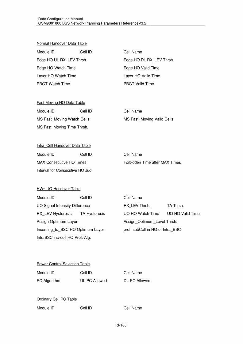
Data Configuration Manual GSM9001800 BSS Network Planning Parameters ReferenceV3.2
3-100
Normal Handover Data Table
Module ID Cell ID Cell Name
Edge HO UL RX_LEV Thrsh. Edge HO DL RX_LEV Thrsh.
Edge HO Watch Time Edge HO Valid Time
Layer HO Watch Time Layer HO Valid Time
PBGT Watch Time PBGT Valid Time
Fast Moving HO Data Table
Module ID Cell ID Cell Name
MS Fast_Moving Watch Cells MS Fast_Moving Valid Cells
MS Fast_Moving Time Thrsh.
Intra_Cell Handover Data Table
Module ID Cell ID Cell Name
MAX Consecutive HO Times Forbidden Time after MAX Times
Interval for Consecutive HO Jud.
HW~IUO Handover Table
Module ID Cell ID Cell Name
UO Signal Intensity Difference RX_LEV Thrsh. TA Thrsh.
RX_LEV Hysteresis TA Hysteresis UO HO Watch Time UO HO Valid Time
Assign Optimum Layer Assign_Optimum_Level Thrsh.
Incoming_to_BSC HO Optimum Layer pref. subCell in HO of Intra_BSC
IntraBSC inc-cell HO Pref. Alg.
Power Control Selection Table
Module ID Cell ID Cell Name
PC Algorithm UL PC Allowed DL PC Allowed
Ordinary Cell PC Table
Module ID Cell ID Cell Name

Data Configuration Manual GSM9001800 BSS Network Planning Parameters ReferenceV3.2
3-101
RX_LEV Thrsh. for UL Increase RX_LEV Thrsh. for DL Increase
P1 N1 RX_LEV Thrsh. for UL Decrease
RX_LEV Thrsh. for DL Decrease P2 N2
Qual. Thrsh. for UL Increase Qual. Thrsh. for DL Increase
P3 N3 Qual. Thrsh. for UL Decrease
Qual. Thrsh. for DL Decrease P4 N4
PC Period
BTS Power Control Table
Module ID Cell ID Cell Name
BTS PC Period DL RX_LEV Expected
DL RX_LEV Compensation Filter Length for DL RX_LEV
DL Qual. Expected Filter Length for DL Qual.
DL Qual. Compensation BTS Min Tx Power
MAX PC Step BTS Max Tx Power
PC Adj. Range
MS Power Control Table
Module ID Cell ID Cell Name
PC Interval Initial RX_LEV Expected
Filter Length for Initial RX_LEV Stable RX_LEV Expected
Filter Length for Stable RX_LEV UL RX_LEV Compensation
UL Qual. Expected Filter Length for Qual.
UL Qual. Compensation Power Increment after HO Fail.
MAX PC Step
HWII Power Control Data Table
Module ID Cell ID PC Interval
Filter Length for UL RX_LEV Filter Length for DL RX_LEV
Filter Length for UL Qual. Filter Length for DL Qual.
MR. Compensation Allowed UL MR. Number Predicted
DL MR. Number Predicted UL RX_LEV Upper Thrsh.
UL RX_LEV Lower Thrsh. UL Qual. Upper Thrsh.

Data Configuration Manual GSM9001800 BSS Network Planning Parameters ReferenceV3.2
3-102
UL Qual. Lower Thrsh. DL RX_LEV Upper Thrsh.
DL RX_LEV Lower Thrsh. DL Qual. Upper Thrsh.
DL Qual. Lower Thrsh. MAX Adj. Value for Qual. Zone 0
MAX Adj. Value for Qual. Zone 1 MAX Adj. Value for Qual. Zone 2
Adj. PC Value by RxQual. MS Min Allowed Power
BTS Max. Power BTS PC class
Channel Radio CH management ctrl. Table
Module ID Cell ID CH Allocation Algorithm
SD Dynamic Allocation Allowed Idle SD Thrsh.
Cell SD Maximum TCH Minimum Recovery Time(s)
Idle TCH Thrsh. N1 Apply_TCH Decision Period T(m)
HWII Channel Allocation Table
Module ID Cell ID SD Allocation Priority Allowed
Interf. Priority Allowed Active CH Interf. Meas.Allowed
Allocation TRX Priority Allowed History Record Priority Allowed
Balance Traffic Allowed Interf. of UL Level Thrsh.
Interf. of UL Qual. Thrsh. Interf. of DL Level Thrsh.
Interf. of DL Qual. Thrsh. Filter Length for TCH Level
Filter Length for TCHQual. Filter Length for SDCCH Level
Filter Length for SDCCH Qual. Updata Period of CH Record
Updata Freq. of CH Record
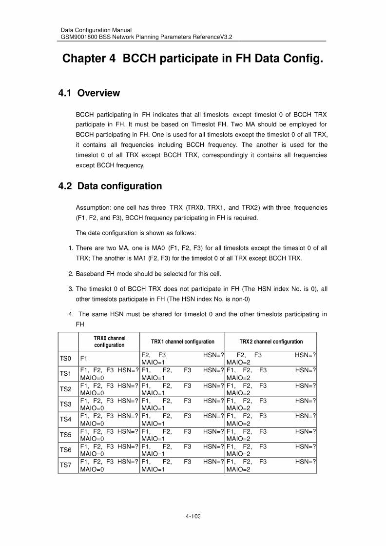
Data Configuration Manual GSM9001800 BSS Network Planning Parameters ReferenceV3.2
4-103
Chapter 4 BCCH participate in FH Data Config.
4.1 Overview
BCCH participating in FH indicates that all timeslots except timeslot 0 of BCCH TRX
participate in FH. It must be based on Timeslot FH. Two MA should be employed for
BCCH participating in FH. One is used for all timeslots except the timeslot 0 of all TRX,
it contains all frequencies including BCCH frequency. The another is used for the
timeslot 0 of all TRX except BCCH TRX, correspondingly it contains all frequencies
except BCCH frequency.
4.2 Data configuration
Assumption: one cell has three TRX (TRX0, TRX1, and TRX2) with three frequencies
(F1, F2, and F3), BCCH frequency participating in FH is required.
The data configuration is shown as follows:
1. There are two MA, one is MA0 (F1, F2, F3) for all timeslots except the timeslot 0 of all
TRX; The another is MA1 (F2, F3) for the timeslot 0 of all TRX except BCCH TRX.
2. Baseband FH mode should be selected for this cell.
3. The timeslot 0 of BCCH TRX does not participate in FH (The HSN index No. is 0), all
other timeslots participate in FH (The HSN index No. is non-0)
4. The same HSN must be shared for timeslot 0 and the other timeslots participating in
FH
TRX0 channel configuration
TRX1 channel configuration TRX2 channel configuration
TS0 F1 F2, F3 HSN=? MAIO=1
F2, F3 HSN=? MAIO=2
TS1 F1, F2, F3 HSN=?
MAIO=0
F1, F2, F3 HSN=?
MAIO=1
F1, F2, F3 HSN=?
MAIO=2
TS2 F1, F2, F3 HSN=? MAIO=0
F1, F2, F3 HSN=? MAIO=1
F1, F2, F3 HSN=? MAIO=2
TS3 F1, F2, F3 HSN=? MAIO=0
F1, F2, F3 HSN=? MAIO=1
F1, F2, F3 HSN=? MAIO=2
TS4 F1, F2, F3 HSN=?
MAIO=0
F1, F2, F3 HSN=?
MAIO=1
F1, F2, F3 HSN=?
MAIO=2
TS5 F1, F2, F3 HSN=? MAIO=0
F1, F2, F3 HSN=? MAIO=1
F1, F2, F3 HSN=? MAIO=2
TS6 F1, F2, F3 HSN=? MAIO=0
F1, F2, F3 HSN=? MAIO=1
F1, F2, F3 HSN=? MAIO=2
TS7 F1, F2, F3 HSN=?
MAIO=0
F1, F2, F3 HSN=?
MAIO=1
F1, F2, F3 HSN=?
MAIO=2

Data Configuration Manual GSM9001800 BSS Network Planning Parameters ReferenceV3.2
5-104
Chapter 5 Contrast table of RNP Parameters
between BSC04.080520 and BSC04.1120
Name of CDD for BSC04080520 version Name of CDD for BSC041120 version
BSC cell table
Module ID
Cell ID
Cell name
Cell system type
Sub-cell type
Cell level Cell Class
BS color code BCC
Network color code NCC
Reserved
CGI CGI
Installation state
SITE ID Site ID
SITE name Site name
Support GPRS
Frequency hopping table
Frequency hopping index No. FH index No.
HSN HSN
TSN TSC
Hopping Frequency 1~64 FH ARFCN 1~64
Radio channel config. table
Module ID
SITE ID Site ID
TRX ID
Channel No. CH Number
SITE name Site name
Channel type CH type
Frequency hopping index No. FH index Number
MAIO MAIO
Sub-channel No. Sub-CH Number
Trunk circuit No. Circuit Number
Timeslot No. TS Number
Sub-timeslot No. Sub-TS Number
Carrier configuration table
Module ID
Cell ID
TRX ID TRX ID
Cell name
Equipment group ID

Data Configuration Manual GSM9001800 BSS Network Planning Parameters ReferenceV3.2
5-105
Valid carrier frequency 1~64 ARFCN 1~64
Power class Static TRX Power Class
Carrier power type
Concentric cell property HW-IUO Property
TRX priority
System information table
Module ID
Cell ID
Cell name
System information use System information
Reserved
Regular transmission
Regular transmission interval
MS max. resend times MS MAX retrans
Common access control level Common Access Control Class
Special access control level Special Access Control Class
Reserved
Cell channel description format
Attach/detach permitted ATT
Power control permitted PWRC
Downlink DTX indication UL DTX
TX_integer Tx integer
CBA CBA
Emergency call permitted EC allowed
Call re-establishment permitted Call re-establishment allowed
Reserved
Country color code permitted NCC permitted
Bs_ag_blks_res BS_AG_BLKS_RES
CCCH configuration CCCH-CONF
Bs_pa_mfrms BS-PA-MFRAMS
T3212
Invalid radio link counter Radio Link Timeout
MS max. Tx power level MS_TXPWR_MAX_CCH
Reserved
MS min. Rx signal level RXLEV_ACCESS_MIN
Reserved
Add reselection para. indication ACS
Half rate supported
Cell reselection hysteresis CRH
Reserved
CBCH channel description CBCH CH Description
CBCH mobile configuration CBCH Mobile Allocation
Cell reselection parameter indi. PI
CBQ CBQ
Cell reselection offset CRO
Cell reselection temp. offset TO

Data Configuration Manual GSM9001800 BSS Network Planning Parameters ReferenceV3.2
5-106
Cell reselection penalty time PT
ECSC
Power deviation indication
Power deviation
Multiband reporting MBR
Reserved
Cell configuration table
Module ID
Cell ID
Cell name
Data service configuration Data service allowed
Reserved 1
Speech version
Reserved 2
Speech version priority Speech version priority
Encryption algorithm setting Encryption Algorithm
Cell BCCH switchover permitted BCCH mutual support
Frequency hopping mode FH Mode
TCH carrier power
BCCH carrier power
Support DRX mode SMCBC DRX
Downlink DTX applied DL DTX
Cell BCCH switchover selection BCCH mutual recover
Hopping TRX failure SO permitted BBFH TRX mutual support
Hopping TRX switchback selection BBFH TRX mutual recover
Cell allocation table
Module ID
Cell ID
Cell name
Valid carrier frequency 0~63 ARFCN 0~63
BA1(BCCH) table
Module ID
Cell ID
Cell name
BCCH Freq. of adjacent cell 1~32 BCCH of Ncell 1~32
BA2(SACCH) table
Module ID
Cell ID
Cell name
BCCH Freq. of adjacent cell 1~32 BCCH of Ncell 1~32
Cell attribute table
Module ID
Cell ID
Cell name
Interference band threshold 0 Interf. band Thrsh. 0
Interference band threshold 1 Interf. band Thrsh. 1

Data Configuration Manual GSM9001800 BSS Network Planning Parameters ReferenceV3.2
5-107
Interference band threshold 2 Interf. band Thrsh. 2
Interference band threshold 3 Interf. band Thrsh. 3
Interference band threshold 4 Interf. band Thrsh. 4
Interference band threshold 5 Interf. band Thrsh. 5
Average interference period Interf. calculation period
Number of SACCH multiframes SACCH Multi-Frames
Radio resource report period
CCCH load indication period
CCCH load threshold CCCH load Thrsh.
Max. repeat times of phys. info. Max resend times of Phy. Info.
Overload interval Overload indication period
RACH busy threshold RACH busy Thrsh.
Average RACH load timeslot Average RACH load TS number
Max RC power reduction
T200 SDCCH(5ms)
T200 FACCH/full rate(5ms) T200 FACCH/F
T200 FACCH/half rate(5ms) T200 FACCH/H
T200 SACCH TCH SAPI0(10ms) T200 SACCH TCH SAPI0
T200 SACCH TCH SAPI3(10ms) T200 SACCH TCH SAPI3
T200 SACCH SDCCH(10ms) T200 SACCH SDCCH
T200 SDCCH SAPI3(5ms) T200 SDCCH SAPI3
T3105(10ms) T3105
Max. timing advance MAX TA
Frame start time
Paging times
Random access error threshold Random access error Thrsh.
Power level Power Class
RACH min. access level
DC bias voltage threshold DC bias voltage Thrsh.
Cell extension class Cell extension type
Cell extension offset
Diversity LNA bypass permitted
Cell alarm threshold table
Module ID
Cell ID
Cell name
Power output error threshold Power output error Thrsh.
Power output reduction threshold Power output reduction Thrsh.
VSWR TRX error threshold VSWR TRX error Thrsh.
VSWR TRX unadjusted threshold VSWR TRX unadjusted Thrsh.
Cell call control table
Module ID
Cell ID
Cell name
Immediate assignment of TCH TCH immediate assignment
Immediate assign optimization Immediate assignment Opt.

Data Configuration Manual GSM9001800 BSS Network Planning Parameters ReferenceV3.2
5-108
Assign to non-random access cell Immediate assign to other cell
Assigned to other cell Assign to other cell
TCH assignment retry
Intra-cell HO from SDCCH to TCH Intra-cell SD to TCH HO
Inter-BSC HO from SDCCH to TCH Inter-cell SD to TCH HO
OM-orginated intra-cell CH HO OM start intra-cell HO
OM-orig. intra-cell HO in BSC OM start inter-cell HO(intraBSC)
OM-orig. inter-cell HO in BSC OM start inter-BSC HO
Handover retry HO retry
TCH flow alarm TCH overload alarm
Radio CH release abnormal retry RF CH abnormal release retry
Abis flow control permitted
TCH flow start TCH flow control allowed
Circuit pool function selection Circuit pool
Directed retry permitted Direct retry
Cell call control para. table
Module ID
Cell ID
Cell name
T3101(100ms)
Assign-TCH idle rate threshold Assign-TCH idle rate Thrsh.
Assign-TCH re-estb. rate thres. Assign-TCH re-Estb. rate thrsh.
TCH flow control start threshold TCH flow control start thrsh.
Max assignment retry times
Max handover retry times Max HO retry times
SDCCH to TCH HO: TCH idle rate Free TCH Thrsh. for SD to TCH HO
Max. radioCH release retry times
SDCCH-to-TCH HO request type Service type Req.(SD to TCH HO)
Outg. HO request resend interval
Outg. HO req. max. resend times Out BSC HO Req. resent times
Syst. delay frame No. adj. value
Response request selection Response on out BSC HO Req.
Cell module information table
CGI
Module ID
Handover control table
Module ID
Cell ID
Cell name
Handover algorithm type HO algorithm
Traffic channel HO min. interval Min interval for TCH HOs
New assigned HO min. interval
Signaling CH HO min. interval Min interval for SD HOs
Continuous HO min. interval Min interval for consecutive HOs
Directed retry TALLOC
New emergency HO min. interval Min interval for Emerg. HOs

Data Configuration Manual GSM9001800 BSS Network Planning Parameters ReferenceV3.2
5-109
Inter-BSC HO on SDCCH allowed Inter-BSC HO on SD allowed
Co-BSC/MSC adjustment allowed Co-BSC/MSC Adj.
Signaling channel HO allowed SD HO allowed
Penalty allowed Penalty allowed
Intra-cell handover allowed Intracell HO allowed
Load handover allowed Load HO allowed
Fast-moving HO algorithm allowed MS fast moving HO allowed
RXLEV drop HO algorithm allowed Rx_Levell_Drop HO allowed
PBGT HO algorithm allowed PBGT HO allowed
Post-HO PWR pred. alg. allowed MS power prediction after HO
BTS meas. report preprocessing M.R. Preprocessing
Transfer original meas. report Transfer original M.R.
Transfer BS/MS power level Transfer BS/MS power class
Reserved
Preprocessed meas. report freq. Sent Freq.of preprocessed M.R.
Cell description table
Module ID
Cell ID
Cell name
BCCH
CGI CGI
Network color code NCC
BS color code BCC
Reserved
Layer of the cell
Cell priority
Cell type
Inter-layer handover threshold Inter-layer HO Thrsh.
Inter layer handover hysteresis Inter-layer HO hysteresis
Speed penalty value Penalty on MS Fast moving HO
Speed penalty duration Penalty time on Fast moving HO
BCCH carrier transmission power
NON_BCCH transmission power
MS max. Tx power level MS_TXPWR_MAX_CCH
Min DL power of candidate cell Min DL level on candidate cell
Uplink optimal Rx level UL expected level at HO access
External cell description table
External cell ID
Cell name
BCCH
CGI CGI
Network color code NCC
BS color code BCC
Share MSC flag Co-MSC
Reserved
Layer of the cell
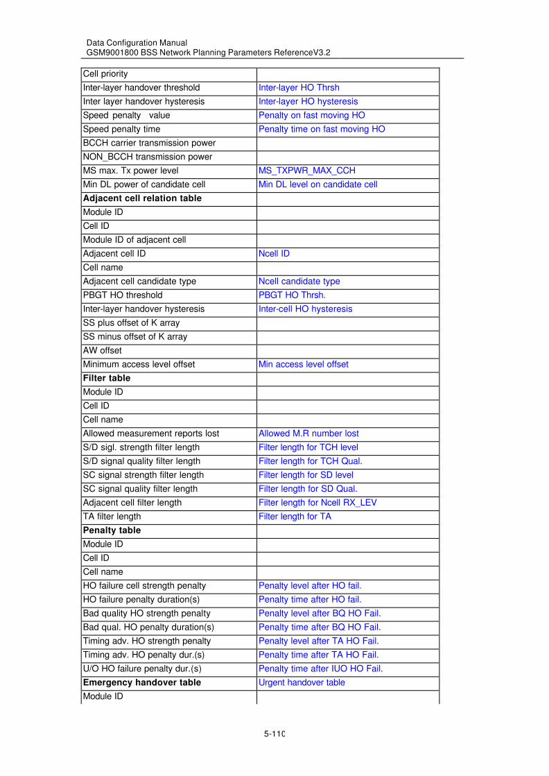
Data Configuration Manual GSM9001800 BSS Network Planning Parameters ReferenceV3.2
5-110
Cell priority
Inter-layer handover threshold Inter-layer HO Thrsh
Inter layer handover hysteresis Inter-layer HO hysteresis
Speed penalty value Penalty on fast moving HO
Speed penalty time Penalty time on fast moving HO
BCCH carrier transmission power
NON_BCCH transmission power
MS max. Tx power level MS_TXPWR_MAX_CCH
Min DL power of candidate cell Min DL level on candidate cell
Adjacent cell relation table
Module ID
Cell ID
Module ID of adjacent cell
Adjacent cell ID Ncell ID
Cell name
Adjacent cell candidate type Ncell candidate type
PBGT HO threshold PBGT HO Thrsh.
Inter-layer handover hysteresis Inter-cell HO hysteresis
SS plus offset of K array
SS minus offset of K array
AW offset
Minimum access level offset Min access level offset
Filter table
Module ID
Cell ID
Cell name
Allowed measurement reports lost Allowed M.R number lost
S/D sigl. strength filter length Filter length for TCH level
S/D signal quality filter length Filter length for TCH Qual.
SC signal strength filter length Filter length for SD level
SC signal quality filter length Filter length for SD Qual.
Adjacent cell filter length Filter length for Ncell RX_LEV
TA filter length Filter length for TA
Penalty table
Module ID
Cell ID
Cell name
HO failure cell strength penalty Penalty level after HO fail.
HO failure penalty duration(s) Penalty time after HO fail.
Bad quality HO strength penalty Penalty level after BQ HO Fail.
Bad qual. HO penalty duration(s) Penalty time after BQ HO Fail.
Timing adv. HO strength penalty Penalty level after TA HO Fail.
Timing adv. HO penalty dur.(s) Penalty time after TA HO Fail.
U/O HO failure penalty dur.(s) Penalty time after IUO HO Fail.
Emergency handover table Urgent handover table
Module ID

Data Configuration Manual GSM9001800 BSS Network Planning Parameters ReferenceV3.2
5-111
Cell ID
Cell name
Emergency TA handover threshold TA Thrsh.
Emergency HO DL qual. threshold DL Qual. Thrsh.
Emergency HO UL qual. threshold UL Qual. Thrsh.
Intf. HO UL quality threshold UL Qual. Thrsh. for interf.HO
Intf. HO DL quality threshol DL Qual. Thrsh. for interf.HO
Intf. HO UL Rx PWR threshold UL RX_LEV Thrsh. for interf.HO
Intf. HO DL Rx PWR threshold DL RX_LEV Thrsh. for interf.HO
Uplink level SHTM filter length
Filter parameter A1~A8
Filter parameter B
Minimum timing advance MIN TA
Load handover table
Module ID
Cell ID
Cell name
Load HO flow level threshold System flux Thrsh. for load HO
Load HO start threshold Load HO Thrsh.
Load HO Rx threshold Load Req. on candidate cell
Load HO bandwidth
Graded load HO cycle Load HO step period
Graded load HO step Load HO step level
Normal handover table Normal handover data table
Module ID
Cell ID
Cell name
Uplink Rxlev border HO threshold Edge HO UL RX_LEV Thrsh.
DL Rxlev border HO threshold Edge HO DL RX_LEV Thrsh.
Border HO measurement time Edge HO watch time
Border HO duration Edge HO valid time
Inter-layer HO measurement time Layer HO watch time
Inter-layer HO duration Layer HO valid time
PBGT measurement time(s) PBGT watch time
PBGT duration(s) PBGT valid time
Fast-moving handover table MS fast moving HO data table
Module ID
Cell ID
Cell name
Fast-moving cell meas. number MS Fast-moving Watch cells
Fast-moving cell actual number MS Fast-moving Valid cells
Fast-moving time threshold MS Fast-moving time Thrsh.
Intra-cell cont. HO ctrl. table Intra-cell Handover data table
Module ID
Cell ID
Cell name

Data Configuration Manual GSM9001800 BSS Network Planning Parameters ReferenceV3.2
5-112
Max consecutive handover times MAX consecutive HO times
Barred dur. after max. time(s) Forbidden time after MAX times
Presumed consecutive interval Interval for consecutive HO Jud.
GSM0508 handover table
Module ID
Cell ID
Cell name
Uplink HO Rx level threshold UL HO Rx_LEVEL Thrsh.
Downlink HO Rx level threshold DL HO RX_LEV Thrsh.
N5
P5
Uplink HO Rx quality threshold UL HO RX_QUAL Thrsh.
Downlink HO Rx quality threshold DL HO RX_QUAL Thrsh.
N6
P6
Uplink intra-cell HO Rx level UL Intra-cell HO RX_LEV
Downlink intra-cell HO Rx level DL Intra-cell HO RX_LEV
N7
P7
TA value handover permitted TA HO Allowed
N8
P8
Power control selection table
Module ID
Cell ID
Cell name
Power control alg. selection PC algorithm
Uplink power control permitted UL PC allowed
Downlink power control permitted DL PC allowed
Ordinary cell power control data Ordinary cell PC table
Module ID
Cell ID
Cell name Cell name
UL increment Rx level threshold RX_LEV Thrsh. for UL increase
DL increment RX level threshold RX_LEV Thrsh. for DL increase
P1
N1
UL decrement Rx level threshold RX_LEV Thrsh. for UL decrease
DL decrement RX level threshold RX_LEV Thrsh. for DL decrease
P2
N2
UL increment Rx qual. threshold Qual. Thrsh. for UL increase
DL increment RX qual. threshold Qual. Thrsh. for DL increase
P3
N3
UL decrement Rx qual. threshold Qual. Thrsh. for UL decrease

Data Configuration Manual GSM9001800 BSS Network Planning Parameters ReferenceV3.2
5-113
DL decrement RX qual. threshold Qual. Thrsh. for DL decrease
P4
N4
Power control adjustment period PC period
BTS power control table
Module ID
Cell ID
Cell name Cell name
Power control adjustment period BTS PC period
BTS power control in SDCCH BTS PC in SD
Expected stable downlink level DL RX_LEV expected
Downlink level filter length Filter length for DL RX_LEV
Downlink loss compen. fact. DL RX_LEV compensation
Expected downlink quality DL Qual. expected
Downlink quality filter length Filter length for DL Qual.
Downlink quality compen. factor DL Qual. compensation
Min. BTS transmitting power BTS min Tx power
Max. power control step MAX PC step
Max. BTS transmitting power BTS max Tx power
BTS Power control level PC Adj. range
MS power control table MS power control data
Module ID
Cell ID
Cell name Cell name
Registration period PC interval
Power control adjustment period MS PC period
Expected initial signal level Initial RX_LEV expected
Init. adj. phase filter length Filter length for initial RX_LEV
Expt. stable state signal level stable RX_LEV expected
Stable phase signal filter len. Filter length for stable RX_LEV
Uplink compensation factor UL RX_LEV compensation
Expected uplink quality UL Qual. expected
Stable phase quality filter len. Filter length for Qual.
Uplink quality compen. factor UL Qual. compensation
PWR incr. range after HO failure Power increment after HO Fail.
Max. power control step MAX PC step
Radio CH management ctrl. table
Module ID
Cell ID
Cell name
Channel allocation algorithm CH allocation algorithm
Intf. band preprecessing switch Intf. band preprecessing allowed
Intf. band filter start length
Average interference band width
SDCCH dynamic allocation flag SD dynamic allocation allowed
Idle SDCCH channel threshold Idle SD Thrsh.

Data Configuration Manual GSM9001800 BSS Network Planning Parameters ReferenceV3.2
5-114
Cell SDCCH channel maximum Cell SD maximum
TCH minimum recovery time(s)
Idle TCH channel threshold N1 Idle TCH Thrsh. N1
Apply-TCH decision period T(m)
Bad CH management control table
Module ID
Cell ID
Cell name
Bad channel management switch Bad CH management allowed
Bad channel definition threshold Bad CH definition Thrsh.
Bad channel alarm threshold Bad CH alarm Thresh.
HW II power control table
Module ID
Cell ID
Power control adjustment period PC interval
Uplink level filter length Filter length for UL RX_LEV
Downlink level filter length Filter length for DL RX_LEV
Uplink quality filter length Filter length for UL Qual.
Downlink quality filter length Filter length for DL Qual.
Meas. report compensation switch M.R. Compensation allowed
UL pre-measure report number UL M.R. number predicted
DL pre-measure report number DL M.R. number predicted
UL S-strength upper threshold UL RX_LEV upper Thrsh.
UL S-strength lower threshold UL RX_LEV lower Thrsh.
UL S-quality upper threshold UL Qual. upper Thrsh.
UL S-quality lower threshold UL Qual. lower Thrsh.
DL S-strength upper threshold DL RX_LEV upper Thrsh.
DL S-strength lower threshold DL RX_LEV lower Thrsh.
DL S-quality upper threshold DL Qual. upper Thrsh.
DL S-quality lower threshold DL Qual. lower Thrsh.
Quality zone 0 max dj. step MAX Adj. value for Qual. zone 0
Quality zone 1 max adj. step MAX Adj. value for Qual. zone 1
Quality zone 2 max adj. step MAX Adj. value for Qual. zone 2
quality-based power adj. step Adj. PC value by RxQual.
MS min. power allowed MS min allowed power
MS max. power allowed MS max allowed power
BTS max. transmitting power BTS max. power
BTS power control level BTS PC class
HWII Channel allocation table
SDCCH optimal allocation allowed SD allocation priority allowed
Interfering priority allowed Interf. priority allowed
Interf. meas. of occupied ch. Active CH interf. Meas.allowed
TRX priority allowed Allocation TRX priority allowed
History log priority allowed History record priority allowed
Channel traffic balance allowed Balance traffic allowed

Data Configuration Manual GSM9001800 BSS Network Planning Parameters ReferenceV3.2
5-115
UL interf. strength threshold Interf. of UL level Thrsh.
UL interf. quality threshold Interf. of UL Qual. Thrsh.
DL interf. strength threshold Interf. of DL level Thrsh.
DL interf. quality threshold Interf. of DL Qual. Thrsh.
TCH/data strength filter length Filter length for speech/data level
TCH/data quality filter length Filter length for speech/data Qual.
SDCCH strength filter length Filter length for Signaling level
SDCCH quality filter length Filter length for Signaling Qual.
History log's update period(m) Updata Period of CH occupied record
History log's update step Updata Freq. of CH occupied record
Concentric cell handover table HW-IUO Handover Table
Module ID
Cell ID
U/O signal intensity difference UO signal intensity difference
Rx level threshold RX-LEV Thrsh.
Rx level hysteresis RX-LEV Hysteresis
TA threshold TA Thrsh.
TA hysteresis
U/O HO measurement time(s) UO HO watch time
U/O HO duration(s) UO HO valid time
Assign optimum layer
Assign-optimum-level threshold Assign-optimum-level thrsh.
pref. subcell in HO of intra-BSC
Incoming-to-BSC HO optimum layer