huawei technologies co., ltd. - huawei enterprise - a better way
TRANSCRIPT
Issue
Date
HUAWEI TECHNOLOGIES CO., LTD.

Issue () Huawei Proprietary and Confidential
Copyright © Huawei Technologies Co., Ltd. i
Copyright © Huawei Technologies Co., Ltd. 2012. All rights reserved.
No part of this document may be reproduced or transmitted in any form or by any means without prior
written consent of Huawei Technologies Co., Ltd.
Trademarks and Permissions
and other Huawei trademarks are trademarks of Huawei Technologies Co., Ltd.
All other trademarks and trade names mentioned in this document are the property of their respective
holders.
Notice
The purchased products, services and features are stipulated by the contract made between Huawei and
the customer. All or part of the products, services and features described in this document may not be
within the purchase scope or the usage scope. Unless otherwise specified in the contract, all statements,
information, and recommendations in this document are provided "AS IS" without warranties, guarantees or
representations of any kind, either express or implied.
The information in this document is subject to change without notice. Every effort has been made in the
preparation of this document to ensure accuracy of the contents, but all statements, information, and
recommendations in this document do not constitute a warranty of any kind, express or implied.
Huawei Technologies Co., Ltd.
Address: Huawei Industrial Base
Bantian, Longgang
Shenzhen 518129
People's Republic of China
Website: http://www.huawei.com
Email: [email protected]

Contents
Issue () Huawei Proprietary and Confidential
Copyright © Huawei Technologies Co., Ltd.
ii
About This Document
Purpose
This document describes the hardware structure of the NE40E-X1 and NE40E-X2, including
power modules, a heat dissipation system, and cables. This document also provides a list of
acronyms and abbreviations.
Intended Audience
This document is intended for:
Network planning and design engineers
Hardware installation engineers
Commissioning engineers
Maintenance engineers
Symbol Conventions
The symbols that may be found in this document are defined as follows.
Symbol Description
Alerts you to a high risk hazard that could, if not
avoided, result in serious injury or death.
Alerts you to a medium or low risk hazard that could, if
not avoided, result in moderate or minor injury.
Alerts you to a potentially hazardous situation that could,
if not avoided, result in equipment damage, data loss,
performance deterioration, or unanticipated results.
Provides a tip that may help you solve a problem or save
time.
Provides additional information to emphasize or
supplement important points in the main text.

Contents
Issue () Huawei Proprietary and Confidential
Copyright © Huawei Technologies Co., Ltd.
iii

Contents
Issue () Huawei Proprietary and Confidential
Copyright © Huawei Technologies Co., Ltd.
iv
Contents
About This Document .................................................................................................................... ii
1 NE40E-X1 Hardware Description ............................................................................................... 1
1.1 Overview .......................................................................................................................................................... 1
1.1.1 System Hardware Description................................................................................................................. 1
1.1.2 System Architecture ................................................................................................................................ 2
1.1.3 Main System Features ............................................................................................................................. 3
1.1.4 System configuration .............................................................................................................................. 3
1.1.5 Main Parts of the NE40E-X1 .................................................................................................................. 3
1.1.6 Number of Main Parts and Slot Layout of the NE40E-X1 ..................................................................... 4
1.2 Power Supply System....................................................................................................................................... 6
1.2.1 Architecture of the Power Supply System ............................................................................................... 6
1.2.2 Diagram of the Power Supply Architecture ............................................................................................ 6
1.2.3 DC Power Supply System ....................................................................................................................... 7
1.2.4 AC Power Supply System ....................................................................................................................... 8
1.3 Heat Dissipation System ................................................................................................................................ 10
1.3.1 System Air Channel .............................................................................................................................. 11
1.3.2 Fan Module ........................................................................................................................................... 11
1.4 Data Plane ...................................................................................................................................................... 13
1.4.1 Introduction to the Data Plane............................................................................................................... 13
1.4.2 Introduction to the NPUI-20 ................................................................................................................. 14
1.5 Control Plane .................................................................................................................................................. 16
1.5.1 Introduction to the Control Plane .......................................................................................................... 16
1.5.2 MPUG ................................................................................................................................................... 17
1.6 Physical Specifications ................................................................................................................................... 20
1.6.1 Chassis Specifications ........................................................................................................................... 20
1.6.2 Board Specifications ............................................................................................................................. 21
2 NE40E-X2 Hardware Description ............................................................................................. 23
2.1 Overview ........................................................................................................................................................ 23
2.1.1 Hardware Description ........................................................................................................................... 23
2.1.2 System Architecture .............................................................................................................................. 24
2.1.3 Main System Features ........................................................................................................................... 25
2.1.4 System configuration ............................................................................................................................ 26
Contents
Issue () Huawei Proprietary and Confidential
Copyright © Huawei Technologies Co., Ltd.
v
2.1.5 Main Parts of the NE40E-X2 ................................................................................................................ 26
2.1.6 Number of Main Parts and Slot Layout of the NE40E-X2 ................................................................... 27
2.2 Power Supply System..................................................................................................................................... 29
2.2.1 Architecture of the Power Supply System ............................................................................................. 29
2.2.2 Diagram of the Power Supply Architecture .......................................................................................... 30
2.2.3 DC Power Supply System ..................................................................................................................... 30
2.2.4 AC Power Supply System ..................................................................................................................... 32
2.3 Heat Dissipation System ................................................................................................................................ 34
2.3.1 Air Channel ........................................................................................................................................... 34
2.3.2 Fan Module ........................................................................................................................................... 35
2.4 Data Plane ...................................................................................................................................................... 38
2.4.1 Introduction to the Data Plane............................................................................................................... 38
2.4.2 Introduction to the NPUI-20 ................................................................................................................. 39
2.5 Control Plane .................................................................................................................................................. 41
2.5.1 Introduction to the Control Plane .......................................................................................................... 41
2.5.2 MPUG ................................................................................................................................................... 42
2.6 Physical Specifications ................................................................................................................................... 46
2.6.1 Chassis Specifications ........................................................................................................................... 46
2.6.2 Board Specifications ............................................................................................................................. 47
3 Boards ............................................................................................................................................ 48
3.1 8-Port 100/1000Base-X-SFP High-speed Interface Card (HIC) .................................................................... 48
3.2 8-Port 100/1000Base-X-SFP High-speed Interface Card A (HIC, Supporting 1588v2) ................................ 53
3.3 4-Port 100/1000Base-X-SFP High-speed Interface Card(HIC) ..................................................................... 57
3.4 4-Port OC-3c/STM-1c POS-SFP Flexible Interface Card (FIC) .................................................................... 62
3.5 8-Port 100Base-X-SFP Flexible Interface Card (FIC, Supporting 1588v2) ................................................... 65
3.6 8-Port 100Base-RJ45 Flexible Interface Card (FIC, Supporting 1588v2) ..................................................... 69
3.7 16-Port E1(75ohm) Flexible Interface Card (FIC) ......................................................................................... 72
3.8 16-Port E1(120ohm) Flexible Interface Card (FIC) ....................................................................................... 74
3.9 Auxiliary Flexible Interface Card with 4-Port 100Base-RJ45(FIC, Supporting 1588v2) .............................. 77
3.10 1-Port Channelized OC3c/STM1c POS-SFP Flexible Interface Card (FIC) ................................................ 82
3.11 4-Port OC-3c/STM-1c ATM SFP Flexible Interface Card (FIC) .................................................................. 85
4 Cables ............................................................................................................................................ 89
4.1 Power Cable ................................................................................................................................................... 90
4.1.1 DC Power Cables .................................................................................................................................. 90
4.1.2 AC Power Cables .................................................................................................................................. 91
4.2 Chassis and Cabinet Grounding Cable ........................................................................................................... 91
4.2.1 Introduction ........................................................................................................................................... 91
4.2.2 Structure ................................................................................................................................................ 91
4.2.3 Technical Specifications ........................................................................................................................ 92
4.3 Console Port Cable ......................................................................................................................................... 92
4.3.1 Introduction ........................................................................................................................................... 92

Contents
Issue () Huawei Proprietary and Confidential
Copyright © Huawei Technologies Co., Ltd.
vi
4.3.2 Structure ................................................................................................................................................ 92
4.3.3 Technical Specifications ........................................................................................................................ 93
4.4 Auxiliary Port Cable ....................................................................................................................................... 94
4.4.1 Introduction ........................................................................................................................................... 94
4.4.2 Structure ................................................................................................................................................ 94
4.4.3 Technical Specifications ........................................................................................................................ 95
4.5 Clock Cable .................................................................................................................................................... 96
4.5.1 Introduction ........................................................................................................................................... 96
4.5.2 Structure ................................................................................................................................................ 96
4.5.3 Technical Specifications ........................................................................................................................ 97
4.6 Ethernet Cable ................................................................................................................................................ 97
4.6.1 Introduction ........................................................................................................................................... 98
4.6.2 Structure ................................................................................................................................................ 98
4.6.3 Technical Specifications ...................................................................................................................... 100
4.7 Optical Fiber................................................................................................................................................. 100
4.7.1 Introduction ......................................................................................................................................... 100
4.7.2 Optical Connectors .............................................................................................................................. 101
4.7.3 Technical Specifications ...................................................................................................................... 102
4.8 16xE1 Cable ................................................................................................................................................. 102
4.8.1 Overview ............................................................................................................................................. 102
4.8.2 Structure .............................................................................................................................................. 102
4.8.3 Technical Specifications ...................................................................................................................... 106
4.9 Alarm Input/Output Cables .......................................................................................................................... 107
4.9.1 Introduction ......................................................................................................................................... 107
4.9.2 Structure .............................................................................................................................................. 107
4.9.3 Technical Specifications ...................................................................................................................... 109
A List of Indicators ...................................................................................................................... 110
A.1 Indicators on the NE40E-X1 ....................................................................................................................... 110
A.1.1 Indicators on a Fan Module ................................................................................................................ 110
A.1.2 Indicators on a PSU ............................................................................................................................ 110
A.1.3 Indicators on an MPU ........................................................................................................................ 111
A.1.4 Indicators on an NPU ......................................................................................................................... 112
A.1.5 Indicators on a Flexible Card ............................................................................................................. 113
A.2 Indicators on the NE40E-X2 ....................................................................................................................... 114
A.2.1 Fan Module Indicators ....................................................................................................................... 114
A.2.2 Power Module Indicators ................................................................................................................... 114
A.2.3 MPU Indicators .................................................................................................................................. 114
A.2.4 NPU Indicators ................................................................................................................................... 115
A.2.5 FIC Indicators .................................................................................................................................... 116
B List of Boards ............................................................................................................................. 118
B.1 List of Boards .............................................................................................................................................. 118

Contents
Issue () Huawei Proprietary and Confidential
Copyright © Huawei Technologies Co., Ltd.
vii
B.2 Board Power Consumption and Weight ....................................................................................................... 119
C List of Interface Attributes ..................................................................................................... 121
C.1 Interface Attributes of 100Base-TX/1000Base-T-RJ45 ............................................................................... 121
C.2 Interface Attributes of 1000Base-X-SFP ..................................................................................................... 121
C.3 Interface Attributes of 10GBase LAN/WAN-XFP ...................................................................................... 122
C.4 Interface Attributes of OC-3c/STM-1c POS-SFP ........................................................................................ 123
C.5 E1 Interface Attributes ................................................................................................................................. 124
C.6 Interface Attributes of OC-3c/STM-1c ATM SFP ....................................................................................... 125
D Optical Module ........................................................................................................................ 127
D.1 Instructions on How to Use an Optical Module .......................................................................................... 127
D.2 155 Mbit/s SFP/eSFP Optical Module ........................................................................................................ 130
D.3 1 Gbit/s Electrical Transceiver .................................................................................................................... 135
D.4 1.25 Gbit/s SFP/eSFP Optical Module ........................................................................................................ 136
D.5 10 Gbit/s XFP Optical Module .................................................................................................................... 145
E Glossary ...................................................................................................................................... 151
F Acronyms and Abbreviations ................................................................................................. 153
1 NE40E-X1 Hardware Description
Issue () Huawei Proprietary and Confidential
Copyright © Huawei Technologies Co., Ltd.
1
1 NE40E-X1 Hardware Description
About This Chapter
1.1 Overview
1.2 Power Supply System
1.3 Heat Dissipation System
1.4 Data Plane
1.5 Control Plane
1.6 Physical Specifications
1.1 Overview
The NE40E-X1 is a high-end network device developed by Huawei. This device is based on
the VRP and applies to the access, convergence, and transmission of Metro services.
The NE40E-X1 has great capabilities for network access, Layer 2 switching, and EoMPLS
transmission, and supports a wide range of high-speed and low-speed interfaces. In addition,
the NE40E-X1 supports triple-play of voice, video, and data services and can bear 2G, 3G, and
LTE services simultaneously. The NE40E-X1 can be deployed together with Huawei NE, CX,
and ME series products to build a hierarchical Metro Ethernet network that offers extensive
services.
1.1.1 System Hardware Description
By adopting a centralized routing engine and NP forwarding structure, the NE40E-X1 has a
great capacity and can provide diverse services.
The NE40E-X1 has an integrated chassis that can be installed independently. The main parts
of the NE40E-X1 such as MPUs, NPUs, PICs, fan modules, and PSUs are hot-swappable.
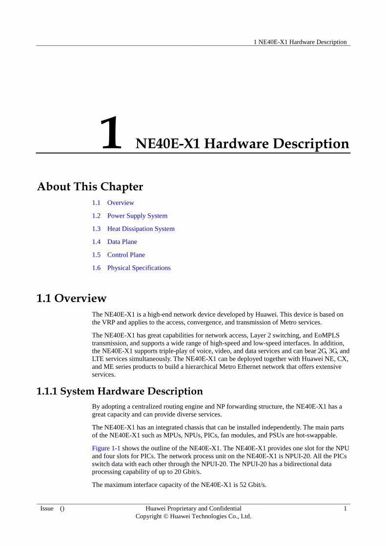
Figure 1-1 shows the outline of the NE40E-X1. The NE40E-X1 provides one slot for the NPU
and four slots for PICs. The network process unit on the NE40E-X1 is NPUI-20. All the PICs
switch data with each other through the NPUI-20. The NPUI-20 has a bidirectional data
processing capability of up to 20 Gbit/s.
The maximum interface capacity of the NE40E-X1 is 52 Gbit/s.

1 NE40E-X1 Hardware Description
Issue () Huawei Proprietary and Confidential
Copyright © Huawei Technologies Co., Ltd.
2
Figure 1-1 Outline of the NE40E-X1
1.1.2 System Architecture
The logical architecture of the NE40E consists of the following planes: data plane, control and
management plane, and monitoring plane, as shown in Figure 1-2. The data plane processes
and switches data packets quickly and smoothly; the control and management plane, as the
core of the system, controls and manages the system; the monitoring plane monitors the
ambient operating conditions.
Figure 1-2 Diagram of the system architecture
Monitoring plane
Control and management plane
Data plane
MPU
NPUI Pic *N
Management unit
NPUI
Forwarding unit
System monitoring unit
MPU
Data channel
System monitoring unit
System monitoring unit
System monitoring unit
Management unit
PIC management unit
Forwarding unit
NE40E-X2 has two NPUI boards, and NE40E-X1 has only one NPUI board.

1 NE40E-X1 Hardware Description
Issue () Huawei Proprietary and Confidential
Copyright © Huawei Technologies Co., Ltd.
3
1.1.3 Main System Features
The main features of the system include:
NP-based forwarding which enables fast service deployment
Compact structure which increases the port density
Separation of the control channels, service channels, and monitoring channels, which
ensures the connectivity of control channels and monitoring channels
High-level carrier-class reliability and manageability
Module-level shielding which meets Electro Magnetic Compatibility (EMC)
requirements
Hot-swappable boards, PSUs, and fan modules
1:1 backup of MPUs
Backup for key parts such as PSUs, fan modules, clocks, and management buses
Protection against incorrect insertion of boards
Queries about alarm prompts, alarm indications, running status, and alarm status of PSUs
Queries about alarm prompts, alarm indications, running status, and alarm status of the
voltage and ambient temperature
1.1.4 System configuration
Table 1-1 System configuration list of the NE40E-X1
Item Description
Processing unit Main frequency: 1.3GHz
SDRAM 2 GB
Flash 32 MB
CF card 1 GB
Switching capacity 20 Gbit/s (bidirectional)
Interface capacity 52 Gbit/s
Number of NPU slots 1
Number of PIC slots 4
Number of MPU slots 2
Maximum port rate supported by
PICs or NPU
10 Gbit/s
1.1.5 Main Parts of the NE40E-X1
The NE40E-X1 has an integrated chassis with main parts that all support hot swapping.
Figure 1-3 shows the outline and parts of the NE40E-X1.

1 NE40E-X1 Hardware Description
Issue () Huawei Proprietary and Confidential
Copyright © Huawei Technologies Co., Ltd.
4
Figure 1-3 Outline and parts of the NE40E-X1
1. NPU 2. PIC 3. MPU 4. Cabling rack
5. PSU 6. ESD jack 7. Grounding
Terminal
8. Air intake
vent
9. Rack-mounting
ear
10. Grounding
Terminal
11. Fan module
1.1.6 Number of Main Parts and Slot Layout of the NE40E-X1
Figure 1-4 shows the slot layout of the NE40E-X1.
Figure 1-4 Slot layout of the NE40E-X1
10
FAN
8 PSU 9 PSU
1 NPU
5 FIC/HIC4 FIC/HIC
3 FIC/HIC
6 MPU 7 MPU
2 FIC/HIC
Table 1-2 Number and layout of slots on the NE40E-X1
Slot No. Quantity
Remarks
1 1 For NPUs.
2, 3, 4, and 5 4 For sub-cards, which include HICs and FICs.
1 NE40E-X1 Hardware Description
Issue () Huawei Proprietary and Confidential
Copyright © Huawei Technologies Co., Ltd.
5
Slot No. Quantity
Remarks
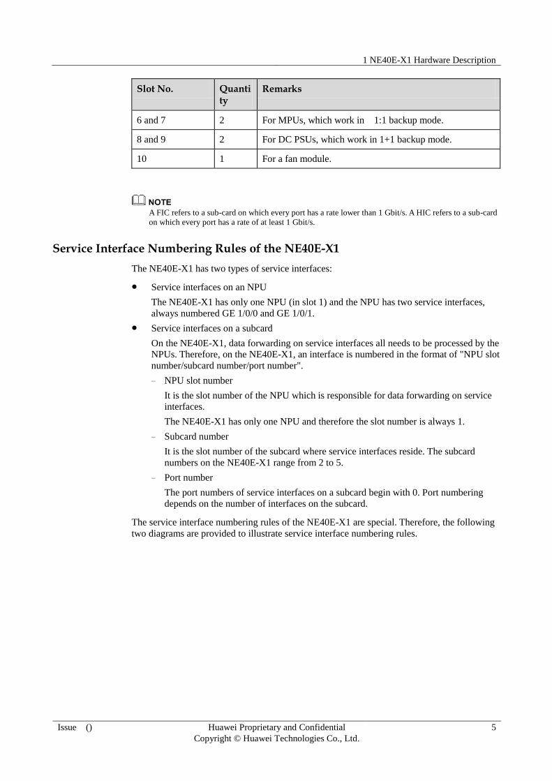
6 and 7 2 For MPUs, which work in 1:1 backup mode.
8 and 9 2 For DC PSUs, which work in 1+1 backup mode.
10 1 For a fan module.
A FIC refers to a sub-card on which every port has a rate lower than 1 Gbit/s. A HIC refers to a sub-card
on which every port has a rate of at least 1 Gbit/s.
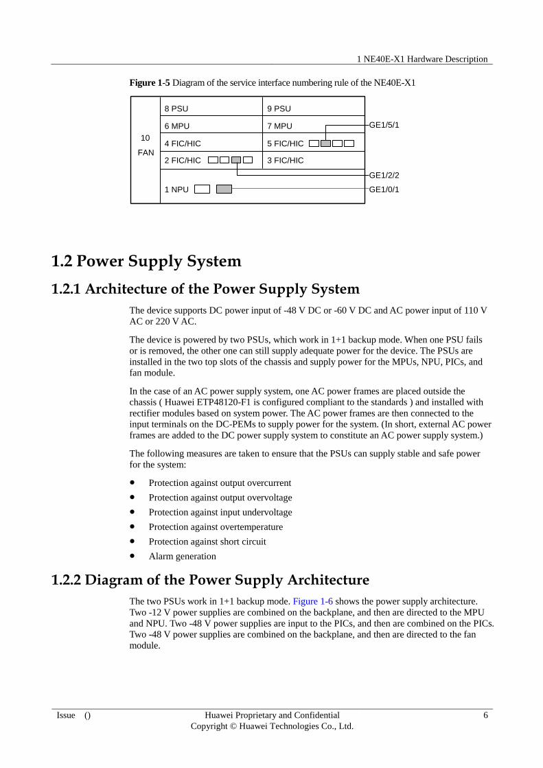
Service Interface Numbering Rules of the NE40E-X1
The NE40E-X1 has two types of service interfaces:
Service interfaces on an NPU
The NE40E-X1 has only one NPU (in slot 1) and the NPU has two service interfaces,
always numbered GE 1/0/0 and GE 1/0/1.
Service interfaces on a subcard
On the NE40E-X1, data forwarding on service interfaces all needs to be processed by the
NPUs. Therefore, on the NE40E-X1, an interface is numbered in the format of "NPU slot
number/subcard number/port number".
− NPU slot number
It is the slot number of the NPU which is responsible for data forwarding on service
interfaces.
The NE40E-X1 has only one NPU and therefore the slot number is always 1.
− Subcard number
It is the slot number of the subcard where service interfaces reside. The subcard
numbers on the NE40E-X1 range from 2 to 5.
− Port number
The port numbers of service interfaces on a subcard begin with 0. Port numbering
depends on the number of interfaces on the subcard.
The service interface numbering rules of the NE40E-X1 are special. Therefore, the following
two diagrams are provided to illustrate service interface numbering rules.
1 NE40E-X1 Hardware Description
Issue () Huawei Proprietary and Confidential
Copyright © Huawei Technologies Co., Ltd.
6
Figure 1-5 Diagram of the service interface numbering rule of the NE40E-X1
10
FAN
8 PSU 9 PSU
1 NPU
5 FIC/HIC4 FIC/HIC
3 FIC/HIC
6 MPU 7 MPU
2 FIC/HIC
GE1/5/1
GE1/2/2
GE1/0/1
1.2 Power Supply System
1.2.1 Architecture of the Power Supply System
The device supports DC power input of -48 V DC or -60 V DC and AC power input of 110 V
AC or 220 V AC.
The device is powered by two PSUs, which work in 1+1 backup mode. When one PSU fails
or is removed, the other one can still supply adequate power for the device. The PSUs are
installed in the two top slots of the chassis and supply power for the MPUs, NPU, PICs, and
fan module.
In the case of an AC power supply system, one AC power frames are placed outside the
chassis ( Huawei ETP48120-F1 is configured compliant to the standards ) and installed with
rectifier modules based on system power. The AC power frames are then connected to the
input terminals on the DC-PEMs to supply power for the system. (In short, external AC power
frames are added to the DC power supply system to constitute an AC power supply system.)
The following measures are taken to ensure that the PSUs can supply stable and safe power
for the system:
Protection against output overcurrent
Protection against output overvoltage
Protection against input undervoltage
Protection against overtemperature
Protection against short circuit
Alarm generation
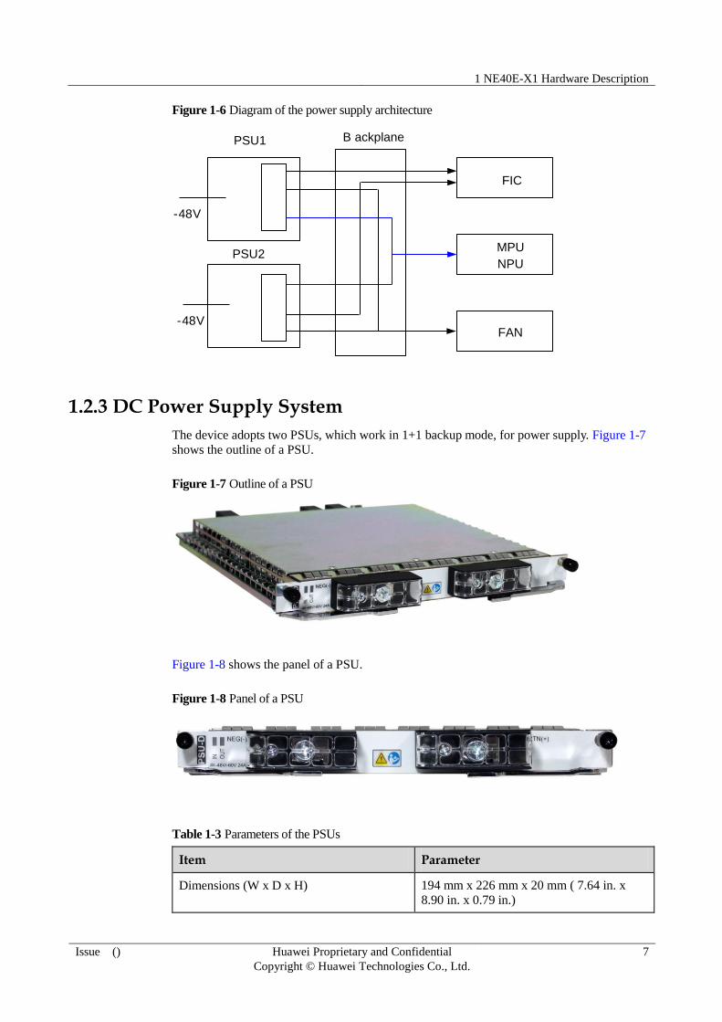
1.2.2 Diagram of the Power Supply Architecture
The two PSUs work in 1+1 backup mode. Figure 1-6 shows the power supply architecture.
Two -12 V power supplies are combined on the backplane, and then are directed to the MPU
and NPU. Two -48 V power supplies are input to the PICs, and then are combined on the PICs.
Two -48 V power supplies are combined on the backplane, and then are directed to the fan
module.
1 NE40E-X1 Hardware Description
Issue () Huawei Proprietary and Confidential
Copyright © Huawei Technologies Co., Ltd.
7
Figure 1-6 Diagram of the power supply architecture
PSU1
-48V
NPU
FAN
B ackplane
MPUPSU2
-48V
FIC
1.2.3 DC Power Supply System
The device adopts two PSUs, which work in 1+1 backup mode, for power supply. Figure 1-7
shows the outline of a PSU.
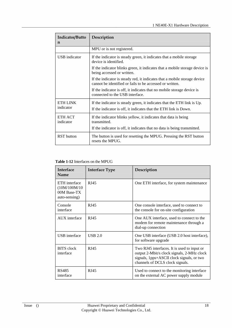
Figure 1-7 Outline of a PSU
Figure 1-8 shows the panel of a PSU.
Figure 1-8 Panel of a PSU
Table 1-3 Parameters of the PSUs
Item Parameter
Dimensions (W x D x H) 194 mm x 226 mm x 20 mm ( 7.64 in. x
8.90 in. x 0.79 in.)

1 NE40E-X1 Hardware Description
Issue () Huawei Proprietary and Confidential
Copyright © Huawei Technologies Co., Ltd.
8
Item Parameter
Weight 1 kg ( 2.21 lb )
Rated voltage -48 V DC or -60 V DC
Input voltage range -38 V DC to -72 V DC
Maximum input current 24 A
Maximum output power 905 W
Table 1-4 Description of the indicators on the PSUs
Indicator Name Description
OUT When the indicator is steady green, it indicates that the PSUs work
normally and supply stable power.
When the indicator is steady red, it indicates that the hardware of
the PSUs fails or the device is not supplied with power ranging
from -48 V or -60 V.
When the indicator is off, it indicates that the PSUs are switched
off or the hardware of the PSUs is faulty.
IN When the indicator is steady green, it indicates that the power input
is normal.
When the indicator is off, it indicates that the device is not supplied
with power ranging from -48 V or -60 V.
Notes on DC power monitoring:
The DC power monitoring channel can implement real-time monitoring on power supply.
In addition, the DC power monitoring channel allows you to query the manufacturing ID,
input voltage, and temperature of the PSUs in real time, and supports real-time reporting
of power supply alarms.
Notes on the configuration of DC power cables:
You do not need to connect protection ground cables to the PSUs, but the protection
ground cable for the chassis must be properly grounded. DC power cables include a -48
V power cable and a return (RTN) ground cable. The required cable length depends on
the distance between the cabinet and the power distribution cabinet for the device. The
DC power cables need to be prepared according to the required lengths on site. For
details of DC power cables see 4.1.1 DC Power Cables.
1.2.4 AC Power Supply System
Working principles of the ETP48120-F1 AC power supply system are as follows:
The ETP48120-F1 uses single-phase power input.
The ETP48120-F1 supplies power for AC-DC rectifiers using the system backplane.
The DC output of the AC-DC rectifiers is congregated by the bus and then divided to multiple power-supplying channels.

1 NE40E-X1 Hardware Description
Issue () Huawei Proprietary and Confidential
Copyright © Huawei Technologies Co., Ltd.
9
The SMU01A monitoring module monitors the operating parameters of the ETP48120-F1 in
real time, analyzes the operating status, and reports alarms.
Figure 1-9 shows the outline of the ETP48120-F1 AC power supply system.
Figure 1-9 Outline of the ETP48120-F1 AC power supply system
Figure 1-10 shows the panel of the ETP48120-F1 AC power supply system.
Figure 1-10 Panel of the ETP48120-F1 AC power supply system
1. AC input
module
2. R4815G1 rectification
module (two)
3. SMU01A
monitoring module
4. PDM213 power
distribution module
Table 1-5 Parameters of the ETP48120-F1 AC power supply system
Item Parameter
Dimensions (W x D x H) 442 mm x 255 mm x 43.6 mm (17.40 in. x
10.04 in. x 1.72 in.)
Weight 7 kg (15.44 lb)
Rated voltage 100 V AC to 120 V AC (low-voltage)
200 V AC to 240 V AC (high-voltage)
Input voltage range 90 V AC to 276 V AC
Maximum input current 10 A
Maximum output power 870 W/single module

1 NE40E-X1 Hardware Description
Issue () Huawei Proprietary and Confidential
Copyright © Huawei Technologies Co., Ltd.
10
Table 1-6 LED Description of the rectification module
LED Color
Normal Status
Abnormal Status
Exception Cause Suggestion
Runni
ng
LED
Green on off No AC input exists. Ensure that the AC input
voltage is normal.
The input fuse is
damaged.
Replace the rectifier.
Blink
ing
Being queried
manually.
Exit the query state.
Protect
ion
LED
Yello
w
off on Overtemperature
pre-alarm.
Ensure that the vent of the
rectifier is unblocked.
An AC input
undervoltage or
overvoltage occurs.
Ensure that the AC input
voltage is normal.
Blink
ing
Communication
between the rectifier
and an external side
is interrupted.
Clean the golden finger
connection. If the Protection
LED is still blinking, rectify the
fault on the external module.
Fault
LED
Red off on Output overvoltage
occurs.
Remove the rectifier and install
it again. If there is still no
output, replace the rectifier.
No output exists
because of a fault
inside the rectifier.
Replace the rectifier.
Blink
ing
Software is being
loaded.
The LED stops blinking when
the loading is complete.
1.3 Heat Dissipation System
The heat dissipation system is responsible for the heat dissipation of the entire device. Heat
generated by the boards is dissipated through the heat dissipation system. In this manner, the
temperatures of the components on the boards are controlled within a normal range, enabling
the boards to work stably. The heat dissipation system is composed of a fan frame, an air
intake vent, an air exhaust vent, and an air channel. All the fans in the fan frame work
simultaneously, and their rotation speeds can be adjusted by area. When one fan fails, the heat
dissipation system can still allow the device to work at the ambient temperature of 40°C
( 104°F ) for a short period. The temperature sensors, which are located on the air exhaust
vent and boards, monitor the temperatures of the components on the boards and adjust the fan
rotation speeds according to the commands delivered by the MPU to control the board
temperatures.

1 NE40E-X1 Hardware Description
Issue () Huawei Proprietary and Confidential
Copyright © Huawei Technologies Co., Ltd.
11
1.3.1 System Air Channel
The NE40E-X1 dissipates heat by blowing air in a left-to-right direction. Figure 1-11 shows
the air flow in the NE40E-X1.
Figure 1-11 Air flow in the NE40E-X1
1.3.2 Fan Module
The air intake vent of the NE40E-X1 is 3 U ( 133.35 mm or 5.25 in. ) high and 220 mm ( 8.67
in. ) deep.
There are six fans in the fan frame of the NE40E-X1. When one fan fails, the device can still
work at the ambient temperature of 40°C ( 104°F ) for a short period.
The rotation speeds of the fans can be adjusted based on the device temperature
automatically .

1 NE40E-X1 Hardware Description
Issue () Huawei Proprietary and Confidential
Copyright © Huawei Technologies Co., Ltd.
12
Figure 1-12 Outline of the fan module for the NE40E-X1
Figure 1-13 shows the panel of the fan module for the NE40E-X1.
Figure 1-13 Panel of the fan module for the NE40E-X1

1 NE40E-X1 Hardware Description
Issue () Huawei Proprietary and Confidential
Copyright © Huawei Technologies Co., Ltd.
13
Table 1-7 Technical specifications of the fan module for the NE40E-X1
Parameter Value
Outline
dimensions
(W x D x H)
50 mm x 226 mm x 130 mm ( 1.97 in. x 8.90 in. x 5.12 in. )
Weight 1.1 kg ( 2.43 lb )
Maximum
power
consumption
100 W
Maximum
wind
pressure
477.2 Pa
Maximum
wind rate
64.4 cubic feet per minute (CFM)
Noise 64.3 dB
Table 1-8 Description of the indicators on the fan module
Indicator/Button Description
FAN indicator When the indicator is steady green, it indicates that the fan module
works normally.
When the indicator is off, it indicates that the fan module is
unregistered, powered off, or has a hardware fault.
When the indicator is steady red, it indicates that the fan module
fails.
1.4 Data Plane
1.4.1 Introduction to the Data Plane
As key parts of the NE40E-X1, Network Processing Units (NPUs) are responsible for data
processing and data switching between Physical Interface Cards (PICs) and NPUIs.
The procedure for data processing is as follows:
1. The IP packets sent from PICs and 2x10G interfaces on an NPU converge at a
convergence module.
2. The Network Processor (NP) processes the IP packets.
3. The Traffic Management (TM) module performs traffic management on the IP packets.
4. The Fabric Interface Chip (FIC) performs IP packet switching.

1 NE40E-X1 Hardware Description
Issue () Huawei Proprietary and Confidential
Copyright © Huawei Technologies Co., Ltd.
14
Figure 1-14 Data plane architecture of the NE40E-X1
PHY
PIC 1
CPU Oversub
scribed
10GE
10GE
NPUI
PHY
SFP
XFP
RJ45PIC 4
PHY
SFP
XFP
RJ45
NP
Backp
lan
e
Interface
conversion
module
Interface
conversion
module
………
FIC TM
1.4.2 Introduction to the NPUI-20
The NPUI-20 on the NE40E-X1 processes service data of the entire system.
The NPUI-20 has the bidirectional 20-Gbit/s forwarding capability, and all subcards switch
data through the NPUI-20.
You can install only one NPUI-20 into the chassis of the NE40E-X1.
The NPUI-20 consists of the following planes:
Control and management plane
Through the management channels between MPUs and the NPUI-20, the MPUs can
manage NPU and associated subcards, and transmit routing protocol data.
Data forwarding plane
The NPUI-20 is responsible for service processing in the entire system, and is connected
to all subcards through data channels.
The NPUI-20 provides two 10G Ethernet optical interfaces that can work in WAN or
LAN mode and can be installed with XFP optical modules.

1 NE40E-X1 Hardware Description
Issue () Huawei Proprietary and Confidential
Copyright © Huawei Technologies Co., Ltd.
15
Table 1-9 NPUI-20 parameters
Item Description Remarks
Forwarding capability 20 Gbit/s (bidirectional) -
Interface Two 10GE XFP optical interfaces
that can work in LAN or WAN mode
-
Figure 1-15 Appearance of the NPU on the NE40E-X1
1. Ejector lever 2. OFL indicator 3. OFL button 4. L/A1 indicator
5. Optical interface 6. L/A0 indicator 7. ACT indicator 8. STAT indicator
Table 1-10 describes the buttons and indicators on the NPU panel.
Table 1-10 Description of the buttons and indicators on the NPU panel
Indicator/Button
Description
STAT
indicator
If the indicator is steady green, it indicates that the NPU works normally.
If the indicator is steady red, it indicates that the hardware of the NPU is
faulty.
If the indicator blinks green, it indicates that NPU is being registered.
If the indicator is off, it indicates that the NPU is not powered on or fails to
be registered.
ACT
indicator
If the indicator is steady green, it indicates that the NPU is in the master state.
If the indicator is off, it indicates that the NPU is in the slave state or fails to
be registered.
OFL
indicator
If the indicator is steady red, it indicates that the NPU is powered off. In this
case, the NPU can be safely removed.
If the indicator is off, it indicates that the NPU works normally.
OFL
button
This button indicates the removal of the NPU. Before removing the NPU, you
need to press and hold the OFL button for six seconds until the OFL indicator
is turned on. Then, the NPU can be safely removed.
L/A0
indicator
If the indicator is steady green, it indicates that the corresponding link is Up.
If the indicator blinks green, it indicates that data is being transmitted.

1 NE40E-X1 Hardware Description
Issue () Huawei Proprietary and Confidential
Copyright © Huawei Technologies Co., Ltd.
16
Indicator/Button
Description
If the indicator is off, it indicates that the corresponding link is Down.
L/A1
indicator
If the indicator is steady green, it indicates that the corresponding link is Up.
If the indicator blinks green, it indicates that data is being transmitted.
If the indicator is off, it indicates that the corresponding link is Down.
1.5 Control Plane
1.5.1 Introduction to the Control Plane
The function of control plane is implemented by the MPU.
The device can be equipped with a single MPU or double MPUs (in backup mode).
In the case of double MPUs, the master MPU works and the slave MPU is in the standby state.
You cannot access the management network interface on the slave MPU or run commands on
the console or AUX interface. The slave MPU exchanges information (heartbeat messages
and backup data) with only the master MPU. Data consistency between the master and slave
MPUs is ensured through high reliability mechanisms such as batch backup and real-time
backup. After the master-slave switchover, the slave MPU immediately takes over as the
master MPU. The default master MPU is configurable. During the start process, the MPU that
you set wins the competition and becomes the master MPU.
MPUs support two switchover modes: failover and manual switchover. The failover is
triggered by serious faults or resetting of the master MPU. The manual switchover is
triggered by commands run on the console interface or management interface.
The MPU integrates multiple functional units. By integrating the system control and
management unit, clock unit, and system maintenance unit, the MPU provides the functions
of the control plane and maintenance plane. The functions of the MPU are detailed as follows:
System control and management unit
The MPU is mainly responsible for processing routing protocols. In addition, the MPU
broadcasts and filters routing packets, downloads routing policies from the policy server.
The MPU manages the NPUs and communicates with the NPUs. The MPU implements
outband communication between boards. The MPU manages and carries out
communication between the NPUs and slave MPU through the outband management
bus.
The MPU is also responsible for data management. The system configuration data,
booting file, upgrade software, and system logs are stored on the MPU. The Compact
Flash (CF) card on the MPU functions as a mass storage device for saving data files
including system files, configuration files, and logs, and is not hot-swappable.
The MPU manages and maintains the device. Through management interfaces such as
serial interfaces and network interfaces on the MPU, you can manage and maintain the
device.
System clock unit

1 NE40E-X1 Hardware Description
Issue () Huawei Proprietary and Confidential
Copyright © Huawei Technologies Co., Ltd.
17
The system clock unit of the MPU provides NPUs and PICs with reliable and
synchronous SDH clock signals.
The MPUs supports the clock that complies with IEEE 1588v2.
System maintenance unit
The system maintenance unit of the MPU collects monitoring information, remotely or
locally tests system units, or performs in-service upgrade of system units.
Through the Monitorbus, the MPU collects the operation data periodically. The MPU
produces controlling information, such as detecting the board presence and adjusting the
fan speed.
The MPUs work in 1:1 hot backup mode, improving system reliability.
1.5.2 MPUG
Figure 1-16 shows the MPUG panel.
Figure 1-16 Appearance of the MPUG panel
1. USB indicator 2. USB interface 3. RS-485 interface 4. BITS clock
interface
5. Console interface 6. AUX
interface
7. ETH LINK
indicator
8. ETH interface
9. ETH ACT
indicator
10. RST button 11. ACT indicator 12. STAT indicator
Table 1-11 Description of the buttons and indicators on the MPUG panel
Indicator/Button
Description
STAT indicator If the indicator is steady green, it indicates that the MPUG works
normally.
If the indicator blinks green, it indicates that the MPUG is being
registered.
If the indicator is steady red, it indicates that the hardware of the
MPUG is faulty.
If the indicator is off, it indicates that the MPUG is not powered on or
fails to be registered.
ACT indicator If the indicator is steady green, it indicates that the MPUG functions as
the master MPU.
If the indicator is off, it indicates that the MPUG functions as the slave
1 NE40E-X1 Hardware Description
Issue () Huawei Proprietary and Confidential
Copyright © Huawei Technologies Co., Ltd.
18
Indicator/Button
Description
MPU or is not registered.
USB indicator If the indicator is steady green, it indicates that a mobile storage
device is identified.
If the indicator blinks green, it indicates that a mobile storage device is
being accessed or written.
If the indicator is steady red, it indicates that a mobile storage device
cannot be identified or fails to be accessed or written.
If the indicator is off, it indicates that no mobile storage device is
connected to the USB interface.
ETH LINK
indicator
If the indicator is steady green, it indicates that the ETH link is Up.
If the indicator is off, it indicates that the ETH link is Down.
ETH ACT
indicator
If the indicator blinks yellow, it indicates that data is being
transmitted.
If the indicator is off, it indicates that no data is being transmitted.
RST button The button is used for resetting the MPUG. Pressing the RST button
resets the MPUG.
Table 1-12 Interfaces on the MPUG
Interface Name
Interface Type Description
ETH interface
(10M/100M/10
00M Base-TX
auto-sensing)
RJ45 One ETH interface, for system maintenance
Console
interface
RJ45 One console interface, used to connect to
the console for on-site configuration
AUX interface RJ45 One AUX interface, used to connect to the
modem for remote maintenance through a
dial-up connection
USB interface USB 2.0 One USB interface (USB 2.0 host interface),
for software upgrade
BITS clock
interface
RJ45 Two RJ45 interfaces. It is used to input or
output 2-Mbit/s clock signals, 2-MHz clock
signals, 1pps+ASCII clock signals, or two
channels of DCLS clock signals.
RS485
interface
RJ45 Used to connect to the monitoring interface
on the external AC power supply module

1 NE40E-X1 Hardware Description
Issue () Huawei Proprietary and Confidential
Copyright © Huawei Technologies Co., Ltd.
19
Attributes of the interfaces on the MPUG
Table 1-13 lists the USB interface attributes.
Table 1-13 Attributes of the USB interface
Attribute Description
Connector type USB
Working mode High-speed or full-speed
Standard
compliance
USB 2.0
Table 1-14 lists the 10Base-T/100Base-TX/1000Base-T-RJ45 interface attributes.
Table 1-14 Attributes of the 10Base-T/100Base-TX/1000Base-T-RJ45 interface
Attribute Description
Connector type RJ45
Working mode 10M/100M/1000M auto-sensing, half-duplex or full-duplex
Standard
compliance
IEEE 802.3-2002
Cable
specification
Super category 5 Shielded Twisted Pair (STP) cables recommended in
the case of 1000 Mbit/s
Table 1-15 lists the console interface attributes.
Table 1-15 Attributes of the console interface
Attribute Description
Connector type RJ45
Working mode Duplex Universal Asynchronous Receiver/Transmitter (UART)
Electrical
characteristics
RS-232
Baud rate 9600 bit/s (default value), which is configurable
Data equipment
type
Data Circuit-terminating Equipment (DCE)
Cable
specification
8-core shielded cable
Table 1-16 lists the AUX interface attributes.

1 NE40E-X1 Hardware Description
Issue () Huawei Proprietary and Confidential
Copyright © Huawei Technologies Co., Ltd.
20
Table 1-16 Attributes of the AUX interface
Attribute Description
Connector type RJ45
Working mode Duplex UART
Electrical
characteristics
RS-232
Baud rate 9600 bit/s (default value), which is configurable
Data equipment
type
DTE (Data Terminal Equipment)
Cable
specification
8-core shielded cable
Table 1-17 lists the external clock interface attributes.
Table 1-17 Attributes of the external clock interface
Attribute Description
Connector type RJ45
Cable
specification
120-ohm clock cable
Standard
compliance
G.703
1.6 Physical Specifications
1.6.1 Chassis Specifications
Table 1-18 Physical specifications of the NE40E-X1
Item Description
Dimensions (W x D x H) 442 mm x 220 mm x 132 mm ( 17.40 in. x 8.66 in. x 5.20
in. )
Installation Can be installed in an N63B cabinet, a 19-inch standard
cabinet, or a 23-inch rack that complies with the North
American standard
Weight Full configuration: 14 kg ( 30.87 lb )
Maximum power
consumption 350 W
1 NE40E-X1 Hardware Description
Issue () Huawei Proprietary and Confidential
Copyright © Huawei Technologies Co., Ltd.
21
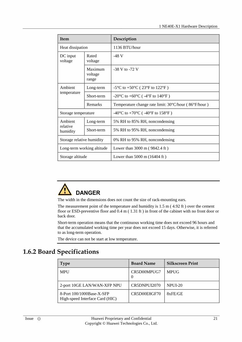
Item Description
Heat dissipation 1136 BTU/hour
DC input
voltage
Rated
voltage
-48 V
Maximum
voltage
range
-38 V to -72 V
Ambient
temperature
Long-term -5°C to +50°C ( 23°F to 122°F )
Short-term -20°C to +60°C ( -4°F to 140°F )
Remarks Temperature change rate limit: 30°C/hour ( 86°F/hour )
Storage temperature -40°C to +70°C ( -40°F to 158°F )
Ambient
relative
humidity
Long-term 5% RH to 85% RH, noncondensing
Short-term 5% RH to 95% RH, noncondensing
Storage relative humidity 0% RH to 95% RH, noncondensing
Long-term working altitude Lower than 3000 m ( 9842.4 ft )
Storage altitude Lower than 5000 m (16404 ft )
The width in the dimensions does not count the size of rack-mounting ears.
The measurement point of the temperature and humidity is 1.5 m ( 4.92 ft ) over the cement
floor or ESD-preventive floor and 0.4 m ( 1.31 ft ) in front of the cabinet with no front door or
back door.
Short-term operation means that the continuous working time does not exceed 96 hours and
that the accumulated working time per year does not exceed 15 days. Otherwise, it is referred
to as long-term operation.
The device can not be start at low temperature.
1.6.2 Board Specifications
Type Board Name Silkscreen Print
MPU CR5D00MPUG7
0
MPUG
2-port 10GE LAN/WAN-XFP NPU CR5DNPUI2070 NPUI-20
8-Port 100/1000Base-X-SFP
High-speed Interface Card (HIC)
CR5D00E8GF70 8xFE/GE

1 NE40E-X1 Hardware Description
Issue () Huawei Proprietary and Confidential
Copyright © Huawei Technologies Co., Ltd.
22
Type Board Name Silkscreen Print
8-Port 100/1000Base-X-SFP
High-speed Interface Card A
(HIC,Supporting 1588v2)
CR5D0E8GFA70 8xFE/GE-A
4-Port 100/1000Base-X-SFP
High-speed Interface Card(HIC)
CR5D00E4GF70 4xFE/GE
4-Port OC-3c/STM-1c POS-SFP
Flexible Interface Card(FIC)
CR5D00P4CF70 4xOC3-POS
8-Port 100Base-X-SFP Flexible
Interface Card (FIC,Supporting
1588v2)
CR5D00E8FF10 8xFE-SFP-A
8-Port 100Base-X-RJ45 Flexible
Interface Card (FIC,Supporting
1588v2)
CR5D00E8FE10 8xFE-RJ45A
16-Port E1 Flexible Interface
Card(FIC,75ohms)
CR5D000DE110 16xE1-75
16-Port E1 Flexible Interface
Card(FIC,120ohms)
CR5D000DE111 16xE1-120
Auxiliary Flexible Interface Card
with 4-Port 100Base-RJ45
(FIC,Supporting 1588v2)
CR5D00AUXQ1
0
AUX/4xFE-A
1-Port Channelized OC-3c/STM-1c
POS-SFP Flexible Interface Card
(FIC)
CR5D00C1CF10 1xOC3/cPOS
4-Port OC-3c/STM-1c ATM SFP
Flexible Interface Card (FIC)
CR5D00A4CF70 4×OC3c-ATM

2 NE40E-X2 Hardware Description
Issue () Huawei Proprietary and Confidential
Copyright © Huawei Technologies Co., Ltd.
23
2 NE40E-X2 Hardware Description
About This Chapter
2.1 Overview
2.2 Power Supply System
2.3 Heat Dissipation System
2.4 Data Plane
2.5 Control Plane
2.6 Physical Specifications
2.1 Overview
The NE40E-X2 is a high-end network device developed by Huawei. This device is based on
the VRP and applies to the access, convergence, and transmission of Metro Ethernet services.
The NE40E-X2 has great capabilities in network access, Layer 2 switching, and EoMPLS
transmission, and supports a wide range of high-speed and low-speed interfaces. Hence, the
NE40E-X2 supports triple-play of voice, video, and data services and can bear 2G/3G/LTE
services simultaneously. The NE40E-X2 can be deployed together with Huawei NE, CX, and
ME series products to build a Metro Ethernet network with a clear hierarchy and offer
extensive services. This chapter provides an overview of the hardware of the NE40E-X2.
2.1.1 Hardware Description
By adopting a centralized routing engine and NP forwarding structure, the NE40E-X2 has a
great capacity and can provide extensive services.
The NE40E-X2 adopts an integrated chassis that can be installed independently. The main
parts of the NE40E-X2 such as MPUs, NPUs, PICs, fan modules, and PSUs are
hot-swappable.
Figure 2-1 shows the outline of the NE40E-X2. The NE40E-X2 provides two slots for NPUs
and eight slots for PICs. The network process unit on the NE40E-X2 is NPUI-20. All the PICs
perform data switching through the NPUI-20. The NPUI-20 has a bidirectional processing
capability of up to 20 Gbit/s.

2 NE40E-X2 Hardware Description
Issue () Huawei Proprietary and Confidential
Copyright © Huawei Technologies Co., Ltd.
24
The maximum interface capacity of the NE40E-X2 is 75.2 Gbit/s.
Figure 2-1 Outline of the NE40E-X2
2.1.2 System Architecture
The logical architecture of the NE40E consists of the following planes: data plane, control and
management plane, and monitoring plane, as shown in Figure 2-2. The data plane processes
and switches data packets quickly and smoothly; the control and management plane, as the
core of the system, controls and manages the system; the monitoring plane monitors the
ambient operating conditions.

2 NE40E-X2 Hardware Description
Issue () Huawei Proprietary and Confidential
Copyright © Huawei Technologies Co., Ltd.
25
Figure 2-2 Diagram of the system architecture
Monitoring plane
Control and management plane
Data plane
MPU
NPUI Pic *N
Management unit
NPUI
Forwarding unit
System monitoring unit
MPU
Data channel
System monitoring unit
System monitoring unit
System monitoring unit
Management unit
PIC management unit
Forwarding unit
NE40E-X2 has two NPUI boards, and NE40E-X1 has only one NPUI board.
2.1.3 Main System Features
The main features of the system include:
NP-based forwarding which enables fast service deployment
Compact structure which increases the port density
Separation of the control channels, service channels, and monitoring channels, which
ensures the connectivity of control channels and monitoring channels
High-level carrier-class reliability and manageability
Module-level shielding which meets Electro Magnetic Compatibility (EMC)
requirements
Hot-swappable boards, PSUs, and fan modules
1:1 backup of MPUs
Backup for key parts such as PSUs, fan modules, clocks, and management buses
Protection against incorrect insertion of boards
Queries about alarm prompts, alarm indications, running status, and alarm status of PSUs
Queries about alarm prompts, alarm indications, running status, and alarm status of the
voltage and ambient temperature

2 NE40E-X2 Hardware Description
Issue () Huawei Proprietary and Confidential
Copyright © Huawei Technologies Co., Ltd.
26
2.1.4 System configuration
Table 2-1 System configuration list of the NE40E-X2
Item Description
Processing unit Main frequency: 1.3GHz
SDRAM 2 GB
Flash 32 MB
CF card 1 GB
Switching capacity 40 Gbit/s (bidirectional)
Interface capacity 75.2 Gbit/s
Number of NPU slots 2
Number of PIC slots 8
Number of MPU slots 2
Maximum port rate supported by PICs or NPUs 10 Gbit/s
2.1.5 Main Parts of the NE40E-X2
The NE40E-X2 adopts an integrated chassis, and the main parts of the NE40E-X2 are
hot-swappable.
Figure 2-3 shows the outline and parts of the NE40E-X2.

2 NE40E-X2 Hardware Description
Issue () Huawei Proprietary and Confidential
Copyright © Huawei Technologies Co., Ltd.
27
Figure 2-3 Outline and parts of the NE40E-X2
1. MPU 2. NPU 3. PIC 4. Cabling rack
5. PSU 6. Fan Module 7. Grounding
Terminal
8. Air intake
vent
9. Rack mounting
ear
10. Grounding
Terminal
11. ESD jack
2.1.6 Number of Main Parts and Slot Layout of the NE40E-X2
Figure 2-4 shows the slot layout of the NE40E-X2.
2 NE40E-X2 Hardware Description
Issue () Huawei Proprietary and Confidential
Copyright © Huawei Technologies Co., Ltd.
28
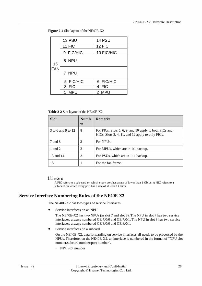
Figure 2-4 Slot layout of the NE40E-X2
15
FAN
13 PSU 14 PSU
11 FIC 12 FIC
10 FIC/HIC9 FIC/HIC
8 NPU
7 NPU
5 FIC/HIC 6 FIC/HIC
4 FIC3 FIC
1 MPU 2 MPU
Table 2-2 Slot layout of the NE40E-X2
Slot Number
Remarks
3 to 6 and 9 to 12 8 For PICs. Slots 5, 6, 9, and 10 apply to both FICs and
HICs. Slots 3, 4, 11, and 12 apply to only FICs.
7 and 8 2 For NPUs.
1 and 2 2 For MPUs, which are in 1:1 backup.
13 and 14 2 For PSUs, which are in 1+1 backup.
15 1 For the fan frame.
A FIC refers to a sub-card on which every port has a rate of lower than 1 Gbit/s. A HIC refers to a
sub-card on which every port has a rate of at least 1 Gbit/s.
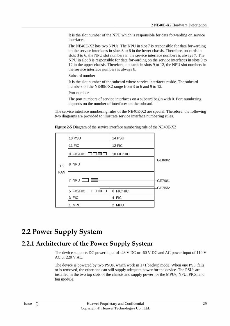
Service Interface Numbering Rules of the NE40E-X2
The NE40E-X2 has two types of service interfaces:
Service interfaces on an NPU
The NE40E-X2 has two NPUs (in slot 7 and slot 8). The NPU in slot 7 has two service
interfaces, always numbered GE 7/0/0 and GE 7/0/1. The NPU in slot 8 has two service
interfaces, always numbered GE 8/0/0 and GE 8/0/1.
Service interfaces on a subcard
On the NE40E-X2, data forwarding on service interfaces all needs to be processed by the
NPUs. Therefore, on the NE40E-X2, an interface is numbered in the format of "NPU slot
number/subcard number/port number".
− NPU slot number
2 NE40E-X2 Hardware Description
Issue () Huawei Proprietary and Confidential
Copyright © Huawei Technologies Co., Ltd.
29
It is the slot number of the NPU which is responsible for data forwarding on service
interfaces.
The NE40E-X2 has two NPUs. The NPU in slot 7 is responsible for data forwarding
on the service interfaces in slots 3 to 6 in the lower chassis. Therefore, on cards in
slots 3 to 6, the NPU slot numbers in the service interface numbers is always 7. The
NPU in slot 8 is responsible for data forwarding on the service interfaces in slots 9 to
12 in the upper chassis. Therefore, on cards in slots 9 to 12, the NPU slot numbers in
the service interface numbers is always 8.
− Subcard number
It is the slot number of the subcard where service interfaces reside. The subcard
numbers on the NE40E-X2 range from 3 to 6 and 9 to 12.
− Port number
The port numbers of service interfaces on a subcard begin with 0. Port numbering
depends on the number of interfaces on the subcard.
The service interface numbering rules of the NE40E-X2 are special. Therefore, the following
two diagrams are provided to illustrate service interface numbering rules.
Figure 2-5 Diagram of the service interface numbering rule of the NE40E-X2
15
FAN
13 PSU 14 PSU
11 FIC 12 FIC
10 FIC/HIC9 FIC/HIC
8 NPU
7 NPU
5 FIC/HIC 6 FIC/HIC
4 FIC3 FIC
1 MPU 2 MPU
GE7/0/1
GE8/9/2
GE7/5/2
2.2 Power Supply System
2.2.1 Architecture of the Power Supply System
The device supports DC power input of -48 V DC or -60 V DC and AC power input of 110 V
AC or 220 V AC.
The device is powered by two PSUs, which work in 1+1 backup mode. When one PSU fails
or is removed, the other one can still supply adequate power for the device. The PSUs are
installed in the two top slots of the chassis and supply power for the MPUs, NPU, PICs, and
fan module.
2 NE40E-X2 Hardware Description
Issue () Huawei Proprietary and Confidential
Copyright © Huawei Technologies Co., Ltd.
30
In the case of an AC power supply system, one AC power frames are placed outside the
chassis ( Huawei ETP48120-F1 is configured compliant to the standards ) and installed with
rectifier modules based on system power. The AC power frames are then connected to the
input terminals on the DC-PEMs to supply power for the system. (In short, external AC power
frames are added to the DC power supply system to constitute an AC power supply system.)
The following measures are taken to ensure that the PSUs can supply stable and safe power
for the system:
Protection against output overcurrent
Protection against output overvoltage
Protection against input undervoltage
Protection against overtemperature
Protection against short circuit
Alarm generation
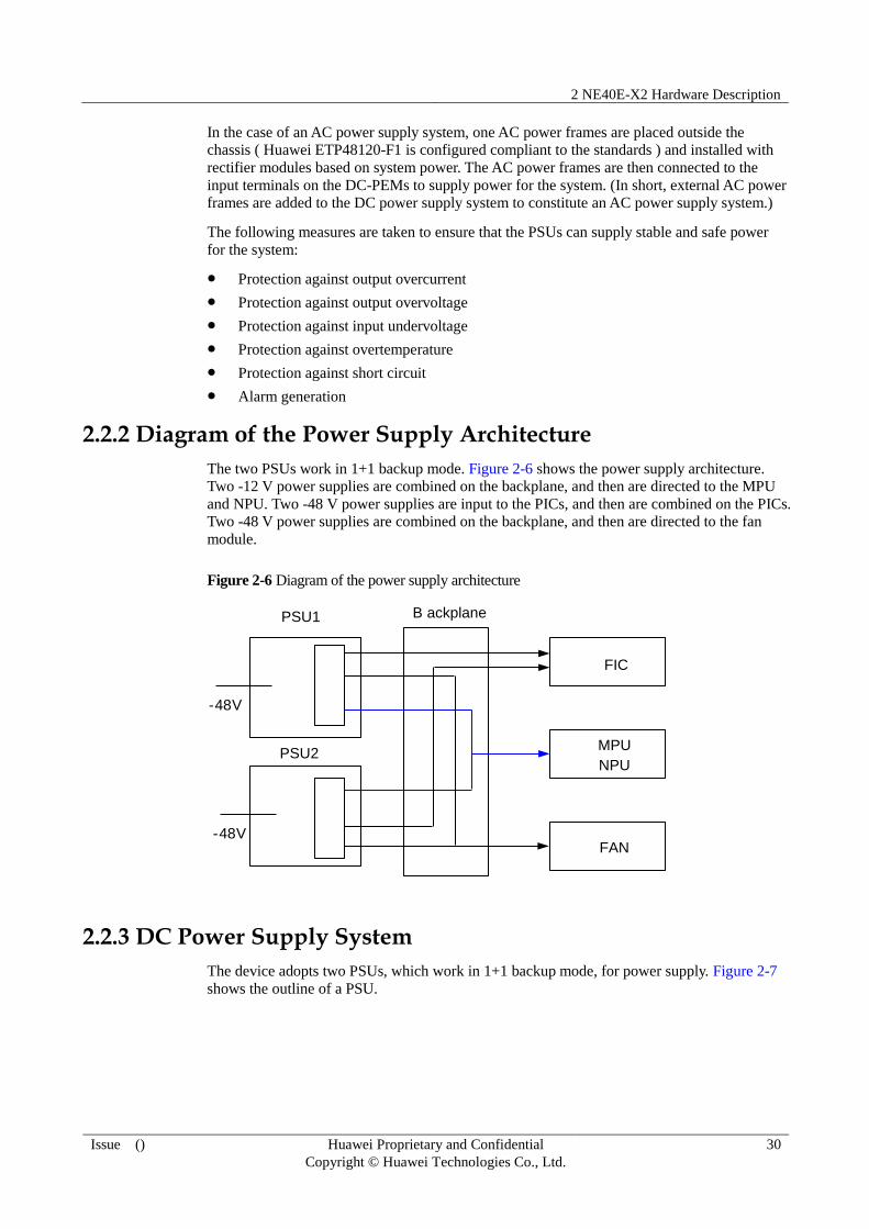
2.2.2 Diagram of the Power Supply Architecture
The two PSUs work in 1+1 backup mode. Figure 2-6 shows the power supply architecture.
Two -12 V power supplies are combined on the backplane, and then are directed to the MPU
and NPU. Two -48 V power supplies are input to the PICs, and then are combined on the PICs.
Two -48 V power supplies are combined on the backplane, and then are directed to the fan
module.
Figure 2-6 Diagram of the power supply architecture
PSU1
-48V
NPU
FAN
B ackplane
MPUPSU2
-48V
FIC
2.2.3 DC Power Supply System
The device adopts two PSUs, which work in 1+1 backup mode, for power supply. Figure 2-7
shows the outline of a PSU.

2 NE40E-X2 Hardware Description
Issue () Huawei Proprietary and Confidential
Copyright © Huawei Technologies Co., Ltd.
31
Figure 2-7 Outline of a PSU
Figure 2-8 shows the panel of a PSU.
Figure 2-8 Panel of a PSU
Table 2-3 Parameters of the PSUs
Item Parameter
Dimensions (W x D x H) 194 mm x 226 mm x 20 mm ( 7.64 in. x
8.90 in. x 0.79 in.)
Weight 1 kg ( 2.21 lb )
Rated voltage -48 V DC or -60 V DC
Input voltage range -38 V DC to -72 V DC
Maximum input current 24 A
Maximum output power 905 W
Table 2-4 Description of the indicators on the PSUs
Indicator Name Description
OUT When the indicator is steady green, it indicates that the PSUs work
normally and supply stable power.
When the indicator is steady red, it indicates that the hardware of
the PSUs fails or the device is not supplied with power ranging
from -48 V or -60 V.
When the indicator is off, it indicates that the PSUs are switched
off or the hardware of the PSUs is faulty.
IN When the indicator is steady green, it indicates that the power input

2 NE40E-X2 Hardware Description
Issue () Huawei Proprietary and Confidential
Copyright © Huawei Technologies Co., Ltd.
32
Indicator Name Description
is normal.
When the indicator is off, it indicates that the device is not supplied
with power ranging from -48 V or -60 V.
Notes on DC power monitoring:
The DC power monitoring channel can implement real-time monitoring on power supply.
In addition, the DC power monitoring channel allows you to query the manufacturing ID,
input voltage, and temperature of the PSUs in real time, and supports real-time reporting
of power supply alarms.
Notes on the configuration of DC power cables:
You do not need to connect protection ground cables to the PSUs, but the protection
ground cable for the chassis must be properly grounded. DC power cables include a -48
V power cable and a return (RTN) ground cable. The required cable length depends on
the distance between the cabinet and the power distribution cabinet for the device. The
DC power cables need to be prepared according to the required lengths on site. For
details of DC power cables see 4.1.1 DC Power Cables.
2.2.4 AC Power Supply System
Working principles of the ETP48120-F1 AC power supply system are as follows:
The ETP48120-F1 uses single-phase power input.
The ETP48120-F1 supplies power for AC-DC rectifiers using the system backplane.
The DC output of the AC-DC rectifiers is congregated by the bus and then divided to multiple
power-supplying channels.
The SMU01A monitoring module monitors the operating parameters of the ETP48120-F1 in
real time, analyzes the operating status, and reports alarms.
Figure 2-9 shows the outline of the ETP48120-F1 AC power supply system.
Figure 2-9 Outline of the ETP48120-F1 AC power supply system
Figure 2-10 shows the panel of the ETP48120-F1 AC power supply system.

2 NE40E-X2 Hardware Description
Issue () Huawei Proprietary and Confidential
Copyright © Huawei Technologies Co., Ltd.
33
Figure 2-10 Panel of the ETP48120-F1 AC power supply system
1. AC input
module
2. R4815G1 rectification
module (two)
3. SMU01A
monitoring module
4. PDM213 power
distribution module
Table 2-5 Parameters of the ETP48120-F1 AC power supply system
Item Parameter
Dimensions (W x D x H) 442 mm x 255 mm x 43.6 mm (17.40 in. x
10.04 in. x 1.72 in.)
Weight 7 kg (15.44 lb)
Rated voltage 100 V AC to 120 V AC (low-voltage)
200 V AC to 240 V AC (high-voltage)
Input voltage range 90 V AC to 276 V AC
Maximum input current 10 A
Maximum output power 870 W/single module
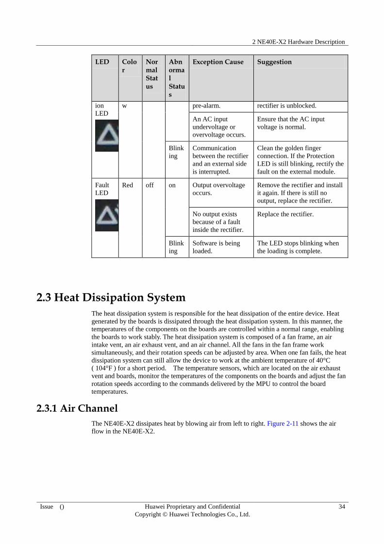
Table 2-6 LED Description of the rectification module
LED Color
Normal Status
Abnormal Status
Exception Cause Suggestion
Runni
ng
LED
Green on off No AC input exists. Ensure that the AC input
voltage is normal.
The input fuse is
damaged.
Replace the rectifier.
Blink
ing
Being queried
manually.
Exit the query state.
Protect Yello off on Overtemperature Ensure that the vent of the
2 NE40E-X2 Hardware Description
Issue () Huawei Proprietary and Confidential
Copyright © Huawei Technologies Co., Ltd.
34
LED Color
Normal Status
Abnormal Status
Exception Cause Suggestion
ion
LED
w pre-alarm. rectifier is unblocked.
An AC input
undervoltage or
overvoltage occurs.
Ensure that the AC input
voltage is normal.
Blink
ing
Communication
between the rectifier
and an external side
is interrupted.
Clean the golden finger
connection. If the Protection
LED is still blinking, rectify the
fault on the external module.
Fault
LED
Red off on Output overvoltage
occurs.
Remove the rectifier and install
it again. If there is still no
output, replace the rectifier.
No output exists
because of a fault
inside the rectifier.
Replace the rectifier.
Blink
ing
Software is being
loaded.
The LED stops blinking when
the loading is complete.
2.3 Heat Dissipation System
The heat dissipation system is responsible for the heat dissipation of the entire device. Heat
generated by the boards is dissipated through the heat dissipation system. In this manner, the
temperatures of the components on the boards are controlled within a normal range, enabling
the boards to work stably. The heat dissipation system is composed of a fan frame, an air
intake vent, an air exhaust vent, and an air channel. All the fans in the fan frame work
simultaneously, and their rotation speeds can be adjusted by area. When one fan fails, the heat
dissipation system can still allow the device to work at the ambient temperature of 40°C
( 104°F ) for a short period. The temperature sensors, which are located on the air exhaust
vent and boards, monitor the temperatures of the components on the boards and adjust the fan
rotation speeds according to the commands delivered by the MPU to control the board
temperatures.
2.3.1 Air Channel
The NE40E-X2 dissipates heat by blowing air from left to right. Figure 2-11 shows the air
flow in the NE40E-X2.

2 NE40E-X2 Hardware Description
Issue () Huawei Proprietary and Confidential
Copyright © Huawei Technologies Co., Ltd.
35
Figure 2-11 Air flow in the NE40E-X2
2.3.2 Fan Module
The air intake vent of the NE40E-X1 is 5 U ( 222.25 mm or 8.75 in. )high and 220 mm ( 8.66
in. ) deep.
There are nine fans in the fan frame of the NE40E-X1. When one fan fails, the device can still
work at the ambient temperature of 40°C ( 104°F ) for a short period.
The rotation speeds of the fans can be adjusted based on the device temperature.

2 NE40E-X2 Hardware Description
Issue () Huawei Proprietary and Confidential
Copyright © Huawei Technologies Co., Ltd.
36
Figure 2-12 Appearance of the fan module for the NE40E-X1
Figure 2-13 shows the panel of the fan module for the NE40E-X1.

2 NE40E-X2 Hardware Description
Issue () Huawei Proprietary and Confidential
Copyright © Huawei Technologies Co., Ltd.
37
Figure 2-13 Panel of the fan module for the NE40E-X1
Table 2-7 Technical specifications of the fan frame for the NE40E-X1
Parameter Value
Outline
dimension
(W * D * H)
50 mm x 226 mm x 219 mm ( 1.97 in. x 8.90 in. x 8.62 in. )
Weight 1.7 kg ( 3.75 lb )
Maximum
power
consumption
150W
Maximum
air pressure
477.2 Pa
Maximum
air volume
64.4 cubic feet per minute
Noise 64.3 dB

2 NE40E-X2 Hardware Description
Issue () Huawei Proprietary and Confidential
Copyright © Huawei Technologies Co., Ltd.
38
Table 2-8 Indicators on the fan module
Indicator Description
FAN indicator If the indicator is steady green, it indicates that the fan module
works normally.
The indicator is off when the fan module is unregistered, powered
off, or has a hardware fault.
If the indicator is steady red, it indicates that the fan module fails.
2.4 Data Plane
2.4.1 Introduction to the Data Plane
NPUs are key parts on the NE40E-X2 and are responsible for data processing and data
switching between PICs and NPUIs.
The procedure for data processing is as follows:
1. The IP packets sent from PICs and 2x10G interfaces on an NPU converge at a
convergence module.
2. The NP processes the IP packets.
3. The TM module performs traffic management on the IP packets.
4. The Fabric Interface Chip (FIC) performs IP packet switching.

2 NE40E-X2 Hardware Description
Issue () Huawei Proprietary and Confidential
Copyright © Huawei Technologies Co., Ltd.
39
Figure 2-14 Data plane architecture of the NE40E-X2
PHY
PIC 1
NPUI B
CPU Oversub
scribed
10GE
10GE
NPUI A
PHY
Interface
conversion
module
SFP
XFP
RJ45PIC 8
PHY
Interface
conversion
module
SFP
XFP
RJ45
Ba
ckp
lane
PHY
CPU Oversub
scribed
10GE
10GE
………
NPFIC TM
NPFIC TM
2.4.2 Introduction to the NPUI-20
The NPUI-20 has the bidirectional 20-Gbit/s forwarding capability, and all subcards switch
data through the NPUI-20,and NPUI-20 supporting 1588v2.
You can install two NPUs into the chassis of the NE40E-X2. The NPUI-20 in slot 7 is
connected to the PICs in slots 3, 4, 5, and 6. The NPUI-20 in slot 8 is connected to the PICs in
slots 9, 10, 11, and 12.

2 NE40E-X2 Hardware Description
Issue () Huawei Proprietary and Confidential
Copyright © Huawei Technologies Co., Ltd.
40
The NPUI-20 consists of the following planes:
Control and management plane
Through the management channels between MPUs and NPUI-20s, the MPUs can
manage NPUs and associated subcards, and transmit routing protocol data.
Data forwarding plane
The NPUI-20s are responsible for service processing in the entire system, and are
connected to all subcards through data channels.
An NPUI-20 provides two 10G Ethernet optical interfaces that can work in the WAN or
LAN mode and can be installed with XFP optical modules.
Table 2-9 NPUI-20 parameters
Item Description Remarks
Forwarding capability 20 Gbit/s (bidirectional) -
Interface Two 10GE XFP optical interfaces
that can work in the LAN or WAN
mode
-
Figure 2-15 Appearance of the NPUI-20 panel
1. Ejector lever 2. OFL indicator 3. OFL button 4. L/A1 indicator
5. Optical interface 6. L/A0 indicator 7. ACT indicator 8. STAT indicator
Table 2-10 describes the buttons and indicators on the NPU panel.
Table 2-10 Description of the buttons and indicators on the NPU panel
Indicator/Button
Description
STAT
indicator
If the indicator is steady green, it indicates that the NPUIworks normally.
If the indicator is steady red, it indicates that the hardware of the NPU is
faulty.
If the indicator blinks green, it indicates that NPU is being registered.
If the indicator is off, it indicates that the NPU is not powered on or fails to
be registered.
ACT If the indicator is steady green, it indicates that the NPU is in the master state.
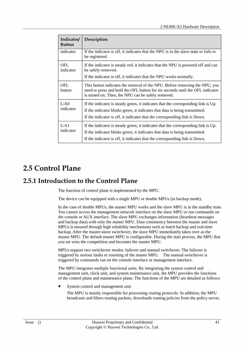
2 NE40E-X2 Hardware Description
Issue () Huawei Proprietary and Confidential
Copyright © Huawei Technologies Co., Ltd.
41
Indicator/Button
Description
indicator If the indicator is off, it indicates that the NPU is in the slave state or fails to
be registered.
OFL
indicator
If the indicator is steady red, it indicates that the NPU is powered off and can
be safely removed.
If the indicator is off, it indicates that the NPU works normally.
OFL
button
This button indicates the removal of the NPU. Before removing the NPU, you
need to press and hold the OFL button for six seconds until the OFL indicator
is turned on. Then, the NPU can be safely removed.
L/A0
indicator
If the indicator is steady green, it indicates that the corresponding link is Up.
If the indicator blinks green, it indicates that data is being transmitted.
If the indicator is off, it indicates that the corresponding link is Down.
L/A1
indicator
If the indicator is steady green, it indicates that the corresponding link is Up.
If the indicator blinks green, it indicates that data is being transmitted.
If the indicator is off, it indicates that the corresponding link is Down.
2.5 Control Plane
2.5.1 Introduction to the Control Plane
The function of control plane is implemented by the MPU.
The device can be equipped with a single MPU or double MPUs (in backup mode).
In the case of double MPUs, the master MPU works and the slave MPU is in the standby state.
You cannot access the management network interface on the slave MPU or run commands on
the console or AUX interface. The slave MPU exchanges information (heartbeat messages
and backup data) with only the master MPU. Data consistency between the master and slave
MPUs is ensured through high reliability mechanisms such as batch backup and real-time
backup. After the master-slave switchover, the slave MPU immediately takes over as the
master MPU. The default master MPU is configurable. During the start process, the MPU that
you set wins the competition and becomes the master MPU.
MPUs support two switchover modes: failover and manual switchover. The failover is
triggered by serious faults or resetting of the master MPU. The manual switchover is
triggered by commands run on the console interface or management interface.
The MPU integrates multiple functional units. By integrating the system control and
management unit, clock unit, and system maintenance unit, the MPU provides the functions
of the control plane and maintenance plane. The functions of the MPU are detailed as follows:
System control and management unit
The MPU is mainly responsible for processing routing protocols. In addition, the MPU
broadcasts and filters routing packets, downloads routing policies from the policy server.

2 NE40E-X2 Hardware Description
Issue () Huawei Proprietary and Confidential
Copyright © Huawei Technologies Co., Ltd.
42
The MPU manages the NPUs and communicates with the NPUs. The MPU implements
outband communication between boards. The MPU manages and carries out
communication between the NPUs and slave MPU through the outband management
bus.
The MPU is also responsible for data management. The system configuration data,
booting file, upgrade software, and system logs are stored on the MPU. The Compact
Flash (CF) card on the MPU functions as a mass storage device for saving data files
including system files, configuration files, and logs, and is not hot-swappable.
The MPU manages and maintains the device. Through management interfaces such as
serial interfaces and network interfaces on the MPU, you can manage and maintain the
device.
System clock unit
The system clock unit of the MPU provides NPUs and PICs with reliable and
synchronous SDH clock signals.
The MPUs supports the clock that complies with IEEE 1588v2.
System maintenance unit
The system maintenance unit of the MPU collects monitoring information, remotely or
locally tests system units, or performs in-service upgrade of system units.
Through the Monitorbus, the MPU collects the operation data periodically. The MPU
produces controlling information, such as detecting the board presence and adjusting the
fan speed.
The MPUs work in 1:1 hot backup mode, improving system reliability.
2.5.2 MPUG
Figure 2-16 shows the MPUG panel.
Figure 2-16 Appearance of the MPUG panel
1. USB indicator 2. USB interface 3. RS-485 interface 4. BITS clock
interface
5. Console interface 6. AUX
interface
7. ETH LINK
indicator
8. ETH interface
9. ETH ACT
indicator
10. RST button 11. ACT indicator 12. STAT indicator

2 NE40E-X2 Hardware Description
Issue () Huawei Proprietary and Confidential
Copyright © Huawei Technologies Co., Ltd.
43
Table 2-11 Description of the buttons and indicators on the MPUG panel
Indicator/Button
Description
STAT indicator If the indicator is steady green, it indicates that the MPUG works
normally.
If the indicator blinks green, it indicates that the MPUG is being
registered.
If the indicator is steady red, it indicates that the hardware of the
MPUG is faulty.
If the indicator is off, it indicates that the MPUG is not powered on or
fails to be registered.
ACT indicator If the indicator is steady green, it indicates that the MPUG functions as
the master MPU.
If the indicator is off, it indicates that the MPUG functions as the slave
MPU or is not registered.
USB indicator If the indicator is steady green, it indicates that a mobile storage
device is identified.
If the indicator blinks green, it indicates that a mobile storage device is
being accessed or written.
If the indicator is steady red, it indicates that a mobile storage device
cannot be identified or fails to be accessed or written.
If the indicator is off, it indicates that no mobile storage device is
connected to the USB interface.
ETH LINK
indicator
If the indicator is steady green, it indicates that the ETH link is Up.
If the indicator is off, it indicates that the ETH link is Down.
ETH ACT
indicator
If the indicator blinks yellow, it indicates that data is being
transmitted.
If the indicator is off, it indicates that no data is being transmitted.
RST button The button is used for resetting the MPUG. Pressing the RST button
resets the MPUG.
Table 2-12 Interfaces on the MPUG
Interface Name
Interface Type Description
ETH interface
(10M/100M/10
00M Base-TX
auto-sensing)
RJ45 One ETH interface, for system maintenance
Console
interface
RJ45 One console interface, used to connect to
the console for on-site configuration
AUX interface RJ45 One AUX interface, used to connect to the
modem for remote maintenance through a

2 NE40E-X2 Hardware Description
Issue () Huawei Proprietary and Confidential
Copyright © Huawei Technologies Co., Ltd.
44
Interface Name
Interface Type Description
dial-up connection
USB interface USB 2.0 One USB interface (USB 2.0 host interface),
for software upgrade
BITS clock
interface
RJ45 Two RJ45 interfaces. It is used to input or
output 2-Mbit/s clock signals, 2-MHz clock
signals, 1pps+ASCII clock signals, or two
channels of DCLS clock signals.
RS485
interface
RJ45 Used to connect to the monitoring interface
on the external AC power supply module
Attributes of the interfaces on the MPUG
Table 2-13 lists the USB interface attributes.
Table 2-13 Attributes of the USB interface
Attribute Description
Connector type USB
Working mode High-speed or full-speed
Standard
compliance
USB 2.0
Table 2-14 lists the 10Base-T/100Base-TX/1000Base-T-RJ45 interface attributes.
Table 2-14 Attributes of the 10Base-T/100Base-TX/1000Base-T-RJ45 interface
Attribute Description
Connector type RJ45
Working mode 10M/100M/1000M auto-sensing, half-duplex or full-duplex
Standard
compliance
IEEE 802.3-2002
Cable
specification
Super category 5 Shielded Twisted Pair (STP) cables recommended in
the case of 1000 Mbit/s
Table 2-15 lists the console interface attributes.

2 NE40E-X2 Hardware Description
Issue () Huawei Proprietary and Confidential
Copyright © Huawei Technologies Co., Ltd.
45
Table 2-15 Attributes of the console interface
Attribute Description
Connector type RJ45
Working mode Duplex Universal Asynchronous Receiver/Transmitter (UART)
Electrical
characteristics
RS-232
Baud rate 9600 bit/s (default value), which is configurable
Data equipment
type
Data Circuit-terminating Equipment (DCE)
Cable
specification
8-core shielded cable
Table 2-16 lists the AUX interface attributes.
Table 2-16 Attributes of the AUX interface
Attribute Description
Connector type RJ45
Working mode Duplex UART
Electrical
characteristics
RS-232
Baud rate 9600 bit/s (default value), which is configurable
Data equipment
type
DTE (Data Terminal Equipment)
Cable
specification
8-core shielded cable
Table 2-17 lists the external clock interface attributes.
Table 2-17 Attributes of the external clock interface
Attribute Description
Connector type RJ45
Cable
specification
120-ohm clock cable
Standard
compliance
G.703
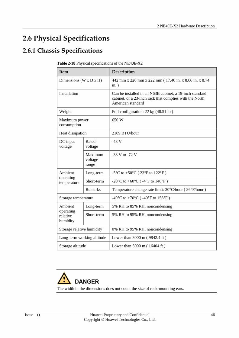
2 NE40E-X2 Hardware Description
Issue () Huawei Proprietary and Confidential
Copyright © Huawei Technologies Co., Ltd.
46
2.6 Physical Specifications
2.6.1 Chassis Specifications
Table 2-18 Physical specifications of the NE40E-X2
Item Description
Dimensions (W x D x H) 442 mm x 220 mm x 222 mm ( 17.40 in. x 8.66 in. x 8.74
in. )
Installation Can be installed in an N63B cabinet, a 19-inch standard
cabinet, or a 23-inch rack that complies with the North
American standard
Weight Full configuration: 22 kg (48.51 lb )
Maximum power
consumption
650 W
Heat dissipation 2109 BTU/hour
DC input
voltage
Rated
voltage
-48 V
Maximum
voltage
range
-38 V to -72 V
Ambient
operating
temperature
Long-term -5°C to +50°C ( 23°F to 122°F )
Short-term -20°C to +60°C ( -4°F to 140°F )
Remarks Temperature change rate limit: 30°C/hour ( 86°F/hour )
Storage temperature -40°C to +70°C ( -40°F to 158°F )
Ambient
operating
relative
humidity
Long-term 5% RH to 85% RH, noncondensing
Short-term 5% RH to 95% RH, noncondensing
Storage relative humidity 0% RH to 95% RH, noncondensing
Long-term working altitude Lower than 3000 m ( 9842.4 ft )
Storage altitude Lower than 5000 m ( 16404 ft )
The width in the dimensions does not count the size of rack-mounting ears.
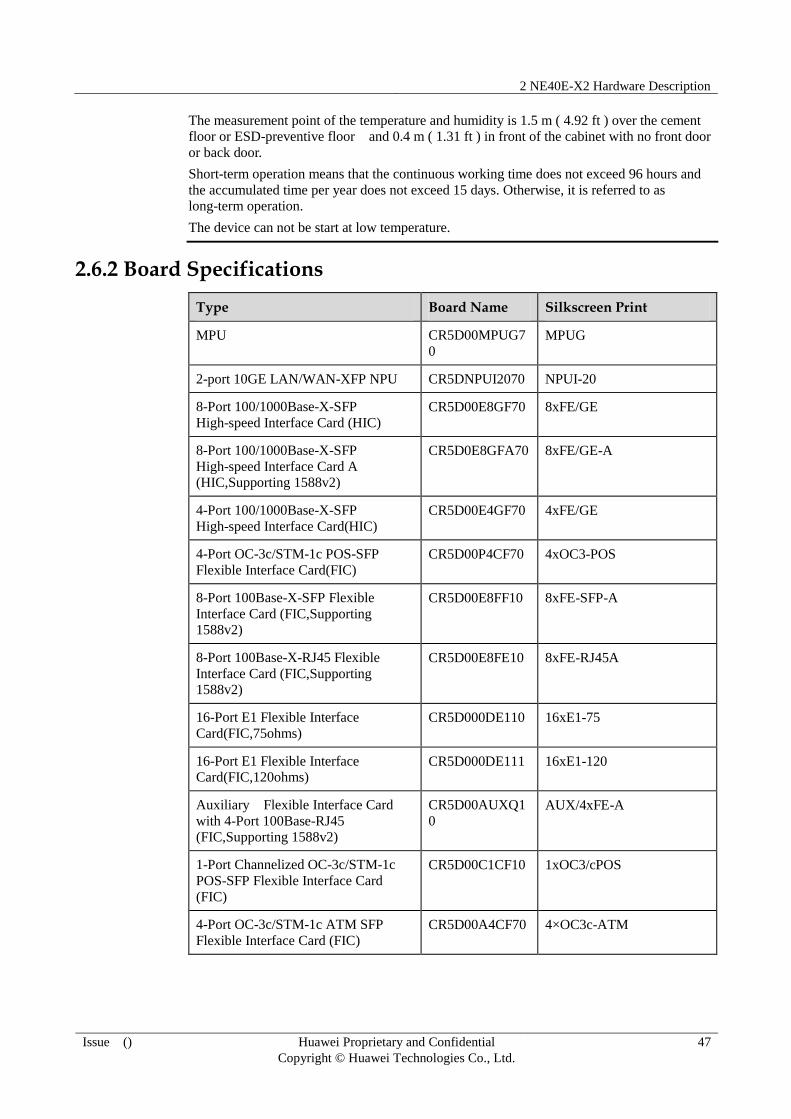
2 NE40E-X2 Hardware Description
Issue () Huawei Proprietary and Confidential
Copyright © Huawei Technologies Co., Ltd.
47
The measurement point of the temperature and humidity is 1.5 m ( 4.92 ft ) over the cement
floor or ESD-preventive floor and 0.4 m ( 1.31 ft ) in front of the cabinet with no front door
or back door.
Short-term operation means that the continuous working time does not exceed 96 hours and
the accumulated time per year does not exceed 15 days. Otherwise, it is referred to as
long-term operation.
The device can not be start at low temperature.
2.6.2 Board Specifications
Type Board Name Silkscreen Print
MPU CR5D00MPUG7
0
MPUG
2-port 10GE LAN/WAN-XFP NPU CR5DNPUI2070 NPUI-20
8-Port 100/1000Base-X-SFP
High-speed Interface Card (HIC)
CR5D00E8GF70 8xFE/GE
8-Port 100/1000Base-X-SFP
High-speed Interface Card A
(HIC,Supporting 1588v2)
CR5D0E8GFA70 8xFE/GE-A
4-Port 100/1000Base-X-SFP
High-speed Interface Card(HIC)
CR5D00E4GF70 4xFE/GE
4-Port OC-3c/STM-1c POS-SFP
Flexible Interface Card(FIC)
CR5D00P4CF70 4xOC3-POS
8-Port 100Base-X-SFP Flexible
Interface Card (FIC,Supporting
1588v2)
CR5D00E8FF10 8xFE-SFP-A
8-Port 100Base-X-RJ45 Flexible
Interface Card (FIC,Supporting
1588v2)
CR5D00E8FE10 8xFE-RJ45A
16-Port E1 Flexible Interface
Card(FIC,75ohms)
CR5D000DE110 16xE1-75
16-Port E1 Flexible Interface
Card(FIC,120ohms) CR5D000DE111 16xE1-120
Auxiliary Flexible Interface Card
with 4-Port 100Base-RJ45
(FIC,Supporting 1588v2)
CR5D00AUXQ1
0
AUX/4xFE-A
1-Port Channelized OC-3c/STM-1c
POS-SFP Flexible Interface Card
(FIC)
CR5D00C1CF10 1xOC3/cPOS
4-Port OC-3c/STM-1c ATM SFP
Flexible Interface Card (FIC)
CR5D00A4CF70 4×OC3c-ATM

3 Boards
Issue () Huawei Proprietary and Confidential
Copyright © Huawei Technologies Co., Ltd.
48
3 Boards
About This Chapter
This chapter describes the boards of the device.
3.1 8-Port 100/1000Base-X-SFP High-speed Interface Card (HIC)
3.2 8-Port 100/1000Base-X-SFP High-speed Interface Card A (HIC, Supporting 1588v2)
3.3 4-Port 100/1000Base-X-SFP High-speed Interface Card(HIC)
3.4 4-Port OC-3c/STM-1c POS-SFP Flexible Interface Card (FIC)
3.5 8-Port 100Base-X-SFP Flexible Interface Card (FIC, Supporting 1588v2)
3.6 8-Port 100Base-RJ45 Flexible Interface Card (FIC, Supporting 1588v2)
3.7 16-Port E1(75ohm) Flexible Interface Card (FIC)
3.8 16-Port E1(120ohm) Flexible Interface Card (FIC)
3.9 Auxiliary Flexible Interface Card with 4-Port 100Base-RJ45(FIC, Supporting 1588v2)
3.10 1-Port Channelized OC3c/STM1c POS-SFP Flexible Interface Card (FIC)
3.11 4-Port OC-3c/STM-1c ATM SFP Flexible Interface Card (FIC)
3.1 8-Port 100/1000Base-X-SFP High-speed Interface Card (HIC)
Overview
The 8-Port 100/1000Base-X-SFP High-speed Interface Card (HIC)supports synchronization
Ethernet and the following types of optical modules:
GE optical module, providing features of GE optical interfaces
FE optical module, providing features of FE optical interfaces
Electrical-interface SFP module, providing features of 100M/1000M auto-sensing
electrical interfaces When the 8-Port 100/1000Base-X-SFP High-speed Interface Card
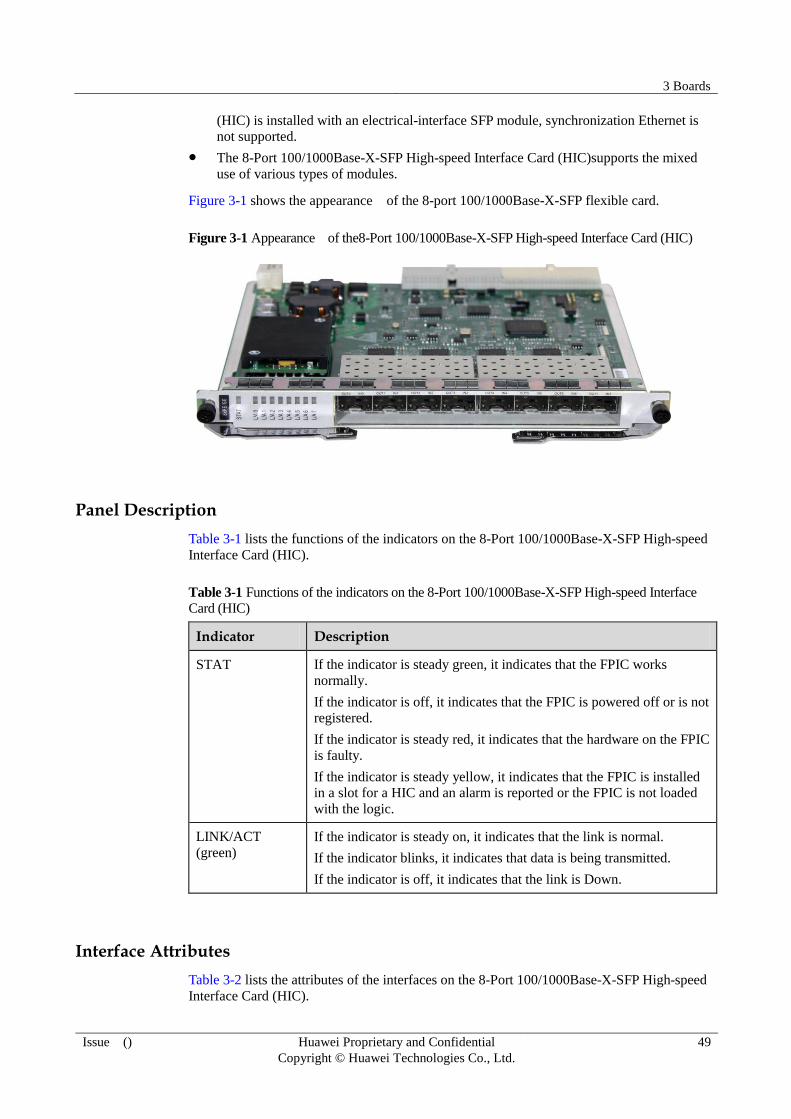
3 Boards
Issue () Huawei Proprietary and Confidential
Copyright © Huawei Technologies Co., Ltd.
49
(HIC) is installed with an electrical-interface SFP module, synchronization Ethernet is
not supported.
The 8-Port 100/1000Base-X-SFP High-speed Interface Card (HIC)supports the mixed
use of various types of modules.
Figure 3-1 shows the appearance of the 8-port 100/1000Base-X-SFP flexible card.
Figure 3-1 Appearance of the8-Port 100/1000Base-X-SFP High-speed Interface Card (HIC)
Panel Description
Table 3-1 lists the functions of the indicators on the 8-Port 100/1000Base-X-SFP High-speed
Interface Card (HIC).
Table 3-1 Functions of the indicators on the 8-Port 100/1000Base-X-SFP High-speed Interface
Card (HIC)
Indicator Description
STAT If the indicator is steady green, it indicates that the FPIC works
normally.
If the indicator is off, it indicates that the FPIC is powered off or is not
registered.
If the indicator is steady red, it indicates that the hardware on the FPIC
is faulty.
If the indicator is steady yellow, it indicates that the FPIC is installed
in a slot for a HIC and an alarm is reported or the FPIC is not loaded
with the logic.
LINK/ACT
(green)
If the indicator is steady on, it indicates that the link is normal.
If the indicator blinks, it indicates that data is being transmitted.
If the indicator is off, it indicates that the link is Down.
Interface Attributes
Table 3-2 lists the attributes of the interfaces on the 8-Port 100/1000Base-X-SFP High-speed
Interface Card (HIC).

3 Boards
Issue () Huawei Proprietary and Confidential
Copyright © Huawei Technologies Co., Ltd.
50
Table 3-2 Attributes of the interfaces on the 8-Port 100/1000Base-X-SFP High-speed Interface
Card (HIC)
Attribute Value
Connector LC/PC
Interface
attributes Determined by the selected SFP optical module
Working mode Full-duplex
Standard
compliance
IEEE 802.3-2002
Frame format Ethernet_II, Ethernet_SAP, and Ethernet_SNAP
Network protocol IP
Table 3-3 Attributes of the 100 M SFP optical module
Attribute Value
Maximum
transmission
distance
2 km ( 1.24
mi. )
15 km ( 9.32
mi. )
40 km ( 24.86
mi. )
80 km ( 49.71
mi. )
Center wavelength 1310 nm 1310 nm 1310 nm 1550 nm
Minimum output
power
-19.0 dBm -15.0 dBm -5.0 dBm -5.0 dBm
Maximum output
power
-14.0 dBm -8.0 dBm 0 dBm 0 dBm
Receiver sensitivity -30.0 dBm -31.0 dBm -37.0 dBm -37.0 dBm
Overload optical
power
-14.0 dBm -8.0 dBm -10.0 dBm -10.0 dBm
Fiber type Multimode Single-mode Single-mode Single-mode
Table 3-4 Attributes of 1000M SFP optical modules
Attribute Value
Transmission
Distance
0.5 km
( 0.31
mi. )
10 km
( 6.21
mi. )
40 km
( 24.86
mi. )
40 km
( 24.86
mi. )
80 km
( 49.71
mi. )
100 km
( 62.14
mi. )
Center
wavelength
850 nm 1310 nm 1310 nm 1550 nm 1550
nm
1550 nm
Minimum output
power -9.5 dBm -9.5 dBm -4.5 dBm -4.0 dBm -2.0
dBm 0 dBm
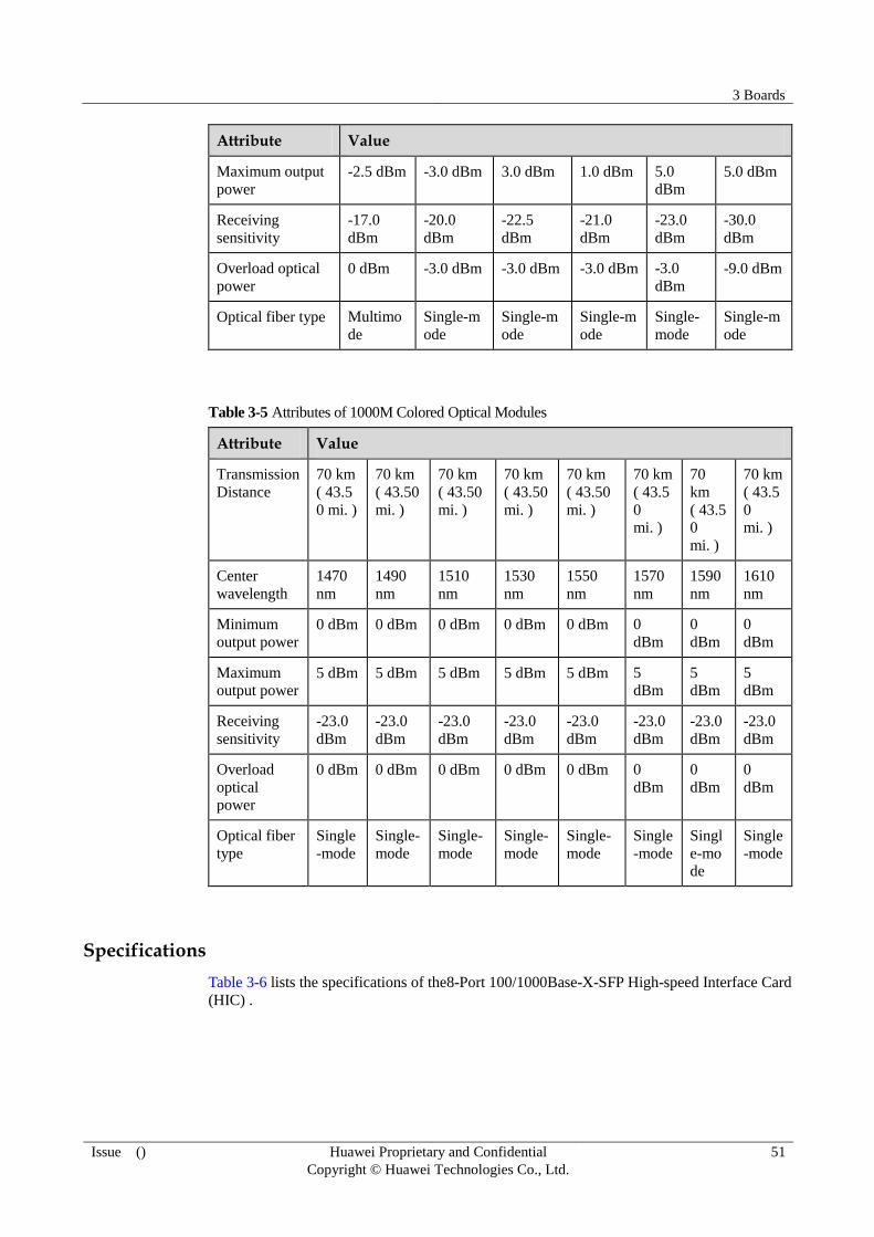
3 Boards
Issue () Huawei Proprietary and Confidential
Copyright © Huawei Technologies Co., Ltd.
51
Attribute Value
Maximum output
power
-2.5 dBm -3.0 dBm 3.0 dBm 1.0 dBm 5.0
dBm
5.0 dBm
Receiving
sensitivity
-17.0
dBm
-20.0
dBm
-22.5
dBm
-21.0
dBm
-23.0
dBm
-30.0
dBm
Overload optical
power
0 dBm -3.0 dBm -3.0 dBm -3.0 dBm -3.0
dBm
-9.0 dBm
Optical fiber type Multimo
de
Single-m
ode
Single-m
ode
Single-m
ode
Single-
mode
Single-m
ode
Table 3-5 Attributes of 1000M Colored Optical Modules
Attribute Value
Transmission
Distance
70 km
( 43.5
0 mi. )
70 km
( 43.50
mi. )
70 km
( 43.50
mi. )
70 km
( 43.50
mi. )
70 km
( 43.50
mi. )
70 km
( 43.5
0
mi. )
70
km
( 43.5
0
mi. )
70 km
( 43.5
0
mi. )
Center
wavelength
1470
nm
1490
nm
1510
nm
1530
nm
1550
nm
1570
nm
1590
nm
1610
nm
Minimum
output power
0 dBm 0 dBm 0 dBm 0 dBm 0 dBm 0
dBm
0
dBm
0
dBm
Maximum
output power 5 dBm 5 dBm 5 dBm 5 dBm 5 dBm 5
dBm
5
dBm
5
dBm
Receiving
sensitivity
-23.0
dBm
-23.0
dBm
-23.0
dBm
-23.0
dBm
-23.0
dBm
-23.0
dBm
-23.0
dBm
-23.0
dBm
Overload
optical
power
0 dBm 0 dBm 0 dBm 0 dBm 0 dBm 0
dBm
0
dBm
0
dBm
Optical fiber
type
Single
-mode
Single-
mode
Single-
mode
Single-
mode
Single-
mode
Single
-mode
Singl
e-mo
de
Single
-mode
Specifications
Table 3-6 lists the specifications of the8-Port 100/1000Base-X-SFP High-speed Interface Card
(HIC) .
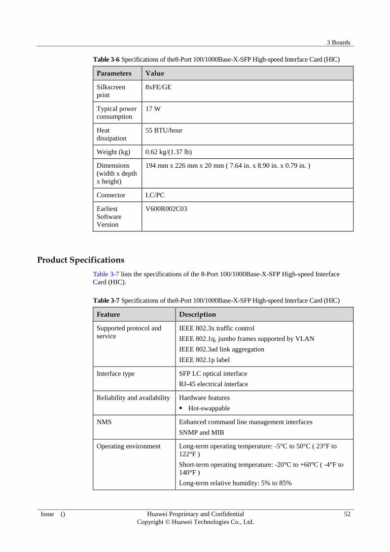
3 Boards
Issue () Huawei Proprietary and Confidential
Copyright © Huawei Technologies Co., Ltd.
52
Table 3-6 Specifications of the8-Port 100/1000Base-X-SFP High-speed Interface Card (HIC)
Parameters Value
Silkscreen
8xFE/GE
Typical power
consumption 17 W
Heat
dissipation
55 BTU/hour
Weight (kg) 0.62 kg/(1.37 lb)
Dimensions
(width x depth
x height)
194 mm x 226 mm x 20 mm ( 7.64 in. x 8.90 in. x 0.79 in. )
Connector LC/PC
Earliest
Software
Version
V600R002C03
Product Specifications
Table 3-7 lists the specifications of the 8-Port 100/1000Base-X-SFP High-speed Interface
Card (HIC).
Table 3-7 Specifications of the8-Port 100/1000Base-X-SFP High-speed Interface Card (HIC)
Feature Description
Supported protocol and
service
IEEE 802.3x traffic control
IEEE 802.1q, jumbo frames supported by VLAN
IEEE 802.3ad link aggregation
IEEE 802.1p label
Interface type SFP LC optical interface
RJ-45 electrical interface
Reliability and availability Hardware features
Hot-swappable
NMS Enhanced command line management interfaces
SNMP and MIB
Operating environment Long-term operating temperature: -5°C to 50°C ( 23°F to
122°F )
Short-term operating temperature: -20°C to +60°C ( -4°F to
140°F )
Long-term relative humidity: 5% to 85%
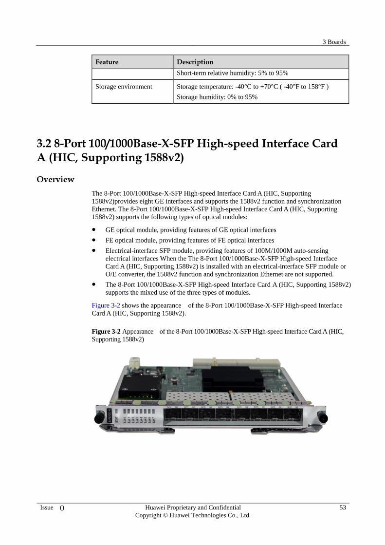
3 Boards
Issue () Huawei Proprietary and Confidential
Copyright © Huawei Technologies Co., Ltd.
53
Feature Description
Short-term relative humidity: 5% to 95%
Storage environment Storage temperature: -40°C to +70°C ( -40°F to 158°F )
Storage humidity: 0% to 95%
3.2 8-Port 100/1000Base-X-SFP High-speed Interface Card A (HIC, Supporting 1588v2)
Overview
The 8-Port 100/1000Base-X-SFP High-speed Interface Card A (HIC, Supporting
1588v2)provides eight GE interfaces and supports the 1588v2 function and synchronization
Ethernet. The 8-Port 100/1000Base-X-SFP High-speed Interface Card A (HIC, Supporting
1588v2) supports the following types of optical modules:
GE optical module, providing features of GE optical interfaces
FE optical module, providing features of FE optical interfaces
Electrical-interface SFP module, providing features of 100M/1000M auto-sensing
electrical interfaces When the The 8-Port 100/1000Base-X-SFP High-speed Interface
Card A (HIC, Supporting 1588v2) is installed with an electrical-interface SFP module or
O/E converter, the 1588v2 function and synchronization Ethernet are not supported.
The 8-Port 100/1000Base-X-SFP High-speed Interface Card A (HIC, Supporting 1588v2)
supports the mixed use of the three types of modules.
Figure 3-2 shows the appearance of the 8-Port 100/1000Base-X-SFP High-speed Interface
Card A (HIC, Supporting 1588v2).
Figure 3-2 Appearance of the 8-Port 100/1000Base-X-SFP High-speed Interface Card A (HIC,
Supporting 1588v2)

3 Boards
Issue () Huawei Proprietary and Confidential
Copyright © Huawei Technologies Co., Ltd.
54
Panel Description
Table 3-8 lists the functions of the indicators on the 8-Port 100/1000Base-X-SFP High-speed
Interface Card A (HIC, Supporting 1588v2).
Table 3-8 Functions of the indicators on the8-Port 100/1000Base-X-SFP High-speed Interface
Card A (HIC, Supporting 1588v2)
Indicator Meaning
STAT If the indicator is steady green, it indicates that the FPIC works
normally.
If the indicator is off, it indicates that the FPIC is powered off or is not
registered.
If the indicator is steady red, it indicates that the hardware on the FPIC
is faulty.
If the indicator is steady yellow, it indicates that the HIC is installed in
a slot for a FIC and an alarm is reported or the FPIC is not loaded with
the logic.
LINK/ACT
(green)
If the indicator is steady green, it indicates that links are Up.
If the indicator blinks, it indicates that data is being transmitted.
If the indicator is off, it indicates that the link is Down.
Interface Attributes
Table 3-9 lists the attributes of the interfaces on the 8-Port 100/1000Base-X-SFP High-speed
Interface Card A (HIC, Supporting 1588v2).
Table 3-9 Attributes of the interfaces on the 8-Port 100/1000Base-X-SFP High-speed Interface
Card A (HIC, Supporting 1588v2)
Attribute Value
Connector LC/PC
Interface
attributes
Determined by the selected SFP optical module
Working mode Full-duplex
Standard
compliance
IEEE 802.3-2002
Frame format Ethernet_II, Ethernet_SAP, and Ethernet_SNAP
Network protocol IP

3 Boards
Issue () Huawei Proprietary and Confidential
Copyright © Huawei Technologies Co., Ltd.
55
Table 3-10 Attributes of the 100 M SFP optical module
Attribute Value
Maximum
transmission
distance
2 km ( 1.24
mi. )
15 km ( 9.32
mi. )
40 km ( 24.86
mi. )
80 km ( 49.71
mi. )
Center wavelength 1310 nm 1310 nm 1310 nm 1550 nm
Minimum output
power
-19.0 dBm -15.0 dBm -5.0 dBm -5.0 dBm
Maximum output
power
-14.0 dBm -8.0 dBm 0 dBm 0 dBm
Receiver sensitivity -30.0 dBm -31.0 dBm -37.0 dBm -37.0 dBm
Overload optical
power
-14.0 dBm -8.0 dBm -10.0 dBm -10.0 dBm
Fiber type Multimode Single-mode Single-mode Single-mode
Table 3-11 Attributes of the 1000M SFP optical module
Attribute Value
Transmission
Distance
0.5 km
( 0.31
mi. )
10 km
( 6.21
mi. )
40 km
( 24.86
mi. )
40 km
( 24.86
mi. )
80 km
( 49.71
mi. )
100 km
( 62.14
mi. )
Center
wavelength
850 nm 1310 nm 1310 nm 1550 nm 1550
nm
1550 nm
Minimum output
power
-9.5 dBm -9.5 dBm -4.5 dBm -4.0 dBm -2.0
dBm
0 dBm
Maximum output
power
-2.5 dBm -3.0 dBm 3.0 dBm 1.0 dBm 5.0
dBm
5.0 dBm
Receiving
sensitivity
-17.0
dBm
-20.0
dBm
-22.5
dBm
-21.0
dBm
-23.0
dBm
-30.0
dBm
Overload optical
power
0 dBm -3.0 dBm -3.0 dBm -3.0 dBm -3.0
dBm
-9.0 dBm
Optical fiber type Multimo
de
Single-m
ode
Single-m
ode
Single-m
ode
Single-
mode
Single-m
ode
Table 3-12 Attributes of the 1000M colored optical module
Attribute Value
Transmission
distance
70 km
( 43.5
70 km
( 43.50
70 km
( 43.50
70 km
( 43.50
70 km
( 43.50
70 km
( 43.5
70
km
70 km
( 43.5
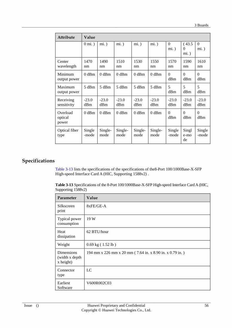
3 Boards
Issue () Huawei Proprietary and Confidential
Copyright © Huawei Technologies Co., Ltd.
56
Attribute Value
0 mi. ) mi. ) mi. ) mi. ) mi. ) 0
mi. )
( 43.5
0
mi. )
0
mi. )
Center
wavelength
1470
nm
1490
nm
1510
nm
1530
nm
1550
nm
1570
nm
1590
nm
1610
nm
Minimum
output power
0 dBm 0 dBm 0 dBm 0 dBm 0 dBm 0
dBm
0
dBm
0
dBm
Maximum
output power
5 dBm 5 dBm 5 dBm 5 dBm 5 dBm 5
dBm
5
dBm
5
dBm
Receiving
sensitivity
-23.0
dBm
-23.0
dBm
-23.0
dBm
-23.0
dBm
-23.0
dBm
-23.0
dBm
-23.0
dBm
-23.0
dBm
Overload
optical
power
0 dBm 0 dBm 0 dBm 0 dBm 0 dBm 0
dBm
0
dBm
0
dBm
Optical fiber
type
Single
-mode
Single-
mode
Single-
mode
Single-
mode
Single-
mode
Single
-mode
Singl
e-mo
de
Single
-mode
Specifications
Table 3-13 lists the specifications of the specifications of the8-Port 100/1000Base-X-SFP
High-speed Interface Card A (HIC, Supporting 1588v2) .
Table 3-13 Specifications of the 8-Port 100/1000Base-X-SFP High-speed Interface Card A (HIC,
Supporting 1588v2)
Parameter Value
Silkscreen
8xFE/GE-A
Typical power
consumption
19 W
Heat
dissipation
62 BTU/hour
Weight 0.69 kg ( 1.52 lb )
Dimensions
(width x depth
x height)
194 mm x 226 mm x 20 mm ( 7.64 in. x 8.90 in. x 0.79 in. )
Connector
type
LC
Earliest
Software
V600R002C03

3 Boards
Issue () Huawei Proprietary and Confidential
Copyright © Huawei Technologies Co., Ltd.
57
Parameter Value
Version
Product Specifications
Table 3-14 lists the specifications of the 8-Port 100/1000Base-X-SFP High-speed Interface
Card A (HIC, Supporting 1588v2).
Table 3-14 Product specifications of the 8-Port 100/1000Base-X-SFP High-speed Interface Card
A (HIC, Supporting 1588v2)
Model Value
Supported protocol and
service
IEEE 802.3x traffic control
IEEE 802.1q jumbo frames supported by VLAN
IEEE 802.3ad link aggregation
IEEE 802.1p label
1588v2
Interface type SFP LC optical interface
RJ-45 electrical interface
Reliability and availability Hardware features
Hot-swap
NMS Enhanced command line management interfaces
SNMP and MIB
Operating environment Long-term operating temperature: -5°C to 50°C ( 23°F to
122°F )
Short-term operating temperature: -20°C to +60°C ( -4°F to
140°F )
Long-term relative humidity: 5% to 85%
Short-term relative humidity: 5% to 95%
Storage environment Storage temperature: -40°C to +70°C ( -40°F to 158°F )
Storage humidity: 0% to 95%
3.3 4-Port 100/1000Base-X-SFP High-speed Interface Card(HIC)
Overview
4-Port 100/1000Base-X-SFP High-speed Interface Card(HIC) supports the following types of
optical modules:
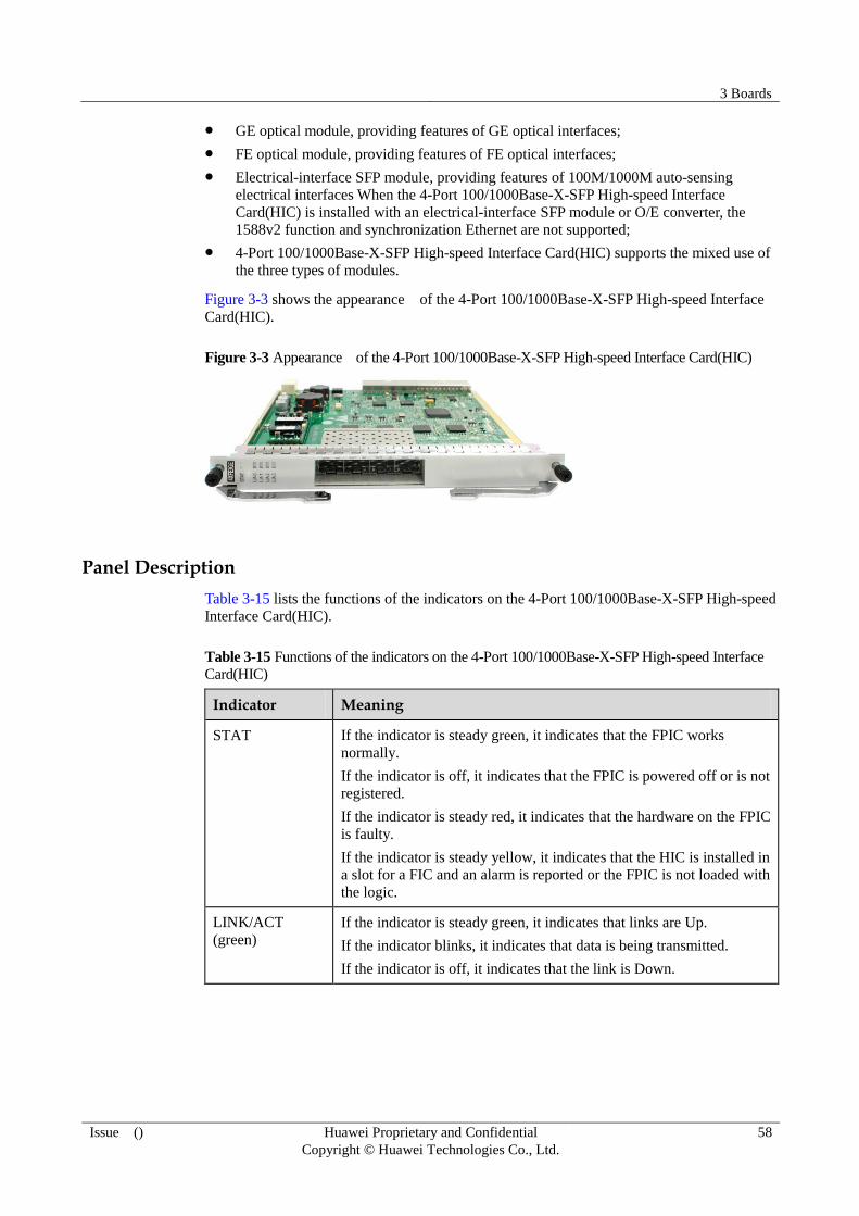
3 Boards
Issue () Huawei Proprietary and Confidential
Copyright © Huawei Technologies Co., Ltd.
58
GE optical module, providing features of GE optical interfaces;
FE optical module, providing features of FE optical interfaces;
Electrical-interface SFP module, providing features of 100M/1000M auto-sensing
electrical interfaces When the 4-Port 100/1000Base-X-SFP High-speed Interface
Card(HIC) is installed with an electrical-interface SFP module or O/E converter, the
1588v2 function and synchronization Ethernet are not supported;
4-Port 100/1000Base-X-SFP High-speed Interface Card(HIC) supports the mixed use of
the three types of modules.
Figure 3-3 shows the appearance of the 4-Port 100/1000Base-X-SFP High-speed Interface
Card(HIC).
Figure 3-3 Appearance of the 4-Port 100/1000Base-X-SFP High-speed Interface Card(HIC)
Panel Description
Table 3-15 lists the functions of the indicators on the 4-Port 100/1000Base-X-SFP High-speed
Interface Card(HIC).
Table 3-15 Functions of the indicators on the 4-Port 100/1000Base-X-SFP High-speed Interface
Card(HIC)
Indicator Meaning
STAT If the indicator is steady green, it indicates that the FPIC works
normally.
If the indicator is off, it indicates that the FPIC is powered off or is not
registered.
If the indicator is steady red, it indicates that the hardware on the FPIC
is faulty.
If the indicator is steady yellow, it indicates that the HIC is installed in
a slot for a FIC and an alarm is reported or the FPIC is not loaded with
the logic.
LINK/ACT
(green)
If the indicator is steady green, it indicates that links are Up.
If the indicator blinks, it indicates that data is being transmitted.
If the indicator is off, it indicates that the link is Down.

3 Boards
Issue () Huawei Proprietary and Confidential
Copyright © Huawei Technologies Co., Ltd.
59
Interface Attributes
Table 3-16 lists the attributes of the interfaces on the 4-Port 100/1000Base-X-SFP High-speed
Interface Card(HIC).
Table 3-16 Attributes of the interfaces on the 4-Port 100/1000Base-X-SFP High-speed Interface
Card(HIC)
Attribute Value
Connector LC/PC
Interface
attributes
Determined by the selected SFP optical module
Working mode Full-duplex
Standard
compliance
IEEE 802.3-2002
Frame format Ethernet_II, Ethernet_SAP, and Ethernet_SNAP
Network protocol IP
Table 3-17 Attributes of the 100 M SFP optical module
Attribute Value
Maximum
transmission
distance
2 km ( 1.24
mi. )
15 km ( 9.32
mi. )
40 km ( 24.86
mi. )
80 km ( 49.71
mi. )
Center wavelength 1310 nm 1310 nm 1310 nm 1550 nm
Minimum output
power
-19.0 dBm -15.0 dBm -5.0 dBm -5.0 dBm
Maximum output
power
-14.0 dBm -8.0 dBm 0 dBm 0 dBm
Receiver sensitivity -30.0 dBm -31.0 dBm -37.0 dBm -37.0 dBm
Overload optical
power
-14.0 dBm -8.0 dBm -10.0 dBm -10.0 dBm
Fiber type Multimode Single-mode Single-mode Single-mode
Table 3-18 Attributes of the 1000M SFP optical module
Attribute Value
Transmission
Distance
0.5 km
( 0.31
mi. )
10 km
( 6.21
mi. )
40 km
( 24.86
mi. )
40 km
( 24.86
mi. )
80 km
( 49.71
mi. )
100 km
( 62.14
mi. )
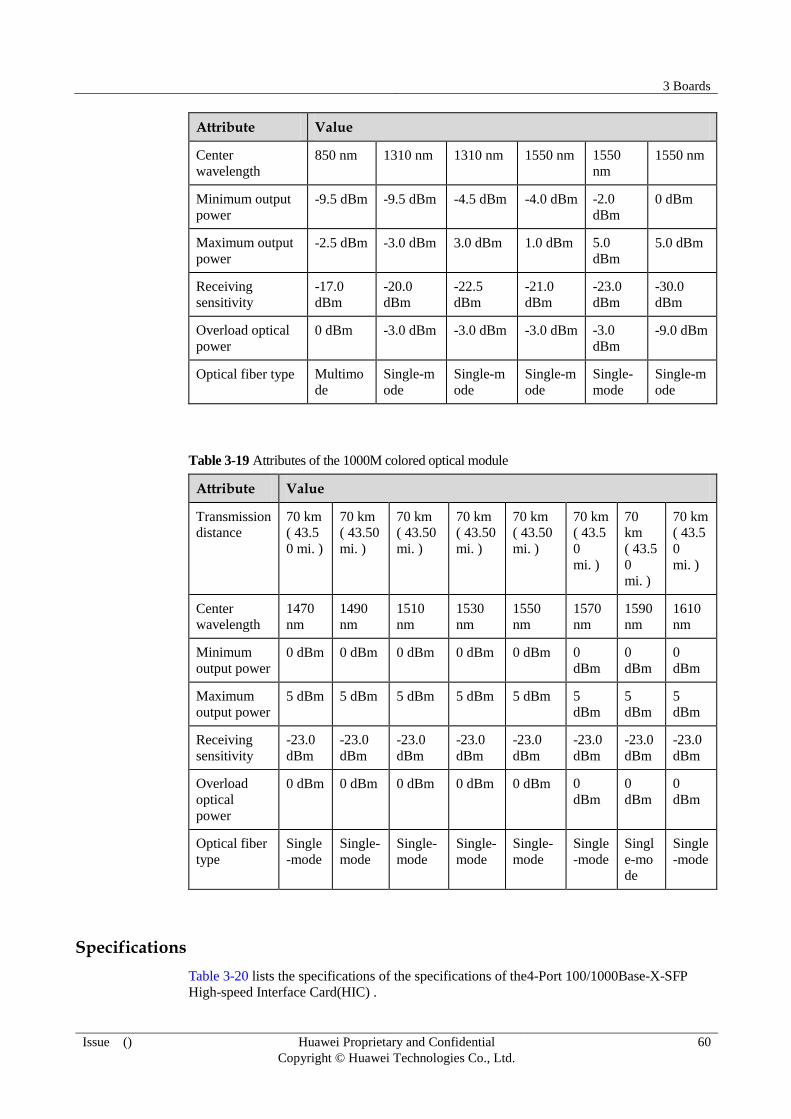
3 Boards
Issue () Huawei Proprietary and Confidential
Copyright © Huawei Technologies Co., Ltd.
60
Attribute Value
Center
wavelength
850 nm 1310 nm 1310 nm 1550 nm 1550
nm
1550 nm
Minimum output
power
-9.5 dBm -9.5 dBm -4.5 dBm -4.0 dBm -2.0
dBm
0 dBm
Maximum output
power
-2.5 dBm -3.0 dBm 3.0 dBm 1.0 dBm 5.0
dBm
5.0 dBm
Receiving
sensitivity
-17.0
dBm
-20.0
dBm
-22.5
dBm
-21.0
dBm
-23.0
dBm
-30.0
dBm
Overload optical
power
0 dBm -3.0 dBm -3.0 dBm -3.0 dBm -3.0
dBm
-9.0 dBm
Optical fiber type Multimo
de
Single-m
ode
Single-m
ode
Single-m
ode
Single-
mode
Single-m
ode
Table 3-19 Attributes of the 1000M colored optical module
Attribute Value
Transmission
distance
70 km
( 43.5
0 mi. )
70 km
( 43.50
mi. )
70 km
( 43.50
mi. )
70 km
( 43.50
mi. )
70 km
( 43.50
mi. )
70 km
( 43.5
0
mi. )
70
km
( 43.5
0
mi. )
70 km
( 43.5
0
mi. )
Center
wavelength
1470
nm
1490
nm
1510
nm
1530
nm
1550
nm
1570
nm
1590
nm
1610
nm
Minimum
output power
0 dBm 0 dBm 0 dBm 0 dBm 0 dBm 0
dBm
0
dBm
0
dBm
Maximum
output power
5 dBm 5 dBm 5 dBm 5 dBm 5 dBm 5
dBm
5
dBm
5
dBm
Receiving
sensitivity
-23.0
dBm
-23.0
dBm
-23.0
dBm
-23.0
dBm
-23.0
dBm
-23.0
dBm
-23.0
dBm
-23.0
dBm
Overload
optical
power
0 dBm 0 dBm 0 dBm 0 dBm 0 dBm 0
dBm
0
dBm
0
dBm
Optical fiber
type
Single
-mode
Single-
mode
Single-
mode
Single-
mode
Single-
mode
Single
-mode
Singl
e-mo
de
Single
-mode
Specifications
Table 3-20 lists the specifications of the specifications of the4-Port 100/1000Base-X-SFP
High-speed Interface Card(HIC) .

3 Boards
Issue () Huawei Proprietary and Confidential
Copyright © Huawei Technologies Co., Ltd.
61
Table 3-20 Specifications of the 4-Port 100/1000Base-X-SFP High-speed Interface Card(HIC)
Parameter Value
Silkscreen
4xFE/GE
Typical power
consumption 12.8 W
Heat
dissipation
41.53 BTU/hour
Weight 0.575 kg ( 1.27 lb )
Dimensions
(width x depth
x height)
194 mm x 226 mm x 20 mm ( 7.64 in. x 8.90 in. x 0.79 in. )
Connector
type
LC
Earliest
Software
Version
V600R005C00
Product Specifications
Table 3-21 lists the specifications of the 4-Port 100/1000Base-X-SFP High-speed Interface
Card(HIC).
Table 3-21 Product specifications of the 4-Port 100/1000Base-X-SFP High-speed Interface
Card(HIC)
Model Value
Supported protocol and
service
IEEE 802.3x traffic control
IEEE 802.1q jumbo frames supported by VLAN
IEEE 802.3ad link aggregation
IEEE 802.1p label
Interface type SFP LC optical interface
Reliability and availability Hardware features
Hot-swap
NMS Enhanced command line management interfaces
SNMP and MIB
Operating environment Long-term operating temperature: -5°C to 50°C ( 23°F to
122°F )
Short-term operating temperature: -20°C to +60°C ( -4°F to
140°F )
Long-term relative humidity: 5% to 85%

3 Boards
Issue () Huawei Proprietary and Confidential
Copyright © Huawei Technologies Co., Ltd.
62
Model Value
Short-term relative humidity: 5% to 95%
Storage environment Storage temperature: -40°C to +70°C ( -40°F to 158°F )
Storage humidity: 0% to 95%
3.4 4-Port OC-3c/STM-1c POS-SFP Flexible Interface Card (FIC)
Overview
Figure 3-4 shows the appearance of the 4-Port OC-3c/STM-1c POS-SFP Flexible Interface
Card (FIC).
Figure 3-4 4-Port OC-3c/STM-1c POS-SFP Flexible Interface Card (FIC)
Panel Description
Table 3-22 describes the indicators on the 4-Port OC-3c/STM-1c POS-SFP Flexible Interface
Card (FIC).
Table 3-22 Indicators on the 4-Port OC-3c/STM-1c POS-SFP Flexible Interface Card (FIC)
Indicator Description
STAT If the indicator is steady green, the 4-Port OC-3c/STM-1c POS-SFP
Flexible Interface Card (FIC) is working properly.
If the indicator is steady off, the 4-Port OC-3c/STM-1c POS-SFP
Flexible Interface Card (FIC) does not register or is powered off.
If the indicator is steady red, the 4-Port OC-3c/STM-1c POS-SFP
Flexible Interface Card (FIC) has hardware faults.
If the indicator is steady yellow, no logic is loaded to the 4-Port
OC-3c/STM-1c POS-SFP Flexible Interface Card (FIC).
LINK/ACT
(green)
If the indicator is steady on, the link is working properly.
If the indicator blinks, data is being transmitted.
If the indicator is steady off, the link is not working properly.

3 Boards
Issue () Huawei Proprietary and Confidential
Copyright © Huawei Technologies Co., Ltd.
63
Interface attributes
Table 3-23 lists the interface attributes of the 4-Port OC-3c/STM-1c POS-SFP Flexible
Interface Card (FIC).
Table 3-23 Interface attributes of the 4-Port OC-3c/STM-1c POS-SFP Flexible Interface Card
(FIC)
Attribute Description
Connector type LC/PC
Interface attribute Determined by the selected SFP optical module
Working mode Full-duplex
Link protocol PPP, HDLC
Supported
network protocol
IP
Table 3-24 Attributes of the 155 M SFP optical module
Attribute Description
Maximum
transmission
distance
2 km ( 1.24 mi. ) 15 km ( 9.32
mi. )
40 km ( 24.86
mi. )
80 km ( 49.71
mi. )
Center
wavelength
1310 nm 1310 nm 1310 nm 1550 nm
Minimum
transmit optical
power
-19.0 dBm -15.0 dBm -5.0 dBm -5.0 dBm
Maximum
transmit optical
power
-14.0 dBm -8.0 dBm 0 dBm 0 dBm
Receiver
sensitivity
-30.0 dBm -31.0 dBm -37.0 dBm -37.0 dBm
Overload
optical power -14.0 dBm -8.0 dBm -10.0 dBm -10.0 dBm
Fiber mode Multi-mode Single-mode Single-mode Single-mode
Technical Specifications
Table 3-25 lists the technical specifications of the4-Port OC-3c/STM-1c POS-SFP Flexible
Interface Card (FIC).
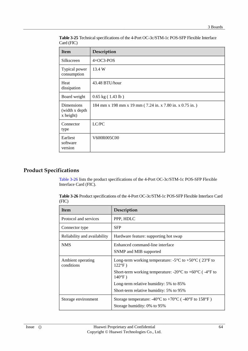
3 Boards
Issue () Huawei Proprietary and Confidential
Copyright © Huawei Technologies Co., Ltd.
64
Table 3-25 Technical specifications of the 4-Port OC-3c/STM-1c POS-SFP Flexible Interface
Card (FIC)
Item Description
Silkscreen 4×OC3-POS
Typical power
consumption 13.4 W
Heat
dissipation
43.48 BTU/hour
Board weight 0.65 kg ( 1.43 lb )
Dimensions
(width x depth
x height)
184 mm x 198 mm x 19 mm ( 7.24 in. x 7.80 in. x 0.75 in. )
Connector
type
LC/PC
Earliest
software
version
V600R005C00
Product Specifications
Table 3-26 lists the product specifications of the 4-Port OC-3c/STM-1c POS-SFP Flexible
Interface Card (FIC).
Table 3-26 Product specifications of the 4-Port OC-3c/STM-1c POS-SFP Flexible Interface Card
(FIC)
Item Description
Protocol and services PPP, HDLC
Connector type SFP
Reliability and availability Hardware feature: supporting hot swap
NMS Enhanced command-line interface
SNMP and MIB supported
Ambient operating
conditions
Long-term working temperature: -5°C to +50°C ( 23°F to
122°F )
Short-term working temperature: -20°C to +60°C ( -4°F to
140°F )
Long-term relative humidity: 5% to 85%
Short-term relative humidity: 5% to 95%
Storage environment Storage temperature: -40°C to +70°C ( -40°F to 158°F )
Storage humidity: 0% to 95%

3 Boards
Issue () Huawei Proprietary and Confidential
Copyright © Huawei Technologies Co., Ltd.
65
3.5 8-Port 100Base-X-SFP Flexible Interface Card (FIC, Supporting 1588v2)
Overview
The 8-Port 100Base-X-SFP Flexible Interface Card (FIC, Supporting 1588v2)has eight FE
optical interfaces.
The8-Port 100Base-X-SFP Flexible Interface Card (FIC, Supporting 1588v2)consists of an
access convergence module, a control drive module, a clock module, and a power supply
module.
Access convergence module
− Providing eight FE optical interfaces
− Supporting the cache function to avoid the loss of signals on the FE optical interface
− Supporting the flow control function for controlling the volume of packets
− Supporting the 1588v2 packet processing function
Control drive module
− Detecting the system status through the management and control bus
− Implementing the hot-swap function
Clock module
− Providing a working clock for each module
− Supporting synchronization Ethernet
− Supporting the IEEE 1588V2 protocol
Power supply module
− Supporting two -48V/-60V DC inputs
− Supplying 3.3 V and 1.2 V power
Figure 3-5 shows the appearance of the 8-Port 100Base-X-SFP Flexible Interface Card (FIC,
Supporting 1588v2).

3 Boards
Issue () Huawei Proprietary and Confidential
Copyright © Huawei Technologies Co., Ltd.
66
Figure 3-5 Appearance of the 8-Port 100Base-X-SFP Flexible Interface Card (FIC, Supporting
1588v2)
Panel Description
Table 3-27 lists the indicators on the 8-Port 100Base-X-SFP Flexible Interface Card (FIC,
Supporting 1588v2).
Table 3-27 Description of the indicators on the 8-Port 100Base-X-SFP Flexible Interface Card
(FIC, Supporting 1588v2)
Indicator/Button
Meaning
STAT If the indicator is steady green, it indicates that the FPIC works
normally.
If the indicator is off, it indicates that the FPIC is powered off or is not
registered.
If the indicator is steady red, it indicates that the hardware on the FPIC
is faulty.
If the indicator is steady yellow, it indicates that the FPIC is not
loaded with the logic.
LINK/ACT
(green)
If the indicator is steady green, it indicates that the FPIC works
normally.
If the indicator is off, it indicates that the link is Down.
Interface Attributes
Table 3-28 lists the interface attributes of the 8-Port 100Base-X-SFP Flexible Interface Card
(FIC, Supporting 1588v2).
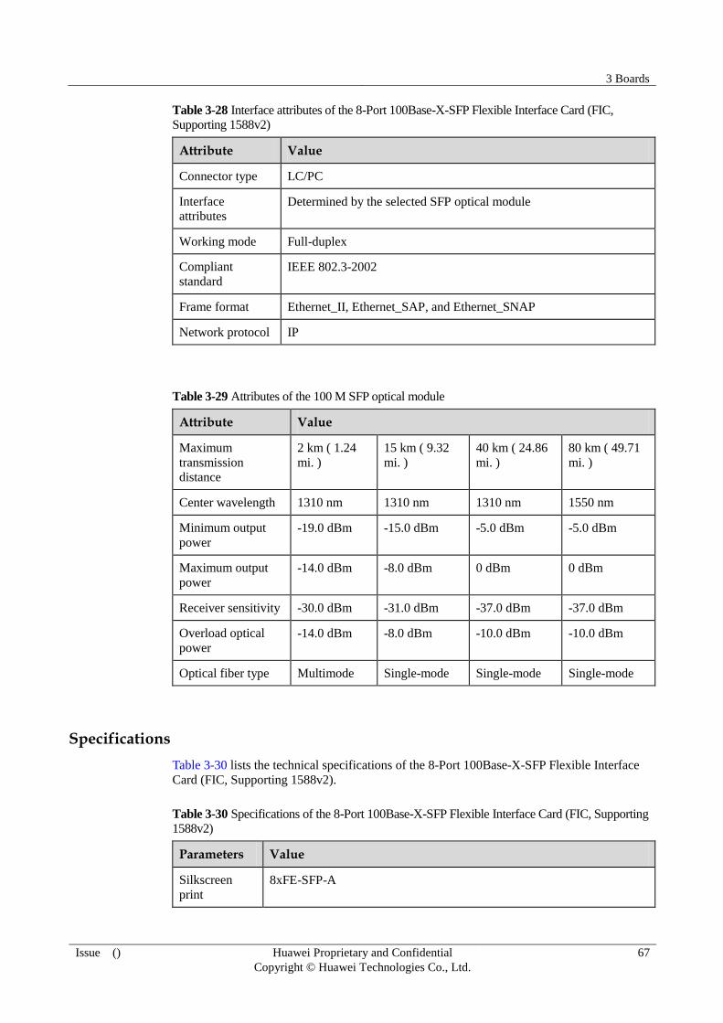
3 Boards
Issue () Huawei Proprietary and Confidential
Copyright © Huawei Technologies Co., Ltd.
67
Table 3-28 Interface attributes of the 8-Port 100Base-X-SFP Flexible Interface Card (FIC,
Supporting 1588v2)
Attribute Value
Connector type LC/PC
Interface
attributes Determined by the selected SFP optical module
Working mode Full-duplex
Compliant
standard
IEEE 802.3-2002
Frame format Ethernet_II, Ethernet_SAP, and Ethernet_SNAP
Network protocol IP
Table 3-29 Attributes of the 100 M SFP optical module
Attribute Value
Maximum
transmission
distance
2 km ( 1.24
mi. )
15 km ( 9.32
mi. )
40 km ( 24.86
mi. )
80 km ( 49.71
mi. )
Center wavelength 1310 nm 1310 nm 1310 nm 1550 nm
Minimum output
power
-19.0 dBm -15.0 dBm -5.0 dBm -5.0 dBm
Maximum output
power
-14.0 dBm -8.0 dBm 0 dBm 0 dBm
Receiver sensitivity -30.0 dBm -31.0 dBm -37.0 dBm -37.0 dBm
Overload optical
power
-14.0 dBm -8.0 dBm -10.0 dBm -10.0 dBm
Optical fiber type Multimode Single-mode Single-mode Single-mode
Specifications
Table 3-30 lists the technical specifications of the 8-Port 100Base-X-SFP Flexible Interface
Card (FIC, Supporting 1588v2).
Table 3-30 Specifications of the 8-Port 100Base-X-SFP Flexible Interface Card (FIC, Supporting
1588v2)
Parameters Value
Silkscreen
8xFE-SFP-A

3 Boards
Issue () Huawei Proprietary and Confidential
Copyright © Huawei Technologies Co., Ltd.
68
Parameters Value
Typical power
consumption
13 W
Heat
dissipation
42 BTU/hour
Weight 0.45 kg ( 0.99 lb )
Dimensions
(width x depth
x height)
194 mm x 226 mm x 20 mm ( 7.64 in. x 8.90 in. x 0.79 in. )
Connector
type
LC/PC
Earliest
Software
Version
V600R002C03
Product Specifications
Table 3-31 lists the specifications of the 8-Port 100Base-X-SFP Flexible Interface Card (FIC,
Supporting 1588v2).
Table 3-31 Specifications of the 8-Port 100Base-X-SFP Flexible Interface Card (FIC, Supporting
1588v2)
Feature Description
Supported protocol and
service
IEEE 802.3
Interface type SFP LC optical interface
Reliability and availability Hardware features
Hot-swappable
NMS Enhanced command line management interfaces
SNMP and MIB
Operating environment Long-term operating temperature: -5°C to 50°C ( 23°F to
122°F )
Short-term operating temperature: -20°C to +60°C ( -4°F to
140°F )
Long-term relative humidity: 5% to 85%
Short-term relative humidity: 5% to 95%
Storage environment Storage temperature: -40°C to +70°C ( -40°F to 158°F )
Storage humidity: 0% to 95%

3 Boards
Issue () Huawei Proprietary and Confidential
Copyright © Huawei Technologies Co., Ltd.
69
3.6 8-Port 100Base-RJ45 Flexible Interface Card (FIC, Supporting 1588v2)
Overview
The 8-Port 100Base-RJ45 Flexible Interface Card (FIC, Supporting 1588v2) has eight FE
interfaces for electrical signal access.
The 8-Port 100Base-RJ45 Flexible Interface Card (FIC, Supporting 1588v2)consists of an
access convergence module, control drive module, clock module, and power supply module.
Access convergence module
− Providing eight FE interfaces for electrical signal access
− Supporting the cache function to avoid the loss of signals on the FE interface
− Supporting the flow control function for controlling the volume of packets
− Supporting 1588v2 packet processing function
Control drive module
− Implementing the system status detection function through the management and
control bus
− Implementing the hot swap function
Clock module
− Providing a working clock for each module
− Supporting synchronization Ethernet
− Supporting IEEE 1588v2
Power supply module
− Supporting two -48V/-60V DC inputs
− Supplying 3.3 V and 1.2 V power for the card
Figure 3-6 shows the appearance of the 8-Port 100Base-RJ45 Flexible Interface Card (FIC,
Supporting 1588v2).
Figure 3-6 Appearance of the 8-Port 100Base-RJ45 Flexible Interface Card (FIC, Supporting
1588v2)

3 Boards
Issue () Huawei Proprietary and Confidential
Copyright © Huawei Technologies Co., Ltd.
70
Panel Description
Table 3-32 describes the indicators on the 8-Port 100Base-RJ45 Flexible Interface Card (FIC,
Supporting 1588v2).
Table 3-32 Indicators on the 8-Port 100Base-RJ45 Flexible Interface Card (FIC, Supporting
1588v2)
Indicator Meaning
STAT If the indicator is steady on, it indicates that the TND1EF8T works
normally.
If the indicator is off, it indicates that the TND1EF8T is not powered
on or fails to be registered.
If the indicator is steady red, it indicates that the hardware of the
TND1EF8T is faulty.
If the indicator is steady yellow, it indicates that the FPIC is not
loaded with the logic.
Interface Attributes
Table 3-33 lists the interface attributes of the 8-Port 100Base-RJ45 Flexible Interface Card
(FIC, Supporting 1588v2).
Table 3-33 Interface attributes of the 8-Port 100Base-RJ45 Flexible Interface Card (FIC,
Supporting 1588v2)
Attribute Value
Connector RJ45
Working mode Full-duplex
Standard
compliance
IEEE 802.3-2002
Frame format Ethernet_II, Ethernet_SAP, and Ethernet_SNAP
Network protocol IP
Specifications
Table 3-34 lists the technical specifications of the 8-Port 100Base-RJ45 Flexible Interface
Card (FIC, Supporting 1588v2).
Table 3-34 Specifications of the 8-Port 100Base-RJ45 Flexible Interface Card (FIC, Supporting
1588v2)
Parameters Value
Silkscreen 8xFE-RJ45A

3 Boards
Issue () Huawei Proprietary and Confidential
Copyright © Huawei Technologies Co., Ltd.
71
Parameters Value
Typical power
consumption
9 W
Heat
dissipation
29 BTU/hour
Weight 0.43 kg ( 0.95 lb )
Dimensions
(width x depth
x height)
194 mm x 226 mm x 20 mm ( 7.64 in. x 8.90 in. x 0.79 in. )
Connector RJ-45
Earliest
software
version
V600R002C03
Product Specifications
Table 3-35 lists the specifications of the 8-Port 100Base-RJ45 Flexible Interface Card (FIC,
Supporting 1588v2).
Table 3-35 Specifications of the 8-Port 100Base-RJ45 Flexible Interface Card (FIC, Supporting
1588v2)
Feature Description
Supported protocol and
service
IEEE 802.3
Interface type RJ-45
Reliability and availability Hardware features
Hot-swappable
NMS Enhanced command line management interfaces
SNMP and MIB
Operating environment Long-term operating temperature: -5°C to 50°C ( 23°F to
122°F )
Short-term operating temperature: -20°C to +60°C (-4°F to
140°F )
Long-term relative humidity: 5% to 85%
Short-term relative humidity: 5% to 95%
Storage environment Storage temperature: -40°C to +70°C ( -40°F to 158°F )
Storage humidity: 0% to 95%
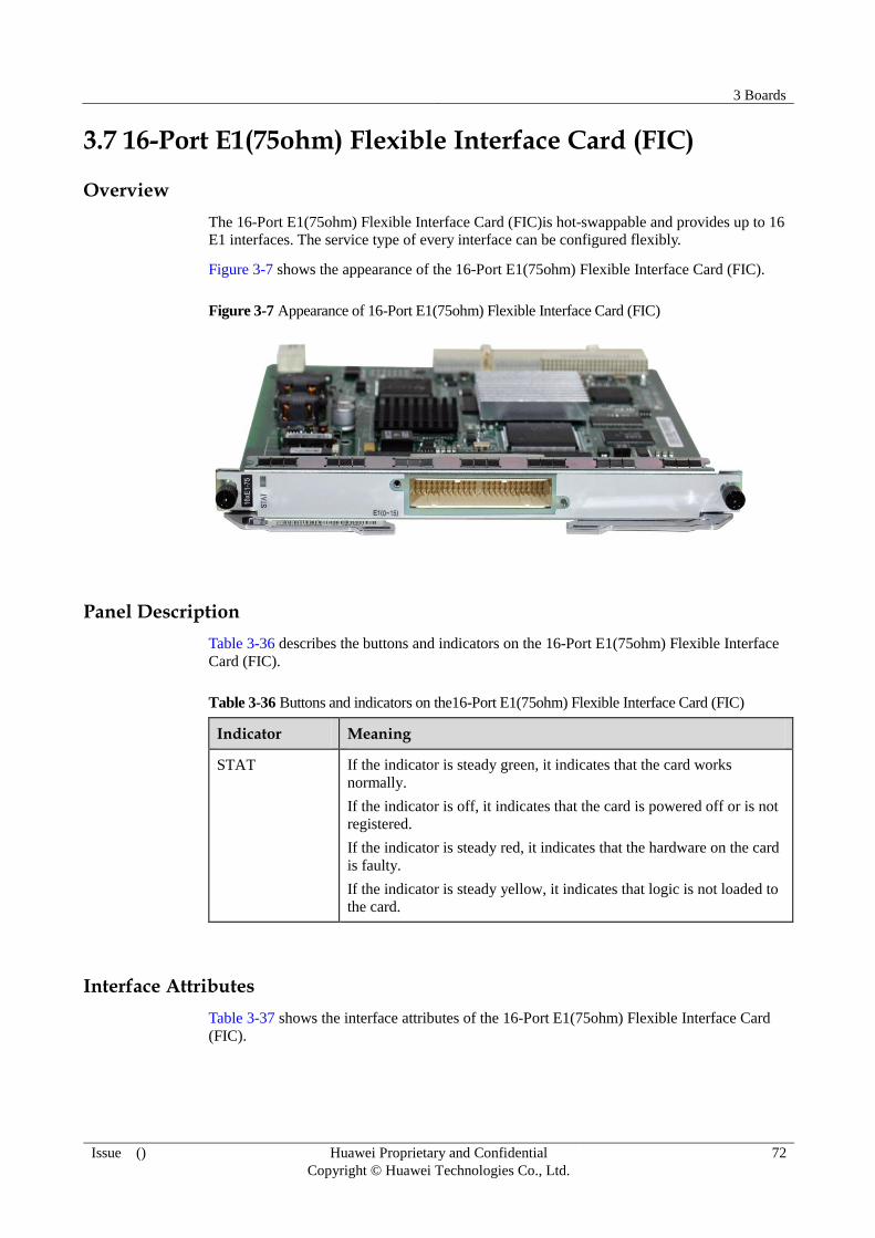
3 Boards
Issue () Huawei Proprietary and Confidential
Copyright © Huawei Technologies Co., Ltd.
72
3.7 16-Port E1(75ohm) Flexible Interface Card (FIC)
Overview
The 16-Port E1(75ohm) Flexible Interface Card (FIC)is hot-swappable and provides up to 16
E1 interfaces. The service type of every interface can be configured flexibly.
Figure 3-7 shows the appearance of the 16-Port E1(75ohm) Flexible Interface Card (FIC).
Figure 3-7 Appearance of 16-Port E1(75ohm) Flexible Interface Card (FIC)
Panel Description
Table 3-36 describes the buttons and indicators on the 16-Port E1(75ohm) Flexible Interface
Card (FIC).
Table 3-36 Buttons and indicators on the16-Port E1(75ohm) Flexible Interface Card (FIC)
Indicator Meaning
STAT If the indicator is steady green, it indicates that the card works
normally.
If the indicator is off, it indicates that the card is powered off or is not
registered.
If the indicator is steady red, it indicates that the hardware on the card
is faulty.
If the indicator is steady yellow, it indicates that logic is not loaded to
the card.
Interface Attributes
Table 3-37 shows the interface attributes of the 16-Port E1(75ohm) Flexible Interface Card
(FIC).

3 Boards
Issue () Huawei Proprietary and Confidential
Copyright © Huawei Technologies Co., Ltd.
73
Table 3-37 Interface attributes of the 16-Port E1(75ohm) Flexible Interface Card (FIC)
Attribute Description
Connector type Anea 96, 75 ohm
Nominal bit rate 2048 kbit/s
Interface
impedance
75 ohm
Interface code HDB3
Pulse waveform
of the output
interface
Compliant with ITU-T G0.703
Attenuation (dB)
of the input
interface at 1024
kHz
0 to 6
Immunity of the
input interface
Compliant with ITU-T G0.703
Input jitter
tolerance
Compliant with ITU-T G.823
Output jitter Compliant with ITU-T G.823
Technical Parameters
Table 3-38 shows the technical parameters of the16-Port E1(75ohm) Flexible Interface Card
(FIC) .
Table 3-38 Technical parameters of the 16-Port E1(75ohm) Flexible Interface Card (FIC)
Description Description
Silkscreen
16xE1-75
Typical power
consumption
15 W
Heat
dissipation
49 BTU/hour
Weight 0.45 kg ( 0.99 lb )
Dimensions
(W x D x H)
194 mm x 226 mm x 20 mm ( 7.64 in. x 8.90 in. x 0.79 in. )
Connector
type
Anea 96, 75 ohm
Earliest V600R002C03

3 Boards
Issue () Huawei Proprietary and Confidential
Copyright © Huawei Technologies Co., Ltd.
74
Description Description
software
version
Product Specifications
Table 3-39 lists the specifications of the 16-Port E1(75ohm) Flexible Interface Card (FIC).
Table 3-39 Specifications of the 16-Port E1(75ohm) Flexible Interface Card (FIC)
Feature Description
Protocol and services ATM/IMA: supporting up to eight IMA groups; 16 E1
links per IMA group
CES: supporting Circuit Emulation Service (CES) of up to
16 E1 links
ML-PPP: supports up to 7 ML-PPP groups.
Interface type Anea 96, 75 ohm
Reliability and availability Hardware feature
Hot-swappable
NMS Supporting command line management interfaces
Supporting SNMP and MIBs
Operating ambients Long-term operating temperature: -5°C to 50°C ( 23°F to
122°F )
Short-term operating temperature: -20°C to +60°C ( -4°F to
140°F )
Long-term relative humidity: 5% to 85%
Short-term relative humidity: 5% to 95%
Storage ambients Storage temperature: -40°C to +70°C ( -40°F to 158°F )
Storage humidity: 0% to 95%
3.8 16-Port E1(120ohm) Flexible Interface Card (FIC)
Overview
The 16-Port E1(120ohm) Flexible Interface Card (FIC)is hot-swappable and provides up to 16
E1 interfaces. The service type of every interface can be configured flexibly.
Figure 3-8 shows the appearance of the 16-Port E1(120ohm) Flexible Interface Card (FIC).

3 Boards
Issue () Huawei Proprietary and Confidential
Copyright © Huawei Technologies Co., Ltd.
75
Figure 3-8 Appearance of 16-Port E1(120ohm) Flexible Interface Card (FIC)
Panel Description
Table 3-40 describes the buttons and indicators on the 16-Port E1(120ohm) Flexible Interface
Card (FIC).
Table 3-40 Buttons and indicators on the 16-Port E1(120ohm) Flexible Interface Card (FIC)
Indicator Meaning
STAT If the indicator is steady green, it indicates that the card works
normally.
If the indicator is off, it indicates that the card is not powered on or
fails to be registered.
If the indicator is steady red, it indicates that the hardware of the card
is faulty.
If the indicator is steady yellow, it indicates that logic is not loaded to
the card.
Interface Attributes
Table 3-41 shows the interface attributes of the 16-Port E1(120ohm) Flexible Interface Card
(FIC).
Table 3-41 Interface attributes of the 16-Port E1(120ohm) Flexible Interface Card (FIC)
Attribute Description
Connector type Anea 96, 120 ohm
Nominal bit rate 2048 kbit/s
Interface
impedance
120 ohm
Interface code HDB3
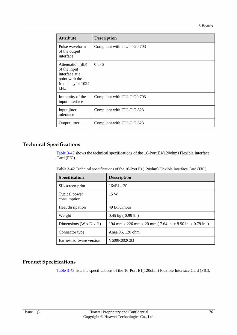
3 Boards
Issue () Huawei Proprietary and Confidential
Copyright © Huawei Technologies Co., Ltd.
76
Attribute Description
Pulse waveform
of the output
interface
Compliant with ITU-T G0.703
Attenuation (dB)
of the input
interface at a
point with the
frequency of 1024
kHz
0 to 6
Immunity of the
input interface
Compliant with ITU-T G0.703
Input jitter
tolerance
Compliant with ITU-T G.823
Output jitter Compliant with ITU-T G.823
Technical Specifications
Table 3-42 shows the technical specifications of the 16-Port E1(120ohm) Flexible Interface
Card (FIC).
Table 3-42 Technical specifications of the 16-Port E1(120ohm) Flexible Interface Card (FIC)
Specification Description
Silkscreen print 16xE1-120
Typical power
consumption
15 W
Heat dissipation 49 BTU/hour
Weight 0.45 kg ( 0.99 lb )
Dimensions (W x D x H) 194 mm x 226 mm x 20 mm ( 7.64 in. x 8.90 in. x 0.79 in. )
Connector type Anea 96, 120 ohm
Earliest software version V600R002C03
Product Specifications
Table 3-43 lists the specifications of the 16-Port E1(120ohm) Flexible Interface Card (FIC).

3 Boards
Issue () Huawei Proprietary and Confidential
Copyright © Huawei Technologies Co., Ltd.
77
Table 3-43 Specifications of the 16-Port E1(120ohm) Flexible Interface Card (FIC)
Feature Description
Protocol and services ATM/IMA: supporting up to eight IMA groups; 16 E1
links per IMA group
CES: supporting CES of up to 16 E1 links
ML-PPP: supporting up to 7 ML-PPP groups
Interface type Anea 96, 120 ohm
Reliability and availability Hardware feature
Hot-swappable
NMS Supporting command line management interfaces
Supporting SNMP and MIBs
Ambient operating
conditions
Long-term operating temperature: -5°C to 50°C ( 23°F to
122°F )
Short-term operating temperature: -20°C to +60°C ( -4°F to
140°F )
Long-term relative humidity: 5% to 85%
Short-term relative humidity: 5% to 95%
Ambient storage
conditions Storage temperature: -40°C to +70°C ( -40°F to 158°F )
Storage humidity: 0% to 95%
3.9 Auxiliary Flexible Interface Card with 4-Port 100Base-RJ45(FIC, Supporting 1588v2)
Overview
The Auxiliary Flexible Interface Card with 4-Port 100Base-RJ45(FIC, Supporting 1588v2)
mainly inputs 4-channel FE electrical signals. The Boolean value input and output interfaces
on the card can be connected to the burglarproof sensor (on the cabinet door) and smoke
sensor to implement on-site ambient monitoring.
The alarm input interface (ALMI) on the AUXQ is used to input four channels (numbered
from 1 to 4) of alarm signals. The ALMI interface can be connected to sensors such as the
burglarproof sensor and the smoke sensor on the cabinet door, or to other environment
monitoring devices. The environment monitoring device collects the environment monitoring
information and outputs the information to the device through the ALMI interface. If any
exception occurs in the working environment of the device, the device generates an alarm
accordingly and reports the alarm to the NMS for real-time monitoring and management.
Users can run a command to configure which channel (1 to 4 channels) and which object
(temperature, voltage, current, smoke, and cabinet door) to be monitored. The device then
determines whether to report the associated alarm to the NMS based on the configuration
performed by users.

3 Boards
Issue () Huawei Proprietary and Confidential
Copyright © Huawei Technologies Co., Ltd.
78
On one device, only oneAuxiliary Flexible Interface Card with 4-Port 100Base-RJ45(FIC, Supporting
1588v2) can be housed.
The Auxiliary Flexible Interface Card with 4-Port 100Base-RJ45(FIC, Supporting
1588v2)consists of the service access module, auxiliary interface module, control drive
module, clock module, and power module.
Service access module
− Inputs 4-channel FE electrical signals.
− Implements physical-layer interface functions and supports Medium Access Control
(MAC) address-based communications.
− Supports the signal cache function to prevent FE signal loss.
− Supports the flow control function to control the packet volume.
− Processes IEEE 1588v2 packets.
Auxiliary interface module
− Provides 4-channel alarm input interfaces.
Control drive module
− Detects the system status through the management and control bus.
− Processes alarm signals, orderwire signals, and transparent data signals.
− Supports hot swapping.
Clock module
− Provides clock signals for service access and convergence module.
− Provides clock signals for the auxiliary interface module.
− Supports synchronous Ethernet and the Synchronization Status Message (SSM)
protocol.
− Supports IEEE 1588v2.
Power module
− Inputs 2-channel -48 V/-60 V DC power.
− Supplies 3.3 V or 1.2 V power.
Table 3-44 Description of the interfaces on the Auxiliary Flexible Interface Card with 4-Port
100Base-RJ45(FIC, Supporting 1588v2)
Interface Type Description
F1 RJ-45 Reserved
PHONE RJ-45 Reserved
ALMO RJ-45 Reserved
ALMI RJ-45 Interface that inputs four
channels of alarm signals
FE0-FE3 RJ-45 Interfaces that input and
output FE electrical signals

3 Boards
Issue () Huawei Proprietary and Confidential
Copyright © Huawei Technologies Co., Ltd.
79
Interface Type Description
NOTE
The FE0 to FE3 interfaces, and F1 interface support auto-adaptation to a straight-through network cable
or a crossover network cable.
Figure 3-9 shows the appearance of the Auxiliary Flexible Interface Card with 4-Port
100Base-RJ45(FIC, Supporting 1588v2).
Figure 3-9 Appearance of the Auxiliary Flexible Interface Card with 4-Port 100Base-RJ45(FIC,
Supporting 1588v2)
Panel Description
Table 3-45 describes the indicators on the Auxiliary Flexible Interface Card with 4-Port
100Base-RJ45(FIC, Supporting 1588v2).
Table 3-45 Description of the indicators on the Auxiliary Flexible Interface Card with 4-Port
100Base-RJ45(FIC, Supporting 1588v2)
Indicator Description
STAT If the indicator is steady green, it indicates that the card works
normally.
If the indicator is off, it indicates that the card is not powered on or
fails to be registered.
If the indicator is steady red, it indicates that the hardware on the card
is faulty.
If the indicator is steady yellow, it indicates that logic is not loaded to
the card.
Interface Attributes
Table 3-46 lists the interface attributes of the Auxiliary Flexible Interface Card with 4-Port
100Base-RJ45(FIC, Supporting 1588v2).

3 Boards
Issue () Huawei Proprietary and Confidential
Copyright © Huawei Technologies Co., Ltd.
80
Table 3-46 Interface attributes of the Auxiliary Flexible Interface Card with 4-Port
100Base-RJ45(FIC, Supporting 1588v2)
Attribute Description
Connector RJ45
Working mode Full-duplex
Standard
compliance
IEEE 802.3-2002
Frame format Ethernet_II, Ethernet_SAP, and Ethernet_SNAP
Network protocol IP
Table 3-47 describes the pins of the ALMI interface.
Table 3-47 Pins of the ALMI interface
Front View Pin Usage
18 24 3567
1 Alarm input signal 1
2 Ground for alarm input signal 1
3 Alarm input signal 2
4 Alarm input signal 3
5 Ground for alarm input signal 3
6 Ground for alarm input signal 2
7 Alarm input signal 4
8 Ground for alarm input signal 4
Technical Specifications
Table 3-48 lists the technical specifications of the Auxiliary Flexible Interface Card with
4-Port 100Base-RJ45(FIC, Supporting 1588v2).
Table 3-48 Technical specifications of the Auxiliary Flexible Interface Card with 4-Port
100Base-RJ45(FIC, Supporting 1588v2)
Item Description
Silkscreen
AUX/4xFE-A
Typical power
consumption 10 W
Heat 32 BTU/hour
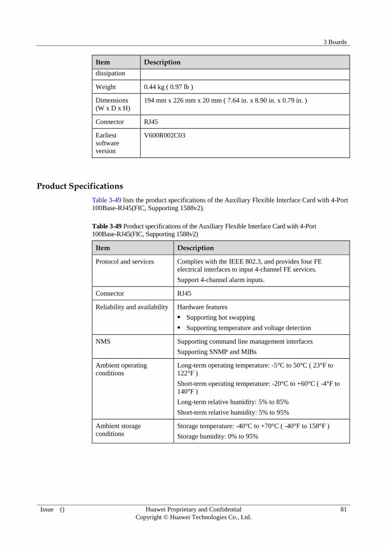
3 Boards
Issue () Huawei Proprietary and Confidential
Copyright © Huawei Technologies Co., Ltd.
81
Item Description
dissipation
Weight 0.44 kg ( 0.97 lb )
Dimensions
(W x D x H)
194 mm x 226 mm x 20 mm ( 7.64 in. x 8.90 in. x 0.79 in. )
Connector RJ45
Earliest
software
version
V600R002C03
Product Specifications
Table 3-49 lists the product specifications of the Auxiliary Flexible Interface Card with 4-Port
100Base-RJ45(FIC, Supporting 1588v2).
Table 3-49 Product specifications of the Auxiliary Flexible Interface Card with 4-Port
100Base-RJ45(FIC, Supporting 1588v2)
Item Description
Protocol and services Complies with the IEEE 802.3, and provides four FE
electrical interfaces to input 4-channel FE services.
Support 4-channel alarm inputs.
Connector RJ45
Reliability and availability Hardware features
Supporting hot swapping
Supporting temperature and voltage detection
NMS Supporting command line management interfaces
Supporting SNMP and MIBs
Ambient operating
conditions
Long-term operating temperature: -5°C to 50°C ( 23°F to
122°F )
Short-term operating temperature: -20°C to +60°C ( -4°F to
140°F )
Long-term relative humidity: 5% to 85%
Short-term relative humidity: 5% to 95%
Ambient storage
conditions
Storage temperature: -40°C to +70°C ( -40°F to 158°F )
Storage humidity: 0% to 95%

3 Boards
Issue () Huawei Proprietary and Confidential
Copyright © Huawei Technologies Co., Ltd.
82
3.10 1-Port Channelized OC3c/STM1c POS-SFP Flexible Interface Card (FIC)
Overview
The 1-port channelized STM-1 flexible card transmits 63-channel E1 signals through
1-channel 155M SDH line, implements the Circuit Emulation Service (CES), Inverse
Multiplexing for ATM (IMA), and MultiLink Point-to-Point Protocol (ML-PPP), and supports
synchronous Ethernet and hot swapping. The second channelized STM-1 interface on the
right of front panel is reserved and cannot be used to carry services.
The 1-Port Channelized OC3c/STM1c POS-SFP Flexible Interface Card (FIC)consists of the
service access module, auxiliary interface module, control drive module, clock module, and
power module.
Figure 3-10 shows the appearance of the 1-Port Channelized OC3c/STM1c POS-SFP Flexible
Interface Card (FIC).
Figure 3-10 Appearance of the 1-Port Channelized OC3c/STM1c POS-SFP Flexible Interface
Card (FIC)
Panel Description
Table 3-50 describes the indicators on the1-Port Channelized OC3c/STM1c POS-SFP
Flexible Interface Card (FIC) .
Table 3-50 Description of the indicators on the 1-Port Channelized OC3c/STM1c POS-SFP
Flexible Interface Card (FIC)
Indicator Description
STAT If the indicator is steady green, it indicates that the1-Port Channelized
OC3c/STM1c POS-SFP Flexible Interface Card (FIC) works
normally.
If the indicator is off, it indicates that the 1-Port Channelized
OC3c/STM1c POS-SFP Flexible Interface Card (FIC) is not powered
on or fails to be registered.
If the indicator is steady red, it indicates that the hardware of the

3 Boards
Issue () Huawei Proprietary and Confidential
Copyright © Huawei Technologies Co., Ltd.
83
Indicator Description
1-Port Channelized OC3c/STM1c POS-SFP Flexible Interface Card
(FIC)is faulty.
If the indicator is steady yellow, it indicates that logic is not loaded to
the 1-Port Channelized OC3c/STM1c POS-SFP Flexible Interface
Card (FIC).
LOS1/LOS2 If the indicator is steady green, it indicates that optical signals are
normal.
If the indicator is steady red, it indicates that optical signals are lost.
If the indicator is off, it indicates that the optical module is not
installed.
Interface Attributes
Table 3-51 lists the interface attributes of the 1-Port Channelized OC3c/STM1c POS-SFP
Flexible Interface Card (FIC).
Table 3-51 Interface attributes of the 1-Port Channelized OC3c/STM1c POS-SFP Flexible
Interface Card (FIC)
Attribute Description
Connector type LC/PC
Optical interface
attribute
Determined by the selected SFP optical module (for attributes of the
SFP optical module, see Table 3-52)
Working mode Full duplex
Link protocol ML-PPP
Network
protocols
IP
Table 3-52 Attributes of the 155-Mbit/s SFP optical module
Attribute Description
Transmission
distance
2 km ( 1.24
mi. )
15 km ( 9.32
mi. )
40 km ( 24.86
mi. )
80 km ( 49.71
mi. )
Center
wavelength
1310 nm 1310 nm 1310 nm 1550 nm
Minimum
transmit
optical power
-19.0 dBm -15.0 dBm -5.0 dBm -5.0 dBm
Maximum
transmit
-14.0 dBm -8.0 dBm 0 dBm 0 dBm

3 Boards
Issue () Huawei Proprietary and Confidential
Copyright © Huawei Technologies Co., Ltd.
84
Attribute Description
optical power
Receiver
sensitivity
-30.0 dBm -31.0 dBm -37.0 dBm -37.0 dBm
Overload
optical power
-14.0 dBm -8.0 dBm -10.0 dBm -10.0 dBm
Fiber mode Multi-mode Single-mode Single-mode Single-mode
Technical Specifications
Table 3-53 lists the technical specifications of the 1-Port Channelized OC3c/STM1c POS-SFP
Flexible Interface Card (FIC).
Table 3-53 Technical specifications of the 1-Port Channelized OC3c/STM1c POS-SFP Flexible
Interface Card (FIC)
Item Description
Silkscreen
1xOC3/cPOS
Typical power
consumption
17 W
Heat
dissipation
55 BTU/hour
Weight 0.55 kg ( 1.21 lb )
Dimensions
(W x D x H)
194 mm x 226 mm x 20 mm ( 7.64 in. x 8.90 in. x 0.79 in. )
Connector
type
SFP
Earliest
software
version
V600R002C03
Product Specifications
Table 3-54 shows the product specifications of the 1-Port Channelized OC3c/STM1c
POS-SFP Flexible Interface Card (FIC).

3 Boards
Issue () Huawei Proprietary and Confidential
Copyright © Huawei Technologies Co., Ltd.
85
Table 3-54 Product specifications of the 1-Port Channelized OC3c/STM1c POS-SFP Flexible
Interface Card (FIC)
Item Description
Protocol and services Supporting 63 channels and 7 MP groups
Supporting 32 IMA groups and 63 VC-12 timeslots or serial
ports in each IMA group
Connector type SFP
Reliability and availability Hardware feature
Supporting hot swapping
NMS Supporting command line management interfaces
Supporting SNMP and MIBs
Ambient operating
conditions
Long-term operating temperature: -5°C to 50°C ( 23°F to
122°F )
Short-term operating temperature: -20°C to +60°C (-4°F to
140°F )
Long-term relative humidity: 5% to 85%
Short-term relative humidity: 5% to 95%
Ambient storage
conditions
Storage temperature: -40°C to +70°C ( -40°F to 158°F )
Storage humidity: 0% to 95%
3.11 4-Port OC-3c/STM-1c ATM SFP Flexible Interface Card (FIC)
Overview
The 4-Port OC-3c/STM-1c ATM SFP FIC supports cell packing and can be equipped with
various types of optical modules.Figure 3-11 shows the appearance of the 4-Port
OC-3c/STM-1c ATM SFP FIC.
Figure 3-11 4-Port OC-3c/STM-1c ATM SFP FIC

3 Boards
Issue () Huawei Proprietary and Confidential
Copyright © Huawei Technologies Co., Ltd.
86
Panel Description
Table 3-55 describes the indicators on the 4-Port OC-3c/STM-1c ATM SFP FIC.
Table 3-55 Indicators on the 4-Port OC-3c/STM-1c ATM SFP FIC
Indicator Description
STAT If the indicator is steady green, the 4-Port OC-3c/STM-1c ATM SFP
FIC is working properly.
If the indicator is steady off, the 4-Port OC-3c/STM-1c ATM SFP FIC
does not register or is powered off.
If the indicator is steady red, the 4-Port OC-3c/STM-1c ATM SFP
FIC has hardware faults.
If the indicator is steady yellow, no logic is loaded to the 4-Port
OC-3c/STM-1c ATM SFP FIC.
LINK/ACT
(green)
If the indicator is steady on, the link is working properly.
If the indicator blinks, data is being transmitted.
If the indicator is steady off, the link is not working properly.
Interface attributes
Table 3-56 lists the interface attributes of the 4-Port OC-3c/STM-1c ATM SFP FIC.
Table 3-56 Interface attributes of the 4-Port OC-3c/STM-1c ATM SFP FIC
Attribute Description
Connector type LC/PC
Interface attribute Determined by the selected SFP optical module
Working mode Full-duplex
Link protocol IPoA
Supported
network protocol
IP
Table 3-57 Attributes of the 155 M SFP optical module
Attribute Description
Maximum
transmission
distance
2 km ( 1.24 mi. ) 15 km ( 9.32
mi. )
40 km ( 24.86
mi. )
80 km ( 49.71
mi. )
Center
wavelength
1310 nm 1310 nm 1310 nm 1550 nm

3 Boards
Issue () Huawei Proprietary and Confidential
Copyright © Huawei Technologies Co., Ltd.
87
Attribute Description
Minimum
transmit optical
power
-19.0 dBm -15.0 dBm -5.0 dBm -5.0 dBm
Maximum
transmit optical
power
-14.0 dBm -8.0 dBm 0 dBm 0 dBm
Receiver
sensitivity
-30.0 dBm -31.0 dBm -37.0 dBm -37.0 dBm
Overload
optical power
-14.0 dBm -8.0 dBm -10.0 dBm -10.0 dBm
Fiber mode Multi-mode Single-mode Single-mode Single-mode
Technical Specifications
Table 3-58 lists the technical specifications of the 4-Port OC-3c/STM-1c ATM SFP FIC.
Table 3-58 Technical specifications of the 4-Port OC-3c/STM-1c ATM SFP FIC
Item Description
Silkscreen 4×OC3c-ATM
Typical power
consumption
23 W
Heat
dissipation
75B TU/hour
Board weight 0.89 kg ( 1.96 lb )
Dimensions
(width x depth
x height)
194 mm x 226 mm x 20 mm ( 7.64 in. x 8.90 in. x 0.79 in. )
Connector
type
LC/PC
Earliest
software
version
V600R003C00SPC800
Product Specifications
Table 3-59 lists the product specifications of the 4-Port OC-3c/STM-1c ATM SFP FIC.

3 Boards
Issue () Huawei Proprietary and Confidential
Copyright © Huawei Technologies Co., Ltd.
88
Table 3-59 Product specifications of the 4-Port OC-3c/STM-1c ATM SFP FIC
Item Description
Protocol and services CBR, rtVBR, nrtVBR, and UBR
PVC shaping and PVP shaping
IWF
ATM cell relay
ATM cell concatenation
Connector type SFP LC
Reliability and availability Hardware feature: supporting hot swap
NMS Enhanced command-line interface
SNMP and MIB supported
Ambient operating
conditions
Long-term working temperature: -5°C to +50°C ( 23°F to
122°F )
Short-term working temperature: -20°C to +60°C ( -4°F to
140°F )
Long-term relative humidity: 5% to 85%
Short-term relative humidity: 5% to 95%
Storage environment Storage temperature: -40°C to +70°C ( -40°F to 158°F )
Storage humidity: 0% to 95%

4 Cables
Issue () Huawei Proprietary and Confidential
Copyright © Huawei Technologies Co., Ltd.
89
4 Cables
About This Chapter
This chapter describes the structure and specifications of the external cables.
4.1 Power Cable
This section describes the structure and technical specifications of the power cable.
4.2 Chassis and Cabinet Grounding Cable
This section describes the structure and technical specifications of the chassis and cabinet
ground cable.
4.3 Console Port Cable
This section describes the structure and technical specifications of the console interface cable.
4.4 Auxiliary Port Cable
This section describes the structure and technical specifications of the AUX interface cable.
4.5 Clock Cable
This section describes the structure and technical specifications of the clock cable.
4.6 Ethernet Cable
Ethernet cables are classigied into two types: straight-through cables and crossover cables.
4.7 Optical Fiber
This section describes the structure and technical specifications of the optical fiber.
4.8 16xE1 Cable
This section describes the structure and technical specifications of the 16xE1 cable.
4.9 Alarm Input/Output Cables
This section describes the structure and technical specifications of the Alarm Input/Output
Cables.
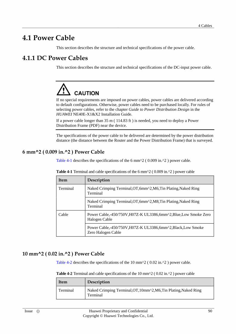
4 Cables
Issue () Huawei Proprietary and Confidential
Copyright © Huawei Technologies Co., Ltd.
90
4.1 Power Cable
This section describes the structure and technical specifications of the power cable.
4.1.1 DC Power Cables
This section describes the structure and technical specifications of the DC-input power cable.
If no special requirements are imposed on power cables, power cables are delivered according
to default configurations. Otherwise, power cables need to be purchased locally. For rules of
selecting power cables, refer to the chapter Guide to Power Distribution Design in the
HUAWEI NE40E-X1&X2 Installation Guide.
If a power cable longer than 35 m ( 114.83 ft ) is needed, you need to deploy a Power
Distribution Frame (PDF) near the device.
The specifications of the power cable to be delivered are determined by the power distribution
distance (the distance between the Router and the Power Distribution Frame) that is surveyed.
6 mm^2 ( 0.009 in.^2 ) Power Cable
Table 4-1 describes the specifications of the 6 mm^2 ( 0.009 in.^2 ) power cable.
Table 4-1 Terminal and cable specifications of the 6 mm^2 ( 0.009 in.^2 ) power cable
Item Description
Terminal Naked Crimping Terminal,OT,6mm^2,M6,Tin Plating,Naked Ring
Terminal
Naked Crimping Terminal,OT,6mm^2,M8,Tin Plating,Naked Ring
Terminal
Cable Power Cable,-450/750V,H07Z-K UL3386,6mm^2,Blue,Low Smoke Zero
Halogen Cable
Power Cable,-450/750V,H07Z-K UL3386,6mm^2,Black,Low Smoke
Zero Halogen Cable
10 mm^2 ( 0.02 in.^2 ) Power Cable
Table 4-2 describes the specifications of the 10 mm^2 ( 0.02 in.^2 ) power cable.
Table 4-2 Terminal and cable specifications of the 10 mm^2 ( 0.02 in.^2 ) power cable
Item Description
Terminal Naked Crimping Terminal,OT,10mm^2,M6,Tin Plating,Naked Ring
Terminal

4 Cables
Issue () Huawei Proprietary and Confidential
Copyright © Huawei Technologies Co., Ltd.
91
Item Description
Naked Crimping Terminal,OT,10mm^2,M8,Tin Plating,Naked Ring
Terminal
Cable Power Cable,-450/750V,H07Z-K UL3386,10mm^2,Blue,Low Smoke
Zero Halogen Cable
Power Cable,-450/750V,H07Z-K UL3386,10mm^2,Black,Low Smoke
Zero Halogen Cable
4.1.2 AC Power Cables
This section describes the structure and technical specifications of the AC-input power cable.
If no special requirements are imposed on power cables, power cables are delivered according
to default configurations. Otherwise, power cables need to be purchased locally. For rules of
selecting power cables, refer to the corresponding computation formula in Guide to Power
Distribution Design.
Table 4-3 describes the specifications of the AC Power Cables.
Table 4-3 AC Power Cables
Item Description
Cable Type External Suite, Power Cords All Over The World, Class I
Equipment With Connector C13, External Cable Set
4.2 Chassis and Cabinet Grounding Cable
This section describes the structure and technical specifications of the chassis and cabinet
ground cable.
4.2.1 Introduction
The chassis and cabinet ground cables are used to ground a chassis and a cabinet. Before the
delivery of a device, ground cables are correctly connected to the front, back and side doors of
the cabinet.
4.2.2 Structure
The connector of the chassi and cabinet ground cable is the same as the connector of the
DC-input power cable.

4 Cables
Issue () Huawei Proprietary and Confidential
Copyright © Huawei Technologies Co., Ltd.
92
4.2.3 Technical Specifications
Table 4-4 lists the technical specifications of the NE40E-X1 and cabinet ground cable..
Table 4-4 Technical specifications of the NE40E-X1 and cabinet ground cable
Item Description
PGND cable Terminal Naked Crimping Terminal,OT,6mm^2,M4,Tin
Plating,Naked Ring Terminal
Cable type Power Cable,-450/750V,H07Z-K
UL3386,6mm^2,olivine
Fireproof class CM
Table 4-5 lists the technical specifications of the NE40E-X2 and cabinet ground cable..
Table 4-5 Technical specifications of the NE40E-X2 and cabinet ground cable
Item Description
PGND cable Terminal Naked Crimping Terminal,OT,10mm^2,M6,Tin
Plating,Naked Ring Terminal
Cable type Power Cable,-450/750V,H07Z-K
UL3386,10mm^2,olivine
Fireproof class CM
4.3 Console Port Cable
This section describes the structure and technical specifications of the console interface cable.
4.3.1 Introduction
The console interface cable is used to connect the console interface on the NE40E to the serial
interface of the console to transmit configuration data of the NE40E.
The console interface cable is an 8-core shielded cable. One end of the cable is an RJ45
connector connected to the console interface on the MPU. The other end has DB9 and DB25
connectors, either of which is connected to the serial interface on a computer.
4.3.2 Structure
Figure 4-1 shows the structure of a console interface cable. Table 4-6 shows the pin
assignment on the console interface cable.

4 Cables
Issue () Huawei Proprietary and Confidential
Copyright © Huawei Technologies Co., Ltd.
93
Figure 4-1 Console interface cable
1. Direction
A
2. DB25 female
connector
3. Label 4. RJ45 connector
5. Direction
B
6. Direction C 7. DB9 female
connector
W1 and W2 communication
cable
Table 4-6 Pin assignment on the console interface cable
RJ45 Direction DB25 DB9 Signal
1 -> 5 8 CTS (Clear to Send)
2 -> 6 6 DSR (Data Set Ready)
3 -> 3 2 RXD (Receive Data)
4 - 7 5 GND
5 - 8 1 GND
6 <- 2 3 TXD (Transmit Data)
7 <- 20 4 DTR (Data Terminal Ready)
8 <- 4 7 RTS (Request to Send)
4.3.3 Technical Specifications
Table 4-7 lists the technical specifications of the console interface cable.
Table 4-7 Technical specifications of the console interface cable
Item Description
Connector X1 Network interface connector-crystal connector -8PIN-8bit-shielded plug
Connector X2 Cable connector-D style-25PIN-female

4 Cables
Issue () Huawei Proprietary and Confidential
Copyright © Huawei Technologies Co., Ltd.
94
Item Description
Connector X3 Cable connector-D style-9PIN-female
Cable type Symmetrical twisted
cable-120-ohm-SEYVPV-0.5mm-24AWG-8core-PANTONE 430U
Symmetrical twisted
cable-100-ohm-SEYVP-0.48mm-26AWG-8core-black
Number of
cores
8
Fireproof class CM
Available
length
15 m ( 49.21 ft ) for the 120-ohm cable
3 m ( 9.84 ft ) for the 100-ohm cable
4.4 Auxiliary Port Cable
This section describes the structure and technical specifications of the AUX interface cable.
4.4.1 Introduction
The AUX interface cable is used to connect the AUX interface on the NE40E to a modem to
remotely transmit the configuration data of the NE40E.
The AUX interface cable is an 8-core shielded cable. One end of the cable is an RJ45
connector connected to the AUX interface on the MPU. The other end has DB9 and DB25
connectors, either of which is connected to the serial interface on a computer.
4.4.2 Structure
As shown in Figure 4-2 the structure of the AUX interface cable is the same as that of the
console interface cable. Table 4-8 shows the pin assignment on the AUX interface cable.

4 Cables
Issue () Huawei Proprietary and Confidential
Copyright © Huawei Technologies Co., Ltd.
95
Figure 4-2 AUX interface cable
1. Direction
A
2. DB25 female
connector
3. Label 4. RJ45 connector
5. Direction
B
6. Direction C 7. DB9 female
connector
W1 and W2 communication
cable
Table 4-8 Pin assignment on the AUX interface cable
RJ-45 Direction DB-25 DB-9 Signal
1 -> 4 7 RTS
2 -> 20 4 DTR
3 -> 2 3 TXD
4 - 8 1 GND
5 - 7 5 GND
6 <- 3 2 RXD
7 <- 6 6 DSR
8 <- 5 8 CTS
4.4.3 Technical Specifications
Table 4-9 lists the technical specifications of the AUX interface cable.
Table 4-9 Technical specifications of the AUX interface cable
Item Description
Connector X1 Network interface connector-crystal connector-8PIN-8bit-shielded plug
Connector X2 Cable connector-D type-25PIN-female
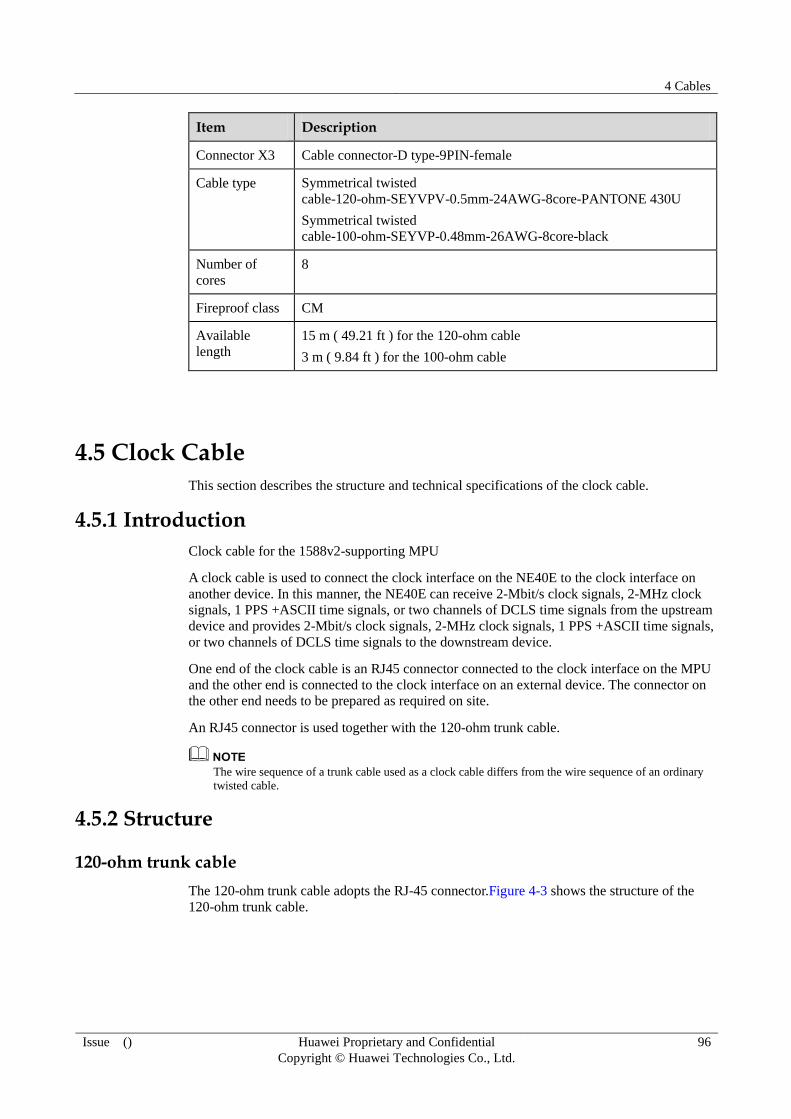
4 Cables
Issue () Huawei Proprietary and Confidential
Copyright © Huawei Technologies Co., Ltd.
96
Item Description
Connector X3 Cable connector-D type-9PIN-female
Cable type Symmetrical twisted
cable-120-ohm-SEYVPV-0.5mm-24AWG-8core-PANTONE 430U
Symmetrical twisted
cable-100-ohm-SEYVP-0.48mm-26AWG-8core-black
Number of
cores
8
Fireproof class CM
Available
length
15 m ( 49.21 ft ) for the 120-ohm cable
3 m ( 9.84 ft ) for the 100-ohm cable
4.5 Clock Cable
This section describes the structure and technical specifications of the clock cable.
4.5.1 Introduction
Clock cable for the 1588v2-supporting MPU
A clock cable is used to connect the clock interface on the NE40E to the clock interface on
another device. In this manner, the NE40E can receive 2-Mbit/s clock signals, 2-MHz clock
signals, 1 PPS +ASCII time signals, or two channels of DCLS time signals from the upstream
device and provides 2-Mbit/s clock signals, 2-MHz clock signals, 1 PPS +ASCII time signals,
or two channels of DCLS time signals to the downstream device.
One end of the clock cable is an RJ45 connector connected to the clock interface on the MPU
and the other end is connected to the clock interface on an external device. The connector on
the other end needs to be prepared as required on site.
An RJ45 connector is used together with the 120-ohm trunk cable.
The wire sequence of a trunk cable used as a clock cable differs from the wire sequence of an ordinary
twisted cable.
4.5.2 Structure
120-ohm trunk cable
The 120-ohm trunk cable adopts the RJ-45 connector.Figure 4-3 shows the structure of the
120-ohm trunk cable.

4 Cables
Issue () Huawei Proprietary and Confidential
Copyright © Huawei Technologies Co., Ltd.
97
Figure 4-3 120-ohm trunk cable
Table 4-10 shows the pin assignments on the 120-ohm trunk cable.
Table 4-10 Pin assignments of the 120-ohm trunk cable
Connector X1 Connector X2 Relationship
X1.5 X2.2 Twisted
X1.4 X2.1
X1.2 X2.5 Twisted
X1.1 X2.4
X1.3 X2.7 Twisted
X1.6 X2.8
X1.7 X2.3 Twisted
X1.8 X2.6
4.5.3 Technical Specifications
Table 4-11 lists the technical specifications of the 120-ohm trunk cable.
Table 4-11 Technical specifications of the 120-ohm trunk cable
Item Description
120-ohm
cable
Connector Network interface connector-8 PIN-8 bit-shielded-crystal
model plug
Type Cable,120ohm,1E1,0.4mm,MP8-II,120CC4P0.4P430U(S),MP
8-II,Expert 2.0
Length 3 m ( 9.84 ft ), 15 m ( 49.21 ft ), 30 m (98.42 ft ), 60 m
( 196.85 ft )and 80 m ( 262.46 ft )
4.6 Ethernet Cable
Ethernet cables are classigied into two types: straight-through cables and crossover cables.

4 Cables
Issue () Huawei Proprietary and Confidential
Copyright © Huawei Technologies Co., Ltd.
98
4.6.1 Introduction
Ethernet cable is of two types: the straight-through cable and the crossover cable.
Straight-through Cable
The straight-through cable is used to connect the Ethernet interfaces between the following
devices:
A Router device and a hub
A Router device and an Ethernet switch
A computer and an Ethernet switch
A computer and a hub
Crossover Cable
The crossover cable is used to connect the Ethernet interfaces between the following devices:
A Router device and a Router device
A Router device and a computer
A hub and a hub
A hub and a switch
A switch and a switch
A computer and a computer
4.6.2 Structure
As shown in Figure 4-4, the straight-through cable and the crossover cable are standard
shielded network cables and, adopt an RJ45 connector shown in Figure 4-5.
Figure 4-4 Network cable
1. Connector - RJ45 2. Label 1 3. Main label 4. Label 2

4 Cables
Issue () Huawei Proprietary and Confidential
Copyright © Huawei Technologies Co., Ltd.
99
Figure 4-5 RJ45 connector
Table 4-12 and Table 4-13 show the pin assignments of the straight-through cable and the
crossover cable respectively.
Table 4-12 Pin assignments of the straight-through cable
Connector X1 Connector X2 Color Relationship
X1.2 X2.2 Orange Twisted
X1.1 X2.1 White/orange
X1.6 X2.6 Green Twisted
X1.3 X2.3 White/green
X1.4 X2.4 Blue Twisted
X1.5 X2.5 White/blue
X1.8 X2.8 Brown Twisted
X1.7 X2.7 White/brown
Table 4-13 Pin assignments of the crossover cable
Connector X1 Connector X2 Color Relationship
X1.6 X2.2 Orange Twisted
X1.3 X2.1 White/orange
X1.2 X2.6 Green Twisted
X1.1 X2.3 White/green
X1.4 X2.4 Blue Twisted
X1.5 X2.5 White/blue
X1.8 X2.8 Brown Twisted
X1.7 X2.7 White/brown
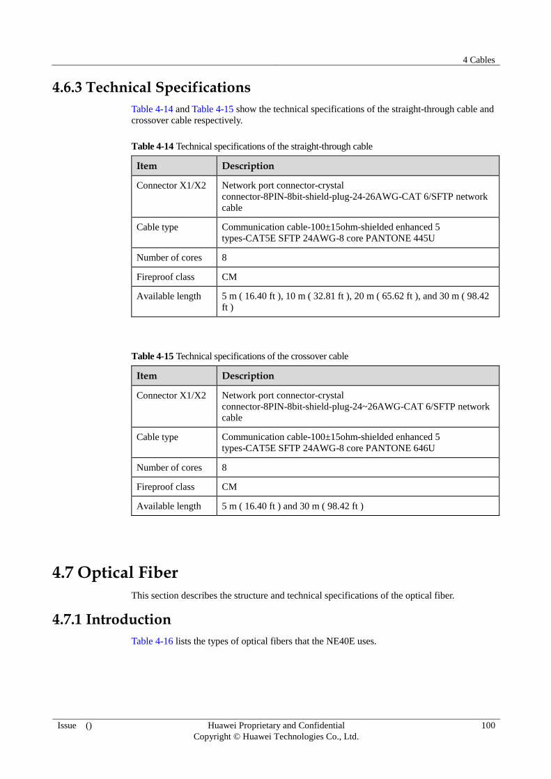
4 Cables
Issue () Huawei Proprietary and Confidential
Copyright © Huawei Technologies Co., Ltd.
100
4.6.3 Technical Specifications
Table 4-14 and Table 4-15 show the technical specifications of the straight-through cable and
crossover cable respectively.
Table 4-14 Technical specifications of the straight-through cable
Item Description
Connector X1/X2 Network port connector-crystal
connector-8PIN-8bit-shield-plug-24-26AWG-CAT 6/SFTP network
cable
Cable type Communication cable-100±15ohm-shielded enhanced 5
types-CAT5E SFTP 24AWG-8 core PANTONE 445U
Number of cores 8
Fireproof class CM
Available length 5 m ( 16.40 ft ), 10 m ( 32.81 ft ), 20 m ( 65.62 ft ), and 30 m ( 98.42
ft )
Table 4-15 Technical specifications of the crossover cable
Item Description
Connector X1/X2 Network port connector-crystal
connector-8PIN-8bit-shield-plug-24~26AWG-CAT 6/SFTP network
cable
Cable type Communication cable-100±15ohm-shielded enhanced 5
types-CAT5E SFTP 24AWG-8 core PANTONE 646U
Number of cores 8
Fireproof class CM
Available length 5 m ( 16.40 ft ) and 30 m ( 98.42 ft )
4.7 Optical Fiber
This section describes the structure and technical specifications of the optical fiber.
4.7.1 Introduction
Table 4-16 lists the types of optical fibers that the NE40E uses.

4 Cables
Issue () Huawei Proprietary and Confidential
Copyright © Huawei Technologies Co., Ltd.
101
Table 4-16 Types of optical fibers
No. Description Local Connector Remote Connector Cable Mode
1 Fiber connecting
an interface board
to the ODF
LC/PC FC/PC Single-mode
2 Fiber connecting
interface boards
LC/PC LC/PC or SC/PC Single-mode
/multi-mode
3 Fiber connecting
an interface board
to another device
LC/PC LC/PC or SC/PC Single-mode
/multi-mode
The optical transmission module of the multi-transverse mode needs to be connected to the
multi-mode fiber. The optical transmitting module of the single-longitudinal mode or
multi-longitudinal mode needs to be connected to the single-mode fiber.
4.7.2 Optical Connectors
The NE40E uses the LC/PC optical connector.
The outlines and operations of the connector and the precautions that you should take when
plugging and unplugging the connector are described in the following sections.
LC/PC Optical Connector
Figure 4-6 shows the outline of the LC/PC optical connector.
Figure 4-6 LC/PC optical connector
The plugging/unplugging of LC/PC optical interface only needs an axial operation instead of a rotation.

4 Cables
Issue () Huawei Proprietary and Confidential
Copyright © Huawei Technologies Co., Ltd.
102
The operation procedures and precautions are as follows:
Cautiously align the head of the fiber jumper with the optical interface on the optical
board and push in the fiber with proper strength.
Press the clip before pulling it out. Push in the fiber connector inward slightly, and then
pull out the connector.
4.7.3 Technical Specifications
Table 4-17 shows the technical specifications of the optical fiber.
Table 4-17 Technical specifications of the optical fiber
Item Description
Fiber transmission mode Single-mode/Multi-mode
Fiber connector 1 LC/PC and SC/PC
Fiber connector 2 LC/PC, SC/PC and FC/PC
Fiber outer diameter 2 mm ( 0.08 in. )
4.8 16xE1 Cable
This section describes the structure and technical specifications of the 16xE1 cable.
4.8.1 Overview
The E1 interface on the NE40E uses 75-ohm or 120-ohm trunk cables. One end of the 16xE1
cable is connected to the E1 electrical interface on the device using the Anea 96 connector;
the other end of the 16xE1 cable is connected to the Digital Distribution Frame (DDF) using a
connector that needs to be made as required on site.
4.8.2 Structure
The 16xE1 cable uses the Anea 96 connector on one end, as shown in Figure 4-7.

4 Cables
Issue () Huawei Proprietary and Confidential
Copyright © Huawei Technologies Co., Ltd.
103
Figure 4-7 Appearance of the 16×E1 cable
Figure 4-8 shows the structure of the 16xE1 cable.
Figure 4-8 Structure of the 16×E1 cable
75-ohm 16×E1 cable wiring
Table 4-18 describes the wiring of the 75-ohm 16xE1 cable. In the table, Tip indicates
the anode and Ring indicates the cathode, and the pairs are numbered from 1 to 32.
Table 4-18 75-ohm 16×E1 cable wiring
Pin Cable Remarks
Pin Cable Remarks
Wire Pair No.
Wire Pair No.
1 Tip 1 R0 25 Tip 2 T0
2 Ring 26 Ring
3 Tip 3 R1 27 Tip 4 T1
4 Ring 28 Ring
5 Tip 5 R2 29 Tip 6 T2
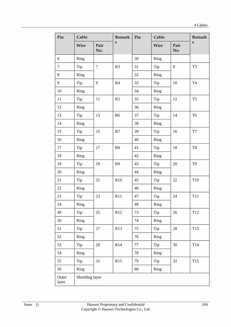
4 Cables
Issue () Huawei Proprietary and Confidential
Copyright © Huawei Technologies Co., Ltd.
104
Pin Cable Remarks
Pin Cable Remarks
Wire Pair No.
Wire Pair No.
6 Ring 30 Ring
7 Tip 7 R3 31 Tip 8 T3
8 Ring 32 Ring
9 Tip 9 R4 33 Tip 10 T4
10 Ring 34 Ring
11 Tip 11 R5 35 Tip 12 T5
12 Ring 36 Ring
13 Tip 13 R6 37 Tip 14 T6
14 Ring 38 Ring
15 Tip 15 R7 39 Tip 16 T7
16 Ring 40 Ring
17 Tip 17 R8 41 Tip 18 T8
18 Ring 42 Ring
19 Tip 19 R9 43 Tip 20 T9
20 Ring 44 Ring
21 Tip 21 R10 45 Tip 22 T10
22 Ring 46 Ring
23 Tip 23 R11 47 Tip 24 T11
24 Ring 48 Ring
49 Tip 25 R12 73 Tip 26 T12
50 Ring 74 Ring
51 Tip 27 R13 75 Tip 28 T13
52 Ring 76 Ring
53 Tip 29 R14 77 Tip 30 T14
54 Ring 78 Ring
55 Tip 31 R15 79 Tip 32 T15
56 Ring 80 Ring
Outer
layer
Shielding layer

4 Cables
Issue () Huawei Proprietary and Confidential
Copyright © Huawei Technologies Co., Ltd.
105
120-ohm 16xE1 cable wiring
Table 4-19 describes the wiring of the 120-ohm 16xE1 cable.
Table 4-19 120-ohm 16×E1 cable wiring
Pin Cable Remarks
Pin Cable Remarks
Wire Type Wire Type
1 White Twisted R0 25 White Twisted T0
2 Blue 26 Orange
3 White Twisted R1 27 White Twisted T1
4 Green 28 Brown
5 White Twisted R2 29 Red Twisted T2
6 Grey 30 Blue
7 Red Twisted R3 31 Red Twisted T3
8 Orange 32 Green
9 Red Twisted R4 33 Red Twisted T4
10 Brown 34 Grey
11 Black Twisted R5 35 Black Twisted T5
12 Blue 36 Orange
13 Black Twisted R6 37 Black Twisted T6
14 Green 38 Brown
15 Black Twisted R7 39 Yellow Twisted T7
16 Grey 40 Blue
17 White Twisted R8 41 White Twisted T8
18 Blue 42 Orange
19 White Twisted R9 43 White Twisted T9
20 Green 44 Brown
21 White Twisted R10 45 Red Twisted T10
22 Grey 46 Blue
23 Red Twisted R11 47 Red Twisted T11
24 Orange 48 Green
49 Red Twisted R12 73 Red Twisted T12
50 Brown 74 Grey
51 Black Twisted R13 75 Black Twisted T13
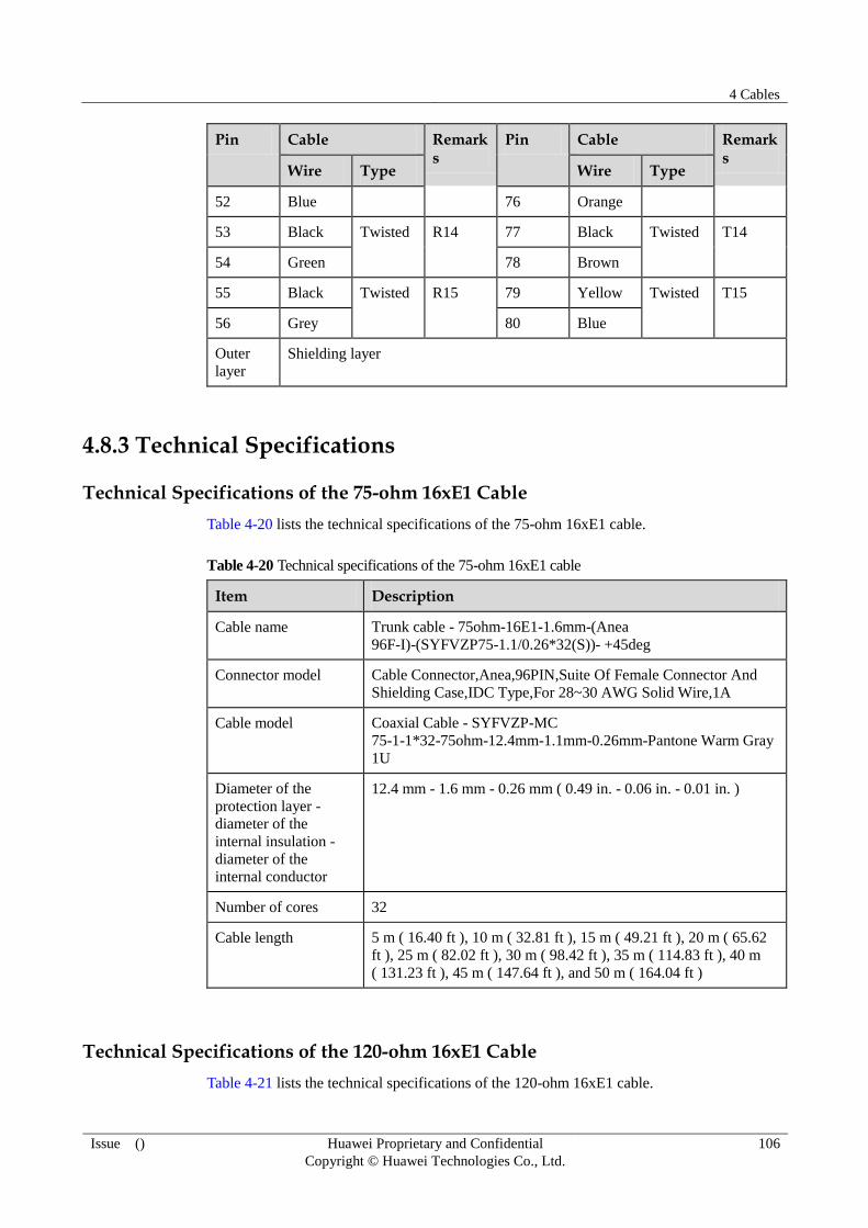
4 Cables
Issue () Huawei Proprietary and Confidential
Copyright © Huawei Technologies Co., Ltd.
106
Pin Cable Remarks
Pin Cable Remarks
Wire Type Wire Type
52 Blue 76 Orange
53 Black Twisted R14 77 Black Twisted T14
54 Green 78 Brown
55 Black Twisted R15 79 Yellow Twisted T15
56 Grey 80 Blue
Outer
layer
Shielding layer
4.8.3 Technical Specifications
Technical Specifications of the 75-ohm 16xE1 Cable
Table 4-20 lists the technical specifications of the 75-ohm 16xE1 cable.
Table 4-20 Technical specifications of the 75-ohm 16xE1 cable
Item Description
Cable name Trunk cable - 75ohm-16E1-1.6mm-(Anea
96F-I)-(SYFVZP75-1.1/0.26*32(S))- +45deg
Connector model Cable Connector,Anea,96PIN,Suite Of Female Connector And
Shielding Case,IDC Type,For 28~30 AWG Solid Wire,1A
Cable model Coaxial Cable - SYFVZP-MC
75-1-1*32-75ohm-12.4mm-1.1mm-0.26mm-Pantone Warm Gray
1U
Diameter of the
protection layer -
diameter of the
internal insulation -
diameter of the
internal conductor
12.4 mm - 1.6 mm - 0.26 mm ( 0.49 in. - 0.06 in. - 0.01 in. )
Number of cores 32
Cable length 5 m ( 16.40 ft ), 10 m ( 32.81 ft ), 15 m ( 49.21 ft ), 20 m ( 65.62
ft ), 25 m ( 82.02 ft ), 30 m ( 98.42 ft ), 35 m ( 114.83 ft ), 40 m
( 131.23 ft ), 45 m ( 147.64 ft ), and 50 m ( 164.04 ft )
Technical Specifications of the 120-ohm 16xE1 Cable
Table 4-21 lists the technical specifications of the 120-ohm 16xE1 cable.

4 Cables
Issue () Huawei Proprietary and Confidential
Copyright © Huawei Technologies Co., Ltd.
107
Table 4-21 Technical specifications of the 120-ohm 16xE1 cable
Item Description
Cable name Trunk cable - 120ohm-16E1-0.4mm-(Anea
96F-I)-(120CC32P0.4P430U(S))- +45deg
Connector model Cable Connector,Anea,96PIN,Suite Of Female Connector And
Shielding Case,IDC Type,For 24~26 AWG Solid Wire-1A
Cable model Twisted-Pair
Cable,120ohm,SEYVP,0.4mm,26AWG,32Pairs,Pantone 430U
Core diameter of the
internal conductor
0.4 mm ( 0.02 in. )
Number of cores 32 twisted pairs
Cable length 5 m ( 16.40 ft ), 10 m ( 32.81 ft ), 15 m ( 49.21 ft ), 20 m ( 65.62
ft ), 25 m ( 82.02 ft ), 30 m ( 98.42 ft ), 35 m (114.83 ft ), 40 m
( 131.23 ft ), 45 m (147.64 ft ), and 50 m (164.04 ft )
4.9 Alarm Input/Output Cables
This section describes the structure and technical specifications of the Alarm Input/Output
Cables.
4.9.1 Introduction
On the device, the RJ-45 connectors are used to input the alarm signals from the external
equipment and output the local alarm signals to the equipment that monitors all the alarms.
At one end of the alarm input/output cable, the RJ-45 connector is used to connect to the
ALMI or ALMO interface on the equipment; at the other end, a connector (made as required
on site) is used to connect to the external equipment or the equipment that monitors all the
alarms.
4.9.2 Structure
Structure
Figure 4-9 shows the structure of the alarm input/output cable.
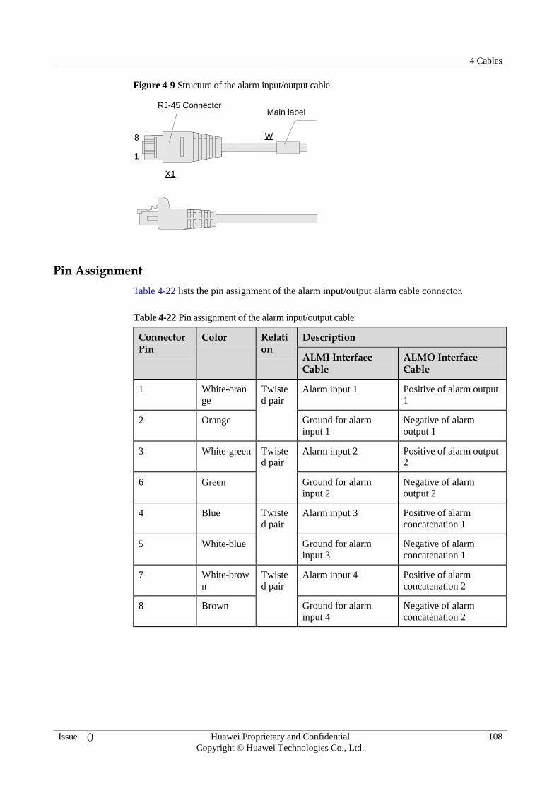
4 Cables
Issue () Huawei Proprietary and Confidential
Copyright © Huawei Technologies Co., Ltd.
108
Figure 4-9 Structure of the alarm input/output cable
W
X1
8
1
RJ-45 ConnectorMain label
Pin Assignment
Table 4-22 lists the pin assignment of the alarm input/output alarm cable connector.
Table 4-22 Pin assignment of the alarm input/output cable
Connector Pin
Color Relation
Description
ALMI Interface Cable
ALMO Interface Cable
1 White-oran
ge
Twiste
d pair
Alarm input 1 Positive of alarm output
1
2 Orange Ground for alarm
input 1
Negative of alarm
output 1
3 White-green Twiste
d pair Alarm input 2 Positive of alarm output
2
6 Green Ground for alarm
input 2
Negative of alarm
output 2
4 Blue Twiste
d pair
Alarm input 3 Positive of alarm
concatenation 1
5 White-blue Ground for alarm
input 3
Negative of alarm
concatenation 1
7 White-brow
n
Twiste
d pair
Alarm input 4 Positive of alarm
concatenation 2
8 Brown Ground for alarm
input 4
Negative of alarm
concatenation 2
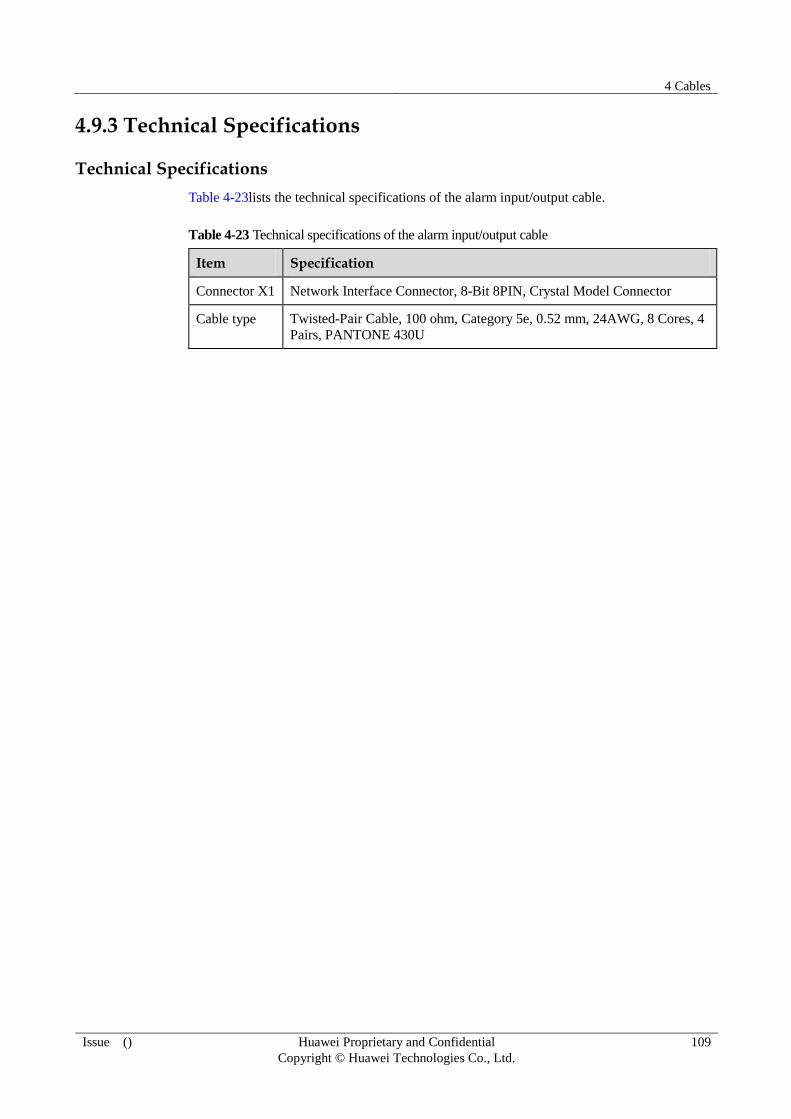
4 Cables
Issue () Huawei Proprietary and Confidential
Copyright © Huawei Technologies Co., Ltd.
109
4.9.3 Technical Specifications
Technical Specifications
Table 4-23lists the technical specifications of the alarm input/output cable.
Table 4-23 Technical specifications of the alarm input/output cable
Item Specification
Connector X1 Network Interface Connector, 8-Bit 8PIN, Crystal Model Connector
Cable type Twisted-Pair Cable, 100 ohm, Category 5e, 0.52 mm, 24AWG, 8 Cores, 4
Pairs, PANTONE 430U

A List of Indicators
Issue () Huawei Proprietary and Confidential
Copyright © Huawei Technologies Co., Ltd.
110
A List of Indicators
This chapter presents the list of indicators.
A.1 Indicators on the NE40E-X1
This section describes the indicators on the NE40E-X1.
A.2 Indicators on the NE40E-X2
This section describes the indicators on the NE40E-X2.
A.1 Indicators on the NE40E-X1
This section describes the indicators on the NE40E-X1.
A.1.1 Indicators on a Fan Module
Table A-1 describes the indicators on a fan module.
Table A-1 Description of the indicators on a fan module
Indicator Color Description
FAN Green If the indicator is steady green, it
indicates that the fan module works
normally.
If the indicator is off, it indicates that the
fan module fails to be unregistered, is
not powered on, or has a hardware fault.
Red If the indicator is steady red, it indicates
that the fan module is faulty.
A.1.2 Indicators on a PSU
The indicators of the PSU are located on the plastic panel. Table A-2 describes the indicators
on a DC PSU.

A List of Indicators
Issue () Huawei Proprietary and Confidential
Copyright © Huawei Technologies Co., Ltd.
111
Table A-2 Description of the indicators on a DC PSU
Indicator Color Description
IN Green If the indicator is steady green, it indicates that the
power input is normal.
If the indicator is off, it indicates that the device is not
supplied with -48 V or -60 V power.
OUT Green If the indicator is steady green, it indicates that the DC
PSU works normally and supplies stable power.
If the indicator is off, it indicates that the DC PSU is
switched off or has a hardware fault.
Red If indicator is steady red, it indicates that the hardware
of the DC PSU fails or the device is not supplied with
-48 V or -60 V power.
A.1.3 Indicators on an MPU
Table A-3 describes the indicators on an MPU.
Table A-3 Description of the buttons and indicators on the MPU panel
Indicator/Button
Status Description
STAT
indicator
Green If the indicator is steady green, it indicates that the MPU
works normally.
If the indicator blinks green, it indicates that the MPU is
being registered.
If the indicator is off, it indicates that the MPU is not
powered on or fails to be registered.
Red If the indicator is steady red, it indicates that the hardware
of the MPU is faulty.
ACT
indicator
Green If the indicator is steady green, it indicates that the MPU
functions as the master MPU.
If the indicator is off, it indicates that the MPU functions as
the slave MPU or fails to be registered.
USB
indicator
Green If the indicator is steady green, it indicates that a mobile
storage device can be identified.
If the indicator blinks, it indicates that a mobile storage
device is being accessed or written.
If the indicator is off, it indicates that the USB interface is
not installed with a mobile storage device.
Red If the indicator is steady red, it indicates that a mobile
storage device cannot be identified or fails to be accessed or
written.

A List of Indicators
Issue () Huawei Proprietary and Confidential
Copyright © Huawei Technologies Co., Ltd.
112
Indicator/Button
Status Description
ETH LINK
indicator
Green If the indicator is steady green, it indicates that the ETH link
is Up.
If the indicator is off, it indicates that the ETH link is Down.
ETH ACT
indicator
Yellow If the indicator blinks yellow, it indicates that data is being
transmitted.
If the indicator is off, it indicates that no data is being
transmitted.
RST button - The button is used for resetting the MPU. Pressing the RST
button resets the MPU.
A.1.4 Indicators on an NPU
Table A-4 describes the indicators on an NPU.
Table A-4 Description of the buttons and indicators on the NPU panel
Indicator/Button Status Description
STAT indicator Green If the indicator is steady green, it indicates that the
NPU works normally.
If the indicator blinks green, it indicates that the
NPU is being registered.
If the indicator is off, it indicates that the NPU is
not powered on or fails to be registered.
Red If the indicator is steady red, it indicates that the
hardware of the NPU is faulty.
ACT indicator Green If the indicator is steady green, it indicates that the
NPU is in the master state.
If the indicator is off, it indicates that the NPU is in
the slave state or fails to be registered.
OFL indicator Red If the indicator is steady red, it indicates that the
NPU is powered off and can be safely removed.
If the indicator is off, it indicates that the NPU
works normally.
L/A0 indicator Green If the indicator is steady green, it indicates that the
corresponding link is Up.
If the indicator blinks, it indicates that data is being
transmitted.
If the indicator is off, it indicates that the
corresponding link is Down.
L/A1 indicator Green If the indicator is steady green, it indicates that the
corresponding link is Up.
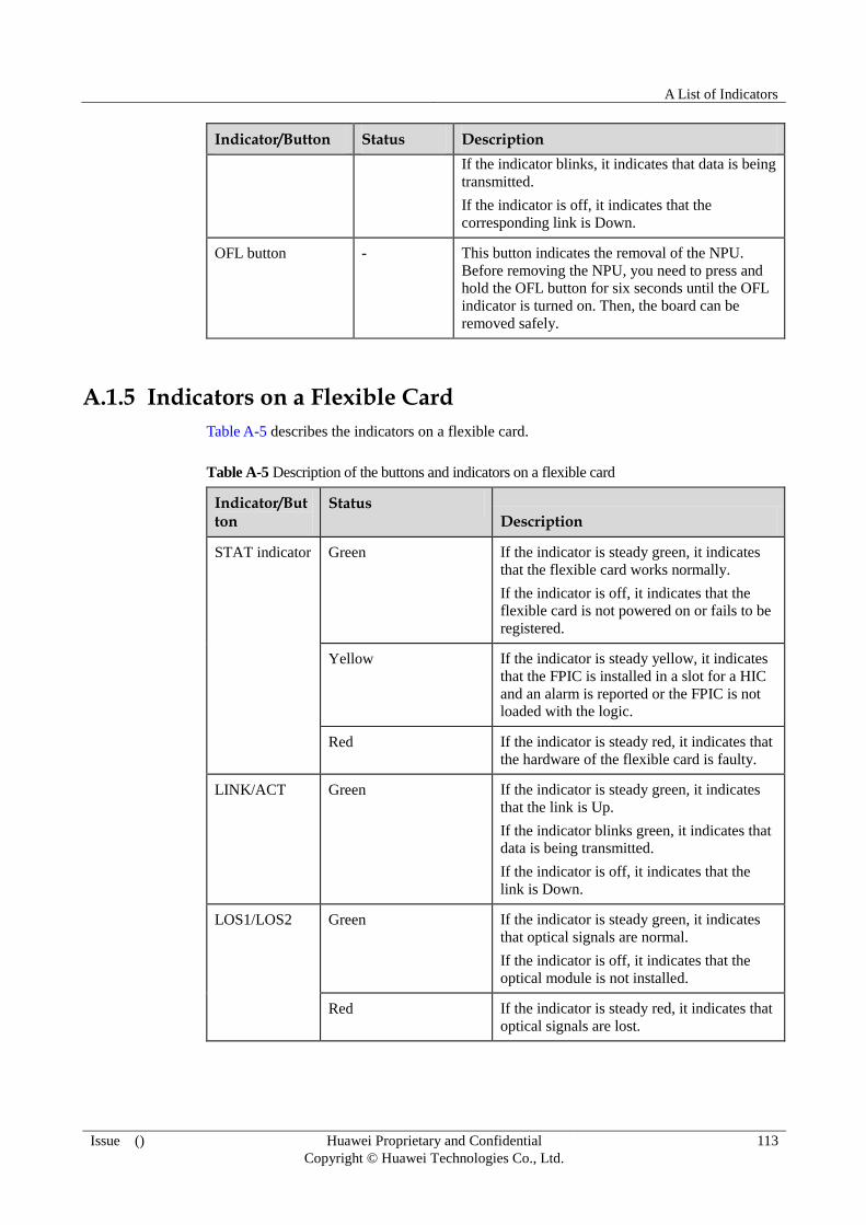
A List of Indicators
Issue () Huawei Proprietary and Confidential
Copyright © Huawei Technologies Co., Ltd.
113
Indicator/Button Status Description
If the indicator blinks, it indicates that data is being
transmitted.
If the indicator is off, it indicates that the
corresponding link is Down.
OFL button - This button indicates the removal of the NPU.
Before removing the NPU, you need to press and
hold the OFL button for six seconds until the OFL
indicator is turned on. Then, the board can be
removed safely.
A.1.5 Indicators on a Flexible Card
Table A-5 describes the indicators on a flexible card.
Table A-5 Description of the buttons and indicators on a flexible card
Indicator/Button
Status Description
STAT indicator Green If the indicator is steady green, it indicates
that the flexible card works normally.
If the indicator is off, it indicates that the
flexible card is not powered on or fails to be
registered.
Yellow If the indicator is steady yellow, it indicates
that the FPIC is installed in a slot for a HIC
and an alarm is reported or the FPIC is not
loaded with the logic.
Red If the indicator is steady red, it indicates that
the hardware of the flexible card is faulty.
LINK/ACT Green If the indicator is steady green, it indicates
that the link is Up.
If the indicator blinks green, it indicates that
data is being transmitted.
If the indicator is off, it indicates that the
link is Down.
LOS1/LOS2 Green If the indicator is steady green, it indicates
that optical signals are normal.
If the indicator is off, it indicates that the
optical module is not installed.
Red If the indicator is steady red, it indicates that
optical signals are lost.

A List of Indicators
Issue () Huawei Proprietary and Confidential
Copyright © Huawei Technologies Co., Ltd.
114
A.2 Indicators on the NE40E-X2
This section describes the indicators on the NE40E-X2.
A.2.1 Fan Module Indicators
Table A-6 describes the indicators on a fan module.
Table A-6 Description of the indicators on a fan module
Indicator Color Description
FAN Green If the indicator is steady green, it
indicates that the fan module works
normally.
If the indicator is off, it indicates that the
fan module fails to be unregistered, is
not powered on, or has a hardware fault.
Red If the indicator is steady red, it indicates
that the fan module is faulty.
A.2.2 Power Module Indicators
The indicators of the PSU are located on the plastic panel. Table A-7 describes the indicators
on a DC PSU.
Table A-7 Description of the indicators on a DC PSU
Indicator Color Description
IN Green If the indicator is steady green, it indicates that the
power input is normal.
If the indicator is off, it indicates that the device is not
supplied with -48 V or -60 V power.
OUT Green If the indicator is steady green, it indicates that the DC
PSU works normally and supplies stable power.
If the indicator is off, it indicates that the DC PSU is
switched off or has a hardware fault.
Red If indicator is steady red, it indicates that the hardware
of the DC PSU fails or the device is not supplied with
-48 V or -60 V power.
A.2.3 MPU Indicators
Table A-8 describes the indicators on an MPU.

A List of Indicators
Issue () Huawei Proprietary and Confidential
Copyright © Huawei Technologies Co., Ltd.
115
Table A-8 Description of the buttons and indicators on the MPU panel
Indicator/Button
Status Description
STAT
indicator
Green If the indicator is steady green, it indicates that the MPU
works normally.
If the indicator blinks green, it indicates that the MPU is
being registered.
If the indicator is off, it indicates that the MPU is not
powered on or fails to be registered.
Red If the indicator is steady red, it indicates that the hardware
of the MPU is faulty.
ACT
indicator
Green If the indicator is steady green, it indicates that the MPU
functions as the master MPU.
If the indicator is off, it indicates that the MPU functions as
the slave MPU or fails to be registered.
USB
indicator
Green If the indicator is steady green, it indicates that a mobile
storage device can be identified.
If the indicator blinks, it indicates that a mobile storage
device is being accessed or written.
If the indicator is off, it indicates that the USB interface is
not installed with a mobile storage device.
Red If the indicator is steady red, it indicates that a mobile
storage device cannot be identified or fails to be accessed or
written.
ETH LINK
indicator
Green If the indicator is steady green, it indicates that the ETH link
is Up.
If the indicator is off, it indicates that the ETH link is Down.
ETH ACT
indicator
Yellow If the indicator blinks yellow, it indicates that data is being
transmitted.
If the indicator is off, it indicates that no data is being
transmitted.
RST button - The button is used for resetting the MPU. Pressing the RST
button resets the MPU.
A.2.4 NPU Indicators
Table A-9 describes the indicators on an NPU.
Table A-9 Description of the buttons and indicators on the NPU panel
Indicator/Button Status Description
STAT indicator Green If the indicator is steady green, it indicates that the
NPU works normally.

A List of Indicators
Issue () Huawei Proprietary and Confidential
Copyright © Huawei Technologies Co., Ltd.
116
Indicator/Button Status Description
If the indicator blinks green, it indicates that the
NPU is being registered.
If the indicator is off, it indicates that the NPU is
not powered on or fails to be registered.
Red If the indicator is steady red, it indicates that the
hardware of the NPU is faulty.
ACT indicator Green If the indicator is steady green, it indicates that the
NPU is in the master state.
If the indicator is off, it indicates that the NPU is in
the slave state or fails to be registered.
OFL indicator Red If the indicator is steady red, it indicates that the
NPU is powered off and can be safely removed.
If the indicator is off, it indicates that the NPU
works normally.
L/A0 indicator Green If the indicator is steady green, it indicates that the
corresponding link is Up.
If the indicator blinks, it indicates that data is being
transmitted.
If the indicator is off, it indicates that the
corresponding link is Down.
L/A1 indicator Green If the indicator is steady green, it indicates that the
corresponding link is Up.
If the indicator blinks, it indicates that data is being
transmitted.
If the indicator is off, it indicates that the
corresponding link is Down.
OFL button - This button indicates the removal of the NPU.
Before removing the NPU, you need to press and
hold the OFL button for six seconds until the OFL
indicator is turned on. Then, the board can be
removed safely.
A.2.5 FIC Indicators
Table A-10 describes the indicators on a flexible card.
Table A-10 Description of the buttons and indicators on a flexible card
Indicator/Button
Status Description
STAT indicator Green If the indicator is steady green, it indicates
that the flexible card works normally.
If the indicator is off, it indicates that the
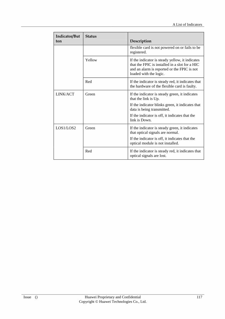
A List of Indicators
Issue () Huawei Proprietary and Confidential
Copyright © Huawei Technologies Co., Ltd.
117
Indicator/Button
Status Description
flexible card is not powered on or fails to be
registered.
Yellow If the indicator is steady yellow, it indicates
that the FPIC is installed in a slot for a HIC
and an alarm is reported or the FPIC is not
loaded with the logic.
Red If the indicator is steady red, it indicates that
the hardware of the flexible card is faulty.
LINK/ACT Green If the indicator is steady green, it indicates
that the link is Up.
If the indicator blinks green, it indicates that
data is being transmitted.
If the indicator is off, it indicates that the
link is Down.
LOS1/LOS2 Green If the indicator is steady green, it indicates
that optical signals are normal.
If the indicator is off, it indicates that the
optical module is not installed.
Red If the indicator is steady red, it indicates that
optical signals are lost.

B List of Boards
Issue () Huawei Proprietary and Confidential
Copyright © Huawei Technologies Co., Ltd.
118
B List of Boards
This chapter presents the list of boards.
B.1 List of Boards
B.2 Board Power Consumption and Weight
B.1 List of Boards
Table B-1 shows the basic configurations of the NE40E. Table B-2 lists the physical interface
cards supported by the NE40E.
Table B-1 Basic configurations
Product Name
BOM Number
Order Name Full Name
NE40E-X1 02352442 CR5B0BKP0170 NE40E-X1 integrated chassis
components
03030MPH CR5D00MPUG7
0
Main Processing Unit
03030MPL CR5DNPUI2070 Network Processing Unit
02310ANF CR5M001FBX70 FAN Module
03030MGE CR5D00PSUD70 DC Power Supply Module
NE40E-X2 02352447 CR5B0BKP0270 NE40E-X2 integrated chassis
components
03030MPH CR5D00MPUG7
0
Main Processing Unit
03030MPL CR5DNPUI2070 Network Processing Unit
02310ANG CR5M002FBX70 FAN Module
03030MGE CR5D00PSUD70 DC Power Supply Module

B List of Boards
Issue () Huawei Proprietary and Confidential
Copyright © Huawei Technologies Co., Ltd.
119
Table B-2 Flexible cards
Board Type
BOM Number
Order Name Full Name
PIC 03030MEK CR5D00E8GF7
0
8-Port 100/1000Base-X-SFP
High-speed Interface Card (HIC)
03030NLS CR5D0E8GFA
71
8-Port 100/1000Base-X-SFP
High-speed Interface Card A
(HIC,Supporting 1588v2)
03030NRP CR5D00E4GF7
0
4-Port 100/1000Base-X-SFP
High-speed Interface Card(HIC)
03030PCB CR5D00P4CF7
0
4-Port OC-3c/STM-1c POS-SFP
Flexible Interface Card (FIC)
03030MEM CR5D00E8FF1
0
8-Port 100Base-X-SFP Flexible
Interface Card (FIC,Supporting
1588v2)
03030MEN CR5D00E8FE1
0
8-Port 100Base-X-RJ45 Flexible
Interface Card (FIC,Supporting
1588v2)
03030MEP CR5D000DE11
0
16-Port E1 Flexible Interface
Card(FIC,75ohms)
03030MEQ CR5D000DE11
1
16-Port E1 Flexible Interface
Card(FIC,120ohms)
03030MER CR5D00AUXQ
10
Auxiliary Flexible Interface Card
with 4-Port 100Base-RJ45
(FIC,Supporting 1588v2)
03030MES CR5D00C1CF1
0
1-Port Channelized OC-3c/STM-1c
POS-SFP Flexible Interface Card (FIC)
03030NED CR5D00A4CF7
0
4-Port OC-3c/STM-1c ATM SFP
Flexible Interface Card (FIC)
B.2 Board Power Consumption and Weight
Table B-3 lists the nominal power consumption and weight of each type of board supported
by the NE40E.
Table B-3 board power consumption and weight
Full Name Power Consumption
Heat Dissipation
Weight
Main process Unit MPUG 24 W 78 BTU/hour 0.64 kg ( 1.41
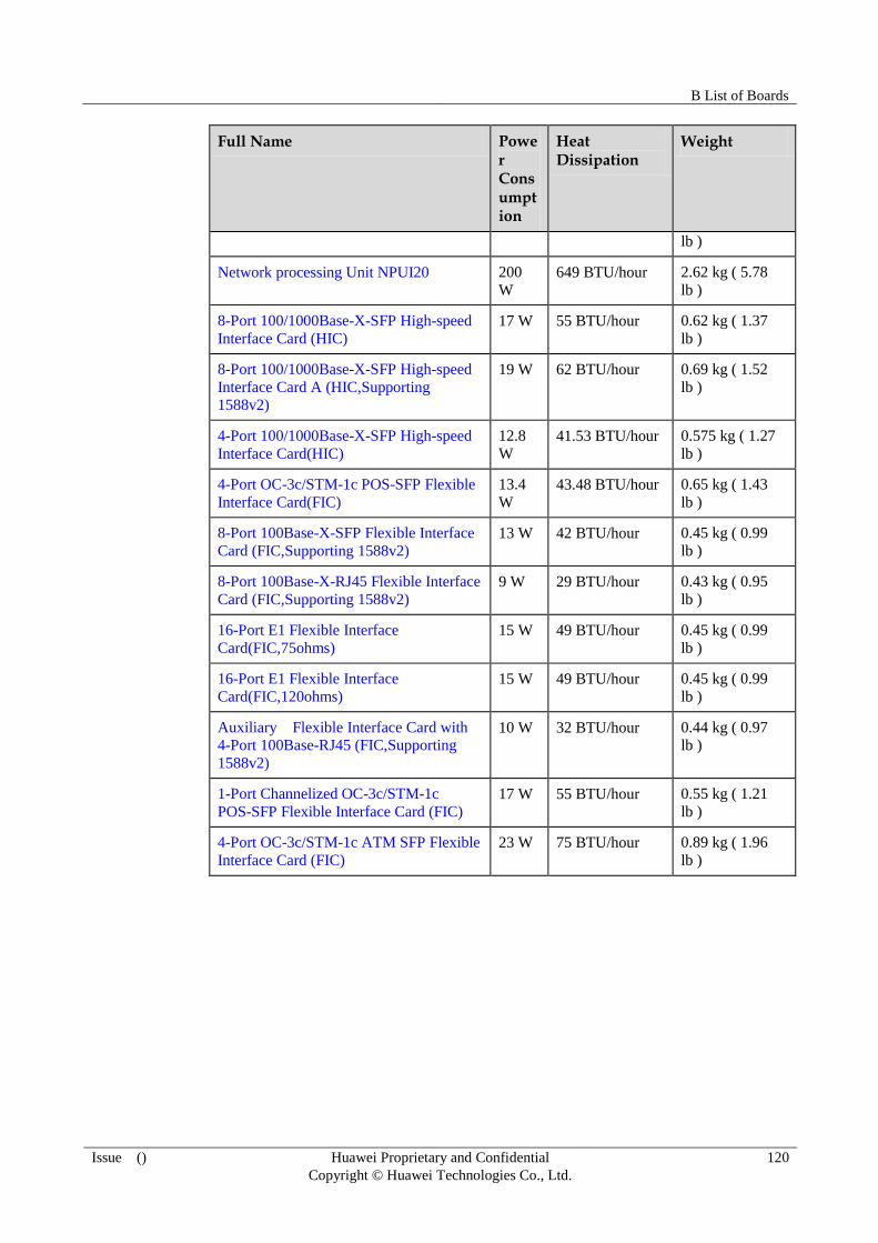
B List of Boards
Issue () Huawei Proprietary and Confidential
Copyright © Huawei Technologies Co., Ltd.
120
Full Name Power Consumption
Heat Dissipation
Weight
lb )
Network processing Unit NPUI20 200
W
649 BTU/hour 2.62 kg ( 5.78
lb )
8-Port 100/1000Base-X-SFP High-speed
Interface Card (HIC)
17 W 55 BTU/hour 0.62 kg ( 1.37
lb )
8-Port 100/1000Base-X-SFP High-speed
Interface Card A (HIC,Supporting
1588v2)
19 W 62 BTU/hour 0.69 kg ( 1.52
lb )
4-Port 100/1000Base-X-SFP High-speed
Interface Card(HIC)
12.8
W
41.53 BTU/hour 0.575 kg ( 1.27
lb )
4-Port OC-3c/STM-1c POS-SFP Flexible
Interface Card(FIC)
13.4
W
43.48 BTU/hour 0.65 kg ( 1.43
lb )
8-Port 100Base-X-SFP Flexible Interface
Card (FIC,Supporting 1588v2)
13 W 42 BTU/hour 0.45 kg ( 0.99
lb )
8-Port 100Base-X-RJ45 Flexible Interface
Card (FIC,Supporting 1588v2)
9 W 29 BTU/hour 0.43 kg ( 0.95
lb )
16-Port E1 Flexible Interface
Card(FIC,75ohms)
15 W 49 BTU/hour 0.45 kg ( 0.99
lb )
16-Port E1 Flexible Interface
Card(FIC,120ohms)
15 W 49 BTU/hour 0.45 kg ( 0.99
lb )
Auxiliary Flexible Interface Card with
4-Port 100Base-RJ45 (FIC,Supporting
1588v2)
10 W 32 BTU/hour 0.44 kg ( 0.97
lb )
1-Port Channelized OC-3c/STM-1c
POS-SFP Flexible Interface Card (FIC)
17 W 55 BTU/hour 0.55 kg ( 1.21
lb )
4-Port OC-3c/STM-1c ATM SFP Flexible
Interface Card (FIC)
23 W 75 BTU/hour 0.89 kg ( 1.96
lb )
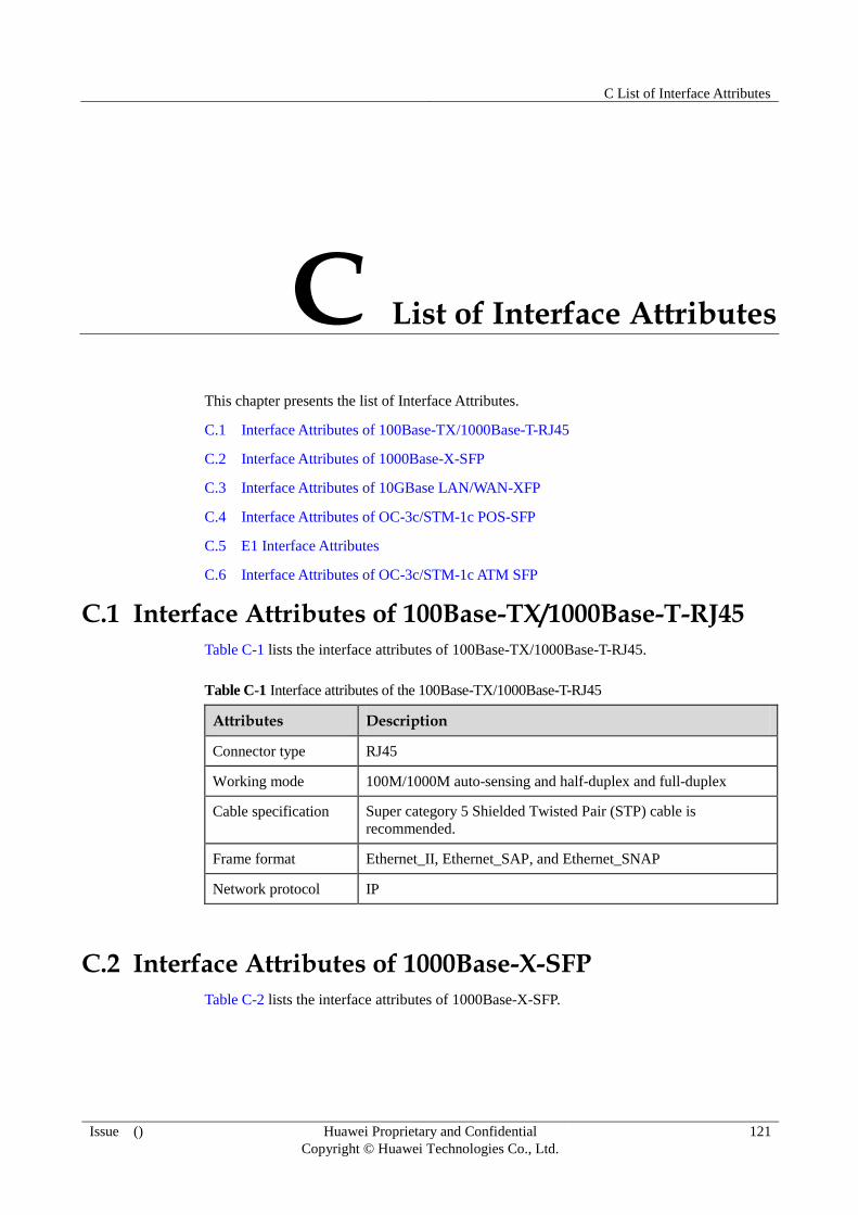
C List of Interface Attributes
Issue () Huawei Proprietary and Confidential
Copyright © Huawei Technologies Co., Ltd.
121
C List of Interface Attributes
This chapter presents the list of Interface Attributes.
C.1 Interface Attributes of 100Base-TX/1000Base-T-RJ45
C.2 Interface Attributes of 1000Base-X-SFP
C.3 Interface Attributes of 10GBase LAN/WAN-XFP
C.4 Interface Attributes of OC-3c/STM-1c POS-SFP
C.5 E1 Interface Attributes
C.6 Interface Attributes of OC-3c/STM-1c ATM SFP
C.1 Interface Attributes of 100Base-TX/1000Base-T-RJ45
Table C-1 lists the interface attributes of 100Base-TX/1000Base-T-RJ45.
Table C-1 Interface attributes of the 100Base-TX/1000Base-T-RJ45
Attributes Description
Connector type RJ45
Working mode 100M/1000M auto-sensing and half-duplex and full-duplex
Cable specification Super category 5 Shielded Twisted Pair (STP) cable is
recommended.
Frame format Ethernet_II, Ethernet_SAP, and Ethernet_SNAP
Network protocol IP
C.2 Interface Attributes of 1000Base-X-SFP
Table C-2 lists the interface attributes of 1000Base-X-SFP.

C List of Interface Attributes
Issue () Huawei Proprietary and Confidential
Copyright © Huawei Technologies Co., Ltd.
122
Table C-2 Interface attributes of the 1000Base-X-SFP
Attributes Description
Connector type LC/PC
Interface attributes Compliant with the selected SFP optical module. (For the
attributes of SFP modules, see Table C-3 .)
Working mode Full-duplex
Frame format Ethernet_II, Ethernet_SAP, and Ethernet_SNAP
Network protocol IP
Table C-3 Attributes of 1000M SFP optical modules
Attributes Description
Transmission
distance
0.5 km
( 0.31
mi. )
10 km
( 6.21
mi. )
40 km
( 24.86
mi. )
40 km
( 24.86
mi. )
80 km
( 49.71
mi. )
100 km
( 62.14
mi. )
Center
wavelength
850 nm 1310 nm 1310 nm 1550 nm 1550
nm
1550 nm
Minimum
transmitting
power
-9.5 dBm -9.5 dBm -4.5 dBm -4.0 dBm -2.0
dBm
0 dBm
Maximum
transmitting
power
-2.5 dBm -3.0 dBm 3.0 dBm 1.0 dBm 5.0
dBm 5.0 dBm
Receiving
sensitivity
-17.0
dBm
-20.0
dBm
-22.5
dBm
-21.0
dBm
-23.0
dBm
-30.0
dBm
Overload power 0 dBm -3.0 dBm -3.0 dBm -3.0 dBm -3.0
dBm
-9.0 dBm
Optical fiber type Multi-mo
de
Single-m
ode
Single-m
ode
Single-m
ode
Single-
mode
Single-m
ode
C.3 Interface Attributes of 10GBase LAN/WAN-XFP
The interface attributes of 10GBase LAN/WAN-XFP see Table C-4.
Table C-4 Interface attributes of the 10GBase LAN/WAN-XFP
Attributes Description
Connector type LC/PC
Interface attributes Compliant with the selected XFP optical module. (For the

C List of Interface Attributes
Issue () Huawei Proprietary and Confidential
Copyright © Huawei Technologies Co., Ltd.
123
Attributes Description
attributes of XFP modules, see Table C-5.)
Working mode Full-duplex
Frame format Ethernet_II, Ethernet_SAP, and Ethernet_SNAP
Network protocol IP
Table C-5 Attributes of 10G XFP optical modules
Attributes Description
Transmission
distance
0.3 km ( 0.19
mi. )
10 km ( 6.21
mi. )
40 km ( 24.86
mi. )
80 km ( 49.71
mi. )
Center
wavelength
850 nm 1310 nm 1550 nm 1550 nm
Minimum
transmitting
power
-7.3 dBm -6.0 dBm -1.0 dBm 0 dBm
Maximum
transmitting
power
-1.3 dBm -1.0 dBm 2.0 dBm 4.0 dBm
Receiving
sensitivity
-7.5 dBm -11.0 dBm -15.0 dBm -24.0 dBm
Overload
power
-1.0 dBm 0.5 dBm -1.0 dBm -7.0 dBm
Optical fiber
type
Multi-mode Single-mode Single-mode Single-mode
C.4 Interface Attributes of OC-3c/STM-1c POS-SFP
Table C-6 lists the interface attributes of OC-3c/STM-1c POS-SFP.
Table C-6 Interface attributes of the OC-3c/STM-1c POS-SFP
Attributes Description
Connector type LC/PC
Interface attributes Compliant with the selected SFP optical module. (For the
attributes of SFP modules, see Table C-7.)
Working mode Full-duplex
Link protocol PPP and HDLC

C List of Interface Attributes
Issue () Huawei Proprietary and Confidential
Copyright © Huawei Technologies Co., Ltd.
124
Attributes Description
Network protocol IP
Table C-7 Attributes of 155M SFP optical modules
Attributes Description
Transmission
distance
2 km ( 1.24
mi. )
15 km ( 9.32
mi. )
40 km ( 24.86
mi. )
80 km ( 49.71
mi. )
Center
wavelength
1310 nm 1310 nm 1310 nm 1550 nm
Minimum
transmitting
power
-19.0 dBm -15.0 dBm -5.0 dBm -5.0 dBm
Maximum
transmitting
power
-14.0 dBm -8.0 dBm 0 dBm 0 dBm
Receiving
sensitivity
-30.0 dBm -31.0 dBm -37.0 dBm -37.0 dBm
Overload
power
-14.0 dBm -8.0 dBm -10.0 dBm -10.0 dBm
Optical fiber
type
Multi-mode Single-mode Single-mode Single-mode
C.5 E1 Interface Attributes
Table C-8 lists E1 interface attributes.
Table C-8 E1 interface attributes
Attribute Description
Connector type Anea96
Nominal bit rate
(kbit/s)
2048
Interface
impedance
75-ohm with coaxial cable.
120-ohm with twisted-pair cable.
Interface code HDB3
Pulse waveform
of the output
interface
Compliant with ITU-T G.703
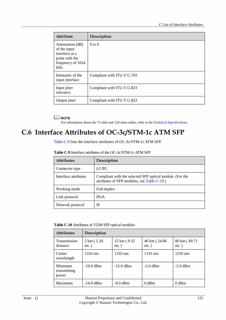
C List of Interface Attributes
Issue () Huawei Proprietary and Confidential
Copyright © Huawei Technologies Co., Ltd.
125
Attribute Description
Attenuation (dB)
of the input
interface at a
point with the
frequency of 1024
kHz
0 to 6
Immunity of the
input interface
Compliant with ITU-T G.703
Input jitter
tolerance
Compliant with ITU-T G.823
Output jitter Compliant with ITU-T G.823
For information about the 75-ohm and 120-ohm cables, refer to the Technical Specifications.
C.6 Interface Attributes of OC-3c/STM-1c ATM SFP
Table C-9 lists the interface attributes of OC-3c/STM-1c ATM SFP.
Table C-9 Interface attributes of the OC-3c/STM-1c ATM SFP
Attributes Description
Connector type LC/PC
Interface attributes Compliant with the selected SFP optical module. (For the
attributes of SFP modules, see Table C-10.)
Working mode Full-duplex
Link protocol IPoA
Network protocol IP
Table C-10 Attributes of 155M SFP optical modules
Attributes Description
Transmission
distance
2 km ( 1.24
mi. )
15 km ( 9.32
mi. )
40 km ( 24.86
mi. )
80 km ( 49.71
mi. )
Center
wavelength
1310 nm 1310 nm 1310 nm 1550 nm
Minimum
transmitting
power
-19.0 dBm -15.0 dBm -5.0 dBm -5.0 dBm
Maximum -14.0 dBm -8.0 dBm 0 dBm 0 dBm
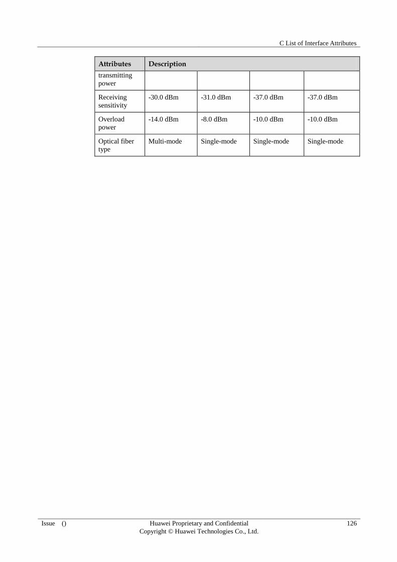
C List of Interface Attributes
Issue () Huawei Proprietary and Confidential
Copyright © Huawei Technologies Co., Ltd.
126
Attributes Description
transmitting
power
Receiving
sensitivity
-30.0 dBm -31.0 dBm -37.0 dBm -37.0 dBm
Overload
power
-14.0 dBm -8.0 dBm -10.0 dBm -10.0 dBm
Optical fiber
type Multi-mode Single-mode Single-mode Single-mode
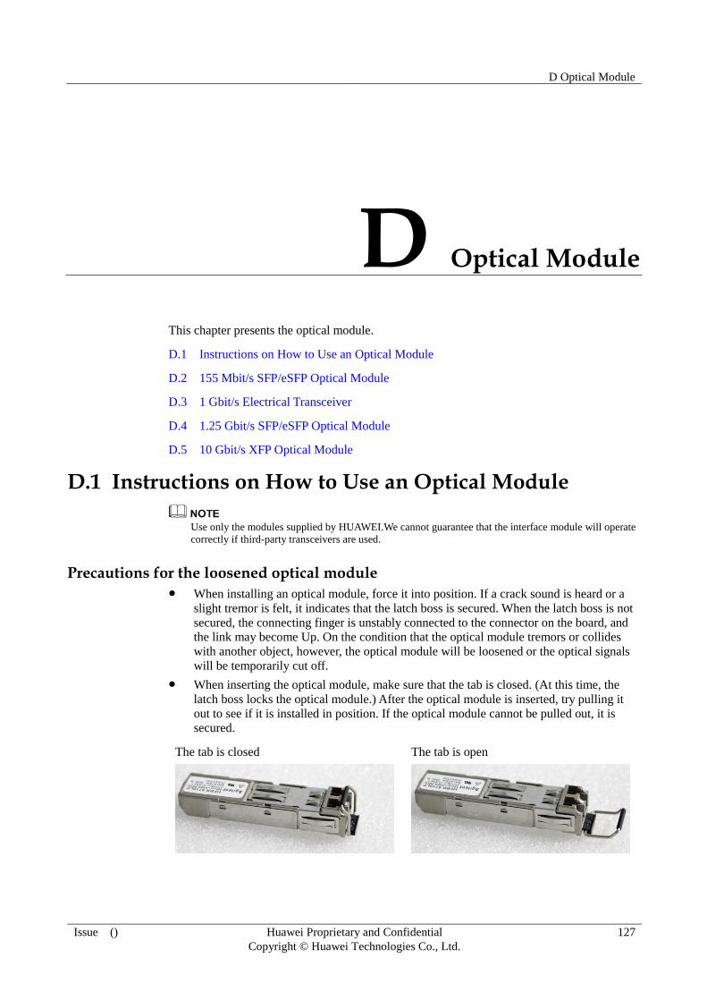
D Optical Module
Issue () Huawei Proprietary and Confidential
Copyright © Huawei Technologies Co., Ltd.
127
D Optical Module
This chapter presents the optical module.
D.1 Instructions on How to Use an Optical Module
D.2 155 Mbit/s SFP/eSFP Optical Module
D.3 1 Gbit/s Electrical Transceiver
D.4 1.25 Gbit/s SFP/eSFP Optical Module
D.5 10 Gbit/s XFP Optical Module
D.1 Instructions on How to Use an Optical Module
Use only the modules supplied by HUAWEI.We cannot guarantee that the interface module will operate
correctly if third-party transceivers are used.
Precautions for the loosened optical module When installing an optical module, force it into position. If a crack sound is heard or a
slight tremor is felt, it indicates that the latch boss is secured. When the latch boss is not
secured, the connecting finger is unstably connected to the connector on the board, and
the link may become Up. On the condition that the optical module tremors or collides
with another object, however, the optical module will be loosened or the optical signals
will be temporarily cut off.
When inserting the optical module, make sure that the tab is closed. (At this time, the
latch boss locks the optical module.) After the optical module is inserted, try pulling it
out to see if it is installed in position. If the optical module cannot be pulled out, it is
secured.
The tab is closed
The tab is open
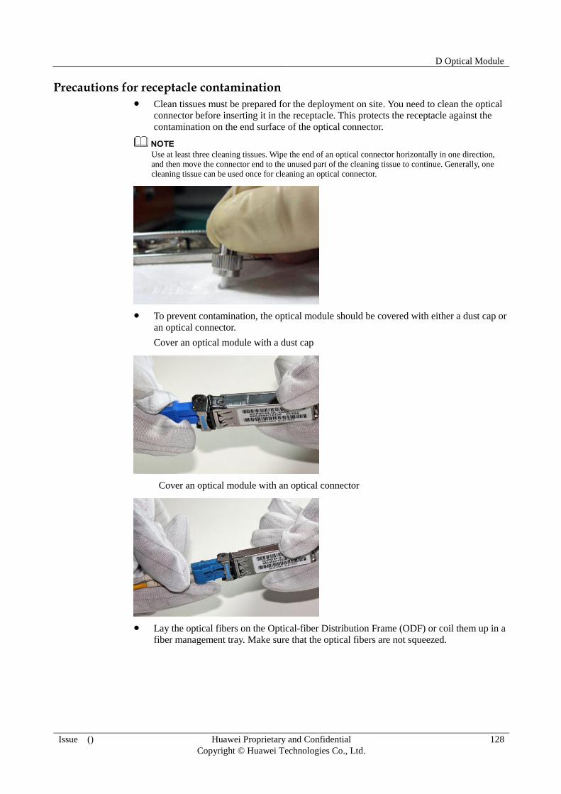
D Optical Module
Issue () Huawei Proprietary and Confidential
Copyright © Huawei Technologies Co., Ltd.
128
Precautions for receptacle contamination Clean tissues must be prepared for the deployment on site. You need to clean the optical
connector before inserting it in the receptacle. This protects the receptacle against the
contamination on the end surface of the optical connector.
Use at least three cleaning tissues. Wipe the end of an optical connector horizontally in one direction,
and then move the connector end to the unused part of the cleaning tissue to continue. Generally, one
cleaning tissue can be used once for cleaning an optical connector.
To prevent contamination, the optical module should be covered with either a dust cap or
an optical connector.
Cover an optical module with a dust cap
Cover an optical module with an optical connector
Lay the optical fibers on the Optical-fiber Distribution Frame (ODF) or coil them up in a
fiber management tray. Make sure that the optical fibers are not squeezed.
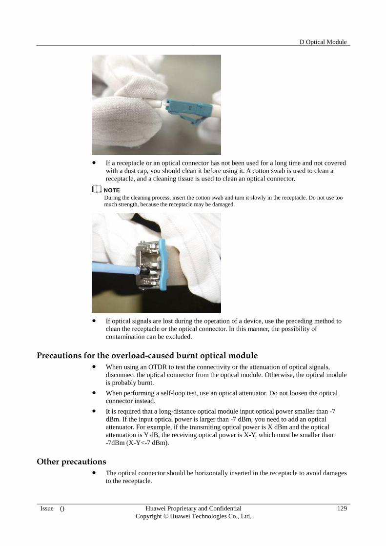
D Optical Module
Issue () Huawei Proprietary and Confidential
Copyright © Huawei Technologies Co., Ltd.
129
If a receptacle or an optical connector has not been used for a long time and not covered
with a dust cap, you should clean it before using it. A cotton swab is used to clean a
receptacle, and a cleaning tissue is used to clean an optical connector.
During the cleaning process, insert the cotton swab and turn it slowly in the receptacle. Do not use too
much strength, because the receptacle may be damaged.
If optical signals are lost during the operation of a device, use the preceding method to
clean the receptacle or the optical connector. In this manner, the possibility of
contamination can be excluded.
Precautions for the overload-caused burnt optical module When using an OTDR to test the connectivity or the attenuation of optical signals,
disconnect the optical connector from the optical module. Otherwise, the optical module
is probably burnt.
When performing a self-loop test, use an optical attenuator. Do not loosen the optical
connector instead.
It is required that a long-distance optical module input optical power smaller than -7
dBm. If the input optical power is larger than -7 dBm, you need to add an optical
attenuator. For example, if the transmiting optical power is X dBm and the optical
attenuation is Y dB, the receiving optical power is X-Y, which must be smaller than
-7dBm (X-Y<-7 dBm).
Other precautions The optical connector should be horizontally inserted in the receptacle to avoid damages
to the receptacle.

D Optical Module
Issue () Huawei Proprietary and Confidential
Copyright © Huawei Technologies Co., Ltd.
130
Mixed use of multi-mode and single-mode optical fibers is prohibited. Otherwise, faults
such as signal loss may occur.
D.2 155 Mbit/s SFP/eSFP Optical Module
The STM-1 SFP optical module, with the transmission rate ranging from 100 Mbit/s to 155
Mbit/s, the wavelength being 1310 nm or 1550 nm, and the transmission distance ranging
from 2 km ( 1.24 mi. ) to 100 km ( 62.14 mi. ), can be applied to the STM-1/OC-3 POS
interface, ATM interface, or FE optical interface .
Table D-1 lists the currently available 155 Mbit/s SFP/eSFP optical modules.
Table D-1 155 Mbit/s SFP/eSFP Optical Modules
Product Model
BOM Number
Interface Standard
Transmission Distance(km)
Mode Wavelength (nm)
Remarks
SFP-STM
1-MM131
0-2Km
34060287 STM-1 I-1 2 ( 1.24
mi. )
Multimod
e
1310 -
eSFP-ST
M1-SM13
10-15Km
34060276 STM-1
S-1.1
15 ( 9.32
mi. )
Single-mo
de
1310 Preferred
eSFP-ST
M1-SM13
10-40Km
34060281 STM-1
L-1.1
40 ( 24.86
mi. )
Single-mo
de
1310 Preferred
When
performin
g a
self-loop
test, use
an optical
attenuator
eSFP-ST
M1-SM15
50-80Km
34060282 STM-1
L-1.2
80 ( 49.71
mi. )
Single-mo
de
1550 Preferred
When
performin
g a
self-loop
test, use
an optical
attenuator

D Optical Module
Issue () Huawei Proprietary and Confidential
Copyright © Huawei Technologies Co., Ltd.
131
Table D-2 Basic features of 155 Mbit/s SFP/eSFP optical modules and the compliant standards
Item Description Remarks
Interface standard ITU-T G.957 STM-1, SFP
MSA,IEE802.3ah
-
Bit Error Ratio (BER) < 1 x 10E -12
-
Temperature 0-70°C ( 32°F to 158°F ) -
Digital diagnosis SFF-8472(exclude SFP
optical modules)
-
Environment standard RoHS(exempted) -
Security standard FCC class B, IEC 60825-1
Class 1
-
ESD >500V Human body model Class 1
Table D-3 Specifications of the SFP-STM1-MM1310-2K optical module
Parameter Unit Value
Interface standard - STM-1 I-1, OC-3
Transmission rate Mbit/s 155.52
Interface type - LC
Transmission distance km 2 ( 1.24 mi. )
Optical transmitter
Optical source type LED
Center wavelength nm 1310
Operating wavelength range nm 1270-1380
Spectral characteristics
Maximum root mean square
(RMS) Spectral Width
nm 63
Maximum spectral width
(-20dB)
nm N/A
Minimum side mode
suppression ratio (SMSR)
dB N/A
Average transmit optical power
Maximum transmit optical
power
dBm -14
Minimum transmit optical
power dBm -19
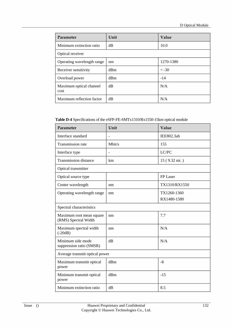
D Optical Module
Issue () Huawei Proprietary and Confidential
Copyright © Huawei Technologies Co., Ltd.
132
Parameter Unit Value
Minimum extinction ratio dB 10.0
Optical receiver
Operating wavelength range nm 1270-1380
Receiver sensitivity dBm < -30
Overload power dBm -14
Maximum optical channel
cost
dB N/A
Maximum reflection factor dB N/A
Table D-4 Specifications of the eSFP-FE-SMTx1310/Rx1550-15km optical module
Parameter Unit Value
Interface standard - IEE802.3ah
Transmission rate Mbit/s 155
Interface type - LC/PC
Transmission distance km 15 ( 9.32 mi. )
Optical transmitter
Optical source type FP Laser
Center wavelength nm TX1310/RX1550
Operating wavelength range nm TX1260-1360
RX1480-1580
Spectral characteristics
Maximum root mean square
(RMS) Spectral Width
nm 7.7
Maximum spectral width
(-20dB)
nm N/A
Minimum side mode
suppression ratio (SMSR)
dB N/A
Average transmit optical power
Maximum transmit optical
power
dBm -8
Minimum transmit optical
power
dBm -15
Minimum extinction ratio dB 8.5

D Optical Module
Issue () Huawei Proprietary and Confidential
Copyright © Huawei Technologies Co., Ltd.
133
Parameter Unit Value
Optical receiver
Operating wavelength range nm 1480-1580
Receiver sensitivity dBm -32
Overload power dBm -8
Maximum optical channel
cost dB N/A
Maximum reflection factor dB N/A
Table D-5 Specifications of the eSFP-STM1-SM1310-40K optical module
Parameter Unit Value
Interface standard - STM-1 L-1.1, OC-3
Transmission rate Mbit/s 155.52
Interface type - LC
Transmission distance km 40 ( 24.86 mi. )
Optical transmitter
Optical source type FP Laser
Center wavelength nm 1310
Operating wavelength range nm 1263-1360
Spectral characteristics
Maximum root mean square
(RMS) Spectral Width
nm 4
Maximum spectral width
(-20dB)
nm 1
Minimum side mode
suppression ratio (SMSR) dB 30
Average transmit optical power
Maximum transmit optical
power
dBm 0
Minimum transmit optical
power
dBm -5
Minimum extinction ratio dB 10
Optical receiver
Operating wavelength range nm 1260-1580

D Optical Module
Issue () Huawei Proprietary and Confidential
Copyright © Huawei Technologies Co., Ltd.
134
Parameter Unit Value
Receiver sensitivity dBm < -37
Overload power dBm -10
Maximum optical channel
cost
dB N/A
Maximum reflection factor dB N/A
Table D-6 Specifications of the eSFP-STM1-SM1550-80K optical module
Parameter Unit Value
Interface standard - STM-1 L-1.2, OC-3
Transmission rate Mbit/s 155.52
Interface type - LC
Transmission distance km 80 ( 49.71 mi. )
Optical transmitter
Optical source type DFB-LD
Center wavelength nm 1550
Operating wavelength range nm 1500-1580
Spectral characteristics
Maximum root mean square
(RMS) Spectral Width
nm N/A
Maximum spectral width
(-20dB)
nm 1.0
Minimum side mode
suppression ratio (SMSR)
dB 30
Average transmit optical power
Maximum transmit optical
power
dBm 0
Minimum transmit optical
power
dBm -5
Minimum extinction ratio dB 10
Optical receiver
Operating wavelength range nm 1260-1580
Receiver sensitivity dBm < -37
Overload power dBm -10

D Optical Module
Issue () Huawei Proprietary and Confidential
Copyright © Huawei Technologies Co., Ltd.
135
Parameter Unit Value
Maximum optical channel
cost
dB N/A
Maximum reflection factor dB N/A
D.3 1 Gbit/s Electrical Transceiver
The 1 Gbit/s electrical transceiver can be applied to the GE electrical interfaces.
Table D-7 lists the currently available 1 Gbit/s electrical transceivers.
Table D-7 1 Gbit/s electrical transceivers
Product Model
BOM Number
Interface Standard
Transmission Distance
Mode Auto-negotiation
Remarks
SFP/RJ45-
GE-100m
34100080 1000BAS
E-T
100 m
( 328.08
ft )
RJ-45 Supported -
Table D-8 Basic features of 1 Gbit/s electrical transceivers and the compliant standards
Item Description Remarks
Interface standard IEEE Std 802.3z, IEEE Std
802.3ab
GBIC R5.5(34100044)
SFP MSA(34100052,
34100080)
-
Temperature 0-75°C ( 32°F - 167°F) -
Digital diagnosis N/A -
Environment standard RoHS(exempted) -
Security standard FCC class B, IEC 61000-4-3 -
ESD >500V Human body model
Table D-9 Specifications of 1 Gbit/s Electrical Transceivers
Parameter Unit Value Remarks
Interface standard - 1000BASE-T -
Transmission rate Mbit/s 10-1000 Complying with

D Optical Module
Issue () Huawei Proprietary and Confidential
Copyright © Huawei Technologies Co., Ltd.
136
Parameter Unit Value Remarks
IEEE802.3
Interface type - RJ-45
Transmission
distance
m 100 ( 328.08 ft ) Category 5 UTP,
BER < 10-10
,
(GBIC/RJ45-GE-10
0)
Category 5 UTP,
BER < 10-12
,
(SFP/RJ45-GE-100)
D.4 1.25 Gbit/s SFP/eSFP Optical Module
The 1.25 Gbit/s SFP/eSFP optical modules of different levels can be applied to the GE
interface . The wavelength of the common 1.25 Gbit/s SFP/eSFP optical modules can be 850
nm, 1310 nm, or 1550 nm and the transmission distance ranges from 0.5 km (0.31 mi) to 100
km (62.14 mi). The wavelength of the 1.25 Gbit/s SFP/eSFP CWDM optical module ranges
from 1470 nm to 1610 nm and the transmission distance is 70 km (43.50 mi).
Table D-10 lists the currently available 1.25 Gbit/s SFP/eSFP optical modules.
Table D-10 1.25 Gbit/s SFP/eSFP optical modules
Product Model
BOM Number
Interface Standard
Transmission Distance (km)(mi)
Mode Wavelength (nm)
Remarks
eSFP-GE-
MM850-5
00m
34060286 1000BAS
E-SX
0.5(0.31) Multimod
e
850 Preferred
eSFP-GE-
SM1310-1
0Km
34060473 1000BAS
E-LX
10(6.21) Single-mo
de
1310 Preferred
eSFP-GE-
SM1310-4
0Km
34060298 1000BAS
E-LX
40(24.86) Single-mo
de
1310 Preferred
eSFP-GE-
SM1550-8
0Km
34060360 1000BAS
E-ZX
80(49.71) Single-mo
de
1550 Preferred
eSFP-GE-
SM1550-1
00Km
34060295 1000BAS
E-ZX
100(62.14
)
Single-mo
de
1550 -

D Optical Module
Issue () Huawei Proprietary and Confidential
Copyright © Huawei Technologies Co., Ltd.
137
Table D-11 List of 1.25 Gbit/s SFP/eSFP CWDM optical modules
Product Model
BOM Number
Interface Standard
Transmission Distance (km)(mi)
Mode Wavelength (nm)
Remarks
eSFP-100
M~2.67G
bps-SM14
71-80Km
34060483 CWDM 80(50) Single-mo
de
1471 -
eSFP-100
M~2.67G
bps-SM14
91-80Km
34060481 CWDM 80(50) Single-mo
de
1491 -
eSFP-100
M~2.67G
bps-SM15
11-80Km
34060479 CWDM 80(50) Single-mo
de
1511 -
eSFP-100
M~2.67G
bps-SM15
31-80Km
34060482 CWDM 80(50) Single-mo
de
1531 -
eSFP-100
M~2.67G
bps-SM15
51-80Km
34060478 CWDM 80(50) Single-mo
de
1551 -
eSFP-100
M~2.67G
bps-SM15
71-80Km
34060476 CWDM V80(50) Single-mo
de
1571 -
eSFP-100
M~2.67G
bps-SM15
91-80Km
34060477 CWDM 80(50) Single-mo
de
1591 -
eSFP-100
M~2.67G
bps-SM16
11-80Km
34060380 CWDM 80(50) Single-mo
de
1611 -
Table D-12 Basic features of 1.25 Gbit/s SFP/eSFP optical modules and the compliant standards
Item Description Remarks
Interface standard IEEE802.3, SFP MSA -
Bit Error Ratio (BER) < 1 x 10E -12
-
Temperature 0°C -70°C (32°F -158°F) -

D Optical Module
Issue () Huawei Proprietary and Confidential
Copyright © Huawei Technologies Co., Ltd.
138
Item Description Remarks
Digital diagnosis SFF-8472(exclude SFP
optical modules)
-
Environment standard RoHS(exempted) -
Security standard FCC class B, IEC 60825-1
Class 1
-
ESD >500V Human body model
Table D-13 Specifications of the eSFP-GE-MM850-500 optical module
Parameter Unit Value
Interface standard - 1000BASE-SX
Transmission rate Mbit/s 1.25 G
Interface type - LC
Transmission distance m(ft.) 500(310.7) (50/125 um
MMF)
m(ft.) 200(124.28) (62.5/125 um
MMF)
Optical transmitter
Optical source type VCSEL
Center wavelength nm 850
Operating wavelength range nm 830-860
Spectral characteristics
Maximum root mean square
(RMS) Spectral Width
nm 0.85
Maximum spectral width
(-20dB)
nm N/A
Minimum side mode
suppression ratio (SMSR)
dB N/A
Average transmit optical power
Maximum transmit optical
power dBm -3
Minimum transmit optical
power
dBm -9
Minimum extinction ratio dB 9.0
Optical receiver
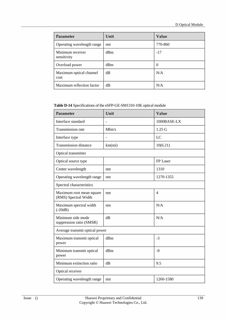
D Optical Module
Issue () Huawei Proprietary and Confidential
Copyright © Huawei Technologies Co., Ltd.
139
Parameter Unit Value
Operating wavelength range nm 770-860
Minimum receiver
sensitivity
dBm -17
Overload power dBm 0
Maximum optical channel
cost
dB N/A
Maximum reflection factor dB N/A
Table D-14 Specifications of the eSFP-GE-SM1310-10K optical module
Parameter Unit Value
Interface standard - 1000BASE-LX
Transmission rate Mbit/s 1.25 G
Interface type - LC
Transmission distance km(mi) 10(6.21)
Optical transmitter
Optical source type FP Laser
Center wavelength nm 1310
Operating wavelength range nm 1270-1355
Spectral characteristics
Maximum root mean square
(RMS) Spectral Width
nm 4
Maximum spectral width
(-20dB)
nm N/A
Minimum side mode
suppression ratio (SMSR)
dB N/A
Average transmit optical power
Maximum transmit optical
power
dBm -3
Minimum transmit optical
power
dBm -9
Minimum extinction ratio dB 9.5
Optical receiver
Operating wavelength range nm 1260-1580
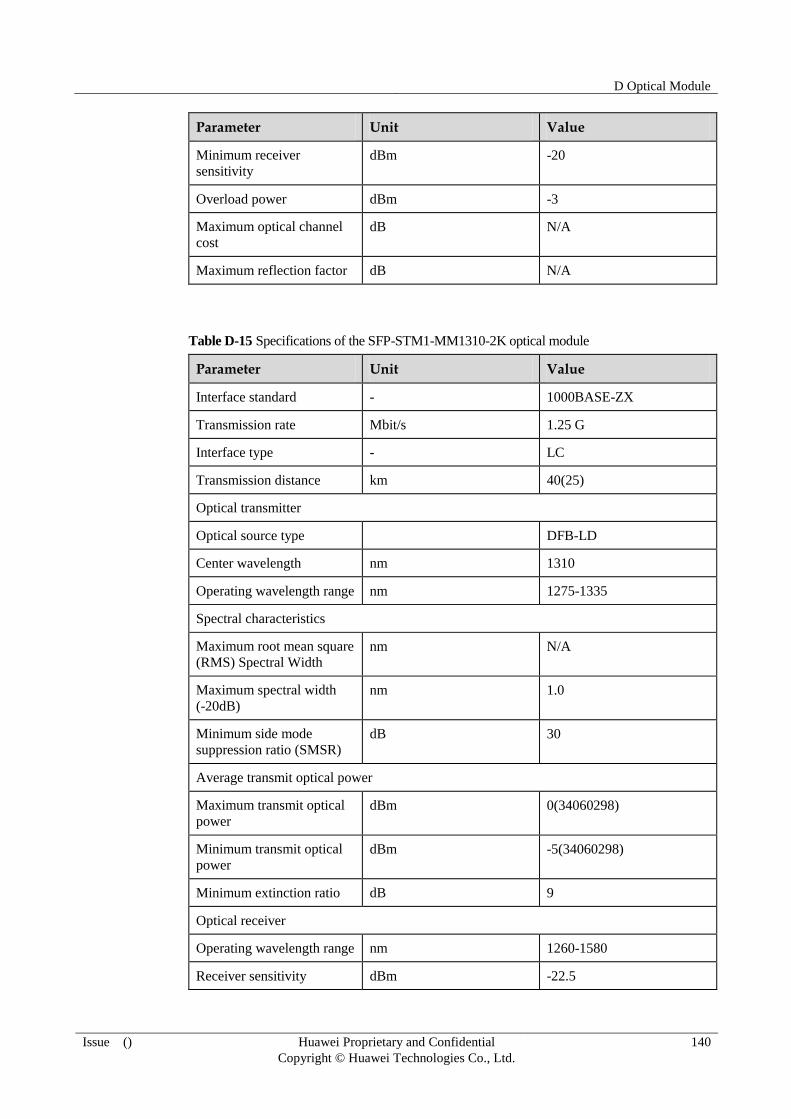
D Optical Module
Issue () Huawei Proprietary and Confidential
Copyright © Huawei Technologies Co., Ltd.
140
Parameter Unit Value
Minimum receiver
sensitivity
dBm -20
Overload power dBm -3
Maximum optical channel
cost
dB N/A
Maximum reflection factor dB N/A
Table D-15 Specifications of the SFP-STM1-MM1310-2K optical module
Parameter Unit Value
Interface standard - 1000BASE-ZX
Transmission rate Mbit/s 1.25 G
Interface type - LC
Transmission distance km 40(25)
Optical transmitter
Optical source type DFB-LD
Center wavelength nm 1310
Operating wavelength range nm 1275-1335
Spectral characteristics
Maximum root mean square
(RMS) Spectral Width
nm N/A
Maximum spectral width
(-20dB)
nm 1.0
Minimum side mode
suppression ratio (SMSR)
dB 30
Average transmit optical power
Maximum transmit optical
power
dBm 0(34060298)
Minimum transmit optical
power
dBm -5(34060298)
Minimum extinction ratio dB 9
Optical receiver
Operating wavelength range nm 1260-1580
Receiver sensitivity dBm -22.5

D Optical Module
Issue () Huawei Proprietary and Confidential
Copyright © Huawei Technologies Co., Ltd.
141
Parameter Unit Value
Overload power dBm -3
Maximum optical channel
cost
dB N/A
Maximum reflection factor dB N/A
Table D-16 Specifications of the eSFP-GE-SM1550-80K optical module
Parameter Unit Value
Interface standard - 1000BASE-ZX
Transmission rate Mbit/s 1.25 G
Interface type - LC
Transmission distance km(mi) 80(50)
Optical transmitter
Optical source type DFB-LD
Center wavelength nm 1550
Operating wavelength range nm 1540-1570
Spectral characteristics
Maximum root mean square
(RMS) Spectral Width
nm N/A
Maximum spectral width
(-20dB)
nm 1.0
Minimum side mode
suppression ratio (SMSR)
dB 30
Average transmit optical power
Maximum transmit optical
power
dBm 3
Minimum transmit optical
power
dBm -2
Minimum extinction ratio dB 9
Optical receiver
Operating wavelength range nm 1270-1570
Minimum receiver
sensitivity dBm -22
Overload power dBm -3

D Optical Module
Issue () Huawei Proprietary and Confidential
Copyright © Huawei Technologies Co., Ltd.
142
Parameter Unit Value
Maximum optical channel
cost
dB N/A
Maximum reflection factor dB N/A
Table D-17 Specifications of the eSFP-GE-SM1550-100K optical module
Parameter Unit Value
Interface standard - 1000BASE-ZX
Transmission rate Mbit/s 1.25 G
Interface type - LC
Transmission distance km(mi) 100(62)
Optical transmitter
Optical source type DFB-LD
Center wavelength nm 1550
Operating wavelength range nm 1540-1570
Spectral characteristics
Maximum root mean square
(RMS) Spectral Width
nm N/A
Maximum spectral width
(-20dB)
nm 1.0
Minimum side mode
suppression ratio (SMSR)
dB 30
Average transmit optical power
Maximum transmit optical
power
dBm 5
Minimum transmit optical
power
dBm 0
Minimum extinction ratio dB 9
Optical receiver
Operating wavelength range nm 1270-1600
Minimum receiver
sensitivity
dBm -30
Overload power dBm -10
Maximum optical channel dB N/A

D Optical Module
Issue () Huawei Proprietary and Confidential
Copyright © Huawei Technologies Co., Ltd.
143
Parameter Unit Value
cost
Maximum reflection factor dB N/A
Table D-18 Specifications of the 1.25 Gbit/s CWDM 80 km (50 mi) eSFP optical module
Parameter Unit Value
Interface standard - CWDM
Transmission rate Mbit/s 1.25 G
Interface type - LC
Transmission distance km(mi) 80(50)
Optical transmitter
Optical source type DFB-LD
Center wavelength nm 1471
(eSFP-100M~2.67Gbps-SM
1471-80Km)
1491
(eSFP-100M~2.67Gbps-SM
1491-80Km)
1511
(eSFP-100M~2.67Gbps-SM
1511-80Km)
1531
(eSFP-100M~2.67Gbps-SM
1531-80Km)
1551
(eSFP-100M~2.67Gbps-SM
1551-80Km)
1571
(eSFP-100M~2.67Gbps-SM
1571-80Km)
1591
(eSFP-100M~2.67Gbps-SM
1591-80Km)
1611
(eSFP-100M~2.67Gbps-SM
1611-80Km)
Operating wavelength range nm 1464.5-1477.5
(eSFP-100M~2.67Gbps-SM
1471-80Km)

D Optical Module
Issue () Huawei Proprietary and Confidential
Copyright © Huawei Technologies Co., Ltd.
144
Parameter Unit Value
1484.5-1497.5
(eSFP-100M~2.67Gbps-SM
1491-80Km)
1504.5-1517.5
(eSFP-100M~2.67Gbps-SM
1511-80Km)
1524.5-1537.5
(eSFP-100M~2.67Gbps-SM
1531-80Km)
1544.5-1557.5
(eSFP-100M~2.67Gbps-SM
1551-80Km)
1564.5-1577.5
(eSFP-100M~2.67Gbps-SM
1571-80Km)
1584.5-1597.5
(eSFP-100M~2.67Gbps-SM
1591-80Km)
1604.5-1617.5
(eSFP-100M~2.67Gbps-SM
1611-80Km)
Spectral characteristics
Maximum root mean square
(RMS) Spectral Width
nm N/A
Maximum spectral width
(-20dB)
nm 1.0
Minimum side mode
suppression ratio (SMSR)
dB 30
Average transmit optical power
Maximum transmit optical
power
dBm 5
Minimum transmit optical
power
dBm 0
Minimum extinction ratio dB 8.2
Optical receiver
Operating wavelength range nm 1270-1620
Minimum receiver
sensitivity
dBm -28
Overload power dBm -9
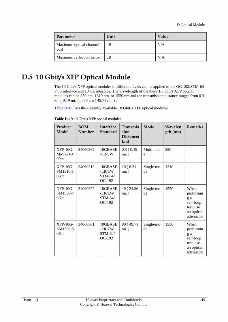
D Optical Module
Issue () Huawei Proprietary and Confidential
Copyright © Huawei Technologies Co., Ltd.
145
Parameter Unit Value
Maximum optical channel
cost
dB N/A
Maximum reflection factor dB N/A
D.5 10 Gbit/s XFP Optical Module
The 10 Gbit/s XFP optical modules of different levels can be applied to the OC-192/STM-64
POS interface and 10 GE interface. The wavelength of the these 10 Gbit/s XFP optical
modules can be 850 nm, 1310 nm, or 1550 nm and the transmission distance ranges from 0.3
km ( 0.19 mi. ) to 80 km ( 49.71 mi. ) .
Table D-19 lists the currently available 10 Gbit/s XFP optical modules.
Table D-19 10 Gbit/s XFP optical modules
Product Model
BOM Number
Interface Standard
Transmission Distance(km)
Mode Wavelength (nm)
Remarks
XFP-10G-
MM850-3
00m
34060362 10GBASE
-SR/SW
0.3 ( 0.19
mi. )
Multimod
e
850 -
XFP-10G-
SM1310-1
0Km
34060313 10GBASE
-LR/LW
STM-64/
OC-192
10 ( 6.21
mi. )
Single-mo
de
1310 -
XFP-10G-
SM1550-4
0Km
34060322 10GBASE
-ER/EW
STM-64/
OC-192
40 ( 24.86
mi. )
Single-mo
de 1550 When
performin
g a
self-loop
test, use
an optical
attenuator
XFP-10G-
SM1550-8
0Km
34060361 10GBASE
-ZR/ZW
STM-64/
OC-192
80 ( 49.71
mi. )
Single-mo
de
1550 When
performin
g a
self-loop
test, use
an optical
attenuator
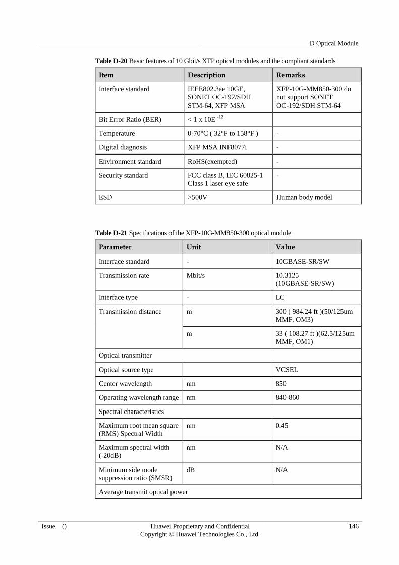
D Optical Module
Issue () Huawei Proprietary and Confidential
Copyright © Huawei Technologies Co., Ltd.
146
Table D-20 Basic features of 10 Gbit/s XFP optical modules and the compliant standards
Item Description Remarks
Interface standard IEEE802.3ae 10GE,
SONET OC-192/SDH
STM-64, XFP MSA
XFP-10G-MM850-300 do
not support SONET
OC-192/SDH STM-64
Bit Error Ratio (BER) < 1 x 10E -12
Temperature 0-70°C ( 32°F to 158°F ) -
Digital diagnosis XFP MSA INF8077i -
Environment standard RoHS(exempted) -
Security standard FCC class B, IEC 60825-1
Class 1 laser eye safe
-
ESD >500V Human body model
Table D-21 Specifications of the XFP-10G-MM850-300 optical module
Parameter Unit Value
Interface standard - 10GBASE-SR/SW
Transmission rate Mbit/s 10.3125
(10GBASE-SR/SW)
Interface type - LC
Transmission distance m 300 ( 984.24 ft )(50/125um
MMF, OM3)
m 33 ( 108.27 ft )(62.5/125um
MMF, OM1)
Optical transmitter
Optical source type VCSEL
Center wavelength nm 850
Operating wavelength range nm 840-860
Spectral characteristics
Maximum root mean square
(RMS) Spectral Width
nm 0.45
Maximum spectral width
(-20dB)
nm N/A
Minimum side mode
suppression ratio (SMSR)
dB N/A
Average transmit optical power

D Optical Module
Issue () Huawei Proprietary and Confidential
Copyright © Huawei Technologies Co., Ltd.
147
Parameter Unit Value
Maximum transmit optical
power
dBm -1.3
Minimum transmit optical
power
dBm -7.3
Minimum extinction ratio dB 3.0
Optical receiver
Operating wavelength range nm 840-860
Receiver sensitivity dBm < -7.5
Overload power dBm -1
Maximum optical channel
cost
dB N/A
Maximum reflection factor dB -12
Table D-22 Specifications of the XFP-10G-SM1310-10K optical module
Parameter Unit Value
Interface standard - 10GBASE-LR/LW,
STM-64/OC-192
Transmission rate Gbit/s 9.95328 (STM-64/OC-192)
10.3125
(10GBASE-LR/LW)
Interface type - LC
Transmission distance km 10 ( 6.21 mi. )
Optical transmitter
Optical source type DFB-LD
Center wavelength nm 1310
Operating wavelength range nm 1290-1330
Spectral characteristics
Maximum root mean square
(RMS) Spectral Width
nm N/A
Maximum spectral width
(-20dB)
nm 1.0
Minimum side mode
suppression ratio (SMSR)
dB 30
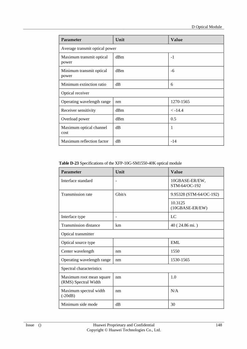
D Optical Module
Issue () Huawei Proprietary and Confidential
Copyright © Huawei Technologies Co., Ltd.
148
Parameter Unit Value
Average transmit optical power
Maximum transmit optical
power
dBm -1
Minimum transmit optical
power
dBm -6
Minimum extinction ratio dB 6
Optical receiver
Operating wavelength range nm 1270-1565
Receiver sensitivity dBm < -14.4
Overload power dBm 0.5
Maximum optical channel
cost
dB 1
Maximum reflection factor dB -14
Table D-23 Specifications of the XFP-10G-SM1550-40K optical module
Parameter Unit Value
Interface standard - 10GBASE-ER/EW,
STM-64/OC-192
Transmission rate Gbit/s 9.95328 (STM-64/OC-192)
10.3125
(10GBASE-ER/EW)
Interface type - LC
Transmission distance km 40 ( 24.86 mi. )
Optical transmitter
Optical source type EML
Center wavelength nm 1550
Operating wavelength range nm 1530-1565
Spectral characteristics
Maximum root mean square
(RMS) Spectral Width
nm 1.0
Maximum spectral width
(-20dB) nm N/A
Minimum side mode dB 30

D Optical Module
Issue () Huawei Proprietary and Confidential
Copyright © Huawei Technologies Co., Ltd.
149
Parameter Unit Value
suppression ratio (SMSR)
Average transmit optical power
Maximum transmit optical
power
dBm 2
Minimum transmit optical
power
dBm -1
Minimum extinction ratio dB 8.2
Optical receiver
Operating wavelength range nm 1270-1565
Receiver sensitivity dBm < -15
Overload power dBm -1
Maximum optical channel
cost
dB 2
Maximum reflection factor dB -26
Table D-24 Specifications of the XFP-10G-SM1550-80K optical module
Parameter Unit Value
Interface standard - 10GBASE-ER/EW,
STM-64/OC-192
Transmission rate Gbit/s 9.95328 (STM-64/OC-192)
10.3125
(10GBASE-ZR/ZW)
Interface type - LC
Transmission distance km 80 ( 49.71 mi. )
Optical transmitter
Optical source type EML
Center wavelength nm 1550
Operating wavelength range nm 1530-1565
Spectral characteristics
Maximum root mean square
(RMS) Spectral Width
nm 1.0
Maximum spectral width
(-20dB)
nm N/A

D Optical Module
Issue () Huawei Proprietary and Confidential
Copyright © Huawei Technologies Co., Ltd.
150
Parameter Unit Value
Minimum side mode
suppression ratio (SMSR)
dB 30
Average transmit optical power
Maximum transmit optical
power
dBm 4
Minimum transmit optical
power
dBm 0
Minimum extinction ratio dB 9
Optical receiver
Operating wavelength range nm 1270-1600
Receiver sensitivity dBm < -24
Overload power dBm -7
Maximum optical channel
cost
dB 2
Maximum reflection factor dB -27
E Glossary
Issue () Huawei Proprietary and Confidential
Copyright © Huawei Technologies Co., Ltd.
151
E Glossary
A
Asynchronizatio
n
Asynchronization does not use the exact data signals timed by the
clock. The signals have different frequencies and phases. The
asynchronizatioin usually encapsulates the bits into the control flag,
which specifies the beginning and end of the bits.
D
DCE Data Circuit-terminating Equipment is a network device composing the
UNI. DCE provides the physical connection to the network, forwards
the data, and provides the clock signals for the DTE.
DRAM Dynamic Random Access Memory. The information stored in the RAM
must be refreshed periodically. When the contents of the DRAM are
being refreshed, a user cannot access it. Delay can thus occur.
DTE Data terminal equipment is a user device composing the UNI. The DTE
accesses the data network through the DCE equipment (for example,
model) and usually uses the clock signals produced by DCE.
E
EMC Electro magnetic compatibility is the condition which prevails when
telecommunications equipment is performing its individually designed
function in a common electromagnetic environment without causing or
suffering unacceptable degradation due to unintentional
electromagnetic interference to or from other equipment in the same
environment.
F
Flash Flash is a kind of special Erasable Programmable Read Only Memory
(EEPROM), which can be completely erased and rewritten one time
instead of only one byte.

E Glossary
Issue () Huawei Proprietary and Confidential
Copyright © Huawei Technologies Co., Ltd.
152
N
NVRAM Nonvolatile Random Access Memory. The data in NVRAM cannot be
lost when the system is Down.
R
RAM Random Access Memory is a memory that can be lost easily, and read
and rewritten by the micro processor.
ROM Read Only Memory is a memory that cannot be lost easily, and can
only be read, but not written by the micro processor.
S
SRAM Static Random Access Memory is a type of random access memory. Its
contents can be saved only if the SRAM is provided with the
uninterrupted power supply. Unlike the DRAM, the SRAM does not
need to be refreshed repeatedly.
F Acronyms and Abbreviations
Issue () Huawei Proprietary and Confidential
Copyright © Huawei Technologies Co., Ltd.
153
F Acronyms and Abbreviations
A
AC Alternating Current
ATM Asynchronous Transfer Mode
AUX Auxiliary (port)
C
CAN Control Area Network
CE1 Channelized E1
CF Compact Flash
CLK Clock Card
CPU Central Processing Unit
CT1 Channelized T1
CTS Clear to Send
D
DC Direct Current
DCE Data Circuit-terminating Equipment
DSR Data Set Ready
DTE Data Terminal Equipments
DTR Data Terminal Ready
E
EMC Electro Magnetic Compatibility

F Acronyms and Abbreviations
Issue () Huawei Proprietary and Confidential
Copyright © Huawei Technologies Co., Ltd.
154
F
FAD Fabric Adaptor
FC Patch Cord (Connector + Fiber)
FCB Fan Control Board
FPIC Flexible Plug-in Card
G
GND Ground
I
IEC International Electrotechnical Commission
L
LC Lucent Connector
LPU Line Processing Unit
M
MPU Main Processing Unit
N
NEG Negative
NPU Network Processing Unit
NVRAM Non-Volatile Random Access Memory
O
ODF Optical Distribution Frame
OFL Offline
P
PC Personal Computer
PCB Printed Circuit Board
PCS Physical Coding Sublayer
PGND Protection Ground
F Acronyms and Abbreviations
Issue () Huawei Proprietary and Confidential
Copyright © Huawei Technologies Co., Ltd.
155
PMD Physical Medium Dependent
R
RJ45 Registered Jack 45
RTS Request to Send
RXD Receive Data
S
SC Square Connector
SDRAM Synchronous Dynamic Random Access
Memory
SFU Switch Fabric Unit
SMB Sub-miniature B
SRU Switch Router Unit
T
TXD Transmit Data
U
UART Universal Asynchronous
Receiver/Transmitter
UTP Unshielded Twisted Pair
V
VRP Versatile Routing Platform