huawei technologies co., ltd.€¦ · huawei technologies co., ltd. administration building, huawei...
TRANSCRIPT

Huawei Technologies Co., Ltd. Administration Building, Huawei Technologies Co., Ltd., Bantian, Longgang District, Shenzhen, P. R. China Postal Code: 518129 Website: http://www.huawei.com BOM: 31033171
Airbridge cBTS3612 CD
MA Base Station
On-site M
aintenance Manual
Airbridge cBTS3612 CD
MA Base Station
On-site M
aintenance Manual
Airbridge cBTS3612 CD
MA Base Station
On-site M
aintenance Manual
8.4cm
Huaw
ei Technologies Co., Ltd.
Huaw
ei Technologies Co., Ltd.
Huaw
ei Technologies Co., Ltd.
5.4cm
Airbridge cBTS3612 CDMA Base Station
On-site Maintenance Manual
On-site Maintenance Manual Airbridge cBTS3612 CDMA Base Station Table of Contents
i
Table of Contents
Chapter 1 Daily Maintenance ................................................... 1-1 1.1 Base Station Configuration ............................................ 1-1
1.2 Maintenance Instructions ............................................... 1-8
Chapter 2 General Fault Processing ........................................ 2-1 2.1 MS Access Network Failure ........................................... 2-1
2.1.1 Fault Description ................................................. 2-1
2.1.2 Troubleshooting .................................................. 2-1
2.2 Software Download Failure ............................................ 2-9
2.2.1 Fault Description ................................................. 2-9 2.2.2 Troubleshooting .................................................. 2-9
2.3 Base Station Initialization Failure.................................. 2-11
2.3.1 Fault Description ............................................... 2-11
2.3.2 Troubleshooting ................................................ 2-11
2.4 OML Failure................................................................ 2-13 2.4.1 Fault Description ............................................... 2-13
2.4.2 Troubleshooting ................................................ 2-13
2.5 Abis Signaling Link Failure ........................................... 2-17
2.5.1 Fault Description ............................................... 2-17
2.5.2 Troubleshooting ................................................ 2-17
Chapter 3 Component Failure Handling................................... 3-1
3.1 Component Failure Description ...................................... 3-1
3.1.1 Component Failure Detection ............................... 3-1 3.1.2 General Handling Procedure ................................ 3-1
3.2 Handling of Common Board Failure ................................ 3-5
On-site Maintenance Manual Airbridge cBTS3612 CDMA Base Station Table of Contents
ii
3.2.1 Fault Description ................................................. 3-5
3.2.2 Troubleshooting .................................................. 3-5
3.3 BTS Control Interface Module (BCIM)............................. 3-8
3.3.1 Fault Description ................................................. 3-8 3.3.2 Troubleshooting .................................................. 3-8
3.4 BTS Control & Clock Module (BCKM) ........................... 3-10
3.4.1 Fault Description ............................................... 3-10
3.4.2 Troubleshooting ................................................ 3-10
3.5 BTS Channel Process Module (BCPM)......................... 3-12 3.5.1 Fault Description ............................................... 3-12
3.5.2 Troubleshooting ................................................ 3-12
3.6 BTS Resource Distribution Module (BRDM).................. 3-14
3.6.1 Fault Description ............................................... 3-14
3.6.2 Troubleshooting ................................................ 3-14 3.7 BTS Transceiver Module (BTRM) ................................. 3-16
3.7.1 Fault Description ............................................... 3-16
3.7.2 Troubleshooting ................................................ 3-17
3.8 BTS High Power Amplifier Unit (BHPA) ........................ 3-20
3.8.1 Fault Description ............................................... 3-20 3.8.2 Troubleshooting ................................................ 3-20
3.9 Receive LNA Distribution Unit (RLDU).......................... 3-23
3.9.1 Fault Description ............................................... 3-23
3.9.2 Troubleshooting ................................................ 3-23
3.10 Power Supply Unit (PSU) ........................................... 3-25 3.10.1 Fault Description ............................................. 3-25
3.10.2 Troubleshooting............................................... 3-25
3.11 The RF Antenna and Feeder ...................................... 3-27
3.11.1 Fault Description ............................................. 3-27
3.11.2 Troubleshooting............................................... 3-27
On-site Maintenance Manual Airbridge cBTS3612 CDMA Base Station Table of Contents
iii
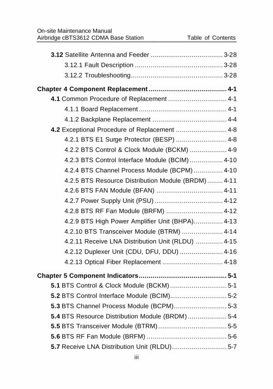
3.12 Satellite Antenna and Feeder ..................................... 3-28
3.12.1 Fault Description ............................................. 3-28
3.12.2 Troubleshooting............................................... 3-28
Chapter 4 Component Replacement ........................................ 4-1 4.1 Common Procedure of Replacement .............................. 4-1
4.1.1 Board Replacement ............................................. 4-1
4.1.2 Backplane Replacement ...................................... 4-4
4.2 Exceptional Procedure of Replacement .......................... 4-8 4.2.1 BTS E1 Surge Protector (BESP) .......................... 4-8
4.2.2 BTS Control & Clock Module (BCKM) ................... 4-9
4.2.3 BTS Control Interface Module (BCIM) ................. 4-10
4.2.4 BTS Channel Process Module (BCPM) ............... 4-10
4.2.5 BTS Resource Distribution Module (BRDM) ........ 4-11 4.2.6 BTS FAN Module (BFAN) .................................. 4-11
4.2.7 Power Supply Unit (PSU) ................................... 4-12
4.2.8 BTS RF Fan Module (BRFM) ............................. 4-12
4.2.9 BTS High Power Amplifier Unit (BHPA)............... 4-13
4.2.10 BTS Transceiver Module (BTRM) ..................... 4-14 4.2.11 Receive LNA Distribution Unit (RLDU) .............. 4-15
4.2.12 Duplexer Unit (CDU, DFU, DDU) ...................... 4-16
4.2.13 Optical Fiber Replacement ............................... 4-18
Chapter 5 Component Indicators............................................. 5-1 5.1 BTS Control & Clock Module (BCKM) ............................. 5-1
5.2 BTS Control Interface Module (BCIM)............................. 5-2
5.3 BTS Channel Process Module (BCPM)........................... 5-3
5.4 BTS Resource Distribution Module (BRDM) .................... 5-4 5.5 BTS Transceiver Module (BTRM) ................................... 5-5
5.6 BTS RF Fan Module (BRFM) ......................................... 5-6
5.7 Receive LNA Distribution Unit (RLDU)............................ 5-7
On-site Maintenance Manual Airbridge cBTS3612 CDMA Base Station Table of Contents
iv
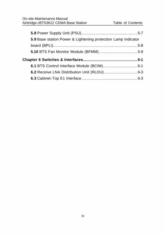
5.8 Power Supply Unit (PSU)............................................... 5-7
5.9 Base station Power & Lightening protection Lamp Indicator board (BPLI)....................................................................... 5-8
5.10 BTS Fan Monitor Module (BFMM) ................................ 5-9
Chapter 6 Switches & Interfaces.............................................. 6-1
6.1 BTS Control Interface Module (BCIM)............................. 6-1
6.2 Receive LNA Distribution Unit (RLDU)............................ 6-3
6.3 Cabinet-Top E1 Interface............................................... 6-3
On-site Maintenance Manual Airbridge cBTS3612 CDMA Base Station Chapter 1 Daily Maintenance
1-1
Chapter 1 Daily Maintenance
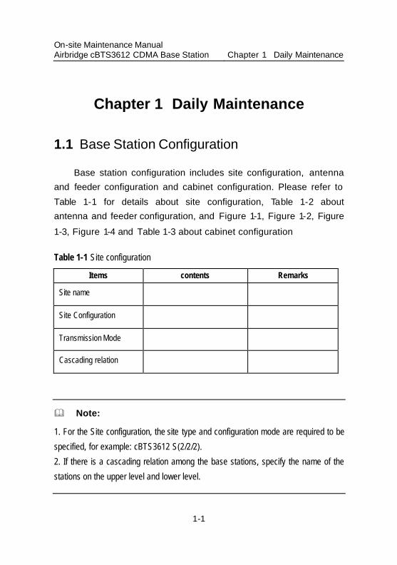
1.1 Base Station Configuration
Base station configuration includes site configuration, antenna and feeder configuration and cabinet configuration. Please refer to Table 1-1 for details about site configuration, Table 1-2 about antenna and feeder configuration, and Figure 1-1, Figure 1-2, Figure 1-3, Figure 1-4 and Table 1-3 about cabinet configuration
Table 1-1 Site configuration
Items contents Remarks
Site name
Site Configuration
Transmission Mode
Cascading relation
& Note:
1. For the Site configuration, the site type and configuration mode are required to be
specified, for example: cBTS3612 S(2/2/2).
2. If there is a cascading relation among the base stations, specify the name of the
stations on the upper level and lower level.
On-site Maintenance Manual Airbridge cBTS3612 CDMA Base Station Chapter 1 Daily Maintenance
1-2
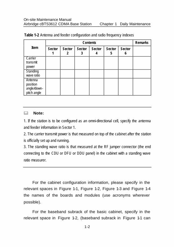
Table 1-2 Antenna and feeder configuration and radio frequency indexes
Contents Remarks Item Sector
1 Sector
2 Sector
3 Sector
4 Sector
5 Sector
6
Carrier transmit power
Standing wave ratio
Antenna position angle/down-pitch angle
& Note:
1. If the station is to be configured as an omni-directional cell, specify the antenna
and feeder information in Sector 1.
2. The carrier transmit power is that measured on top of the cabinet after the station
is officially set up and running. 3. The standing wave ratio is that measured at the RF jumper connector (the end
connecting to the CDU or DFU or DDU panel) in the cabinet with a standing wave
ratio measurer.
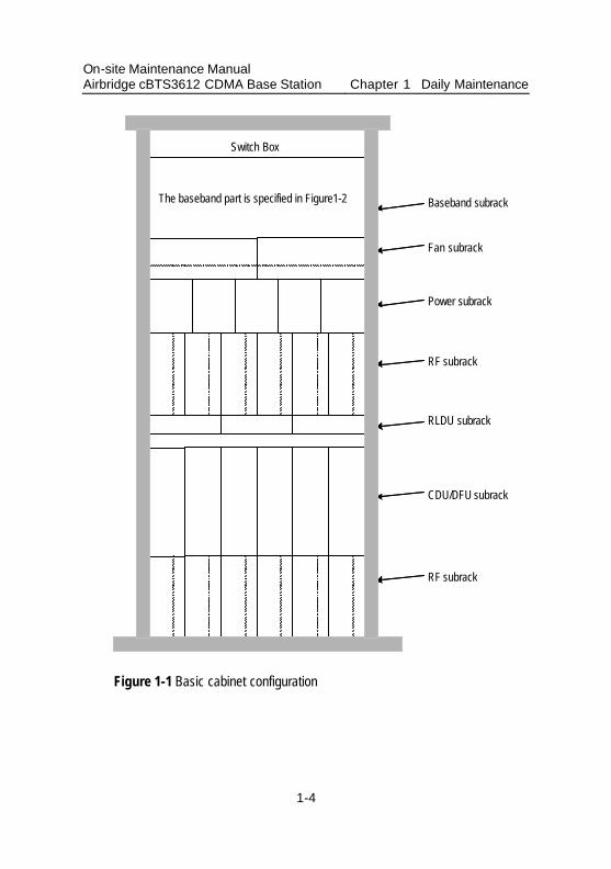
For the cabinet configuration information, please specify in the relevant spaces in Figure 1-1, Figure 1-2, Figure 1-3 and Figure 1-4 the names of the boards and modules (use acronyms wherever possible).
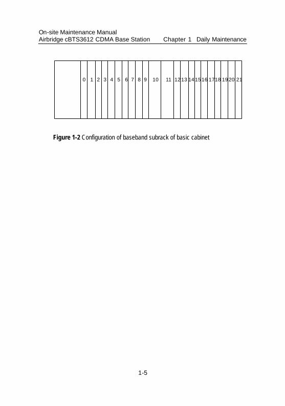
For the baseband subrack of the basic cabinet, specify in the relevant space in Figure 1-2, (baseband subrack in Figure 1-1 can

On-site Maintenance Manual Airbridge cBTS3612 CDMA Base Station Chapter 1 Daily Maintenance
1-3
be left blank). Since the extension cabinet has no baseband subrack, it can be ignored.
Additionally, Table 1-3 also needs to be completed, which is to make supplemental description of some of the boards or modules, switch box can be ignored.
On-site Maintenance Manual Airbridge cBTS3612 CDMA Base Station Chapter 1 Daily Maintenance
1-4
CDU/DFU subrack
RF subrack
RLDU subrack
Baseband subrack
RF subrack
basebandpart is specified in Figure 2
Power subrack
Fan subrack
Switch Box
The baseband part is specified in Figure1-2
Figure 1-1 Basic cabinet configuration
On-site Maintenance Manual Airbridge cBTS3612 CDMA Base Station Chapter 1 Daily Maintenance
1-5
0 1 2 3 4 5 6 7 8 10 11 12 13 14 15 16 1718 19 20 219
Figure 1-2 Configuration of baseband subrack of basic cabinet
On-site Maintenance Manual Airbridge cBTS3612 CDMA Base Station Chapter 1 Daily Maintenance
1-6
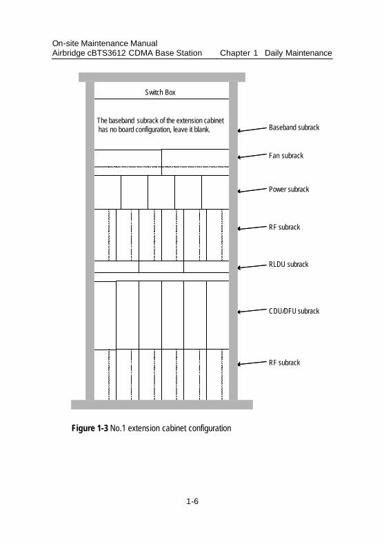
CDU/DFU subrack
RF subrack
RLDU subrack
Baseband subrack
RF subrack
basebandpart is specified in Figure 2
Power subrack
Fan subrack
Switch Box
The baseband subrack of the extension cabinethas no board configuration, leave it blank.
Figure 1-3 No.1 extension cabinet configuration
On-site Maintenance Manual Airbridge cBTS3612 CDMA Base Station Chapter 1 Daily Maintenance
1-7
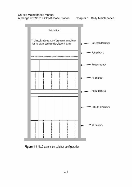
CDU/DFU subrack
RF subrack
RLDU subrack
Baseband subrack
RF subrack
basebandpart is specified in Figure 2
Power subrack
Fan subrack
Switch Box
Thebaseband subrack of the extension cabinethas no board configuration, leave it blank.
Figure 1-4 No.2 extension cabinet configuration
On-site Maintenance Manual Airbridge cBTS3612 CDMA Base Station Chapter 1 Daily Maintenance
1-8
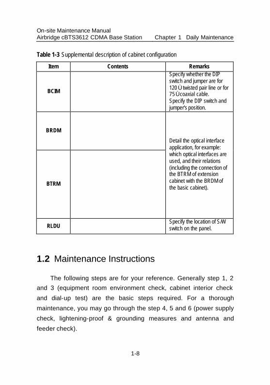
Table 1-3 Supplemental description of cabinet configuration
Item Contents Remarks
BCIM
Specify whether the DIP switch and jumper are for 120 Ù twisted pair line or for 75 Ù coaxial cable. Specify the DIP switch and jumper's position.
BRDM
BTRM
Detail the optical interface application, for example: which optical interfaces are used, and their relations (including the connection of the BTRM of extension cabinet with the BRDM of the basic cabinet).
RLDU
Specify the location of S/W switch on the panel.
1.2 Maintenance Instructions
The following steps are for your reference. Generally step 1, 2 and 3 (equipment room environment check, cabinet interior check and dial-up test) are the basic steps required. For a thorough maintenance, you may go through the step 4, 5 and 6 (power supply check, lightening-proof & grounding measures and antenna and feeder check).
On-site Maintenance Manual Airbridge cBTS3612 CDMA Base Station Chapter 1 Daily Maintenance
1-9
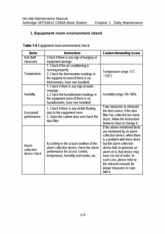
I. Equipment room environment check
Table 1-4 Equipment room environment check
Items Instructions Caution-demanding issues Anti-theft measures
Check if there is any sign of burglary or equipment damage
Temperature
1. Check if the air-conditioning is running properly. 2. Check the thermometer readings in the equipme nt room (if there is no thermometer, have one installed)
Temperature range: -5ÿC ~+50ÿC
Humidity
1. Check if there is any sign of water seepage. 2. C heck the humidiometer readings in the equipment room (if there is no humidiometer, have one installed)
Humidity range: 5%~90%.
Dust-proof performance
1. Check if there is any visible floating dust in the equipment room. 2. Open the cabinet door and check the dust filter
Take measures to eliminate the dust source, if the dust filter has collected too many dusts, follow the instructions below to clean or change it.
Alarm collection device check
According to the actual condition of the alarm collection device, check the alarm performance for access control, temperature, humidity and smoke, etc.
If the above-mentioned items are monitored by an alarm collection device, when there is a problem with these items but the alarm collection device fails to generate an alarm on it, that device may have run out of order. In such case, please refer to the relevant manuals for proper measures to cope with it.
On-site Maintenance Manual Airbridge cBTS3612 CDMA Base Station Chapter 1 Daily Maintenance
1-10
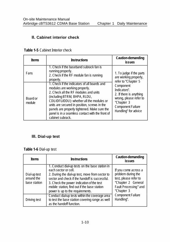
II. Cabinet interior check
Table 1-5 Cabinet Interior check
Items Instructions Caution-demanding issues
Fans
1. Check if the baseband subrack fan is running properly. 2. Check if the RF module fan is running properly.
Board or module
1. Check if the indicators of all boards and modules are working properly. 2. Check all the RF modules and units (including BTRM, BHPA, RLDU, CDU/DFU/DDU): whether all the modules or units are secured in position, screws in the panels are properly tightened. Make sure the panel is in a seamless contact with the front of cabinet subrack.
1. To judge if the parts are working properly, refer to "Chapter 5 Component Indicators". 2. If there is anything wrong, please refer to "Chapter 3 Component Failure Handling" for advice
III. Dial-up test
Table 1-6 Dial-up test
Items Instructions Caution-demanding issues
Dial-up test around the base station
1. Conduct dial-up tests on the base station in each sector or cell. 2. During the dial-up test, move from sector to sector and check if the handoff is successful. 3. Check the power indication of the test mobile station, find out if the base station power is up to the requirements.
Driving test Conduct dial-up tests within the coverage area to test the base station covering range as well as the handoff function.
If you come across a problem during the test, please refer to "Chapter 2 General Fault Processing" and "Chapter 3 Component Failure Handling".
On-site Maintenance Manual Airbridge cBTS3612 CDMA Base Station Chapter 1 Daily Maintenance
1-11
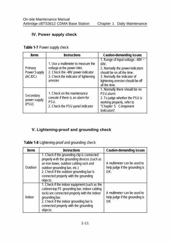
IV. Power supply check
Table 1-7 Power supply check
Items Instructions Caution-demanding issues
Primary Power Supply (AC/DC)
1. Use a multimeter to measure the voltage at the power inlet. 2. Check the -48V power indicator 3. Check the indicator of lightening arrester
1. Range of input voltage: -40V ~ 60V. 2. Normally the power indicators should be on all the time. 3. Normally the indicator of lightening arrester should be off all the time.
Secondary power supply (PSU)
1. Check on the maintenance console if there is an alarm for PSU. 2. Check the PSU panel indicator
1. Normally there should be no PSU alarm 2. To judge whether the PSU is working properly, refer to "Chapter 5 Component Indicators".
V. Lightening-proof and grounding check
Table 1-8 Lightening-proof and grounding check
Items Instructions Caution-demanding issues
Outdoor
1. Check if the grounding clip is connected properly w ith the grounding devices (such as an iron tower, outdoor cabling rack and outdoor grounding bar, etc.) 2. Check if the outdoor grounding bar is connected properly with the grounding objects.
A multimeter can be used to help judge if the grounding is OK.
Indoor
1. Check if the indoor equipment (such as the cabinet-top PE grounding bar, indoor cabling rack) are connected properly with the indoor grounding bar. 2. Check if the indoor grounding bar is connected properly with the grounding objects.
A multimeter can be used to help judge if the grounding is OK
On-site Maintenance Manual Airbridge cBTS3612 CDMA Base Station Chapter 1 Daily Maintenance
1-12
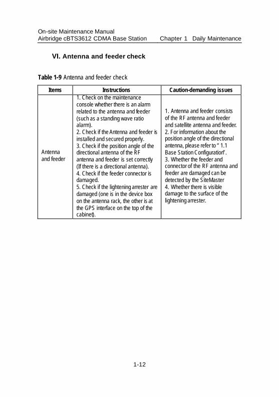
VI. Antenna and feeder check
Table 1-9 Antenna and feeder check
Items Instructions Caution-demanding issues
Antenna and feeder
1. Check on the maintenance console whether there is an alarm related to the antenna and feeder (such as a standing wave ratio alarm). 2. Check if the Antenna and feeder is installed and secured properly. 3. Check if the position angle of the directional antenna of the RF antenna and feeder is set correctly (If there is a directional antenna). 4. Check if the feeder connector is damaged. 5. Check if the lightening arrester are damaged (one is in the device box on the antenna rack, the other is at the GPS interface on the top of the cabinet).
1. Antenna and feeder consists of the RF antenna and feeder and satellite antenna and feeder. 2. For information about the position angle of the directional antenna, please refer to “1.1 Base Station Configuration”. 3. Whether the feeder and connector of the RF antenna and feeder are damaged can be detected by the SiteMaster 4. Whether there is visible damage to the surface of the lightening arrester.
On-site Maintenance Manual Airbridge cBTS3612 CDMA Base Station
Chapter 2 General Fault Processing
2-1
Chapter 2 General Fault Processing
2.1 MS Access Network Failure
When the MS is powered on, it will go through the following processes: system determination substate, pilot channel acquisition substate, sync channel acquisition substate, timing change substate and finally enter the mobile station idle state and receive the correct system message within the specific time. Only after going through all these processes, can the MS access the network and work properly.
2.1.1 Fault Description
The MS is unable to access the CDMA network after powered on.
2.1.2 Troubleshooting
First make sure the MS parameters (such as basic frequency, assistant frequency, and SID, NID etc.) have been correctly set, and then go through the following processes one by one to locate and eliminate problems.
I. Check if the BTS is running properly
As BTS is not running, the MS will not be able to connect to the network. The reasons that BTS is not running could be:
On-site Maintenance Manual Airbridge cBTS3612 CDMA Base Station
Chapter 2 General Fault Processing
2-2
1) The BTS equipment is in a faulty condition, which will result in the BTS start-up failure.
2) The BTS is not configured with correct parameters, which will also result in the BTS start-up failure.
Please refer to “2.3 Base Station Initialization Failure” for fault elimination measures.
II. Check if there is anything wrong with the Abis signaling link
Abis signaling link failure will also result in the MS network connection failure.
1) After the BTS start -up, if the Abis signaling link goes wrong, BSC will be unable to perform logic configuration on BTS, which will result in the MS network connection failure.
2) If the BTS has obtained the correct logic configuration, when the Abis signaling link goes wrong, the BTS will turn off the transmitting signal of the BTRM to which all its sector carrier frequencies correspond. This will result in the MS network connection failure.
Through querying the current alarms of the BTS on the OMC console or BTS local maintenance console, find out if there is an “Abis signaling link failure” alarm.
Please refer to “2.5 Abis Signaling Link Failure” for fault elimination measures.
On-site Maintenance Manual Airbridge cBTS3612 CDMA Base Station
Chapter 2 General Fault Processing
2-3
III. Check if the cell has obtained the BSC logical configuration
1) If the cell has not obtained the logic configuration, i.e. common channels for pilot frequency, synchronization, paging common channels, etc. has not been established or an overhead message update has not been performed, the MS will of course not be able to connect to the network.
Check the configuration progress report for this cell in the “BTS status” window on the OMC console: if there is no such progress reports as “Common channel established successfully” and “Overhead message updated successfully”, that means the logic configuration for this cell has not completed.
2) Sometimes the unavailability of certain physical equipment, or some operation mistakes (such as deleting a device by mistake) will result in the cell being deleted and the MS being unable to connect to the network.
Check the configuration progress report for this cell in the “BTS status” window on the OMC console: if there is a progress report saying “Cell deleted”, that means the cell has been deleted.
If the cell has not obtained the logic configuration, we need to verify the following items by checking the relevant indicators, board status and alarm messages, etc.:
l Whether the BTRM used in this cell is working properly; l Whether the BCPM used in this cell is working properly; l Whether the corresponding BRDM is working properly;
On-site Maintenance Manual Airbridge cBTS3612 CDMA Base Station
Chapter 2 General Fault Processing
2-4
l Whether the optical fiber of the BTRM and BRDM is connected properly;
l Whether the BCIM is working properly; l Whether the Abis signaling link is working properly; l Whether the BSC is working properly; l Whether the parameters in the BTS and BSC are in correct
corresponding relations.
If there is a problem detected in a certain step, refer to the relevant chapter for proper handling measures, for example, if there is problem with the BTRM, go to “3.7 BTS Transceiver Module (BTRM)” for proper measures.
IV. Cell is blocked
If we can see from the OMC console that the logic configuration for the cell has been completed, but the MS still can not connect to the network, we can then check whether this cell has been blocked.
When a cell is blocked, the BTS will turn off the transmitting signal of the BTRM, to which the carrier of this cell corresponds, which will result in the MS network connection failure.
We can use command “DSP BTSBRDSTAT” to query the BTRM status on the OMC console and find out if the BTRM to which this cell corresponds is blocked.
If the cell is blocked, the mobile station will not be able to connect to the network until the user unblock the cell.
On-site Maintenance Manual Airbridge cBTS3612 CDMA Base Station
Chapter 2 General Fault Processing
2-5
V. Check receiving channel
If we can see from the OMC console the logic configuration for the cell has been completed, but the MS still can not connect to the network, we can then check whether the receiving channel is working properly.
If the BTS receiving channel is not working properly, it will result in heavy bit errors. As a result, the MS will lose network connection frequently. When the MS switches on, it will send a switch-on registration message to the BTS. Due to the receiving channel failure, the BTS is unable to receive the registration message and thus will not send the response back to the MS, this will result in the MS registration failure. When the registration fails, the MS will enter the system confirmation substate and start recapturing the network, when the network is captured, the MS will again activate the switch-on registration… this will go on and the MS is still unable to connect to the network.
We can use the CDMA test MS to trace the air interface message: if the MS has sent the registration message and does not receive the BTS response, the BTS inverse receiving channel must be faulty.
If there is a problem with the receiving channel, we can go through the following steps as well as checking the relevant indicators, board status and alarm messages, etc. to locate it:
l Whether the CDU (or DFU, or DDU), RLDU and BTRM are secured in place, or whether the panel screws are all tightened;
l Whether the antenna and feeder is connected properly;
On-site Maintenance Manual Airbridge cBTS3612 CDMA Base Station
Chapter 2 General Fault Processing
2-6
l Whether the RLDU is power on and works properly; l Whether the RLDU panel configuration selection switch
“S/W” is in the correct position. Refer to “Table 6-2 Description of RLDU switches” for details about it;
l Whether the BTRM is working properly; l Whether the BCPM is working properly; l Whether the BTS physical configuration is correct,
including the parameters of the cell and inverse searching parameters, etc.
If there is a problem detected in a certain step, refer to the relevant chapter for proper handling measures, for example, if there is problem with the BTRM, go to “3.7 BTS Transceiver Module (BTRM)” for proper handling measures.
VI. Check transmitting channel
The BTRM, BHPA, CDU (or DFU, or DDU) and the antenna and feeder constitute the transmitting channel. The malfunctioning of transmitting channel will result in no BTS signal output or abnormal BTS signal output. In such case, we can still find on the OMC console that the logic configuration for the cell has been completed, but the MS will not be able to connect to the network. We can then go through the following steps as well as checking the relevant indicators, board status and alarm messages, etc. to locate the problem:
l Whether the CDU (or DFU, or DDU), BHPA and BTRM are secured in place, or whether the panel screws are all tightened;
On-site Maintenance Manual Airbridge cBTS3612 CDMA Base Station
Chapter 2 General Fault Processing
2-7
l Whether the transmission driving component of the BTRM is working properly;
l Whether the CDU (or DFU, DDU) is working properly. l Whether the connection between the BTRM and BHPA is
secure; l Whether the BHPA is working properly; l Whether the connection between the BHPA and CDU (or
DFU, DDU) is secure; l Whether the feeder connection from the CDU (or DFU,
DDU) to the top of the cabinet is secure; l Whether the feeder connection from the top of the cabinet
to the antenna is secure; l Whether the blind mate in each module of the transmitting
channel are secured in place. l Whether the antenna is installed correctly; l Whether there is a standing wave ratio alarm;
If there is a problem detected in a certain step, refer to the relevant chapter for proper handling measures, for example, if there is a problem with the BTRM, go to “3.7 BTS Transceiver Module (BTRM)” for proper handling measures.
VII. Check cell gain & common channel gain configuration
If we can see from the OMC console the logic configuration for the cell has been completed, but the MS still can not connect to the network, we can then check whether the gain parameters setting is correct when we configured the cell.
When configuring the cell, we need to configure the sector gain, carrier gain, pilot frequency signal gain, synchronization channel gain
On-site Maintenance Manual Airbridge cBTS3612 CDMA Base Station
Chapter 2 General Fault Processing
2-8
and paging channel gain, etc. If these parameters are not properly set (for example: they are set too low), the MS will not be able to capture the common channel and thus will not be able to connect to the network.
With the help of Abis-interface message tracing tool, find out whether the gain parameters carried in the Abis-Cell Setup message are correct, if not, reconfigure the BSC data configuration table.
VIII. Check overhead message
If we can see from the OMC console the logic configuration for the cell has been completed, but the MS still can not connect to the network, we can then check whether the overhead message is correct.
When the MS enters the idling status, it needs to receive all the overhead message set up by the system, which include at least the following five:
The synchronization message, access parameter message, system parameter message, CDMA channel list message, Neighbor List Message. Other overhead message may vary with the network parameter settings.
If any one of the above system messages is not received, the MS will not be able to connect to the network.
Additionally, the value setting in each of the parameters in the message will directly affect the MS network connection, therefore please be careful.
On-site Maintenance Manual Airbridge cBTS3612 CDMA Base Station
Chapter 2 General Fault Processing
2-9
With the help of the air interface signaling analyzer, it can be determined whether the MS has received all the system messages. Also, check whether the value setting in each of the parameters in the message is correct. If not, modify the BSC parameter configuration table and perform the overhead message update again.
2.2 Software Download Failure
2.2.1 Fault Description
Software download problems includes software download failure, maintenance console prompting failure or there being no correct prompt messages generated.
2.2.2 Troubleshooting
Software download failure may be caused by the following two factors: FTP client login failure and file loading abnormally terminated by the board.
I. FTP client login failure
1) First check if the BOOTP process of the OMU is running properly:
The OMU requests the BTS IP address via BOOTP. If this process fails, the BTS IP address will not be obtained, and of course it will not be able to log in to the FTP server of BAM. Generally the BOOTP failure may be caused by a blocked link, incorrect routing or
On-site Maintenance Manual Airbridge cBTS3612 CDMA Base Station
Chapter 2 General Fault Processing
2-10
configuration errors, etc. We need to locate and eliminate these problems one by one. Refer to “2.4 OML Failure” for details.
2) The FTP server in the BAM is not configured correctly.
The most critical cause to such problem is the FTP server configuration errors. The FTP server configuration includes the following four items: username, user password, user access path and access authority. Incorrect configuration of any of these four items may lead to user login failure and software loading failure.
The setting of the above four items are shown below: Username: OMU Password: OMU Access path: It must include the paths specified in the software uploading and
downloading commands. Access authority: The paths for software uploading must be set as both readable and
writable.
II. File loading terminated abnormally by the board
All the files should carry the correct file header in the specific format as required. The file ID and file version in the header should match that in the activation commands released by the OMC, otherwise the board may consider the software to be downloaded is not what is expected and thus prompt exceptional errors.
On-site Maintenance Manual Airbridge cBTS3612 CDMA Base Station
Chapter 2 General Fault Processing
2-11
2.3 Base Station Initialization Failure
2.3.1 Fault Description
When the base station is powered on, the system initialization aborts, which leads to the BTS start-up failure.
If such problem occurs, the RUN indicators on some boards will flash rapidly.
2.3.2 Troubleshooting
There are many causes to the BTS initialization failure, and they can be summarized into the following aspects to help us locate them:
I. Link failure
The precondition of successful BTS initialization is the successful establishment of ATM link between the BCIM in the BTS and the XIE board in the BSC, i.e. the BCIM in the BTS should be able to intercept the link configuration of the XIE board in the BSC and establish the corresponding IMA/UNI. If the data configuration in the BSC is incorrect (or relevant physical link is not configured), the BCIM will not be able to intercept the link configuration and thus lead to the link establishment failure.
What’s more, the BOOTP process failure and OML establishment failure will also lead to the BTS initialization failure. Please refer to “2.4 OML Failure” for details.
On-site Maintenance Manual Airbridge cBTS3612 CDMA Base Station
Chapter 2 General Fault Processing
2-12
II. Clock failure
After the BTS successfully establishing the OML, the BSC will release relevant configuration data. At this time some of the boards in the BTS will require correct clock signals to start up properly. As a result, for the initialization failure occurring after the BSC releases the configuration, we need to check the following:
1) Whether the BTS clock signal is correct. 2) Whether the clock output of the BCKM is correct. 3) Whether the connection between the BCKM and the GPS
antenna is secure. 4) Whether the number of the locked satellites is more than 4.
For the above 1) and 2), please refer to “3.4 BTS Control & Clock Module (BCKM)” for handling advice, for 3), please refer to “3.12 Satellite Antenna and Feeder”. The 4) may be affected by the geographic location, if the GPS satellites are found to be less than 4, the BTS may not be able to receive reliable clock signals.
III. Incorrect BCPM data configuration
BCPM configuration errors will also lead to the BTS initialization failure, thus we should carefully check each of the parameters, such as the BCPM ID, cell parameters and chip parameters, etc. Reconfigure those parameters if necessary.
IV. Incorrect BTRM data configuration
BTRM data configuration error may also lead to the BTS initialization failure, thus we need to carefully check each of the
On-site Maintenance Manual Airbridge cBTS3612 CDMA Base Station
Chapter 2 General Fault Processing
2-13
parameters, such as the BTRM ID, cell ID, cell resource pool ID and optical interface ID, etc. Reconfigure those parameters if necessary.
V. Incorrect physical board connection
Possible cause to BTS initialization failure due to incorrect physical board connection:
1) The boards are not installed properly and need to be corrected;
2) The optical fiber connection fault between the BRDM and BTRM, you may need to refer to “3.2 Handling of Common Board Failure” for proper handling measures.
2.4 OML Failure
2.4.1 Fault Description
After the BTS is powered on, the BOOTP process fails, the attempt to establish OML signaling link of the OMC fails or the OML breaks while the BTS is running.
We can see the alarm “OML Failure” from the BTS maintenance console.
2.4.2 Troubleshooting
The BTS OML connection starts from the BCKM and passes the BCIM, the XIE board of BSC, the CMUX, the LPU board of the switching subrack and the MPU board and ends at the BAM. Any problem in any link of the route may lead to the OML failure.
On-site Maintenance Manual Airbridge cBTS3612 CDMA Base Station
Chapter 2 General Fault Processing
2-14
I. Failure in communication link between BCKM and BCIM
Please refer to “Board Communication Link Failure” in the “3.2 Handling of Common Board Failure”.
II. Abnormal IMA group and UNI status
If E1 connection is used for the physical layer of the OML, we can configure it to IMA or UNI mode according to the actual needs. If IMA link set status or UNI status is not correct, the OML will fail.
Through querying the dedicated status of the board on the BTS maintenance console, we can acquire the IMA link set status or UNI status.
If there is anything abnormal in the IMA link set status or UNI status, we will have to check them one by one:
l Whether E1 link is correct. It can be checked with a loopback test.
l If IMA mode is used, we need to first find out whether the multiple pairs of E1s match each other between the BTS and BSC, i.e. the No.N pair of E1s in the IMA link set at the BSC side matches the No.N pair of E1s in the IMA link set in the BTS (N=1~8).
l Whether the configuration of the IMA link set of the BSC and BTS are the same.
III. Incorrect VCI configuration in the CMUX of the CDMA BSC Basic Management Subrack (CBMS)
The precondition of successful establishment OML of the BTS is the successful BOOTP request. BOOTP request package requires
On-site Maintenance Manual Airbridge cBTS3612 CDMA Base Station
Chapter 2 General Fault Processing
2-15
the MAC address field to be unique. If data duplication appears in the VCI information of the CMUX, it will lead to the duplication of MAC address field in the BOOTP request package, and thus result in the BOOTP failure and the OML establishment failure.
Solution: check the BSC configuration and make sure the data are correct and unique.
IV. Incorrect BSC routing information configuration
The OML of the BTS connects two IP gateways, i.e. the MPU in the switch subrack and the CMUX in the BM subrack in the BSC, and the uplink and downlink routing table information are different. Error in information configuration of any of the gateways will result in the OML establishment failure.
A typical example is that the BTS fails to establish the TCP connection of the OML after BOOTP request is completed successfully.
In such case, please first check the routing information of BAM and see if it can connect to the MPU board of the switch subrack properly; and then check the routing information of the CMUX and see if it can connect downwards to the BTS and upwards to the BAM. If there is an error in the routing information configuration, modify the routing configuration of the switch subrack and the routing information of the CMUX of BSC.
V. Incorrect OMC data configuration
The OMC plays a role of BOOTP Server and TCP Server during the establishment of OML. During the BOOTP process, it will first
On-site Maintenance Manual Airbridge cBTS3612 CDMA Base Station
Chapter 2 General Fault Processing
2-16
require the OMC to configure the relevant local BOOTP information. This set of BOOTP information should be unique and in conformity with the data configuration in the BSC.
If the OMC has set up incorrect BOOTP information, the MAC field in the BOOTP request package will not match the BOOTP information, which will result in the BOOTP request failure and OML establishment failure.
Solution: Query the BOOTP information of the BTS in the OMC, and compare it with the data configuration in the BSC, change those data that do not match.
VI. Remote OMC failure
The remote OMC plays a role of BOOTP Server and TCP Server during the establishment of OML. Therefore, the remote OMC failure will result in OML failure. The possible OMC failure includes:
1) BAM system collapse or BAM process not started. In such case, BAM process or BAM system must be restarted.
2) The loading process of BAM appears abnormal -- you may need to restart the BAM loading process.
3) BAM bottom-layer communication process (Exchange Server) appears abnormal -- you may need to restart the BAM bottom-layer communication process.
On-site Maintenance Manual Airbridge cBTS3612 CDMA Base Station
Chapter 2 General Fault Processing
2-17
2.5 Abis Signaling Link Failure
2.5.1 Fault Description
After the BTS start-up, the Abis signaling link between the BTS and BSC can not be established, or there are sometimes broken links when the BTS is running.
From the BTS maintenance console, we can see the alarm “Abis signaling link failure”.
2.5.2 Troubleshooting
I. Abnormal IMA group or UNI status
Please refer to “2.4 OML Failure” for details.
II. Incorrect Abis signaling link parameter configuration
If the IMA link set status and the UNI status are normal, and the BTS has obtained the configuration data, check if the Abis signaling link configuration is correct.
Abis signaling link uses the IPOA mode, which requires configuration of the following parameters: the PVC parameter (VPI and VCI) of the Abis signaling link, the TCP/IP address (IP address, subnet mask and TCP port ID.) We also need to make sure that the PVC used by the Abis signaling link is different from that used by the Abis service.
On-site Maintenance Manual Airbridge cBTS3612 CDMA Base Station
Chapter 2 General Fault Processing
2-18
III. BSC failure
When a BSC failure occurs, the BTS will also generate a “Abis signaling link failure” alarm.
On-site Maintenance Manual Airbridge cBTS3612 CDMA Base Station
Chapter 3 Component Failure Handling
3-1
Chapter 3 Component Failure Handling
3.1 Component Failure Description
3.1.1 Component Failure Detection
In this chapter, we will explain how the failure is spotted. The following sections will provide the failure type definition and solutions for the specific components.
The components here include the baseband board, RF module, power module, antenna and feeder equipment, etc. If something goes wrong with any of them, we can check the relevant alarm boxes, maintenance console and the component indicators for information about the component failure.
3.1.2 General Handling Procedure
When handling component failure, generally we should go “from outside to inside”. The transmission link check and GPS receiving signal check are external checks while the check on the boards and modules are internal checks. The purpose of making such division is to help us better understand the handling procedure. The external check is actually combined with the internal check.
On-site Maintenance Manual Airbridge cBTS3612 CDMA Base Station
Chapter 3 Component Failure Handling
3-2
I. External check
1) Power supply
Mainly check if the - 48 DC power input is normal, see “1.2 Maintenance Instructions” for details.
2) Transmission link
Check if the transmission link between the BCIM of the BTS and the XIE board of the BSC is secure, see “3.3 BTS Control Interface Module (BCIM )” for details.
3) GPS receiving signal
GPS signal is directed into the BCKM and processed by the clock unit after received by the GPS antenna and feeder system, see “3.4 BTS Control & Clock Module (BCKM)” for details.
II. Cabinet components
First check the PSU of the power subrack, and then the boards (including BCIM, BCKM, BCPM, BRDM and BTRM), and finally the RF units (including the BHPA, CDU/DFU/DDU, RLDU and the antenna and feeder system).
1) Power supply
Mainly check the PSU in the power subrack. If a PSU failure is spotted, you should check if the - 48V DC power inlet on top of the cabinet is in normal condition while going through the “3.10 Power Supply Unit (PSU)” for solutions.
On-site Maintenance Manual Airbridge cBTS3612 CDMA Base Station
Chapter 3 Component Failure Handling
3-3
2) Boards
Check the BCIM and the transmission link - only when these two parts are working properly, can the BTS establish a link with the BSC successfully.
Check the BCKM and the GPS receiving signals - only when these two parts are working properly, can the other BTS boards work normally.
Check if the BCPM is working properly.
Check if the BRDM is working properly – only so, can the BTRM work properly.
& Note:
The BTS boards have quite a lot in common, therefore, the problems appearing in these boards may look similar. When locating the board failure, you can first see
“3.2 Handling of Common Board Failure” for advice. If the problem still cannot be
solved, please turn to other sections in which this board is involved.
3) RF components
Transmitting channel: the BTRM signal is sent to the CDU (or DFU, DDU) and then sent to the antenna and feeder for transmitting.
Receiving channel: The RF signal, after being received by the antenna and feeder system, is sent to the CDU (or DFU, DDU) and then received and distributed to the relevant BTRM for processing by the RLDU.
On-site Maintenance Manual Airbridge cBTS3612 CDMA Base Station
Chapter 3 Component Failure Handling
3-4
Check the BHPA, CDU (or DFU, DDU) and RLDU and the antenna and feeder system in the transmitting and receiving channels. If a problem is spotted, go to the specific section in which that faulty component is described for advice and solutions.

On-site Maintenance Manual Airbridge cBTS3612 CDMA Base Station
Chapter 3 Component Failure Handling
3-5
3.2 Handling of Common Board Failure
3.2.1 Fault Description
Common Board Failure includes:
l Board parameter configuration error; l Board communication link failure; l Abnormal board temperature; l Extraordinary CPU usage; l Emergency serial link broken; l Initialization failure of minor board components; l No signal detected at the optical interface; l CELL BUS clock missing; l Abnormally high CELL BUS subrack error rate; l CELL BUS driving components failure; l Board reset.
All the above failures will have relevant alarms generated.
3.2.2 Troubleshooting
I. Incorrect board parameter configuration
After the BOOTP request is successfully completed and the OML with the OMC is successfully established, the BTS will check if a BTS configuration file is locally available. If so, it will issue the configuration dat a locally, otherwise the BCKM will download the BTS configuration file from the remote OMC.
On-site Maintenance Manual Airbridge cBTS3612 CDMA Base Station
Chapter 3 Component Failure Handling
3-6
If the configuration file download fails, the board will not be able to obtain the correct parameter configuration, and thus the BTS will not start up properly. Possible causes of file download failure are:
1) Correct file loading information has not been set up in the OMC, or the configuration file is not correct;
2) There is no relevant BTS configuration files in the file loading directory in the OMC;
3) The OMC FTP Server has not been started or it is not running properly;
4) The specific file path, file attributes and user information are not configured correctly in the FTP Server.
In such case, we have to check the above possibilities and eliminate faults one by one (we can perform such operations from the OMC console). For other possible failure causes and solutions, we can turn to “2.2 Software Download ”.
II. Board communication link failure
When the board is powered on and the initialization is complete, it (any board other than the BCKM) will send a configuration request to the OMU on the BCKM. After receiving correct configuration, it shall start working. If the ALM and ACT indicators flash at a frequency of 4Hz, there should be a communication link failure between the board and the OMU.
1) If there is only one board (for example: BCIM) generating alarm, check if that board is plugged and secured properly and then reset it. If the problem sustains, replace that board.
On-site Maintenance Manual Airbridge cBTS3612 CDMA Base Station
Chapter 3 Component Failure Handling
3-7
2) If other boards are generating alarms at the same time, there may be a problem with the BCKM, refer to “3.4 BTS Control & Clock Module (BCKM)” for solutions.
3) If the problems still can not be solved with the above two steps, there must be something wrong with the backplane of the baseband subrack. Replace it.
III. Abnormal board temperature
If the baseband subrack has an abnormal board temperature, we first need to find out if the baseband subrack fan module is working properly or if the ventilation channel is blocked; If the BTRM has an abnormal temperature, we will have to find out if the BTS RF Fan Module (BRFM) is working properly.
If the problems sustain after we have gone through the above possibilities, it should be the relevant board failure and it needs to be reset or replaced.
IV. No signal detected at the optical interface
Such problem mainly occurs in the BRDM and BTRM. Here we first need to check the relevant optical interface and see if the optical fiber is plugged in properly or if the boards and modules at both sides of the cable are working properly, or if it is damaged or broken. If so, go to the relevant sections in this chapter for solutions. If all other possibilities have been eliminated, there must be something wrong with certain board or module, reset or replace them.
V. Other faults
Other possible common failures include:
On-site Maintenance Manual Airbridge cBTS3612 CDMA Base Station
Chapter 3 Component Failure Handling
3-8
Board reset, CPU overusage, emergency serial port link breakage, initialization failure of minor board components, missing CELL BUS clock, abnormally high CELL BUS subrack error rate and CELL BUS driving components failure, etc.
If the above problems occur occasionally or if it lasts for just a short time, we can keep them under monitoring; if they occur frequently (or appear long-lasting) and have seriously impeded the BTS operation, we have to find out if there are other accompanying problems and then go to the relevant sections in this chapter for handling advice and solutions or have the board reset or replaced if necessary.
3.3 BTS Control Interface Module (BCIM)
3.3.1 Fault Description
I. BTS is unable to establish operation & maintenance link with OMC after power-on
II. The operation & maintenance link, signaling link and service link are broken while BTS is running
3.3.2 Troubleshooting
I. E1 trunk cable failure or incorrect connection
The E1 trunk cable connection between the BTS and BSC should be correct (when multiple E1s are configured, the connecting
On-site Maintenance Manual Airbridge cBTS3612 CDMA Base Station
Chapter 3 Component Failure Handling
3-9
order between the BTS and BSC should be the same), only so can the BTS intercept the IMA/UNI configuration in the BSC.
The E1 trunk calbe problem or the connecting order mistakes can be located by the E1 loopback test.
The IMA/UNI configuration can be obtained by querying the dedicated status of the BTS boards.
II. BSC interface board (XIE) failure
If E1 trunk cable is found in good connection and the connecting order is correct after the E1 loopback test, there must be something wrong with the BSC interface board (XIE). Rest or replace the XIE.
III. BSC and OMC failure or incorrect configuration
If we find out the status of the link and the IMA link set of the BCIM are normal by querying the dedicated status of the BTS board while the problem still sustains, it could be the BSC or OMC failure or data configuration errors. Refer to “2.4 OML Failure” and “2.5 Abis Signaling Link Failure” for details.
On-site Maintenance Manual Airbridge cBTS3612 CDMA Base Station
Chapter 3 Component Failure Handling
3-10
3.4 BTS Control & Clock Module (BCKM)
3.4.1 Fault Description
I. Failure in establishing OML between the BTS and OMC
II. Failure in establishing Abis signaling link between the BTS and BSC
III. Clock failure
IV. Other faults
3.4.2 Troubleshooting
I. Failure in establishing OML between the BTS and OMC
The OMU of the BCKM is responsible for establishing OML signaling link with OMC. If the link establishment fails, please refer to “2.4 OML Failure” for handling advice and solutions.
II. Failure in establishing Abis signaling link between BTS and BSC
The MC unit of the BCKM is responsible for establishing Abis signaling link with BSC. If the link establishment fails, please refer to “2.5 Abis Signaling Link Failure” for handling advice and solutions.
On-site Maintenance Manual Airbridge cBTS3612 CDMA Base Station
Chapter 3 Component Failure Handling
3-11
III. Clock failure
The CLK unit of the BCKM is responsible for receiving and processing the GPS clock signals. Possible clock unit failures include: hardware failure of the clock module, satellite antenna and feeder system failure, failure in reference clock source driving and master clock unlocked, etc.
When the above-mentioned problems arise, check and eliminate the satellite antenna and feeder system failure first, and then reset the BCKM. If the problems sustain, replace that BCKM.
IV. Other faults
The power module failure in the master cabinet and the fan module failure in the baseband subrack are also reported to the BCKM and are grouped into “other faults”. If the fan module in baseband subrack is faulty, replace the fan module. If the power supply module in the master cabinet is faulty, refer to “3.10 Power Supply Unit (PSU)” for handling advice and solutions.
On-site Maintenance Manual Airbridge cBTS3612 CDMA Base Station
Chapter 3 Component Failure Handling
3-12
3.5 BTS Channel Process Module (BCPM)
3.5.1 Fault Description
I. System clock error
II. Reverse data error in the gigabit ethernet link
III. FPGA status error
IV. Internal Error in the Channel processing Chip
V. Clock error in the Channel processing Chip
VI. Hardware module error in the board
3.5.2 Troubleshooting
I. System clock error
For system clock errors, please refer to the “3.4 BTS Control & Clock Module (BCKM)” for handling advice and solutions.
II. Reverse data error in the Gigabit Ethernet link
For reverse data error in the Gigabit Ethernet link, we need to check if the BRDM connecting to the BCPM via the backplane is working properly, please refer to “3.6 BTS Resource Distribution Module (BRDM)” for handling advice and solutions.
On-site Maintenance Manual Airbridge cBTS3612 CDMA Base Station
Chapter 3 Component Failure Handling
3-13
III. FPGA status error
For FPGA status errors, reload the FPGA software fi rst. If the problem sustains, it should be the hardware problem in the board. Replace that faulty board.
IV. Other faults
For other faults as well as those still not solved after we going through the above steps, reset the relevant BCPM first. If that still does not work, replace the faulty BCPM.
On-site Maintenance Manual Airbridge cBTS3612 CDMA Base Station
Chapter 3 Component Failure Handling
3-14
3.6 BTS Resource Distribution Module (BRDM)
3.6.1 Fault Description
I. FPGA status error
II. The bottom-layer communication link between the BRDM and BTRM is broken
III. Abnormal clock signal
IV. Hardware failure of the board
3.6.2 Troubleshooting
I. FPGA status error
For FPGA status errors, reload the FPGA software first. If the problem sustains, it should be the hardware problem in the board. Replace that faulty board.
II. The bottom-layer communication link between the BRDM
and BTRM is broken
If the bottom-layer communication link between the BRDM and BTRM is broken, it may be because the bit error rate (BER) in the communication link is too high, or the board is not working properly.
On-site Maintenance Manual Airbridge cBTS3612 CDMA Base Station
Chapter 3 Component Failure Handling
3-15
Pull out and replug the optical fiber or replace the BTRM. If the fault still remains, , reset or replace the BRDM.
III. Abnormal clock signal
The clock signal needed by the BRDM for controlling the service switching comes from the BCKM. If the problem sustains after the BCKM faults are eliminated, try to load the FPGA logic configuration. If that still does not work, the hardware must be faulty, replace that faulty BRDM.
IV. Hardware problems in the board
For hardware problems in the board, all we can do is to replace that faulty board.
On-site Maintenance Manual Airbridge cBTS3612 CDMA Base Station
Chapter 3 Component Failure Handling
3-16
3.7 BTS Transceiver Module (BTRM)
3.7.1 Fault Description
I. Receiving channel over-excited
II. Software phase -lock unlocked
III. Abnormal forward link power
IV. Alarm on abnormal reverse signal strength
V. RS485 link failure alarm
VI. Other faults in the BTRM
Other faults in the BTRM include: transmitting channel clock unlocked, hardware phase-lock unlocked, abnormal I0 value and the digital down frequency-converter failure.
VII. BTS RF Fan Module failure
RF fan module failures include: the BTS Fan Monitor Module is unable to read the temperature sensor; the fan is not running properly; the BTS Fan Monitor Module generates a high-temperature alarm; and the fan monitoring board is unable to control the fan speed.
On-site Maintenance Manual Airbridge cBTS3612 CDMA Base Station
Chapter 3 Component Failure Handling
3-17
3.7.2 Troubleshooting
I. Receiving channel over-excited
Remove the fault according to the following procedures step by step.
1) If the problem is caused by the external interference, nothing needs to be done to the BTS, but try to reduce the external interference.
2) If the problem is caused by the FPGA logic failure, reset the BTRM.
3) Replace the BTRM.
II. Software phase -lock unlocked
Such problem can be solved automatically if it is not caused by hardware failure, and it generally will take 5 minutes. If the problem lasts for a long time, follow the handling process below. Go to next step if the problem cannot be solved with the current one.
1) Eliminate the BRDM failure; 2) Replace the relevant optical fiber; 3) Replace the BTRM.
III. Abnormal forward link power
Abnormal forward link power may yield interference on the adjacent cells. Follow the handling process below. Go to next step if the problem cannot be solved with the current one.
1) Check if the BRDM, BCPM or BCKM are secured in place; 2) Replace the relevant optical fiber;
On-site Maintenance Manual Airbridge cBTS3612 CDMA Base Station
Chapter 3 Component Failure Handling
3-18
3) Eliminate the BRDM, BCPM and BCKM faults; 4) Replace the BTRM.
IV. Alarm on reverse signal strength indicator abnormal
Abnormal reverse signal strength may block the reverse service link. Check the antenna and feeder system for possible problem causes.
V. RS485 link failure
RS485 link failure will block the alarm messages of the fan monitoring board from being reported to the BTRM, and thus result in the closed-loop power control failure. Follow the handling process below. Go to next step if the problem cannot be solved with the current one:
1) Reinstall the relevant BHPA after power-off, then power on again;
2) Replace the fan monitoring board (or the relevant BTS RF Fan Module);
3) Replace the BTRM ; 4) Replace the RF backplane.
VI. Other problems with the BTRM
Other problems with the BTRM include:
Transmitting channel clock unlocked, hardware phase-lock unlocked, abnormal I0 value and the digital down frequency-converter failure.
On-site Maintenance Manual Airbridge cBTS3612 CDMA Base Station
Chapter 3 Component Failure Handling
3-19
If the above problems are not solved after the relevant BTRM has been reset, replace that module.
VII. BTS RF fan module failure
RF fan module failures include:
l The fan monitoring board is unable to read the temperature sensor;
l The fan is not running smoothly; l The fan monitoring board generates a high-temperature
alarm; l The fan monitoring board is unable to control the fan
speed.
Follow the handling process below. Go to next step if the problem cannot be solved with the current one:
1) Check if the fan cover is correctly and reliably connected; 2) Replace the fan monitoring board or the relevant BTS RF
Fan Module.
On-site Maintenance Manual Airbridge cBTS3612 CDMA Base Station
Chapter 3 Component Failure Handling
3-20
3.8 BTS High Power Amplifier Unit (BHPA)
3.8.1 Fault Description
I. No RF signal output
II. Abnormal RF signal output including insufficient output power and excessive output spectrum
3.8.2 Troubleshooting
I. No RF signal output
The reasons for no RF signal output in the BTS High Power Amplifier Unit are: self-protection shutdown, module damage and cable/connector connection failure.
1) Self-protection shutdown:
For self-protection purpose, the BTS High Power Amplifier Unit will automatically shut down in case of Power Amplifier Over-Excited alarm and Module Over-Heated alarm.
a) Power amplifier over-excited alarm:
The Power Amplifier Over-Excited alarm indicates the electrical level of the input RF signal of the BHPA. When the electrical level of the input RF signal is between +0.5dBm and +1.5dBm, the BHPA will generate the Power Amplifier Over-Excited alarm, but will not automatically shut down; When the electrical level of the input RF signal is greater than +2.5dBm, the BHPA will generate the Power
On-site Maintenance Manual Airbridge cBTS3612 CDMA Base Station
Chapter 3 Component Failure Handling
3-21
Amplifier Over-Excited alarm as well as automatically shut down; If the external alarm conditions are eliminated, the BHPA will resume to the normal working status.
b) Power amplifier over-heated alarm:
The Over-Heated alarm indicates the temperature changes of the BHPA. When an Over-Heated alarm is generated, the BHPA will shut down automatically. When the temperature of the BHPA is between 90ÿC~100ÿC, the BHPA will also generate an Over-Heated alarm and shut down automatically. The restoration threshold of the Over-Heated alarm is 75ÿC~85ÿC.
Find out if there is a Power Amplifier Over-Excited alarm or Module Over-Heated alarm by querying the current alarms from the OMC or BTS local maintenance console.
The fault elimination process should be carried out step by step, go directly to next step if the problem can not be solved:
l Check if the RF output power of the BTRM is too high, if so, decrease it.
l Check if the fan for BHPA is working properly. l Check if the cable connecting the Power Amplifier module
of the BHPA and the RF fan monitoring board are in good condition.
2) Faulty cable/connector connection
BHPA uses blind mate to connect to the BTRM, CDU (or DFU, DDU) and power source via the backplane. Abnormal input/output connection will result in the BHPA having no RF signal output.
On-site Maintenance Manual Airbridge cBTS3612 CDMA Base Station
Chapter 3 Component Failure Handling
3-22
The fault elimination process should be carried out step by step, go directly to next step if the problem can not be solved:
l Re-plug the BHPA, make sure it is secured in place and connected to the backplane properly. Tighten the screws;
l Check if the cable on the backplane connecting the BTRM and BHPA, BHPA and the CDU (or DFU, DDU), power source and the BHPA are getting loose or pulled off.
Check if the BHPA module is damaged.
If the BHPA is powered properly, the cable/connector are intact and the signal input is normal while the BHPA still has no RF signal output, the BHPA must be damaged and needs to be replaced.
II. Abnormal RF signal output
The Abnormal RF signal output of the BHPA means the output power is lower than the rated value, the Adjacent Channel Power Ratio (ACPR) of the output signal is above the acceptable level.
The main causes are: 1) the Power Amplifier gain is decreasing; 2) some of the Power Amplifier components are damaged; 3) power output is too high. Abnormal Power Amplifier gain decrease will generate relevant alarms; and if the input/output power is too high, it will cause the Power Amplifier output spectrum to spread and the ACPR to get above the acceptable level.
The gain decrease alarm indicates the working status of the amplification channel of the BHPA. The alarm threshold is 3~6dB of the power-amplification gain decrese. When the BHPA gain decreses up to 6dB, an alarm will be generated; if it drops to 3dB or below, the
On-site Maintenance Manual Airbridge cBTS3612 CDMA Base Station
Chapter 3 Component Failure Handling
3-23
alarm will stop. If the power-amplification gain decrease is within 3~6dB, it is a normal situation whether the alarm is generated or not.
We can find out if there is a “Power-amplification gain decrease” alarm by querying the current alarm of the BTS on the OMC or local maintenance console.
The fault elimination process should be carried out step by step, go directly to next step if the problem can not be solved :
l Check if the power output of the BHPA is too high. If so, decrease it;
l Replace the BHPA.
3.9 Receive LNA Distribution Unit (RLDU)
3.9.1 Fault Description
I. Standing wave alarm of antenna and feeder
II. RLDU failure
3.9.2 Troubleshooting
I. Standing wave alarm of antenna and feeder
When the antenna goes wrong, it will cause the standing wave ratio to increase; or if the connection between the antenna and the feeder is abnormal or there is a feeder failure, the standing wave alarm of antenna and feeder will be generated.
On-site Maintenance Manual Airbridge cBTS3612 CDMA Base Station
Chapter 3 Component Failure Handling
3-24
The fault elimination process should be carried out step by step, go directly to next step if the problem can not be solved:
1) Check if the antenna and feeder are in good condition; 2) Check if the CDU (or DFU, DDU) is working properly; 3) Check if the cable connecting the CDU (or DFU, DDU) and
the RLDU is in good condition; 4) Check if the power indicator on the panel of the RLDU is
working properly; 5) Replace the RLDU.
II. RLDU failure
When there is an alarm generated on RLDU failure, replace the faulty RLDU.
On-site Maintenance Manual Airbridge cBTS3612 CDMA Base Station
Chapter 3 Component Failure Handling
3-25
3.10 Power Supply Unit (PSU)
3.10.1 Fault Description
I. The power module is not working or not working properly
II. The power module fan is not running properly
III. The voltage of the power output of the power module is too high
IV. The voltage of the power input of the power module is too low
V. The power module is over-heated
3.10.2 Troubleshooting
I. The power module is not working or not working properly
When the three indicators on the panel of the power module are all flashing or all gone off, it indicates the power module is not working properly and there is an unexpected internal problem, the module needs to be replaced.
II. The power module fan is not running properly
When there is problem with the power module fan, the relevant alarm indicator on the module panel will be on and the fan failure will be reported. Replace the fan of the power module.
On-site Maintenance Manual Airbridge cBTS3612 CDMA Base Station
Chapter 3 Component Failure Handling
3-26
III. The voltage of the power output of the power module is too high
When the output voltage of the power module is at 30.5!0.5V, the module will shut down automatically and the alarm indicator (Alm) on the power module panel will be on. An overvoltage alarm will be reported. Such problem will not be solved automatically, therefore the power module should be replaced.
IV. The power module is over-heated
When the ambient temperature of the power module is too high or the heat dissipating system is not working properly, the power module will be overheated and stop working. The alarm indicator on the module panel will be on and report an overheat alarm. When the temperature decreases to an acceptable level, the module will automatically start working again.
If the ambient temperature is OK and the module fan is running but the module is still too hot, there must be something wrong with the module itself. It will have to be replaced then.
V. The voltage of the power Input of the power module is too low
The input voltage of the power module is a negative value, therefore, when the absolute value of the input voltage is less than 36.5!1V, the power module will stop working. The alarm indicator on the module panel will be on and report an undervoltage alarm. When the absolute value of the input voltage is greater than 38.5!1V, the power module will resume to normal working status automatically.
On-site Maintenance Manual Airbridge cBTS3612 CDMA Base Station
Chapter 3 Component Failure Handling
3-27
3.11 The RF Antenna and Feeder
3.11.1 Fault Description
I. The RF antenna and feeder is not working properly
3.11.2 Troubleshooting
The RF antenna and feeder failure will generate a standing wave alarm, and there will be no transmit power at the antenna port or the transmit power is too low.
When such a problem occurs, we can check the standing wave ratio and transmit power (including testing the transmit power at the coupling-output port of the CDU (or DFU, DDU) panel: Tx -Test) starting from the antenna port in the CDU (or DFU, DDU) to the antenna in the BTS. Check the following to locate the problems:
1) Water infiltration in the antenna and feeder system; 2) Antenna, feeder and jumper damaged; 3) BTS antenna and jumper disconnected or in poor contact; 4) Feeder and jumper disconnected or in poor contact; 5) The connection between the cabinet-top jumper and the
cabinet-top connector disconnected or in poor contact; 6) The connection between the internal cabinet jumper and
CDU (or DFU, DDU) disconnected or in poor contact; 7) The feeder and jumper connector were not installed
correctly.
On-site Maintenance Manual Airbridge cBTS3612 CDMA Base Station
Chapter 3 Component Failure Handling
3-28
3.12 Satellite Antenna and Feeder
3.12.1 Fault Description
I. The satellite antenna and feeder is not working properly
3.12.2 Troubleshooting
When satellite antenna and feeder gets faulty, the alarm of antenna open-circuit or the antenna short-circuit will be generated.
When such problem arises, we need to check if the connectors are fixed tightly and correctly or if the seal is getting loose or missing. Check the following to locate the problems:
1) Water infiltration in the antenna and feeder system; 2) The antenna, feeder and jumper are damaged; 3) The lightning arrester of the satellite antenna and feeder is
damaged; 4) Satellite antenna and jumper connection disconnected or in
poor contact; 5) The feeder and jumper connection disconnected or in poor
contact; 6) The connection between the cabinet-top jumper and the
cabinet-top connector disconnected or in poor contact; 7) Internal cabinet jumper and SMA connector on the BCKM
panel disconnected or in poor contact; 8) SMA connector and GPS receiving card disconnected or in
poor contact.
On-site Maintenance Manual Airbridge cBTS3612 CDMA Base Station
Chapter 4 Component Replacement
4-1
Chapter 4 Component Replacement
4.1 Common Procedure of Replacement
4.1.1 Board Replacement
I. Preparations for Board Removing
1) Alarm query:
Before replacing the board, query the BTS alarm from the OMC console and make notes of it. After the board is replaced, query the alarm again and check if the alarm is cleared and if there is a recovery alarm.
2) Version check:
Before replacing the board, check the version of the board and its software and make notes. Conduct the query again after the board is replaced and check if the version is the expected one.
3) Safety precautions:
Boards or modules are sensitive to static electricity and can be damaged by them. Therefore, anti-static measures must be taken when handling the board or module, e.g. wear anti-static gloves or wrist strap which should be ensured to be properly grounded.
4) Power supply cut-off:
Cut off the power supply to the board to be replaced, and resume the power supply after the board is replaced.
On-site Maintenance Manual Airbridge cBTS3612 CDMA Base Station
Chapter 4 Component Replacement
4-2
The power supply to all the boards in the baseband subrack is controlled by the baseband subrack switch. There are two cases for replacing the boards of baseband subrack:
l Power off the baseband subrack to replace the BCIM or BCKM (when the BTS has only one BCKM equipped).
l Leave the baseband subrack power on, and replace the BRDM, BCPM and BCKM (when the BTS has two BCKMs equipped - for active/standby purpose).
5) Sector carrier blocking:
When replacing the boards of the baseband subrack, we will have to block those sector carriers that would be affected during the replacement process. We can unblock them after the replacement is finished.
If we operate directly on the BTRM power switch, the block/unblock operation can then be skipped.
6) Common tools:
A crosshead screwdriver for driving M3 screws is needed when replacing the boards or modules.
II. Board Removing
1) Loosen and remove the screws on the board panel counter-clockwise.
2) Hold the board upper and lower handles with both hands, pull outwards and rotate 45 degrees. The board will then be detached from the backplane.
3) Pull out the board along the slot and put it into the anti-static bag and keep it in the packing box (DO NOT
On-site Maintenance Manual Airbridge cBTS3612 CDMA Base Station
Chapter 4 Component Replacement
4-3
touch the surface of the printed circuit board with hands during the process).
III. Installation Preparations
1) Wear grounded wrist straps or gloves. 2) Before installing a board, take the board out from the
anti-static bag and check if there are any damaged or missing components (Do not touch the board surface with bear hands).
IV. Board Installation
1) Locate the slot for the board. 2) Hold the board handle bar with one hand and plug the
board in along the guide slot. Be sure to press it down to the bottom until the board surface aligns with the subrack, press the upper and lower handle bars inwards to lock it up.
3) Tighten the screws on the board panel. 4) Resume the power supply after the board replacement is
finished, check the relevant indicator to see if the board is running properly.
V. Replacement Completed
After the replacement is completed, check the result in the following three aspects:
1) Check the relevant indicator status. Refer to “Chapter 6 Component Indicators” for details.
2) On the local maintenance console and the OMC remote maintenance console, check if the relevant BTS alarm is
On-site Maintenance Manual Airbridge cBTS3612 CDMA Base Station
Chapter 4 Component Replacement
4-4
cleared and a recovery alarm is generated at the same time.
3) Do a dial-up test with an MS and see if the BTS is working properly.
4.1.2 Backplane Replacement
I. Replacement Preparations
1) Safety precautions
Be sure to take anti-static measures when handling the backplane. Follow the operation procedures strictly so as to prevent the static electricity from damaging the board. The backplane replacement must be done with the power off and relevant operation procedures must be strictly followed. Wear anti-static wrist strap or gloves and connect the grounding end with the ground properly (the switch housing).
2) Power supply cut-off
Cut off the power supply for the whole BTS cabinet before doing the replacement.
3) Common tools
A crosshead screwdriver for driving M3 screws is needed when replacing the backplane.
4) Detach the BTS cabinet door l Loosen the BTS door screws; l Take the door apart from the cabinet; l Rest the door in a safe place. 5) Take the boards or modules apart from the backplane
On-site Maintenance Manual Airbridge cBTS3612 CDMA Base Station
Chapter 4 Component Replacement
4-5
Unplug the cables connecting the boards or modules to the backplane and take the boards or modules out.
6) Unplug the backplane cables
Unplug the cables on the back of the backplane, such as the data cable, alarm cable, power cable, etc. Make notes of the cable connection mode and order.
7) Take off the metal shielding (For baseband subrack only)
Before removing the backplane of the baseband subrack, take off the metal shielding. To do this: Unscrew the bolts that fix the shielding to the cabinet. Be sure to keep the bolts safe and do not let them fall into the cabinet, for that may cause short -circuiting.
II. Remove the backplane
1) Loosen and remove the screws that fasten the backplane onto the cabinet. Be careful to keep the screws in a safe place and not to drop the screws in the cabinet, or it may cause a short -circuit.
2) Take the backplane down slowly with both hands.
& Note:
1. For detaching the backplane from the baseband subrack, remove its metal
shielding cover first. Put the shielding cover back when the baseband backplane is
installed.
2. As the backplane is huge in size and rather heavy, to prevent an accident, get
some people to help when handling it.
On-site Maintenance Manual Airbridge cBTS3612 CDMA Base Station
Chapter 4 Component Replacement
4-6
III. Installation preparations
Before installing the backplane, take the backplane out from the anti-static packing box. Check whether there are any damages such as damaged cables and short-circuit (Do not touch the backplane surface during the process).
IV. Installation of the backplane
1) Align the backplane with the plug subrack, and screw it down tightly.
2) Backplane cables
Connect all the cables correctly according to the order you noted when disconnecting them.
3) Backplane switch setting
If there are dip switches and jumpers on the backplane, set them back to the original status.
4) Affix the backplane nameplate
V. Replacement Completed
1) Power on and off the backplane (for the baseband backplane only)
Power on the baseband subrack, if everything on the backplane appears OK, switch off the power.
2) Plugging the boards
Plug all the boards or modules back in - be very careful not to damage the backplane slot. Restore all the cables on the board or module.
On-site Maintenance Manual Airbridge cBTS3612 CDMA Base Station
Chapter 4 Component Replacement
4-7
3) Power on the boards or modules and check their working status
4) Install the metal shielding cover (for baseband backplane only) and the cabinet doors.
5) Use a MS to have a dial-up test and see if the conversation is successful
On-site Maintenance Manual Airbridge cBTS3612 CDMA Base Station
Chapter 4 Component Replacement
4-8
4.2 Exceptional Procedure of Replacement
& Note:
1. This procedure is based on the “4.1.1 Board Replacement”. 2. As we are going to focus on the parts different from the common replacement
procedure, be sure to get familiar with the “4.1.1 Board Replacement” first. Follow
the procedure exactly throughout the replacement process.
4.2.1 BTS E1 Surge Protector (BESP)
The physical structure and installation position of BESP are rather different from those of the boards in the baseband subrack, therefore, while basically observing the “4.1.1 Board Replacement” (some processes, such as the board removal and installation, are not applicable to BESP and thus, can be handled flexibly), we should also pay attention to the following:
I. The influence on the service
Replacing a BESP may interrupt all the services transmitted through it.
II. Cut off and resume the power supply
Before replacing the board, we should toggle off all the switches in the BTS switch box one by one (first the switch for the RF module, then the baseband subrack, then the fan and then the power
On-site Maintenance Manual Airbridge cBTS3612 CDMA Base Station
Chapter 4 Component Replacement
4-9
module), and then switch off the -48V DC output of the AC/DC power supply.
After the replacement is finished, toggle on all the switches on an order contrary to the switching-off order.
III. Take down the BESP
Unfix the bolts of the semi-sealing cover on the BESP, remove the cover, Unplug the E1 trunk cables of two 25-pin interfaces on the BESP and unscrew the screws at the four corners of BESP to dismount the BESP at the top of the equipment.
IV. Install the new BESP
Install the new BESP at the top of the equipment and fasten the bolts on the four angles of the new BESP, connect the trunk cables at the 25-pin interface. Finally install the semi-sealing cover.
4.2.2 BTS Control & Clock Module (BCKM)
While basically observing the “4.1.1 Board Replacement”, we should also pay attention to the following:
I. The influence on the service
A BTS usually is equipped with two BCKMs, which work in an active/standby mode. When the active board gets out of order, the service will be automatically switched over to the standby board. In such case, the faulty board can be replaced directly. However, if the BTS is equipped with only one BCKM, the replacement of it will interrupt all the BTS services.
On-site Maintenance Manual Airbridge cBTS3612 CDMA Base Station
Chapter 4 Component Replacement
4-10
II. Handling clock cables
Before replacing the BCKM, disconnect the clock cable from the BCKM. Screw the clock cable back onto the panel of the new BCKM after the replacement is finished.
4.2.3 BTS Control Interface Module (BCIM)
While basically observing the “4.1.1 Board Replacement”, we should also pay attention to the following:
I. The influence on the service
Replacing a BCIM may interrupt all the services transmitted through it.
II. Handling DIP switch and jumpers
Before putting on the new BCIM, make sure the setting of the impedance matching jumpers (J6) and DIP switches (S2~S9) is the same as that of the replaced board.
4.2.4 BTS Channel Process Module (BCPM)
While basically observing the “4.1.1 Board Replacement”, we should also pay attention to the following:
I. The influence on the service
Generally, replacing a BCPM may interrupt all the services transmitted through it. If the BTS is equipped with several BCPMs
On-site Maintenance Manual Airbridge cBTS3612 CDMA Base Station
Chapter 4 Component Replacement
4-11
and a “daisy chain” between those boards, the service will not be seriously affected.
4.2.5 BTS Resource Distribution Module (BRDM)
While basically observing the “4.1.1 Board Replacement”, we should also pay attention to the following:
I. The influence on the service
Replacing a BRDM may interrupt all the services transmitted through it.
II. Handling optical fibers
Before replacing the BRDM, disconnect the optical fiber cable from the board (make notes of the optical interface to which each optical fiber corresponds). Connect the optical fiber cable back on the new BRDM after the replacement is finished.
Take caution when plugging and unplugging the optical fiber. If the fiber connector has a locker tab, remember to press it down when unplugging the connector.
4.2.6 BTS FAN Module (BFAN)
The physical structure of BFAN is rather different from that of the boards in the baseband subrack, therefore, while basically observing the “4.1.1 Board Replacement” (some processes, such as the board removal & installation and the MS dial-up test, are not applicable to BFAN and thus, can be handled flexibly), we should also pay attention to the following:
On-site Maintenance Manual Airbridge cBTS3612 CDMA Base Station
Chapter 4 Component Replacement
4-12
I. Heat dissipation
Replacing the BFAN will have some influence on the heat dissipation of the baseband subrack
II. Handling screws
Keep the BFAN fastening screws in a safe place, as they will be used to fasten the new BFAN.
4.2.7 Power Supply Unit (PSU)
The physical structure of PSU is rather different from that of the boards in the baseband subrack, therefore, while basically observing the “4.1.1 Board Replacement” (some processes, such as the board removal & installation and the MS dial-up test, are not applicable to PSU and thus, can be handled flexibly), we should also pay attention to the following:
I. The influence on the power supply
Since the PSU is configured in a n+1 backup mode, when a PSU is out of service, the power supply to the whole system will not be affected. Thus we don’t have to worry about the influence of replacing a PSU on the power supply.
4.2.8 BTS RF Fan Module (BRFM)
The physical structure of BRFM is rather different from that of the boards in the baseband subrack, therefore, while basically observing the “4.1.1 Board Replacement” (some processes, such
On-site Maintenance Manual Airbridge cBTS3612 CDMA Base Station
Chapter 4 Component Replacement
4-13
as the board removal & installation and the MS dial-up test, are not applicable to BRFM and thus, can be handled flexibly), we should also pay attention to the following:
I. The influence on the service
If a certain BRFM does not work properly, we need to switch it off from the BTS switch box before replacing it (note that a switch serves a group of BHPA, BTRM and BRFM).
II. Handling optical fibers
When putting on the new BRFM, remember to put the optical fiber in the notch in the lower-right corner of the module.
III. Handling relevant cables
When detaching the BRFM, remember to disconnect the cables on it (make notes of the cabling destination so that the cables can be plugged back in correctly). When the new BRFM is installed, connect the cables on it correctly.
4.2.9 BTS High Power Amplifier Unit (BHPA)
The physical structure of BHPA is rather different from that of the boards in the baseband subrack, therefore, while basically observing the “4.1.1 Board Replacement” (some processes, such as the board removal & installation and the MS dial-up test, are not applicable to BHPA and thus, can be handled flexibly), we should also pay attention to the following:
On-site Maintenance Manual Airbridge cBTS3612 CDMA Base Station
Chapter 4 Component Replacement
4-14
I. The influence on the service
If a certain BHPA does not work properly, we need to switch it off from the BTS switch box before replacing it (note that a switch serves a group of BHPA, BTRM and BRFM)
II. The influence on the relevant components
Before detaching the BHPA, first detach the BRFM to which it corresponds -- see “4.2.8 BTS RF Fan Module (BRFM)” for details about BRFM detachment. When the BHPA is installed, put the corresponding BRFM back.
III. Installing BHPA
When installing the BHPA, make sure the module panel is in a seamless contact with the front edge of the subrack and then tighten the screws, or the RF transmission may not be able to meet the index.
4.2.10 BTS Transceiver Module (BTRM)
While basically observing the “4.1.1 Board Replacement”, we should also pay attention to the following:
I. The influence on the service
If a certain BTRM does not work properly, we need to switch it off from the BTS switch box before replacing it (note that a switch serves a group of BHPA, BTRM and BRFM).

On-site Maintenance Manual Airbridge cBTS3612 CDMA Base Station
Chapter 4 Component Replacement
4-15
II. The influence on the relevant components
Before detaching the BTRM, first detach the BRFM to which it corresponds -- see “4.2.8 BTS RF Fan Module (BRFM)” for details about BRFM detachment. When the BTRM is installed, put the corresponding BRFM back.
III. Handling optical fibers
Before replacing the BTRM, disconnect the optical fiber cable from the panel (make notes of the optical interface to which each optical fiber corresponds). Connect the optical fiber cable back on the new BTRM after the replacement is finished.
Be careful when plugging and unplugging the optical fiber. If the fiber connector has a locker tab, remember to press it down when unplugging the connector.
IV. Installing BTRM
When installing the BTRM, make sure the module panel is in a seamless contact with the front edge of the subrack and then tighten the screws, or the RF transmission may not be able to meet the index.
4.2.11 Receive LNA Distribution Unit (RLDU)
The physical structure of RLDU is rather different from that of the boards in the baseband subrack, therefore, while basically observing the “4.1.1 Board Replacement” (some processes, such as the board removal & installation, are not applicable to RLDU and
On-site Maintenance Manual Airbridge cBTS3612 CDMA Base Station
Chapter 4 Component Replacement
4-16
thus, can be handled flexibly), we should also pay attention to the following:
I. The influence on the service
Replacing a RLDU may affect the services transmitted through it. Remember to switch off the RLDU from the BTS switch box before replacing it.
II. Handling relevant cables
Before replacing the RLDU, disconnect the power cables and data cables on the panel. Connect them back properly after the RLDU is installed
III. Installing RLDU
When installing the RLDU, make sure its panel is in a seamless contact with the front edge of the subrack and then tighten the screws, or the RF transmission may not be able to meet the index.
IV. Setting the switches
After installing the new RLDU, the S/W switch setting should be the same as that of the replaced unit.
4.2.12 Duplexer Unit (CDU, DFU, DDU)
cBTS3612 supports 3 types of duplexers Unit, including CDU,DFU, DDU. Their replacement procedures are quite similar. For example, the replacement procedures of CDU will be introduced.
On-site Maintenance Manual Airbridge cBTS3612 CDMA Base Station
Chapter 4 Component Replacement
4-17
The physical structure of CDU is rather different from that of the boards in the baseband subrack, therefore, while basically observing the “4.1.1 Board Replacement” (some processes, such as the board removal & installation, are not applicable to CDU and thus, can be handled flexibly), we should also pay attention to the following:
I. The influence on the service
Replacing a CDU may affect the services transmitted through it. Remember to switch off the BTRMs that transmit signal via this CDU from the BTS switch box before replacing it.
II. Handling relevant cables
Before replacing the CDU, disconnect the RF cable on its panel (remember to make notes of the matching relation of the main & diversity cables and the corresponding ports). When the replacement is finished, connect the cables back to the panel of the new CDU (in the same way as that of the replaced unit) and make sure the connectors are fixed tightly and in good contact. Do not damage the connectors and be careful to run the cables wisely.
III. Detaching and installing the CDU
The CDU is rather heavy. Please hold it by the bottom with one hand when handling it.
When installing the CDU, make sure its panel is in a seamless contact with the front edge of the subrack and then tighten the screws, or the RF transmission may not be able to meet the index.
On-site Maintenance Manual Airbridge cBTS3612 CDMA Base Station
Chapter 4 Component Replacement
4-18
4.2.13 Optical Fiber Replacement
I. Checking the optical fiber
Before replacing the optical fiber, check the new fiber carefully in the following ways:
Point one end of the optical fiber cable towards the sunlight and observe the other end. If you can see the bright spots, that cable is OK.
II. Plugging & unplugging the optical fiber connectors
Take special caution when plugging and unplugging the optical fiber. If the fiber connector has a locker tab, remember to press it down when unplugging the connector.
Before replacing the optical fiber, make notes of the optical interfaces on the BRDM and BTRM to which each of the optical fiber cables correspond. Connect the new optical fiber cables to the corresponding interfaces correctly.
III. Handling excessive optical fibers
When there are excessive optical fibers left, coil them up and put them where they should be.
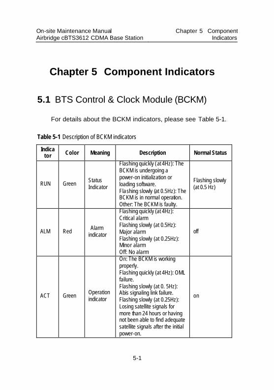
On-site Maintenance Manual Airbridge cBTS3612 CDMA Base Station
Chapter 5 Component Indicators
5-1
Chapter 5 Component Indicators
5.1 BTS Control & Clock Module (BCKM)
For details about the BCKM indicators, please see Table 5-1.
Table 5-1 Description of BCKM indicators
Indicator Color Meaning Description Normal Status
RUN Green Status Indicator
Flashing quickly (at 4Hz): The BCKM is undergoing a power-on initialization or loading software. Flashing slowly (at 0.5Hz): The BCKM is in normal operation. Other: The BCKM is faulty.
Flashing slowly (at 0.5 Hz)
ALM Red Alarm indicator
Flashing quickly (at 4Hz): Critical alarm Flashing slowly (at 0.5Hz): Major alarm Flashing slowly (at 0.25Hz): Minor alarm Off: No alarm
off
ACT Green Operation indicator
On: The BCKM is working properly. Flashing quickly (at 4Hz): OML failure. Flashing slowly (at 0. 5Hz): Abis signaling link failure. Flashing slowly (at 0.25Hz): Losing satellite signals for more than 24 hours or having not been able to find adequate satellite signals after the initial power-on.
on
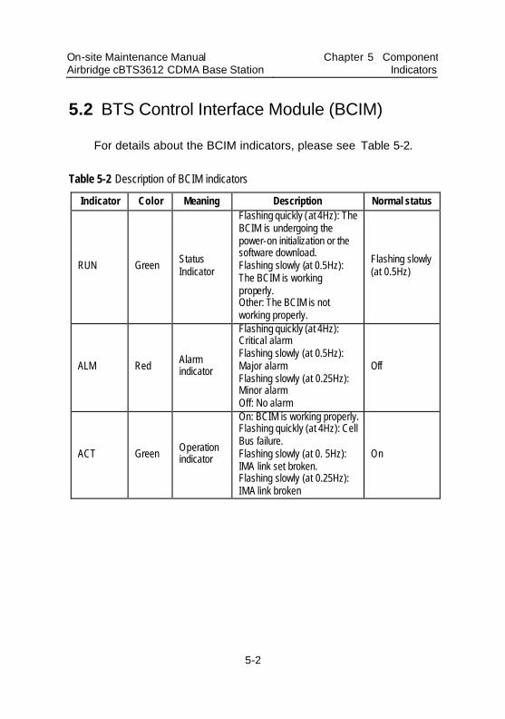
On-site Maintenance Manual Airbridge cBTS3612 CDMA Base Station
Chapter 5 Component Indicators
5-2
5.2 BTS Control Interface Module (BCIM)
For details about the BCIM indicators, please see Table 5-2.
Table 5-2 Description of BCIM indicators
Indicator Color Meaning Description Normal status
RUN Green Status Indicator
Flashing quickly (at 4Hz): The BCIM is undergoing the power-on initialization or the software download. Flashing slowly (at 0.5Hz): The BCIM is working properly. Other: The BCIM is not working properly.
Flashing slowly (at 0.5Hz)
ALM Red Alarm indicator
Flashing quickly (at 4Hz): Critical alarm Flashing slowly (at 0.5Hz): Major alarm Flashing slowly (at 0.25Hz): Minor alarm Off: No alarm
Off
ACT Green Operation indicator
On: BCIM is working properly. Flashing quickly (at 4Hz): Cell Bus failure. Flashing slowly (at 0. 5Hz): IMA link set broken. Flashing slowly (at 0.25Hz): IMA link broken
On
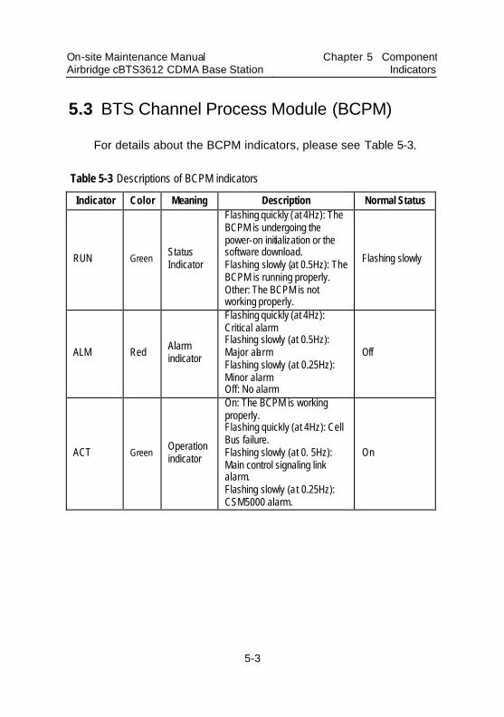
On-site Maintenance Manual Airbridge cBTS3612 CDMA Base Station
Chapter 5 Component Indicators
5-3
5.3 BTS Channel Process Module (BCPM)
For details about the BCPM indicators, please see Table 5-3.
Table 5-3 Descriptions of BCPM indicators
Indicator Color Meaning Description Normal Status
RUN Green Status Indicator
Flashing quickly (at 4Hz): The BCPM is undergoing the power-on initialization or the software download. Flashing slowly (at 0.5Hz): The BCPM is running properly. Other: The BCPM is not working properly.
Flashing slowly
ALM Red Alarm indicator
Flashing quickly (at 4Hz): Critical alarm Flashing slowly (at 0.5Hz): Major alarm Flashing slowly (at 0.25Hz): Minor alarm Off: No alarm
Off
ACT Green Operation indicator
On: The BCPM is working properly. Flashing quickly (at 4Hz): Cell Bus failure. Flashing slowly (at 0. 5Hz): Main control signaling link alarm. Flashing slowly (at 0.25Hz): CSM5000 alarm.
On
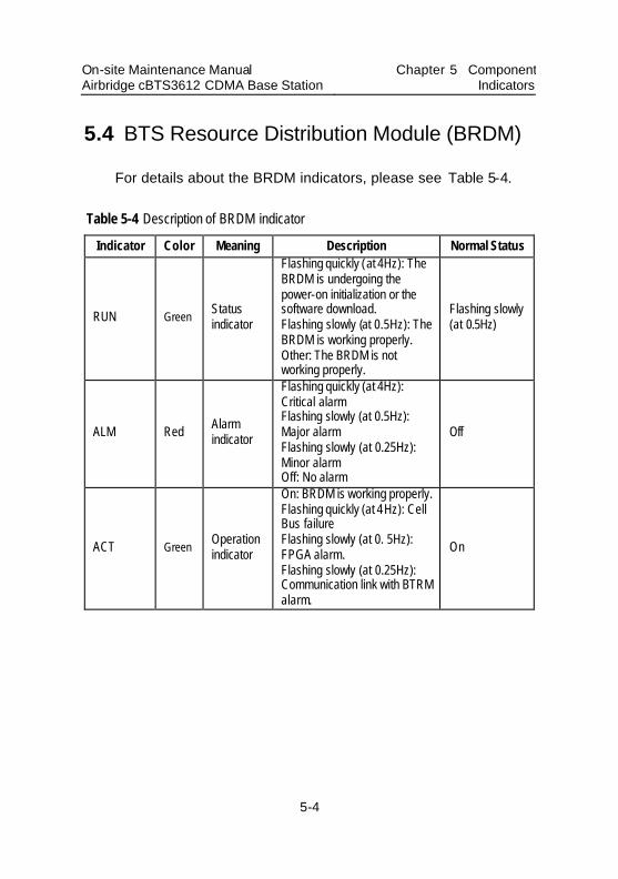
On-site Maintenance Manual Airbridge cBTS3612 CDMA Base Station
Chapter 5 Component Indicators
5-4
5.4 BTS Resource Distribution Module (BRDM)
For details about the BRDM indicators, please see Table 5-4.
Table 5-4 Description of BRDM indicator
Indicator Color Meaning Description Normal Status
RUN Green Status indicator
Flashing quickly (at 4Hz): The BRDM is undergoing the power-on initialization or the software download. Flashing slowly (at 0.5Hz): The BRDM is working properly. Other: The BRDM is not working properly.
Flashing slowly (at 0.5Hz)
ALM Red Alarm indicator
Flashing quickly (at 4Hz): Critical alarm Flashing slowly (at 0.5Hz): Major alarm Flashing slowly (at 0.25Hz): Minor alarm Off: No alarm
Off
ACT Green Operation indicator
On: BRDM is working properly. Flashing quickly (at 4Hz): Cell Bus failure Flashing slowly (at 0. 5Hz): FPGA alarm. Flashing slowly (at 0.25Hz): Communication link with BTRM alarm.
On
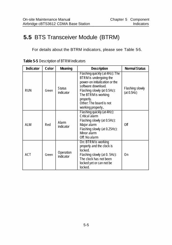
On-site Maintenance Manual Airbridge cBTS3612 CDMA Base Station
Chapter 5 Component Indicators
5-5
5.5 BTS Transceiver Module (BTRM)
For details about the BTRM indicators, please see Table 5-5.
Table 5-5 Description of BTRM indicators
Indicator Color Meaning Description Normal Status
RUN Green Status indicator
Flashing quickly (at 4Hz): The BTRM is undergoing the power-on initialization or the software download. Flashing slowly (at 0.5Hz): The BTRM is working properly. Other: The board is not working properly..
Flashing slowly (at 0.5Hz)
ALM Red Alarm indicator
Flashing quickly (at 4Hz): Critical alarm Flashing slowly (at 0.5Hz): Major alarm Flashing slowly (at 0.25Hz): Minor alarm Off: No alarm
Off
ACT Green Operation indicator
On: BTRM is working properly and the clock is locked. Flashing slowly (at 0. 5Hz): The clock has not been locked yet or can not be locked.
On
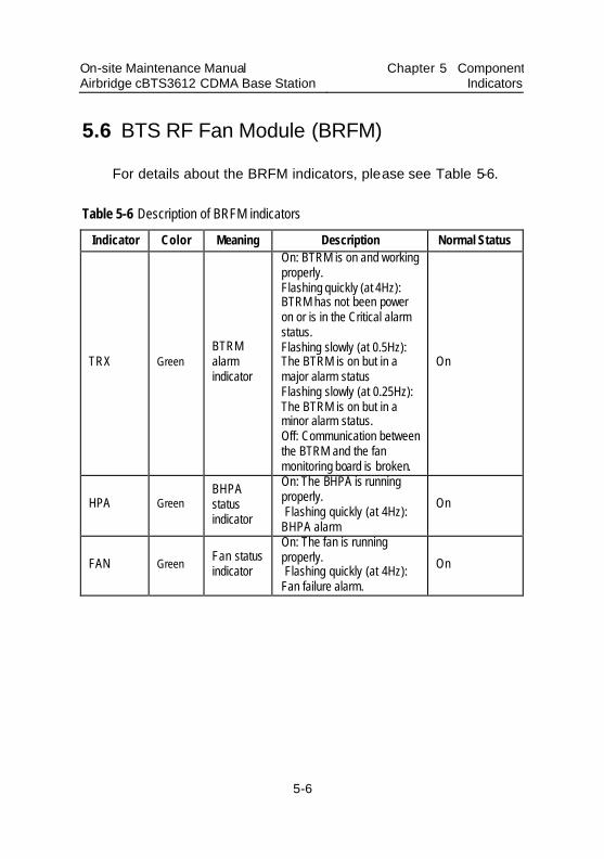
On-site Maintenance Manual Airbridge cBTS3612 CDMA Base Station
Chapter 5 Component Indicators
5-6
5.6 BTS RF Fan Module (BRFM)
For details about the BRFM indicators, please see Table 5-6.
Table 5-6 Description of BRFM indicators
Indicator Color Meaning Description Normal Status
TRX Green BTRM alarm indicator
On: BTRM is on and working properly. Flashing quickly (at 4Hz): BTRM has not been power on or is in the Critical alarm status. Flashing slowly (at 0.5Hz): The BTRM is on but in a major alarm status Flashing slowly (at 0.25Hz): The BTRM is on but in a minor alarm status. Off: Communication between the BTRM and the fan monitoring board is broken.
On
HPA Green BHPA status indicator
On: The BHPA is running properly. Flashing quickly (at 4Hz): BHPA alarm
On
FAN Green Fan status indicator
On: The fan is running properly. Flashing quickly (at 4Hz): Fan failure alarm.
On
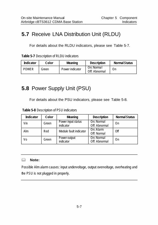
On-site Maintenance Manual Airbridge cBTS3612 CDMA Base Station
Chapter 5 Component Indicators
5-7
5.7 Receive LNA Distribution Unit (RLDU)
For details about the RLDU indicators, please see Table 5-7.
Table 5-7 Description of RLDU indicators
Indicator Color Meaning Description Normal Status
POWER Green Power indicator On: Normal Off: Abnormal
On
5.8 Power Supply Unit (PSU)
For details about the PSU indicators, please see Table 5-8.
Table 5-8 Description of PSU indicators
Indicator Color Meaning Description Normal Status
Vin Green Power input status indicator
On: Normal Off: Abnormal
On
Alm Red Module fault indicator On: Alarm Off: Normal
Off
Vo Green Power output indicator
On: Normal Off: Abnormal On
& Note:
Possible Alm alarm causes: input undervoltage, output overvoltage, overheating and
the PSU is not plugged in properly.
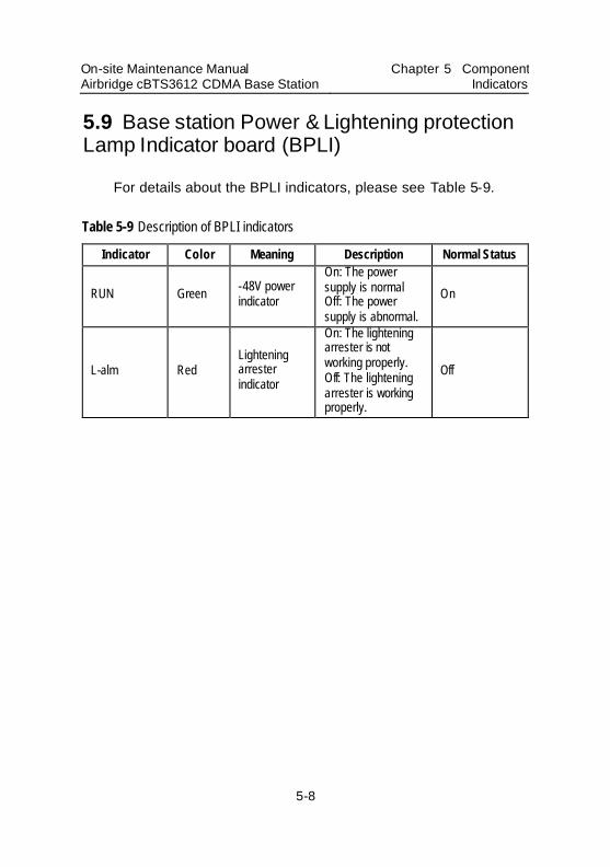
On-site Maintenance Manual Airbridge cBTS3612 CDMA Base Station
Chapter 5 Component Indicators
5-8
5.9 Base station Power & Lightening protection Lamp Indicator board (BPLI)
For details about the BPLI indicators, please see Table 5-9.
Table 5-9 Description of BPLI indicators
Indicator Color Meaning Description Normal Status
RUN Green -48V power indicator
On: The power supply is normal Off: The power supply is abnormal.
On
L-alm Red Lightening arrester indicator
On: The lightening arrester is not working properly. Off: The lightening arrester is working properly.
Off
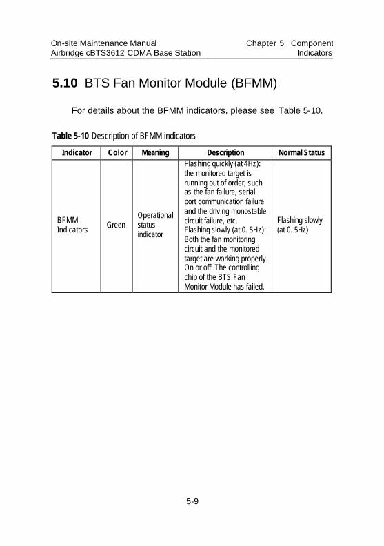
On-site Maintenance Manual Airbridge cBTS3612 CDMA Base Station
Chapter 5 Component Indicators
5-9
5.10 BTS Fan Monitor Module (BFMM)
For details about the BFMM indicators, please see Table 5-10.
Table 5-10 Description of BFMM indicators
Indicator Color Meaning Description Normal Status
BFMM Indicators Green
Operational status indicator
Flashing quickly (at 4Hz): the monitored target is running out of order, such as the fan failure, serial port communication failure and the driving monostable circuit failure, etc. Flashing slowly (at 0. 5Hz): Both the fan monitoring circuit and the monitored target are working properly. On or off: The controlling chip of the BTS Fan Monitor Module has failed.
Flashing slowly (at 0. 5Hz)
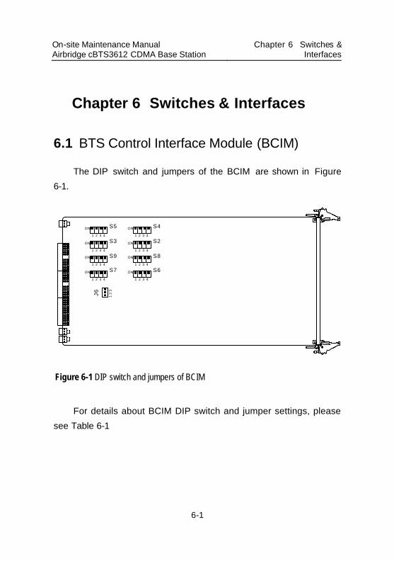
On-site Maintenance Manual Airbridge cBTS3612 CDMA Base Station
Chapter 6 Switches & Interfaces
6-1
Chapter 6 Switches & Interfaces
6.1 BTS Control Interface Module (BCIM)
The DIP switch and jumpers of the BCIM are shown in Figure 6-1.
S5ON
1 2 3 4
S3ON
1 2 3 4
S9ON
1 2 3 4
S7ON
1 2 3 4
S4ON
1 2 3 4
S2ON
1 2 3 4
S8ON
1 2 3 4
S6ON
1 2 3 4
J6 1 2
3
Figure 6-1 DIP switch and jumpers of BCIM
For details about BCIM DIP switch and jumper settings, please see Table 6-1
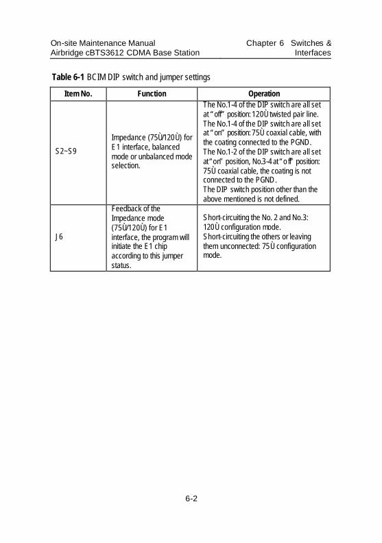
On-site Maintenance Manual Airbridge cBTS3612 CDMA Base Station
Chapter 6 Switches & Interfaces
6-2
Table 6-1 BCIM DIP switch and jumper settings
Item No. Function Operation
S2~S9
Impedance (75Ù/120Ù) for E1 interface, balanced mode or unbalanced mode selection.
The No.1-4 of the DIP switch are all set at “off” position: 120Ù twisted pair line. The No.1-4 of the DIP switch are all set at “on” position: 75Ù coaxial cable, with the coating connected to the PGND. The No.1-2 of the DIP switch are all set at “on” position, No.3-4 at “o ff” position: 75Ù coaxial cable, the coating is not connected to the PGND. The DIP switch position other than the above mentioned is not defined.
J6
Feedback of the Impedance mode (75Ù/120Ù) for E1 interface, the program will initiate the E1 chip according to this jumper status.
Short-circuiting the No. 2 and No.3: 120Ù configuration mode. Short-circuiting the others or leaving them unconnected: 75Ù configuration mode.
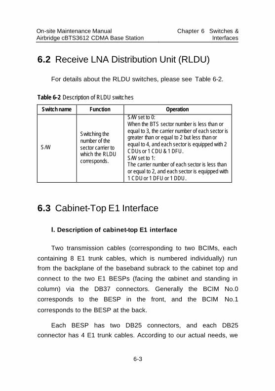
On-site Maintenance Manual Airbridge cBTS3612 CDMA Base Station
Chapter 6 Switches & Interfaces
6-3
6.2 Receive LNA Distribution Unit (RLDU)
For details about the RLDU switches, please see Table 6-2.
Table 6-2 Description of RLDU switches
Switch name Function Operation
S/W
Switching the number of the sector carrier to which the RLDU corresponds.
S/W set to 0: When the BTS sector number is less than or equal to 3, the carrier number of each sector is greater than or equal to 2 but less than or equal to 4, and each sector is equipped with 2 CDUs or 1 CDU & 1 DFU. S/W set to 1: The carrier number of each sector is less than or equal to 2, and each sector is equipped with 1 CDU or 1 DFU or 1 DDU.
6.3 Cabinet-Top E1 Interface
I. Description of cabinet-top E1 interface
Two transmission cables (corresponding to two BCIMs, each containing 8 E1 trunk cables, which is numbered individually) run from the backplane of the baseband subrack to the cabinet top and connect to the two E1 BESPs (facing the cabinet and standing in column) via the DB37 connectors. Generally the BCIM No.0 corresponds to the BESP in the front, and the BCIM No.1 corresponds to the BESP at the back.
Each BESP has two DB25 connectors, and each DB25 connector has 4 E1 trunk cables. According to our actual needs, we
On-site Maintenance Manual Airbridge cBTS3612 CDMA Base Station
Chapter 6 Switches & Interfaces
6-4
can run E1 trunk cables from one or all of these 4 DB25 connectors to the DDF rack in the cabinet room.
II. Caution-demanding issues
During the BTS capacity expansion or maintenance, we should have a clear idea which DB25 connector is being used. Incorrect cable connection will result in communication failure.
When the number of the E1 trunk cables actually used is less than 4, generally we should use the first DB25 connector of the front BESP (viewing from cabinet front); When the number of the E1 trunk cables actually used is greater than 4, we should pick up the DB25 connectors in a “from-front-to-back” order according to the actual capacity requirements.
On-site Maintenance Manual Airbridge cBTS3612 CDMA Base Station Table of contents
i
Table of Contents
Appendix A Common Commands............................................A-1
Appendix B Abbreviation.........................................................B-1
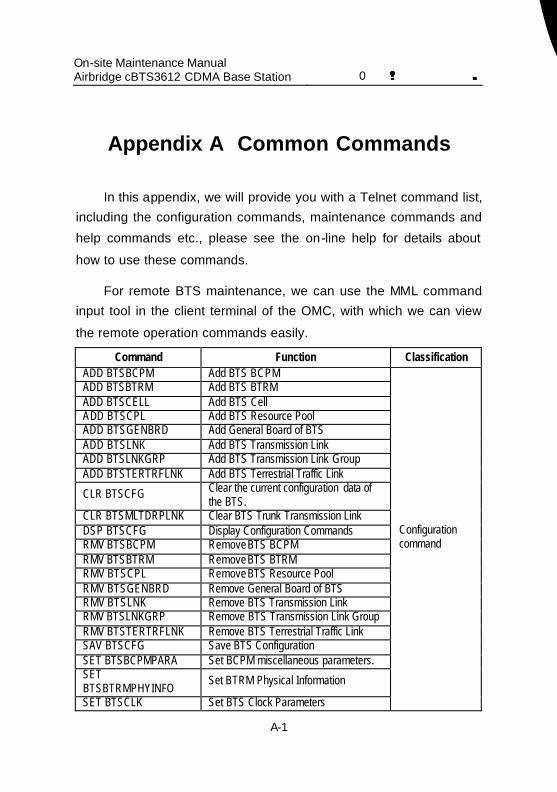
On-site Maintenance Manual Airbridge cBTS3612 CDMA Base Station 0错误 表格结果无效
A-1
Appendix A Common Commands
In this appendix, we will provide you with a Telnet command list, including the configuration commands, maintenance commands and help commands etc., please see the on-line help for details about how to use these commands.
For remote BTS maintenance, we can use the MML command input tool in the client terminal of the OMC, with which we can view the remote operation commands easily.
Command Function Classification ADD BTSBCPM Add BTS BCPM ADD BTSBTRM Add BTS BTRM
ADD BTSCELL Add BTS Cell ADD BTSCPL Add BTS Resource Pool ADD BTSGENBRD Add General Board of BTS ADD BTSLNK Add BTS Transmission Link ADD BTSLNKGRP Add BTS Transmission Link Group ADD BTSTERTRFLNK Add BTS Terrestrial Traffic Link
CLR BTSCFG Clear the current configuration data of the BTS.
CLR BTSMLTDRPLNK Clear BTS Trunk Transmission Link DSP BTSCFG Display Configuration Commands RMV BTSBCPM Remove BTS BCPM
RMV BTSBTRM Remove BTS BTRM RMV BTSCPL Remove BTS Resource Pool RMV BTSGENBRD Remove General Board of BTS RMV BTSLNK Remove BTS Transmission Link RMV BTSLNKGRP Remove BTS Transmission Link Group RMV BTSTERTRFLNK Remove BTS Terrestrial Traffic Link SAV BTSCFG Save BTS Configuration SET BTSBCPMPARA Set BCPM miscellaneous parameters. SET BTSBTRMPHYINFO
Set BTRM Physical Information
SET BTSCLK Set BTS Clock Parameters
Configuration command
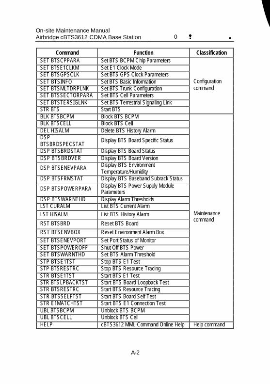
On-site Maintenance Manual Airbridge cBTS3612 CDMA Base Station 0错误 表格结果无效
A-2
Command Function Classification SET BTSCPPARA Set BTS BCPM Chip Parameters SET BTSE1CLKM Set E1 Clock Mode SET BTSGPSCLK Set BTS GPS Clock Parameters SET BTSINFO Set BTS Basic Information SET BTSMLTDRPLNK Set BTS Trunk Configuration SET BTSSECTORPARA Set BTS Cell Parameters SET BTSTERSIGLNK Set BTS Terrestrial Signaling Link STR BTS Start BTS
Configuration command
BLK BTSBCPM Block BTS BCPM BLK BTSCELL Block BTS Cell DEL HISALM Delete BTS History Alarm DSP BTSBRDSPECSTAT
Display BTS Board Specific Status
DSP BTSBRDSTAT Display BTS Board Status DSP BTSBRDVER Display BTS Board Version
DSP BTSENEVPARA Display BTS Environment Temperature/Humidity
DSP BTSFRMSTAT Display BTS Baseband Subrack Status
DSP BTSPOWERPARA Display BTS Power Supply Module Parameters
DSP BTSWARNTHD Display Alarm Thresholds LST CURALM List BTS Current Alarm LST HISALM List BTS History Alarm
RST BTSBRD Reset BTS Board
RST BTSENVBOX Reset Environment Alarm Box SET BTSENEVPORT Set Port Status of Monitor SET BTSPOWEROFF Shut Off BTS Power SET BTSWARNTHD Set BTS Alarm Threshold STP BTSE1TST Stop BTS E1 Test STP BTSRESTRC Stop BTS Resource Tracing STR BTSE1TST Start BTS E1 Test STR BTSLPBACKTST Start BTS Board Loopback Test STR BTSRESTRC Start BTS Resource Tracing STR BTSSELFTST Start BTS Board Self Test STR E1MATCHTST Start BTS E1 Connection Test UBL BTSBCPM Unblock BTS BCPM UBL BTSCELL Unblock BTS Cell
Maintenance command
HELP cBTS3612 MML Command Online Help Help command
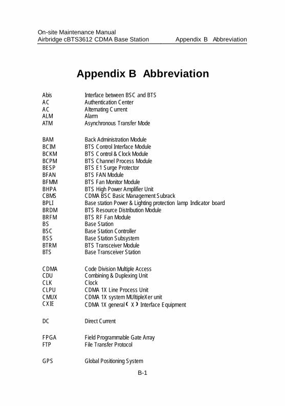
On-site Maintenance Manual Airbridge cBTS3612 CDMA Base Station Appendix B Abbreviation
B-1
Appendix B Abbreviation
Abis Interface between BSC and BTS AC Authentication Center AC Alternating Current ALM Alarm ATM Asynchronous Transfer Mode BAM Back Administration Module BCIM BTS Control Interface Module BCKM BTS Control & Clock Module BCPM BTS Channel Process Module BESP BTS E1 Surge Protector BFAN BTS FAN Module BFMM BTS Fan Monitor Module BHPA BTS High Power Amplifier Unit CBMS CDMA BSC Basic Management Subrack BPLI Base station Power & Lighting protection lamp Indicator board BRDM BTS Resource Distribution Module BRFM BTS RF Fan Module BS Base Station BSC Base Station Controller BSS Base Station Subsystem BTRM BTS Transceiver Module BTS Base Transceiver Station CDMA Code Division Multiple Access CDU Combining & Duplexing Unit CLK Clock CLPU CDMA 1X Line Process Unit CMUX CDMA 1X system MUltipleXer unit CXIE CDMA 1X general X Interface Equipment DC Direct Current FPGA Field Programmable Gate Array FTP File Transfer Protocol GPS Global Positioning System
On-site Maintenance Manual Airbridge cBTS3612 CDMA Base Station Appendix B Abbreviation
B-2
IMA Inverse Multiplexing for ATM IP Internet Protocol IPOA IP over ATM LMF Local Maintenance Function LNA Low-Noise Amplifier CLPU CDMA Line Process Unit MAC Medium Access Control MC Message Center MMI Man Machine Interface MML Man Machine Language Modem Modulator-Demodulator MPU Micro Process Unit MS Mobile Station NID Network Identification OMC Operation & Maintenance Center OML Operation & Maintenance Link OMU Operation & Maintenance Unit PSU Power Supply Unit PVC Permanent Virtual Channel PVP Permanent Virtual Path RLDU Receive LNA Distribution Unit RST Reset SID System Identification TCP Transport Control Protocol Um Interface between MS and BTS UNI User Network Interface VCI Virtual Channel Identifier VPI Virtual Path Identifier