human machine interface solution kit r0k5rx231d000br · r0k5rx231d000br (also referred to as the...
TRANSCRIPT
APPLICATION NOTE
R01AN2586EJ0102_RX231 Rev.1.02 Page 1 of 35
2016.12.01
RX231 Group
Human Machine Interface Solution Kit R0K5RX231D000BR
Overview
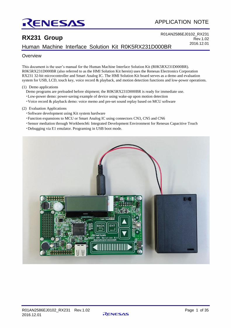
This document is the user’s manual for the Human Machine Interface Solution Kit (R0K5RX231D000BR).
R0K5RX231D000BR (also referred to as the HMI Solution Kit herein) uses the Renesas Electronics Corporation
RX231 32-bit microcontroller and Smart Analog IC. The HMI Solution Kit board serves as a demo and evaluation
system for USB, LCD, touch key, voice record & playback, and motion detection functions and low-power operations.
(1) Demo applications
Demo programs are preloaded before shipment; the R0K5RX231D000BR is ready for immediate use.
・Low-power demo: power-saving example of device using wake-up upon motion detection
・Voice record & playback demo: voice memo and pre-set sound replay based on MCU software
(2) Evaluation Applications
・Software development using Kit system hardware
・Function expansions to MCU or Smart Analog IC using connectors CN3, CN5 and CN6
・Sensor mediation through Workbench6: Integrated Development Environment for Renesas Capacitive Touch
・Debugging via E1 emulator. Programing in USB boot mode.
R01AN2586EJ0102_RX231
Rev.1.02
2016.12.01

RX231 Group Human Machine Interface Solution Kit R0K5RX231D000BR
R01AN2586EJ0102_RX231 Rev.1.02 Page 2 of 35
2016.12.01
Contents
1. Important Notes ................................................................................................................................. 4
2. Safety Items ...................................................................................................................................... 6 2.1. Definitions of Symbols ....................................................................................................................... 6 2.2. Warnings ........................................................................................................................................... 7 2.3. Cautions ............................................................................................................................................ 8
3. Specifications .................................................................................................................................... 9
4. Part Names ..................................................................................................................................... 11
4.1. RX231 and Expansion Connector Pin Assignments ....................................................................... 12 4.1.1. RX231 Pin Assignments ................................................................................................................. 12 4.1.2. Expansion Connector CN3 .............................................................................................................. 13 4.1.3. Expansion Connectors CN5 and CN6 ............................................................................................. 14
5. Operating Procedures ..................................................................................................................... 15 5.1. Power Supply at Startup ................................................................................................................. 15 5.1.1. Select Power Supply Input ............................................................................................................ 15 5.1.2. Select Startup Mode ........................................................................................................................ 15 5.1.3. Startup Procedure ........................................................................................................................... 16 5.2. Demo Operations ............................................................................................................................ 17 5.2.1. Normal Mode Operations ................................................................................................................ 17 5.2.1.1. Low-power demo: Demo1 (ECO) ................................................................................................. 18 5.2.1.2. Playback of preset voice data, Voice record & playback demo: Demo2 (SOUND) ..................... 19 5.2.1.3. Normal Mode: OTHER (Time setting) .......................................................................................... 23 5.2.1.4. Normal Mode: OTHER (Version Display) .................................................................................... 24 5.2.1.5. Normal Mode: OTHER (Timeout period selection) ...................................................................... 25 5.2.1.6. Normal Mode: OTHER (Pedometer) ............................................................................................ 26 5.2.1.7. Normal Mode: OTHER (Cap Touch Adjustments) ....................................................................... 27 5.2.1.8. Preparations of using Workbench6 (Connection with PC) ........................................................... 28 5.2.1.9. Preparations of using Workbench6 (USB driver Installation) .................................................... 29 5.2.2. Storage Mode Operations ............................................................................................................... 30 5.2.3. USB Boot Mode Operations ............................................................................................................ 31 5.3. E1 Connection ................................................................................................................................. 32
6. Notes when using expansion connectors CN3, CN5 and CN6 .. エラー! ブックマークが定義されて
いません。
7. Circuit Diagram ................................................................................................................................ 34
8. Component Layout Diagram ........................................................................................................... 34
9. Parts List ......................................................................................................................................... 34
Website and Support .................................................................................................................................. 35
RX231 Group Human Machine Interface Solution Kit R0K5RX231D000BR
R01AN2586EJ0102_RX231 Rev.1.02 Page 3 of 35
2016.12.01
Introduction
Thank you for purchasing the Renesas Electronics Corporation RX231 Human Machine Interface Solution Kit
(R0K5RX231D000BR).
Before using this kit, check the contents of the package as listed in the “Package Contents” section in the release notes
included with the product.
If you have any questions about this produce, contact Renesas Electronics Corporation, Renesas System Designs, or a
licensed distributor.
Related Manuals and Application Notes Refer to the manuals and application notes listed below as needed when using this product.
RX231 User’s Manual: Hardware (R01UH0496EJ)
http://www.renesas.com/products/mpumcu/rx/rx200/index.jsp
Renesas USB MCU USB Basic Mini Firmware (R01AN 2166EJ)
http://www.renesas.com/products/tools/middleware_and_drivers/c_driver/usb_driver/app_notes.jsp

RX231 Group Human Machine Interface Solution Kit R0K5RX231D000BR
R01AN2586EJ0102_RX231 Rev.1.02 Page 4 of 35
2016.12.01
1. Important Notes
Read this document carefully before using this product.
What this product is:
The term “this product” as used in this document refers to the following product manufactured by Renesas
Electronics Corporation. The term “this product” does not include the customer’s user systems or host machines.
a) RX231 Human Machine Interface Solution Kit (R0K5RX231D000BR)
Intended uses:
This product is a demo plus evaluation board product for demonstrating the features of the Renesas Electronics
Corporation RX231 32-bit microcontroller.
This product should only be used for these purposes.
Intended users: This product should only be used by persons who have read and understood this document. A basic knowledge of
electrical circuits, logic circuits, and microcontrollers is required to use this product.
When using this product: (1)Renesas assumes no responsibility for the results of customer development projects using this product.
(2)Renesas will, in response to defects or problems found in this produce, either suggest workarounds or repair said
defects, either for a fee or without charge. However, in no case will Renesas guarantee the suggested workaround or
repair.
(3)When this product is used in Japan, it is not subject to laws concerning electrical safety or electromagnetic
interference.
(4)Renesas cannot foresee all possible conditions or usages that have hidden dangers. Therefore, the warnings in this
document and the warnings attached as labels to the product do not cover all cases. The customer must take
responsibility for using this product safely.
(5)This product has not been approved under UL, or any other, safety standards, nor under IEC or other similar
standards. Therefore, if this product is transported outside Japan, the user must be fully aware of this point.
(6)This product may not be included in a user end product for mass production.
(7)If a problem occurs in a device included in this product, Renesas will not replace it with product in which the
device problem has been resolved.
(8)Operation with all connected USB devices is not guaranteed.
(9)The application notes and sample programs provided with this product are all provided for reference purposes
only. Their operation is not guaranteed. These should only be used as reference materials when the customer is
developing their own software.

RX231 Group Human Machine Interface Solution Kit R0K5RX231D000BR
R01AN2586EJ0102_RX231 Rev.1.02 Page 5 of 35
2016.12.01
Usage restrictions: This product may only be used for verifying the functions of the RX231 microcontroller.
Thus it may not be embedded in a customer’s end product for mass production. Furthermore, this product may not
be used for the following development purposes.
1. Transportation or mobile applications
2. Medical applications (equipment on which a human life depends)
3. Aerospace applications
4. Nuclear power control applications
5. Submarine repeater/relay applications
Customers who are considering these types of application should contact Renesas Electronics Corporation,
Renesas System Design, or a licensed distributor.
Product modifications: Renesas has a policy of continually improving this product. Therefore the specifications, design, and documentation
of this product are subject to change without notice.
Rights: 1. Renesas will accept no responsibility for any damage, or any infringement of patent or any other rights, arising
from the use of any information included in this document, or the use of this product or these circuits.
2. This document does not grant the user any license for patent rights or any other rights belonging to Renesas or
any third party.
3. All rights concerning this document and this product (R0K5RX231D000BR) remain the property of Renesas
Electronics Corporation.
Figures: Parts of the figures in this document may differ from the actual product.
Guarantee: Renesas will replace this product without charge if any defect is found within one month of purchase.
In all other cases, this product is provided "as is" and no repair, analysis, etc. are supported.

RX231 Group Human Machine Interface Solution Kit R0K5RX231D000BR
R01AN2586EJ0102_RX231 Rev.1.02 Page 6 of 35
2016.12.01
2. Safety Items
2.1. Definitions of Symbols
A variety of symbols are used in this document and on the product itself to prevent in advance danger to you the
user or any third parties and to prevent in advance damage to any physical property.
This section, Safety Items, presents these symbols and their meanings. It also presents safety notes to assure that
this produce is used safely and correctly.
This product should only be used after fully understanding the material presented in this section.
Warning
Warning items indicate things that, if not avoided, could lead to death or
serious injury.
Caution
Caution items indicate both latent dangers that can lead to minor or
moderately severe injury and latent dangers that can lead to property
damage if not avoided.
In addition to the above two markings, the following are displayed at the same time if appropriate.
[Important] Indicates a point that can lead to equipment failure or malfunction if incorrectly set when setting up this
product.
A triangular mark indicates a warning or caution. Example:
Electrical Shock Hazard The mark indicates something that is forbidden. Example:
Do Not Disassemble
RX231 Group Human Machine Interface Solution Kit R0K5RX231D000BR
R01AN2586EJ0102_RX231 Rev.1.02 Page 7 of 35
2016.12.01
2.2. Warnings
Warning
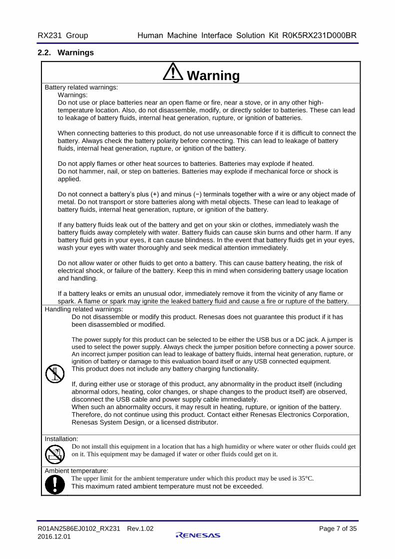
Battery related warnings: Warnings:
Do not use or place batteries near an open flame or fire, near a stove, or in any other high-temperature location. Also, do not disassemble, modify, or directly solder to batteries. These can lead to leakage of battery fluids, internal heat generation, rupture, or ignition of batteries. When connecting batteries to this product, do not use unreasonable force if it is difficult to connect the battery. Always check the battery polarity before connecting. This can lead to leakage of battery fluids, internal heat generation, rupture, or ignition of the battery. Do not apply flames or other heat sources to batteries. Batteries may explode if heated. Do not hammer, nail, or step on batteries. Batteries may explode if mechanical force or shock is applied. Do not connect a battery’s plus (+) and minus (−) terminals together with a wire or any object made of metal. Do not transport or store batteries along with metal objects. These can lead to leakage of battery fluids, internal heat generation, rupture, or ignition of the battery. If any battery fluids leak out of the battery and get on your skin or clothes, immediately wash the battery fluids away completely with water. Battery fluids can cause skin burns and other harm. If any battery fluid gets in your eyes, it can cause blindness. In the event that battery fluids get in your eyes, wash your eyes with water thoroughly and seek medical attention immediately. Do not allow water or other fluids to get onto a battery. This can cause battery heating, the risk of electrical shock, or failure of the battery. Keep this in mind when considering battery usage location and handling. If a battery leaks or emits an unusual odor, immediately remove it from the vicinity of any flame or spark. A flame or spark may ignite the leaked battery fluid and cause a fire or rupture of the battery.
Handling related warnings:
Do not disassemble or modify this product. Renesas does not guarantee this product if it has been disassembled or modified. The power supply for this product can be selected to be either the USB bus or a DC jack. A jumper is used to select the power supply. Always check the jumper position before connecting a power source. An incorrect jumper position can lead to leakage of battery fluids, internal heat generation, rupture, or ignition of battery or damage to this evaluation board itself or any USB connected equipment.
This product does not include any battery charging functionality. If, during either use or storage of this product, any abnormality in the product itself (including abnormal odors, heating, color changes, or shape changes to the product itself) are observed, disconnect the USB cable and power supply cable immediately. When such an abnormality occurs, it may result in heating, rupture, or ignition of the battery. Therefore, do not continue using this product. Contact either Renesas Electronics Corporation, Renesas System Design, or a licensed distributor.
Installation:
Do not install this equipment in a location that has a high humidity or where water or other fluids could get
on it. This equipment may be damaged if water or other fluids could get on it.
Ambient temperature:
The upper limit for the ambient temperature under which this product may be used is 35°C.
This maximum rated ambient temperature must not be exceeded.

RX231 Group Human Machine Interface Solution Kit R0K5RX231D000BR
R01AN2586EJ0102_RX231 Rev.1.02 Page 8 of 35
2016.12.01
2.3. Cautions
Caution
Handling:
This product must be handled carefully. Do not drop, knock over, or apply any strong mechanical shocks to this product. Do not touch this product’s connectors or component pins with bare hands. Internal components may be damaged by electrostatic discharge. When connecting or disconnecting cables from this product, hold the parts of the cable intended to be grasped (such as the plugs) and avoid putting stress on the cable. Do not pull on this product when it is connected to a communications cable or user system connection cable. Stress on the cable can result in internal disconnections in the cable. When connecting a cable to a connector, be careful not to insert the plug in the reverse orientation. Reverse insertion can result in damage to this product itself or to connected equipment. The power supply for this product can be selected from two options (the provided battery box or the USB cable). The jumper J1 (on the back side of the circuit board) is used to select the power supply. Always check the jumper position before connecting a power source. An incorrect jumper position can result in damage to this product or the PC connected over the USB cable. Do not handle this product with wet hands. This can lead to failure of the product.
Transport methods:
When transporting this product, use the product’s packing box and cushioning materials and ship it with precision equipment handling. If the products packing is insufficient, it may be damaged during shipping. If it must be transported by some other method, pack it carefully as precision equipment. When packing this product, always use the antistatic pouch included with this product. If some other pouch is used, damage to the product may be caused by electrostatic discharge.
Abnormal operation:
If operation of this product becomes abnormal due to interference from, for example, external noise, apply the following procedure. 1. Turn off the power. 2. Wait 10 seconds and then turn the power back on.
Disposal:
When disposing of this product, handle it as industrial waste according to all applicable laws. To dispose of batteries, follow the instructions of the local government that collects batteries for disposal or recycling
European Union regulatory notices:
The WEEE (Waste Electrical and Electronic Equipment) regulations put responsibilities on
producers for the collection and recycling or disposal of electrical and electronic waste. Return of
WEEE under these regulations is applicable in the European Union only. This equipment
(including all accessories) is not intended for household use. After use the equipment cannot
be disposed of as household waste, and the WEEE must be treated, recycled and disposed of in
an environmentally sound manner.
Renesas Electronics Europe GmbH can take back end of life equipment, register for this service
at “http://www.renesas.eu/weee”.

RX231 Group Human Machine Interface Solution Kit R0K5RX231D000BR
R01AN2586EJ0102_RX231 Rev.1.02 Page 9 of 35
2016.12.01
3. Specifications
Hardware specifications for R0K5RX231D000BR are shown in Table 3.1 and the functions realized by the product
using the MCU software included in this product are described in general in Table 3.2.
Table 3.1 Hardware Specifications
Item Description Remarks
Catalog number R0K5RX231D000BR
Power supply
[1]DC jack (J1) Center plus
a. Battery box (three AA batteries) b. AC adapter (sold separately) *1
Select [1] or [2] using JP1 jumper. Refer to 5.1.1 for details.
[2]USB micro-B (CN2) c. USB bus-powered
Input voltage 3.5V-5.5V
Current drain Max: 300mA
Dimensions Main unit: 120 x 70×27mm, Battery box: 70 x 48 x 20mm
Environmental conditions
Operating: 10 to 35°C, storage: 10 to 50°C No condensation
Microcontroller R5F52318ADFP(ROM:512KB, RAM:64KB, 100LQFP) RX231
Smart Analog IC RAA7301013CBG SAIC101
Flash memory MX25L6433FM2I-08G (64Mbit) SPI communication
Standard interface USB Standard-A (CN1) Refer to Note 2, Note 4
USB micro-B 8 CN2) Refer to Note 4
Evaluation interface CN3: for wireless module evaluation (24 5602 024 000 829 H+) CN5,CN6: for function expansion (2.54mm pitch through-hole)
Refer to Note 2
Debugging interface E1 connector (CN4) Refer to section 5.3
Sensors Pyroelectric infrared sensor Detected by SAIC101
Acceleration sensor Detected by MCU
Display LCD displays: 1 (16 characters x 2 lines) I2C communication
LED displays: 2, (LED1 - green, LED2 - orange)
Key input
Cap touch (4 buttons, 1 slider)
Mechanical push button (interrupt : SW1, reset: SW3) Mechanical slide (mode switch: SW2, USB boot: SW4)
Voice record/playback (S/W
encoding/decoding)
Playback
1.2 W power amp (TS4990IST) Circuit board mounted speaker or earphone jack (J3, φ3.5mm, monaural) Refer to Note 3
Recording Capacitor microphone, Op-amp (HA1630D06TEL-E)
Music playback 16-bit audio DAC ((PCM1774RGPT) 40mW+40mW headphone output (J2, φ3.5mm, stereo)
Refer to Note 2
Current measurement Current measurement of Board power supply (3.2V)
Oscillation device Oscillator: 16 MHz, 32.768kHz; oscillation (module) 11.2896MHz
Note 1: When using an AC adapter, make sure it meets the following specifications:
Plug shape: external diameter 5.5mm, internal diameter 2.1mm
Electrical specifications: 5V±5%, 0.5A or higher, Center plus
Modifying the software (especially values corresponding to the USB host) will change current consumption as well. Make
sure current specification meets all requirements.
Note 2: Not supported by the standard software included in this product. The user must provide the appropriate software to use this
function.
Note 3: The volume adjustment knobs VR1 and VR2 reduce volume when turned to the left and increase volume when turned to the
right. Turning this knob beyond its normal range of operation will cause damage to the product. Do not use excessive force
when using.
Note 4: Don’t connect USB cable to CN1 and CN2 at the same time. This can lead to failure of the product.

RX231 Group Human Machine Interface Solution Kit R0K5RX231D000BR
R01AN2586EJ0102_RX231 Rev.1.02 Page 10 of 35
2016.12.01
Table 3.2 Function Outline (Software Version: V1.00)
Item Description Remarks
Startup modes
(select from three types)
1) Normal mode
Demo applications can be used on the HMI Solution Kit as is.
Connect the board to the user PC with a USB connection to employ
Workbench6 (Integrated Development Environment for Renesas
Capacitive Touch) (Note 1). Select the operating mode at
startup.
Refer to section 5.1.2
2) Storage mode
The on-board flash memory can be used as a USB memory when
the board and user PC are connected with a USB connection.
3) USB boot mode
MCU’s can be reprogrammed using the Renesas FLASH
Programmer when the board and PC are connected using a USB
connection. (Note 2)
Startup mode descriptions Refer to section 5.2
1) Normal mode Refer to section 5.2.1
Low-power demo
Low-power operations demonstration using a motion detection sensor
(pyroelectric infrared sensor, acceleration sensor)
・Normal operating state: all board internal power supplies are set to
ON.
If motion is not detected for the set period, the mode goes to low-
power 1 state.
・Low-power 1 state: LCD display back lighting turns off.
If motion is not detected for another set period, the mode goes to
low-power 2.
Returns to normal operating mode when motion is detected.
・Low-power 2 state:Suppresses power consumption for some of the
embedded circuits to a level even lower than low-power 1 state.
Press SW1 to return to normal operating mode.
Refer to section 5.2.1.1
LCD indicates consumption
current of board’s internal
power supply (3.2V).
Use SW2 to enable/disable
motion detection function of
pyroelectric infrared sensor.
Voice recording demo
a. Voice playback
Plays back voice data stored in MCU memory before product
shipment. (Note 3).
Refer to section 5.2.1.2
b. Voice record/playback
Records up to 10 seconds of voice with on-board microphone, and
plays back recorded voice.
Recorded data is stored in flash memory.
Refer to section 5.2.1.2
System controls
a. Time setting Refer to section 5.2.1.3
b. Software version confirmation Refer to section 5.2.1.4
c. Low-power state transition time selection Refer to section 5.2.1.5
d. Pedometer Refer to section 5.2.1.6
e. Touch key adjustments Refer to section 5.2.1.7
2) Storage mode *Same as “Startup modes” above. Refer to section 5.2.2
3) USB boot mode *Same as “Startup modes” above. Refer to section 5.2.3
Note 1: Refer to Renesas website for details on Workbench6 (Integrated Development Environment for Renesas Capacitive Touch).
http://renesas.com/applications/key_technology/human_interface/touch_sensor_system_2gen/child/technology_child.jsp
Note 2: Refer to Renesas website for details on Renesas FLASH Programmer.
http://www.renesas.com/products/tools/flash_prom_programming/rfp/index.jsp
Note 3: Renesas Electronics Corporation holds all rights to the voice data provided with this product. Use of this voice data anywhere
else is strictly prohibited.

RX231 Group Human Machine Interface Solution Kit R0K5RX231D000BR
R01AN2586EJ0102_RX231 Rev.1.02 Page 11 of 35
2016.12.01
4. Part Names
Figure 4.1 Circuit Board Part Names
JP1 (power supply select)1-2: DC jack2-3: USB micro-B
SW1 (interrupt)
SW2 (mode select)
LCD
LED1 LED2CN6 (expansion connector)
Pyroelectric infrared sensor
Cap touch buttons (4)
Cap touch slider CN1 (USBStandard-A)
CN5 (expansion connector)
VR2(voice volume)
U1 Smart Analog IC(SAIC101)
Speaker
Capacitor microphone
Acceleration sensor
U2RX231
CN4 (E1 connector) SW3 (reset)
CN3 (expansion connector)
J1(DC jack) power supply input
J2 (stereo jack) J3(monaural jack)
SW4(USB boot select)
CN5 (expansion connector)
CN6 (expansion connector)
VR1(microphone volume)
Flash memory
Audio DAC
CN2 (USBmicro-B)
Top side of board
Back side of board

RX231 Group Human Machine Interface Solution Kit R0K5RX231D000BR
R01AN2586EJ0102_RX231 Rev.1.02 Page 12 of 35
2016.12.01
4.1. RX231 and Expansion Connector Pin Assignments
The HMI Solution kit is equipped with expansion connectors (CN3, CN5, and CN6) for function expansion and user
evaluation.
4.1.1. RX231 Pin Assignments
Table 4.1 RX231 Pin Assignments
Pin No.
Pin Name (Note 1) Pin No.
Pin Name (Note 1) Pin No.
Pin Name (Note 1) Pin No.
Pin Name (Note 1)
1 VREFH 26 CN5:7 51 PC1 76 CN6:7
2 DA0 27 Test PAD 52 PC0 77 CN6:8
3 VREFL 28 Test PAD 53 SMOSI9 78 CN6:9
4 MTIOC3C 29 Test PAD 54 SMISO9 79 Test PAD
5 VCL 30 USB0_VBUS 55 SCK9 80 Unused pin (Note 2)
6 VBATT 31 Test PAD 56 PB4 81 IRQ5
7 MD/FINE 32 USB0_OVRCURA 57 PB3 82 Test PAD
8 XCIN 33 P13 58 PB2 83 CN5:6
9 XCOUT 34 CN5:3 59 SSDA6 84 PD2
10 RES# 35 VCC_USB 60 VCC 85 IRQ1
11 XTAL 36 USB_DM 61 SSCL6 86 IRQ0
12 VSS 37 USB_DP 62 VSS 87 AN007
13 EXTAL 38 VSS_USB 63 PA7 88 AN006
14 VCC 39 TS15 64 SSIWS0 89 AN005
15 UPSEL 40 TS16 65 PA5 90 AN004
16 CN5:5 41 TS17 66 SSITXD0 91 AN003
17 CN5:4 42 TS18 67 PA3 92 CN5:16
18 USB0_VBUSEN 43 TS19 68 PA2 93 CN5:15
19 CN5:12 44 TS20 69 SSISCK0 94 VREFL0
20 CN5:10 45 UB 70 CN6:10 95 AN000
21 CN5:13 46 TS22 71 CN6:6 96 VREFH0
22 CN5:14 47 TS23 72 CN6:5 97 AVCC0
23 CN5:11 48 TSCAP 73 CN6:4 98 Test PAD
24 CN5:9 49 CN3:10(TXD5) 74 CN6:3 99 AVSS0
25 CN5:8 50 CN3:12(RXD5) 75 AUDIO_MCLK 100 DA1
Note 1: Pin names indicated here are specific to this product.
Refer to the RX231hardware manual for explanation of the RX231 pin functions.
Note 2: In product’s default state, the open pin can be wired as CN3:16 by mounting a resistor.

RX231 Group Human Machine Interface Solution Kit R0K5RX231D000BR
R01AN2586EJ0102_RX231 Rev.1.02 Page 13 of 35
2016.12.01
4.1.2. Expansion Connector CN3
The CN3 connector is manufactured by Kyosera (type number: 24 5602 024 000 829 H+).
Table 4.2 CN3 Pin Assignments
Pin No
Connection Destination Remarks Pin No
Connection Destination Remarks
1 DGND Digital GND 2 DVCC Digital power supply (3.2V)
3 - 4 -
5 - 6 -
7 RESET Board reset 8 -
9 - 10 U1:49
11 - 12 U1:50
13 - 14 -
15 - 16 - When R48 is mounted: U1:80 (Note 1)
17 - 18 -
19 - 20 - Test PAD
21 DGND 22 -
23 - 24 DVCC Digital power supply (3.2V)
“-” indicates the pin is not connected.
Note 1: Mount a 0Ω resistor as noted in the comments to connect to signal U1.

RX231 Group Human Machine Interface Solution Kit R0K5RX231D000BR
R01AN2586EJ0102_RX231 Rev.1.02 Page 14 of 35
2016.12.01
4.1.3. Expansion Connectors CN5 and CN6
CN5 and CN6 are 2.54mm-pitch, double-row through-hole connectors.
Table 4.3 CN5 Pin Assignments
Pin No Connection Destination Remarks Pin No Connection Destination Remarks
1 DVCC Digital power supply (3.2V) 2 DGND Digital GND
3 U1:34 4 U1:17
5 U1:16 6 U1:83
7 U1:26 8 U1:25
9 U1:24 10 U1:20
11 U1:23 12 U1:19
13 U1:21 14 U1:22
15 U1:93 16 U1:92
17 - When R53 is mounted: U1:91
(Note 1) 18 -
19 - 20 -
“-” indicates the pin is not connected.
Note 1: Mount a 0Ω resistor as noted in the comments to connect to signal U1.
Table 4.4 CN6 Pin Assignments
Pin No
Connection Destination Remarks Pin No
Connection Destination Remarks
1 DVCC Digital power supply (3.2V) 2 DGND Digital GND
3 U1:74 4 U1:73
5 U1:72 6 U1:71
7 U1:76 8 U1:77
9 U1:78 10 U1:70
11 U2:D6 AIN2P-R37-GND (Note 1) 12 U2:C6 AIN2N-R39-GND (Note 1)
13 U2:F4 AIN3P-R40-GND (Note 1) 14 U2:E5 AIN3N-R41-GND (Note 1)
15 U2:F3 ANI4P-R42-GND (Note 1) 16 U2:E4 AIN4N-R43-GND (Note 1)
“-” indicates the pin is not connected.
Note 1: Connected to GND through a 0Ω resistor before shipment (process pin when not in use).
When using this pin, remove resistor as noted in remarks.
RX231 Group Human Machine Interface Solution Kit R0K5RX231D000BR
R01AN2586EJ0102_RX231 Rev.1.02 Page 15 of 35
2016.12.01
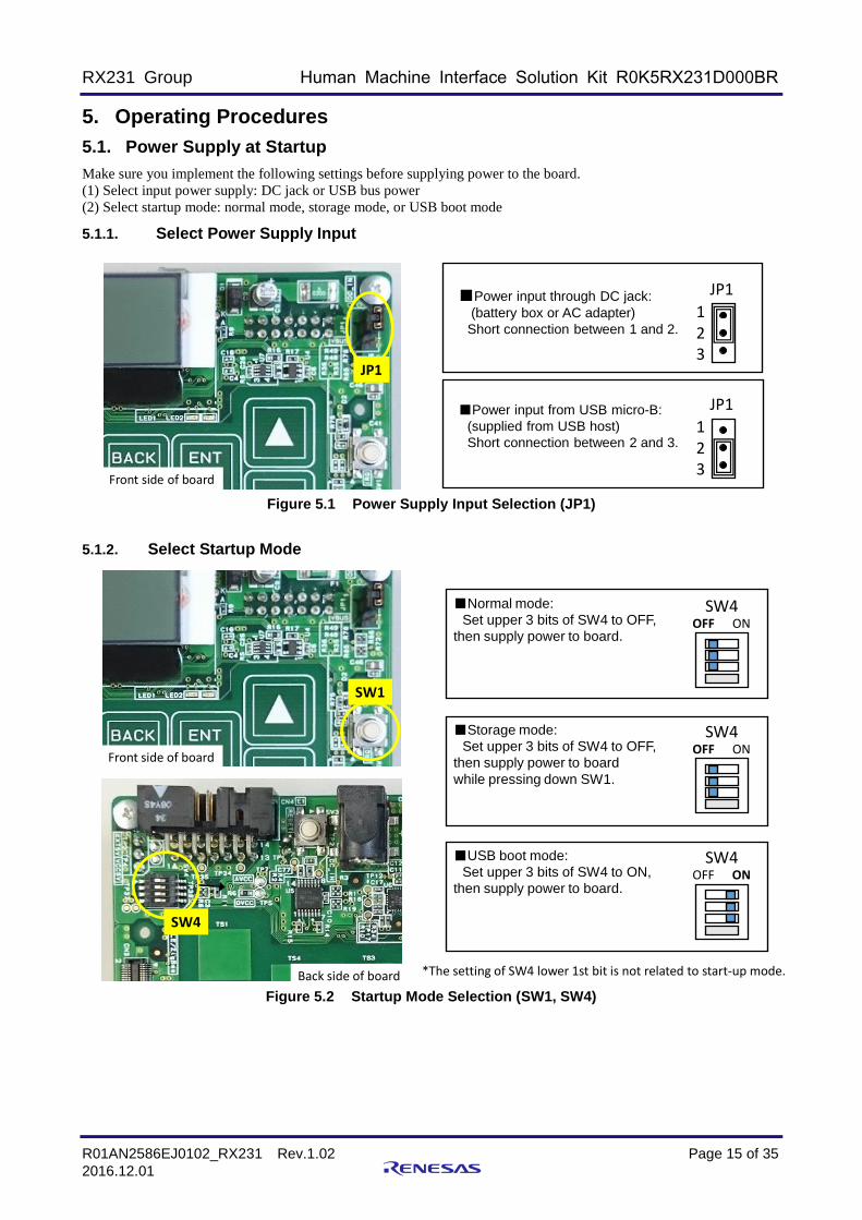
5. Operating Procedures
5.1. Power Supply at Startup
Make sure you implement the following settings before supplying power to the board.
(1) Select input power supply: DC jack or USB bus power
(2) Select startup mode: normal mode, storage mode, or USB boot mode
5.1.1. Select Power Supply Input
Figure 5.1 Power Supply Input Selection (JP1)
5.1.2. Select Startup Mode
Figure 5.2 起動モードの選択(SW1、SW4)
Figure 5.2 Startup Mode Selection (SW1, SW4)
123
JP1■Power input through DC jack:
(battery box or AC adapter)
Short connection between 1 and 2.
■Power input from USB micro-B:
(supplied from USB host)
Short connection between 2 and 3.123
JP1
Front side of board
JP1
SW4■Normal mode:
Set upper 3 bits of SW4 to OFF,
then supply power to board.
■Storage mode:
Set upper 3 bits of SW4 to OFF,
then supply power to board
while pressing down SW1.
Back side of board
SW4
OFF ON
SW4OFF ON
■USB boot mode:
Set upper 3 bits of SW4 to ON,
then supply power to board.
SW4OFF ON
SW1
*The setting of SW4 lower 1st bit is not related to start-up mode.
Front side of board

RX231 Group Human Machine Interface Solution Kit R0K5RX231D000BR
R01AN2586EJ0102_RX231 Rev.1.02 Page 16 of 35
2016.12.01
5.1.3. Startup Procedure
After setting the power supply as described in section 5.1.1 Select Input Power Supply above, start up the board with
the following procedure. Select the operating mode for the power supply startup according to the description in section
5.1.2 Select Startup Mode, above.
(1) Battery box or AC adapter power supply (JP1: short pins 1-2)
・ Battery box
Place three AA batteries in the battery box.
Insert the battery box plug into the DC jack (J1) on the back side of the board. Set the battery box switch to ON to
turn on the board.
・ AC adapter
The user will need to supply an AC adapter as this kit does include one (Refer to section 3. Specifications).
Insert the AC adapter plug into the DC jack (J1) on the back of the board and the board will immediately turn on.
Figure 5.3 Battery Box or AC Adaptor Connection
(2) USB Host Device Bus Power Supply (JP1: short pin 2-3)
A USB cable is not included in the kit and must be provided by the user. This board is equipped with a micro-B
connector. Insert the cable to the connector, located on the back side of the board. Note: the USB Standard-A
connector located on the top side of the board cannot be used for power supply.
Make sure you have the appropriate connector to fit the USB host device that serves as the power supply source.
Connect the USB cable between the USB host device and the board to start up the board.
Figure 5.4 USB Cable Connection
DC jack (J1) on back of board
Connect the battery box (included in kit) or
AC adaptor (not included).
*The kit does not include batteries and
must be provided by the user.
USB host device example: computerUSB-microB
Back side of board

RX231 Group Human Machine Interface Solution Kit R0K5RX231D000BR
R01AN2586EJ0102_RX231 Rev.1.02 Page 17 of 35
2016.12.01
5.2. Demo Operations
The HMI Solution Kit supports three startup modes (normal mode/storage mode/USB boot mode), as described in
Table 3.2.
This section describes how to operate the HMI Solution Kit in either normal or storage mode using the MCU software
(V1.00) that comes standard with the kit.
To use the product in USB boot mode, refer to the Renesas FLASH Programmer explanation on the Renesas website. http://www.renesas.com/products/tools/flash_prom_programming/rfp/index.jsp
5.2.1. Normal Mode Operations
The following describes operations when the board is started up in the normal mode. Refer to section 5.1.2 for
instructions on how to start up the board.
An outline of operations is provided in Figure 5.5, followed by detailed explanations for Demo 1: ECO, Demo 2:
SOUND, and OTHER.
Figure 5.5 Outline of Operations in Normal Mode
3 second wait
Power supply startup
*Board startup settings:SW1=OFF, upper 3 bits of SW4 = OFF
Initial display
Demo 1: ECO(sensor & low power)
ECO-1Low-power 1
ECO-2Low-power 2
Timeout
Motion detection A
Motion detection B「>>>」
Slide righ
t
TALKData Select
and Talk
REC Record
Playback
Select datawith ▲ or ▼Press [ENT]
to set.Return with
[BACK]
Select datawith ▲ or ▼Press [ENT] to
set.
Select datawith ▲ or ▼Press [ENT] to
set.
「>>>」Slid
e right
「<<<」Slid
e left「<<<
」Slid
e left
「>>>」Slid
e right
「<<<」Slide left
Time
Ver
Timeout
Walk
Demo 2: SOUND(Voice record &
playback)
OTHER
Select datawith ▲ or ▼Press [ENT]
to set.Return with
[BACK]
Displays/sets time.
Displays software version.
Selects Demo 1 “Timeout.”(1 minute or 5 seconds)
Timeout
Starts pedometer.Confirms 5 days of data.
Supplement (Demo 1)Timeout: select with OTHER (1 min/5 sec)Human Detection A: Detected though board vibration, SW1 press, or change in ambient temp.Human Detection B : Detected through board vibration or SW1 press
BACK ENT
▲
▼
Slide right >>><<< Slide left
■Key definitions
・Playback pre-set voice data
・Record voice・Playback recorded data
TouchFor cap touch sensitivity adjustments.Cap touch elements emit sound indicating response.*This mode returns to OTHER when SW1 is pressed.

RX231 Group Human Machine Interface Solution Kit R0K5RX231D000BR
R01AN2586EJ0102_RX231 Rev.1.02 Page 18 of 35
2016.12.01
5.2.1.1. Low-power demo: Demo1 (ECO)
Demo 1: ECO starts automatically 3 seconds after the board is started up in normal mode.
This function demonstrates the device’s transition to low-power operations triggered by the motion sensor.
When motion is not detected for a set period (1 minute or 5 seconds), the function stops and the device goes to low-
power state (second level).
The pyroelectric infrared sensor used for motion detection senses change within the infrared detection range. Therefore,
the device will not transition to the low-power state if a person is located nearby. To disable detection based on the
pyroelectric infrared sensor, set SW2 to “Mode2” and use appropriately.
Figure 5.6 Demo 1: ECO in Normal Mode
(1) Initial display after startup in normal mode
■Demo 1 (ECO) start
(2) Normal power
ECO 12:00 xxxmA
Demo 1 (ECO) starts automatically after 3 seconds.
ECO-1 12:00 xxxmA
RENESAS RX231 HMI Solution Kit
Transitions to Demo 1 (ECO)/Demo2 (SOUND)/OTHER
by sliding right [>>>] or left [<<<].
Timeout period (Note 1) passes.
(3) Low-power 1 (Circuit off: LCD backlight)
Transitions to “(2) Normal power” triggered by motion detection A
(the following three 3 items below)
・Infrared change (note 2) detected by pyroelectric infrared sensor
・Board vibration detected by acceleration sensor
・SW1 pressed down
ECO-2 12:00 xxxmA
Timeout period (Note 1) passes.
(4) Low-power 2 (Circuits off: LCD backlight, touch key, SAIC101, voice amp, microphone power)
Transition to “(2) Normal power” triggered by motion detection B
(the following 2 items below)
・Board vibration detected by acceleration sensor
・SW1 pressed down
Note 1: Default value of timeout period is 1 minute. Set to 5 seconds with “OTHER.”
Note 2: Set SW2 to “Mode1” to enable pyroelectric infrared sensor.
SW2 (Note 2)
Mode1
Mode2
LED2:Pyroelectric infrared sensor
LED1:Acceleration sensor

RX231 Group Human Machine Interface Solution Kit R0K5RX231D000BR
R01AN2586EJ0102_RX231 Rev.1.02 Page 19 of 35
2016.12.01
5.2.1.2. Playback of preset voice data, Voice record & playback demo: Demo2 (SOUND)
To run “Demo 2: SOUND,” startup the board in normal mode. After “Demo 1: ECO” starts, use the slider and slide
right [>>>] or left [<<<[ to transition to the desired demo. This demo confirms two voice functions, as follows.
(1) Playback of preset voice recording: Plays back voice data stored in MCU’s internal memory before product
shipment.
(2) Voice record & playback: Records voice with on-board microphone and plays back recorded sound. The board
allows up to two recordings, 10 seconds each. Recorded data is stored in the flash memory.
*(1) and (2) above are realized using Renesas’ proprietary ADPCM Codec Software, available on the Renesas
website: http://www.renesas.com/products/tools/middleware_and_drivers/tiny_soft/adpcm/m3s_s2_tiny/index.jsp
At the time of product shipment, the RX231 software (V1.00) supported the following voice data formats: Preset voice data channel: monaural, sampling frequency: 16kHz; quantization bit: 16-bit, encoding bit length: 4 bits
Voice recording channel: monaural, sample frequency: 8kHz; quantization bit: 16-bit, encoding bit length: 4 bits
Figure 5.7 Demo 2: SOUND “TALK (playback pre-set data)” in Normal Mode
(1) Select Demo 2 (SOUND)
■PLAY: Playback pre-set audio(2) Select audio data
SOUND TALKREC
SOUND M01 Talking
SOUND M01Select M02
Three seconds after power is turned on:・Select the screen to the left by sliding right [>>>] and left [<<<].・Select TALK using ▲/ ▼, then press ENT.
TALK: plays back pre-set audio data (audio data is stored in MCU internal ROM.REC: Records and plays back voice (audio data is stored in flash memory)
(3) Now playing.
The display at left will appear while audio is being played.・M01 indicates the data currently being played.・Press SW1 to stop the playback manually.
(4) Playback is finished.
When playback is complete, the display returns to“(2) Select audio data.”
Select audio data for playback.・Use ▲/ ▼ to select one item data M01 to M10.・Press ENT to output sound: (3) Now playing・Press BACK to return to “(1) Select Demo 2 (SOUND).”
SOUND M01Select M02
RX231 Group Human Machine Interface Solution Kit R0K5RX231D000BR
R01AN2586EJ0102_RX231 Rev.1.02 Page 20 of 35
2016.12.01
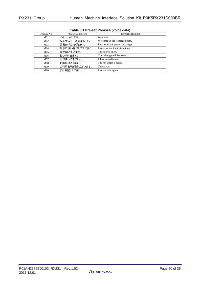
Table 5.1 Pre-set Phrases (voice data)
Display No. Phrase (Japanese) Remarks (English)
M01 いらっしゃいませ。 Welcome.
M02 ルネサスブースにようこそ。 Welcome to the Renesas booth.
M03 係員を呼んでください。 Please call the person in charge.
M04 指示に従い操作してください。 Please follow the instructions.
M05 扉が開いています。 The door is open.
M06 おつりが出ます。 Your change will be issued.
M07 雨が降ってきました。 It has started to rain.
M08 お湯が沸きました。 The hot water is ready.
M09 ご利用ありがとうございます。 Thank you.
M10 またお越しください。 Please come again.

RX231 Group Human Machine Interface Solution Kit R0K5RX231D000BR
R01AN2586EJ0102_RX231 Rev.1.02 Page 21 of 35
2016.12.01
Figure 5.8 Demo 2: SOUND “REC: record & playback voice” (record) in Normal Mode
(1) Select Demo 2 (SOUND)
■REC: voice record & playback(2) Select record/playback [Record] *Refer to next page for Select record/playback [Playback].
SOUND TALKREC
SOUND Voice1 Select Voice2
SOUND RecStartRec NoData
Three seconds after power is turned on:・Select the screen to the left by sliding to right [>>>] or left [<<<].・Select REC with ▲/▼, then press [ENT].
TALK: plays back pre-set audio data (audio data is stored in MCU internal ROM.REC: Records and plays back voice (audio data is stored in flash memory)
(3) Select audio data
・Use ▲/▼ to select Voice1/Voice2.・Press [ENT[ to start recording.
(4) Now recording.
・Remaining recording time (sec) is displayed at upper right while recording.・Recording time for each data is fixed at 10 seconds.・Press SW1 to cancel while recording.Data will not be saved, and display returns to “(3) Select audio data”.
・Use ▲/▼ to select [RecStart].If there is not audio data, the only selectable item is [RecStart].・Press [ENT] to bring up the “(3) Select audio data” display.・ Press [BACK] to return to “(1) Select Demo 2 (SOUND).”
SOUND 10Recording
SOUND RecStartRec Playback
(5) After recording is complete.
When recording is complete, display returns to “(2) Select record/playback.”
SOUND RecStartRec Playback

RX231 Group Human Machine Interface Solution Kit R0K5RX231D000BR
R01AN2586EJ0102_RX231 Rev.1.02 Page 22 of 35
2016.12.01
Figure 5.9 Demo 2: SOUND “REC: record & playback voice” (playback) in Normal Mode
(1) Select Demo 2 (SOUND)
■REC: voice record & playback(2) Select record/playback [Playback].
SOUND TALKREC
SOUND Voice1 Select Voice2
SOUND RecStartRec NoData
Three seconds after power is turned on:・Select the screen to the left by sliding right [>>>] or left [<<<].・Select REC with ▲/▼, then press [ENT].
TALK: plays back pre-set audio data (audio data is stored in MCU internal ROM.REC: Records and plays back voice (audio data is stored in flash memory)
(3) Select playback data.
・Use ▲/▼ to select Voice1 or Voice2.Data that has not been recorded cannot be selected.
・ Press [ENT] to begin playback.
(4) Now playing.
・Remaining playback time (sec) is displayed at upper right while recording.・Playback time for each data is fixed at 10 seconds.・ Press SW1 to stop during playback.
・Use ▲/▼ to select “Playback”.Playback cannot be selected If there is no recorded.・Press [ENT] to bring up the “(3) Select audio data” display.・ Press [BACK] to return to “(1) Select Demo 2 (SOUND).”
SOUND Rec Playing
SOUND RecStartRec Playback
(5) After playback is complete.
When playback is done, display returns to “(2) Select record/playback.”・Refer to “(2) Select record/playback” above.SOUND RecStart
Rec Playback
*Playback cannot be selected if there is no recorded data.

RX231 Group Human Machine Interface Solution Kit R0K5RX231D000BR
R01AN2586EJ0102_RX231 Rev.1.02 Page 23 of 35
2016.12.01
5.2.1.3. Normal Mode: OTHER (Time setting)
Figure 5.10 OTHER (time setting) in Normal Mode
(1) Select OTHER.
(2 Set “hour.”
OTHER TimeVer
OTHER 12:00Time setting
Three seconds after power is turned on:・Select the screen to the left by sliding right [>>>] or left [<<<].・Select TIME with ▲/▼, then press [ENT].
Time: Sets clock, based on a 24-hour clockVer: Displays versionTimeout: Selects timeout period (1 min/5 sec) for “Demo 1 (ECO). Walk: PedometerTouch: Touch key adjustments
(3 ) Set “minutes.”
・ Set the minutes (blinking) with ▲/▼.・ Press [ENT] to fix the minutes and complete the setting.・ The clock will start running from 0 seconds at the set time.・ Press BACK to return to “(1) Select OTHER.”
(4) Time setting is complete.
・After the setting is completed, the display returns to the initial “(1) OTHER” screen.
・Set the hour (blinking) with ▲/▼.・ Press [ENT] to fix the hour, then continue on to set the minutes.
OTHER TimeVer
OTHER 12:00Time setting

RX231 Group Human Machine Interface Solution Kit R0K5RX231D000BR
R01AN2586EJ0102_RX231 Rev.1.02 Page 24 of 35
2016.12.01
5.2.1.4. Normal Mode: OTHER (Version Display)
Figure 5.11 Normal Mode: OTHER (Version Display)
(1) Select OTHER.
(2) Select “VER.”
OTHER TimeVer
OTHER Ver 1.00Version
Three seconds after power is turned on:・Select the screen to the left by sliding right [>>>] or left [<<<].
(3) Display ”Version.”
・Displays version. ・Pressing [ENT] does not change anything.
(4) “VER” display is completed.
・Press [BACK] to return to “(2)” screen.
OTHER VerTimeout
・Select VER with ▲/▼, then press ENT.Time: Sets the clock, based on a 24-hour clock.Ver: Displays versionTimeout: Selects timeout period (1 min./5 sec) for Demo 1 (ECO) Walk: PedometerTouch: Cap touch sensitivity adjustments
OTHER VerTimeout

RX231 Group Human Machine Interface Solution Kit R0K5RX231D000BR
R01AN2586EJ0102_RX231 Rev.1.02 Page 25 of 35
2016.12.01
5.2.1.5. Normal Mode: OTHER (Timeout period selection)
Figure 5.12 OTHER (Timeout period selection) in Normal Mode
(1) Select OTHER
(2) Select TIMEOUT
OTHER TimeVer
OTHER 1minTimeout 5sec
Three seconds after power is turned on:・Select the screen to the left by sliding right [>>>] or left [<<<].
(3) Select TIMEOUT period.
・Select TIMEOUT with ▲/▼・Press [ENT].
(4) TIMEOUT completed.
・Returns to “(2)” screen.
OTHER TimeoutWalk
・Select TIMEOUT with ▲/▼, then press [ENT].Time: Sets clock, based on a 24-hour clock.Ver: Displays versionTimeout: Selects time for Demo 1 (ECO) Timeout (1 min./5 sec)Walk: PedometerTouch: Cap touch sensitivity adjustments
OTHER TimeoutWalk

RX231 Group Human Machine Interface Solution Kit R0K5RX231D000BR
R01AN2586EJ0102_RX231 Rev.1.02 Page 26 of 35
2016.12.01
5.2.1.6. Normal Mode: OTHER (Pedometer)
Figure 5.13 OTHER (Pedometer) in Normal Mode
(1) Select OTHER
(2) Select ”WALK.”
OTHER TimeVer
OTHER todayWalk xxxxxCnt
Three seconds after power is turned on:・Select the screen to the left by sliding right [>>>] or left [<<<].
(3) Pedometer starts operating.
Initiates pedometer operations.・”xxxxx” indicates number of steps (max. 65535).・ Display previous 5 days of recorded data using ▲ /▼.
today, -1day, -2day, -3day, -4day, -5day・[ENT] is disabled.・Press BACK to stop pedometer.
(4) ”WALK” operations ended.
・Returns to “(2)” screen.
OTHER WalkTouch
・Select WALK with ▲/ ▼, then press [ENT].Time: Sets clock, based on a 24-hour clockVer: Displays versionTimeout: Selects timeout period (1 min/5 sec) for Demo 1 (ECO). Walk: PedometerTouch: Cap touch sensitivity adjustments
OTHER WalkTouch

RX231 Group Human Machine Interface Solution Kit R0K5RX231D000BR
R01AN2586EJ0102_RX231 Rev.1.02 Page 27 of 35
2016.12.01
5.2.1.7. Normal Mode: OTHER (Cap Touch Adjustments)
Figure 5.14 OTHER (cap touch adjustments) in Normal Mode
Note 1. Refer to the Renesas website for details on Workbench6(Integrated Development Environment for Renesas
Capacitive Touch). http://renesas.com/applications/key_technology/human_interface/touch_sensor_system_2gen/child/technology_child.jsp
(1) Select OTHER.
(2) Select ”TOUCH.”
OTHER TimeVer
OTHERTouch Adj.
Three seconds after power is turned on:・Select the screen to the left by sliding right [>>>] or left [<<<].
(3) Touch key sensory adjustment state
In this state, cap touch elements cannot be used to move to another function.Cap touch detection is triggered by key sound.*If no key sound is emitted, nothing is detected.Cap touch sensitivity adjustments are made with Capacitive Touch IDE Workbench 6 (Note 1).
・Press SW1 to finish adjustments.
(4) ”TOUCH” adjustments completed.
・Returns to “(2)” screen.
OTHER TouchTime
・Select TOUCH with ▲/ ▼, then press ENT.Time: Sets clock, based on a 24-hour clock.Ver: Displays versionTimeout: Selects time for Demo 1 (ECO) Timeout (1 min./5 sec)Walk: PedometerTouch: Cap touch sensitivity adjustments
OTHER TouchTime

RX231 Group Human Machine Interface Solution Kit R0K5RX231D000BR
R01AN2586EJ0102_RX231 Rev.1.02 Page 28 of 35
2016.12.01
5.2.1.8. Preparations of using Workbench6 (Connection with PC)
Refer to the Renesas website for details on Workbench6(Integrated Development Environment for Renesas Capacitive
Touch). http://renesas.com/applications/key_technology/human_interface/touch_sensor_system_2gen/child/technology_child.jsp
Figure 5.15 Connection of USB cable with PC
PC
■USB cable connectionConnect the Kit board and host PC with a USB cable . The USB-microB connector is located the back side of the board. A power supply is chosen in SW1. (USB or DC-Jack)
USB-microBBack side of board

RX231 Group Human Machine Interface Solution Kit R0K5RX231D000BR
R01AN2586EJ0102_RX231 Rev.1.02 Page 29 of 35
2016.12.01
5.2.1.9. Preparations of using Workbench6 (USB driver Installation)
Figure 5.16 USB Driver Installation
1. Follow the procedure below when Windows asks for driver installation. (This example uses Windows 7.)
Installation method specification dialogue.
2. Specify “R0K5RX231D000BR_20150916.inf” location.
3. A warning dialogue will appear; ignore and press “Continue”.
4. When completion dialogue appears, driver installation is complete.
(Designate a place of "R0K5RX231D000BR_20150916.inf")

RX231 Group Human Machine Interface Solution Kit R0K5RX231D000BR
R01AN2586EJ0102_RX231 Rev.1.02 Page 30 of 35
2016.12.01
5.2.2. Storage Mode Operations
This section describes how to use the HMI Solution Kit in storage mode. For instructions on how to start up the board
in storage mode, Refer to section 5.1.2.
Figure 5.17 Storage Mode Operations
(1) Startup in storage mode
Set SW4 to the following and then supply power to the board.
StorageRead Only
(2) LCD display during storage mode
The board is recognized by the PC as a USB memory.
・This memory can’t write and erase from PC.
・The board’s on-board serial flash is used as memory.
・Recorded audio data is stored in the flash memory (Note 1).
・LED1 (green) blinks when a file is accessed.
*Note 1. The extension for audio data is “dat”.
Audio data is to convert it to a wav file by Renesas ADPCM change tool, and it can be played on the PC.
Turn on power while pressing SW1 down. Release SW1 after the screen in (2) below appears.
*For USB bus-power, connect the USB cable while pressing SW1 down.
USB-microB
Back side of board
PC
SW1
Back side of board
SW4 location
*The setting of the lowest SW4 bit is not related to the startup mode.
■Storage mode
Set the upper 3 bits of SW4 to OFF.SW4
OFF ON

RX231 Group Human Machine Interface Solution Kit R0K5RX231D000BR
R01AN2586EJ0102_RX231 Rev.1.02 Page 31 of 35
2016.12.01
5.2.3. USB Boot Mode Operations
This section describes how to use the HMI Solution Kit in USB boot mode. For instructions on how to start up the
board, Refer to section 5.1.2.
USB boot mode is an MCU function that enables a program to be downloaded via a USB cable. The Kit board is equipped with a
switch for starting up operations in USB boot mode. You will need a Renesas FLASH Programmer to use this mode. Visit the
Renesas website for more details.
http://www.renesas.com/products/tools/flash_prom_programming/rfp/index.jsp
Figure 5.18 Operations in USB Boot Mode
(1) Startup in USB boot modeSet SW4 as shown below and then supply power to the board.
USB-microBBack side of board
PC
Back of board
SW4 location
■USB boot modeSet the upper 3 bits of SW4 to ON, then supply power.
SW4OFF ON
*The setting of the lowest SW4 bit is not related to the startup mode.
(2) USB cable connectionConnect the Kit board and host PC with a USB cable . The USB-microB connector is located the back side of the board.A power supply is chosen in SW1. (USB or DC-Jack)

RX231 Group Human Machine Interface Solution Kit R0K5RX231D000BR
R01AN2586EJ0102_RX231 Rev.1.02 Page 32 of 35
2016.12.01
5.3. E1 Connection
Connect the E1 Emulator to rewrite or debug RX231 programs.
(1) Make sure the board’s power is turned off.
(2) Connect the E1 cable to CN4 on the board.
Confirm the location of the polarizing key first to avoid mis-insertion.
Refer to the usage manuals included with E1 and the development environment for instructions on how to use E1.
When supplying power from E1, turn off the board’s power supply (DC jack or USB). The safest way is to cut off
power input from both the DC jack and USB bus is by removing JP1.
Figure 5.19 E1 Connection Diagram
Insert the E1 cable in accordance with the polarizing key to prevent mis-insertion.
Back side of board

RX231 Group Human Machine Interface Solution Kit R0K5RX231D000BR
R01AN2586EJ0102_RX231 Rev.1.02 Page 33 of 35
2016.12.01
6. Notes when using J3 (monaural jack)
The common electric potential of the voice output (J3) of this board is 1.6V.
When using J3, please don't connect the speaker which "a common electrode of J3" and "GND of this board" is shorted.
Otherwise, this board will break down by an over-current.
When supplying speaker with amplifier and this board from an identical power supply,please don’t connect the speaker with amplifier to J3.
Speaker with amplifier Speaker without amplifier
Back side of board
J2
NG
J3
OKOK
Power supply from USB
Common electrodeJ2: GND
Common electrodeJ3: 1.6V
Figure 6.1 Use example of J3

RX231 Group Human Machine Interface Solution Kit R0K5RX231D000BR
R01AN2586EJ0102_RX231 Rev.1.02 Page 34 of 35
2016.12.01
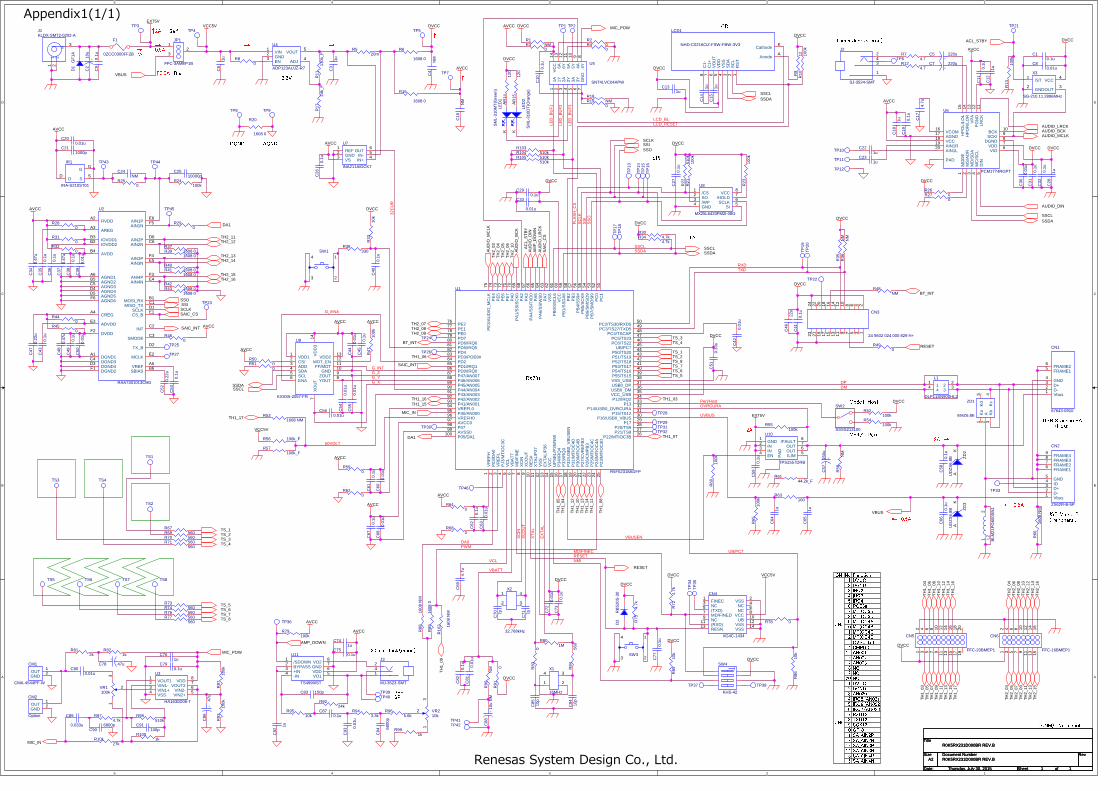
7. Circuit Diagram
Refer to appendix 1.
8. Component Layout Diagram
Refer to appendix 2.
9. Parts List
Refer to appendix 3.

RX231 Group Human Machine Interface Solution Kit R0K5RX231D000BR
R01AN2586EJ0102_RX231 Rev.1.02 Page 35 of 35
2016.12.01
Website and Support
Renesas Electronics Website
http://www.renesas.com/
USB Device Website
http://www.renesas.com/applications/key_technology/connectivity/usb/index.jsp
Inquiries
http://www.renesas.com/contact/
All trademarks and registered trademarks are the property of their respective owners.
5
5
4
4
3
3
2
2
1
1
D D
C C
B B
A A
2A
2A →
→→
→
←
←←
←
0.5A←
←←
←
0.5A
3.5mm Jack(stereo)
AGNDDGND
※(NM) : No mount
USB Micro-B
(Peripheral)
USB Standard-A
(Host)
↑
↑↑
↑
Renesas System Design Co., Ltd.
SP+
SP-
0.5A
↑
↑↑
↑
↑
↑↑
↑
3.2V
→
→→
→→
→→
→
LCD
SPI
10
16
20
11
12
13
14
15
17
18
19
3
4
5
6
7
8
9
2
1
CN5
No.
DGND
DVCC
IRQ2
IRQ3
IRQ4
POE8#
MTIOC3B
MTIOC3D
MTIOC4A
MTIOC4B
MTIOC4C
MTIOC4D
CVREFB3
NC
CMPB3
AN001
AN002
NC
NC
DVCC
DGND
IRQ7/AN023
IRQ6/AN022
IRQ5/AN021
AN020
RXD12
TXD12
SCK12
SA_AIN2P
SA_AIN2N
SA_AIN3P
SA_AIN3N
SA_AIN4P
SA_AIN4N
FunctionCN
GPIO10
16
11
12
13
14
15
3
4
5
6
7
8
9
2
1
CN6
AN003
I2C
2A
2A
→
→→
→
0.5A→
→→
→
↑
↑↑
↑
Mode1/Host
Mode2/Peri
RX231
Self
Bus
3.5mm Jack(mono)
Appendix1(1/1)
VBATT
SS
IS
SO
SC
LK
LED
_BU
F2
LED
_BU
F1
TXDRXD
PWMDA0
XC
INX
CO
UT
LED
_BU
F3
XT
AL
VCL
MD/FINECRESETNMI
FLA
SH
_CS
UB/PC7
G_X
EX
TA
L
UVBUS
OVRCURA
DM
VBUSEN
Peri/Host
32C
UR
LCD_BLLCD_RESET
G_YG_ZG_INT
G_ENA
50VOLT
SSCLSSDA
AUDIO_LRCK
TH
1_03
TH
1_05
SA
IC_C
S
TH
1_06
TH
1_04
AUDIO_BCK
AUDIO_DIN
AUDIO_MCLK
SSDASSCL
AU
DIO
_LR
CK
AM
P_D
OW
NA
UD
IO_D
IN
AU
DIO
_BC
K
AU
DIO
_MC
LK
TH
2_04
TH
2_03
TH
2_06
TH
2_05
TH2_07
TH
2_10
TH2_09TH2_08
TH1_06
TH1_15TH1_16
SSCL
TH
1_12
TH
1_10
TH
1_13
TH
1_14
TH
1_11
TH
1_08
TH
1_07
TH
1_09
TH
1_13
TH
1_11
TS_3TS_2TS_1
TS_4
VBUS
SAIC_INT
TS_8TS_7TS_6TS_5
AMP_DOWN
TH
1_05
TH
1_04
TH1_07
TH
1_08
TH
1_12
TH
1_10
TH
1_14
TH
1_16
TH
2_03
TH
2_07
TH
2_05
TH
2_11
TH
2_09
TH
2_13
TH
2_15
TH
2_04
TH
2_08
TH
2_06
TH
2_10
TH
2_16
TH
2_12
TH1_03
RESET
TS_5
TS_7TS_6
TS_2TS_8
TS_4
TS_1
TS_3
DA1
SCLK
SSOSSI
SSDASSCL
SSCLSSDA
BT_INT
BT_INT
TH
2_14
RESET
MIC_POW
MIC_POW
MIC_IN
MIC_IN
SSDA
TH
1_15
TH1_17
TH
1_17
SAIC_CS
SSO
SCLKSSI
SAIC_INT
TH2_11
TH2_13
TH2_12
TH2_15
TH2_14
TH2_16
DA1
VBUS
AC
L_S
TB
Y
ACL_STBY
TH
1_09
DVCC
AVCC
DVCC
DVCC
AVCC
DVCC
DVCCDVCC
AVCC
DVCC
VCC5VDVCC
AVCC
AVCC
AVCC
AVCC
DVCC
DVCC
DVCC
DVCC
EXT5V
VCC5V
AVCC
DVCC
DVCC
AVCC
DVCC
AVCC
DVCC
DVCC
DVCC
DVCC
VCC5V
DVCC
AVCC
DVCCAVCC
AVCC
AVCC
AVCC
AVCC
DVCCDVCC
EXT5V
DVCC
Title
Size Document Number Rev
Date: Sheet of
R0K5RX231D000BR REV.B
R0K5RX231D000BR REV.B
A2
1 1Thursday, July 30, 2015
Title
Size Document Number Rev
Date: Sheet of
R0K5RX231D000BR REV.B
R0K5RX231D000BR REV.B
A2
1 1Thursday, July 30, 2015
Title
Size Document Number Rev
Date: Sheet of
R0K5RX231D000BR REV.B
R0K5RX231D000BR REV.B
A2
1 1Thursday, July 30, 2015
TP7
+
C5 220u
LED
2S
ML-
310D
T(O
rang
e)
AK
R33
10k
R52100k
R40
C52
0.22
u
R65
100k
R14
120
C870.1u
TP
35
U2
RAA7301013CBG
DGND1A1
RVDDA2
AREGA3
CREGA4
VREFA5
AGND1A6
MOSI_RXB1
IOVDD2B2 IOVDD1B3
AVDDB4
AGND2B5
SBIASB6
MISO_TXC1
INTC2
SMODEC3
DGND3C4
AGND3C5
AIN2NC6
SCLKD1
TX_BD2
DGND4D3
AGND4D4
AGND5D5
AIN2PD6
CS_BE1
MCLKE2
ADVDDE3
AIN4NE4
AIN3NE5
AIN1PE6
DGND2F1
DVDDF2
ANI4PF3
AIN3PF4
AIN1NF5
AGND6F6
C19
0.1u
R23
100k
R9510k
MX25L6433FM2I-08G
U8
/CS1
SO2
/WP3
GND4
SI5SCLK6/HOLD7VCC8
R79100k
TS6
U9
KXSS5-2057-FR
VDD11
CS/2
ADD3
SCL5 SDA4
ENA6
XO
UT
7
YOUT8ZOUT9GND10FF/MOT11MOT_EN12VDD213V
DD
314
C59
0.1u
TP40
C38
0.1u
C53
0.1u
C51
0.33
u
C48
0.47
u
C6
1u
C68
0.01
u
R22
510k
R965.6k
R15
120
R90
NM
R91
0
R280
R76560
CM2
Option
GND2OUT1
C17
4.7u
C34
0.47
u
C46
22u
TS1
R60
100k
SW3
14
23
C47
0.22
u
R10
2 1608
NM
LED
1S
ML-
310M
T(G
reen
)
AK
R54100k
C67
0.1u
R88
1608
NM
F1
0ZCC0300FF2B
TP12
+
C57
150u
IR1
IRA-S210ST01
DD
GG
SS
R260
C741u
VR210k
13
2
C40
0.1u
TS4
C37
0.47
u
C211000p
C14
1u
J2
SJ-3524-SMT
42
1
3
R11
130k
_F
VR1100k
3
2
1
R105510k
R77560
ADP123AUJZ-R7
U4
VIN1
GND2
EN3
ADJ4
VOUT5
INA211AIDCKT
U7
REF1
GND2
VS3
IN+4IN-5OUT6
R74560
SG-210 11.2896MHz
X3
GND2
VCC4
OUT3
/ST1
C750.1u
TP32
J3
MJ-3523-SMT
142
TP
19
R490
U1
R5F52318ADFP
VR
EF
H1
P03
/DA
02
VR
EF
L3
PJ3
/MT
IOC
3C4
VC
L5
VB
AT
T6
MD
/FIN
E7
XC
IN8
XC
OU
T9
RE
S#
10
XT
AL/
P37
11
VS
S12
EX
TA
L/P
3613
VC
C14
UP
SE
L/P
35/N
MI
15
P34
/IRQ
416
P33
/IRQ
317
P32
/US
B0_
VB
US
EN
18
P31
/MT
IOC
4D19
P30
/MT
IOC
4B20
P27
/CV
RE
FB
321
P26
/CM
PB
322
P25
/MT
IOC
4C23
P24
/MT
IOC
4A24
P23
/MT
IOC
3D25
P22/MTIOC3B26P21/TS827P20/TS928P1729P16/USB0_VBUS30P15/TS1231P14/USB0_OVRCURA32P1333P12/IRQ234VCC_USB35USB0_DM36USB0_DP37VSS_USB38P55/TS1539P54/TS1640P53/TS1741P52/TS1842P51/TS1943P50/TS2044UB/PC745PC6/TS2246PC5/TS2347PC4/TSCAP48PC3/TS27/TXD549PC2/TS30/RXD550
PC
151
PC
052
PB
7/S
MO
SI9
53P
B6/
SM
ISO
954
PB
5/S
CK
955
PB
4/S
S9#
56P
B3
57P
B2
58P
B1/
SS
DA
659
VC
C60
PB
0/S
SC
L661
VS
S62
PA
763
PA
6/S
SIW
S0
64P
A5
65P
A4/
SS
ITX
D0
66P
A3
67P
A2
68P
A1/
SS
ISC
K0
69P
A0
70P
E7
71P
E6
72P
E5
73P
E4
74P
E3/
AU
DIO
_MC
LK75
PE276
PE177
PE078
PD779
PD6/IRQ680
PD5/IRQ581
PD482
PD3/POE8#83
PD284
PD1/IRQ185
PD0/IRQ086
P47/AN00787
P46/AN00688
P45/AN00589
P44/AN00490
P43/AN00391
P42/AN00292
P41/AN00193
VREFL094
P40/AN00095
VREFH096
AVCC097
P0798
AVSS099
P05/DA1100
C36
0.1u
TP27
SN74LVC04APW
U5
1A1
1Y2
2A3
2Y4
3A5
3Y6
GN
D7
4Y8
4A9
5Y10
5A11
6Y12
6A13
VC
C14
C10
0.1u
R812k
R10
100k
R87
100k
C61
0.1u
C16
NM
CN1
67643-0910
Vbus1 D-2 D+3 GND4
FRAME15 FRAME26
R10127k
R89
1608
0
R371608 0
R9224k
C83 150p
R640
C39
0.01
u
C63
0.01
u
R531608 NM
R1001k
R86
10k
C221u
U6
PCM1774RGPT
MO
DE
1
MS
/AD
R2
MD
/SD
A3
MC
/SC
L4
DIN
5
VIO6VDD7DGND8SCKI9BCK10
LRC
K11
PG
ND
12V
PA
13H
PO
R/L
OR
14H
PO
L/LO
L15
VCOM16
AGND17
VCC18
AIN1R19
AIN1L20
PAD
R85
10k
R48NM
R801M
TP
17
R270
R38330
C32
0.1u
C50
0.01
u
R590
TP44
TS5
C15
1u
R17
24k_
F
TP10
C77
0.1u
CN3
24 5602 024 000 829 H+
12
34
568
910
1112
1314
1516
1718
1920
2122
2324
C94
6800
p
TP
16
TP37
C30
0.01
u
C58
0.1u
+
C86
47u
R344.7k
C131u
C906800p
R16
1608 0
R250
R1NM
C800.01u
X2
32.768kHz
41
2 3
TP39
TS2
R460
TP
15
C72
0.01
u
C11
0.1u
R440
D2
RB
520S
-30
HA1630D06-T
U3
VOUT11
VIN1-2
VIN1+3
VSS4
VIN2+5VIN2-6VOUT27VDD8
C55
0.01
u
R18NM
TP41
TPS2557DRB
U10
GND1
IN2
IN3
EN4
ILIM5OUT6OUT7/FAULT8
PA
D
R9
12
TP28
R71560
TP
34
C49
0.1u
TP11
R401608 0
TP21
R13
100k
R56 100k_F
C231u
SW114
23
C69
4.7u
TP25
R47
100k
R80
C24NM
C790.1u
C26
0.1u
TP5
R310
C89
0.033u
R36
NM
R70560
TP4
C91100p
C71 7p
R450
R20
C2510000p
C44
0.01
u
+
C78 47u
R93
100k
TP38
R69560
R73560
C200.01u
R58
NM
R30
TP
18
R421608 0
JP1
FFC-3AMEP1B
12
3
TP22
CM1
CMA-4544PF-W
GND2OUT1
TP43
TP31
R391608 0
R6
1608 0
R520m
R67560
TS7
C35
0.1u
R84
560
R104510k
R6144.2k_F
C64
1u
R991k
TP8
C81
0.01
u
TP9
R821k
C43
0.1u
TP33TP46
C31
0.1u
C41
0.1u
R680
C73
0.1u
C85 10
p
SW4
KHS-42
R431608 0
C65
1u
C82
0.1u
L2 BLM
21P
G60
0SN
1
12
TS8
C4
NM
C3
1u
R63100
C66
0.1u
C93
0.01
uC
450.
1u
R55100k
R411608 0
R943.3k
SW2
SSSS213100
R24100k
CN6
FFC-16BMEP112
34
56
78
910
1112
1314
1516
C80.01u
R66
1608
NM
R620
C84 10
p
R75
4.7k
R78 0
EMZ6.8E
ZD1
A2
Kc
4
Kd
5
Kb
3
Ka
1
C290.1u
X1
16MHz
21
4 3
C10.1u
TP24
+
C7 220u
J1KLDX-SMT2-0202-A
11
22
33
TP36
C42
0.01
u
C60
0.01
u
R320
R290
C761u
ZD
2
UD
ZS
6.8B
AK
D1
GF
1A
C33
0.01u
R510
TP29
R304.7k
R74.7
TS3
R35
NM
ZD
3
UD
ZS
6.8B
AK
TS4990IST
U11
/SDOWN1
BYPASS2
+IN3
-IN4
VO15VDD6GND7VO28
R20
1608 0
R974.7k
TP26
R21
100k
R124.7C
90.
1u
R103510k
C54
0.01
u
CN4
XG4C-1434
VSS2
NC4
NC6
VCC8
UB10
VSS12
VSS14
FINEC1
NC3
(TXD)5
MD/FINED7
NC9
(RXD)11
RESN13
+
C88
10u
NM
R57100k_F
LCD1
NHD-C0216CiZ-FSW-FBW-3V3
RS
T1
SC
L2
SD
A3
VS
S4
VD
D5
VO
UT
6C
1+7
C1-
8
AnodeA
CathodeK
TP
20
TP
14
TP45
TP23
R72
4.7k
C12
1u
CN2
ZX62R-B-5P
Vbus1 D-2 D+3
GND5
FRAME16
ID4
FRAME27 FRAME38 FRAME49
R98510k
TP1
C27
0.1u
C62
0.1u
CN5
FFC-20BMEP112
34
56
78
910
1112
1314
1516
1718
1920
R500
C70 7p
TP30
TP3
R83
0
C92
1u
C28
1uTP
13
R190
C18
1u
TP6
TP42
TP2
C560.01u
L1
DLP11SN900HL2
11
22
44
33
+
C2
10u
DP
7

Appendix2(1/1)

Appendix3(1/4) Renesas System Design Co., Ltd.
Type Symbol on Board Product Number (Specfication) Manufacture Mount/Unmount1 Microphone CM1 CMA-4544PF-W CUI Mount 12 USB Standard A CN1 67643-0910 Molex Mount 13 USB Micro B CN2 ZX62R-B-5P Hirose Mount 1
4 Connector CN324 5602 024 000 829 H+24 5602 624 000 829 H+
KYOCERAConnetor
Mount 1
5 Connector CN4 XG4C-1434 Omron Mount 1
6 Ceramic Capacitor
C1,C9,C10,C11,C19,C26,C27,C29,C31,C32,C35,C36,C38,C40,C41,C43,C45,C49,C53,C58,C59,C61,C62,C66,C67,C73,C75,C77,C79,C82,C87
GRM155R71C104KA88D Murata Mount 31 0.1u
7 Electrolytic Capcitor C2 EMVA250ADA100MD55G NIPPON CHEMI-CON Mount 1 10u,25V
8 Ceramic CapacitorC3,C6,C12,C13,C14,C15,C18,C22,C23,C28,C64,C65,C74,C76,C92
GRM155R61A105KE15D Murata Mount 15 1u
9 Electrolytic Capcitor C5,C7 EMVA100ADA221MF80G NIPPON CHEMI-CON Mount 2 220u,10V
10 Ceramic Capacitor
C8,C20,C30,C33,C39,C42,C44,C50,C54,C55,C56,C60,C63,C68,C72,C80,C81,C93
GRM155B11E103KA01D Murata Mount 18 0.01u
11 Ceramic Capacitor C17,C69 GRM155R60J475ME47D Murata Mount 2 4.7u12 Ceramic Capacitor C21 GRM1555C1H102JA01D Murata Mount 1 1000p13 Ceramic Capacitor C25 GRM155B11E103KA01D Murata Mount 1 10000p14 Ceramic Capacitor C34,C37,C48 GRM155R61A474KE15D Murata Mount 3 0.47u15 Ceramic Capacitor C46 C2012X5R1A226M125AB TDK Mount 1 22u16 Ceramic Capacitor C47,C52 GRM155R71C224KA12D Murata Mount 2 0.22u17 Ceramic Capacitor C51 GRM155R61A334KE15D Murata Mount 1 0.33u18 Electrolytic Capcitor C57 EMVA160ADA151MF80G NIPPON CHEMI-CON Mount 1 150u,16V19 Ceramic Capacitor C70,C71 GRM1555C1H7R0BA01D Murata Mount 2 7p20 Electrolytic Capcitor C78,C86 EMVA6R3ADA470MD55G NIPPON CHEMI-CON Mount 2 47u,6.3V21 Ceramic Capacitor C83 GRM1555C1H151JA01D Murata Mount 1 150p22 Ceramic Capacitor C84,C85 GRM1555C1H100RA01D Murata Mount 2 10p23 Ceramic Capacitor C89 GRM155B31E333KA87D Murata Mount 1 0.033u24 Ceramic Capacitor C90,C94 GRM155R11E682KA01 Murata Mount 2 6800p25 Ceramic Capacitor C91 GRM1552C1H101JZ01D Murata Mount 1 100p
- RemarksNoComponent Name Component Specification
Qty/set
Parts List of R0K5RX231D000BR Board

Appendix3(2/4) Renesas System Design Co., Ltd.
Type Symbol on Board Product Number (Specfication) Manufacture Mount/Unmount- RemarksNo
Component Name Component SpecificationQty/set
26 Diode D1 GF1A-E3/67A Vishay Mount 127 Diode D2 RB520S-30 Rohm Mount 128 Polyswitch F1 0ZCC0300FF2B Bel Fuse Mount 129 Pyroelectric infrared sensor IR1 IRA-S210ST01 Murata Mount 130 Jumper JP1 FFC-3AMEP1B HTK Mount 131 DC Jack J1 KLDX-SMT2-0202-ATR Kycon Mount 132 AUDIO JACK J2 SJ-3524-SMT CUI Mount 1 3.5mm STEREO 33 AUDIO JACK J3 MJ-3523-SMT CUI Mount 1 3.5mm MONO34 LCDモジュール LCD1 NHD-C0216CiZ-FSW-FBW-3V3 NewHaven Display Mount 135 LED LED1 SML-310MT Rohm Mount 1 Green36 LED LED2 SML-310DT Rohm Mount 1 Orange
37 Chip Resistor
R2,R3,R4,R8,R19,R25,R26,R27,R28,R29,R31,R32,R44,R45,R46,R49,R50,R51,R59,R62,R64,R68,R78,R83,R91
MCR01MRTJ000 Rohm Mount 25 1005 0
38 Shunt Resistor R5 UCR03EWPFSR020 Rohm Mount 1 20mΩ
39 Chip ResistorR6,R16,R20,R37,R39,R40,R41,R42,R43,R89
MCR03MRTJ000 Rohm Mount 10 1608 0
40 Chip Resistor R7,R12 MCR01MRTJ4R7 Rohm Mount 2 4.741 Chip Resistor R9 MCR01MRTJ120 Rohm Mount 1 12
42 Chip ResistorR10,R13,R21,R23,R24,R47,R52,R54,R55,R60,R65,R79,R87,R93
MCR01MRTJ104 Rohm Mount 14 100k
43 Chip Resistor R11 MCR01MRTF1303 Rohm Mount 1 130k_F44 Chip Resistor R14,R15 MCR01MRTF1200 Rohm Mount 2 12045 Chip Resistor R17 MCR01MRTF2402 Rohm Mount 1 24k_F46 Chip Resistor R22,R98,R103,R104,R105 MCR01MRTJ514 Rohm Mount 5 510k47 Chip Resistor R30,R34,R72,R75,R97 MCR01MRTJ472 Rohm Mount 5 4.7k48 Chip Resistor R33,R85,R86,R95 MCR01MRTJ103 Rohm Mount 4 10k49 Chip Resistor R38 MCR01MRTJ331 Rohm Mount 1 33050 Chip Resistor R56,R57 MCR01MRTF1003 Rohm Mount 2 100k_F51 Chip Resistor R61 ERJ-2RKF44422X Panasonic Mount 1 44.2k_F52 Chip Resistor R63 MCR01MRTJ101 Rohm Mount 1 100
53 Chip ResistorR67,R69,R70,R71,R73,R74,R76,R77,R84
MCR01MRTJ561 Rohm Mount 9 560
54 Chip Resistor R80 MCR01MRTJ105 Rohm Mount 1 1M55 Chip Resistor R81 MCR01MRTJ202 Rohm Mount 1 2k56 Chip Resistor R82,R99,R100 MCR01MRTJ102 Rohm Mount 3 1k57 Chip Resistor R92 MCR01MRTJ243 Rohm Mount 1 24k58 Chip Resistor R94 MCR01MRTJ332 Rohm Mount 1 3.3k

Appendix3(3/4) Renesas System Design Co., Ltd.
Type Symbol on Board Product Number (Specfication) Manufacture Mount/Unmount- RemarksNo
Component Name Component SpecificationQty/set
59 Chip Resistor R96 MCR01MRTJ562 Rohm Mount 1 5.6k60 Chip Resistor R101 MCR01MRTJ273 Rohm Mount 1 27k61 Tactile Switch SW1,SW3 B3SN-3012 Omron Mount 262 Slide Switch SW2 SSSS213100 ALPS Mount 163 DIP Switch SW4 KHS-42 Otax Mount 164 RX231 MCU U1 R5F52318ADFP Renesas Mount 1
65 Smart Analog IC U2RAA7301013CBGRAA7301014CBG
Renesas Mount 1
66 Op Amp U3 HA1630D06-T Renesas Mount 167 Linear Regulator U4 ADP123AUJZ-R7 ADI Mount 168 Logic IC U5 SN74LVC04APW TI Mount 169 Audio DAC U6 PCM1774RGPT TI Mount 170 Current-Shunt Monitor U7 INA211AIDCKT TI Mount 171 Flash Memory U8 MX25L6433FM2I-08G Macronix Mount 172 Accelerometer U9 KXSS5-2057-FR Kionix Mount 173 Current Switch IC U10 TPS2557DRB TI Mount 174 Audio Power Amp U11 TS4990IST STMicro Mount 175 Variable Resistor VR1 3352T-1-104LF Bourns Mount 1 100k76 Variable Resistor VR2 3352T-1-103LF Bourns Mount 1 10k77 Crystal Unit X1 FA-238 16MHz EPSON Mount 1 16MHz,10pF,±50ppm
78 Crystal Unit X2 MC-146 EPSON Mount 132.768kHz,7pF,±20ppm
79 Crystal Oscillator X3 SG-210STF 11.2896ML EPSON Mount 111.2896MHz±50ppm
80 Zener Diode ZD1 EMZ6.8ET2R Rohm Mount 181 Zener Diode ZD2,ZD3 UDZSTE-176.8B Rohm Mount 282 Microphone CM2 - - Unmount 083 Connector CN5 FFC-20BMEP1B HTK Unmount 0 20pin(10×2)84 Connector CN6 FFC-16BMEP1B HTK Unmount 0 16pin(8×2)85 Ceramic Capacitor C4,C16,C24 - Murata Unmount 0 100586 Electrolytic Capcitor C88 EMVA250ADA100MD55G NIPPON CHEMI-CON Unmount 087 Common Mode Filter L1 DLP11SN900HL2 Murata Unmount 088 Chip Ferrite Beads L2 BLM21PG600SN1 Murata Unmount 0
89 Chip ResistorR1,R18,R35,R36,R48,R58,R90
- - Unmount 0 1005
90 Chip Resistor R53,R66,R88,R102 - - Unmount 0 1608

Appendix3(4/4) Renesas System Design Co., Ltd.
Type Symbol on Board Product Number (Specfication) Manufacture Mount/Unmount- RemarksNo
Component Name Component SpecificationQty/set
91 TP
TP1,TP2,TP6,TP10,TP11,TP12,TP13,TP14,TP15,TP16,TP17,TP18,TP19,TP20,TP21,TP22,TP23,TP24,TP25,TP26,TP27,TP28,TP29,TP30,TP31,TP32,TP33,TP34,TP35,TP36,TP37,TP38,TP39,TP40,TP41,TP42,TP43,TP44,TP45,TP46
- - Unmount - Pad Φ 1.0mm
92 TPTP3,TP4,TP5,TP7,TP8,TP9,
- - Unmount - Pad Φ 1.5mm
93 Touch PADTS1,TS2,TS3,TS4,TS5,TS6,TS7,TS8
- - Unmount - Capacitive Touch
94 PCB - R0K5RX231D000BR SANYO KOGYO - 1

A-1
Revision Record
Rev. Date Description
Page Summary
1.00 2015.08.05 - First edition issued
1.01 2015.12.04 33 Added section 6
1.02 2016.12.01 33 Change section 6

General Precautions in the Handling of Microprocessing Unit and Microcontroller Unit Products
The following usage notes are applicable to all Microprocessing unit and Microcontroller unit products from Renesas.
For detailed usage notes on the products covered by this document, refer to the relevant sections of the document as
well as any technical updates that have been issued for the products.
1. Handling of Unused Pins
Handle unused pins in accordance with the directions given under Handling of Unused Pins in the
manual.
The input pins of CMOS products are generally in the high-impedance state. In operation with
an unused pin in the open-circuit state, extra electromagnetic noise is induced in the vicinity of
LSI, an associated shoot-through current flows internally, and malfunctions occur due to the
false recognition of the pin state as an input signal become possible. Unused pins should be
handled as described under Handling of Unused Pins in the manual.
2. Processing at Power-on
The state of the product is undefined at the moment when power is supplied.
The states of internal circuits in the LSI are indeterminate and the states of register settings
and pins are undefined at the moment when power is supplied.
In a finished product where the reset signal is applied to the external reset pin, the states of
pins are not guaranteed from the moment when power is supplied until the reset process is
completed.
In a similar way, the states of pins in a product that is reset by an on-chip power-on reset
function are not guaranteed from the moment when power is supplied until the power reaches
the level at which resetting has been specified.
3. Prohibition of Access to Reserved Addresses
Access to reserved addresses is prohibited.
The reserved addresses are provided for the possible future expansion of functions. Do not
access these addresses; the correct operation of LSI is not guaranteed if they are accessed.
4. Clock Signals
After applying a reset, only release the reset line after the operating clock signal has become
stable. When switching the clock signal during program execution, wait until the target clock signal
has stabilized.
When the clock signal is generated with an external resonator (or from an external oscillator)
during a reset, ensure that the reset line is only released after full stabilization of the clock
signal. Moreover, when switching to a clock signal produced with an external resonator (or by
an external oscillator) while program execution is in progress, wait until the target clock signal
is stable.
5. Differences between Products
Before changing from one product to another, i.e. to a product with a different part number, confirm
that the change will not lead to problems.
The characteristics of Microprocessing unit or Microcontroller unit products in the same group
but having a different part number may differ in terms of the internal memory capacity, layout
pattern, and other factors, which can affect the ranges of electrical characteristics, such as
characteristic values, operating margins, immunity to noise, and amount of radiated noise.
When changing to a product with a different part number, implement a system-evaluation test
for the given product.

Notice1. Descriptions of circuits, software and other related information in this document are provided only to illustrate the operation of semiconductor products and application examples. You are fully responsible for
the incorporation of these circuits, software, and information in the design of your equipment. Renesas Electronics assumes no responsibility for any losses incurred by you or third parties arising from the use
of these circuits, software, or information.
2. Renesas Electronics has used reasonable care in preparing the information included in this document, but Renesas Electronics does not warrant that such information is error free. Renesas Electronics
assumes no liability whatsoever for any damages incurred by you resulting from errors in or omissions from the information included herein.
3. Renesas Electronics does not assume any liability for infringement of patents, copyrights, or other intellectual property rights of third parties by or arising from the use of Renesas Electronics products or
technical information described in this document. No license, express, implied or otherwise, is granted hereby under any patents, copyrights or other intellectual property rights of Renesas Electronics or
others.
4. You should not alter, modify, copy, or otherwise misappropriate any Renesas Electronics product, whether in whole or in part. Renesas Electronics assumes no responsibility for any losses incurred by you or
third parties arising from such alteration, modification, copy or otherwise misappropriation of Renesas Electronics product.
5. Renesas Electronics products are classified according to the following two quality grades: "Standard" and "High Quality". The recommended applications for each Renesas Electronics product depends on
the product's quality grade, as indicated below.
"Standard": Computers; office equipment; communications equipment; test and measurement equipment; audio and visual equipment; home electronic appliances; machine tools; personal electronic
equipment; and industrial robots etc.
"High Quality": Transportation equipment (automobiles, trains, ships, etc.); traffic control systems; anti-disaster systems; anti-crime systems; and safety equipment etc.
Renesas Electronics products are neither intended nor authorized for use in products or systems that may pose a direct threat to human life or bodily injury (artificial life support devices or systems, surgical
implantations etc.), or may cause serious property damages (nuclear reactor control systems, military equipment etc.). You must check the quality grade of each Renesas Electronics product before using it
in a particular application. You may not use any Renesas Electronics product for any application for which it is not intended. Renesas Electronics shall not be in any way liable for any damages or losses
incurred by you or third parties arising from the use of any Renesas Electronics product for which the product is not intended by Renesas Electronics.
6. You should use the Renesas Electronics products described in this document within the range specified by Renesas Electronics, especially with respect to the maximum rating, operating supply voltage
range, movement power voltage range, heat radiation characteristics, installation and other product characteristics. Renesas Electronics shall have no liability for malfunctions or damages arising out of the
use of Renesas Electronics products beyond such specified ranges.
7. Although Renesas Electronics endeavors to improve the quality and reliability of its products, semiconductor products have specific characteristics such as the occurrence of failure at a certain rate and
malfunctions under certain use conditions. Further, Renesas Electronics products are not subject to radiation resistance design. Please be sure to implement safety measures to guard them against the
possibility of physical injury, and injury or damage caused by fire in the event of the failure of a Renesas Electronics product, such as safety design for hardware and software including but not limited to
redundancy, fire control and malfunction prevention, appropriate treatment for aging degradation or any other appropriate measures. Because the evaluation of microcomputer software alone is very difficult,
please evaluate the safety of the final products or systems manufactured by you.
8. Please contact a Renesas Electronics sales office for details as to environmental matters such as the environmental compatibility of each Renesas Electronics product. Please use Renesas Electronics
products in compliance with all applicable laws and regulations that regulate the inclusion or use of controlled substances, including without limitation, the EU RoHS Directive. Renesas Electronics assumes
no liability for damages or losses occurring as a result of your noncompliance with applicable laws and regulations.
9. Renesas Electronics products and technology may not be used for or incorporated into any products or systems whose manufacture, use, or sale is prohibited under any applicable domestic or foreign laws or
regulations. You should not use Renesas Electronics products or technology described in this document for any purpose relating to military applications or use by the military, including but not limited to the
development of weapons of mass destruction. When exporting the Renesas Electronics products or technology described in this document, you should comply with the applicable export control laws and
regulations and follow the procedures required by such laws and regulations.
10. It is the responsibility of the buyer or distributor of Renesas Electronics products, who distributes, disposes of, or otherwise places the product with a third party, to notify such third party in advance of the
contents and conditions set forth in this document, Renesas Electronics assumes no responsibility for any losses incurred by you or third parties as a result of unauthorized use of Renesas Electronics
products.
11. This document may not be reproduced or duplicated in any form, in whole or in part, without prior written consent of Renesas Electronics.
12. Please contact a Renesas Electronics sales office if you have any questions regarding the information contained in this document or Renesas Electronics products, or if you have any other inquiries.
(Note 1) "Renesas Electronics" as used in this document means Renesas Electronics Corporation and also includes its majority-owned subsidiaries.
(Note 2) "Renesas Electronics product(s)" means any product developed or manufactured by or for Renesas Electronics.
http://www.renesas.com
Refer to "http://www.renesas.com/" for the latest and detailed information.
Renesas Electronics America Inc.2801 Scott Boulevard Santa Clara, CA 95050-2549, U.S.A.Tel: +1-408-588-6000, Fax: +1-408-588-6130
Renesas Electronics Canada Limited9251 Yonge Street, Suite 8309 Richmond Hill, Ontario Canada L4C 9T3Tel: +1-905-237-2004
Renesas Electronics Europe LimitedDukes Meadow, Millboard Road, Bourne End, Buckinghamshire, SL8 5FH, U.KTel: +44-1628-585-100, Fax: +44-1628-585-900
Renesas Electronics Europe GmbH
Arcadiastrasse 10, 40472 Düsseldorf, GermanyTel: +49-211-6503-0, Fax: +49-211-6503-1327
Renesas Electronics (China) Co., Ltd.Room 1709, Quantum Plaza, No.27 ZhiChunLu Haidian District, Beijing 100191, P.R.ChinaTel: +86-10-8235-1155, Fax: +86-10-8235-7679
Renesas Electronics (Shanghai) Co., Ltd.Unit 301, Tower A, Central Towers, 555 Langao Road, Putuo District, Shanghai, P. R. China 200333Tel: +86-21-2226-0888, Fax: +86-21-2226-0999
Renesas Electronics Hong Kong LimitedUnit 1601-1611, 16/F., Tower 2, Grand Century Place, 193 Prince Edward Road West, Mongkok, Kowloon, Hong KongTel: +852-2265-6688, Fax: +852 2886-9022
Renesas Electronics Taiwan Co., Ltd.13F, No. 363, Fu Shing North Road, Taipei 10543, TaiwanTel: +886-2-8175-9600, Fax: +886 2-8175-9670
Renesas Electronics Singapore Pte. Ltd.80 Bendemeer Road, Unit #06-02 Hyflux Innovation Centre, Singapore 339949Tel: +65-6213-0200, Fax: +65-6213-0300
Renesas Electronics Malaysia Sdn.Bhd.Unit 1207, Block B, Menara Amcorp, Amcorp Trade Centre, No. 18, Jln Persiaran Barat, 46050 Petaling Jaya, Selangor Darul Ehsan, MalaysiaTel: +60-3-7955-9390, Fax: +60-3-7955-9510
Renesas Electronics India Pvt. Ltd.No.777C, 100 Feet Road, HALII Stage, Indiranagar, Bangalore, IndiaTel: +91-80-67208700, Fax: +91-80-67208777
Renesas Electronics Korea Co., Ltd.12F., 234 Teheran-ro, Gangnam-Gu, Seoul, 135-080, KoreaTel: +82-2-558-3737, Fax: +82-2-558-5141
SALES OFFICES
© 2016 Renesas Electronics Corporation. All rights reserved.
Colophon 5.0