human recognition algorithm for industrial collaborative
TRANSCRIPT

Facultad de Ingeniería
INGENIERÍA INDUSTRIAL Trabajo de Grado – Primer Semestre 2018
Final Degree Project in Application Modality
Human Recognition Algorithm for Industrial Collaborative Robots in Automated Waste Separations Tasks
Juan Felipe Mora Martínez 1a,c , Angie Carolina Medina Ramírez 2a,c ,
Esteban Ramírez Avendaño 3a,c, Carol Viviana Martinez Luna,PhDb,c
a Industrial Engineering Student. b Assistant Professor, Research Project Director.
c Department of Industrial Engineering, Pontificia Universidad Javeriana. Bogotá, Colombia. Abstract
Everyday industries of every kind are looking for faster, cheaper and better ways to produce in order to augment their competitive advantage, that is why industrial robots are acquiring new capabilities as their integration with people and production systems is changing, becoming closer and more flexible, developing concepts as Collaborative robots (Cobots) and designing applications where robots are lightweight and affordable, with the advantages of increasing productivity and reducing costs. All of these improvements bring safety challenges that need to be carefully addressed in order to close breaches between security and efficiency in defiant layouts as the ones present in medium and small industries (SMEs), where space is a changing variable that requires optimization in order to maximize production. The recycling industry in Colombia is one of these industries that need improvements in order to keep up with market evolution, that is why this project aims to design a system that integrates computer vision with an industrial robot to secure the interaction with humans, in a case of study about picking application for waste separation tasks. The developed system detects humans around robot’s workspace (using open source software ROS and OpenCV libraries), based on the location of the intruders in the different safety zones that are defined by specifications and guidance of both ISO 10218-2 and ISO/TS15066. Also, a behaviour algorithm is designed to determine different actions that the robot must adopt in order to secure the collaborative environment, according to a proposed security protocol for the studied task. The project is part of the Perception for Industrial Robots Project (PIR project). The design and development of the project was done under controlled conditions at CTAI laboratory on the Pontificia Universidad Javeriana Bogotá. The project was realized in six stages. The first stage was the workspace recognition, this required the observation of the recycling process at La Alquería recycling center where a qualitative study was realized in order to give the design a realistic approach about people’s interaction and perception with automated systems, the workplace recognition was realized in the CTAI as well, in order to adjust the real layout to the controlled environment and to decide the best position for the Kinect camera. The second stage was the developing of the recognition algorithm, which consisted in the background subtraction methodology. The third stage was the security protocol and safety zones determination according to the ISO norm interpretation and the task parameters. The fourth stage was the creation of the safety zones between the digital space by means of color detection methodology and the connection with the recognition algorithm in order to detect intruders in every zone. The fifth stage was the creation of a Node and Topic in ROS to give commands to the robot for it to change its behaviour. The last stage was the test protocol to measure system’s efficiency.
The recognition algorithm works in real time, to approximately 20 fps, and can identify at least three intruders at the same time. The behaviour algorithm is capable to establish safety zones, according to the designed security protocol, and send information to the robot for it to stop. The project was restricted by the ISO 10218 normative, by the available space at the CTAI, by the correct function of the robot and by Kinect’s resolution and depth data. The project can establish the conditions and protocols needed to create a collaborative environment by applying the security standards and ensuring safety with a robust artificial vision system designed for the studied task. The system has 78% success rate in the case study and specific conditions, with some errors that can be controlled in the security protocol. The recognition algorithm has an average rate success of 73% under the established conditions of light and space of the case study, been able to recognize at least three persons at the same time in the simulated environment. The safety zones have an average success rate of 79% in the three studied layouts and can be changed easily according to space requirements. Keywords: Industrial Robots, Industry 4.0, Cobot, Recognition Algorithms, Computer Vision, Industrial Security, OpenCV, Recycling Process, Perception for Industrial Robots.
1. JUSTIFICATION AND PROBLEM STATEMENT
Robots play an important role in our society today, especially in the manufacturing business. Competition between companies and the search for productivity increase the desire to automate processes across industry. According to data provided this year by the International Federation of Robotics (IFR), there are more than 1.63 million robots operating around the world, and since 2010 there is a substantial growth in industrial robots (IR) demand, to such level, that in 2019 is expected that the number of IRs in the world will exceed 2.5 million [4]. As this numbers rises the needs of innovation, efficiency, velocity, and versatility arise as well. Because of these needs, the concept of Collaborative robots (Cobots) started to appear in the late 90’s, when General Motors with help of different universities designed Cobots to automate its production plants. Years later, in 1999 Colgate and Peshkin filed their first patent on collaborative robots’ prototypes [6], but it was only until 2008 that Universal Robots developed the first robot able to operate along humans [7]. The purpose behind Cobots is that robots can work hand to hand with humans in order to achieve any goal in the same working area without safeguardings sparing space, time, and allowing versatility in the production process. Collaborative robots are designed to work alongside human (see Figure 1), assisting them with a variety of tasks. These robots will be part of the “factory of the future” which is going to be: “Modular, Mobile, and Flexible” [9] because they are affordable, easily programmable and adaptable, making them more available to businesses of all sizes. Nowadays these robots are being used in numerous activities such as packing, machine tending, assembly, cleanroom, palletizing and even as work assistants in every type of economic sector. For example, Airbus uses a mobile robot strapped to a fuselage to drill tens of thousands of holes needed to hold a jet together while humans work beside it. Another example is at Stenner Pump, where they acquired Baxter, a two-armed robot being used to feed parts directly from manufacture to packaging reducing human handling by 75% and giving this medium size company the opportunity to be competitive with bigger companies and to preserve local jobs [22]. Mainly, these robots are used in repetitive tasks that do not require specific care or personalization, making a way for employees to do other type of activities that are more important and require more skills and dedication.
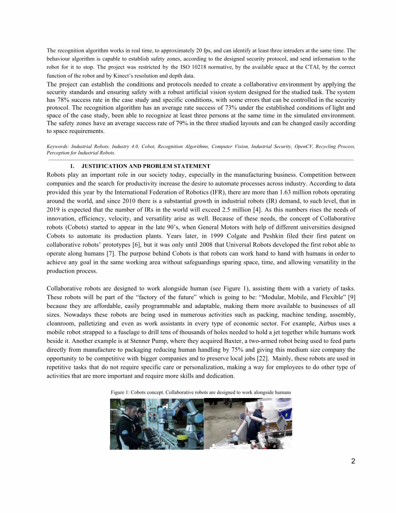
Figure 1: Cobots concept. Collaborative robots are designed to work alongside humans
2

Source: [9] Figure 2: Reduction of robot system costs compared to labor cost
Source: [14]
Figure 2 shows how costs are reduced and productivity increases as robot systems are implemented but finding a breakeven point between manual and robotic manufacturing, this happens because industries still need the expertise, reasoning, and perception of humans, especially in activities that require extreme care, flexibility and that have a high level of uncertainty. This is the main reason industries require a hybrid relationship between humans and robots, working hand to hand to achieve more productivity and reduce costs and time of readjusting in every manufacturing process or task without losing quality [14]. In order to achieve this balance, lots of new Cobots are being developed and are slowly making their way into the industry, especially in medium and small industries (SMEs). Companies like Universal Robots design and develop Cobots to relieve employees from monotonous task, ensure quality control, optimize production [9] and also to be affordable (at an average price of 24.000 USD [15]) and safe [10], which is ideal to these enterprises that have low budgets, insufficient space and where operators unavoidably must intrude in the robot’s security area. This type of layouts makes necessary the reduction of efforts in engineering and the reduction of limitations in implementing automation [11], making indispensable that the technological developments become more affordable and easier to carry out. That’s why Cobots are beginning to see a noticeable spike in popularity precisely because of their affordability, their low costs and their emphasis on safety [6]. Safety has been an important issue in each historical stage of robot’s development. At the beginning of the robotic industry, there were large and powerful hydraulic machines that were against of security of employees who worked around it, for that reason was necessary to cage off the robots from the world. This was a successful solution in normal operations, but it was not for the ones that needed human intervention. As time went on, the necessity to establish and create an environment where human could intervene and share the tasks of the robots increased. To ensure safety in the workplace, efforts began in the United States and Europe to establish and regulate the safety requirements for workers around IR [8]. Figure 3 shows history of industrial robots and their safety standardization.
3

Figure 3: History of industrial robots and their safety standardization.
Source: [8]
Nowadays the standards which govern the Cobots safety requirements and their relationship with the humans in an industrial environment are, for North America, the ANSI/RIA R15.06 while for Europe are the ISO 10218-1. Based in the European rule, this standard describes four general safety features for Cobots [8]:
1. Hand guiding: It’s a feature to teach a robot to do some task. A person guides the robot through a sequence of motions required to complete a task.
2. Power and force limiting: Some new series of Cobots do not require safety due to their limitation in power and force. This Cobots can read forces in their joints. This facilitates to stop or reverse its course.
3. Safety monitored stop: This feature is predominant in work alone Cobots. If an employee had to make some adjustment the Cobot will cease movement, but not completely shut down.
4. Speed and separation monitoring: This feature serve when the human intervention in the robot task is more frequent, a system vision is installed to sense human proximity. The robot will change its velocity according to the human approach.
These standards are of great importance because safety in the workplace is necessary to achieve great levels of productivity and to reduce costs. According to Gahan, Sievewright and Evans [12] the costs associated to workplace accidents are around 4% of annual global gross domestic productivity and the global competitivity index is strongly related to work fatality rates by nation, this means that a safe industry in every economic sector is crucial for future development and worldwide finances. Usually, companies that place higher in performances indexes (90%) rate very low in injury frequency, which translates in lower stops in production and lower costs in workplace accidents, whilst companies rating 70%, or lower, have injury frequencies about 60 times more [13]. This makes necessary a bigger control in every aspect of production whilst securing autonomy in every level to be more efficient and competitive. Safety and reliance are critical points in the adequate performance of Cobots, without them it would be impossible for the concept to exist. The collaboration is based in confidence between human and robot, the confidence of being safe and of working for the same objective, something that is still difficult to achieve because of the fear of being replace or to be injured [15]. According to the Occupational Safety and Health Administration [52] in the last eighteen years, twenty people have died or have been injured for a robot in accidents caused by human error, workplace design or robot design, which adds more pressure to safety in order to increase the use of Cobots. As the needs for more personal and automated tasks rise, the search to reduce uncertainty and to provide robots with better perception capabilities
4

arise as well. Likewise, the competitive environment of the market makes imperative the efficiency of the processes and the reduction of costs to offer products or services that adjust to society needs whilst adding value to them. These reasons make essential for Cobots to have strict but easy to program security protocols to ensure humans safety above all. That is why this project aims to design an operative and inexpensive system that will enhance safety and productivity in a waste separation task. The system will be composed by two algorithms; the first one will recognize human presence in the surroundings of the Cobot delivering the exact position of the intruders, whilst the second algorithm will determine the behaviour of the Cobot according to security protocols established by the norms and requirements of the industry. This system will ease the use and development of Cobots for waste separation industries, as it will allow to program the algorithms with simplicity in an open software, making the operation of the robot more affordable and comprehensible, as well creating a precedent of inexpensive systems for these industries and increasing safety whilst reducing barriers between workers and machines. This system will be applied in a recycling waste separation task in Colombia, where almost 50 million people produce 11.6 million tons of waste per year, and only recycle the 17%. All this garbage produces the 6% of the greenhouse gas emission in the country. Although many institutions talk about a growth in the recycling levels, there is no incentive for recycling or for take advantage of the waste [16]. These small industries usually combine the space for these activities with other process that are part of the company, that’s why the space tends to be small and very dynamic, with people always entering, doing classification, organizing, or receiving around 675 tons of plastic from different providers in a day [19, 21]. The initial required inversion is high, and the profit is proportional to the number of kilograms recycled which sometimes can be difficult to achieve because of the poor recycling education in the country that makes the separation process more complicated and expensive [20]. Therefore, this project will be the starting point to develop the environment for workers and robots in SMEs that may need to improve their process or to reduce the costs of the existing pollution indexes in the country by means of waste separation tasks, allowing to design narrow layouts with minor costs and with no affectation in safety in collaborative and productive line ups, aiming to continue what Pontificia Javeriana University (PUJ) has been developing at CTAI since 2016 with its PIR project (Perception for industrial robots). Based on the previously exposed situation, this project aims to answer the following research question: By using open source software (ROS-I, OpenCV) and the equipment available at CTAI, is it possible to develop a computer vision-based system that allows an industrial robot, executing waste separation tasks, to work with humans side by side ensuring their safety?
2. LITERATURE REVIEW The development of Cobots and safety has been researched along the last 30 years. A lot of these robots are programmed to stop at any change of weight or pressure in their extremities, to avoid damages to themselves and to humans, also they count with object recognition and avoidance to avert accidents [35]. As stated by Mathias et al. [23], to keep on collaborative development, security must be a critical point on the evolution of Cobots, these researchers developed two approaches to risk assessment, both combining mechanical design principles and simple control measures to supervise the robot and avoid free impact between human and robot. In the first approach they focus on safety certification according to common procedures to risk assessment and in the second approach they focus on the classification and modeling of low level injury mechanisms to soft tissues, all according to the ISO norm, proposing a complete framework to risk assessment for Cobots, based on the fact that this type of robot require less on
5
safety performance level of risk reduction measures according to estimations made that showed that the probability of dangerous failure is once every 38 to 114 years, because of the designs implemented in order to be collaborative. These findings will be used to develop the risk analysis in the project, to designate the safety areas and the levels of security needed in every setting, according to the robot’s specifications. A fundamental part of collaborative work is the comfortability and easiness that operators experiment when working with the robots, if the presence of these machines difficult the tasks by making workers uncomfortable then productivity and quality will decrease. To study this, researchers have conducted tests where the robot in action is presented to the operators whom later resolve a questionnaire to evaluate the effects of speed and distance, these studies show that larger robot body and faster robot speed movements made people uncomfortable, as well as the absence of any informative signal either visual or sonorous [59]. The Godspeed methodology is the most used for questionnaires, this methodology aims to measure the user’s perception of robots by means of scales, divided in five groups: anthropomorphism, animacy, likeability, perceived intelligence and perceived safety [60]. Other questionnaires to analyze the human-robot interaction are the NARS (2006) and BEHAVE-II (2013). The first measures the negative attitudes toward robots and its divided in three categories: situations of interaction with robots, the social influence of robots, and emotions in interaction with robots; the second one utilizes subjective and objective metrics to assess human responses to robot behavior considering two types of responses: attitudinal and behavioral. However, Godspeed is the most used because is the only open to the public and is also the easiest to modify and implement according to design necessities, that is why this will be used for the present work. In terms of safety assurance, Koskinen, Heikkila and Pulkkinen at [24], affirm that reliable safety consists of safety sensor systems, where binary produced information prevents collisions between robots and humans. These researchers developed an algorithm that in presence of humans, detected by a system of sensors (e.g. cameras, laser scanners, light curtains, safety mats or any type of positioning sensor), send signals for the robot either to stop, halt, restrict the direction or slow down its movements, informing in the User Interface (UI) its actions, needing intervention for continuing with specific tasks. By means of redundancy the system aims to produce more accurate data in order to make less mistakes and ensure a safety environment, mixing the capabilities of two or more sensors and maximizing its accuracy. In relation with human recognition, there are different approaches in literature, for example, in [49] the authors combine laser sensors with cameras to recognize humans, applying their findings in autonomous surveillance of large outdoor infrastructures, reducing the variations due to noise, distance and human pose recognition compared to other current methods. In [61] Rosebrock designed a simple algorithm capable to identify and follow a person by framing his/her body in a rectangle by means of background subtraction, using OpenCV, a raspberry pi and a camera, considering a static background and lighting, resulting in a very powerful and sensitive code that allowed to identify various intruders at once. The majority of this researches, employed specialized sensors and programs that can be expensive and difficult to manipulate because of licenses and maintaining, that is why low-cost alternatives as Kinect are beginning to be used in recognition algorithms as in [25], where is employed as an input device that gathers information so the robot can follow a human target with a method based on human characteristics, divided in human region segmentation, color feature extraction, body size feature extraction and combining color and body size, allowing the robot to follow a human target previously established and to identify more than one human, ignoring the not targeted ones and being careful not to collide with them. Another research conducted in Portugal had the objective of evaluate the sensing system for person detection in a mobile robotic platform for Ambient Assisted Living, these researchers considered two sensors: a 2D camera (webcam) and a depth sensor-Kinect, and developed different algorithms for each one,
6
finding that 2D face recognition can be used for short distances to identify a person, while skeleton (3D Kinect) tracking can be appropriate for distant and dynamic tracking [53]. The rising preference for Kinect sensors, beside its affordability, is due to the integration of IR sensors that can be used for determining depth, a feature that allows gathering information in three dimensions, also it does not need a lot of computer power to achieve good results with an operation range about 1.2 to 3.5 Meters ideally for indoor use, as seen in these studies. In the field of recycling many attempts have been made, coming up with new technologies and processes ruled by material classification and separation. In 2011 ZenRobotics revolutionized the industry by introducing a robotic waste sorter that was able to combine artificial vision, machine learning and artificial intelligence in order to pick recycled materials from a conveyor [27]. Later some other companies started to introduce robotics to their recycling processes like Sadako Technologies, who work in artificial intelligence garbage sorting systems by means of algorithms; AMP Robotics, Alpine Waste & Recycling and Carton Council worked together to develop “Clarke”, a robot that is capable to identify and separate food cartons from the rest of the batch, picking on average 60 cartons per minute [27]. According to the Global Waste Sorting Robots Market report there is a recent trend in pairing humans and robots for effective waste sorting, mostly because of the inaccuracy of humans of separating big amounts of materials and the tedious-based activity that this activity involves, making manufacturers develop new methods of waste separation, however the challenge of ensuring safety remains, because policies and best practices are not enough and accidents still occur in different processes [51]. The Yaskawa Motoman SDA10F, a dual arm robot has been used in other projects at the Pontificia Universidad Javeriana’s CTAI (Centro Tecnológico de automatización Industrial). N. Barrero and D. Galvis developed perception capabilities by means of image processing, their goal was to separate plastic wastes with artificial vision based on colors and shapes [28]. Another research was made by C. Céspedes and A. Pinzón, where they made a teleoperated control system using a Kinect with a servo-visual control, like the dynamic look and move, teaching and recreating the movements from a human by tracking reference points previously defined by artificial vision [29]. Eng. W. Hernandez and L. Patiño also conducted a research using a Kinect sensor that consisted in a vision algorithm that allowed the robot to perform a picking task of elements with different shapes and place them in a certain spot [55]. G. Garzón and L. López developed a security system using two Kinect sensors, ARDUINO and OpenNI, to detect whenever a person or object was close to the robot and stop immediately without distinction of speed, task or object [56]. As seen, these researches work on different topics, but there is not an altogether work for creating a safety system affordable and easy to program for SME industries, that is why this project aims to give the SDA10F human perception capabilities in industrial environments specifically in waste separation processes so safety standards can be assured and humans can work alongside them, also a low-cost sensor with the necessary requirements will be implemented, opening the possibilities for further research in other applications and the reduction of high investments in other devices that might reduce the budget in a project or that are designed for long range operations and would not be using their complete potential in small closed areas.
3. OBJECTIVES Develop a computer vision algorithm that enforces safety in a collaborative human-robot environment by establishing safety zones in the surroundings of the robot’s workspace.
a) Design and implement an algorithm that, through information acquired by a kinect sensor, provides the industrial robot with a constant detection and recognition of humans around itself.
b) Establish and describe safety zones and a dynamic security protocol for the industrial robot according to the physical structure of a waste separation task and the current standards.
7
c) Design and implement an algorithm that modifies the operation of the robot (e.g. its speed), according to the perceived information and previously established security zones, avoiding accidents around it.
d) Design and execute a test protocol to verify the efficiency performance of the system.
4. METHODOLOGY The project was developed at the Technological Center of Industrial Automation (CTAI), where there are different tools, instruments, devices and materials for the development of the proposed system.
The software used for developing the project was OpenCV library and ROS Kinetic. The first one was used for the recognition algorithm and the speed modification algorithm while the second was used for the communication with the robot in order to give commands trough information acquired by the recognition algorithm. To obtain the information acquired by the kinect (environment image and depth) the freenect library was used. The hardware used to run this software was a laptop. A ASUS X455L Intel Core i7 2.6GHz, 8GB RAM memory, running Ubuntu 16.04 with ROS kinetic installed with the following packages: Motoman driver kinetic devel, ROS Industrial indigo devel, freenect library and MoveIt!. The Kinect camera used for the project comes with a viewing angle of 43° vertical by 57° horizontal field, a vertical tilt range of , a frame rate of 30fps and a 2G/4G/8G accelerometer configured for the 2G range, with a 1° 7°± 2 accuracy upper limit. The resolution of the depth stream is dependent upon the frame rate and is given by the Depth Image Format Enumeration. The sensor’s performance depends on the environment settings such as light or reflectiveness of the elements [64]. The Camera is used for the human recognition algorithm in order to identify the movement in the work area. The depth sensor is used to retrieve the 3D position of the recognized subjects in order to know their position in the area. The robot used for the project was the Motoman, which is designed for packaging and small parts handling with payloads of 20 kg and under. It has 15 axes of motion, is capable of maintain 10 kg payload per arm and has a reach of 720 mm (horizontal per arm) and 1,440 mm (vertical per arm). For further specifications see the Motoman SDA10 instructions in [58].
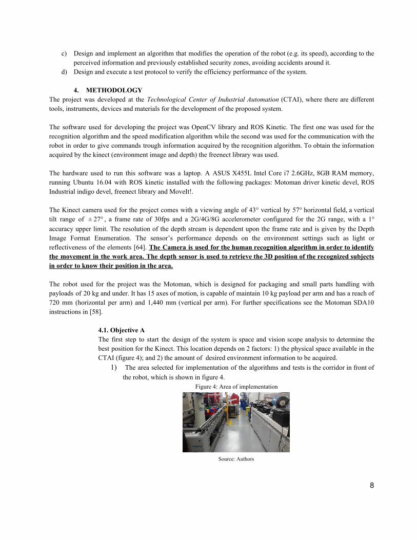
4.1. Objective A The first step to start the design of the system is space and vision scope analysis to determine the best position for the Kinect. This location depends on 2 factors: 1) the physical space available in the CTAI (figure 4); and 2) the amount of desired environment information to be acquired.
1) The area selected for implementation of the algorithms and tests is the corridor in front of the robot, which is shown in figure 4.
Figure 4: Area of implementation
Source: Authors
8
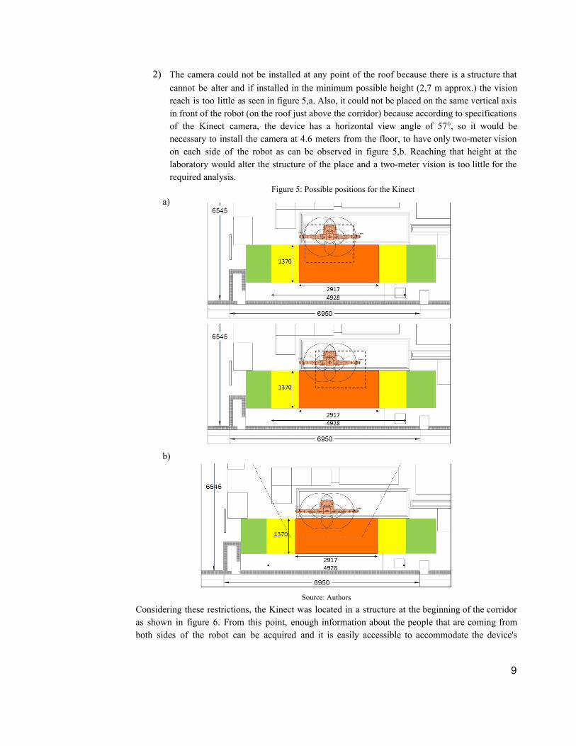
2) The camera could not be installed at any point of the roof because there is a structure that cannot be alter and if installed in the minimum possible height (2,7 m approx.) the vision reach is too little as seen in figure 5,a. Also, it could not be placed on the same vertical axis in front of the robot (on the roof just above the corridor) because according to specifications of the Kinect camera, the device has a horizontal view angle of 57°, so it would be necessary to install the camera at 4.6 meters from the floor, to have only two-meter vision on each side of the robot as can be observed in figure 5,b. Reaching that height at the laboratory would alter the structure of the place and a two-meter vision is too little for the required analysis.
Figure 5: Possible positions for the Kinect a)
b)
Source: Authors
Considering these restrictions, the Kinect was located in a structure at the beginning of the corridor as shown in figure 6. From this point, enough information about the people that are coming from both sides of the robot can be acquired and it is easily accessible to accommodate the device's
9
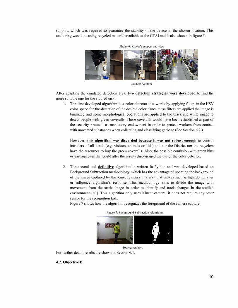
support, which was required to guarantee the stability of the device in the chosen location. This anchoring was done using recycled material available at the CTAI and is also shown in figure 5.
Figure 6: Kinect’s support and view
Source: Authors
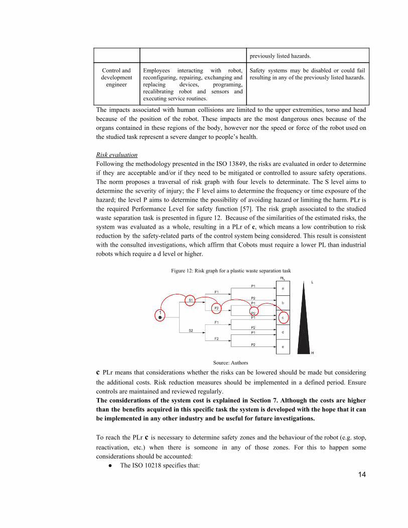
After adapting the emulated detection area, two detection strategies were developed to find the more suitable one for the studied task:
1. The first developed algorithm is a color detector that works by applying filters in the HSV color space for the detection of the desired color. Once these filters are applied the image is binarized and some morphological operations are applied to the black and white image to detect people with green coveralls. These coveralls would have been established as part of the security protocol as mandatory endowment in order to protect workers from contact with unwanted substances when collecting and classifying garbage (See Section 6.2.). However, this algorithm was discarded because it was not robust enough to control intruders of all kinds (e.g. visitors, animals or kids) and nor the District nor the recyclers have the resources to buy the green coveralls. Also, the possible confusion with green bins or garbage bags that could alter the results discouraged the use of the color detector.
2. The second and definitive algorithm is written in Python and was developed based on Background Subtraction methodology, which has the advantage of updating the background of the image captured by the Kinect camera in a way that factors such as light do not alter or influence algorithm’s response. This methodology aims to divide the image with movement from the static image in order to identify and track changes in the studied environment [69]. This algorithm only uses Kinect camera, it does not require any other sensor for the recognition task. Figure 7 shows how the algorithm recognizes the foreground of the camera capture.
Figure 7: Background Subtraction Algorithm
Source: Authors
For further detail, results are shown in Section 6.1.
4.2. Objective B
10

The Motoman SDA10F is a safe robot that satisfies the Performance Levels and safety evaluation specified in the ISO 13849, as well as it fulfill the requirements of the ISO 10218-1. Considering this, the objective is focused on the robot system and the integration with the industrial task, aiming to create the desire collaborative environment. In order to create this environment, first is necessary to understand the whole recycling process, which is shown in figure 8.
Figure 8: Recycling process
Source: Authors
According to the ISO 10218-2, is necessary to identify the hazards and to assess the risks associated with the robot and its application before selecting and designing appropriate safeguarding measures to reduce the risks, to determine robot speed, to define the minimum separation distance and other required parameters (article 5.11.5.4) [33]. To ensure the compliance of the norm is necessary to do a risk assessment, which consists in the determination of the limits of the robot system; hazard identification; risk estimation and risk evaluation. This analysis is made supposing that the robot is already in place, in order to implement a safety system for the automated task. Limits of the robot system The norm specifies four types of limits:
1. Use limits: The Motoman, provided with claps and kinect sensors, will be
developing picking of various plastic elements into categories, according to a recognition CV library and a previously established algorithm, that stops when there is not elements to pick and when the operator stops it manually (making use of the previous work realized by Barrero and Galvis in [28]). The only manual intervention will be when loading and unloading the elements to the robot’s workspace. The diagram of the proposed process can be seen here. The use is also limited by tooling and equipment, in this case the Kinect sensor, the Motoman FS100 controller and the computer power, which are listed before in the start of this chapter.
As stated before the Motoman robot was designed under specific compliance of safety norms, which allows to consider the robot inherently safe and no further mechanical or electronic assessment is required. The security of the system will be determined by the protocols and programming associated to the task. For its operation in plant is necessary to know how to read (if an emergency stop is needed) for the restart procedure. The programming skills will be needed only in case of changes in the task or malfunction of the system.
2. Space limits: As described in the problem statement, the general layout for waste
separation tasks in Colombia is characterized by narrow spaces in which there are
11

various activities being held at the same time at undefined areas and in undetermined periods of time, which create the need of a very flexible and adaptable layout that would be able to change according to the daily waste load, whether it is more plastic, paper, cardboard or electronic wastes.
Therefore, the layout design in Figure 9, aims to represent a general organization of these industries accommodated to the space in the CTAI and complying with the ISO 10218-2.
Figure 9: Layout of recycling task at CTAI
Source: Authors
The arrows represent where there are traffic routes of collaborators, while the blue squares represent the bulks of materials in the area. The control systems and the support services are signposted, as well as the exit routes. This design considers the real life layout of the waste separation task in La Alqueria, which is shown in Figure 10. This recycling center has two compressors two classification stations, one transformation station and the materials are placed randomly in the available space. One important feature to consider is the table measures seen in figure 11, because this take a lot of space from the available space for transit and covers a great part of the corridor in the CTAI simulation.
Figure 10: Layout of recycling task at La Alqueria
Source: Authors
12

Figure 11: Workstation for Plastic Separation
Source: Authors
3. Time limits: For the application considered, a whole cycle takes about 16 seconds. This time cycle is approximate and is taken from the video presented in [58] which mean that every phase could take more or less time and depends on the position and form of the bottles.
4. Other limits: Materials: the plastic materials of the elements of classification tend to be slippery and sometimes fell out of the workspace, which limits the actual grasp of the robot.
Hazard identification ● The mechanical hazards associated to the studied application are: movements of any part of
the robot arm and end-effector; rotational motion of any robot axes; materials and products falling or ejection; end-effector failure (separation); loose clothing, long hair; unintended movement during handling operations; unintended motion or activation of an end-effector or associated equipment and unexpected release of potential energy from stored sources.
● The combined hazards associated to the studied application are: robot system directed to start by one person, but this action is not expected by another person; misidentification of actual problem and compound problem by making incorrect or unnecessary actions; unintended release of holding devices allowing motion under residual forces.
Risk estimation The potential risks associated to the task are described in terms of the roles that can interact with the robot and the impacts that can be generated by that interaction.
Table 1: Risk estimation
Role Role Description Impact
Visitor Internal or external person with no information about hazards.
Enters in dangerous contact with robot resulting in any of the previously listed hazards.
Other worker Employees coming close to the robot occasionally with no required interaction with it.
Enters in dangerous contact with robot resulting in any of the previously listed hazards and interrupting employers’ task indefinitely as well.
Co-existing worker
Employees working in an overlapping workspace with the robot doing independent task.
Hits or get hit by the robot accidentally resulting in any of the previously listed hazards.
Collaborating worker
Employees interacting with robot in regular operating mode.
Hits or get hit by the robot due to error of proceeding or machine resulting in any of the
13
previously listed hazards.
Control and development
engineer
Employees interacting with robot, reconfiguring, repairing, exchanging and replacing devices, programing, recalibrating robot and sensors and executing service routines.
Safety systems may be disabled or could fail resulting in any of the previously listed hazards.
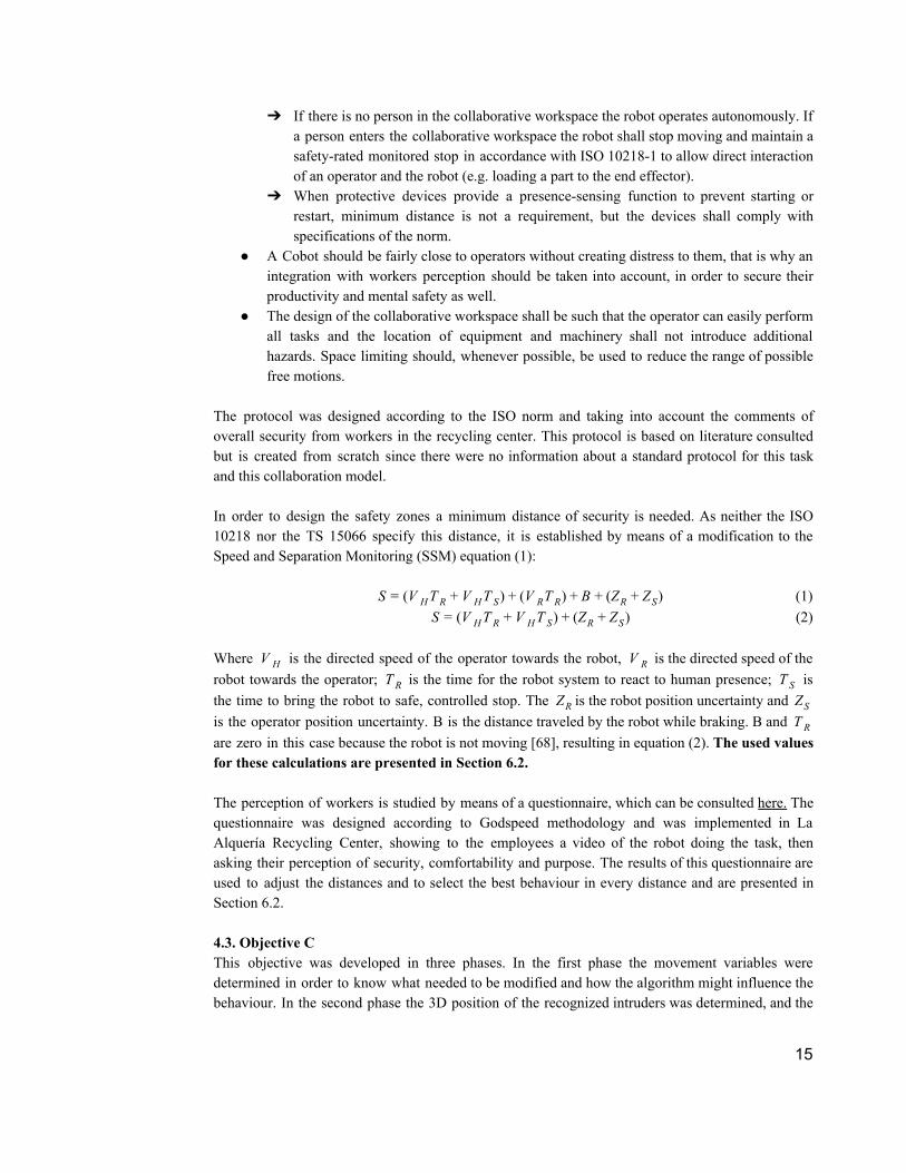
The impacts associated with human collisions are limited to the upper extremities, torso and head because of the position of the robot. These impacts are the most dangerous ones because of the organs contained in these regions of the body, however nor the speed or force of the robot used on the studied task represent a severe danger to people’s health. Risk evaluation Following the methodology presented in the ISO 13849, the risks are evaluated in order to determine if they are acceptable and/or if they need to be mitigated or controlled to assure safety operations. The norm proposes a traversal of risk graph with four levels to determinate. The S level aims to determine the severity of injury; the F level aims to determine the frequency or time exposure of the hazard; the level P aims to determine the possibility of avoiding hazard or limiting the harm. PLr is the required Performance Level for safety function [57]. The risk graph associated to the studied waste separation task is presented in figure 12. Because of the similarities of the estimated risks, the system was evaluated as a whole, resulting in a PLr of c, which means a low contribution to risk reduction by the safety-related parts of the control system being considered. This result is consistent with the consulted investigations, which affirm that Cobots must require a lower PL than industrial robots which require a d level or higher.
Figure 12: Risk graph for a plastic waste separation task
Source: Authors
c PLr means that considerations whether the risks can be lowered should be made but considering the additional costs. Risk reduction measures should be implemented in a defined period. Ensure controls are maintained and reviewed regularly. The considerations of the system cost is explained in Section 7. Although the costs are higher than the benefits acquired in this specific task the system is developed with the hope that it can be implemented in any other industry and be useful for future investigations. To reach the PLr c is necessary to determine safety zones and the behaviour of the robot (e.g. stop, reactivation, etc.) when there is someone in any of those zones. For this to happen some considerations should be accounted:
● The ISO 10218 specifies that: 14
➔ If there is no person in the collaborative workspace the robot operates autonomously. If a person enters the collaborative workspace the robot shall stop moving and maintain a safety-rated monitored stop in accordance with ISO 10218-1 to allow direct interaction of an operator and the robot (e.g. loading a part to the end effector).
➔ When protective devices provide a presence-sensing function to prevent starting or restart, minimum distance is not a requirement, but the devices shall comply with specifications of the norm.
● A Cobot should be fairly close to operators without creating distress to them, that is why an integration with workers perception should be taken into account, in order to secure their productivity and mental safety as well.
● The design of the collaborative workspace shall be such that the operator can easily perform all tasks and the location of equipment and machinery shall not introduce additional hazards. Space limiting should, whenever possible, be used to reduce the range of possible free motions.
The protocol was designed according to the ISO norm and taking into account the comments of overall security from workers in the recycling center. This protocol is based on literature consulted but is created from scratch since there were no information about a standard protocol for this task and this collaboration model. In order to design the safety zones a minimum distance of security is needed. As neither the ISO 10218 nor the TS 15066 specify this distance, it is established by means of a modification to the Speed and Separation Monitoring (SSM) equation (1):
(1)V T T ) V T ) Z )S = ( H R + V H S + ( R R + B + ( R + ZS (2)V T T ) Z )S = ( H R + V H S + ( R + ZS
Where is the directed speed of the operator towards the robot, is the directed speed of the V H V R robot towards the operator; is the time for the robot system to react to human presence; is T R T S the time to bring the robot to safe, controlled stop. The is the robot position uncertainty and ZR ZS is the operator position uncertainty. B is the distance traveled by the robot while braking. B and T R are zero in this case because the robot is not moving [68], resulting in equation (2). The used values for these calculations are presented in Section 6.2. The perception of workers is studied by means of a questionnaire, which can be consulted here. The questionnaire was designed according to Godspeed methodology and was implemented in La Alquería Recycling Center, showing to the employees a video of the robot doing the task, then asking their perception of security, comfortability and purpose. The results of this questionnaire are used to adjust the distances and to select the best behaviour in every distance and are presented in Section 6.2. 4.3. Objective C This objective was developed in three phases. In the first phase the movement variables were determined in order to know what needed to be modified and how the algorithm might influence the behaviour. In the second phase the 3D position of the recognized intruders was determined, and the
15

safety zones were established in the real space according to the safety protocol. Finally, in the third phase the way to send the information to change robot’s behaviour was determined. The movement variables to modify robot’s operation are parameters determined by ROS framework and the MoveIt! Package, which is used for planning a desired trajectory, visualizing it in RViz and subsequently executing it. The robot itself behaves differently according to the planned path, considering that different joints are involved in its movement and consequently the trajectory could require different joint speeds, so the robot, as a whole can react fluidly. The MoveIt! Package allows the user to determine a maximum velocity and acceleration for every single joint, saving the information in a .yaml file. The robot’s motion will then be determined by a percentage of the joints maximum parameters expressed in values between 0 to 1. In MoveIt!, speed is controlled through “Time Parametrization”, where time constraints are given to kinematic trajectories for speed and acceleration values, either from the previously mentioned .yaml file or during runtime through spin boxes found in RViz [71]. On the other hand, to modify the characteristics of the robot, is necessary to know the 3D location of the intruders in reference to the established safety zones, by means of Kinect's depth sensor. To do that, two aspects had to be completed:
1. Camera calibration. 2. Loading information about the established zones in the previous objective.
The camera had to be calibrated to find the intrinsic parameters to determine the 3D position of both the zones and the intruders’ contours. For this calibration the chessboard technique was implemented, which aims to convert the points of interest of UV coordinates to XYZ coordinates.
Figure 13: Kinect calibration
Source: Authors
The equations used for the conversion of the data were the following:
(3) X , , ) P = ( Y Z = Z( ( fuu − Cu) , Z ( fv
v − Cv) , Z)
Where u,v are the pixel coordinates and Cu, Cv, fu and fv are the intrinsic parameters.
(4) 0.1236 tan(depth info / 2842.5 1.1863) Z = * +
Where depth info is the value the value obtained from the depth sensor.
16

Once the calibration is realized, the algorithm of color detection (developed and discarded in objective 1) s used to load the information of the established zones. This process has three stages (See Figure 14):
1. The location of the different security zones, drawing their perimeter on the corridor floor. 2. The positioning of a green rectangular object in each of the vertices of the zones to store the coordinates of each of the eight points corresponding to the security zones. The algorithm stores the XYZ coordinate corresponding to the centroid of the green object placed at the vertex of the zone. 3. The creation of the four perpendicular planes using basic mathematics for every safety zone.
Figure 14: Safety Zones parametrization
Source: Authors Likewise, the distance was calibrated by realizing manual calibration with little objects, testing their real distance from the Kinect and comparing it with the result given by the code, adjusting the number according to the difference between the results. The algorithm has the flexibility to create zones at discretion, according to the available space. However, it should be noted that the construction of the zones has some restrictions:
1. The zones must be cubic. The algorithm can only create and estimate four-sided zones. 2. Obtaining information on each of the vertices of the zones must be done through an established organization. The process can be seen here.
The parametrization of the established zones and the algorithm used in the first objective were the inputs to determine in which zone the detected persons were located and the corresponding speed scale to communicate to the robot. To achieve that, an algorithm that analyzes the location of the points that conform the contours found with respect to the limits established in the creation of the zones was created. The output of this algorithm is a signal that describes in which zone these points are located. To modify robot’s behaviour there must be a connection established between the algorithm and ROS, where information can be exchanged. To achieve this goal, a ROS Node and Topic had to be created. The way ROS behaves with Topics and Nodes consist in publishers and subscribers, where Nodes have any kind of information or process and can communicate between themselves for any purpose through Topics only. A Node can publish to any Topic and another can subscribe to it to receive the information and use it for another process. The system designed uses MoveIt! To plan the desired trajectory (first seen and parameterized in RViz), showing the calculated path with its initial and final position [72]. These processes occur through a node called move_group, which acts as an integrator of every individual component in order to compound a final ROS service with all its capabilities. The ideal scenario for controlling the
17

speed through the algorithm is to create a node that can communicate with the move_group node through a topic, so that the main speed control values are given by the camera readings. For further details on the algorithm see Section 6.3. 4.4. Objective D As the objective aims to elaborate a test protocol to measure system’s performance is not necessary an experimental design (e.g. ANOVA, etc.) to determine factors of interest. What is required is a set of indicators and tests that allows to determine if the system can classify humans in the safety zones and recognize them in the work area with different conditions chosen accordingly to the interests of the study, and also to verify how effective is the system in accomplishing the main objective. The test protocol was designed in three phases to measure the efficiency of the algorithms and the system as a whole:
I. Test for recognition algorithm: this test will measure how many people can be recognized in the work space, by analyzing a determined number of frames, in which three persons continuously get in and out of the studied zones.
How it is measure: The data printed by the algorithm is compared, by means of contingency tables, with the data observed “manually” by the authors, analyzing frame by frame to measure the outcomes calculating the accuracy.
II. Test for the system: this test will measure how many people can be recognized correctly when entering in a safety zone, emitting the right signal to the communication node.
How it is measure: By analyzing a determined number of frames in which a person walking through the safety zones, at different speeds and direction, is detected, comparing the results of the algorithm versus the expected values, calculating the accuracy and the F1-Score.
III. Test for safety zones: this will test the flexibility of the safety zones and the multiple changes that can be made without modify the objective of the safety system. The zones will be proved by separating them, having one inside the other and changing sizes in different spaces.
How it is measure: In every setting a determined number of frames is analyzed to prove the accuracy of the zones algorithm. The frames show one person walking through the zones and the information given by the algorithms is compared with the expected results, calculating the accuracy..
IV. Light test: this will test the influence of light in the performance of the safety system. This will be measure with two different light conditions: 500 lux and 15 lux,
How it is measure: following the same process in test II for every light condition and calculating the accuracy for each one.
The tests were realized by means of confusion matrices were different errors were measured to prove the performance of the algorithms. This methodology was used according to [75]. Confusion matrices aim to find the accuracy in binary applications and consists of columns and rows that list the actual class vs. predicted class ratios [74]. True positive are the values correctly predicted as positive. False negative are the values that should be negative but turn out positive. Both false negatives and false positives can be considered the errors of the system (type I error and type II error, respectively).
18
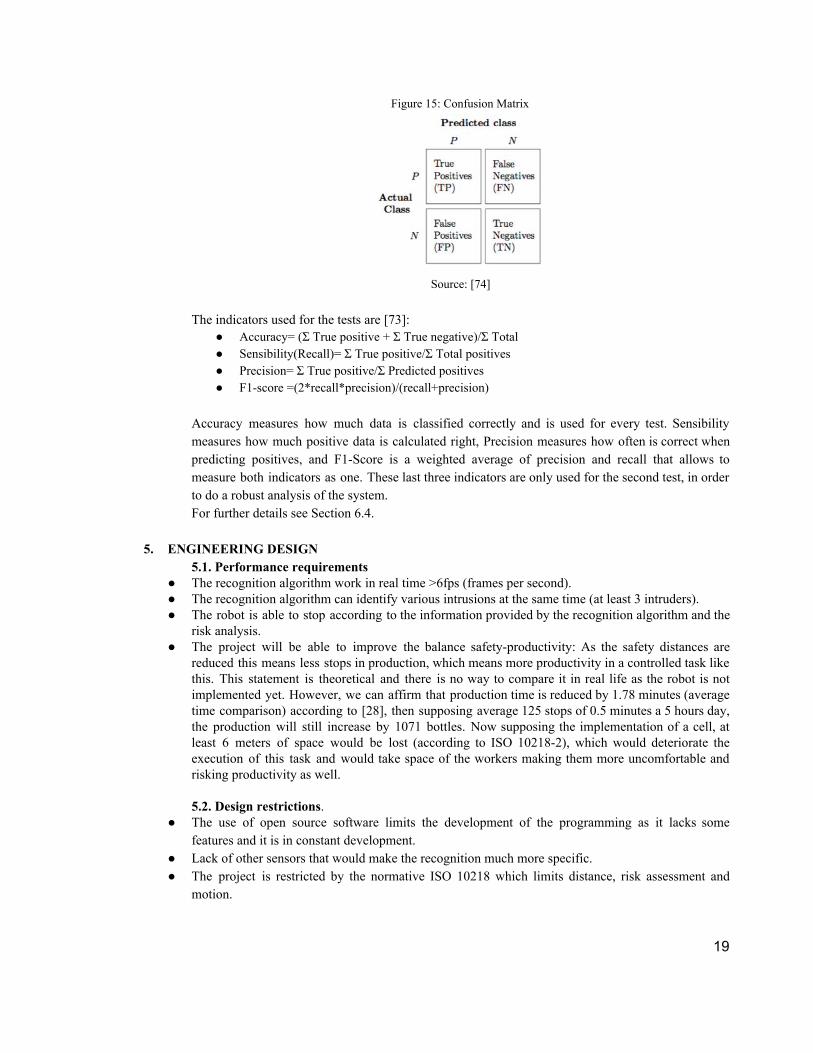
Figure 15: Confusion Matrix
Source: [74]
The indicators used for the tests are [73]:
● Accuracy= (Σ True positive + Σ True negative)/Σ Total ● Sensibility(Recall)= Σ True positive/Σ Total positives ● Precision= Σ True positive/Σ Predicted positives ● F1-score =(2*recall*precision)/(recall+precision)
Accuracy measures how much data is classified correctly and is used for every test. Sensibility measures how much positive data is calculated right, Precision measures how often is correct when predicting positives, and F1-Score is a weighted average of precision and recall that allows to measure both indicators as one. These last three indicators are only used for the second test, in order to do a robust analysis of the system. For further details see Section 6.4.
5. ENGINEERING DESIGN 5.1. Performance requirements
● The recognition algorithm work in real time >6fps (frames per second). ● The recognition algorithm can identify various intrusions at the same time (at least 3 intruders). ● The robot is able to stop according to the information provided by the recognition algorithm and the
risk analysis. ● The project will be able to improve the balance safety-productivity: As the safety distances are
reduced this means less stops in production, which means more productivity in a controlled task like this. This statement is theoretical and there is no way to compare it in real life as the robot is not implemented yet. However, we can affirm that production time is reduced by 1.78 minutes (average time comparison) according to [28], then supposing average 125 stops of 0.5 minutes a 5 hours day, the production will still increase by 1071 bottles. Now supposing the implementation of a cell, at least 6 meters of space would be lost (according to ISO 10218-2), which would deteriorate the execution of this task and would take space of the workers making them more uncomfortable and risking productivity as well.
5.2. Design restrictions.
● The use of open source software limits the development of the programming as it lacks some features and it is in constant development.
● Lack of other sensors that would make the recognition much more specific. ● The project is restricted by the normative ISO 10218 which limits distance, risk assessment and
motion.
19

● The recognition algorithm uses 2D vision technology extracting the Kinect’s depth data to perform the 3D pose estimation.
● The project is restricted by the space at the CTAI. ● The project is restricted by the correct operation of the robot. ● The tests are limited by the availability of time of the CTAI and of the staff authorized to manage
and control Motorman connections. ● The safety zones and protocol are limited by the information acquired by means of the qualitative
study of the recycling center operators’ perception. ● The RGB max resolution is 1280x1024 and for depth image is 640x480 at 15 Hz and 30 Hz
respectively. ● The human recognition algorithm must be fast. This is achieved because the velocity is about 20 fps. ● The behaviour algorithm must be fast to avoid accidents in real time. Which is achieved by having a
reaction time of . 5.3 Norms and standards fulfillment. As mentioned in section 4.2, the norms that rule the collaborative work with robots and the scope of this work, are:
● ISO 10218-1: specifies requirements and guidelines for the inherent safe design, protective measures and information for use of industrial robots.
● ISO 10218-2: specifies requirements for robots’ systems and integration, as well for collaborative work. It describes basic hazards associated with robots and provides requirements to eliminate, or adequately reduce, the risks associated with these hazards.
● ISO 13849: establishes a methodology for risk assessment. ● ISO 13855: establishes the positioning of safeguards regarding the approach speed of parts of the
human body. ● ISO/TS 15066: provides guidelines for the design and implementation of a collaborative workspace
that controls risk. It is based on the ISO 10218. ● ISO 23570-1:2005: Industrial automation systems and integration – Distributed installation in
industrial applications – Part 1: Sensors and actuators.
The distance specifications could not be achieved completely because of CTAI’s space.
6. RESULTS 6.1. Results Objective A
Design and implement an algorithm that, through information acquired by a kinect sensor, provides the industrial robot with a constant detection and recognition of humans around itself. The algorithm has four stages. The first stage is to detect the background of the image using the OpenCV function createdBackgroundSubtractionMOG()[70] with input parameters—determined experimentally—history:1000;nmixture:3;backgroundratio:0,7. The history is the number of past frames that the function should take into account for comparing and subtracting the background; the background ratio is the comparison point to determine if a foreground pixel in any of the last frames(ratio*history) should be added as part of the background given its constant value. As for the nmixture, figure 16 shows that the image has a clearer definition of the silhouette (with less black spaces) when a lower value is established. This MOG function estimates the static image (background) and the image with movement (foreground).
20

The second stage is the binarization of the image to make the detection operation easier by transforming the real data into zeros and ones, or in other words, converting the image to black and white, in order to find and differentiate the steady image of the changing image. This binarized image is called a mask
Figure 16: Inputs Parameters
a) nmixture = 5 b) nmixture = 3
Source: Authors
The third stage is the application of the dilate and closing morphological functions to the foreground in the mask, in order to achieve a better estimation of the contours found by the algorithm (white silhouettes in mask—figure 17). The dilate function increases the white region of the mask and the closing function seal black holes in the white silhouettes [65]. The last stage is to frame the silhouettes using an OpenCV function called findContours which determines the location of the continuous points along the white image boundary. With the information of the found contours is easy to draw a rectangle, enclosing the silhouettes in the original image to show the detection of movement in the environment. Figure 16 shows the resume of the process made by the recognition algorithm. Since a subtraction of the background was made and we only focused on determining movement in the image, it was not necessary to change the default color model in the image of the kinect camera (BGR color model), but in order to be able to observe the video captured by the camera better, the color mode was changed to RGB.
Figure 17: Human Detection flowchart
Source: Authors
21

This algorithm is capable to detect humans moving in front of the robot in the collaborative workspace, in order to avoid the greater amount of possible accidents according to the risk assessment. It also has a very robust behavior with respect to lighting changes that exist in the environment, since the reference image is updated constantly. Likewise, it has a fast reaction to existing movement changes in the image, which is important for the detection of movement in real time. For further detail on algorithm’s performance see Section 6.4.
6.2. Results Objective B
Establish and describe safety zones and a dynamic security protocol for the industrial robot according to the physical structure of a waste separation task and the current standards. The design of the safety zones starts with the calculation of the minimal distance of security using equation (2), resulting in:
V T T ) Z )S = ( H R + V H S + ( R + ZS (2) (1600mm/s .000105801s) 1600mm/s .1s)) 0.1mm 00mm) 60, mm S = ( * 0 + ( * 0 + ( + 4 = 5 3
is taken from the average human speed in ISO 13855.V H
is taken from expected Motoman’s stopping times in [63] adjusting the values to the specificT S task.
is calculated experimentally in the vision algorithm.T R is taken from robot’s manual (Repetitive Positioning Accuracy according to ISO 9283 and ISOZR
10218) is taken from Kinect’s specification vision range according to [53].ZS
Questionnaires results The S distance is coherent with the results of the questionnaires because 100% of the studied recyclers prefer that the robot stops when they get close at 0,5m of distance, while the 43% prefers that it stops when they get close at 1m of distance and 100% prefers that it keeps moving when the distance is equally or greater than 1,5m. For the related to the task layout, 100% of the surveyed recyclers prefer to work with the robot facing them, if needed 76% prefer to work with the robot at their right side while 29% does not care if is either right or left. In relation to security, 86% considered that the robot might not hurt them and they tend to feel surprise (43%) —because 100% of them have never worked with a robot and 57% has never seen a robot— but at the same time they feel confidence on the programming of the robot (33%) (“if it is not programmed to hurt us it will not be a threat”). In relation to utility, 100% considers it will be useful for the development of their tasks and 86% consider it very intelligent and capable. Regarding sympathy, results are peculiar, as 100% said they will consider the robot as a partner, 43% find it pleasant and the rest did not believe it was friendly. The latter is backed up by their perception of the robot’s anthropomorphism, 91% said it looked artificial and regarding animacity workers considered that the robot was fluid and somewhat autonomous, but it was not alive. In general, recyclers average perception is about 55 points of the 110 possible, which means that it is not totally negative nor totally positive, which was better than expected since given the background and initial attitude of the recyclers some reluctance was anticipated. As seen in figure 18, anthropomorphism is the lowest rated item with an average acceptance of 23,43% which means the
22
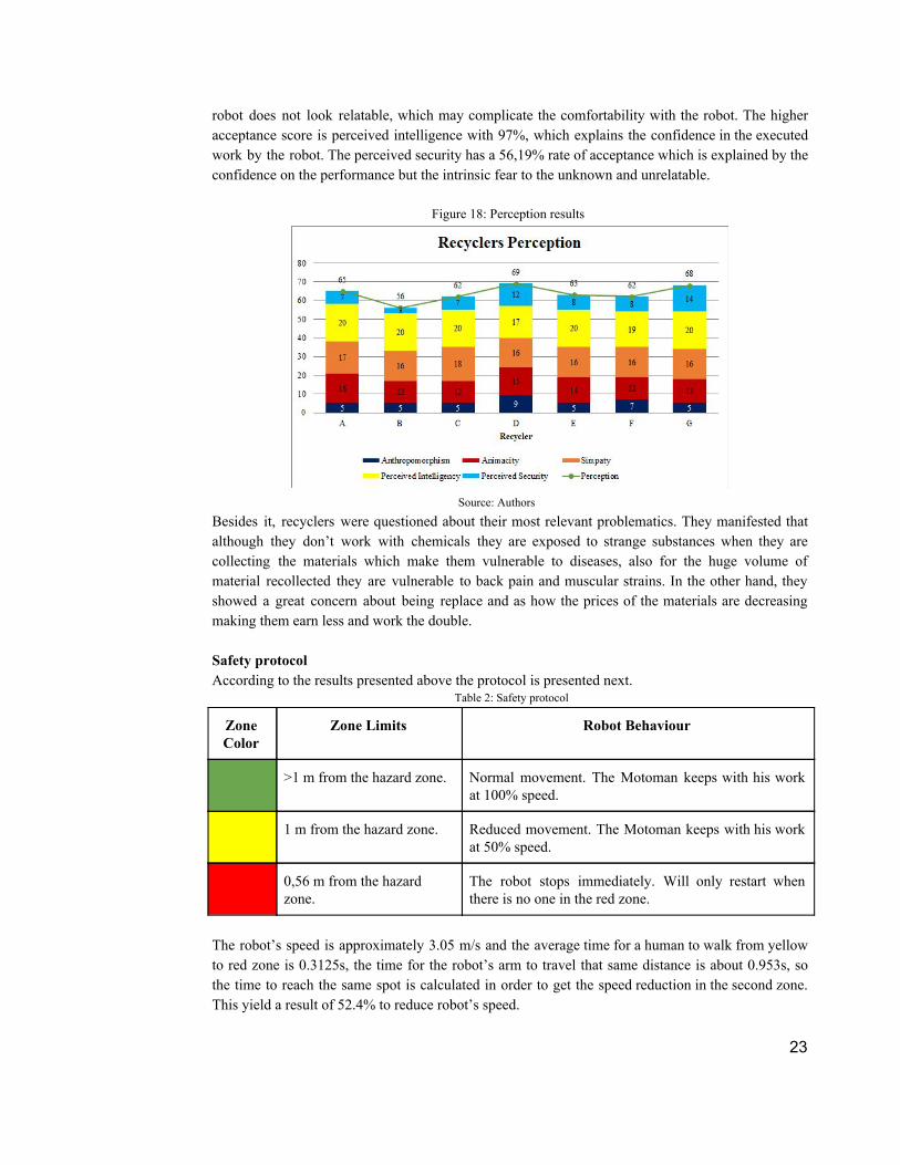
robot does not look relatable, which may complicate the comfortability with the robot. The higher acceptance score is perceived intelligence with 97%, which explains the confidence in the executed work by the robot. The perceived security has a 56,19% rate of acceptance which is explained by the confidence on the performance but the intrinsic fear to the unknown and unrelatable.
Figure 18: Perception results
Source: Authors
Besides it, recyclers were questioned about their most relevant problematics. They manifested that although they don’t work with chemicals they are exposed to strange substances when they are collecting the materials which make them vulnerable to diseases, also for the huge volume of material recollected they are vulnerable to back pain and muscular strains. In the other hand, they showed a great concern about being replace and as how the prices of the materials are decreasing making them earn less and work the double. Safety protocol According to the results presented above the protocol is presented next.
Table 2: Safety protocol
Zone Color
Zone Limits Robot Behaviour
>1 m from the hazard zone. Normal movement. The Motoman keeps with his work at 100% speed.
1 m from the hazard zone. Reduced movement. The Motoman keeps with his work at 50% speed.
0,56 m from the hazard zone.
The robot stops immediately. Will only restart when there is no one in the red zone.
The robot’s speed is approximately 3.05 m/s and the average time for a human to walk from yellow to red zone is 0.3125s, the time for the robot’s arm to travel that same distance is about 0.953s, so the time to reach the same spot is calculated in order to get the speed reduction in the second zone. This yield a result of 52.4% to reduce robot’s speed.
23
As part of the safety protocol, some safeguards and requirements are specified for the correct implementation of the system:
● The maximum reach of the robot must be always between the boundaries of the workspace (table for plastic separation). If this reach exceeds the workspace, safeguards must be implemented. These safeguards must be equally long as the corridor and the width (or the distance for protection) must compensate the length that is no covered by the table (70 cm wide). The height does not affect the system, however according to ISO 10218-2, this should be at least 1400mm from adjacent walking surfaces.
● Safeguards should be barriers, grids or any fixed structure that impedes the passage. ● The red zone will start from the maximum reach of the robot. The robot’s workspace is
green zone (safe) because there is no possible reach that cannot be controlled in advance. ● The system depends on the adequate design of the safety zones, that is why is important to
adjust the zones in a way that there is no intrusion detected that does not count with safeguards to avoid contact with the robot.
● Collaborative workspace where direct human robot interaction takes place must be clearly defined and signposted.
● The robot system should provide a minimum clearance of 500 mm from the operating space of the robot (including arm, any attached fixture and the workpiece) to areas of building, structures, utilities, other machines, and equipment that allow whole body access and may create a trapping or a pinch point.
● People must not stop for long periods of time in the red or yellow zone. These are passage zones and must not be obstructed.
● Shadows in bright surfaces may interfere with the results of the recognition algorithm so any big reflectant object or area (e.g. Floor) must be cover or removed from the collaborative workspace.
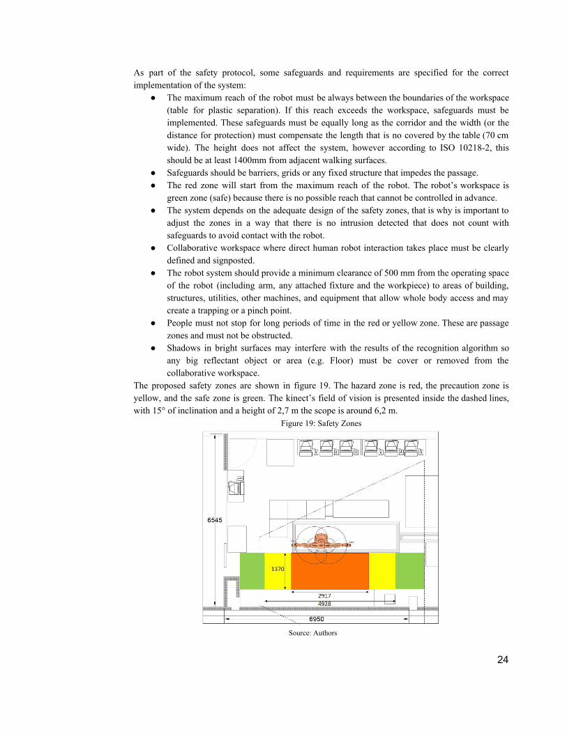
The proposed safety zones are shown in figure 19. The hazard zone is red, the precaution zone is yellow, and the safe zone is green. The kinect’s field of vision is presented inside the dashed lines, with 15° of inclination and a height of 2,7 m the scope is around 6,2 m.
Figure 19: Safety Zones
Source: Authors
24

6.3. Results Objective C Design and implement an algorithm that modifies the operation of the robot (e.g. its speed), according to the perceived information and previously established security zones, avoiding accidents around it.
As seen in section 4.3, the designed solution consists in a framework created over a distributed system. The proposed framework features three main modules. The first one is the human detection algorithm and the algorithm to load the safety zone limits information (See section 4.3.); the second module is the algorithm that determines in which of the safety zones is the detected person, issuing a signal that establishes the speed scale that the robot should adopt according to the occupied zone; and the third module is the communication of this signal to the robot. The framework is presented in figure 20.
Figure 20: Designed Framework
Source: Authors
Occupied zone module: The algorithm to determine if a zone is occupied was developed by conditionals. If any found contour point is inside the established limits of the created zones, the algorithm indicates the corresponding color of the occupied zone. Figure 21 shows the three different existing cases and an example can be seen here.
Figure 21: Human detection in different zones
Source: Authors
Communication Module: At the time of integrating this algorithm with the robot, it is important to note that all the parameters inside MoveIt! get fixed before every motion plan and stay the same until the trajectory is over, giving control to the FollowJointTrajectory action server so the planned path can be executed, resulting in lack of control on the run inside the Package and makes it impossible to change the maximum velocity percentage parameters while the robot is executing a task. However, the ROS Node called VelNodo and the Topic called TesisTopic were created with the algorithm, so
25

the information can be used in the future by the motion_control node if the MoveIt! Package is upgraded allowing speed control on the run or if another package is used. The algorithm is in fact the ROS Node and acts as a publisher to the Topic, printing the different speed parameters (0% - Red Zone, 50% - Yellow Zone, 100% - Green Zone) given by the code, and opening the possibility to any other Nodes to subscribe to the Topic and use the information for any desired purpose. Figure 22 shows the results of the created Node and Topic.
Figure 22: Node and Topic
Source: Authors
6.4. Results Objective D Design and execute a test protocol to verify the efficiency performance of the system.
First Test: This test has the objective to determine the effectiveness of the recognition algorithm regardless of the safety protocol. For this test a video composed by 403 frames was recorded, but only the 346 frames where at least one person was present were taken for the analysis. This video was recorded continuously and shows three people entering the workspace at different times, speeds and clothes. Figure 23 shows some frames of the test video. The data acquired by the algorithm is compared with the data acquired manually by means of confusion matrices (table 5).
Figure 23: First test frames
Source: Authors
Table 3: contingency table recognition algorithm
One Person Two Persons Three Persons
One Person 104 0 0
Two Persons 54 86 0
26

Three Persons 16 24 62
ACCURACY (Σ True positive +ΣTrue negative)/ΣTotal
(104+86+62)/346 72,83 %
Of the 346 frames, in the 104 frames with one person all were correctly identified; in the 140 frames with two persons 86 were correctly classified as two persons and the remain were classified as one person; and in the 102 frames with three persons 62 frames were correctly classified, with 23% classified as two persons and 16% classified as one person. The accuracy of the algorithm is fairly appropriate for the basic investigation of this project, however this result might be improved with higher vision scope that allows the complete identification of more than one person at the same time.
Figure 24: Different situations- First test
a) b) Source: Authors
When two persons are visible to the depth sensor (figure 24,b) the 3D position can be calculated correctly even when the contours are mixing together, so this does not necessarily affect the outcome of the algorithm. However, if one of the persons is not distinguished (figure 24,a) its 3D position cannot be calculated, and this will hurt the result of the system. Second Test: This test has the objective to determine the effectiveness of the system when it is alerted of the occupation of an area. For this test a video of a person walking through all the safety areas for a few seconds, at different speeds and directions, was recorded-. 370 images with the zone’s layout as shown in figure 25 (the same described in Section 6.2), where obtained. Using confusion matrices, the data acquired by the algorithm is compared with the data acquired manually.
Figure 25: Layout zone A second test
Source: Authors
In the image database the Green zone was tested with 165 images over 370. Of these, 142 frames were alerted as true positives and 182 as true negatives, while 23 frames were false positives and 23 false negatives, as seen in table 4.
Table 4: contingency table green zone
27

Green zone Not green zone
Green zone 142 23
Not green zone 23 182
ACCURACY (Σ True positive +ΣTrue negative)/ΣTotal =(142+182)/370
87,56 %
RECALL Σ True positive/ΣTotal positives =142/165
86,06%
PRECISION Σ True positive/ΣPredicted positives =142/165
86,06%
F1-Score (2*recall*precision)/(recall+precision) 0,86
In the image database the Yellow zone was tested with 104 images over 370. Of these, 53 frames were alerted corrected as true positives and 243 as true negatives, while 23 frames were false positives and 51 false negatives, as seen in table 5.
Table 5: contingency table yellow zone
Yellow zone Not yellow zone
Yellow zone 53 51
Not yellow zone 23 243
ACCURACY (Σ True positive +ΣTrue negative)/ΣTotal =(53+243)/370
80,00 %
RECALL Σ True positive/ΣTotal positives =53/104
50,96%
PRECISION Σ True positive/ΣPredicted positives =53/76
69,73%
F1-Score (2*recall*precision)/(recall+precision) 0,58
In the image database the Red zone was tested with 101 images over 370. Of these, 98 frames were alerted as true positives and 238 as true negatives, while 31 frames were false positives and 3 false negatives, as seen in table 6.
Table 6: contingency table red zone
Red zone Not red zone
Red zone 98 3
Not red zone 31 238
ACCURACY (Σ True positive +ΣTrue negative)/ΣTotal =(98+238)/370
90,81%
RECALL Σ True positive/ΣTotal positives 97,02%
28
=98/101
PRECISION Σ True positive/ΣPredicted positives =98/129
75,96%
F1-Score (2*recall*precision)/(recall+precision) 0,85
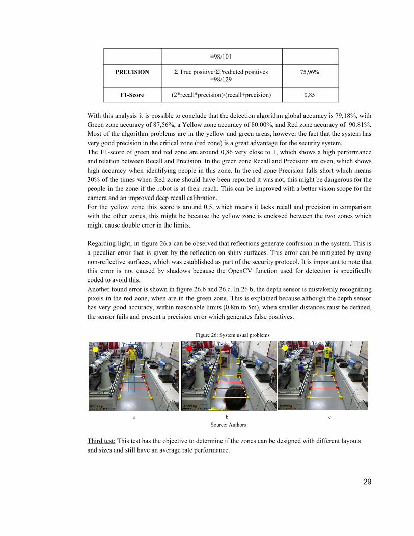
With this analysis it is possible to conclude that the detection algorithm global accuracy is 79,18%, with Green zone accuracy of 87,56%, a Yellow zone accuracy of 80.00%, and Red zone accuracy of 90.81%. Most of the algorithm problems are in the yellow and green areas, however the fact that the system has very good precision in the critical zone (red zone) is a great advantage for the security system. The F1-score of green and red zone are around 0,86 very close to 1, which shows a high performance and relation between Recall and Precision. In the green zone Recall and Precision are even, which shows high accuracy when identifying people in this zone. In the red zone Precision falls short which means 30% of the times when Red zone should have been reported it was not, this might be dangerous for the people in the zone if the robot is at their reach. This can be improved with a better vision scope for the camera and an improved deep recall calibration. For the yellow zone this score is around 0,5, which means it lacks recall and precision in comparison with the other zones, this might be because the yellow zone is enclosed between the two zones which might cause double error in the limits. Regarding light, in figure 26.a can be observed that reflections generate confusion in the system. This is a peculiar error that is given by the reflection on shiny surfaces. This error can be mitigated by using non-reflective surfaces, which was established as part of the security protocol. It is important to note that this error is not caused by shadows because the OpenCV function used for detection is specifically coded to avoid this. Another found error is shown in figure 26.b and 26.c. In 26.b, the depth sensor is mistakenly recognizing pixels in the red zone, when are in the green zone. This is explained because although the depth sensor has very good accuracy, within reasonable limits (0.8m to 5m), when smaller distances must be defined, the sensor fails and present a precision error which generates false positives.
Figure 26: System usual problems
a b c
Source: Authors
Third test: This test has the objective to determine if the zones can be designed with different layouts and sizes and still have an average rate performance.
29
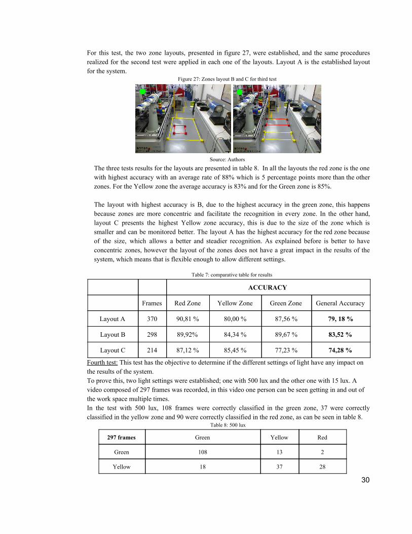
For this test, the two zone layouts, presented in figure 27, were established, and the same procedures realized for the second test were applied in each one of the layouts. Layout A is the established layout for the system.
Figure 27: Zones layout B and C for third test
Source: Authors
The three tests results for the layouts are presented in table 8. In all the layouts the red zone is the one with highest accuracy with an average rate of 88% which is 5 percentage points more than the other zones. For the Yellow zone the average accuracy is 83% and for the Green zone is 85%. The layout with highest accuracy is B, due to the highest accuracy in the green zone, this happens because zones are more concentric and facilitate the recognition in every zone. In the other hand, layout C presents the highest Yellow zone accuracy, this is due to the size of the zone which is smaller and can be monitored better. The layout A has the highest accuracy for the red zone because of the size, which allows a better and steadier recognition. As explained before is better to have concentric zones, however the layout of the zones does not have a great impact in the results of the system, which means that is flexible enough to allow different settings.
Table 7: comparative table for results
ACCURACY
Frames Red Zone Yellow Zone Green Zone General Accuracy
Layout A 370 90,81 % 80,00 % 87,56 % 79, 18 %
Layout B 298 89,92% 84,34 % 89,67 % 83,52 %
Layout C 214 87,12 % 85,45 % 77,23 % 74,28 %
Fourth test: This test has the objective to determine if the different settings of light have any impact on the results of the system. To prove this, two light settings were established; one with 500 lux and the other one with 15 lux. A video composed of 297 frames was recorded, in this video one person can be seen getting in and out of the work space multiple times. In the test with 500 lux, 108 frames were correctly classified in the green zone, 37 were correctly classified in the yellow zone and 90 were correctly classified in the red zone, as can be seen in table 8.
Table 8: 500 lux
297 frames Green Yellow Red
Green 108 13 2
Yellow 18 37 28
30

Red 0 1 90
ACCURACY (Σ True positive +ΣTrue negative)/ΣTotal =(108+37+90)/297
79,12 %
In the test with 15 lux, 75 frames were correctly classified in the green zone, 27 were correctly classified in the yellow zone and 61 were correctly classified in the red zone, as can be seen in table 9.
Table 9: 15 lux
217 frames Green Yellow Red
Green 75 18 2
Yellow 24 27 10
Red 0 0 61
ACCURACY (Σ True positive +ΣTrue negative)/ΣTotal =(75+27+610)/217
75,11 %
The accuracy of the system in both setting is around 75%, which means that although the light does affect the system it still has a good performance with a lot less luxes, which is a good indicator of the robustness of the system in terms of light. However as safety is the priority is recommendable to use all the light possible in the environment to ensure employees health.
6.5. Impact Measure To measure the consequences of the implementation of this safety system an economic approach is needed. It is important to note that this economic analysis is just for the safety system, assuming that the robot is already installed and working properly, and the computer power is already in place too. The system would cost around COP $6’369.000, as shown below.
Table 9: starting investment
Element Investment (COP)
Kinect $ 143,990
Base $ 15,000
Software $ 2,000,000
3 Engineer (160 man hour) $ 4,090,909
Installation $ 100,000 Transportation $ 20,000
Manpower Installation $30,000
Tests and delivery protocol $ 800,000 Copyright fees $ 300,000
Starting Investment $ 6,369,899 The software cost includes the algorithm programming as well as the user interface. The engineer hours is the cost for the specialized work of the project, including the parametrization of the safety zones according to the work space and the establishing of the communication with the robot system. The tests
31
and delivery protocol include the training and tests in place to let the system working accordingly. The Copyright fees (or the license) is the right to use the bought software in the workplace. According to [64], recyclers earn around $2’400.000 per year as they develop their task nowadays, but with the Motoman and the safety system these earnings may increase around 50% ($3’600.000), so with a rate of 1,18% EM, the cost-benefit of this system would be 1.03 with a payback of 21,01 months, a TIR of 2,0% and a NPV of COP $173.039. This means the safety system is not viable in the short term and as this cost gathers with the robotic system implementation is even more difficult to implement this type of collaborative environment in this particular task. In other industries, the system could help to increase earnings as accidents and interruptions decrease, also might improve the use of space as distances are reduced using the proposed protocols and algorithms. The social impact generated by this system lies in the dignity and safety of recyclers work. As seen in Section 6.2 recyclers are vulnerable to strange substances and non hygienic environments which could cause illness and contamination of their surroundings and, as shown before, the remuneration is really low. The project helps to decrease the time exposition to unhealthy environments and to avoid accidents and bad practices making their job more secure and increasing their life quality, however although this project shed some light to the recyclers situation and their profession, the issues are far more profound and require urgent legislation and district action.
7. CONCLUSIONS AND RECOMMENDATIONS
CONCLUSIONS
● The designed system is able to establish a collaborative human-robot environment by means of a vision algorithm enforcing safety in the workspace, establishing a clear security protocol for the picking task in plastic recycling, by interpreting and analyzing the norms and applying them in a real-life case study. This might be helpful for other researchers looking for the parametrization of collaborative environments in specific tasks.
● The system is able to recognize any kind of movement using affordable equipment and software that allows the flexibility and versatility required for SME. As a whole, the system is able to secure the workspace with an average accuracy of 79% under the specific layout and conditions of study.
● The zones creation algorithm has an average rate success of 78% in the three studied layouts, and can be used in other applications to create limits in detection applications.
● The recognition algorithm has a rate success of 73% in CTAI’s controlled environment. ● The behavior algorithm is capable to recognize intruders in every safety zone and to send signals to
the robot using ROS, for it to change its movements. However, it is not possible to test it in real life as MoveIt! does not support the speed modification while executing a trajectory (See section 6.3).
● The system proposed is considered level 4 and 6 of measures for risk reduction and ergonomic improvement, which means that it is assuring the collaborative environment (See Section 5.2).
● The system is not economically viable in the short term. However, although recyclers seem reluctant to robot implementation, they believe it could be useful and may consider it a job partner, ensuring a collaborative environment (See Section 6.2).
RECOMMENDATIONS
● The results analysis of the implemented questionnaires have some limitations because they are subjective and depend of cultural background, prior experiences with robots and personality. The resulting values should therefore be interpreted as a tool for comparison and not as absolute values. The questionnaires only offer a general view that is in constant change, as human perception changes
32
as well. Therefore, for future work, the authors recommend the implementation of more tests and questionnaires studying psychological and physiological responses in controlled simulations.
● For future works the authors recommend the use of two cameras or to position the kinect from the roof in the highest point possible, to encompass the whole area and avoid blind spots.
● For future works the authors recommend the use of light and sonorous signals to give the system more warnings and keep the workers aware of their surroundings.
● According to Código Sustantivo del Trabajo Art 230-235 employees that earn less than two minimum legal salaries have right to an endowment (clothes and footwear) appropriate to perform the assigned work, also according to OHSAS 8000 every worker must have protection equipment to reduce the impact of the labor. Conforming to these norms, authors recommend the procurement of safety elements as overalls and gloves to perform their work with care and dignity, and the redesign of the workstation of the recyclers to procure their safety and increase their quality of work and life as well.
8. GLOSSARY ● Algorithm: A set of mathematical instructions or rules that help to calculate the answer to a problem
[37]. ● Artificial vision: Automatic extraction, analysis and understanding of useful information from
images, developing theoretical and algorithmic basis to achieve automatic visual understanding [38]. ● Automation: The creation and application of technology to monitor and control the production and
delivery of products and services; the technique of making an apparatus, process or system operate automatically [39].
● Industrial robot: A manipulator designed to move materials, parts and tools, and perform a variety of programmed tasks in manufacturing and production settings [40].
● Industrial security/safety: Management of all operations and events within an industry for protecting its employees and assets by minimizing hazards, risks and accidents [41].
● Kinect: Gaming device developed by Microsoft that includes a RGB camera and a depth sensor. ● Motoman SDA10F: Dual arm robot suited for assembly, part transfer, machine tending, packaging
and other handling tasks that could only be done by people [35]. ● OpenCV library: Open Source Computer Vision Library, built to provide a common infrastructure
for computer vision applications. [42] ● RGB Camera: A camera capable of delivering images in the three basic color components (Red,
Green, Blue) [43]. ● Robot: A machine capable of carrying out a complex series of actions automatically, especially one
programmed by a computer. ● ROS-I:Robot Operating System Industrial, Open source project that extends the advanced
capabilities of ROS to manufacturing and robotics [2]. ● Sensor: A device which detects or measures a physical property and records, indicates, or otherwise
responds to it. REFERENCES [1] W. Macdougall, «Industries 4.0 Smart Manufacturing for the Future,» julio 2014. [On line]. Available:
https://www.gtai.de/GTAI/Content/EN/Invest/_SharedDocs/Downloads/GTAI/Brochures/Industries/industrie4.0-smart-manufacturing-for-the-future-en.pdf. [Last access: 30 September 2017]
[2] «Ros-Industrial,» [On line]. Available: http://rosindustrial.org/. [Last access: 15 September 2017]
33

[3] M. Seitz, «Qué países tienen más robots en sus fábricas y cuán cierto es que nos están robando los puestos de trabajo,» 17 Marzo 2017. [On line]. Available: http://www.bbc.com/mundo/noticias-39267567. [Last access: 15 September 2017]
[4] IFR, «World Robotics Report 2016,» 29 Septiembre 2016. [On line]. Available: https://ifr.org/ifr-press-releases/news/world-robotics-report-2016. [Last access: 30 September 2017]
[5] M. Bélanger-Barrette, «Robotiq,» 19 Agosto 2015. [On line]. Available: https://blog.robotiq.com/what-does-collaborative-robot-mean. [Last access: 30 September 2017]
[6] K. Pittman, «A History of Collaborative Robots: From Intelligent Lift Assists to Cobots,» 28 Octubre 2016. [On line]. Available: http://www.engineering.com/AdvancedManufacturing/ArticleID/13540/A-History-of-Collaborative-Robots-From-Intelligent-Lift-Assists-to-Cobots.aspx. [Last access: 15 September 2017]
[7] Universal Robots, «About Universal Robots - how we sold the first cobot,» 17 Mayo 2016. [On line]. Available: https://www.universal-robots.com/about-universal-robots/news-centre/history-of-the-cobots/. [Last access: 30 September 2017]
[8] J. Fryman y B. Matthias, «Safety of Industrial Robots: From Conventional to Collaborative Applications,» 2012.
[9] Universal Robots, «Universal Robots has reinvented industrial robotics with our Cobots,» 2012. [On line]. Available: https://www.youtube.com/watch?time_continue=45&v=UQj-1yZFEZI. [Last access: 30 September 2017]
[10] F. Tobe, «Why Co-Bots Will Be a Huge Innovation and Growth Driver for Robotics Industry,» 30 Diciembre 2015. [On line]. Available: https://spectrum.ieee.org/automaton/robotics/industrial-robots/collaborative-robots-innovation-growth-driver. [Last access: 15 September 2017]
[11] S. Kock, T. Vittor y B. Matthias, «Robot concept for scalable, flexible assembly automation: A technology study on a harmless dual-armed robot,» IEEE Xplore, 2011.
[12] P. Gahan, P. Evans y B. Sievewright, «Workplace Health and Safety, Business Productivity and Sustainability,» Julio 2014. [On line]. Available: http://newsroom.melbourne.edu/sites/newsroom.melbourne.edu/files/Workplace%20Health%20and%20Safety%20Report.pdf. [Last access: 30 September 2017]
[13] T. Hessman, «Safety is Productivity,» 14 Diciembre 2015. [On line]. Available: http://www.ehstoday.com/safety-leadership-conference-2015/safety-productivity. [Last access: 30 September 2017]
[14] M. Hägele, W. Schaaf y E. Helms, «Robot Assistants as Manual Workplaces: Effective Co-operation and Safety Aspects,» International Symposium on Robotics, vol. 33, 2002.
[15] A. Katwala, «Institution of Mechanical Engineers,» 7 Junio 2017. [On line]. Available: https://www.imeche.org/news/news-article/meet-the-cobots---giving-collaborative-robots-a-human-touch. [Último acceso: 5 Noviembre 2017].
[16] L. Cardona y A. Orejarena , «Día Mundial del Reciclaje: ¿cómo va Colombia?,» El Espectador, 18 Mayo 2016.
[17] D. S. Zarta, «Solo 26% de las botellas plásticas se recicla,» La República, 9 Marzo 2016.
[18] A. Tarantola, «Plastic-plucking robots are the future of recycling,» Engadget, vol. 21, p. Julio, 2017.
[19] Equipo editorial de Tecnología del Plástico, «En Colombia, el reciclaje de PET botella a botella tiene futuro,» Tecnología del Plástico, Agosto 2012.
[20] «Hasta $75.000 millones pagaría Postobón y Carbones del Cerrejón por obstruir facturas,» Dinero, Agosto 2017.
[21] «BIO Círculo,» [On line]. Available: http://www.biocirculo.com/reciclaje/. [Último acceso: 9 Noviembre 2017].
[22] P. Murphy, «Meet the cobots: humans and robots together on the factory floor,» Financial Times, 2017.
[23] B. Matthias, S. Kock y H. Jerregard, «Safety of collaborative industrial robots: Certification possibilities for a collaborative assembly robot concept,» IEEE Xplore, 2011.
[24] J. Koskinen, T. Heikkilä y T. Pulkkinen, «A Monitoring Concept for Co–operative Assembly Tasks».
[25] S. Sun, N. An, X. Zhao y M. Tan, «Human recognition for following robots with a Kinect sensor,» IEEE, 2017.
[26] G. Zhu, L. Zhang, P. Shen y J. Song, «An Online Continuous Human Action Recognition Algorithm Based on the Kinect Sensor,» MDPI, 2016.
[27] «Plastic-plucking robots are the future of recycling,» 21 Julio 2017. [On line]. Available: https://www.engadget.com/2017/07/21/a-better-way-to-recycle-plastics/. [Last access: 30 September 2017]
34

[28] N. Barrero y D. Galvis, «Designing a Framework to Give Perception Capabilities to an Industrial Robot for Waste Separation Tasks,» Pontificia Universidad Javeriana, 2017.
[29] C. Céspedes y A. Pinzón, «Sistema de control teleoperado mediante un sensor kinect para un robot Motoman Yaskawa,» Pontificia Universidad JAveriana, 2016.
[30] «ISO 10218-1:2011,» 2011. [On line]. Available: https://www.iso.org/standard/51330.html. [Last access: 30 September 2017]
[31] R. N. Shea, «Robot Safety Standard Update,» Orlando World Marriott Center, Orlando, Florida USA, 2013.
[32] «ISO/TS 15066:2016,» 2016. [On line]. Available: https://www.iso.org/standard/62996.html. [Last access: 30 September 2017]
[33] «ISO 10218-2:2011,» 2011. [On line]. Available: https://www.iso.org/standard/41571.html. [Last access: 30 September 2017]
[34] L. Cardona y A. Orejarena, «Día Mundial del Reciclaje: ¿cómo va Colombia?,» 18 Mayo 2016. [On line]. Available: https://www.elespectador.com/noticias/nacional/dia-mundial-del-reciclaje-va-colombia-articulo-633078. [Last access: 23 September 2017]
[35] Yaskawa, Technical Specifications SDA10F, 2017.
[36] P. Satyavolu y R. Brown, «A HUMAN, A BOT, AND A MANUFACTURING SHOP: WELCOME TO THE FUTURE WORKPLACE,» 18 Julio 2017. [On line]. Available: www.machinedesign.com. [Last access: 30 September 2017]
[37] «Cambridge Dictionary,» [On line]. Available: http://dictionary.cambridge.org. [Last access: 30 September 2017]
[38] «BMVA,» [On line]. Available: http://www.bmva.org. [Last access: 30 September 2017]
[39] «ISA,» [On line]. Available: https://www.isa.org. [Last access: 30 September 2017]
[40] «RobotWorx,» [On line]. Available: https://www.robots.com. [Last access: 30 September 2017].
[41] «Safeopedia,» [On line]. Available: https://www.safeopedia.com/definition/1052/industrial-safety. [Last access: 30 September 2017].
[42] «OpenCV,» [On line]. Available: http://opencv.org/. [Last access: 30 September 2017].
[43] E. Britanica, «Polyethylene terephthalate (PET or PETE),» [On line]. Available: https://www.britannica.com/science/polyethylene- terephthalate. [Last access: 30 September 2017].
[44] «National Instruments,» [On line]. Available: http://digital.ni.com/public.nsf/allkb/46BE3912D75112C58625652C005B8422. [Last access: 30 September 2017].
[45] A. Zanchettin, N. Ceriani , P. Rocco, H. Ding y B. Matthias, «Safety in Human-Robot Collaborative Manufacturing Environments: Metrics and Control,» IEEE, 2016.
[46] J. Marvel, «Performance Metrics of Speed and Separation Monitoring in Shared Workspaces,» IEEE, 2013.
[47] C. Tonelo, A. Moreira y G. Veiga, «Evaluation of sensors and algorithms for person detection for personal robots,» IEEE, 2013.
[48] «Morningstar Advisor,» [On line]. Available: http://www.morningstar.com/advisor/t/120662396/global-waste-sorting-robots-market-analysis-technologies-forecasts-to-2021-research-and-markets.htm. [Last access: 1 November 2017]
[49] T. Ciric, Z. Cojbasic, D. Ristic-Durrant, V. Nikolic, M. Ciric, M. Simonovic, I. Pavlovic «Thermal vision based intelligent system for human detection and tracking in mobile robot control system,» Thermal science, 2016
[50] E. Fotladis, M. Garzón, A. Barrientos «Human detection from a mobile robot using fusion laser and vision information,» Sensors, 2013.
[51] K. Misu, J. Miura «Specific person tracking using 3D LIDAR and ESPAR antenna for mobile service robots,» Toyohashi University, 2015.
[52] Occupational Safety and Health Administration, United States Department of Labor. Available:https://www.osha.gov/pls/imis/accidentsearch.search?sic=&sicgroup=&naics=&acc_description=&acc_abstract=&acc_keyword=%22Robot%22&inspnr=&fatal=&officetype=&office=&startmonth=&startday=&startyear=&endmonth=&endday=&endyear=&keyword_list=on&p_start=0&p_finish=20&p_sort=&p_desc=DESC&p_direction=Next&p_show=20 [Las acces: 16 February 2018]
[53] Tonelo. C, Moreira. A, Veiga. G. «Evaluation of sensors and algorithms for person detection for personal robots» Universidad do Porto, 2013.
[54] Wang. L, Schmidt. B, Nee. A. «Vision-guided active collision avoidance for human-robot collaborations» 2013
35
[55] W. A. Hernandez Martinez, L. J. Patiño Arevalo. «Selección y clasicación de piezas mediante visión de máquina utilizando un robot industrial» . Apr 2016, date retrieved 08-02-2018. [Online]. Available: http://hdl.handle.net/10185/18728
[56] G. Garzón, A. López. «Cortinas ópticas y Kinect, sistema de seguridad para celda robotizada» Pontificia Universidad Javeriana, 2016
[57] «ISO/TS 13849» 2016. [On line]. Available: hhttps://www.iso.org/standard/69883.html. [Last access: June 11 2018]
[58] «Yaskawa»[On line]. Available: http://cdn2.hubspot.net/hubfs/366775/downloads/documentation/156402-1CD.pdf?t=1468601845515 [Last access: march 5 2018]
[59] P. Lazota, T. Fong, J. Shah. «A Survey of Methods for Safe Human-Robot Interaction». [On line]. Available:http://interactive.mit.edu/sites/default/files/documents/2300000052-Lasota-Vol5-ROB-052.pdf[Last access: april 1 2018]
[60] Bartneck, C., Croft, E., & Kulic, D. (2009). Measurement instruments for the anthropomorphism, animacy, likeability, perceived intelligence, and perceived safety of robots. International Journal of Social Robotics, 1(1), 71-81. [On line]. Available:http://www.bartneck.de/publications/2009/measurementInstrumentsRobots/[Last access: May 1 2018]
[61] Rosebrock. A. «Basic motion detection and tracking with Python and OpenCV». [On line]. Available:https://www.pyimagesearch.com/2015/05/25/basic-motion-detection-and-tracking-with-python-and-opencv[Last access: June 1 2018]
[62] «Alcaldía de Bogotá». [On line]. Available: http://www.alcaldiabogota.gov.co/sisjur/normas/Norma1.jsp?i=33104. [Last access: June 1 2018]
[63] «Yaskawa». [On line]. Available: https://cdn2.hubspot.net/hubfs/366775/downloads/documentation/171483-1CD.pdf?t=1469555590506 [Last access: June 20 2018]
[64] «Microsoft’s Kinect Specification». [On line]. Available: https://msdn.microsoft.com/en-us/library/hh438998.aspx[Last access: march 20 de 2018]
[65] «Morphological Transformations». [On line]. Available: https://docs.opencv.org/3.1.0/d9/d61/tutorial_py_morphological_ops.htm [Last access: may 20 de 2018]
[66] G. Belingardi, S. Heydaryan, P. Chiabert. «Application of speed and separation monitoring method in human robot collaboration: industrial case study». [On line]. Available https://www.iim.ftn.uns.ac.rs/is17/papers/17.pdf [Last access: march 30 2018]
[67] O. Görnemann. «Mitos y realidades ISO/TS15066». [On line]. Available:http://www.fundacentro.gov.br/Arquivos/sis/EventoPortal/AnexoPalestraEvento/05_ISO%20TS%2015066_ES.pdf [Last access: march 30 2018]
[68] Marvel. J, Norcross R. «Implementing speed and separation monitoring in collaborative robot workcells».[On line]. Available: https://ws680.nist.gov/publication/get_pdf.cfm?pub_id=914783. [Last access: april 30 2018]
[69] GoBees. «Conceptos teóricos» .[On line]. Available: http://go-bees.readthedocs.io/es/develop/documentacion/3_ConceptosTeoricos.html. [Last access: april 30 2018]
[70] «Motion Analysis and Object Tracking». [On line]. Available:
https://docs.opencv.org/3.0-beta/modules/video/doc/motion_analysis_and_object_tracking.html?highlight=createbackgroundsubtractormog#createbackgroundsubtractormog [Last access: may 20 2018]
[71] «MoveIt! Time Parameterization». [On line]. Available: http://docs.ros.org/kinetic/api/moveit_tutorials/html/doc/time_parameterization/time_parameterization_tutorial.html. [Last access: june 20 2018]
[72] «MoveIt! Concepts». [On line]. Available: http://moveit.ros.org/documentation/concepts/. [Last access: june 20 de 2018]
[73] C.Zelada. «Evaluación de modelos de clasificación». [On line]. Available: https://rpubs.com/chzelada/275494 [Last access: july 1 2018]
[74] GitHub.«Confusion Matrix». [On line]. Available: https://rasbt.github.io/mlxtend/user_guide/evaluate/confusion_matrix/ [Last access: july 28 2018]
[75] Data School. «Simple guide to confusion matrix terminology». [On line]. Available: https://www.dataschool.io/simple-guide-to-confusion-matrix-terminology/[Last access: july 28 2018]
36