human-supervised control of the atlas humanoid robot for traversing...
TRANSCRIPT

Human-Supervised Control of the ATLAS Humanoid Robot
for Traversing Doors
Nandan Banerjee1, Xianchao Long1, Ruixiang Du1, Felipe Polido2, Siyuan Feng2,
Christopher G. Atkeson2, Michael Gennert1, and Taskin Padir1
Abstract— Door traversal is generally a trivial task for humanbeings but particularly challenging for humanoid robots. Thispaper describes a holistic approach for a full-sized humanoidrobot to traverse through a door in an outdoor unstructuredenvironment as specified by the requirements of the DARPARobotics Challenge. Door traversal can be broken down intofour sub-tasks; door detection, walk to the door, door opening,and walk through the door. These topics are covered in detailalong with the approaches used for step planning and motionplanning. The approach presented in this paper can be furtherextended to a wide range of door types and configurations.
I. INTRODUCTION
The DARPA Robotics Challenge (DRC) is aimed at ad-
vancing robotic technologies to assist humans in respond-
ing to natural and man-made disasters [1]. These systems
have to be highly adaptable in order to robustly operate in
unstructured and possibly chaotic environments, they also
must handle severe communication degradation, and be able
to manipulate their environment to accomplish critical goals.
This paper presents our approach to performing the door
task in the DRC Finals with the Boston Dynamics Atlas
humanoid robot. Atlas has 30 Degrees of Freedom (DoF),
weights approximately 180Kg, and stands at 1.80 meters
tall (Fig. 1). Its lower limbs, torso and shoulders are com-
posed of hydraulic joints, while the neck and forearms are
electric. The robot features two Robotiq 3-finger hands as
end-effectors, and it has a Carnegie Robotics Multisense
SL for perception. The Multisense SL features a camera
stereo pair and a spinning Hokuyo UTM-30LX-EW LIDAR
as two complementary sources of point-cloud information.
Lastly, the robot also includes a battery system and wireless
communication to operate without a tether or belay. Beyond
the physical hardware, for offline and parallel testing, the use
of a simulation environment in Gazebo was utilized.
We define the door traversal problem in the context of the
DRC as a standard door not exceeding dimensions of 36”
by 82” with a lever handle. Furthermore it is assumed the
door has no significant deformations or holes, i.e., the door
is solid. However, the exact door type would not be revealed
until DRC Finals take place. Therefore, the door handle can
be either on the left or right and the door can be opened
by either pulling or pushing. Our method has to be feasible
enough to deal with all these kinds of door.
The door traversal problem for robots has been the focus
of many research studies. Initially, researchers mainly dealt
*N. Banerjee and X. Long contributed equally to this work1Robotics Engineering, Worcester Polytechnic Institute2Robotics Institute, Carnegie Mellon University
Fig. 1: The upgraded Atlas Humanoid Robot built by Boston Dynamics.
with this problem with wheeled robots [2] [3]. However,
for wheeled robots the interaction forces between the robot
and the door have much less influence as the platforms
are statically stable. Only in the last few years have re-
searchers started to tackle door traversal using humanoid
robots. Proposed methods include using a systematic touch
scheme to grasp and turn the door knob [4], combining vision
and tactile sensing to open the door [5], and stabilizing
the robot against the reactive force of a door [6]. These
methods provide insights into the door traversal problem
but do not account for the wide range of conditions in an
outdoor environment. Because of not considering outdoor
conditions, our team failed on this task in the DRC Trails [7].
The strong wind which we never anticipated shut the door
closed numerous times after the robot had opened it and was
preparing to adjust its position to get through.
In this paper we propose a method for robust humanoid
door traversal that accounts for door detection in an outdoor
unstructured environment and high DoF motion planning.
This paper is organized as follows: In Section II, we
introduce our approach to humanoid door traversal. In Sec-
tion III, we present how the main perception problem of
door detection is addressed with both an automatic method
and a user-aided method. In Section IV, we illustrate the
work in motion planning we have done to make our Atlas
robot perform various of manipulations tasks. In Section V,
we show the performance of our methods. Lastly, Section VI
concludes our presented work and discusses possible areas
for future research.
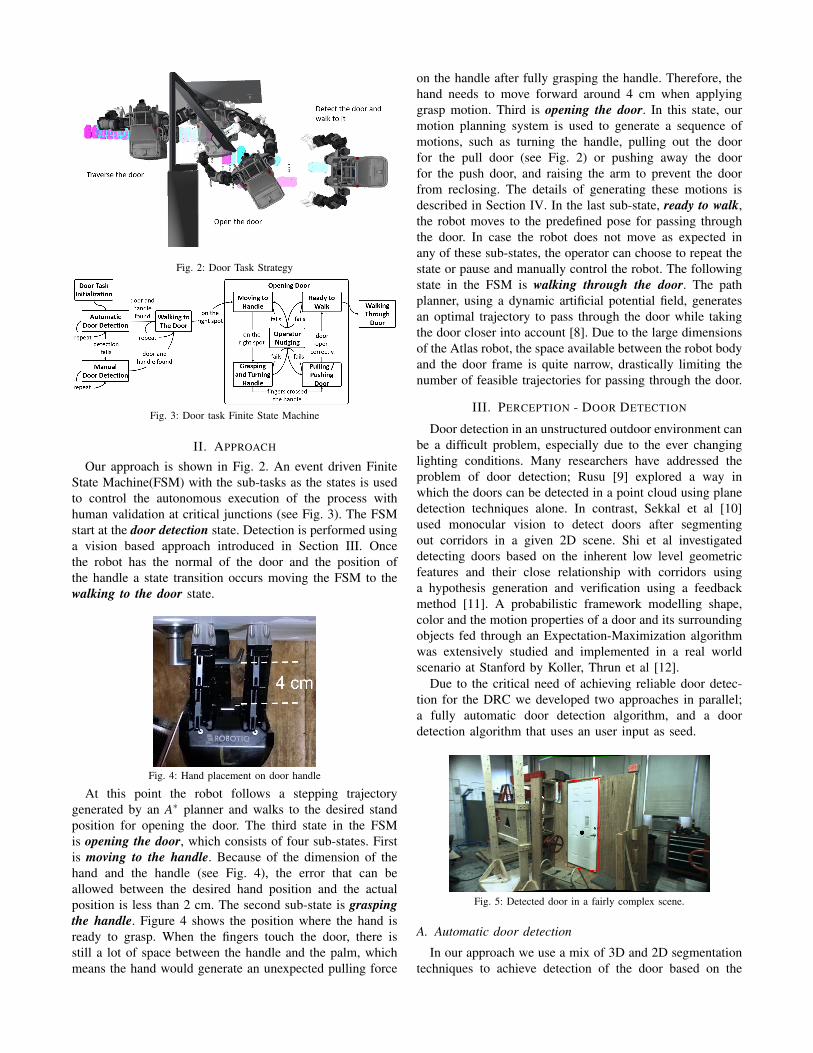
Fig. 2: Door Task Strategy
Fig. 3: Door task Finite State Machine
II. APPROACH
Our approach is shown in Fig. 2. An event driven Finite
State Machine(FSM) with the sub-tasks as the states is used
to control the autonomous execution of the process with
human validation at critical junctions (see Fig. 3). The FSM
start at the door detection state. Detection is performed using
a vision based approach introduced in Section III. Once
the robot has the normal of the door and the position of
the handle a state transition occurs moving the FSM to the
walking to the door state.
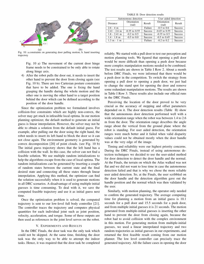
Fig. 4: Hand placement on door handle
At this point the robot follows a stepping trajectory
generated by an A∗ planner and walks to the desired stand
position for opening the door. The third state in the FSM
is opening the door, which consists of four sub-states. First
is moving to the handle. Because of the dimension of the
hand and the handle (see Fig. 4), the error that can be
allowed between the desired hand position and the actual
position is less than 2 cm. The second sub-state is grasping
the handle. Figure 4 shows the position where the hand is
ready to grasp. When the fingers touch the door, there is
still a lot of space between the handle and the palm, which
means the hand would generate an unexpected pulling force
on the handle after fully grasping the handle. Therefore, the
hand needs to move forward around 4 cm when applying
grasp motion. Third is opening the door. In this state, our
motion planning system is used to generate a sequence of
motions, such as turning the handle, pulling out the door
for the pull door (see Fig. 2) or pushing away the door
for the push door, and raising the arm to prevent the door
from reclosing. The details of generating these motions is
described in Section IV. In the last sub-state, ready to walk,
the robot moves to the predefined pose for passing through
the door. In case the robot does not move as expected in
any of these sub-states, the operator can choose to repeat the
state or pause and manually control the robot. The following
state in the FSM is walking through the door. The path
planner, using a dynamic artificial potential field, generates
an optimal trajectory to pass through the door while taking
the door closer into account [8]. Due to the large dimensions
of the Atlas robot, the space available between the robot body
and the door frame is quite narrow, drastically limiting the
number of feasible trajectories for passing through the door.
III. PERCEPTION - DOOR DETECTION
Door detection in an unstructured outdoor environment can
be a difficult problem, especially due to the ever changing
lighting conditions. Many researchers have addressed the
problem of door detection; Rusu [9] explored a way in
which the doors can be detected in a point cloud using plane
detection techniques alone. In contrast, Sekkal et al [10]
used monocular vision to detect doors after segmenting
out corridors in a given 2D scene. Shi et al investigated
detecting doors based on the inherent low level geometric
features and their close relationship with corridors using
a hypothesis generation and verification using a feedback
method [11]. A probabilistic framework modelling shape,
color and the motion properties of a door and its surrounding
objects fed through an Expectation-Maximization algorithm
was extensively studied and implemented in a real world
scenario at Stanford by Koller, Thrun et al [12].
Due to the critical need of achieving reliable door detec-
tion for the DRC we developed two approaches in parallel;
a fully automatic door detection algorithm, and a door
detection algorithm that uses an user input as seed.
Fig. 5: Detected door in a fairly complex scene.
A. Automatic door detection
In our approach we use a mix of 3D and 2D segmentation
techniques to achieve detection of the door based on the

geometric features of doors. A couple of assumptions are
made: First, the disparity values obtained within the door
section using the Multisense should be sufficiently reliable.
We define a reliable disparity as a disparity where if the
points are reprojected in 3D space, the distance for any point
of the door is 5 cm away from the door plane. Second, the
color of the handle will be significantly different from that
of the door. The detection is done based purely on the stereo
data.
Let P ∈ RP be a vector containing two vectors P2D and
P3D where RP is the set of all Ps for a particular image. Let
P2D =[
u v]T
be the pixel coordinates in the 2D image.
Let P3D =[
x y z]T
be the coordinates in the 3D task
space w.r.t the camera frame for the corresponding 2D image
pixel denoted by P2D.
P =[
P2D P3D
]T(1)
Let P1,P2 ∈ RP and SP be a set of P ∈ RP where P2D lie
in the line joining P1/2D and P2/2D. Let D represent a door
candidate containing P1,P2,SP. D is given by -
D =[
P1 P2 SP
]T(2)
For D to belong to a class of DRC doors,
• ∀P, where P ∈ SP, and a, b ∈ R3, (a−P3D) ·b = 0
• 80 cm ≤ || P1/3D −P2/3D ||2 ≤ 100 cm
The general idea behind the automatic door detection
algorithm is to segment out parallel vertical lines, find the
perpendicular distance between them and accept those lines
which have a distance of the door width between them.
The first step consists of image filtering. Histogram equal-
isation is performed to increase the contrast of the image,
which facilitates edge detection. Then a bilateral filter is
applied to smooth the image. Next, the edges are detected
using a Canny edge detector. Lastly, a Probabilistic Hough
Transform is applied over the resulting image to find lines.
By checking the line slopes, only the vertical lines which
have a pixel length greater than a threshold determined
experimentally are kept. Lines are grouped into pairs to form
a door candidate. Line pairs that have a pixel distance of
less than 60 pixels (also determined experimentally) are also
eliminated which reduces the search space but compromises
on the detection distance.
At this point the entire image is reprojected in 3D. The
line equations for the grouped line pairs are found using
RANdom SAmple Consensus (RANSAC). Pairs that have
a perpendicular distance of 90 ± 10 cm are kept and the
rest are discarded. To reduce redundant door pairs due to
inaccuracies in line detection, door pairs that have the same
line equations are merged together. The door pairs are then
validated by checking that a solid plane exists in between the
two door lines. This is done by taking two diagonals in the
door, sampling points on them in the 2D image and checking
to see if their 3D counterparts fall on the same plane or not.
If not, then the door line pair is rejected, else it is stored as a
door. The door plane normal is found by performing a cross
product between the line joining the two door edges and any
one door edge.
Fig. 7: Handle detection in a complex scene from Fig. 5.
In the second phase of the algorithm handle detection
is done based on the assumption that the handle is of a
significantly different color than the door:
• The mean and standard deviation of the pixels in the
image space inside the door region detected earlier are
found.
• Connected Component Analysis (CCA) is used to grow
the region which corresponds to the pixel value within
the range µ −σ and µ +σ .
• Based on prior knowledge that the handle is on the left
or the right hand side, a region is selected correspond-
ingly to exclude the central part of the door.
• In that selected region, the region which is not white
starting from the bottom and exceeds a certain contour
area threshold (“hard”) is selected as the door handle.
Finally, the entire algorithm is repeated over a window
of 10 frames. Detections from every frame is recorded. At
Fig. 6: First row shows detected doors at various perspectives. Second row shows the color based handle segmentation by searching within the detecteddoor.

the end of ten iterations, the detection with the maximum
occurrence is selected as the door (Fig. 5 and Fig. 7(b)).
B. User-aided door detection
The general concept for user-aided door detection is that
the user supplies a seed either in 3D or in a 2D perspective
which is then used to determine the position of the handle
and the normal from the door. Our approach has the user drag
the mouse over the latest 2D image from the Multisense,
marking the position of the handle. We call each of these
2D user seeds scribbles. In this method, the user scribbles
on the door handle and based on the knowledge of where
the door handle is, i.e. on the right or on the left of the door,
points offset on the side of the seeded point is sampled and
a plane is fitted over those points. This provides the handle
point (user seed) and the normal to the door which coupled
with the knowledge of the side where the handle gives us
the door estimate.
IV. MANIPULATION - MOTION PLANNING
In order to reliably complete manipulation tasks with
a humanoid robot it is important to generate end-effector
trajectories that maintain several constraints (like Center of
Mass (CoM) over the polygon of support and collision-free
motions) simultaneously. One approach is to use sample-
based search algorithm, such as rapidly exploring random
trees (RRT) [13] [14] [15], which can efficiently find a feasi-
ble path in the search space. This method is probabilistically
complete. However, searching in high DoF configuration
space and performing post-processing such as smoothing is
computationally intensive and time consuming.
Another category is optimization-based algorithms, such
as CHOMP [16], STOMP [17] and TrajOpt [18], which
can generate a path from an initial trajectory that may
be in-collision or dynamically infeasible. The result of the
trajectory optimization problem can be obtained in a short
period of time, even for a high dimensionality problem. But
challenges for trajectory optimization are its sensitivity to the
choice of initial guesses and getting stuck in local optima.
Since computation time is a high priority consideration in
the DRC, and TrajOpt has the best speed performance in
the benchmark test compared with other optimization-base
algorithms, we decided to modify TrajOpt as our motion
planning library and set up proper costs and constraints for
our Atlas humanoid robot. The way we deal with the initial
guess issue will be described as well.
For the manipulation tasks, the desired Cartesian motions
for the robot are specified, such as, foot position, hand
position and CoM location. The motion planning optimizer
formulates these motions as its costs and constraints, and
computes a trajectory represented by the joints states at a
set of waypoints. The general formulation of the optimizer
is the following :
minx
f (x)
s.t. gi(x)≥ 0, i = 1,2, ...,nieq
h j(x) = 0, j = 1,2, ...,neq
(3)
where f , gi and h j are scalar functions.
For our Atlas motion planning optimiser, we involve only
kinematics and represent the trajectory as a sequence of T
waypoints. The optimization variable x in (3) is of the form
x = q1:T , where qt ∈ ℜK describes the joint configuration at
the t-th time step for a system with K DoF. The cost function
f (x) can be written as:
f (q1:T ) =T
∑t=1
((qt+1 −qt)T Q1(qt+1 −qt)+
(qt −qnorm)T Q2(qt −qnorm)+dT
∆Q3d∆)
(4)
where Q1,Q2,Q3� 0, qnorm represents a nominal posture.
These quadratic cost terms are a penalization of the weighted
sum on the joint displacements between the waypoints,
posture error in joint space and posture error in Cartesian
space. The first term can limit the movement of the robot
and smooth the trajectory. The second term is used to push
joints to specific values when all the constraints have been
met. As similar as the second term, the third term is used to
push links to specific positions and orientations.
Fig. 8: Transforms and coordinate frames involved in computing the distanced∆. The current end-effector frame is C1 and the hand pose for graspinghandle is C′
1
The posture error in Cartesian space can be obtained by
calculating the distance d∆ from a given configuration to a
task space region introduced in [19]. For example, in Fig. 8,
the end-effector frame C1 defined in our Atlas model is on the
wrist. We generate a end-effector frame C2 for representing
the pose of the object held by the hand by setting an offset
transform T 12 . The desired grasp location C3 is near the door
handle. We expect to generate a trajectory that can lead the
robot end-effector to reach the desired grasping location .
Thus, the distance d∆ means the displacement between C2
and C3, which can be computed by converting the transform
T 32 (5) into a 6× 1 displacement vector from the origin of
the coordinate of C3 by (5).
T 32 = T 3
0 ∗T 02 = (T 0
3 )−1 ∗T 0
1 ∗T 12 = (T 0
3 )−1 ∗T 0
1 ∗ (T 21 )
−1
=
∣
∣
∣
∣
R t
0 1
∣
∣
∣
∣

TABLE I: Performance of Our Approaches for Both Types of Door
DoorDetection
Walking to the Door Opening the DoorWalking through
the DoorTotal
Pull DoorSuccessful Rate 87.5% 100% 85% 90% 82%
Time 20.5splanning step:20.8smoving:41s
an initial guess(4 times):40.4smultiple initial guess:21smoving:111s
124.2s 9min23s
Push Door(Including
DRC Finals)
Successful Rate 96% 100% 95% 92% 91%
Time 19.6splanning step:13.4smoving:33s
an initial guess(2 times):31smoving:117s
116.5s 7min40s
where R is the rotation matrix and t is the translation vector.
d∆ =
t
atan2(R32,R33)−asin(R31)
atan2(R21,R11)
(5)
where Rmn is an element in the row m and column n.
The constraints for the optimization problem include:
• Joint limits constraint. These can be written as q−Q− >0, and Q+−q > 0, where Q is the set of reachable joint
values, Q+ is the maximum value of Q, and Q− is the
minimum value.
• Joint posture constraint, which is represented as q−qd =0. This constraint can lock the joint in some specific
value qd at some time steps.
• Cartesian posture constraint. This constraint
can be established by setting the posture error
diag(c1,c2, ...,c6)d∆ = 0. We can release some position
and orientation constraints through setting the related
element in diag(c1,c2, ...,c6) to 0.
• CoM constraint. The horizontal projection of the CoM
is desired to be on the support convex polygon between
two feet. The support polygon can be represented as a
intersection of k half planes,
aixCoM +biyCoM + ci ≤ 0, i = 1,2,3, ...,n
where xCoM and yCoM are the location of the CoM
projection, which can be computed given the robot
posture q.
• Collision avoidance constraint. Generating a collision
free trajectory is one of the most important feature
for the motion planner. But it is difficult to formulate
collision constraint in a closed form for the optimization
motion planning. We use the method which is intro-
duced in [18] to set up the collision constraints. The
advantage of the method is that it can not only check
for discrete collisions in each step but also integrate
continuous-time collision avoidance constraints.
Therefore, to generate feasible motion for our Atlas robot,
a variety of costs and constraints are set, such as joint
displacement costs, knee joint and back joints nominal value
costs, pelvis height and orientation costs, torso orientation
costs, shoulder torque cost, joint limits constraints, self-
collision constraints, environment collision avoidance con-
straints, both feet position and orientation constraints, and
CoM constraints. These are the general costs and constraints,
while according to the requirements of each tasks, some
particular costs and constraints also need to be added. For
push door, two trajectories need to be planned, which are
approaching the door handle and turning the door handle.
For a pull door, among two previous motions, the robot also
has to pull the door back and block the door with the other
hand.
1) A Cartesian posture constraint is added on the final step
of the trajectory for approaching the door handle. The
parameters of the constraint are the desired position
and orientation for the robot end effector to grasp the
handle (see Fig. 8), which are computed based on
the handle configuration detected by the robot vision
system.
Fig. 9: constraints on generating door handle turning motion
2) During the handle turning motion, the handle hinge is
not translating. There is only the rotation movement on
the hinge. Two Cartesian posture constraints are added
on the trajectory. First is the final step constraint. The
offset transform T 12 is from grasper frame C1 to the
current handle hinge frame C2, while the target frame
C3 is the current handle hinge frame rotating around
80o.(see Fig. 9) The second one is a whole trajectory
posture constraint, which limits the movement of the
current handle hinge frame and only allows it to
move along the hinge axis through setting the coef-
ficients of the posture constraints diag(c1,c2, ...,c6) as
diag(1,1,1,1,0,1). When the handle is held in the
grasper, the transform T 12 can be obtained by adding a
minor offset to the current gripper frame configuration
calculating by forward kinematics.
3) Similar to the handle turning motion, opening the door
also has a rotation-only point which is the door hinge.
Hence, the offset transform T 12 can be calculated using
the width of the door, and the target frame C3 is the
current door hinge frame C2 rotating around 40o.(see
(a) (b)Fig. 10: a.constraints on generating door pulling motion; b. hand insertingtrajectory
Fig. 10 a) The movement of the current door hinge
frame needs to be constrained to be only able to rotate
along hinge axis.
4) After the robot pulls the door out, it needs to insert the
other hand to prevent the door from closing again (see
Fig. 10 b). There are two Cartesian posture constraints
that have to be added. The one is fixing the hand
grasping the handle during the whole motion and the
other one is moving the other hand to a target position
behind the door which can be defined according to the
position of the door handle.
Since the optimization problem we formulated involves
collision-free constraints which are highly non-convex, the
solver may get stuck in infeasible local optima. In our motion
planning optimizer, the default method to generate an initial
guess is linear interpolation. However, the solver may not be
able to obtain a solution from the default initial guess. For
example, after pulling out the door using the right hand, the
robot needs to insert its left hand to block the door so it can
not close again. The environment geometry is generated by
convex decomposition [20] of point clouds. (see Fig. 10 b)
The initial guess trajectory shows that the left hand has a
collision with the wall. In this case, the solver can not find a
feasible solution. We use multiple random initializations to
help the algorithms escape from the case of local optima. The
random initializations can be generated by inserting a couple
of random states between the current state and the final
desired state and connecting all these states through linear
interpolation. Applying this method, the optimizer can find
the solution successfully when it is used to generate motions
in all DRC scenarios. A disadvantage of using multiple initial
guesses is time consuming. To deal with it, we save the
computed feasible trajectory and use it as initial guess next
time.
Once the optimization problem is solved, the computed
trajectory is sent to our low-level full body controller [21].
The controller traces the trajectory and computes physical
quantities for each individual joint such as joint position,
velocity, acceleration, and torque. Some of these outputs are
then used as references in the joint level servos on the robot.
V. EXPERIMENTS AND RESULTS
In the DRC Finals, the door task was the only task which
could not be skipped. At the same time, finishing the door
task was the only way to be able to attempt the indoor
tasks. Hence, it was required that the door task be completed
TABLE II: Door detection results
Autonomous detection User aided detection
DistanceOrientation
(rad)Result
Orientation(rad)
Result
2.6 - 4 m - Failure -0.5 to 0.6 Success
2.41 - 2.6 m -0.35 to 0.55 Success -0.45 to 0.55 Success
1.8 - 2.41 m -0.2 to 0.5 Success -0.35 to 0.5 Success
1.4 - 1.8 m -0.5 to 0.0 Success -0.5 to 0.45 Success
1.3 m - 1 m - Failure -0.2 to 0.2 Success
reliably. We started with a pull door to test our perception and
motion planning tools. We figured that opening a pull door
would be more difficult than opening a push door because
more complex manipulation motions needed to be combined.
The test results are shown in Table I Row 2. About a month
before DRC Finals, we were informed that there would be
a push door in the competition. To switch the strategy from
opening a pull door to opening a push door, we just had
to change the stand spot for opening the door and remove
some redundant manipulation motions. The results are shown
in Table I Row 3. These results also include our official runs
in the DRC Finals.
Perceiving the location of the door proved to be very
crucial as the accuracy of stepping and offset parameters
depended on it. The door detection results (Table II) show
that the autonomous door detection performed well with a
wide orientation range when the robot was between 1.4 to 2.6
m from the door. The orientation range describes the angle
range about the vertical from the ground plane where the
robot is standing. For user aided detection, the orientation
ranges were much better and it failed when valid disparity
values could not be obtained mostly when the door handle
was at the very edge of the image.
Timing and reliability were our highest priority concerns.
During the DRC Finals, instead of using autonomous de-
tection techniques we decided to use the user-aided method
for door detection to detect the door handle and the normal.
At the Finals, the terrain on which the Atlas walked was not
flat and we did not want to lose time in case the autonomous
detection failed and that is why we chose the more reliable
user aided detection. So, at the Finals, the user scribbled on
the door handle and the detection algorithm gave out the
handle position and the normal which was then validated by
the user.
Similarly, with motion planning, the operator only needed
to confirm the generated trajectory. The average computing
time for planning a motion from an initial guess is 10.1
seconds for a pull door and 15.5 seconds for a push door,
and from multiple initial guesses it is 21 seconds. The motion
generated from multiple-initial guesses is inserting the other
hand to prevent the door from closing again, because the
robot had to avoid collision with the complex environment
in this motion. For generating motion from multiple-initial
guesses, we used a linear interpolated trajectory and two
random trajectories as initial guesses in our experiments, and
returned the first feasible result coming from our motion
planner. The low level controller can precisely trace the
generated trajectory. All the failure cases in opening the door
Fig. 11: Door traversal during the DRC Finals
were because the hand didn’t grasp the handle properly and
it slipped off the handle.
VI. CONCLUSION AND FUTURE WORK
We have presented our approach for executing the door
task as stated by the DRC Finals. The door traversal task
can be executed reliably in a wide range of unstructured
environments with the perception and motion planning algo-
rithms described above. We successfully completed the door
task on both the runs in the DRC Finals (see Fig. 11). We
were the only Atlas team that used motion planning to open
the door. Other Atlas teams pushed the handle down without
grasping it and utilized the self-opening mechanism of the
door at the DRC Finals to open it. This hitting motion is
very unreliable and cannot guarantee that the door would
be opened properly, and many teams had to try this multiple
times at the DRC Finals. Our strategy on the other hand pays
a penalty of a little under 20 seconds to finish the motion
planning computations and provides a much more robust and
reliable door opening motion. In the future, we plan to speed
up the motion planner through reuse of previously generated
trajectories as initial guesses. Moreover, since our current
motion planner only involves kinematic constraints, the low-
level controller has to follow the trajectory slowly to avoid
dynamic instability. Another area of research would be to
introduce key dynamic features into our motion planner so
robot trajectory execution can be faster.
ACKNOWLEDGEMENT
This work was sponsored by the Defense Advanced Re-
search Project Agency, DARPA Robotics Challenge Program
under Contract No. HR0011-14-C-0011. We also thank Perry
Franklin, Benzun Babu and the lab team for their support.
REFERENCES
[1] DARPA, “About the DARPA Robotics Challenge,” 2013 2013.[Online]. Available: http://theroboticschallenge.org/about
[2] W. Meeussen, M. Wise, S. Glaser, S. Chitta, C. McGann, P. Mihelich,E. Marder-Eppstein, M. Muja, V. Eruhimov, T. Foote, J. Hsu, R. Rusu,B. Marthi, G. Bradski, K. Konolige, B. Gerkey, and E. Berger,“Autonomous door opening and plugging in with a personal robot,” inRobotics and Automation (ICRA), 2010 IEEE International Conference
on, May 2010, pp. 729–736.
[3] S. Chitta, B. Cohen, and M. Likhachev, “Planning for autonomousdoor opening with a mobile manipulator,” in Robotics and Automation
(ICRA), 2010 IEEE International Conference on, May 2010, pp. 1799–1806.
[4] H. Arisumi, N. Kwak, and K. Yokoi, “Systematic touch scheme for ahumanoid robot to grasp a door knob,” in Robotics and Automation
(ICRA), 2011 IEEE International Conference on, May 2011, pp. 3324–3331.
[5] M. Prats, P. Sanz, and A. del Pobil, “Reliable non-prehensiledoor opening through the combination of vision, tactile and forcefeedback,” Autonomous Robots, vol. 29, no. 2, pp. 201–218, 2010.[Online]. Available: http://dx.doi.org/10.1007/s10514-010-9192-1
[6] H. Arisumi, J.-R. Chardonnet, and K. Yokoi, “Whole-body motionof a humanoid robot for passing through a door - opening a doorby impulsive force -,” in Intelligent Robots and Systems, 2009. IROS
2009. IEEE/RSJ International Conference on, Oct 2009, pp. 428–434.[7] M. DeDonato, V. Dimitrov, R. Du, R. Giovacchini, K. Knoedler,
X. Long, F. Polido, M. A. Gennert, T. Padr, S. Feng, H. Moriguchi,E. Whitman, X. Xinjilefu, and C. G. Atkeson, “Human-in-the-loopControl of a Humanoid Robot for Disaster Response: A Report fromthe DARPA Robotics Challenge Trials,” J. Field Robotics, vol. 32, pp.275–292, 2015.
[8] G. Digioia, H. Arisumi, and K. Yokoi, “Trajectory planner for ahumanoid robot passing through a door,” in Humanoid Robots, 2009.
Humanoids 2009. 9th IEEE-RAS International Conference on, Dec2009, pp. 134–141.
[9] R. B. Rusu, “Semantic 3D Object Maps for Everyday Manipulation inHuman Living Environments,” Artificial Intelligence (KI - Kuenstliche
Intelligenz), 2010 2010.[10] R. Sekkal, F. Pasteau, M. Babel, B. Brun, and I. Leplumey, “Simple
monocular door detection and tracking,” in Image Processing (ICIP),
2013 20th IEEE International Conference on, Sept 2013, pp. 3929–3933.
[11] W. Shi and J. Samarabandu, “Investigating the Performance of Cor-ridor and Door Detection Algorithms in Different Environments,” inInformation and Automation, 2006. ICIA 2006. International Confer-
ence on, Dec 2006, pp. 206–211.[12] D. Anguelov, D. Koller, E. Parker, and S. Thrun, “Detecting and
modeling doors with mobile robots,” in Robotics and Automation,
2004. Proceedings. ICRA ’04. 2004 IEEE International Conference
on, vol. 4, April 2004, pp. 3777–3784 Vol.4.[13] S. M. LaValle, Planning Algorithms. Cambridge, U.K.: Cambridge
University Press, 2006, available at http://planning.cs.uiuc.edu/.[14] J. Kuffner and S. LaValle, “RRT-connect: An efficient approach
to single-query path planning,” in Robotics and Automation, 2000.
Proceedings. ICRA ’00. IEEE International Conference on, vol. 2,2000, pp. 995–1001 vol.2.
[15] S. Karaman and E. Frazzoli, “Sampling-based Algorithms for OptimalMotion Planning,” International Journal of Robotics Research, vol. 30,no. 7, pp. 846–894, June 2011.
[16] N. Ratliff, M. Zucker, J. Bagnell, and S. Srinivasa, “CHOMP: Gradientoptimization techniques for efficient motion planning,” in Robotics and
Automation, 2009. ICRA ’09. IEEE International Conference on, May2009, pp. 489–494.
[17] M. Kalakrishnan, S. Chitta, E. Theodorou, P. Pastor, and S. Schaal,“STOMP: Stochastic trajectory optimization for motion planning,” inRobotics and Automation (ICRA), 2011 IEEE International Conference
on, May 2011, pp. 4569–4574.[18] J. Schulman, Y. Duan, J. Ho, A. Lee, I. Awwal, H. Bradlow, J. Pan,
S. Patil, K. Goldberg, and P. Abbeel, “Motion planning with sequentialconvex optimization and convex collision checking,” The International
Journal of Robotics Research, 2014.[19] D. Berenson, “Constrained Manipulation Planning,” Ph.D. dissertation,
Robotics Institute, Carnegie Mellon University, Pittsburgh, PA, May2011.
[20] K. Mamou and F. Ghorbel, “A simple and efficient approach for3D mesh approximate convex decomposition,” in Image Processing
(ICIP), 2009 16th IEEE International Conference on, Nov 2009, pp.3501–3504.
[21] S. Feng, E. Whitman, X. Xinjilefu, and C. G. Atkeson, “Optimization-based Full Body Control for the DARPA Robotics Challenge,” Journal
of Field Robotics, vol. 32, no. 2, pp. 293–312, 2015. [Online].Available: http://dx.doi.org/10.1002/rob.21559