humidity sensors: a review of materials and mechanismszhichen/publication/humidity-sensors... ·...
TRANSCRIPT

REVIEW
Copyright © 2005 American Scientific PublishersAll rights reservedPrinted in the United States of America
SENSOR LETTERSVol. 3, 274–295, 2005
Humidity Sensors: A Review ofMaterials and Mechanisms
Zhi Chen∗ and Chi LuDepartment of Electrical and Computer Engineering and Center for Nanoscale Science and Engineering,
University of Kentucky, Lexington, Kentucky 40506, USA
(Received: 22 July 2005. Accepted: 27 July 2005)
We have reviewed humidity sensors based on various materials for both relative and absolutehumidity, including ceramic, semiconducting, and polymer materials. In the majority of publications,there are few papers dealing with absolute humidity sensors, which have extensive applications inindustry. We reviewed extensively absolute humidity sensors in this article, which is unique com-paring with other reviews of humidity sensors. The electrical properties of humidity sensors suchas sensitivity, response time, and stability have been described in details for various materials anda considerable part of the review is focused on the sensing mechanisms. In addition, preparationand characterization of sensing materials are also described. For absolute humidity sensors, mirror-based dew-point sensors and solid-state Al2O3 moisture sensors have been described. As the majorproblem in Al2O3 moisture sensors, long-term instability, has been solved, -Al2O3 moisture sensorsmay have promising future in industry.
Keywords: Humidity Sensor, Mechanisms, Humidity-Sensing, Relative Humidity, AbsoluteHumidity, Dew Point, Frost Point.
CONTENTS
1. Introduction . . . . . . . . . . . . . . . . . . . . . . . . . . . . . . . . . 2742. Classification of Humidity Sensors . . . . . . . . . . . . . . . . . . 2753. Relative Humidity Sensors . . . . . . . . . . . . . . . . . . . . . . . 275
3.1. Ceramic Sensing Materials . . . . . . . . . . . . . . . . . . . . 2753.2. Semiconducting Sensing Materials . . . . . . . . . . . . . . . 2803.3. Polymer-Based Humidity Sensors . . . . . . . . . . . . . . . . 281
4. Absolute Humidity Sensors (Hygrometers) . . . . . . . . . . . . . 2864.1. Mirror-Based Dew/Frost Point Sensors (Hygrometers) . . . 2864.2. Aluminum Oxide Moisture Sensors . . . . . . . . . . . . . . . 289
5. Conclusions . . . . . . . . . . . . . . . . . . . . . . . . . . . . . . . . . 292References and Notes . . . . . . . . . . . . . . . . . . . . . . . . . . . 292
1. INTRODUCTION
Humidity sensors have gained increasing applicationsin industrial processing and environmental control.1 Formanufacturing highly sophisticated integrated circuits insemiconductor industry, humidity or moisture levels areconstantly monitored in wafer processing. There aremany domestic applications, such as intelligent control ofthe living environment in buildings, cooking control for
∗Corresponding author; E-mail: [email protected]
microwave ovens, and intelligent control of laundry etc.In automobile industry, humidity sensors are used in rear-window defoggers and motor assembly lines. In medicalfield, humidity sensors are used in respiratory equip-ment, sterilizers, incubators, pharmaceutical processing,and biological products. In agriculture, humidity sensorsare used for green-house air-conditioning, plantation pro-tection (dew prevention), soil moisture monitoring, andcereal storage. In general industry, humidity sensors areused for humidity control in chemical gas purification, dry-ers, ovens, film desiccation, paper and textile production,and food processing.In this paper, we aim to present extensive review of
research and development of humidity sensors for a widevariety of applications. Because applications in each fieldrequire different operating conditions, various types ofhumidity sensors based on a variety of sensing materi-als will be described. This paper is organized as follows.It begins with brief review of classification of humiditysensors based on types of sensing materials and detec-tion ranges (Section 2). Then the relative humidity sensorsbased on ceramic, semiconductor, and polymer materi-als will be discussed in Section 3. Absolute humiditysensors, which were not extensive studied but are found
274 Sensor Lett. 2005, Vol. 3, No. 4 1546-198X/2005/3/274/022 doi:10.1166/sl.2005.045

REVIEW
Chen and Lu Humidity Sensors: A Review of Materials and Mechanisms
wide-spread applications in many industrial fields, will bereviewed in Section 4.
2. CLASSIFICATION OFHUMIDITY SENSORS
Humidity measurement determines the amount of watervapor present in a gas that can be a mixture, such asair, or a pure gas, such as nitrogen or argon. Based onmeasurement techniques, the most commonly used unitsfor humidity measurement are Relative Humidity (RH),Dew/Frost point (D/F PT) and Parts Per Million (PPM).2
Relative Humidity (RH) is the ratio of the partial pressureof water vapor present in a gas to the saturation vaporpressure of the gas at a given temperature. RH is a func-tion of temperature, and thus it is a relative measurement.The RH measurement is expressed as a percentage. Dewpoint is the temperature (above 0 C) at which the watervapor in a gas condenses to liquid water. Frost point is thetemperature (below 0 C) at which the vapor condenses toice. D/F PT is a function of the pressure of the gas butis independent of temperature and is therefore defined asabsolute humidity measurement. Parts Per Million (PPM)represents water vapor content by volume fraction (PPMv)or, if multiplied by the ratio of the molecular weight ofwater to that of air, as PPMw. PPM is also an absolutemeasurement. Although this measurement unit is more dif-ficult to conceive, it has extensive applications in industryespecially for trace moisture measurement.Figure 1 shows the correlation among Relative Humid-
ity (RH), Parts Per Million by volume (PPMv), and theDew/Frost Point (D/F PT). RH measurement covers higherhumidity range, PPMv covers lower humidity range, and
Zhi Chen received his B.S. degree in 1984 and M.S. degree in 1987 in electrical engineeringfrom University of Electronic Science and Technology, Chengdu, China. He obtained aPh.D. degree in electrical engineering from University of Illinois at Urbana-Champaign in1999. He is currently an associate professor with Department of Electrical Engineeringand the associate director of Center for Nanoscale Science and Engineering, Universityof Kentucky. He is a senior member of IEEE and won the National Science FoundationCAREER Award in 2001. His research interests include micro/nano fabrication, nanoscaledevices and materials including growth of highly ordered carbon nanotubes for electronicdevice applications, CMOS transistor reliability and deuterium processing, gate dielectricsfor MOS transistors, and microsensors.
Chi Lu received his B.S. degree in Environmental Engineering from Hebei University ofScience and Technology, China in 1996 and M.S. degree in Materials Science from BeijingUniversity of Chemical Technology, China in 1999. He is currently a Ph.D. student atDepartment of Electrical Engineering, University of Kentucky. His research interests includegas sensors and nanodevices.
Dew/Frost Point (˚C)
PPMv at 1 atm
Relative Humidity (%) at 20 ˚C
–80 –70 –60 –50 –40 –30 –20 –10 0 10 20
10050101
1
253.5
10 100 1000 10000
Fig. 1. Correlation among humidity units: Relative Humidity (RH),Dew/Frost point (D/F PT), and Parts Per Million by volume fraction(PPMv).
D/F PT covers all the humidity range. Therefore, for dailylife, Relative Humidity is constantly used for ease under-standing. For trace moisture measurement, it would betterto use PPMv or D/F PT, because it tells us the absoluteamount of water vapor in a gas or air. According to themeasurement units, humidity sensors are divided into twotypes: Relative humidity (RH) sensors and absolute humid-ity (moisture) sensors. Most humidity sensors are rela-tive humidity sensors, which can be further classified intoceramic, semiconductor, and polymer humidity sensors.Two types of absolute humidity sensors or hygrometersare available, including solid moisture sensor and mirror-chilled hygrometer.
3. RELATIVE HUMIDITY SENSORS
3.1. Ceramic Sensing Materials
Humidity sensors based on water-phase protonic ceramicmaterials are used widely in industry and research labo-ratories. The adsorbed water condensed on the surface of
Sensor Letters 3, 274–295, 2005 275

REVIEW
Humidity Sensors: A Review of Materials and Mechanisms Chen and Lu
Fig. 2. Brief illustration of the Grotthuss mechanism.
the materials and protons will be conducted in the formedaquatic layers. For ionic sensing materials, if the humidityincreases, the conductivity decreases and the dielectricconstant increases.34 In bulk water, proton is the dominantcarrier responsible for the electrical conductivity. The con-duction is due to the Grotthuss mechanism, through whichprotons tunnel from one water molecule to the next viahydrogen bonding that universally exists in liquid-phasewater (Fig. 2).This mechanism was reported about 200 years ago.5
The mechanism of protonic conduction inside the adsorbedwater layers on the surface of the sensing materials wasdiscovered in study of TiO2 and -Fe2O3.
67 As shown inFigure 3, at the first stage of adsorption, a water moleculeis chemically adsorbed on an activated site (a) to forman adsorption complex (b), which subsequently transfersto surface hydroxyl groups (c). Then, another water mole-cule comes to be adsorbed through hydrogen bonding onthe two neighboring hydroxyl groups as shown in (d).The top water molecule condensed cannot move freelydue to the restriction from the two hydrogen bonding(Fig. 3(d)). Thus this layer or the first physically-adsorbedlayer is immobile and there are not hydrogen bonds formedbetween the water molecules in this layer. Therefore, noproton could be conducted in this stage.As water continues to condense on the surface of the
ceramic, an extra layer on top of the first physically-adsorbed layer forms (Fig. 4). This layer is less orderedthan the first physically-adsorbed. For example, theremay be only one hydrogen bond locally. If more layers
Fig. 3. Four stages of the adsorption. Reprinted with permission from[6], T. Moromoto et al., J. Phys. Chem. 73, 243 (1969). © 1969, Ameri-can Chemical Society.
Fig. 4. Multi-layer structure of condensed water. Reprinted with per-mission from [7], E. McCafferty et al., Faraday Discussions 52, 239(1971). © 1971, Royal Society of Chemistry.
condense, the ordering from the initial surface may grad-ually disappear and protons may have more and morefreedom to move inside the condensed water through theGrotthuss mechanism. In other words, from the secondphysisorbed layer, water molecules become mobile andfinally almost identical to the bulk liquid water, and theGrotthuss mechanism becomes dominant. This mechanismindicates that sensors based purely on water-phase protonicconduction would not be quite sensitive to low humidity,at which the water vapor could rarely form continuousmobile layers on the sensor surface.The two immobile layers, the chemisorbed and the
first physisorbed ones, while cannot contribute to proton-conducting activity, could provide electron tunnellingbetween donor water sites.89 The tunnelling effect, alongwith the energy induced by the surface anions, facilitateselectrons to hop along the surface that is covered by theimmobile layers and therefore contributes to the conduc-tivity. This mechanism is quite helpful for detecting lowhumidity levels, at which there is not effective protonicconduction. Nonetheless, the tunnelling effect is definitelynot the semiconducting mechanism that will be discussedlater.In the following subsections, we will describe four basic
types of oxide-based sensing materials, including Al2O3,TiO2, SiO2, and spinel compounds. The basic preparationmethods, humidity-sensing properties, and their advan-tages and disadvantages will be discussed in detail.
3.1.1. Al2O3
Al2O3 is one of the most favorable ceramic sensing mate-rials due to its independence of temperature at nearlyall range of relative humidity from 25 C to 80 C.10
The small pore radius makes Al2O3 sensitive to verylow water vapor pressure. Due to the electron tunnellingeffect inside the condensed immobile water layers, porousAl2O3 is a competitive candidate for sensing low humid-ity levels.8 In addition to capacitive and resistive sensors,more complicated sensing devices based on Al2O3, e.g.,MISFETs (metal-insulator-semiconductor field-effect tran-sistors), were fabricated, and some of them have very goodlinear response.11
There are several phases for Al2O3 whereas only two ofthem are common and used in humidity sensing: -Al2O3
276 Sensor Letters 3, 274–295, 2005

REVIEW
Chen and Lu Humidity Sensors: A Review of Materials and Mechanisms
(amorphous) and -Al2O3 (corundum). The former ismore sensitive than the latter due to its high porosity,while the latter is most thermodynamically stable phase.Although many Al2O3-based humidity sensing applica-tions use the -phase or amorphous phase Al2O3, the filmsare susceptible to change to -Al2O3 ·H2O (boehmite),12
resulting in the gradual decrease of surface area andporosity.13 Therefore the deposition or growth of humidity-sensitive (porous) -Al2O3 is also important for sen-sors required for long-term, non-regenerate applications.Because -Al2O3 is always mixed with huge amount ofamorphous Al2O3, the crystal content is quite small andamorphous Al2O3 formed by anodization or vacuum depo-sition contains -phase to some degree, whereas the for-mer is crystalline and the latter has no significant peaks inX-ray diffraction except for one broad peak.Many of the present Al2O3 humidity sensors are fabri-
cated through anodization. Because of its low-cost and easyprocess, anodic Al2O3 has great priority over other ceram-ics. The anodization technique can be divided into two cate-gories, low voltage (<100 V) anodization and anodic sparkdeposition (usually >100 V). The low voltage anodiza-tion produces -phase or amorphous Al2O3 and the anodicspark deposition results in porous -Al2O3. These twomethods will be discussed first and other methods for fab-rication of humidity-sensing Al2O3 will be discussed later.The first humidity-sensitive Al2O3 layer formed through
anodization on Al metal surface was reported in 1953.4
The anodization was carried out in 3% H2CrO3 at 50 V.The capacitance increased linearly while resistance dec-reased exponentially to the relative humidity, both of thecapacitive and resistive sensitivities are considerably aff-ected by the temperature. The anodization parameters con-siderably affected the moisture sensitivity of the resultedporous Al2O3 films. As reported in Refs. [14, 15], thecapacitance/ resistance versus humidity characteristic ofthe sensor fabricated at low current density shows a weakresponse at low humidity, whereas for anodization at highcurrent density or re-anodization a much steeper responseat low humidity is obtained. This phenomenon has beenattributed to trapping of anions of electrolytes at highcurrent density or into the pores by re-anodization. Thehigh charge density results in easy physisorption of watermolecules that form a liquid-like network within the pores(as discussed in the previous section).The primary problem of anodized amorphous Al2O3 as
discussed before is that when exposed for a long durationin high humidity, significant degradation in the sensitiv-ity and drift in the capacitance characteristics would beexpected. This was attributed to the widening of the poresdue to diffusion of the adsorbed water.16 The best solu-tion would be to grow self-ordered porous films and elim-inating the variability among the pores and irregularitiesthe microstructure of the film. Thermal annealing at about400 C has been reported to have limited improvement ofthe stability of anodized Al2O3 sensors.17
200 nm
Fig. 5. Honeycomb structure of anodic aluminum oxide (AAO).
Although amorphous AAO (anodic aluminum oxide)was found to be humidity-sensitive in 1950s, it was notuntil 1978 did the researchers discover that it could formregular microstructure.18 Low voltage anodization at cert-ain conditions (always characterized by long-term anodi-zation period at a constant voltage) in acidic electrolytesolution forms Al2O3 layer consisting of hexagonal close-packed cylindrical pores perpendicular to the metal surface(Fig. 5). The diameters and depths of the pores can becontrolled by tuning the anodization conditions. Therefore,the detection limit could be set very low by shrinking thepore size (as mentioned before, the minimum detectablehumidity decreases as the pore radius decreases). In addi-tion to its ease process, this honeycomb structure has greatpotential applications in electronic, optical, and microme-chanical devices.1920
For humidity-sensitive field-effect transistors (HUMIFET),21 porous Al2O3 film is usually sandwiched betweena top Au electrode and an under-gate Al electrode. Itis also reported that a HUMIFET with a structure ofSiO2/Si3N4/Ta/Ta2O5/Al2O3 exhibits much higher sensitiv-ity (less than 1 ppmv) and faster response time (less than1 second) than conventionally anodized Al2O3.
11
As a high voltage anodization procedure, anodic sparkdeposition can create porous -Al2O3
2223 films (∼10 m)that would almost not degrade in humid environments.2425
The electrolytes of anodic spark deposition are not watersolutions but high-temperature salt melts (usually alkalisalts).23 Due to the tremendous energy dissipated at verylarge instantaneous current density (∼104 A/cm2), thealready deposited Al2O3 barrier film breaks down and elec-tric sparks occur. The extremely high temperature resultedfrom the electric sparks melt the Al2O3 film locally, result-ing in a porous structure (Fig. 6).24 Re-anodization of theporous -Al2O3 in certain acid solutions at a low voltagewas found to be effective in increase of the film resistance
Sensor Letters 3, 274–295, 2005 277
REVIEW
Humidity Sensors: A Review of Materials and Mechanisms Chen and Lu
10 µm
Fig. 6. Porous Al2O3 by anodic spark deposition. Reprinted with per-mission from [24], Z. Chen et al., J. Am. Ceram. Soc. 74, 1325 (1991).© 1991, American Ceramic Society.
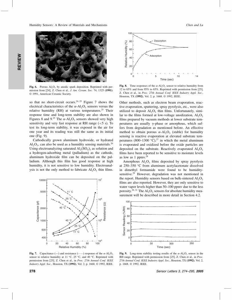
so that no short-circuit occurs.2425 Figure 7 shows theelectrical characteristics of the -Al2O3 sensors versus therelative humidity (RH) at various temperatures.25 Theirresponse time and long-term stability are also shown inFigures 8 and 9.25 The -Al2O3 sensors showed very highsensitivity and very fast response at RH range (<5 s). Totest its long-term stability, it was exposed in the air forone year and its reading was still the same as its initialone (Fig. 9).
Cathodically grown aluminum hydroxide, or hydratedAl2O3, can also be used as a humidity sensing materials.26
Using electroanalyzing saturated Al2(SO4)3 as solution anda hydrogen-adsorbing metal (palladium) as the cathode,aluminum hydroxide film can be deposited on the pal-ladium. Although this film has good response at highhumidity, it is not sensitive to low humidity. Electroanal-ysis is not the only method to fabricate Al2O3 thin films.
11 ˚C
25 ˚C
40 ˚C
11 ˚C
25 ˚C
40 ˚C
Relative Humidity (%)
Res
ista
nce
(Ω)
Cap
acita
nce
(pf)
0
400
600
2000
5000
10000
1000
107
106
105
104
20 100806040
Fig. 7. Capacitance (—) and resistance (- - - -) response of the -Al2O3
sensor to relative humidity at 11 C, 25 C, and 40 C. Reprinted withpermission from [25], Z. Chen et al., in Proc. 27th Annual Conf. IEEEIndustry Appl. Soc., Houston, TX (1992), Vol. 2, p. 1668. © 1992, IEEE.
Rel
ativ
e H
umid
ity (
%)
Time (sec)
Adsorption
Desorption
0 100
20
40
60
80
100
5 14
Fig. 8. Time responses of the -Al2O3 sensor to relative humidity from12 to 65% and from 95% to 65%. Reprinted with permission from [25],Z. Chen et al., in Proc. 27th Annual Conf. IEEE Industry Appl. Soc.,Houston, TX (1992), Vol. 2, p. 1668. © 1992, IEEE.
Other methods, such as electron beam evaporation, reac-tive evaporation, sputtering, spray pyrolysis, etc., were alsoutilized to deposit Al2O3 thin films. Unfortunately, simi-lar to the films formed at low-voltage anodization, Al2O3
films prepared by vacuum methods at lower substrate tem-peratures are usually -phase or amorphous, which suf-fers from degradation as mentioned before. An effectivemethod to obtain porous -Al2O3 (stable) for humiditysensing is reactive evaporation at elevated substrate tem-peratures (800–1300 C),27 in which the metal aluminumis evaporated and oxidized before the oxide particles aredeposited on the substrate. Reactively evaporated Al2O3
films have been reported to be sensitive to moisture levelsas low as 1 ppmv.28
Amorphous Al2O3 films deposited by spray pyrolysisat 250–350 C from aluminum acetylacetonate dissolvedin dimethyl formamide were found to be humidity-sensitive.29 However, degradation was not mentioned inthe report. Humidity sensors based on bulk-sintered Al2O3
films are also reported. However, they are only sensitive towater vapor levels higher than 50–100 ppmv due to the lessporosity.3031 The Al2O3 sensors for absolute humidity mea-surement will be described in more detail in Section 4.2.
Time (sec)0 300
Sen
sor
Rea
ding
(%
RH
)
0
20
40
60
80
100
50 350
Fig. 9. Long-term stability testing results of the -Al2O3 sensor in theRH range. Reprinted with permission from [25], Z. Chen et al., in Proc.27th Annual Conf. IEEE Industry Appl. Soc., Houston, TX (1992), Vol. 2,p. 1668. © 1992, IEEE.
278 Sensor Letters 3, 274–295, 2005

REVIEW
Chen and Lu Humidity Sensors: A Review of Materials and Mechanisms
3.1.2. TiO2
TiO2 has three phases: anatase, rutile, and brookite. Thethird one is seldom used in humidity sensing. When heatedstrongly (∼1000 C), anatase automatically transforms tothe rutile structure.32 Rutile is the most common phase ofTiO2, while anatase is very rare in nature. At high tem-perature (∼600 C), anatase is an n-type semiconductorbut rutile is a p-type one.33 Their sensing responses toreducing gases like H2 usually behave on the oppositedirections. However, because humidity sensing is usuallyrealized by the adsorbed proton-conducting water layerson the porous structure at room temperature,73435 bothphases should behave approximately the same in resistanceor capacitance changes. In this section, we will considerTiO2 as a surface protonic/ionic conducting material, nota semiconducting sensing material.For humidity sensing applications, anatase TiO2 are usu-
ally made by sol–gel method. The sintering must be atlow temperatures (e.g., <500 C) for short time. Other-wise, TiO2 may be turned into rutile. Due to its higherwater adsorption capacity,36 anatase is a preferred humid-ity sensing material. Most commercial TiO2 powders haverutile phase, which can be fabricated by sputtering, ther-mal evaporation,37 pulse laser deposition,38 and lasermolecular-beam epitaxy.39
Because of its protonic conducting sensing mechanism,doping with alkali ions may improve the conductivity ofTiO2.
40–42 Adding SnO2 increases its porosity and thusenhances the sensitivity at high RH range (>70% RH).43
In addition, bilayered TiO2/SnO2,44 TiO2/Al-doped ZnO,45
and ZrO2/SnO246 were reported to have less hysteresis than
pure TiO2, Al-doped ZnO, and ZrO2. In these bilayeredstructures, one material is responsible for fast-adsorption,the other one is responsible for fast-desorption, and porousTiO2 facilitates the adsorption process of water vapors inthe pores. Furthermore, doping of electrolytes or ions, e.g.,P2O5
47 or potassium48 may considerably enhance the sen-sitivity. However, most TiO2-based sensors using the abovefabrication methods are not sensitive at low humidity lev-els and have limited detection ranges from 10% to 30%RH.364243 A newly developed TiO2 nanowire sensor isonly capable to detect relative humidity levels down to11%.49 For K+-doped TiO2 film sintered at a temperaturebelow 500 C, it is capable to sense humidity levels lowerthan 10%.48 In addition to resistive/capacitive sensors, sen-sors based on magneto-elastic method was found to besensitive to a humidity level of 2% RH,50 in which thechange of mass of TiO2 (pore size around 80 nm) due towater-adsorption is measured.
3.1.3. SiO2
Although SiO2 grown by wet or dry oxidation has beenused as an insulator in electronics for a long time, it isdefinitely not suitable for humidity sensing because it is
a dense material. Humidity sensors based on porous sili-con oxide were fabricated using bulk-sintering processes,especially traditional sol–gel method, in which SiO2 is pre-cipitated by hydrolysis of certain alkoxide of silane.51–53
Nonetheless, the most prominent merit of SiO2 as a humid-ity sensing material is its compatibility with the currentmicroelectronics industry. Similar to other porous ceramicmaterials, the humidity sensitivity of SiO2 can be enhancedby adding electrolyte dopants, e.g., LiCl.54 Although it wasreported that sol–gel fabricated SiO2 sensor could detecthumidity as low as 4% RH,51 most reported works showedthat only humidity over 20% RH can be detected.52–54
During the last few years, humidity sensors based onsilicon monoxide (SiO), a powder that is used as a coat-ing material, have been prepared by a novel film fabrica-tion method, glancing angle deposition (GLAD). In thismethod, the substrate is highly oblique to the incidentvapor flux and isolated columns of the material depositedgrow toward the vapor source.55 It is possible to controlthe film microstructure on a 10 nm scale.5657 Although theSiO films deposited by GLAD are not sensitive to humid-ity levels lower than 15% RH, the response and recoverytimes are as short as in milliseconds. These may be thefastest humidity sensors ever reported.
3.1.4. Spinel Compounds
The spinel compounds belong to a large group of oxideswith a general composite of AB2O4. A can be a diva-lent metal element, especially in group II, group IIB, andVIIIB. X generally represents a trivalent metal, e.g., iron,chromium, and aluminum. The structure of this group istetrahedron (diamond) always with high density of defects.Although spinel oxides are semiconductors, most of thereported humidity sensors58–60 based on these materialshave ionic sensing properties probably due to their lowoperating temperatures (<100 C). In case that the poresize is very small (100∼ 300 nm), the lower detection limitcan be down to 1% RH.5961 Like other humidity sensingceramics based on proton-conducting mechanism, dopingwith alkali ions facilitates formation of hydrated protons.60
Similar to perovskite oxides, spinel oxides are fabricatedby bulk-sintering of the mixture of two metal oxides.5860
3.1.5. Other Ceramic Sensing Materials
LiCl-doped MnWO4 (a p-type semiconductor) prepared bybulk-sintering was reported to have good linear responseto relative humidity over 30% RH in short response (∼3 s)and recovery (∼15 s) time at room temperature.6263 Scan-ning electron microscopy (SEM) showed different grainand pore sizes of the material in relation to the amount ofadded LiCl.64 Despite their short response/recovery time,thin films are less sensitive than thick films due to theirlack of capillary structures.65 Boron phosphate calcinatedat 350 C was found to be sensitive to RH over 35%.66
Sensor Letters 3, 274–295, 2005 279

REVIEW
Humidity Sensors: A Review of Materials and Mechanisms Chen and Lu
The phosphate cations might dissolve in the adsorbed waterand help the formation of protons. -Fe2O3 (hematite) hasbeen used for humidity sensing dated back to the 60’s ofthe last century.67 After doping with silicon and sinteringat 850–950 C, the average pore size of -Fe2O3 is ∼25 Å.The -Fe2O3 sensors can response to RH below 5%.67
3.2. Semiconducting Sensing Materials
Some ceramic oxides or composite oxides such as SnO2,ZnO, and In2O3, etc. are wide-bandgap semiconductors.H2O is adsorbed on the oxide surface in molecular andhydroxyl forms. Water molecules are observed to increasethe conductivity of n-type ceramics and to decrease theconductivity of p-type ceramics.6869 This effect has beenattributed to the donation of electrons from the chemi-cally adsorbed water molecules to the ceramic surface.68
Another mechanism was proposed.7071 It was suggestedthat water molecules replace the previously adsorbed andionized oxygen (O−, O2−, etc.) and therefore releasethe electrons from the ionized oxygen.7071 Probably the“donor effect” could be resulted from both.Because the conductivity is caused by the surface
concentration of electrons, this sensing style is usuallycalled “electronic type.” However, the water layer formedby the physical adsorption may be somewhat proton-conductive. Therefore, at room temperatures the conduc-tivity of ceramic semiconducting materials is actually dueto addition of both electrons and protons (ionic), unless athigh temperatures (>100 C) moisture cannot effectivelycondense on the surface. In Figure 10a, the conductiv-ity increment is produced by surface electron accumula-tion resulting from the preferential alignment of the waterdipoles.68 Hydrogen atoms contact the surface (mostly atthe oxygen sites) and attract electrons outward (Fig. 4).In Figure 10b, a depletion region forms originally due toadsorbed oxygen and the released electrons may neutral-ize the depletion. Since adsorbed water molecules increasethe conductivity of n-type ceramic semiconductors, nearly
Fig. 10. Two possible mechanisms for the “donor effect” (just forn-type): (a) Electrons are attracted by the adsorbed water molecules tothe semiconductor surface and the energy bands are bended; (b) Electronsare released by the competitive adsorption.
all the published works deal with n-type ceramics. It wasreported that the change of conductivity was linear to cer-tain exponential based on the proposed surface reactionmechanism.71 However, most of works lack the derivationfor establishing strict reaction models.72
3.2.1. SnO2
Stannic oxide (SnO2) is an n-type wide-bandgap semicon-ductor. H2O is adsorbed on the oxide surface in molecularand hydroxyl forms and the mechanism was identified tobe electronic.6872 A more complicated SnO2–H2O inter-action model was constructed on considering of waterdesorption in molecular form, dissociative chemisorptionand desorption of OH− groups.73 The water molecule stillbehaves like a donor on the SnO2 surface. Different fromTiO2 and other high-temperature semiconducting ceram-ics, SnO2 shows electronic conductivity at rather low tem-perature (even at room temperatures).68707273 Therefore,SnO2 humidity sensors based on semiconducting proper-ties are expected.An interesting transitional behavior was observed in
step-like humidity changes for sensors based on SnO2 atconsiderably high temperatures (Fig. 11). This is causedby fast competitive adsorption between H2O and adsorbedoxygen species (O2−, O−, etc.) and desorption of theadsorbed oxygen species and releasing of free elec-trons. This phenomenon suggests the electronic conductionmechanism and also confirms the contribution of compet-itive adsorption between H2O and adsorbed oxygen to theconductivity increase. For sensors based on In2O3 or ZnO,similar peak patterns due to step-like humidity changeswere also observed in the temperature range from 230 Cto 540 C. The mechanism should be similar to that ofSnO2 sensors.74
For sensors based on ultra-thin SnO2 films (60–90 nm)prepared by sol–gel process, the response time ranged
Fig. 11. (a) Typical response curves of SnO2 under rectangular pat-tern of humidity change. Sensor operating temperature 460 C, thickness100 mm, calcination temperature 600 C. (b) Changing humidity pattern.Reprinted with permission from [74], T. Kuse et al., Sens. Actuators B67, 36 (2000). © 2000, Elsevier.
280 Sensor Letters 3, 274–295, 2005
REVIEW
Chen and Lu Humidity Sensors: A Review of Materials and Mechanisms
from 8–17 s for different humidity changes and the recov-ery time was only about 1 s, due to their ultra-thin films.75
However, most reported SnO2 sensors are only sensitiveto RH higher than 30%.75–77 In addition to sensing watervapor, SnO2 is widely used for multiple gases, especiallyharmful oxides such as NOX , CO, PbO2. Since these sen-sors are usually operated at temperatures above 200 C,heaters are always attached at the backside.78
3.2.2. Perovskite Compounds
The perovskite compounds belong to a large group ofoxides with a general composition of AXO3. The A canbe any metal element with +2 valence electrons, e.g.,group II, group IV, and rare earth metals. The X representstitanium, niobium, and iron.79 Sometimes A or X could bea combination of two or more elements, e.g., La07Ca03 forA and Zr02Ti08 for X.80 All members of this group havethe same basic structure that is isometric.Perovskite oxides form a group of ceramics that exhibit
a variety of interesting properties and promising appli-cations. N -type perovskite semiconductors exhibit elec-trical conductivity variation as humidity changes andhave high sensitivity to water partial pressure down to0.006 atm.81 However, as mentioned previously, like TiO2,the humidity-sensing property of perovskite oxides isonly effective at elevated temperatures (400–700 C).Therefore, the reported perovskite oxide humidity sens-ing devices, based on electron-conducting mechanism, areoperated at the temperature of hundreds of Celsius.8182
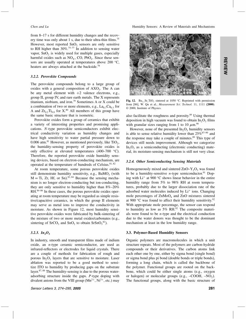
At room temperature, some porous perovskite oxidesstill demonstrate humidity sensitivity, e.g., BaMO3 (withM = Ti, Zr, Hf, or Sn).8384 Because the sensing mecha-nism is no longer electron-conducting but ion-conducting,they are only sensitive to humidity higher than 8%–20%RH.84–86 In these cases, the porous perovskite oxides oper-ating at room temperature may be regarded as simple resis-tive/capacitive ceramics, in which the group II elementsmay serve as metal ions to improve the conductivity inmoisture. As shown in Figure 12, most humidity sensi-tive perovskite oxides were fabricated by bulk-sintering ofthe mixture of two or more metal oxides/carbonates (e.g.,sintering of SrCO3 and SnO2 to obtain SrSnO3
82).
3.2.3. In2O3
In industry, smooth and transparent films made of indiumoxide, an n-type ceramic semiconductor, are used asinfrared-reflectors or electrodes for liquid crystals. Thereare a couple of methods for fabrication of rough andporous In2O3 layers that are sensitive to moisture. Laserablation was reported to be a good method to sensi-tize ITO to humidity by producing gaps on the substratelayer.8788 The humidity-sensing is due to the porous water-adsorbing structure inside the gaps. P -type doping withdivalent anions from the VIII group (Mn2+, Ni2+, etc.) may
Fig. 12. Ba1·xSrxTiO3 sintered at 1050 C. Reprinted with permissionfrom [86], W. Qu et al., Measurement Sci. Technol. 11, 1111 (2000).© 2000, Institute of Physics.
also facilitate the roughness and porosity.89 Using thermaldeposition in high vacuum was found to obtain In2O3 filmswith granular sizes ranging from 1 to 10 m.90
However, none of the presented In2O3 humidity sensorsis able to sense relative humidity lower than 25%87–90 andthe response may take a couple of minutes.89 This type ofdevices still needs improvement. Although we categorizeIn2O3 as a semiconducting (electronic conducting) mate-rial, its moisture-sensing mechanism is still not very clear.
3.2.4. Other Semiconducting Sensing Materials
Homogeneously mixed and sintered ZnO–Y2O3 was foundto be a humidity-sensitive n-type semiconductor.91 Dop-ing with Li+ at 900 C shows linear behavior in the entirehumidity range from 5% to 98% RH at room tempera-tures, probably due to the larger dissociation rate of theadsorbed water molecules induced by Li+ ions. Changingmole percentages of ZnMoO4 and ZnO mixtures sinteredat 900 C was found to affect their humidity sensitivity.92
With appropriate mole percentage, the sensor can respondto humidity as low as 5% RH.92 The composite materi-als were found to be n-type and the electrical conductiondue to the water donors was thought to be the dominantmechanism at least in the low humidity range.
3.3. Polymer-Based Humidity Sensors
Organic polymers are macromolecules in which a unitstructure repeats. Most of the polymers are carbon-hydridecompounds or their derivatives. The carbon atoms linkeach other one by one, either by sigma bond (single bond)or sigma bond plus pi bond (double bonds or triple bonds),forming a long chain, which is called the backbone ofthe polymer. Functional groups are rooted on the back-bone, which could be either single atoms (e.g., oxygenor halogen) or molecular groups (e.g., –COOH, –NO2).The functional groups, along with the basic structure of
Sensor Letters 3, 274–295, 2005 281

REVIEW
Humidity Sensors: A Review of Materials and Mechanisms Chen and Lu
the backbone, determine the chemical and physical proper-ties of the polymers.93 Artificial polymers are synthesizedfrom monomers that are small molecules. Copolymers arepolymers synthesized from two or more different kinds ofmonomers. Polymeric humidity sensors have been widelystudied in research and applied in industry for more than30 years. Most of the sensors are based on porous polymerfilms thinner than millimeters and their sensing principleis quite similar to that of ceramic sensors. The film is filledwith micro-pores for water vapor condensation and someof the measurable physical properties change due to thewater absorption.Traditionally, according to sensing mechanisms, poly-
meric humidity sensors are divided into two fundamentalcategories: resistive-type and capacitive-type.94 The formerresponds to moisture variation by changing its conduc-tivity while the latter responds to water vapor by vary-ing its dielectric constant. Almost all of the humiditysensors based on polymers operate at room temperature,due to polymers’ high sensitivity to heat. However, dur-ing the last ten years, in addition to the traditional quater-nary ammonium and sulfonate compounds,92–96 polymerscontaining phosphonium have been developed for humid-ity sensing.97 More importantly, copolymers and mutuallyreactive copolymers have also been studied for humiditysensing.98 Humidity sensors based on conjugated polymersthat are conductive polymers but not polymeric electrolytesattract considerable attention in research laboratories andindustries.99100 These new materials along with ammo-nium and sulfonate polymers will be discussed in detail inthis section. In addition, polymeric humidity sensors otherthan electrical impedance measurements (conductance andcapacitance), such as piezoresistive101 and surface waveacoustic (SAW)102 devices, will also be described in thissection. Optical sensors, in which polymers are used tocoat fibers,103 will not be discussed in this section.
3.3.1. Polyelectrolyte-Based Resistive Sensors
Almost all of the polymeric resistive humidity sensorsare based on two types of materials: polyelectrolytes andconjugated polymers. For both types of materials, theconductivity of most polymers decreases with increasinghumidity level. However, the conductivity of the former isalways lower, due to its ionic functional groups. Generallyspeaking, polyelectrolytes are hydrophilic or even water-soluble, while conjugated polymers (conducting or semi-conducting polymers) are rather hydrophobic and unable toabsorb much water. To fabricate humidity sensors based onpolyelectrolytes, it is reasonable to use some methods toavoid deformation caused by dissolving94 and to enhancethe sensitivity by lowering the intrinsic conductivity.104
For sensors based on conducting/semiconducting polymers,dispersing some ions inside the materials leads to reductionin resistivity at low RH99 and thus generates greater abso-lute signals. The configuration of most resistive sensors, as
well as of capacitive sensors that will be discussed later, iseither a sandwiched structure with electrodes on both sidesor interdigited electrodes with deposited polymer films inbetween. For the sandwiched structure, the top electrodeis always a vapor-permeable thin metal film, e.g., gold.Polyelectrolytes are polymers with electrolytic groups,
which could be salts, acids, and bases. Based on func-tional groups, humidity-sensitive polyelectrolytes can befundamentally divided into three major categories: qua-ternary ammonium salts,105–113 sulfonate salts,114115 andphosphonium salts.9798116–118 To absorb moisture, thepolyelectrolytes are usually prepared as porous thin films.Ammonium and sulfonate salts are traditional polyelec-trolytes used in moisture sensing. During the last fewyears, phosphonium salts were developed. Since phos-phorous is just below nitrogen in the periodic table, thechemical properties of phosphonium are nearly identicalto those of ammonium. Sometimes phosphonium salts arefavored in humidity sensing due to the easy formation oforganic quaternary phosphonium with vinyl monomers.118
As shown in Figure 13, Cl− is a counter ion in dimethyl-diallylammonium chloride, while Na+ is a counter ion inpoly(sodium p-styrene sulfonate). Apparently, the mobilityof the counter ions in polyelectrolytes is very high.In addition to the ionic compounds introduced above,
it is reported that KOH (potassium hydroxide)-H2O-dopedPVA (poly(vinyl alcohol)) is sensitive to RH over 50%.119
The backbones of the polyelectrolytes are commonlyhydrophobic, while the electrolytic groups are quite sol-uble in water. As water absorbed on these porous films,the conduction mechanism is similar to that of the zeo-lites doped with electrolyte ions, which is a water-phaseelectrolyte material (see Section 3.1). Ions dissolved in thewater layer formed by absorption become carriers of elec-tric conduction. The counter ions comprise the majority ofthe carriers due to their high mobility. The conductivityof the films increases as humidity increases. From theirstructures, it is easy to find three major drawbacks of theporous films made of polyelectrolytes. First, the materi-als are soluble in water and the counter ions are ready toexchange with H+ or OH−, especially at high humiditylevels or in cases when dews form. Second, deformationdue to change of humidity or temperature lowers their per-formance and shortens their lifetime. Additionally, due totheir high solubility the conductivity reaches a very highvalue even if humidity is little. Therefore their sensitivityto high RH is quite weak.
Fig. 13. Two typical polyelectrolytes.
282 Sensor Letters 3, 274–295, 2005

REVIEW
Chen and Lu Humidity Sensors: A Review of Materials and Mechanisms
Fig. 14. Simultaneous cross-linking and quaternization of poly chloro-methyl styrene with diaminoalkane. Reprinted with permission from[107], Y. Sakai et al., Sens. Actuators B 66, 135 (2000). © 2000, Elsevier.
Back to 1839, Charles Goodyear vulcanized naturalrubber using sulfur by cross-linking the isolated poly-meric rubber chains into an intensive network.120 Forhumidity sensing polyelectrolytic films, the same method(cross-linking) is used to enhance the mechanical prop-erties of the sensors, as well as preventing dissolvingof ions and strengthening the adherence to the subst-rate.9798105–108112–117 Figure 14 shows a cross-linkingreaction.107 The diaminoalkane (the compound at thecenter) forms a “bridge” that connects two polymerchains together so that a dense, insoluble, and inten-sive polymer network is resulted. Note that the cross-linking reagent (diaminoalkane) becomes the electrolytic(humidity-sensitive) group of the network and the cross-linking and ammonium-quaternization are accomplished atthe same time.In many cases, simple cross-linking cannot assure satis-
factory insolubility, lifetime, and intensity. Based on cross-linking interpenetrating polymer network (IPN) has beendeveloped.106115 IPN consists of a cross-linked polyelec-trolyte and a cross-linked hydrophobic polymer. The twocross-linked polymers interpenetrate each other. Figure 15shows two typical IPNs, the ethylene glycol dimethacry-late (EGDMA) that is a cross-linked hydrophobic polymerand poly(AMPS-co-PGM) that is a cross-linked poly-electrolyte. AMPS means 2-acrylamido-2-methylpropanesulfonic acid and PGM means polypropylene glycolmonomethacrylate. poly(AMPS-co-PGM) is a copoly-mer synthesized from the mixture of AMPS and PGMmonomers. Melamine resin cross-links the poly(AMPS-co-PGM) chains.In addition to using chemical reagents, the cross-linking
can also be accomplished by Co60 radiation as well as bythe radiation of UV light.105121122 Graft-polymerizing, inwhich electrolytic groups are grafted on a pre-preparedpolymer backbone that comprises a porous film, is also agood method to make the sensing film resistive to water.94
The cross-linking and IPN are primarily dealing withthe solubility and deformation, but have little to do with
Fig. 15. Interpenetrating polymer networks (IPN). Reprinted with per-mission from [115], Y. Sakai et al., Electrochim. Acta 46, 1509 (2001).© 2001, Elsevier.
enhancement of sensitivity. The sensitivity becomes quitelow at high humidity due to its low resistivity at low RH.According to researchers,9798108–118 this problem can besolved by adding some insulating content into the highlyconductive polyelectrolytes. The inserted insulting parts isable to absorb enough water, dilute the ion concentration,and limit the mobility of ions.104 Therefore, hygroscopicinsulating polymers, like PVA and polyesters, are alwaysfavored. This method is proved to be effective for loweringthe conductivity of polyelectrolytes at low RH and enhanc-ing sensitivity at high RH. Figure 16 illustrates a typical
Fig. 16. Reaction to form a copolymer. Reprinted with permission from[117], M. S. Gong et al., J. Mater. Sci. 37, 4615 (2002). © 2002, Elsevier.
Sensor Letters 3, 274–295, 2005 283

REVIEW
Humidity Sensors: A Review of Materials and Mechanisms Chen and Lu
synthesis reaction for preparing a copolymer, i.e., mixingtwo monomers in appropriate solvent under proper con-ditions. The reactant on the left is the electrolyte, (vinyl-benyl) tributylphosphonium chloride, and on the right isthe hygroscopic insulating compound, an ester.Humidity-sensitive copolymer films can also be cross-
linked to enhance the performance,97108116118 or evenform IPNs with a cross-linked hydrophobic polymer.115
Recently, cross-linked copolymers resulted from mutuallyreactive polymers have been developed.98110–113 Differentfrom traditional cross-linking, in which chains of the samepolymer are jointed together, two different polymers (mutu-ally reactive polymers) are bridged together in this process.There is no bridging reagent or radiation needed in thecross-linking process and the connection between the tworeagents is accomplished by direct reactions. At least one ofthe two mutually reactive polymers (reagents) is a copoly-mer as discussed in the above few paragraphs. A mutuallyreactive cross-linking is illustrated in Figure 17110 and thequarternization is finished simultaneously.The product of the reaction in Figure 17 is some-
what similar to the IPN (see Fig. 15). This indicates thatthe cross-linked structure from mutually reactive polymersmay have mechanical properties as good as IPNs, of whichthe process is much more complicated. Based on polyelec-trolytes, many humidity sensors are able to response to RHfrom 20% to 90% with good linearity98108110–112116–118
and some of them are even sensitive to RH around10%.106107
3.3.2. Conducting/Semiconducting Polymers
In polymers and single molecules, sometimes doublebonds and single bond may occur alternately along themain chain. This structure is called conjugation, which isa key thing for semiconductive and conductive polymers.A conjugation structure existing along the entire mainchain is named universal conjugation (Fig. 18). Conduc-tive polymers were first reported in 1977.123 As verifiedby theories and experiments,124 the greater the degree ofconjugation, the narrower is the band gap, because morebonding electrons are delocalized. The band gap of highlyconjugated polymers is small (∼2 eV) and that of saturatedpolymers is high (∼10 eV). The reason for the decreasingband gap is that the conjugating structure delocalizes thebonding electrons and the system energy is reduced. If theconjugation is universal, its degree can be represented bythe degree of polymerization. For highly conjugated poly-mers with high polymerization degree, the intermolecularresistance becomes negligible in the bulk. This is becausethe intermolecular energy gap for charge carrier to over-come is quite small, which is usually less than 0.1 eV forhigh degree of polymerization due to the Van der Waalsforce that increases with mass.Like intrinsic silicon, despite containing universally
conjugated chains the intrinsic conducting polymers are
Fig. 17. Cross-linking by mutually reactive copolymers. Reprinted withpermission from [110], S. H. Park et al., Sens. Actuators B 86, 68 (2002).© 2002, Elsevier.
not very conductive because of shortage of free chargecarriers. Also, radiation with photon energy higher thanthe band gap could enhance the conductivity by excit-ing electrons from the valence band to the conductionband. The conducting mechanism of intrinsic polymerscould be interpreted by the principles of electron–hole pairtraveling under electric field.125 However, the traveling isone-dimensional rather than three-dimensional due to thestructure of conjugated polymers. Since most conductivepolymers lack completely equivalent carbon sites along themain chain, some charges are localized and the band gapis therefore enlarged. The sites that trap the carriers arenamed polarons (a polaron with two charges is called a“bipolaron”) and the process in which carriers overcomethe polaron barrier(s) is called “hopping.”At room temperature, the conductivity of intrinsic poly-
acetylene is very low, only 10−7 to 10−8 S cm−1 (thatof intrinsic silicon is about 4× 10⁻⁶ S cm−1). Similar toinorganic semiconductors, the conductivity of polymerscan be considerably enhanced by doping. The doping ofpolymers is actually to oxidize (p-type doping) or reduce(n-type doping) the backbone by chemical agents.126127
The oxidation/reduction also generates by-products, likepositive or negative ions. These ions become part of the
Fig. 18. Poly(p-phenylene vinylene), a typical conducting polymer withuniversal conjugation.
284 Sensor Letters 3, 274–295, 2005

REVIEW
Chen and Lu Humidity Sensors: A Review of Materials and Mechanisms
polymer to keep the net charge to be zero. They are usu-ally called “counter ions.” It is expected that a p-typepolymer semiconductor may contain negative counter ionsand an n-type one may contain positive counter ions. Incase that sufficient amount of water is absorbed on thedoped polymers, one may expect that polymers may showsome ionic conduction with the counter ions as the car-riers. It is known that the conductivity of extrinsic sili-con is very high (>1000 S cm−1). However, for generalpolymers (polyacetylene or polyphenylene) with moder-ate doping (either p-type or n-type), the conductivity mayvary from 0.1 to 1 S cm−1. In recent years, several devicesbased on conducting/semiconducting polymers werebuilt, including LEDs,128 solar cells,129 and field-effecttransistors.130
Water is well known for its protonation and the releasedproton interacts with universally conjugated C C doublebonds. This effect was discovered and used for humid-ity sensing. Generally, dopants always play an impor-tant role in the conductivity variation caused by absorbedwater.131132 As conducting polymers, polyaniline (PANI)and its derivatives have been found to be humidity-sensitive for a long time.133–135 Due to polymerization bysome strong oxidant (e.g., (NH4)2S2O8), the PANI struc-ture contains two basic forms: non-oxidized (reduced) andoxidized structures (Fig. 19). Apparently, the PANI syn-thesized in this way may be regarded as p-type doping.Due to the un-bonded electron pair on the nitrogen atom,both forms can be protonated: NH → NH+
2 andN → NH+ . According to a buildup model,133136
the electron transferring (hopping) from the protonatedreduced form ( NH+
2 ) to the protonated oxidized form( NH+ ) is the dominant conduction process of PANIwhen water content reaches 0.1% (mole ratio). Since inthis process a proton is transferred to water by the reaction,NH+
2 +H2O → NH+ +H3O+, absorbed water
plays an important role in the conductivity. The humidity-sensing property of PANI to water vapor can be regardedas electron hopping assisted by proton exchange. Its con-duction is both electronic and ionic. The ionic conductionis favorable as long as mobile counter ions (for exam-ple, Cl−) exist in the polymer.135 Although it is verifiedthat PANI and its derivative are sensitive to humidity,the response is very low due to weak hygroscopicity, atmost one order of magnitude change in conductivity.133136
Using a similar methodology in polyelectrolytes, someresearchers combine (o-phenylenediamine) (PoPD, a close
Fig. 19. Two redox forms of polyaniline (in the reduced form, the un-bonded electron pair on the nitrogen atom contributes to the conjugation).
structure to PANI) with hygroscopic polymers like PVAto enhance the response.99137138 The hygroscopic PVAabsorbs water molecules from poly in the drying stage andprovides water molecules to PoPD as humidity increases.As reported, the composite PoPD/PVA is able to detectRH below 10%.99137 Some hysteresis is observed in thistype of sensor after long-term operation or short expo-sure to high humidity. Researchers attribute it to a layerof sulfuric acid that is formed from the dopant (fumingsulfuric acid).137 A major drawback of PANI is its poorprocessibility. It is reported that converting PANA (Poly(anthranilic acid)) into PANI by heat treatment turns tobe a convenient method for fabricating PANI with goodhumidity-sensing property.139 The doped composite film ofpoly(o-anisidine)/PVA, which is also a derivative of PANI,was reported to be humidity-sensitive.140
Poly(p-diethynylbenzene) or PDEB is a conductingpolymer due to its long-chain conjugated structure. Asreported in Ref. [100], PDEB synthesized by some organicnickel catalyst is sensitive to RH ranging from 10%to 90% with rather low impedance. More recently, thesame research group reported other conducting polymers,such as Poly(propargyl benzoate) (PPBT),141 p-diethynyl-benzene-co-propargyl alcohol,142 and ethynylbenzene-co-propargyl alcohol (copolymer),143 are also good candidatesfor humidity sensing. All the above sensing polymersare synthesized using the same organic palladium as thepolymerization catalyst and doped with FeCl3, except forPDEB (nickel-catalyzed without Fe-doping) and PPBT(palladium-catalyzed without Fe-doping). The synthesizedPPBT and PA-co-OHP bilayer also response to RH as lowas 10%141 and the other two copolymers only responseto RH over 30%.142143 The merit of ethynylbenzene-co-propargyl alcohol is that for RH over 30% the loga-rithm of the capacitance of the film changes linearly withhumidity and its sensitivity is very high.143 The sens-ing mechanism may be due to the interaction betweenprotons or dopant ions and the universally conjugatedstructure.100141142 For PDEB and PPBT that are not dopedwith FeCl3, the catalyst (nickel or palladium) may playan important role in conductivity by doping ions into thepolymers.
3.3.3. Hydrophobic Polymer-Based Capacitive Sensors
Unlike resistive sensors based on polyelectrolytes, capac-itive polymer films for humidity-sensing are made fromhydrophobic organic materials that are somewhat hygro-scopic in order to absorb moisture.94 In other words, thepolymers for capacitive sensors should be both non-ionicand highly polar macromolecules. In the market, capac-itive sensors are usually more expensive than resistivesensors due to their high fabrication cost.144 However,with excellent linear response,144–146 capacitive sensorsare far more attractive than resistive sensors. This linearresponse is due to a very simple principle described
Sensor Letters 3, 274–295, 2005 285

REVIEW
Humidity Sensors: A Review of Materials and Mechanisms Chen and Lu
Fig. 20. Kapton, a typical polyimide.
as follows. For insulating polymers, the absorbed water,the weight of which is proportional to relative humid-ity, occupies the free space between the polymeric mole-cules. Therefore the change of the dielectric constant ofthe hygroscopic polymer is linearly proportional to theamount of water absorbed. To be non-ionic but verypolar, polyimides,144–149 and esters are apparently goodcandidates, such as cellulose acetate butyrate (CAB),150–152
poly(methyl methacrylate) (PMMA),153154 poly(vinylcrotonate),121 and poly(ethyleneterephthalate) (PETT).155
Figure 20 illustrates a typical polymer for capacitivehumidity-sensing. Models for moisture sensing in bothmaterials have been established.144150 Hysteresis is usu-ally a serious problem in capacitive sensors. Hysteresiscomes from clusters of absorbed water inside the bulkpolymer.94152 Formation of clusters indicates that hygro-scopicity of some polymers is too high and relatively largevoids exist in the polymeric structures. The water clustersmay also deform the polymers and shorten the lifetimes ofthe sensors.In the previous section (Section 3.2.1), we discussed the
application of cross-linking to solve the deformation andaging caused by water absorbed in polyelectrolytes. Forcapacitive sensors, the cross-linking method,121122153154
in which hygroscopicity is lowered and the resistanceis enhanced due to temperature change,121 is also usedto against the hysteresis. Some hygroscopic cross-linkingagents can also enhance the sensitivity of the film.154
Polyimides, which are used as insulators in integratedcircuits,147148 are the most commonly used group ofmaterials for capacitive humidity sensors94144–148 and theresponse is always linear with the detection limit gen-erally below 20% RH. In addition, polyimides can alsobe used as substrates for humidity sensors.149 The poly-imide (Kapton) can be doped with carbon to become con-ductive. Between the polyimide substrate and the sensingfilm (made of other polymers), the adherence is strongand the mismatch in thermal coefficients is small. Itis also reported that carbon filled polysulfone can beused as good electrodes for humidity sensors based onpolyimides.145
Other polymers suitable for capacitive humidity sensorsinclude polyethersulphone (PES),144 polysulfone (PSF),156
divinyl siloxane benzocyclobutene (BCB),157 hexamethyl-disilazane (HMDSN),158 etc. The capacitive humidity sen-sors have linear response as low as 15% RH121144148155
and some have very low hysteresis (<2%).144146156
4. ABSOLUTE HUMIDITY SENSORS(HYGROMETERS)
In early years, meteorologists were interested in an instru-ment capable of measuring the water content of the upperair latitudes where the water concentration was less than10 ppmv at air temperature of −56 C.159 In 1948, adew/frost hygrometer based on moisture condensation ona mirror was developed to measure the absolute humid-ity in extremely dry air of stratosphere with the lowestdetectable humidity level of −90 C frost point.159 In 1967,a fully automated dew/frost point hygrometer based ona mirror with much better performance was developedwith much faster response.160 In 1978, a solid-state mois-ture sensor based on porous anodic aluminum oxide wasdeveloped with fast response and wide measurement range(−110 C to +50 C).161 In following two sections, wewill review the mirror-based hygrometers and solid-basedmoisture sensors.
4.1. Mirror-Based Dew/Frost Point Sensors(Hygrometers)
The basic structure of a dew/frost hygrometer is shownin Figure 21.160 Light from the Farmer electric lamp isprojected onto the sensing element and is received by thephoto resistor. If water condenses on the gold mirror ofthe sensing element, the photo resistor picks up the opticalsignal and the corresponding temperature is recorded. Dur-ing 1990s, people had renewed interests in improvementof the mirror-based dew/frost hygrometers. The improve-ment was focused on the sensing element, i.e., how toaccurately detect temperature at which water begins tocondense on the mirror surface? In order to stabilize themirror temperature, additional heat was injected into themirror.162163 The experimental results showed that temper-ature was many times faster and over-condensation wasminimized. The temperature fluctuations around the dewpoint usually were not over 0.03 K. During the hygrome-ter operation, the heat pump cools the mirror and simul-taneously gives out a huge amount of heat into the heathousing. This temperature change influences the sensitivityof the optical dew detector, which decreases the hygrome-ter’s accuracy. In order to solve this problem, optical fiberswere used to separate the optical dew detector from themirror area as shown in Figure 22.164 The accuracy of thehygrometer was significantly improved at elevated tem-peratures. At 50 C, the error of the fiber optical dewdetector is ∼−0.10 to −0.11 C while the regular opti-cal dew detector is ∼−0.63 to −0.65 C.164 It was shownthat the dew could be detected from the laser light scat-tered from the rough surface of a metal plate insteadof the mirror surface.165 The dew point was determinedwith an accuracy of ±0.5 C, corresponding to ±2% inrelative humidity at a temperature of 27 C. The laserlight was supplied through an optical fiber from a laser
286 Sensor Letters 3, 274–295, 2005

REVIEW
Chen and Lu Humidity Sensors: A Review of Materials and Mechanisms
Fig. 21. Frost/dew point hygrometer assembly. Reprinted with permission from [160], S. H. Jury et al., Anal. Chem. 39, 912 (1967). © 1967, AmericanChemical Society.
Sensor Letters 3, 274–295, 2005 287
REVIEW
Humidity Sensors: A Review of Materials and Mechanisms Chen and Lu
Fig. 22. Schematic of the hygrometer measurement head with fiberoptical dew point detector. Reprinted with permission from [164], R. S.Jachowicz et al., Sens. Actuators A 42, 503 (1994). © 1994, Elsevier.
diode and the scattered laser light was transmitted to aphototransistor also through an optical fiber. The responsetime of this laser dew-point hygrometer is ∼0.2–3 minor 12–180 s.166 Although the absolute humidity is tem-perature independent, the technique for dew point mea-surement is still temperature dependent. One way to solvethis problem is to use optical fiber as described above.Another way is to use a single micro-air-bridge heater toeliminate the influence of the ambient temperature in abso-lute humidity sensing by a thermal sensor.167 In order todevelop a new way to use a Peltier device (thermoelec-tric cooler) for fast humidity sensing, the optical signalof a photodetector was studied when water condensationappears on the cold side of the Peltier device.168 The ther-moelectric device was used at a pulsed rate. During cool-ing, the applied current is stopped as soon as a variationof the optical response, due to the appearance of waterdroplets, is observed. A reverse pulse is then applied toreturn quickly to the ambient temperature. The delay timeof the optical detection is in the range of 0.25–12.2 sfor humidity in the range of 15–70%.168 The schematicof the optical dew detector is shown in Figure 23.169 Itis composed of a single-stage thermoelectric cooler stuck
Fig. 23. Schematic of the dew point sensor. Reprinted with permissionfrom [169], B. Sorli et al., Sens. Actuators A 100, 24 (2002). © 2002,Elsevier.
Fig. 24. Optocoupler polarization. Reprinted with permission from[169], B. Sorli et al., Sens. Actuators A 100, 24 (2002). © 2002, Elsevier.
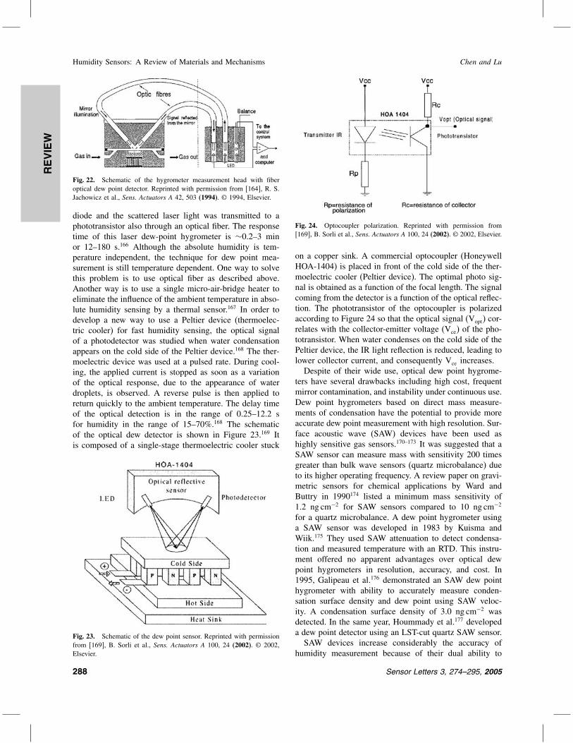
on a copper sink. A commercial optocoupler (HoneywellHOA-1404) is placed in front of the cold side of the ther-moelectric cooler (Peltier device). The optimal photo sig-nal is obtained as a function of the focal length. The signalcoming from the detector is a function of the optical reflec-tion. The phototransistor of the optocoupler is polarizedaccording to Figure 24 so that the optical signal (Vopt) cor-relates with the collector-emitter voltage (Vce) of the pho-totransistor. When water condenses on the cold side of thePeltier device, the IR light reflection is reduced, leading tolower collector current, and consequently Vce increases.Despite of their wide use, optical dew point hygrome-
ters have several drawbacks including high cost, frequentmirror contamination, and instability under continuous use.Dew point hygrometers based on direct mass measure-ments of condensation have the potential to provide moreaccurate dew point measurement with high resolution. Sur-face acoustic wave (SAW) devices have been used ashighly sensitive gas sensors.170–173 It was suggested that aSAW sensor can measure mass with sensitivity 200 timesgreater than bulk wave sensors (quartz microbalance) dueto its higher operating frequency. A review paper on gravi-metric sensors for chemical applications by Ward andButtry in 1990174 listed a minimum mass sensitivity of1.2 ng cm−2 for SAW sensors compared to 10 ng cm−2
for a quartz microbalance. A dew point hygrometer usinga SAW sensor was developed in 1983 by Kuisma andWiik.175 They used SAW attenuation to detect condensa-tion and measured temperature with an RTD. This instru-ment offered no apparent advantages over optical dewpoint hygrometers in resolution, accuracy, and cost. In1995, Galipeau et al.176 demonstrated an SAW dew pointhygrometer with ability to accurately measure conden-sation surface density and dew point using SAW veloc-ity. A condensation surface density of 3.0 ng cm−2 wasdetected. In the same year, Hoummady et al.177 developeda dew point detector using an LST-cut quartz SAW sensor.SAW devices increase considerably the accuracy of
humidity measurement because of their dual ability to
288 Sensor Letters 3, 274–295, 2005

REVIEW
Chen and Lu Humidity Sensors: A Review of Materials and Mechanisms
Fig. 25. The experimental surface acoustic wave delay line configura-tion. Reprinted with permission from [177], M. Hoummady et al., Sens.Actuators B 27, 315 (1995). © 1995, Elsevier.
detect dew condensation and to measure the temperaturewith a great accuracy. The experimental SAW device iscooled using a Peltier device. When water vapor conden-sation appears on the Rayleigh wave propagation path, itinduces a substantial attenuation of the wave amplitudeand a shift in the associate oscillator’s frequency (massloading). Figure 25 shows a schematic of a SAW devicebased on a quartz substrate.177 The quartz cut was an LST-cut because of its high thermal sensitivity and good linear-ity. The interdigital transducers are photolithographicallypatterned on an aluminum film of 1500 Å. The wavelengthwas 34.4 m and the operating frequency about 98 MHz.The SAW device was placed in an oscillator loop. Thequartz plate was cooled by means of a Peltier device gluedon the bottom face (Fig. 26) in order to condense thewater vapor on the SAW propagation path. The hot side ofthe Peltier element was water cooled. It has been shownthat the amplitude depends minimally on the temperaturewhile decreases rapidly when sufficient water vapor con-denses on the quartz plate. This effect depends on thedew thickness/acoustic wavelength ratio. The frequencymeasurement was used for detecting dew deposition.177 Incomparison with the optical dew point detectors, the accu-racy of the SAW devices was improved by about a fac-tor of 500.177 Coating of the SAW device with Teflon AFreduces contamination build-up and allows for accurate
Fig. 26. Principle of an acoustic wave dew point sensor. Reprinted withpermission from [177], M. Hoummady et al., Sens. Actuators B 27, 315(1995). © 1995, Elsevier.
Fig. 27. The silicon dew point sensor. Reprinted with permission from[179], R. Jachowicz and J. Weremczuk, Sens. Actuators A 85, 75 (2000).© 2000, Elsevier.
dew point measurement with improved response time atvery low water vapor concentration.178
Water molecules exist in the form of either ice crys-tals or liquid water (called sub-cooled water) at negativetemperatures. Generally, in nature, sub-cooled water is notstable and spontaneously converts into ice. However, onthe mirror of a dew point hygrometer, this phenomenonmay persist for hours. The partial pressure of saturatedwater vapor over a mirror is different for a mirror cov-ered by ice than for a mirror covered by sub-cooled watereven at the same temperature.179 Therefore, in the temper-ature range of potential sub-cooled water presence (from0 C to −40 C), the hygrometer can measure either frostpoint or dew point, where there is a temperature differenceT . The sub-cooled water error T is about −1 C pereach 10 C below zero. In order to solve the sub-cooledwater issue, a silicon dew point detector was designedas shown in Figure 27.179180 The dew point temperaturewas measured with an embedded RTD thermometer. Thecapacitive detector was used for water and ice recogni-tion. Two heaters were also designed with one located inthe membrane (inner heater) and the other in the solidstructure (outer heater) for fast temperature control sur-rounded both the detector and the thermometer. A modelwas developed to describe the water vapor contained in themeasured gas, water mass transport, heat transport acrossthe measurement head, silicon dew detector, and regulatorcharacteristics.181
4.2. Aluminum Oxide Moisture Sensors
In the above section, the moisture level is measured bydetecting the dew/frost point when the mirror is cooled toa point where water vapor condenses on it. The dew/frostpoint hygrometer is a complex system, which usuallyhas very high cost. It will be very useful if a solidstate sensor can be developed for absolute humidity mea-surement. Most humidity sensors were found applica-tions in the relative humidity (RH) range. Only aluminum
Sensor Letters 3, 274–295, 2005 289

REVIEW
Humidity Sensors: A Review of Materials and Mechanisms Chen and Lu
Table I. Device failure and water vapor concentration.161
Water vapor concentration (ppmv)
Demonstrated Failure-freeFailure modes failures upper limits
Nichrome disappearance 5,000 to 10,000 500Aluminum disappearance 50,000 to 250,000 1000Gold migration 15,000 to 150,000 1000MOS inversion 5,000 to 20,000 200
oxide thin film sensor can be used for absolute humiditymeasurement.161182–184
Failure analysis of integrated circuit packages identifiedmoisture trapped within the hermetically sealed enclosureas a major reliability problem throughout the semicon-ductor industry. Table I shows the failure-free upper limitof moisture level for device reliability. Water vapor cancause nichrome disappearance, gold migration, and MOSinversion. In the second column, the water vapor concen-tration was listed where these failures were demonstrated.The last column lists the failure-free upper limit. Thefailure-free upper limits are less than 1,000 ppmv. Kovacet al.161182 developed an aluminum oxide sensor for in-situmonitoring of sealed integrated circuit packages. The sen-sor can respond to a moisture level as low as 1 ppmv(−76 C dew/frost point). It is basically a capacitor-likestructure consisting of a bottom aluminum electrode, ananodized porous Al2O3 film, and a thin, water permeablegold top electrode (Fig. 28).161 Based on an equivalentcircuit model,161 the porous Al2O3 film capacitive sen-sor is represented by parallel resistance and capacitance.When water vapor is transported through the permeablegold layer and equilibrates on the pore walls, the numberof water molecules absorbed on the pore determines thetotal complex impedence of the sensor. Using an admit-tance amplifier, a characteristic curve such as that shown inFigure 29 is obtained for the device. The “meter reading” isproportional to the admittance of the sensor. As the mois-ture level decreases, the admittance decreases. At a givenpressure, there is a one to one correspondence between thedew/frost point and the parts per million of water vapor.
Fig. 28. Two types of moisture sensors. Reprinted with permission from[161], M. G. Kovac et al., Solid State Technol. 21, 35 (1978). © 1978,PennWell Corporation.
Fig. 29. Typical calibration of an industrial type Al2O3 moisture sensor.Reprinted with permission from [161], M. G. Kovac et al., Solid StateTechnol. 21, 35 (1978). © 1978, PennWell Corporation.
Based on the porous structure, Nahar et al.183 proposedan improved equivalent electric circuit model. Based ontheir suggestion, a schematic of the circuit is shown inFigure 30. In the diagram, Cs and Rs represent the capac-itance and resistance of the solid walls; Ca and Ra are thecapacitance and resistance of the pore area filled with air;Cb and Rb are the capacitance and resistance of the barrierlayer below the air portion. Ceff denotes the capacitanceof the multiple-dielectric capacitor comprising the sublay-ers: barrier layer, chemisorbed layer, and water condensedin the pore as given by the Maxwell-Wagner effect. Reff
is the parallel resistance of the capacitor. Based on theequivalent circuit, the capacitance and resistance can beobtained as183
C = Cs +CaCb
Ca+Cb
+Ceff (1)
Fig. 30. Schematic of the electrical equivalent circuit model of anAl2O3 moisture sensor.
290 Sensor Letters 3, 274–295, 2005

REVIEW
Chen and Lu Humidity Sensors: A Review of Materials and Mechanisms
and1R
= 1Rs
+ 1Ra+Rb
+ 1Reff
(2)
On considering the actual porous structure of the anodicAl2O3, we have the capacitance and resistance at anyhumidity level183
C = 0s1−A
d+0A
(x′
d+ 1−xab
ab+s
)(3)
R= d
0′′xA
(4)
where 0 is the permittivity of free space, s the dielectricconstant of solid Al2O3 (value 8), a dielectric constant ofair (value 1), A the area of the device, the film porosity,d the Al2O3 film thickness, b the barrier layer thickness, the length of the pore in which water can condense.It is a characteristic length of the sensor. x is the frac-tion of pore area A filled with water. ′ and ′′ are thecomponents of dielectric constant of the barrier layer-chemisorbed layer-water structure. Using this model, the-oretical capacitance and resistance data were calculated.183
The theoretical capacitance data are in good agreementwith the experimental data. There is a slight deviationbetween the theoretical resistance data and the experimen-tal data. Later, Nahar et al.8184185 proposed an improvedtheory based on physical absorption, surface conductionmechanisms, and the dielectric properties of the Al2O3
film. The theoretical results are in excellent agreementwith the experimental data.There is a major drawback for aluminum oxide sensor,
i.e., long-term calibration drift.13186–188 The basic reasonfor long-term drift of sensors using porous anodic alu-minum oxide films is described as follows. The structureof anodic aluminum oxide is amorphous- or -Al2O3 withhexagonal cylindrical pore structure. When the structureexposes to a humid atmosphere, the -phase or amorphousAl2O3 changes to -Al2O3 ·H2O (boehmite).12 This irre-versible phase change causes volume expansion of alu-minum oxide, resulting in the gradual decrease of surfacearea and porosity.132425189 Many researchers tried toimprove the anodic aluminum oxide sensors by aging thealuminum oxide in boiling water or macerating the filmsin some ion solutions.1328188 However, the drift can notbe completely eliminated. Even the commercial aluminumoxide moisture sensors have to be calibrated twice a yearto assure their accuracy.190 This problem seriously hindersthe widespread use of aluminum oxide moisture sensors.As mentioned in Section 3.1.1, -Al2O3 is a very stable
phase. However, it is very difficult to form -Al2O3. It isvery difficult to obtain -Al2O3, because the temperaturefor phase change from to is at least 900 C.191 For-tunately, there is an electrochemical approach to deposit-Al2O3 without high temperature process. Anodic sparkdeposition is a unique process for forming certain ceramiccoatings. Various coatings can be formed on a wide
(a)
(b)
Fig. 31. (a) Schematic structure of the -Al2O3 moisture sensor chip(the detailed structure is shown in the inset); (b) The moisture sensingprobe assembly. Reprinted with permission from [25], Z. Chen et al., inProc. 27th Annual Conf. IEEE Industry Appl. Soc., Houston, TX (1992),Vol. 2, p. 1668. © 1992, IEEE.
variety of substrates by this method.192–196 Brown et al.194
deposited -Al2O3 coatings with thickness of more than100 m by anodic spark deposition in aluminate aqueoussolutions with 150 V applied to the anode. Because ofvery little porosity and large thickness, these coatings arenot good candidates for humidity sensors. Tajima et al.22
deposited porous -Al2O3 films on aluminum plates withthickness less than 10 m in a melt of bisulfates by
Fig. 32. Dependence of capacitance and resistance of the -Al2O3
moisture sensor on absolute humidity in the trace moisture range at 0.5 V,1 KHz, and 25 C. Reprinted with permission from [25], Z. Chen et al., inProc. 27th Annual Conf. IEEE Industry Appl. Soc., Houston, TX (1992),Vol. 2, p. 1668. © 1992, IEEE.
Sensor Letters 3, 274–295, 2005 291

REVIEW
Humidity Sensors: A Review of Materials and Mechanisms Chen and Lu
Fig. 33. Long-term stability testing results of the -Al2O3 moisture sen-sor in the trace moisture range. Reprinted with permission from [25],Z. Chen et al., in Proc. 27th Annual Conf. IEEE Industry Appl. Soc.,Houston, TX (1992), Vol. 2, p. 1668. © 1992, IEEE.
applying 150 V to the anode. Chen et al.2425 success-fully fabricated moisture sensors with capability of detect-ing moisture level as low as 1 ppmv using -Al2O3 filmsformed by anodic spark deposition in the melt of NaHSO4-KHSO4 mixture. X-ray diffraction analysis of the sam-ple shows a range of phases, (113), (030), (012),(110) (116) (104) (024) (124) [a16]. Figure 6shows the SEM images of the anodic-spark-deposited-Al2O3 films.2425 The average pore size is in the rangefrom 1 to 2 m and the porosity is about 30%. The anodic-spark-deposited -Al2O3 films exhibit a continuous openpore structure, i.e., the base of the pores was the aluminumsubstrate, not a barrier film. This causes short circuit of thesensors when a 0.5 V (AC) voltage is applied to sensors.
Fig. 34. Time response of the -Al2O3 moisture sensor in the tracemoisture range. Reprinted with permission from [25], Z. Chen et al., inProc. 27th Annual Conf. IEEE Industry Appl. Soc., Houston, TX (1992),Vol. 2, p. 1668. © 1992, IEEE.
In order to overcome this difficulty, the -Al2O3 film isreanodized in diluted sulfuric acid or borax solution for ashort time to form a thin barrier layer as shown in the insetin Figure 31a. The schematic of the sensor structure andthe moisture sensing probe is shown in Figure 31b. Thefabricated sensors showed high sensitivity for moisturelevel from 1000 to 1 ppmv or −20 to −76 C dew/frostpoint (D/F PT) (Fig. 32). The sensors also demonstratedexcellent long-term stability as shown in Figure 33. Formore than six months, there was no drift for data. Theresponse was also very fast. From the low to the highmoisture level the response time is about 5 s and from thehigh to the low moisture level about 20 s (Fig. 34). There-fore, the long-term calibration-drift occurring in -Al2O3
film sensors was eliminated in the -Al2O3 film sensors.25
5. CONCLUSIONS
Humidity sensors based on various materials for both rel-ative and absolute humidity have been reviewed exten-sively, including ceramic, semiconducting, and polymermaterials. In the majority of publications, there are fewpapers dealing with absolute humidity sensors, which haveextensive applications in industry. We reviewed extensivelyabsolute humidity sensors in this chapter, which is uniquecomparing with other reviews of humidity sensors. Theelectrical properties of humidity sensors such as sensitiv-ity, response time, and stability have been described indetails for various materials and a considerable part of thereview is focused on the sensing mechanisms. In addi-tion, preparation and characterization of sensing materialsare also described. For absolute humidity sensors, mirror-based dew point sensors and solid-state Al2O3 moisturesensors have been described. Each has its own advantages.Mirror-based dew-point sensors are more costly in fabri-cation with better accuracy, while the Al2O3 moisture sen-sors can be fabricated with low cost and used for moisturecontrol more conveniently. As the major problem in Al2O3
moisture sensors, long-term instability, has been solved,-Al2O3 moisture sensors may have promising future inindustry.
Acknowledgments: This work is supported byNational Science Foundation (EPSCoR 0447479),Department of Energy (DE-FG02-00ER4582 and DE-FG26-04NT42171), and Army Research Laboratory(W911NF-04-2-0023).
References and Notes
1. E. Traversa, Sens. Actuators B 23, 135 (1995).2. http://www.iceweb.com.au/Analyzer/humidity_sensors.html (2005).3. F. Ansbacher and A. C. Jason, Nature 24, 177 (1953).4. J. M. Thorp, Trans. Faraday Soc. 55, 442 (1959).5. C. J. T. de Grotthuss, Sur la Décomposition de l’eau et des Corps
Qu’elle Tient en Dissolution à l’aide de l’électricité, Galvanique.Ann. Chim. LVIII, 54 (1806).
292 Sensor Letters 3, 274–295, 2005

REVIEW
Chen and Lu Humidity Sensors: A Review of Materials and Mechanisms
6. T. Moromoto, M. Nagao, and F. Tokuda, J. Phys. Chem. 73, 243(1969).
7. E. McCafferty and A. C. Zettlemoyer, Faraday Discussions 52, 239(1971).
8. V. K. Khanna and R. K. Nahar, J. Phys. D: Appl. Phys. 19, L141(1986).
9. Y. Yeh, T. Tseng, and D. Chang, J. Am. Ceram. Soc. 72, 1472(1989).
10. S. Chakraborty, K. Nemoto, K. Hara, and P. T. Lai, Smart Mater.Structure 8, 274 (1999).
11. S. Chakraborty, K. Hara, and P. T. Lai, Rev. Sci. Instrum. 70, 1565(1999).
12. L. Young, Anodic Oxide Films, Academic Press, New York (1961).13. I. Emmer, Z. Hajek, and P. Repa, Surf. Sci. 162, 303 (1985).14. R. K. Nahar and V. K. Khanna, Sens. Actuators B 46, 35 (1998).15. E. C. Dickey, O. K. Varghese, K. G. Ong, D. Gong, M. Paulose,
and C. A. Grimes, Sensors 2, 91 (2002).16. R. K. Naharr, Sens. Actuators B 63, 49 (2000).17. L. H. Mai, P. M. Hoa, N. T. Binh, N. Ha, and D. K. An, Sens.
Actuators B 66, 63 (2000).18. G. E. Thompson, R. C. Furneaux, G. C. Wood, J. A. Richardson,
and J. S. Goode, Nature 272, 433 (1978).19. H. Masuda and K. Fukuda, Science 268, 1466 (1995).20. O. K. Varghese and C. A. Grimes, J. Nanosci. Nanotechnol. 3, 277
(2003).21. S. Chakraborty, K. Nemoto, K. Hara, and P. T. Lai, Smart Mater.
Structure 8, 274 (1999).22. S. Tajima, M. Soda, T. Mori, and N. Baba, Electrochim. Acta 1,
205 (1959).23. T. B. Van, S. D. Brown, and G. P. Wirtz, Am. Ceram. Bull. 56, 563
(1977).24. Z. Chen, M.-C. Jin, C. Zhen, and G. Chen, J. Am. Ceram. Soc. 74,
1325 (1991).25. Z. Chen and M.-C. Jin, in Proc. 27th Annual Conf. IEEE Industry
Appl. Soc., Houston, TX (1992), Vol. 2, p. 1668.26. P. J. Mitchell, R. J. Mortimer, and A. Wallace, J. Chem. Soc. Fara-
day Trans. 94, 2423 (1998).27. Z. Chen and M.-C. Jin, J. Mater. Sci. Lett. 11, 1023 (1992).28. Z. Chen, M.-C. Jin, and C. Zhen, Sens. Actuators B 2, 167 (1990).29. K. S. Shamala, L. C. S. Murthy, and K. N. Rao, Mater. Sci. Eng. B
106, 269 (2004).30. S. Chatterjee, S. Basu, D. Chattopadhyay, K. Mistry, and
K. Sengupta, Rev. Sci. Instrum. 72, 2792 (2001).31. S. Basu, S. Chatterjee, M. Saha, S. Bandyopadhay, K. Mistry, and
K. Sengupta, Sens. Actuators B 79, 182 (2001).32. S. I. Shah, C. P. Huang, J. G. Chen, D. Doren, and M. Barteau,
in Semiconductor metal oxide nanoparticles for visible light photo-catalysis. NSF Nanoscale Science and Engineering Grantees Con-ference, Arlington, VA (2003).
33. N. Savage, B. Chwieroth, A. Ginwalla, B. R. Patton, S. A. Akbar,and P. K. Dutta, Sens. Actuators B 79, 17 (2001).
34. T. Nitta, Z. Terada, and S. Hayakawa, J. Am. Ceram. Soc. 63, 295(1980).
35. J. Yu, X. Zhao, Q. Zhao, and G. Wang, Mater. Chem. Phys. 68,253 (2001).
36. L. L. Chow, M. M. F. Yuen, P. C. H. Chan, and A. T. Cheung,Sens. Actuators B 76, 310 (2001).
37. B. C. Yadav and P. K. Shukla, Ind. J. Pure Appl. Phys. 41, 681(2003).
38. X. Liu, J. Yin, Z. G. Liu, X. B. Yin, G. X. Chen, and M. Wang,Appl. Surf. Sci. 174, 35 (2001).
39. C. K. Ong and S. J. Wang, Appl. Surf. Sci. 185, 47 (2001).40. J. Ying, C. Wan, and P. He, Sens. Actuators B 62, 165 (2000).41. J. Slunecko, J. Holc, M. Kosec, and D. Kolar, Informacije Midem-J.
Microelectronics Electron. Comp. Mater. 26, 285 (1996).42. M. K. Jain, M. C. Bhatnagar, and G. L. Sharma, Sens. Actuators B
55, 180 (1999).
43. W. Tai and J. Oh, Sens. Actuators B 85, 154 (2002).44. W. Tai and J. Oh, Thin Solid Films 422, 220 (2002).45. W. Tai, J. Kim, and J. Oh, Sens. Actuators B 96, 477 (2003).46. R. S. Niranjan, S. D. Sathaye, and I. S. Mulla, Sens. Actuators B
81, 64 (2001).47. K. Makita, M. Nogami, and Y. Abe, J. Mater. Sci. Lett. 16, 550
(1997).48. E. Traversa, G. Gnappi, A. Montenero, and G. Gusmano, Sens.
Actuators B 31, 59 (1996).49. R. Wu, Y. Sun, and H. Chen, Chem. Sens. (Suppl. B), 20, 372
(2004).50. C. A. Grimes, D. Kouzoudis, E. Dickey, D. Qian, M. A. Anderson,
R. Shahidain, M. Lindsey, and L. Green, J. Appl. Phys. 87, 5341(2000).
51. S. A. Krutovertsev, A. E. Tarasova, L. S. Krutovertseva, and A. V.Zorin, Sens. Actuators A 62, 582 (1997).
52. J. Lin, M. Heurich, and E. Obermeier, Sens. Actuators B 13, 104(1993).
53. M. d’Apuzzo, A. Aronne, S. Esposito, and P. Pernice, J. Sol–GelSci. Technol. 17, 247 (2000).
54. L. B. Kong, L. Y. Zhang, and X. Yao, J. Mater. Sci. Lett. 16, 824(1997).
55. K. Robbie and M. J. Brett, J. Vac. Sci. Technol. A 15, 1460 (1997).56. A. T. Wu1 and M. J. Brett, Sens. Mater. 13, 399 (2001).57. K. D. Harris, A. Huizinga, and M. J. Brett, Electrochem. Solid-State
Lett. H275 (2002).58. T. Nitta, Z. Terada, and S. Hayakawa, J. Am. Ceram. Soc. 63, 295
(1980).59. K. Arshaka, K. Twomey, and D. Egan, Sensors 2, 50 (2002).60. M. Wu, H. Sun, and P. Li, Sens. Actuators B 17, 109 (1994).61. G. Gusmano, G. Montesperelli, and E. Traversa, Sens. Actuators B
7, 460 (1992).62. W. Qu and J. U. Meyer, Measurement Sci. Technol. 8, 593 (1997).63. W. Qu and J. U. Meyer, Sens. Actuators B 40, 175 (1997).64. U. Dellwo, P. Keller, and J. U. Meyer, Sens. Actuators A 61, 298
(1997).65. W. Qu, W. Wlodarski, and J. U. Meyer, Sens. Actuators B 64, 76
(2000).66. I. S. Mulla, V. A. Chaundhary, and K. Vijayamohanan, Sens. Actu-
ators A 69, 72 (1998).67. C. Cantalini, M. Faccio, G. Ferri, and M. Pelino, Sens. Actuators B
16, 293 (1993).68. J. F. Boyle and K. A. Jones, J. Electronic Mater. 6, 717 (1977).69. G. N. Avani and L. Nanis, Sens. Actuators B 2, 201 (1981).70. N. Yamazoe, J. Fuchigami, M. Kishikawa, and T. Seiyama, Surf.
Sci. 86, 335 (1979).71. Y. Shimizu, M. Shimabukuro, H. Arai, and T. Seiyama, J. Elec-
trochem. Soc. 136, 1206 (1989).72. S. Mukode and H. Futata, Sens. Actuators 16, 1 (1989).73. G. Korotchenkov, V. Brynzari, and S. Dmitriev, Sens. Actuators B
54, 197 (1999).74. T. Kuse and S. Takahashi, Sens. Actuators B 67, 36 (2000).75. T. M. Racheva and G. W. Critchlow, Thin Solid Films 292, 299
(1997).76. S. G. Ansari, Z. A. Ansari, M. R. Kadam, R. N. Karekar, and R. C.
Aiyer, Sens. Actuators B 21, 159 (1994).77. L. I. Popova, S. K. Andreev, V. K. Gueorguiev, and N. D. Stoyanov,
Sens. Actuators B 37, 1 (1996).78. W. Gopel and K. D. Schierbaum, Sens. Actuators B 26, 1 (1995).79. J. Wang, H. Wan, and Q. Lin, Measurement Sci. Technol. 14, 172
(2003).80. S. Mathews, R. Ramesh, T. Venkatesan, and J. Benedetto, Science
276, 238 (1997).81. W. Wang and A. V. Virkar, Sens. Actuators B 98, 282 (2004).82. Y. Shimizu, M. Shimabukuro, H. Arai, and T. Seiyama, J. Elec-
trochem. Soc. 136, 1206 (1989).
Sensor Letters 3, 274–295, 2005 293

REVIEW
Humidity Sensors: A Review of Materials and Mechanisms Chen and Lu
83. J. P. Lucaszewicz, Sens. Actuators B 4, 227 (1991).84. M. Viviani, M. T. Buscaglia, V. Buscaglia, M. Leoni, and P. Nanni,
J. Euro. Ceram. Soc. 21, 1981 (2001).85. J. Holc, M. Hrovat, and J. Slunecko, Sens. Actuators B 26, 99
(1995).86. W. Qu, R. Green, and M Austin, Measurement Sci. Technol. 11,
1111 (2000).87. J. Kleperis, M. Kundzins, G. Vitins, V. Eglitis, G. Vaivars, and
A. Lusis, Sens. Actuators B 28, 135 (1995).88. G. Vaivars, J. Kleperis, J. Zubkans, G. Vitins, G. Liberts, and
A. Lusis, Sens. Actuators B 33, 173 (1996).89. R. B. H. Tahar, T. Ban, Y. Ohya, and Y. Takahashi, J. Am. Ceram.
Soc. 81, 321 (1998).90. K. Arshak and K. Twomey, Sensors 2, 205 (2002).91. A. M. E. S. Raj, C. M. Magdalane, and K. S. Nagaraja, Phys. Status
Solidi (a) 191, 230 (2002).92. A. M. E. S. Raj, C. Mallika, K. Swaminathan, O. M. Sreedharan,
and K. S. Nagaraja, Sens. Actuators B 81, 229 (2002).93. L. G. Wade, Jr., Organic Chemistry, Prentice Hall, NJ (2001).94. Y. Sakai, Y. Sadaoka, and M. Matsuguchi, Sens. Actuators B 35,
85 (1996).95. K. L. Rauen, D. A. Smith, and W. R. Heineman, Sens. Actuators B
17, 61 (1993).96. S. Tsuchitani, T. Sugawara, N. Kinjo, and S. Ohara, Sens. Actuators
15, 378 (1988).97. C. W. Lee, H. W. Rhee, and M. S. Gong, Synth. Metals 106, 177
(1999).98. M. S. Gong, J. S. Park, M. H. Lee, and H. W. Rhee, Sens. Actua-
tors B 86, 160 (2002).99. K. Ogura, H. Shiigi, and M. Nakayama, J. Electrochem. Soc. 143,
2925 (1996).100. M. Yang, Y. Li, X. Zhan, and M. Ling, J. Appl. Polym. Sci. 74,
2010 (1999).101. K. Sager, G. Gerlach, and A. Schroth, Sens. Actuators B 18, 85
(1994).102. N. M. Tashtoush, J. D. N. Cheeke, and N. Eddy, Sens. Actuators B
49, 218 (1998).103. B. D. Gupta and Ratnanjali, Sens. Actuators B 80, 132 (2001).104. K. Ogura, T. Tonosaki, and H. Shiigi, J. Electrochem. Soc. 148,
H21 (2001).105. K. L. Rauen, D. A. Smith, W. R. H. Johnson, R. Seguin, and
P. Stoughton, Sens. Actuators B 17, 61 (1993).106. Y. Sakai, Y. Sadaoka, M. Matsuguchi, and H. Sakai, Sens. Actua-
tors B 25, 689 (1995).107. Y. Sakai, M. Matsuguchi, and T. Hurukawa, Sens. Actuators B 66,
135 (2000).108. M. S. Gong, M. H. Lee, and H. W. Rhee, Sens. Actuators B 73,
185 (2001).109. C. W. Lee, H. W. Rhee, and M. S. Gong, Sens. Actuators B 73,
124 (2001).110. S. H. Park, J. S. Park, C. W. Lee, and M. S. Gong, Sens. Actuators B
86, 68 (2002).111. M. S. Gong, S. W. Joo, and B. K. Choi, Sens. Actuators B 86, 81
(2002).112. M. S. Gong, S. W. Joo, and B. K. Choi, J. Mater. Chem. 12, 902
(2002).113. C. W. Lee, Y. Y. Kim, S. W. Joo, and M. S. Gong, Sens. Actuators B
88, 21 (2003).114. S. Tsuchitani, T. Sugawara, N. Kinjo, S. Ohara, and T. Tsunoda,
Sens. Actuators 15, 375 (1988).115. Y. Sakai, M. Matsuguchi, and N. Yonesato, Electrochim. Acta 46,
1509 (2001).116. C. W. Lee, O. Y. Kim, and M. S. Gong, J. Appl. Polym. Sci. 89,
1062 (2003).117. M. S. Gong, C. W. Lee, S. W. Joo, and B. K. Choi, J. Mater. Sci.
37, 4615 (2002).
118. S. Y. Son and M. S. Gong, Sens. Actuators B 86, 168 (2002).119. I. Palacios, R. Castillo, and R. A. Vargas, Electrochim. Acta 48,
2195 (2003).120. A. Y. Coran, J. Appl. Polym. Sci. 87, 24 (2003).121. M. Matsuguchi, Y. Sadaoka, Y. Nuwa, M. Shinmoto, Y. Sakai, and
T. Kuroiwa, J. Electrochem. Soc. 141, 614 (1994).122. M. Matsuguchi, M. Shinmoto, Y. Sadaoka, T. Kuroiw, and Y. Sakai,
Sens. Actuators B 34, 349 (1996).123. A. G. Macdiarmid, Synth. Metals 21, 79 (1987).124. J. Margolis, Conductive Polymers and Plastics, Chapman and Hall,
NY (1989).125. R. W. Munn, A. Miniewicz, and B. Kuchta, Electrical and Related
Properties of Organic Solids, Kluwer Academic Publishers, MA(1997).
126. G. Schopf and G. Kobmehl, Polythiophenes-Electrically Conduc-tive Polymers, Springer, Berlin (1997).
127. E. H. S. Nalwa, Handbook of Organic Conductive Molecules andPolymers, Wiley and Sons, NJ (1997), Vol. 4.
128. D. Braun and A. J. Heeger, Appl. Phys. Lett. 58, 1982 (1991).129. K. West, in Risø Int. Energy Conference, Risø, Denmark (2003).130. H. E. Katz, X. M. Hong, A. Dodabalapur, and R. Sarpeshkar,
J. Appl. Phys. 91, 1572 (2002).131. A. Bearzotti, A. d’Amico, A. Furlani, G. Iucci, and M. V. Russo,
Sens. Actuators B 9, 451 (1992).132. H. V. Shah, E. L. Hanson, and G. A. Arbuckle-Keil, J. Electrochem.
Soc. 148, H120 (2001).133. M. Nechtschein, C. Santier, J. P. Travers, J. Chroboczek, A. Alix,
and M. Ripert, Synth. Metals 18, 311 (1987).134. J. C. Chiang and A. G. MacDiarmid, Synth. Metals 13, 193 (1986).135. M. Angelopoulos, A. Ray, and A. G. Mcdiarmid, Synth. Metals 21,
21 (1987).136. J. P. Travers and M. Nechtschein, Synth. Metals 21, 135 (1987).137. K. Ogura, T. Tonosaki, and H. Shiigi, J. Electrochem. Soc. 148,
H21 (2001).138. T. Tonosaki, T. Oho, K. Isomura, and K. Ogura, J. Electroanal.
Chem. 520, 89 (2002).139. K. Ogura, H. Shiigi, M. Nakayama, and A. Ogawa, J. Polym. Sci.:
Part A: Polym. Chem. 37, 4458 (1999).140. K. Ogura, R. C. Patil, H. Shiigi, T. Tonosaki, and M. Nakayama,
J. Polym. Sci.: Part A: Polym. Chem. 38, 4343 (2000).141. H. Sun, M. Yang, and M. Ling, Chinese Chem. Lett. 11, 1097
(2000).142. Y. Li and M. Yang, Synth. Metals 128, 293 (2002).143. Y. Li and M. Yang, Sens. Actuators B 85, 73 (2002).144. P. M. Harrey, B. J. Ramsey, P. S. A. Evans, and D. J. Harrison,
Sens. Actuators B 87, 226 (2002).145. A. R. K. Ralston, C. F. Klein, P. E. Thoma, and D. D. Denton,
Sens. Actuators B 34, 343 (1996).146. M. Dokmeci and K. Najafi, J. MEMS 10, 197 (2001).147. M. Matsuguchi, Y. Sadaoka, K. Nosaka, M. Ishibashi, Y. Sakai,
T. Kuroiwa, and A. Ito, J. Electrochem. Soc. 140, 825 (1993).148. X. Liu, G. F. Eriksent, and O. Leistikot, J. Micromech. Microeng.
5, 147 (1995).149. J. M. Ingram, M. Greb, J. A. Nicholson, and A. W. Fountain, Sens.
Actuators B 96, 283 (2003).150. H. Grange, C. Beith, H. Boucher, and G. Delapierre, Sens. Actua-
tors 12, 291 (1987).151. Y. Sadaoka, M. Matsugucgi, Y. Sakai, and K. Takahashi, J. Mater.
Sci. Lett. 7, 121 (1988).152. M. Matsuguchi, S. Umeda, Y. Sadaoka, and Y. Sakai, Sens. Actua-
tors B 49, 179 (1998).153. M. Matsuguchi, S. Kubo, and Y. Sakai, Electrochemistry 67, 170
(1999).154. C. Roman, O. Bodea, N. Prodan, A. Levi, E. Cordosa, and
I. Manoviciu, Sens. Actuators B 25, 710 (1995).155. J. M. M. Perez and C. Freyre, Sens. Actuators B 42, 27 (1997).
294 Sensor Letters 3, 274–295, 2005

REVIEW
Chen and Lu Humidity Sensors: A Review of Materials and Mechanisms
156. T. Kuroiwa, T. Miyagishi, A. Ito, M. Matsuguchi, Y. Sadaokab, andY. Sakai, Sens. Actuators B 25, 692 (1995).
157. A. Te’telin, C. Pellet, C. Laville, and G. N’Kaoua, Sens. Actua-tors B 91, 211 (2003).
158. F. Kraus, S. Cruz, and J. Muller, Sens. Actuators B 88, 300(2003).
159. A. W. Brewer, B. Cwilong, and G. M. B. Dobson, Proc. Phys. Soc.60, 52 (1948).
160. S. H. Jury, Y. W. Kim, and L. P. Bosanquet, Anal. Chem. 39, 912(1967).
161. M. G. Kovac, D. Chleck, and P. Goodman, Solid State Technol. 21,35 (1978).
162. R. S. Jachowicz, Sens. Actuators B 7, 455 (1992).163. R. S. Jachowicz and W. J. Makulski, IEEE Trans. Instrum. Measur.
42, 828 (1993).164. R. S. Jachowicz and D. Zalewski, Sens. Actuators A 42, 503
(1994).165. Matsumoto and S. Toyooka, Jpn. J. Appl. Phys. Part 1 34, 316
(1995).166. S. Matsumoto and S. Toyooka, Jpn. J. Appl. Phys. Part 1 34, 5847
(1995).167. M. Kimura, Sens. Actuators B 33, 156 (1996).168. F. Pascal-Delannoy, A. Sackda, A. Giani, A. Foucaran, and
A. Boyer, Sens. Actuators A 65, 165 (1998).169. B. Sorli, F. Pascal-Delannoy, A. Giani, A. Foucaran, and A. Boyer,
Sens. Actuators A 100, 24 (2002).170. Wohltjen, Anal. Chem. 51, 1458 (1979).171. H. Wohltjen, Sens. Actuators 5, 307 (1984).172. J. F. Vetelino, R. Lade, and R. S. Falconer, IEEE Trans. UFFC 34,
156 (1987).173. V. I. Anisimkin, I. M. Kotelyanski, V. I. Fedosov, C. Caliendo,
P. Verardi, and E. Verona, in Proc. IEEE Ultrasonic Symp., Seattle,WA (1995).
174. M. D. Ward and D. A. Buttry, Science 248, 1000 (1990).175. H. Kuisma and T. Wiik, U.S. Patent 4,378,168 (1983).
176. D. W. Galipeau, J. D. Stroschine, K. A. Snow, K. A. Vetelino, K. R.Hines, and P. R. Story, Sens. Actuators B 25, 696 (1995).
177. M. Hoummady, C. Bonjour, J. Collins, F. Lardet-Vieudrin, andG. Martin, Sens. Actuators B 27, 315 (1995).
178. K. A. Vetelino, P. R. Story, R. D. Mileham, and D. W. Galipeau,Sens. Actuators B 35, 91 (1996).
179. R. Jachowicz and J. Weremczuk, Sens. Actuators A 85, 75 (2000).180. J. Weremczuk, Z. Gniazdowski, J. M. Lysko, and R. S. Jachowicz,
Sens. Actuators A 92, 10 (2001).181. J. Weremczuk, IEEE Trans. Instrum. Measur. 51, 1223 (2002).182. D. Chleck, P. Goodman, and M. G. Kovac, U.S. Patent
No. 4,143,177 (1979).183. R. K. Nahar and V. K. Khanna, Int. J. Electron. 52, 557 (1982).184. V. K. Khanna and R. K. Nahar, Sens. Actuators 5, 187 (1984).185. R. K. Nahar, V. K. Khanna, and W. S. Khokle, J. Phys. D: Appl.
Phys. 17, 2087 (1984).186. S. Hasegawa, in 30th Electronic Comp. Conf., IEEE, San Francisco,
CA (1980).187. J. C. Harding, Jr., in Proc. Int. Symp. on Moisture and Humidity,
Washington, DC (1985).188. K. Suzuki, K. Koyama, T. Inuzuka, and Y. Nabeta, in Proc. 3rd
Sensor Symp., IEEE of Japan, Tokyo, Japan (1983).189. R. S. Alwitt, J. Electrochem. Soc. 118, 1730 (1971).190. System I hygrometer and options, Operating and Service Manual,
Panametrics Ltd., Shannon, Ireland (1982).191. Z. Chen and M.-C. Jin, J. Mater. Sci. Lett. 11, 1023 (1992).192. G. P. Wirtz and S. D. Brown, in Proc. Conf. Coatings and
Bimetallics for Aggressive Environments, Metals Park, OH (1985).193. K. A. Koshkarian and W. M. Kriven, J. Phys. Colloq. 49, C5-213
(1988).194. S. D. Brown, K. J. Kuna, and T. B. Van, J. Am. Ceram. Soc. 54,
384 (1971).195. L. L. Gruss and W. McNeill, Electrochem. Technol. 1, 283
(1963).196. W. McNeill, J. Electrochem. Soc. 105, 544 (1958).
Sensor Letters 3, 274–295, 2005 295