huntron workstation tracker 2800/2800s tutorial · huntron workstation tracker 2800/2800s tutorial...
TRANSCRIPT
© Huntron, Inc 2017 Tracker 2800 Tutorial Rev. 8 1
Huntron Workstation Tracker 2800/2800S Tutorial
HUNTRON WORKSTATION TRACKER 2800/2800S TUTORIAL ..... 1 Installation Instructions 2
Huntron Workstation Main Interface 3
The Toolbar 4
Hardware Setup 4
Using a Tracker 2800 5
Manual Modes – Tracker and Scanner 5
Creating a Board Test 6
Test Building Procedures 6
Creating a Board Database 7
Adding a New Sequence 7
Component Package Types 8
Adding a New Component 9
Tree/Pin Tab 10
Adding a New Range 11
Scan Results 15
Viewing Signatures – Troublesheet 16
Viewing Signatures Troublesheet Report 17
Viewing Signatures – Right Click 19
View SigAssist Information 20
Component Scans Information 21
Component Scans – Right Clicking (Auxiliary menus) 22
Component Scans – Right Clicking (Auxiliary menus) 23
Component Scans – Right Clicking (Auxiliary menus) 24
Sequence/Component/Pin Editing – Right Click menus 24
Pin Editing – Right Clicking (Auxiliary menus) 25
Pin Editing 26
Range Editing – Right Clicking (Auxiliary menus) 27
Huntron Workstation Buttons Feature 28
Technical Support 30
© Huntron, Inc 2017 Tracker 2800 Tutorial Rev. 8 2
Huntron Workstation software Tutorial for Tracker 2800/2800S
It is very helpful if you have a working knowledge of Microsoft Windows prior to using
Huntron Workstation.
You are allowed to create a backup copy of the software disk. Your purchase
agreement allows for copies to be made for backup purposes only- copying for
distribution or resale is strictly prohibited.
Installation Instructions
Install the software BEFORE connecting any hardware. Uninstall any previous versions
prior to loading the current version. For more installation details follow the “Getting
Started” sheet included with your Huntron product.
Uninstall any previous versions of Workstation prior to installing the new version.
Insert the Huntron Workstation DVD. The DVD should Autorun and begin the
installation process. If your PC has Autorun disabled then open a browse window to
the DVD and select WorkstationSetup.exe. This will begin the installation process.
During the install you will be asked to install additional software for Access Probers.
Select NO as your response.
If you purchased CAD Tools then install using the supplied CD. Follow instructions
listed in the CAD Tools Tutorial.
If you are using Workstation in conjunction with a digital multimeter, follow the
instructions listed in the Workstation DMM Tutorial.
All of the Workstation tutorials are available on the Huntron web site:
www.huntron.com/sales-support/software.htm
© Huntron, Inc 2017 Tracker 2800 Tutorial Rev. 8 3
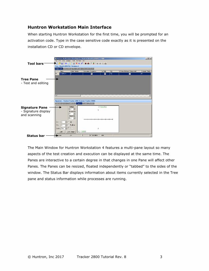
Huntron Workstation Main Interface
When starting Huntron Workstation for the first time, you will be prompted for an
activation code. Type in the case sensitive code exactly as it is presented on the
installation CD or CD envelope.
The Main Window for Huntron Workstation 4 features a multi-pane layout so many
aspects of the test creation and execution can be displayed at the same time. The
Panes are interactive to a certain degree in that changes in one Pane will affect other
Panes. The Panes can be resized, floated independently or “tabbed” to the sides of the
window. The Status Bar displays information about items currently selected in the Tree
pane and status information while processes are running.
Tree Pane
- Test and editing
Signature Pane - Signature display and scanning
Status bar
Tool bars
© Huntron, Inc 2017 Tracker 2800 Tutorial Rev. 8 4
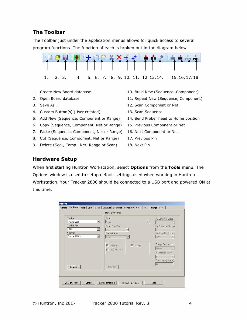
The Toolbar
The Toolbar just under the application menus allows for quick access to several
program functions. The function of each is broken out in the diagram below.
1. 2. 3. 4. 5. 6. 7. 8. 9. 10. 11. 12. 13. 14. 15. 16. 17. 18.
1. Create New Board database 10. Build New (Sequence, Component)
2. Open Board database 11. Repeat New (Sequence, Component)
3. Save As… 12. Scan Component or Net
4. Custom Button(s) (User created) 13. Scan Sequence
5. Add New (Sequence, Component or Range) 14. Send Prober head to Home position
6. Copy (Sequence, Component, Net or Range) 15. Previous Component or Net
7. Paste (Sequence, Component, Net or Range) 16. Next Component or Net
8. Cut (Sequence, Component, Net or Range) 17. Previous Pin
9. Delete (Seq., Comp., Net, Range or Scan) 18. Next Pin
Hardware Setup
When first starting Huntron Workstation, select Options from the Tools menu. The
Options window is used to setup default settings used when working in Huntron
Workstation. Your Tracker 2800 should be connected to a USB port and powered ON at
this time.
© Huntron, Inc 2017 Tracker 2800 Tutorial Rev. 8 5
For this tutorial, the Tracker 2800 will be referred to in general as “Tracker”.
Select the Hardware tab and set the type of Tracker hardware to Tracker 2800, the
Tracker Port (USB) and Scanner (if a Tracker 2800S is being used). Disregard the
Prober settings on the right side of the window.
Click the Connect button to initiate communication with the selected hardware. Once
connected, click the Save (Permanent) button to save this configuration as the
startup default. The Tracker 2800 will have “In Remote Mode” displayed on the LCD.
Using a Tracker 2800
The Tracker 2800 comes from the Factory calibrated for standalone use.
- Select Tools/Maintenance/Tracker 2800 Diagnostics from the menu.
Click the Alignment button. When the Alignment procedure finishes (about 10
minutes), run Verify Alignment. This also takes about 10 minutes to complete. The
Alignment information is stored in the Tracker 2800 and will be used by the software.
If changes are made to the cabling or attached instruments, simply run Alignment
and Verify Alignment again.
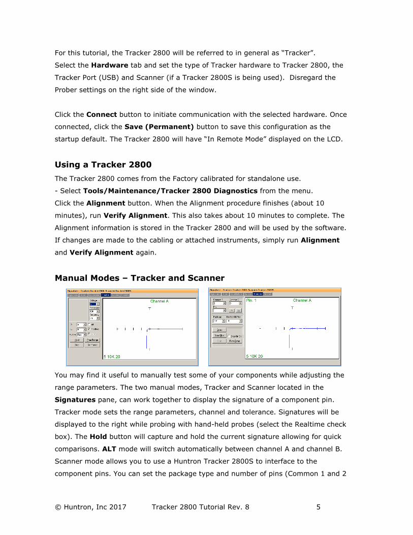
Manual Modes – Tracker and Scanner
You may find it useful to manually test some of your components while adjusting the
range parameters. The two manual modes, Tracker and Scanner located in the
Signatures pane, can work together to display the signature of a component pin.
Tracker mode sets the range parameters, channel and tolerance. Signatures will be
displayed to the right while probing with hand-held probes (select the Realtime check
box). The Hold button will capture and hold the current signature allowing for quick
comparisons. ALT mode will switch automatically between channel A and channel B.
Scanner mode allows you to use a Huntron Tracker 2800S to interface to the
component pins. You can set the package type and number of pins (Common 1 and 2
© Huntron, Inc 2017 Tracker 2800 Tutorial Rev. 8 6
are not supported by the Tracker 2800S). The Scan button starts a hands free scan of
the component through the scanner cable interface or you manually increment the
pins with the << and >> buttons. The Hold button will capture and hold the current
signature allowing for quick comparisons. Manual modes are for real time display only
and does not allow for permanent signature storage. To store signatures you will need
to create a Board Test.
Creating a Board Test
There are a number of steps necessary to creating a board test.
Example of Board Test Information:
Board Name: Main Board (creates “main board.hwdb” file)
Revision: Rev. A (This field is optional)
Sequence: IC’s
Component: U27 (component name) or A2 (NET name)
Pins: per pin settings for Scan Pin setting, channel, net name, etc…
Ranges: Per pin settings for common reference pin, tolerance, etc…
The user has total discretion as to the information input into these fields. There is no
“right” way as to what information is entered as every user’s situation will be different.
The above example is just one way the information might be entered.
Entering information into the Entry windows is very straight forward. The easiest way
to move from field to field is by pressing the TAB key. You can also use the mouse to
click into a particular field so you can enter information.
Test Building Procedures
- Create Test Database in the Tree Pane
o Add Board, Sequence, and Components before scanning
- Scan Components and Set References
Listed above is a general outline on how you would proceed when preparing to test a
board. These guidelines apply to all package types and boards. As with any type of
complex test equipment, practice makes perfect so take the time to learn and practice
these procedures.
© Huntron, Inc 2017 Tracker 2800 Tutorial Rev. 8 7
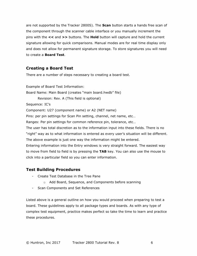
Creating a Board Database
To create a new Board, select New from the File menu or use the New button in the
toolbar. Input information into the “Add New Board” dialog as needed. The only field
that is required is board Name. Other fields such as Revision, System, Unit,
Manufacturer and Test Routine Number can be completed with related information if
desired.
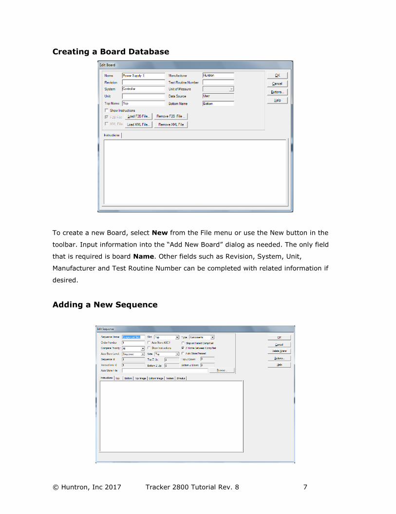
Adding a New Sequence
© Huntron, Inc 2017 Tracker 2800 Tutorial Rev. 8 8
To add a new Sequence, select the Sequence tab in the Tree pane. Select Add New
Sequence from the Edit menu or click the Add New button (+) in the toolbar.
Details:
Sequence Name Field: Enter Sequence name
Compare Priority: Selects the comparison priority between Same (serial number),
All (serial numbers; this is the recommended setting) or Merge (Merged min/max
signatures)
Instructions field: Enter any instructions or system information that you wish to
pass on to future users. Note: the ENTER key in this field will work as a carriage
return.
The Delete Scans button will delete all of the signature scans for the Sequence.
The Buttons… button will allow you to create a custom toolbar button that is attached
to the selected Sequence.
Other functions within this window can be read about by clicking the HELP button.
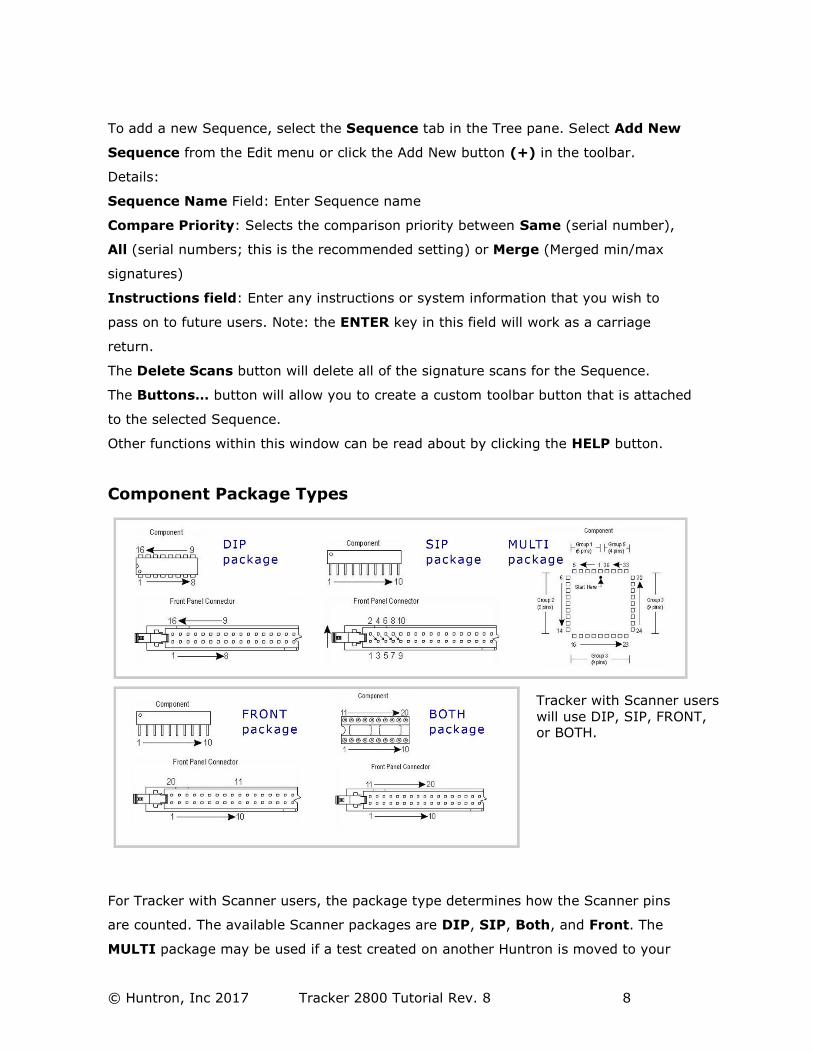
Component Package Types
For Tracker with Scanner users, the package type determines how the Scanner pins
are counted. The available Scanner packages are DIP, SIP, Both, and Front. The
MULTI package may be used if a test created on another Huntron is moved to your
Tracker with Scanner users
will use DIP, SIP, FRONT, or BOTH.
© Huntron, Inc 2017 Tracker 2800 Tutorial Rev. 8 9
Tracker 2800 system. The MULTI package will also be used for components created
using the CAD and/or HAF Import features.
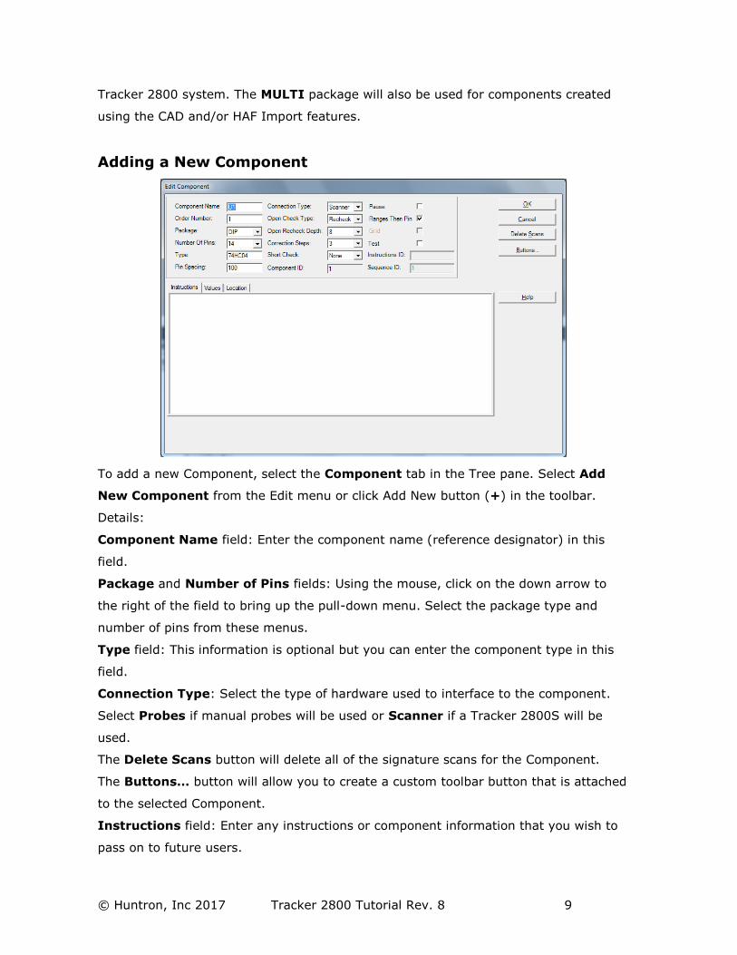
Adding a New Component
To add a new Component, select the Component tab in the Tree pane. Select Add
New Component from the Edit menu or click Add New button (+) in the toolbar.
Details:
Component Name field: Enter the component name (reference designator) in this
field.
Package and Number of Pins fields: Using the mouse, click on the down arrow to
the right of the field to bring up the pull-down menu. Select the package type and
number of pins from these menus.
Type field: This information is optional but you can enter the component type in this
field.
Connection Type: Select the type of hardware used to interface to the component.
Select Probes if manual probes will be used or Scanner if a Tracker 2800S will be
used.
The Delete Scans button will delete all of the signature scans for the Component.
The Buttons… button will allow you to create a custom toolbar button that is attached
to the selected Component.
Instructions field: Enter any instructions or component information that you wish to
pass on to future users.
© Huntron, Inc 2017 Tracker 2800 Tutorial Rev. 8 10
Other functions within this window can be read about by clicking the HELP button.
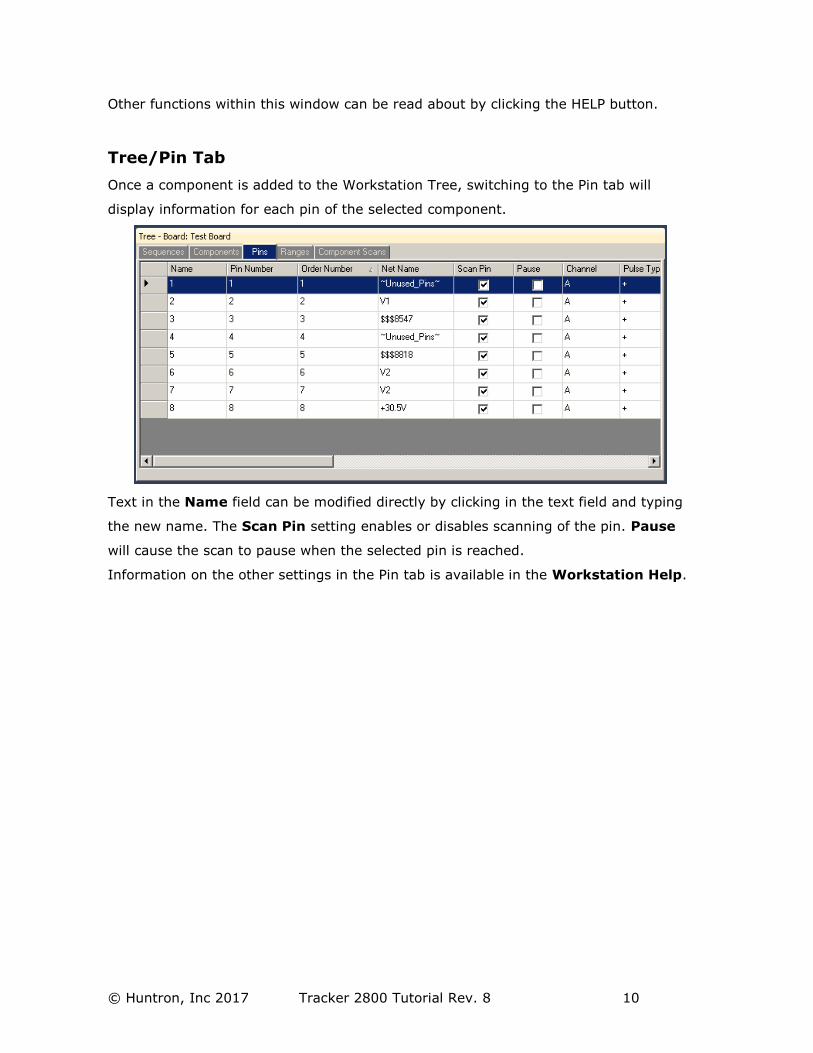
Tree/Pin Tab
Once a component is added to the Workstation Tree, switching to the Pin tab will
display information for each pin of the selected component.
Text in the Name field can be modified directly by clicking in the text field and typing
the new name. The Scan Pin setting enables or disables scanning of the pin. Pause
will cause the scan to pause when the selected pin is reached.
Information on the other settings in the Pin tab is available in the Workstation Help.
© Huntron, Inc 2017 Tracker 2800 Tutorial Rev. 8 11
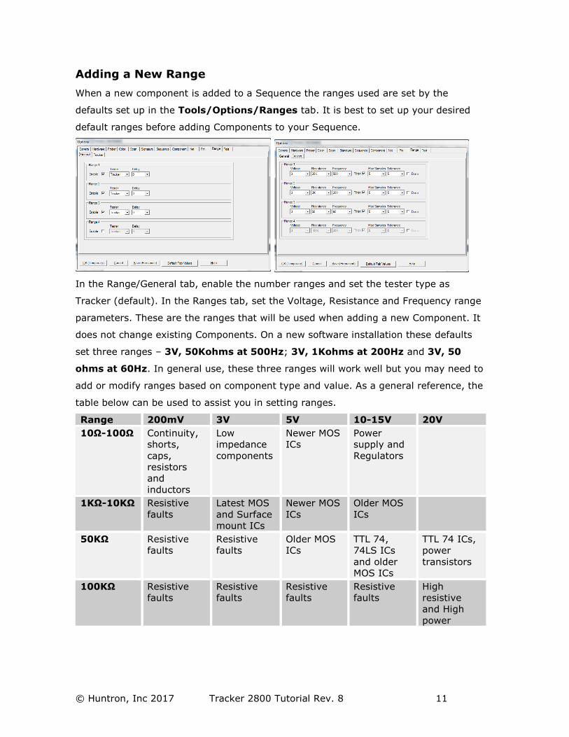
Adding a New Range
When a new component is added to a Sequence the ranges used are set by the
defaults set up in the Tools/Options/Ranges tab. It is best to set up your desired
default ranges before adding Components to your Sequence.
In the Range/General tab, enable the number ranges and set the tester type as
Tracker (default). In the Ranges tab, set the Voltage, Resistance and Frequency range
parameters. These are the ranges that will be used when adding a new Component. It
does not change existing Components. On a new software installation these defaults
set three ranges – 3V, 50Kohms at 500Hz; 3V, 1Kohms at 200Hz and 3V, 50
ohms at 60Hz. In general use, these three ranges will work well but you may need to
add or modify ranges based on component type and value. As a general reference, the
table below can be used to assist you in setting ranges.
Range 200mV 3V 5V 10-15V 20V
10Ω-100Ω Continuity,
shorts,
caps,
resistors
and
inductors
Low
impedance
components
Newer MOS
ICs
Power
supply and
Regulators
1KΩ-10KΩ Resistive
faults
Latest MOS
and Surface
mount ICs
Newer MOS
ICs
Older MOS
ICs
50KΩ Resistive
faults
Resistive
faults
Older MOS
ICs
TTL 74,
74LS ICs
and older
MOS ICs
TTL 74 ICs,
power
transistors
100KΩ Resistive
faults
Resistive
faults
Resistive
faults
Resistive
faults
High
resistive
and High
power
© Huntron, Inc 2017 Tracker 2800 Tutorial Rev. 8 12
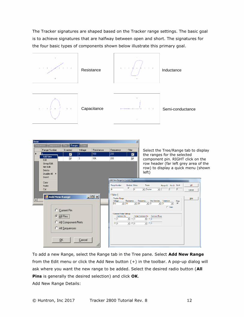
The Tracker signatures are shaped based on the Tracker range settings. The basic goal
is to achieve signatures that are halfway between open and short. The signatures for
the four basic types of components shown below illustrate this primary goal.
To add a new Range, select the Range tab in the Tree pane. Select Add New Range
from the Edit menu or click the Add New button (+) in the toolbar. A pop-up dialog will
ask where you want the new range to be added. Select the desired radio button (All
Pins is generally the desired selection) and click OK.
Add New Range Details:
Select the Tree/Range tab to display the ranges for the selected
component pin. RIGHT click on the row header (far left grey area of the row) to display a quick menu (shown
left)
Resistance
Capacitance
Inductance
Semi-conductance
© Huntron, Inc 2017 Tracker 2800 Tutorial Rev. 8 13
Note: Voltage/Resistance/Frequency can be modified directly in the Range grid.
Voltage/Resistance/Frequency fields: Select the desired range settings
Max Samples/Tolerance/Delay: Select the setting to be used when scanning this
range
Common Pin: Common pin selection is not available with the Tracker 2800S.
Note: It is easier to set up the ranges used by selecting Tools/Options/Range from
the Tools menu in the menu bar and pre-configuring the default ranges.
Scanning with a Tracker 2800 or Tracker 2800S
To scan an entire Sequence, select the Sequence in the Tree/Sequence tab. To scan an
individual component, select the component in the Tree/Component tab.
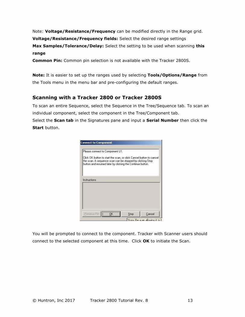
Select the Scan tab in the Signatures pane and input a Serial Number then click the
Start button.
You will be prompted to connect to the component. Tracker with Scanner users should
connect to the selected component at this time. Click OK to initiate the Scan.
© Huntron, Inc 2017 Tracker 2800 Tutorial Rev. 8 14
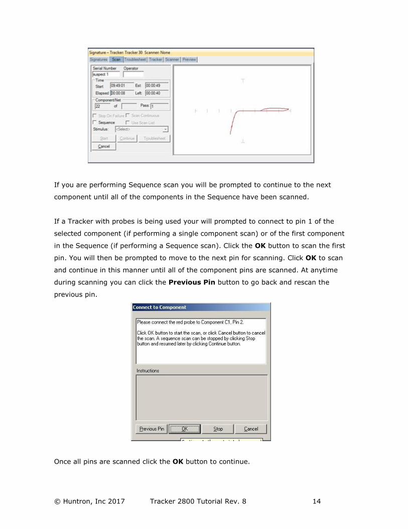
If you are performing Sequence scan you will be prompted to continue to the next
component until all of the components in the Sequence have been scanned.
If a Tracker with probes is being used your will prompted to connect to pin 1 of the
selected component (if performing a single component scan) or of the first component
in the Sequence (if performing a Sequence scan). Click the OK button to scan the first
pin. You will then be prompted to move to the next pin for scanning. Click OK to scan
and continue in this manner until all of the component pins are scanned. At anytime
during scanning you can click the Previous Pin button to go back and rescan the
previous pin.
Once all pins are scanned click the OK button to continue.

© Huntron, Inc 2017 Tracker 2800 Tutorial Rev. 8 15
When the Sequence or Component scan is complete the Scan Results window will be
displayed. Go to the Scan Results section of this tutorial for more information on
what to do after scanning.
Scan Results
When a scan is complete, the results PASSED, FAILED or NO REF will be displayed (the
text of the PASSED and FAILED message can be changed in the
Tools/Options/General settings). The NO REF message will be displayed on the first
scan of any test since there are no signatures stored as Reference.
Clicking the Troublesheet button will display the signature differences in the
Troublesheet tab of the Signature pane.
Note: Selecting the Troublesheet tab may display previous Troublesheet
information.
© Huntron, Inc 2017 Tracker 2800 Tutorial Rev. 8 16
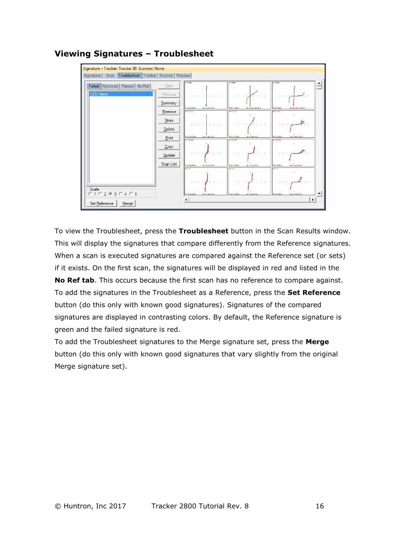
Viewing Signatures – Troublesheet
To view the Troublesheet, press the Troublesheet button in the Scan Results window.
This will display the signatures that compare differently from the Reference signatures.
When a scan is executed signatures are compared against the Reference set (or sets)
if it exists. On the first scan, the signatures will be displayed in red and listed in the
No Ref tab. This occurs because the first scan has no reference to compare against.
To add the signatures in the Troublesheet as a Reference, press the Set Reference
button (do this only with known good signatures). Signatures of the compared
signatures are displayed in contrasting colors. By default, the Reference signature is
green and the failed signature is red.
To add the Troublesheet signatures to the Merge signature set, press the Merge
button (do this only with known good signatures that vary slightly from the original
Merge signature set).
© Huntron, Inc 2017 Tracker 2800 Tutorial Rev. 8 17
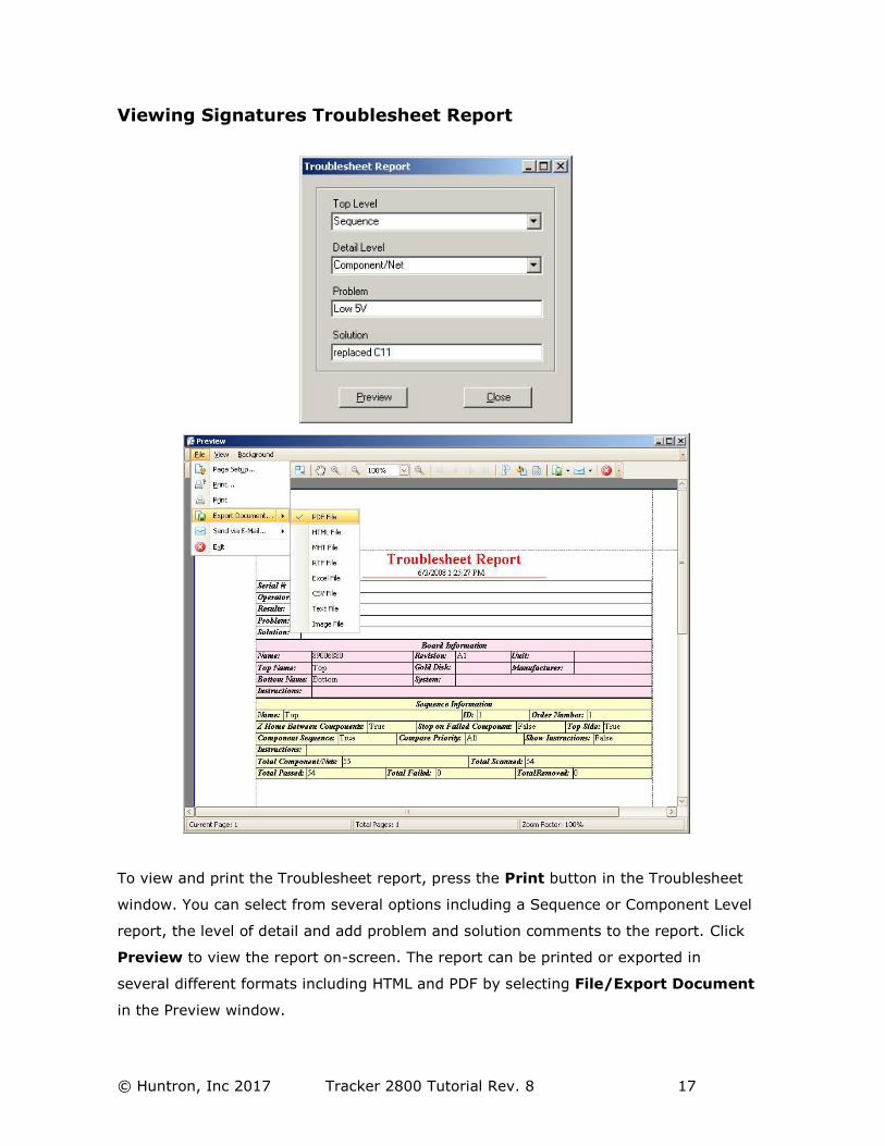
Viewing Signatures Troublesheet Report
To view and print the Troublesheet report, press the Print button in the Troublesheet
window. You can select from several options including a Sequence or Component Level
report, the level of detail and add problem and solution comments to the report. Click
Preview to view the report on-screen. The report can be printed or exported in
several different formats including HTML and PDF by selecting File/Export Document
in the Preview window.
© Huntron, Inc 2017 Tracker 2800 Tutorial Rev. 8 18
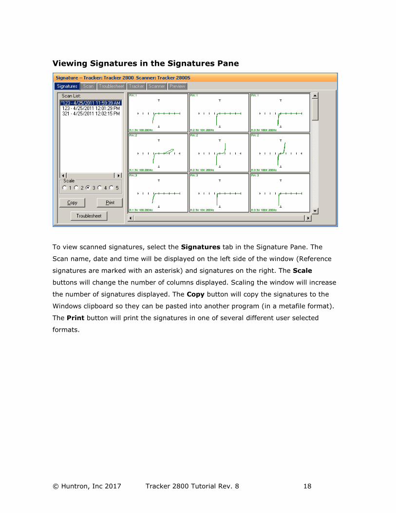
Viewing Signatures in the Signatures Pane
To view scanned signatures, select the Signatures tab in the Signature Pane. The
Scan name, date and time will be displayed on the left side of the window (Reference
signatures are marked with an asterisk) and signatures on the right. The Scale
buttons will change the number of columns displayed. Scaling the window will increase
the number of signatures displayed. The Copy button will copy the signatures to the
Windows clipboard so they can be pasted into another program (in a metafile format).
The Print button will print the signatures in one of several different user selected
formats.
© Huntron, Inc 2017 Tracker 2800 Tutorial Rev. 8 19
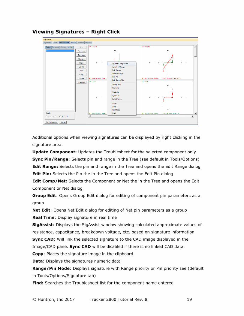
Viewing Signatures – Right Click
Additional options when viewing signatures can be displayed by right clicking in the
signature area.
Update Component: Updates the Troublesheet for the selected component only
Sync Pin/Range: Selects pin and range in the Tree (see default in Tools/Options)
Edit Range: Selects the pin and range in the Tree and opens the Edit Range dialog
Edit Pin: Selects the Pin the in the Tree and opens the Edit Pin dialog
Edit Comp/Net: Selects the Component or Net the in the Tree and opens the Edit
Component or Net dialog
Group Edit: Opens Group Edit dialog for editing of component pin parameters as a
group
Net Edit: Opens Net Edit dialog for editing of Net pin parameters as a group
Real Time: Display signature in real time
SigAssist: Displays the SigAssist window showing calculated approximate values of
resistance, capacitance, breakdown voltage, etc. based on signature information
Sync CAD: Will link the selected signature to the CAD image displayed in the
Image/CAD pane. Sync CAD will be disabled if there is no linked CAD data.
Copy: Places the signature image in the clipboard
Data: Displays the signatures numeric data
Range/Pin Mode: Displays signature with Range priority or Pin priority see (default
in Tools/Options/Signature tab)
Find: Searches the Troublesheet list for the component name entered
© Huntron, Inc 2017 Tracker 2800 Tutorial Rev. 8 20
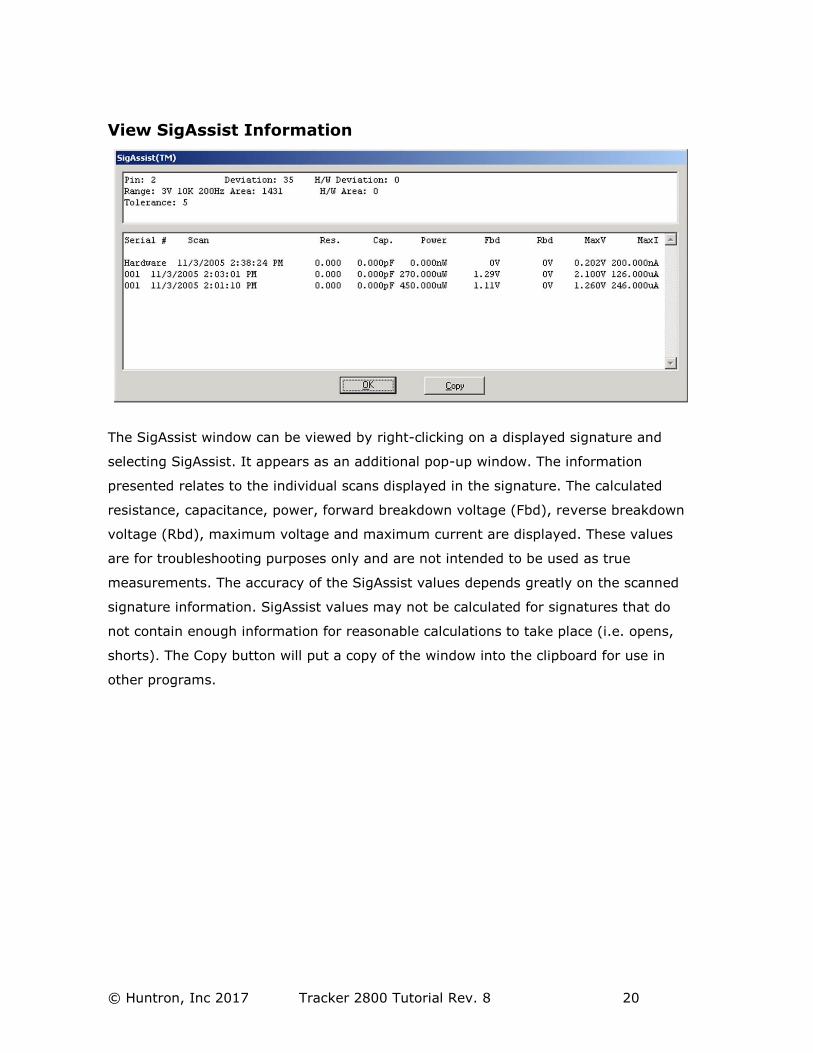
View SigAssist Information
The SigAssist window can be viewed by right-clicking on a displayed signature and
selecting SigAssist. It appears as an additional pop-up window. The information
presented relates to the individual scans displayed in the signature. The calculated
resistance, capacitance, power, forward breakdown voltage (Fbd), reverse breakdown
voltage (Rbd), maximum voltage and maximum current are displayed. These values
are for troubleshooting purposes only and are not intended to be used as true
measurements. The accuracy of the SigAssist values depends greatly on the scanned
signature information. SigAssist values may not be calculated for signatures that do
not contain enough information for reasonable calculations to take place (i.e. opens,
shorts). The Copy button will put a copy of the window into the clipboard for use in
other programs.
© Huntron, Inc 2017 Tracker 2800 Tutorial Rev. 8 21
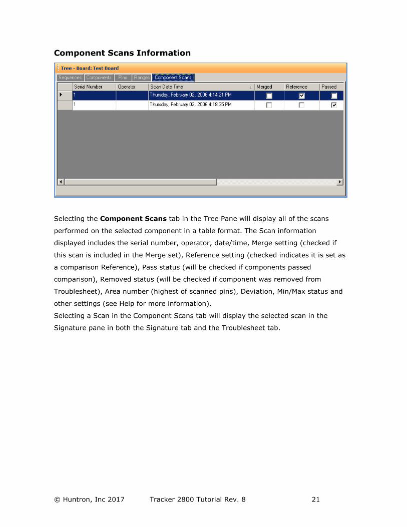
Component Scans Information
Selecting the Component Scans tab in the Tree Pane will display all of the scans
performed on the selected component in a table format. The Scan information
displayed includes the serial number, operator, date/time, Merge setting (checked if
this scan is included in the Merge set), Reference setting (checked indicates it is set as
a comparison Reference), Pass status (will be checked if components passed
comparison), Removed status (will be checked if component was removed from
Troublesheet), Area number (highest of scanned pins), Deviation, Min/Max status and
other settings (see Help for more information).
Selecting a Scan in the Component Scans tab will display the selected scan in the
Signature pane in both the Signature tab and the Troublesheet tab.
© Huntron, Inc 2017 Tracker 2800 Tutorial Rev. 8 22
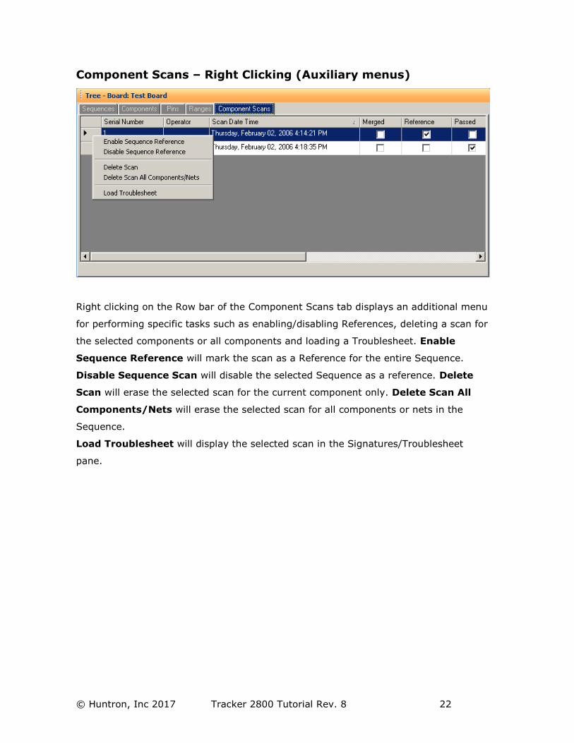
Component Scans – Right Clicking (Auxiliary menus)
Right clicking on the Row bar of the Component Scans tab displays an additional menu
for performing specific tasks such as enabling/disabling References, deleting a scan for
the selected components or all components and loading a Troublesheet. Enable
Sequence Reference will mark the scan as a Reference for the entire Sequence.
Disable Sequence Scan will disable the selected Sequence as a reference. Delete
Scan will erase the selected scan for the current component only. Delete Scan All
Components/Nets will erase the selected scan for all components or nets in the
Sequence.
Load Troublesheet will display the selected scan in the Signatures/Troublesheet
pane.
© Huntron, Inc 2017 Tracker 2800 Tutorial Rev. 8 23
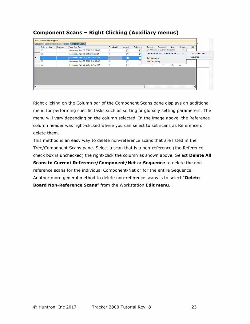
Component Scans – Right Clicking (Auxiliary menus)
Right clicking on the Column bar of the Component Scans pane displays an additional
menu for performing specific tasks such as sorting or globally setting parameters. The
menu will vary depending on the column selected. In the image above, the Reference
column header was right-clicked where you can select to set scans as Reference or
delete them.
This method is an easy way to delete non-reference scans that are listed in the
Tree/Component Scans pane. Select a scan that is a non-reference (the Reference
check box is unchecked) the right-click the column as shown above. Select Delete All
Scans to Current Reference/Component/Net or Sequence to delete the non-
reference scans for the individual Component/Net or for the entire Sequence.
Another more general method to delete non-reference scans is to select “Delete
Board Non-Reference Scans” from the Workstation Edit menu.
© Huntron, Inc 2017 Tracker 2800 Tutorial Rev. 8 24
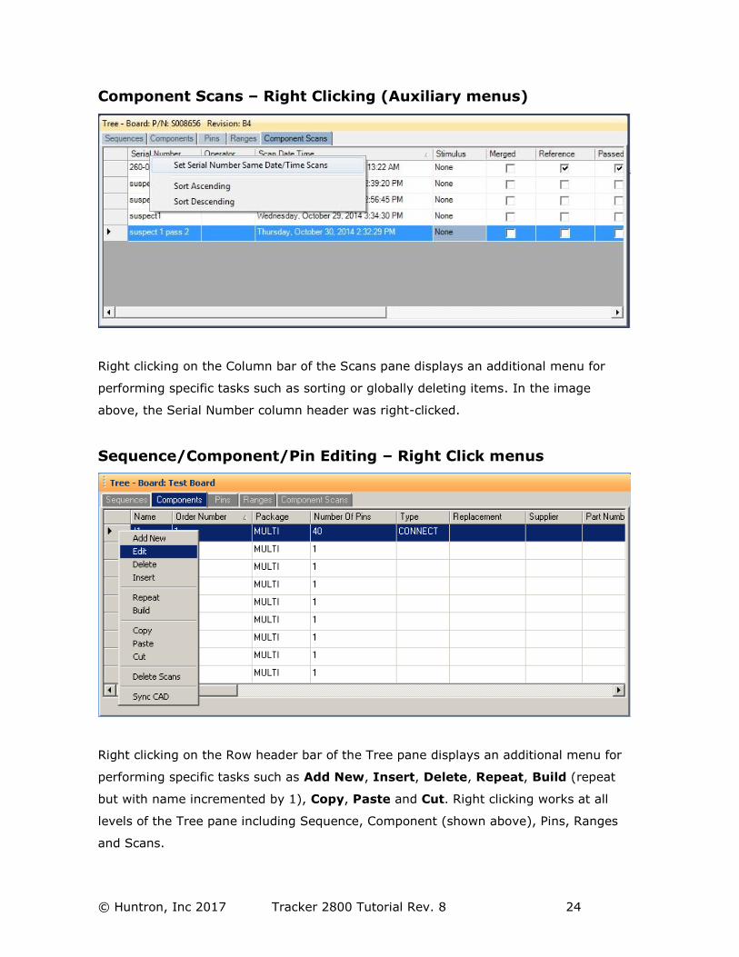
Component Scans – Right Clicking (Auxiliary menus)
Right clicking on the Column bar of the Scans pane displays an additional menu for
performing specific tasks such as sorting or globally deleting items. In the image
above, the Serial Number column header was right-clicked.
Sequence/Component/Pin Editing – Right Click menus
Right clicking on the Row header bar of the Tree pane displays an additional menu for
performing specific tasks such as Add New, Insert, Delete, Repeat, Build (repeat
but with name incremented by 1), Copy, Paste and Cut. Right clicking works at all
levels of the Tree pane including Sequence, Component (shown above), Pins, Ranges
and Scans.
© Huntron, Inc 2017 Tracker 2800 Tutorial Rev. 8 25
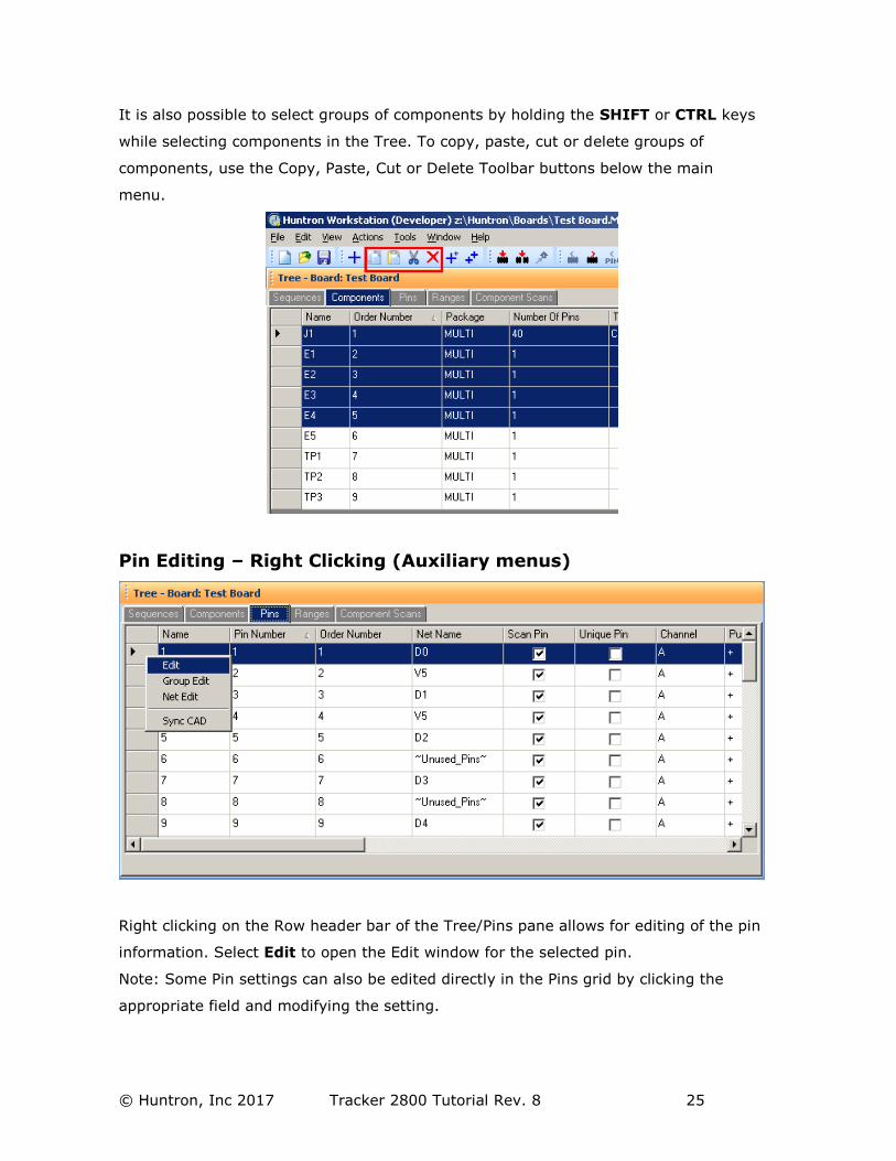
It is also possible to select groups of components by holding the SHIFT or CTRL keys
while selecting components in the Tree. To copy, paste, cut or delete groups of
components, use the Copy, Paste, Cut or Delete Toolbar buttons below the main
menu.
Pin Editing – Right Clicking (Auxiliary menus)
Right clicking on the Row header bar of the Tree/Pins pane allows for editing of the pin
information. Select Edit to open the Edit window for the selected pin.
Note: Some Pin settings can also be edited directly in the Pins grid by clicking the
appropriate field and modifying the setting.
© Huntron, Inc 2017 Tracker 2800 Tutorial Rev. 8 26
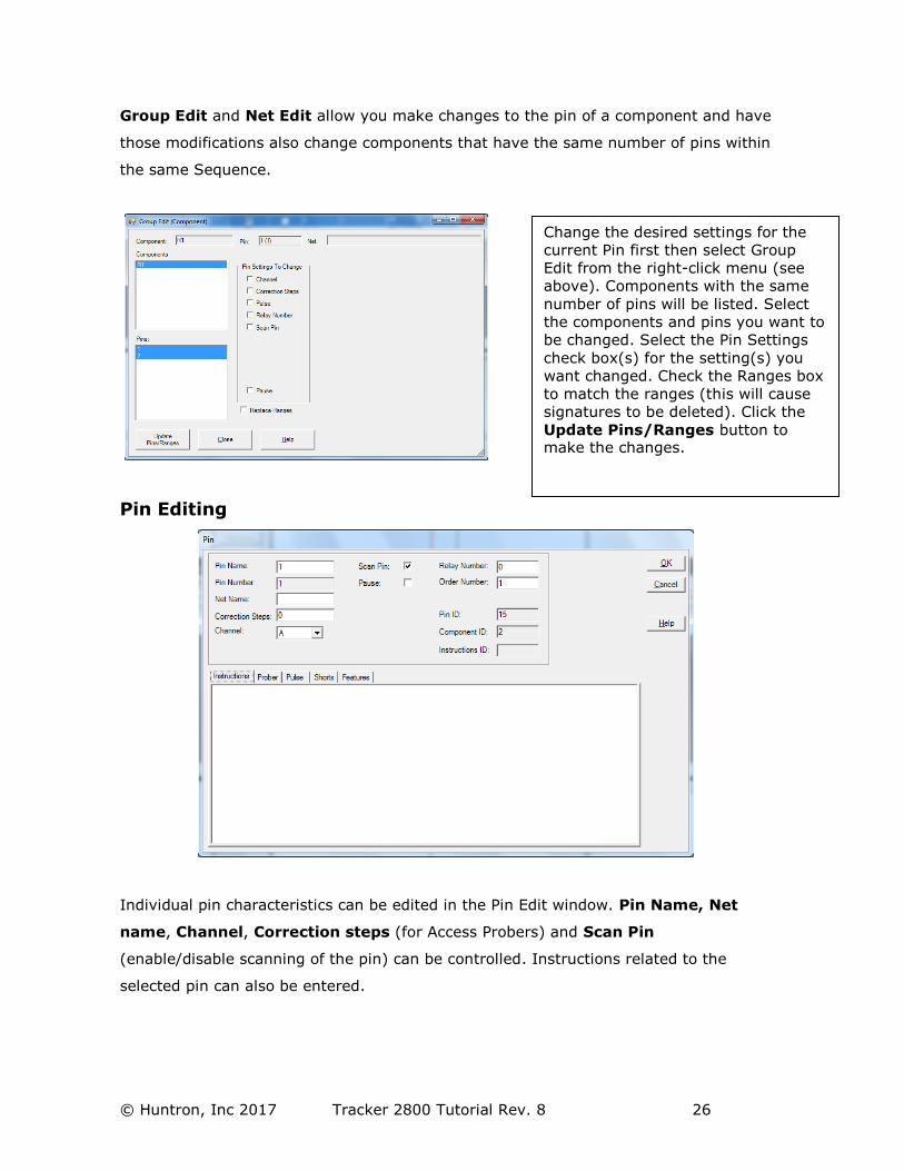
Group Edit and Net Edit allow you make changes to the pin of a component and have
those modifications also change components that have the same number of pins within
the same Sequence.
Pin Editing
Individual pin characteristics can be edited in the Pin Edit window. Pin Name, Net
name, Channel, Correction steps (for Access Probers) and Scan Pin
(enable/disable scanning of the pin) can be controlled. Instructions related to the
selected pin can also be entered.
Change the desired settings for the
current Pin first then select Group
Edit from the right-click menu (see
above). Components with the same
number of pins will be listed. Select
the components and pins you want to
be changed. Select the Pin Settings
check box(s) for the setting(s) you
want changed. Check the Ranges box
to match the ranges (this will cause
signatures to be deleted). Click the
Update Pins/Ranges button to make the changes.
© Huntron, Inc 2017 Tracker 2800 Tutorial Rev. 8 27
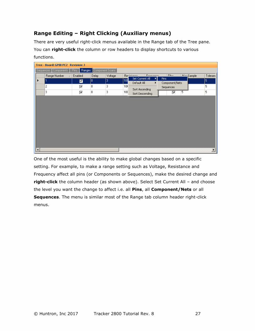
Range Editing – Right Clicking (Auxiliary menus)
There are very useful right-click menus available in the Range tab of the Tree pane.
You can right-click the column or row headers to display shortcuts to various
functions.
One of the most useful is the ability to make global changes based on a specific
setting. For example, to make a range setting such as Voltage, Resistance and
Frequency affect all pins (or Components or Sequences), make the desired change and
right-click the column header (as shown above). Select Set Current All – and choose
the level you want the change to affect i.e. all Pins, all Component/Nets or all
Sequences. The menu is similar most of the Range tab column header right-click
menus.
© Huntron, Inc 2017 Tracker 2800 Tutorial Rev. 8 28
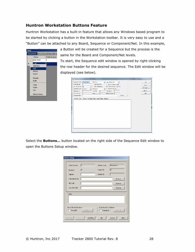
Huntron Workstation Buttons Feature
Huntron Workstation has a built-in feature that allows any Windows based program to
be started by clicking a button in the Workstation toolbar. It is very easy to use and a
“Button” can be attached to any Board, Sequence or Component/Net. In this example,
a Button will be created for a Sequence but the process is the
same for the Board and Component/Net levels.
To start, the Sequence edit window is opened by right-clicking
the row header for the desired sequence. The Edit window will be
displayed (see below).
Select the Buttons… button located on the right side of the Sequence Edit window to
open the Buttons Setup window.
© Huntron, Inc 2017 Tracker 2800 Tutorial Rev. 8 29
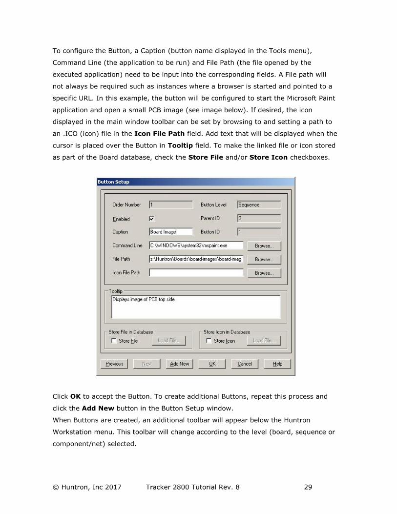
To configure the Button, a Caption (button name displayed in the Tools menu),
Command Line (the application to be run) and File Path (the file opened by the
executed application) need to be input into the corresponding fields. A File path will
not always be required such as instances where a browser is started and pointed to a
specific URL. In this example, the button will be configured to start the Microsoft Paint
application and open a small PCB image (see image below). If desired, the icon
displayed in the main window toolbar can be set by browsing to and setting a path to
an .ICO (icon) file in the Icon File Path field. Add text that will be displayed when the
cursor is placed over the Button in Tooltip field. To make the linked file or icon stored
as part of the Board database, check the Store File and/or Store Icon checkboxes.
Click OK to accept the Button. To create additional Buttons, repeat this process and
click the Add New button in the Button Setup window.
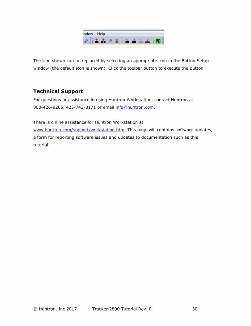
When Buttons are created, an additional toolbar will appear below the Huntron
Workstation menu. This toolbar will change according to the level (board, sequence or
component/net) selected.
© Huntron, Inc 2017 Tracker 2800 Tutorial Rev. 8 30
The icon shown can be replaced by selecting an appropriate icon in the Button Setup
window (the default icon is shown). Click the toolbar button to execute the Button.
Technical Support
For questions or assistance in using Huntron Workstation, contact Huntron at
800-426-9265, 425-743-3171 or email [email protected].
There is online assistance for Huntron Workstation at
www.huntron.com/support/workstation.htm. This page will contains software updates,
a form for reporting software issues and updates to documentation such as this
tutorial.