hushon (uk) ltd operation, maintenance & commissioning
TRANSCRIPT

Hushon (UK) Ltd – Operation, Maintenance & Commissioning Manual - Issue 11
www.hushonuk.co.uk 1
This manual provides detailed guidance on all aspects of health and safety, installation, commissioning and maintenance, which will be required at various stages. This manual covers all standard components, for certain specialist equipment such as controls, gas fired heaters and humidification equipment refer to the individual manufacturers instructions provided with the equipment and available on request. Should any further information or guidance be required do not hesitate to contact our office ensuring that you quote the unit (s) individual reference numbers.
Hushon (UK) Ltd, Unit A6, Railway Triangle Ind Est, Walton Rd, Portsmouth, PO6 1TN.
T: 023 92 324 335 / F: 023 92 324 348 / E: [email protected] / W: hushonuk.co.uk
Please ensure that a copy of this manual is left with the AHU (Air Handling Unit) upon completion of the project.
Spare Parts & Components We have a comprehensive range of spare parts available for immediate next day / same day delivery. A full spares fitting service is also available. All unit components and parts are detailed in the specific AHU drawing. For prices and any items not listed please do not hesitate to contact our office.

Hushon (UK) Ltd – Operation, Maintenance & Commissioning Manual - Issue 11
www.hushonuk.co.uk 2
Health and Safety 1. The AHU contains moving/rotating parts and under no circumstances should access be made whilst operational. 2. The AHU must be earthed and no installation or maintenance work should be attempted without first switching off and isolating from the electrical supply and allowing the rotating parts to come to rest. 3. The AHU is intended for moving air and is not suitable for use in environments for any other purpose than those specified in these instructions. If used improperly, or for different purposes without our prior agreement, then such use would be outside the scope of reasonably foreseeable circumstances, and may be unsafe. 4. It is the responsibility of the users to satisfy themselves that the AHU is suitable for the conditions of use, and that all works are carried out by personnel with the appropriate skills in line with these instructions and all good working practices. 5. It is essential that all works performed on this AHU are fully in accordance with the UK Health and Safety at Work Act and all other relevant directives and guidelines. 6. AHU access sections are manufactured to support the weight of one average weighted person standing on the unit floor. We can accept no responsibility for damage caused by excessive weight being applied. The AHU is not manufactured to withstand the weight of people standing on the top. AHU’s To Be Held In Storage If the unit is to be held in storage please take the following initial steps and the detailed maintenance instructions within this manual to maintain the unit during the period of non-operation. 1. Ensure that no undue stress is placed on the units in the form of ducting, silencers or other units. 2. Do not allow the AHU top to be used as a make shift workbench or a means of climbing to gain access to other areas of plant. 3. During the period of storage ensure that all air inlet/discharge points are sealed. This will prevent any dust properties or foreign bodies entering into the unit and protects all internal components from damage. 4. Remove all filters and wrap to protect from damp or dust. Filters should then be stored in dry conditions. 5. The unit would be supplied covered in a protective cling film wrapping to protect the unit during delivery and off-loading. It is advisable to leave this protective wrapping in place until the unit is commissioned. However this wrap is not intended to be used as a protection for long periods of time so something more permanent in the form of a tarpaulin should be deployed. 6. Units should be stored in a dry, clean and non-corrosive environment in temperatures between 10-20˚C.

Hushon (UK) Ltd – Operation, Maintenance & Commissioning Manual - Issue 11
www.hushonuk.co.uk 3
Off Loading & Positioning The following points should be followed to ensure successful off loading, positioning and installation of the AHU. 1. A visual inspection of the AHU should be carried out prior to off-loading and signing of the delivery note. Any damage to the AHU must be reported to our delivery operative at the time of delivery and a full description of any damage fully detailed on the job completion sheet as indicated. Any claims for loss or damage must be reported within 2 days of delivery. 2. All AHU’s are supplied with protective packaging to protect against weather conditions and damage to the exterior. The packaging should not be removed until the AHU is correctly in position to avoid any damage during positioning. 3. It is strongly advised that all off loading and positioning is carried out by specialist lifting personnel who will ensure that the correct lifting equipment is employed. All lifting and positioning must be in accordance with the relevant ‘Health And Safety At Work Act’ and the ‘Health And Safety Executive’ codes of practices. 4. Ensure that the AHU is lifted horizontally. 5. If the AHU is to be off loaded via the use of a forklift truck it is imperative that it is only lifted via the units base frame and that there is no pushing up of the base panels. The forks should be visible from the other side of the unit. 6. When a crane is used do not use metal slings. When using a sling to lift the unit lifting frames/beams must be used to ensure an even distribution of the units load and to maintain correct positioning of the slings. Place wooden packing pieces between the sling and the casework to prevent damage. The Pentapost framework or weather roof must not be used as a lifting point. 7. Where shown on the AHU drawing 50mm Dia Holes are drilled into the AHU base to allow lifting shackles to be fitted. Larger units are fitted with eye bolts fitted to the AHU base.
8. The AHU is only to be lifted from the base and no pressure is to be placed on the top, inlet, discharge or dampers. 9. No responsibility can be accepted for damaged caused during the off loading of the AHU. 10. Ensure that the AHU is mounted on a flat upright base and that adequate space is allowed to all access points. 11. All AHU’s are manufactured in line with industry standards and will achieve the standard air leakage test classifications. However due to the stresses incurred during off loading and positioning the AHU structures will inevitably move and interrupt the panel seals. It is therefore likely that re-sealing of panels and joints will be required
When a forklift is used, it should be ensured that the bottom of the unit will not be damaged if the forks are too short.
In order to avoid damage spacer rods / wooden packing pieces should be placed between the lifting straps and the unit to prevent twisting of the roof and framework.
Hushon (UK) Ltd – Operation, Maintenance & Commissioning Manual - Issue 11
www.hushonuk.co.uk 4
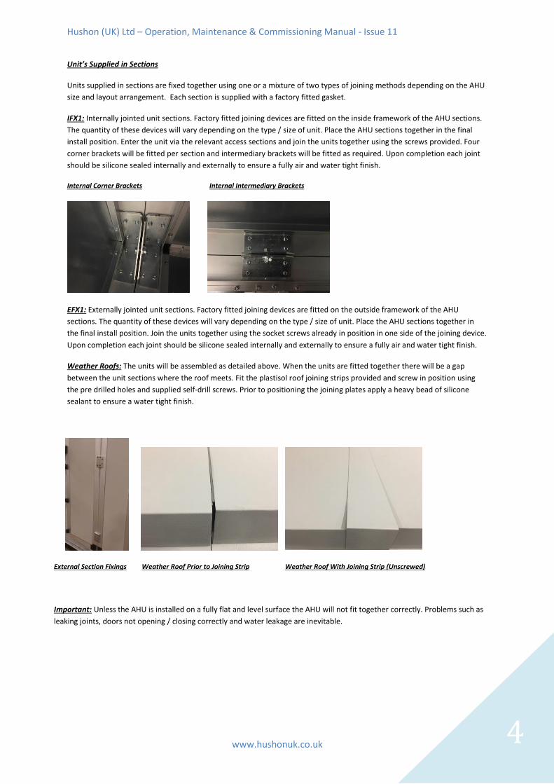
Unit’s Supplied in Sections
Units supplied in sections are fixed together using one or a mixture of two types of joining methods depending on the AHU
size and layout arrangement. Each section is supplied with a factory fitted gasket.
IFX1: Internally jointed unit sections. Factory fitted joining devices are fitted on the inside framework of the AHU sections.
The quantity of these devices will vary depending on the type / size of unit. Place the AHU sections together in the final
install position. Enter the unit via the relevant access sections and join the units together using the screws provided. Four
corner brackets will be fitted per section and intermediary brackets will be fitted as required. Upon completion each joint
should be silicone sealed internally and externally to ensure a fully air and water tight finish.
Internal Corner Brackets Internal Intermediary Brackets
EFX1: Externally jointed unit sections. Factory fitted joining devices are fitted on the outside framework of the AHU
sections. The quantity of these devices will vary depending on the type / size of unit. Place the AHU sections together in
the final install position. Join the units together using the socket screws already in position in one side of the joining device.
Upon completion each joint should be silicone sealed internally and externally to ensure a fully air and water tight finish.
Weather Roofs: The units will be assembled as detailed above. When the units are fitted together there will be a gap
between the unit sections where the roof meets. Fit the plastisol roof joining strips provided and screw in position using
the pre drilled holes and supplied self-drill screws. Prior to positioning the joining plates apply a heavy bead of silicone
sealant to ensure a water tight finish.
External Section Fixings Weather Roof Prior to Joining Strip Weather Roof With Joining Strip (Unscrewed)
Important: Unless the AHU is installed on a fully flat and level surface the AHU will not fit together correctly. Problems such as
leaking joints, doors not opening / closing correctly and water leakage are inevitable.

Hushon (UK) Ltd – Operation, Maintenance & Commissioning Manual - Issue 11
www.hushonuk.co.uk 5
Fan & Motor Sections Health & Safety Only operate the fan when it has a fixed means of isolation from the mains power supply (rotary isolator or similar). Body parts that come into contact with the rotor and impeller can be seriously injured. Before working on any part of the fan ensure that all parts have come to a complete standstill. Long hair, loose items of clothing and jewellery could become entangled and pulled into the fan. Do not wear any loose clothing or jewellery and protect long hair whilst working on any of the rotating parts. The fan is suitable for moving standard air only and is not suitable for any other purpose. The fan section is a high pressure chamber. Ensure the fan is isolated and come to a complete standstill before accessing the unit.

Hushon (UK) Ltd – Operation, Maintenance & Commissioning Manual - Issue 11
www.hushonuk.co.uk 6
Maintenance Instructions Maintenance of the ventilating equipment should only be carried out by skilled and fully trained engineers. To ensure complete safety do not start any maintenance procedure or inspection without having disconnected the fan / motor from the power supply and the fan and ensured all moving parts have completely stopped running. Ductwork Connection to the Fan Discharge All units unless otherwise stated are supplied with flanged ductwork connections to enable simple attachment to ducting. All ductwork should be independently supported. Fan Section Maintenance (approximately every 12 months) 1. Check that all fan/motor fixing points are securely fastened. Loose fixings require immediate attention. Do not use the same fixings to re-secure. 2. Ensure that there are no obstructions around the fan shaft/impeller. Remove any debris and clean. 3. Where fitted check to ensure that the flexible connection between the fan and the unit casing is in good condition. 4. Check for any corrosion and treat accordingly. 3 Phase AC Type Electric Motors All 3 phase induction motors are manufactured in accordance with strict quality control procedures have excellent functional and performance characteristics, and are of robust construction. To obtain optimum performance and service life from these motors please follow the instructions listed below. Power Connection The standard terminal box has 6 connection leads. The circuit links supplied, should be connected as per the below diagram.
MOTOR KW DOL STAR / DELTA INVERTER
0.18 – 3.0KW STAR - STAR
4.0 – 5.5KW DELTA - DELTA
7.5 - 90KW - STAR / DELTA DELTA
Motor Connected in Star Motor Connected in Delta

Hushon (UK) Ltd – Operation, Maintenance & Commissioning Manual - Issue 11
www.hushonuk.co.uk 7
Earthing / Grounding All motors must be earthed from the terminal marked “ground” in the terminal box. Protection The motors must be protected against short circuit, phase loss and overloads by fuse, thermal magnetic switches or electronic protection circuits. The nameplate values are valid for ambient temperatures up to 40oC and altitudes up to 1000m. The permissible supply voltage variation according to VDE 0530 is +/- 5% at the rated output and frequency. Commissioning Before starting the motor, please ensure that the following checks have been carried out: Wiring: Please refer to the motor nameplate for the method of connection. All motors are supplied with a connection diagram on the inside of the terminal box lid or on the motor nameplate. Ensure the motor is connected in the correct manner for the starting method. All motors are provided with a spacious terminal box mounted on top of the motor. Starting: When a motor is operated for the first time check the direction of rotation is correct and that everything runs freely. To reverse the direction of rotation interchange any 2 of the 3 supply leads. Thermistors: They are fitted as standard to all AC motors. Troubleshooting Complete the following check list to solve problems encountered with the motor. 1. Motor will not start: Check for correct voltage at motor terminals. Ensure that the motor and load are free to turn. Check that contactors operate. 2. Starter trips out on starting or the motor starts but has no torque or is overheating. Check for wrong or loose connections. Check overload settings. Check current drain against rated current for full load. Check voltage at motor terminals (Possibly low voltage due to voltage drop on long cabling or incorrectly sized cabling. Check connections (star / delta). Check all three phases are connected correctly. 3. All 3 phases have been checked and they are OK. Has a voltmeter been used as test lamps / neon testers can sometimes pick up voltages coming back through the windings to other terminals. Check for correct voltage with a DVM (Digital Voltage Meter). If the motor is found to be noisy there are two basic scenarios (assuming nothing obvious such as loose or interfering parts). 1. Motor may sound rough one to one phase going out. Note that the motor will not re-start if phase has gone down (single phased) and will ultimately burn out if left in this state for too long. Check for voltage on all 3 phase connections – possible connection / contactor fault. 2. If noise is mechanical it may be bearing related – very noticeable under load – can also be heard as a rattle when coming to rest off-load. Summary AC Motors usually run – period. If they fail, it is terminal and usually shows up early in the life of the motor if it is a manufacturing fault. Excessive current is normally a connection problem. Inverter Speed Controllers All AC motors on plug fans must be operated by a variable frequency drive (VFD / Inverter). Whether this item is supplied by ourselves or by others it is often necessary to run the inverters above 50Hz. The AHU drawing states the design speed in hertz and the maximum permissible speed in hertz. The maximum hertz level is also printed on the fan data label on the fan casework.

Hushon (UK) Ltd – Operation, Maintenance & Commissioning Manual - Issue 11
www.hushonuk.co.uk 8
Plug Fan Motor Replacement (Large Applications). These details are generic for a typical application and are for guidance purposes only. Certain applications may have specialist requirements. Ensure the power is isolated, and disconnect motor wiring. Before starting, if a new motor is being fitted, check condition and check that key connection aspects, eg motor frame size, terminal box position, cable glands etc. are compatible without additional parts or modification. Check that the motor Kw rating, polarity etc. is the same as existing. If not, please check before proceeding. 1) Ensure motor is electrically isolated at the AHU, switched off at the control panel panel and padlocked off on the breaker. 2) Disconnect the motor from all supply cables, noting down the colours of cables and their respective terminals. 3) Measure and record clearances between impeller shroud and inlet cone at 90degree points, marking with a pen. We recommend the use of feeler gauges inserted into the gap between impeller shroud and inlet cone, at cardinal points ie 12 O’ clock 3, 6 & 9 O’clock. The impeller should have the keyway pointing up to 12 O’ clock when measuring. The purpose of this is to have a reference set of figures to ensure the correct tip gap is attained when the new motor has been fitted. 4) Dismount inlet flexible connection, by removing nuts and bolts between flexible flange and inlet cone upstand, and flexible flange and bulkhead. Note two people required, one either side of bulkhead. 5) Mark the position of the inlet cone upstand on the base frame by marking around the upstand to base frame interface, to ensure upstand is mounted in the exact same position when re-mounting. Unbolt upstand from base frame, then dismount inlet cone. 6) Remove the fan access door by unbolting hinge from door frame. Then remove the outer fixed panels above and panel beside to give access accordingly. For door removal unscrew door hinges whilst supporting door and then lift off. For fixed panels remove internal tec screws (7mm driver bit required) and carefully slice silicone seal with a knife before gently tapping panel from the inside with a mallet (rubber) to break any remaining silicone seal and lift out panels. *Where panels have any electrical equipment mounted disconnect wiring and remove the electrical item before attempting to remove panels. 7) Assemble lifting gantry with one support leg inside AHU, and the other leg outside AHU, ensuring gantry beam is level. Note scaffold planks or similar laid on the AHU floor are required to spread the load and prevent damage to the AHU floor. Lifting gantry type we would recommend would be from Speedy lifting hire services. An intermediate A frame alloy gantry product code 70/6015-h, which comes complete with a girder trolley. The lever arm chain hoist required from speedy is the 500Kg SWL product code70/9715-h. Slings are to buy only from Speedy Lifting Hire Services, we recommend a pair of 1 tonne SWL 1 metre web slings product code C1002003-s. Bow shackles, a pair of 2 tonne bow shackles product code 72/8205-h. 8) Fit girder trolley to gantry, lifting gear and strops to support the weight of the impeller, in readiness for removal. The slings should be looped through the impeller blades close to the back plate so that the centre of gravity is maintained when lifting.
70/6015-h

Hushon (UK) Ltd – Operation, Maintenance & Commissioning Manual - Issue 11
www.hushonuk.co.uk 9
90/9715-h C1002003-s
72/8205-h
9) Before dismounting the impeller, measure the distance from the end of the shaft to the impeller hub, making a note of the dimension, so that the impeller can be re-fitted in the exact same position. Dismount the impeller from motor shaft using the taper lock fitting. To dismount the taper lock bush which holds impeller to shaft, loosen off and remove both grub screws (using allen key either 8 or 6mm). Then re-fit one grub screw into the “third hole” and tighten up, which should push the hub off the bush. If the hub does not move, then gently tap the hub (not impeller) with a copper/rawhide mallet opposite the grub screw. Once the hub has moved off the bush by 2-3 mm, the impeller can then be slid off the shaft. Take the weight of the impeller on the chain hoist, then gently ease the impeller off the shaft, and remove from AHU. 10) Motor removal – position chain hoist above motor. Loop lifting sling through motor lifting lugs and hook onto chain hoist, taking up slack. Mark the position of motor feet on the pedestal with a marker pen to ease centralisation of new motor. Unbolt motor feet from pedestal. Lift motor on chain hoist to clear pedestal before removing from AHU. 11) Dismount the motor from the motor pedestal. To refit with new or repaired motor, follow above steps from 8 to 3 in reverse. Then; a) Check impeller to shroud tolerances are maintained with records taken from 3, adjusting taper lock as required. b) Reconnect motor to electrical supply. c) Check impeller and motor assembly is balanced to grade G2.5, rebalancing if required. (power required). d) Ideally leave records of any changes and the service permanently attached to fan next to nameplate. e) Refit panels and door, sealing accordingly to ensure section is air tight.

Hushon (UK) Ltd – Operation, Maintenance & Commissioning Manual - Issue 11
www.hushonuk.co.uk 10
Heating / Cooling Coil’s / Condensate Drain Connections Installation 1. When connecting the coil flow / return pipe work it is imperative that they are connected in the correct sequence. Fluid heating and cooling coils and steam heating coils should be connected as detailed below. For DX refrigerant coils refer to the AHU general arrangement drawing.
2. Care should be taken when installing connecting pipe work as twisting of the coil connections can easily occur. Where possible a pipe wrench should be used to ensure that twisting does not occur. Maintenance 1. Remove dusty dry coil surfaces using either compressed air with care, preferably in counter flow to the normal air-flow direction, a vacuum liner or by using a cloth and neutral solution. If greasy dust deposits appear these can be removed either by using a high pressure steam line or by washing in a neutral solvent. 2. Inspect all metal work, casing and drain tray for signs of corrosion or deterioration. Remove any rust spots and paint where necessary. Inspect all connecting pipe work to ensure that there are no leaks. Condensate Drain Connections Correct installation of the drain trap is essential to prevent water flowing back into the drain pan and then into the AHU casing and other surrounding areas. The drain line size should not be less than the connection from the AHU drain pan (25mm / 1” BSP standard). The drain line should slope downwards at a fall of not less than 10mm per metre and should be terminated at a suitable tundish or other break. Installation: Ensure the trap is filled prior to the initial starting of the AHU. Maintenance: The trap should never be allowed to dry out. Check the drain and drain pan for leaks / blockages and remedy as required. See sketches below for recommended arrangements.
Heating &
Cooling Water
Coils
(Heat & Cool)
Steam Heating
Coils
Draw Through - Negative Pressure Applications (-) Blow Through - Positive Pressure Applications (+)
TSP = Total suction pressure in (Pa)
based on filter dirty conditions.
A= TSP / 10 + 50mm
B= A / 2 minimum
A & B = Total trap height
TDP = Total discharge pressure in (Pa)
based on filter dirty conditions.
A= 50mm minimum
B= TDP / 10 + 50mm
A & B = Total trap height
Typical example (Negative -)TSP
= 700Pa
A= (700 / 10) + 50mm = 70 +
50 = 120mm
B= 120 / 2 = 60mm
Overall trap height (A & B) =
180mm
Draw Through Blow Through

Hushon (UK) Ltd – Operation, Maintenance & Commissioning Manual - Issue 11
www.hushonuk.co.uk 11
Filter Sections
Filtration Installation All filter sections are supplied with galvanized steel slide frames or front withdrawal frames and P clips to enable easy filter installation. Most panel, bag and carbon filters are supplied fully installed within the AHU on delivery. Some high grade bag filters and all HEPA filters are supplied in a fully packaged cardboard container to prevent damage during installation. Take extreme care when installing HEPA and rigid bag filters not to damage the filter media, as any damage will affect the performance of the filter. Damage to HEPA filters is irreparable and will require replacement. When installing bag filters it is essential that the bag is installed in the correct position with the pocket vertical / upright. Incorrect installation will lead to the collapse of the bags and prevent the required airflow from being achieved. If the bag filters are dropped or thrown during installation they should be checked for damage to the media prior to being installed. Filtration Maintenance Panel and bag filters should be replaced when the pressure exceeds the recommended levels as stated in the specific AHU drawing. Replacement of filters is a simple process, open the filter access panel and remove the dirty filters. Replace the filters ensuring that the replacement filters match in terms of both size and efficiency (Precise details of filter sizes and efficiencies are detailed on the specific AHU drawing. When installing the replacement filters it is essential that they are installed in the correct position as per the airflow arrow. Filter Gauges No lubrication or periodic servicing is required. Keep the cover clean. Occasionally disconnect pressure lines to vent both sides of the gauge to atmosphere and re-zero.
Hushon (UK) Ltd – Operation, Maintenance & Commissioning Manual - Issue 11
www.hushonuk.co.uk 12
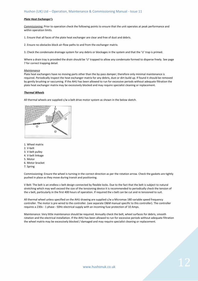
Plate Heat Exchanger’s Commissioning: Prior to operation check the following points to ensure that the unit operates at peak performance and within operation limits. 1. Ensure that all faces of the plate heat exchanger are clear and free of dust and debris. 2. Ensure no obstacles block air-flow paths to and from the exchanger matrix. 3. Check the condensate drainage system for any debris or blockages in the system and that the ‘U’ trap is primed. Where a drain tray is provided the drain should be ‘U’ trapped to allow any condensate formed to disperse freely. See page 7 for correct trapping detail. Maintenance Plate heat exchangers have no moving parts other than the by-pass damper; therefore only minimal maintenance is required. Periodically inspect the heat exchanger matrix for any debris, dust or dirt build up. If found it should be removed by gently brushing or vaccuming. If the AHU has been allowed to run for excessive periods without adequate filtration the plate heat exchanger matrix may be excessively blocked and may require specialist cleaning or replacement. Thermal Wheels All thermal wheels are supplied c/w a belt drive motor system as shown in the below sketch.
1. Wheel matrix 2. V-belt 3. V-belt pulley 4. V-belt linkage 5. Motor 6. Motor bracket 7. Spring Commissioning: Ensure the wheel is turning in the correct direction as per the rotation arrow. Check the gaskets are tightly pushed in place as they move during transit and positioning. V Belt: The belt is an endless v belt design connected by flexible locks. Due to the fact that the belt is subject to natural stretching which may well exceed the size of the tensioning device it is recommended to periodically check the tension of the v belt, particularly in the first 400 hours of operation. If required the v belt can be cut and re tensioned to suit. All thermal wheel unless specified on the AHU drawing are supplied c/w a Micromax 180 variable speed frequency controller. The motor is pre wired to the controller. (see separate O&M manual specific to this controller). The controller requires a 230v - 1 phase - 50Hz electrical supply with an incoming fuse protection of 10 Amps. Maintenance: Very little maintenance should be required. Annually check the belt, wheel surfaces for debris, smooth rotation and the electrical installation. If the AHU has been allowed to run for excessive periods without adequate filtration the wheel matrix may be excessively blocked / damaged and may require specialist cleaning or replacement.

Hushon (UK) Ltd – Operation, Maintenance & Commissioning Manual - Issue 11
www.hushonuk.co.uk 13
Electric Heaters
General: Sheathed element air heaters provide a safe means of heat transfer using electricity. Touching the elements will
not produce an electric shock.
Control System: A suitable control scheme should be provided and should include a timer to keep the fan running for a
minimum 2 minutes after the heater has been shut off. ALWAYS ENSURE THAT AN AIRFLOW OR PRESSURE SWITCHED IS
USED TO SHUT DOWN THE HEATER IN THE VENT OF AN AIR-FLOW FAILURE. Speed Controls: Please ensure that when the
heater is commissioned that allowance is made to ensure that the unit airflow is not reduced below the minimum velocity
permitted over the electric heater. The minimum safe face velocity is 2.0m/s and they should not be operated below this.
Always fit a local isolator for maintenance of the electric heater. Maintenance: Check all cabling and terminations are in
good condition.
Thermal Cut Out (TCO): The heater is fitted with a manual safety cut out which will cut out if the safety limit is reached.
This has normally closed terminals. The stat is set to 125°C as standard. The stat should be connected in series with the
main contactor coil circuit to isolate the heater in the event of an airflow failure.
Cables should be silicone rubber, fibre glass or similar high temperature insulated type or to current I.E.E regulations. For
cable routing drill the sides, top or base of the heater casework and ensure appropriate glands are used
3 phase heaters are star point connection and no neutral is required.
The below diagram and photograph is for a typical three phase single stage electric heater. Where additional steps are
supplied each step will be a duplicate of the below however there will be only one thermal cut out. For single phase
heaters there will be a live (L1) and neutral (N1) connection.

Hushon (UK) Ltd – Operation, Maintenance & Commissioning Manual - Issue 11
14
General Maintenance Checks Access Sections / Access Panels Open the unit access doors to ensure that an airtight seal remains between the unit panel and framework. Access doors found to be leaking air will require treating by fitting a new section of door sealant rubber around the internal edge of the access panel. General Casework Regular inspection of the unit should be carried out to ensure that there is no corroding or damage of the unit panels or base frame. The occurrence of “white rust” (zinc oxide) on galvanized steel is a normal event and not a maintenance issue. This occurs when the zinc in the galvanizing reacts electrolytically with moisture to protect the steel. Weather Louvres And Inlet/Discharge Weather Cowls Ensure that no debris such as insects and leaves have congregated on the protective mesh. Remove any obstructions. Dampers Ensure that the damper blades turn freely and remove any debris, which may have congregated. Treat the damper mechanisms with a greaseproof compound to ensure free mobility of the blades. Electrical Wiring And Connections An annual inspection should be carried out on all electrical equipment by a fully qualified electrical person. Door Guard Maintenance Where fitted check the guard for wear or damage. Clean the guard / repair as required. Filter Gauges, Actuators & Other Controls For any specific information on filter gauges or any other type of controls contact our office. Other For any other maintenance issues please contact our office. Attenuators / Attenuator Pods Attenuators have no moving parts and therefore require no lubrication or routine maintenance. Check for any corerosion and treat as necessary. Recommended Inspection Periods Every 1-3 Months: Filters Every 3 Months: Fan impeller rotating freely Every 6 Months: Coils Every 12 months: Check the workings of all components and service as detailed within this manual

Hushon (UK) Ltd – Operation, Maintenance & Commissioning Manual - Issue 11
15
Commissioning Guidelines 1. Ensure that the installation is fully complete, all tools / keys etc have been removed from the unit and that all electrical connections fully comply with local by laws and regulations. 2. Check all coil connections to ensure that no leakage is occurring. Allow water to flow into the coil drain trays to ensure that all the water is sufficiently drained. 3. When operational check the correct rotation of the fan. Ensure there is no overheating of the bearings. 4. Check all unit joints and panels to ensure that there is no leakage occurring. 5. Adjust any fitted dampers accordingly. 6. Check that the unit airflow rate and resistance are as per the specified unit design criteria. 7. Ensure that the amps drawn by the motor are as per the amp level stated on the motor nameplate situated on the side of the motor. 8. Check that the coil inlet/outlet temperatures and flow rates are correct and adjust as required. 9. Check the electric heater to ensure that the correct heat output is achieved and check to ensure that the heater safely turns off in the event of an air-flow failure in conjunction with the units controls system. Troubleshooting Tips And Guidelines Please use the following troubleshooting guide to solve any problems with the unit. If the problem is not listed or the recommended solution does not work do not hesitate to contact our office. 1. The unit will not operate although the power is on and no apparent electrical fault can be found. Check all controls equipment / overloads etc used to operate the unit and remedy any faults accordingly. 2. There is evidence of water spillage inside the unit casing. Check all coil pipe work to ensure that there are no leaks occurring. Any leak must be remedied immediately by a fully qualified plumber / pipe engineer. Check the condensate trap installation is correct. 3. The unit is over performing. A thorough check of the whole system should be carried out ensuring that all ductwork is complete, and that all dampers are correctly positioned. A measurement of the external static pressure level should be carried out to ensure that it is as design. 4. The unit is under performing. Check for blockages in the duct system. Check filters for blockages. Measure the external static pressure level to ensure the level is as per the original design level. 5. The motor is absorbing excessive ampage levels / The motor has tripped out The unit may be over performing (see above). The unit may have been wired incorrectly. The motor may be damaged. The electrical supply may be un-balanced. See motor troubleshooting. 6. There are excessive vibrations from the fan section. Check for any foreign items such as tools or debris. Check that the fan impellor is properly balanced. Check for damage to the anti vibration mountings. Ensure transport brackets have been removed. 10. There is excessive noise from the unit. Check the bearings for damage. Ensure that all panel seals are fully secure. 11. The filter cells have collapsed. The cells may be excessively blocked with dirt. Water ingress may have caused damage. 12. The heating coil is not achieving its required design performance. Ensure that the medium temperatures are at the correct design temperature. Check the medium flow rates. Check for any debris / blockages across the coils face area. 13. The cooling coil is not achieving its required design performance. Ensure that the medium temperatures are at the correct design temperature. Check the medium flow rates. Check for any debris across the coils face area. 14. There is condensate leaking from the AHU base. Check that the condensate trap has been correctly installed. The unit volume may be higher than original designed. 15. The electric heater battery is not achieving the required performance. Check to ensure that the elements have not burnt out and that the high limit thermostat has not cut out. Warranty: Full warranty information is available from our office on request. The following points should be considered as failure to comply may affect any warranties.
1. Only authorized and fully trained personnel are to have access to the air handling unit and any associated equipment supplied by the company. 2. No responsibility can be accepted for the air-handling unit if non-recommended parts are installed into any section of the unit. 3. Ensure that the unit is free of all personnel prior to securing unit panels. 4. Keys required for access to the unit must be kept in a safe place and by a fully competent person. 5. Electrical work is only to be performed by fully qualified electrical personnel.
Declaration Of Conformity ‘Hushon (UK) Ltd’ declares that all equipment supplied by the company in relation to the project detailed within this manual is in full
compliance with all relevant ‘health and safety requirements’.