hustler zeon operator’s manual - · pdf filerev f 1-4 112479_0612 warranties of...
TRANSCRIPT

112479_0612 REV F
Hustler ® ZeonOperator’s Manual
•••••P.O. Box 7000
•••Hesston, Kansas
•67062-2097

REV F 112479_0612

1124799_0612 toc-1 REV F
Table of Contents
General Information . . . . . . . . . . . . . . . . . . . . . . . . . . . . . . . . . . . . . 1-1
To the new owner . . . . . . . . . . . . . . . . . . . . . . . . . . . . . . . . . . . . 1-1
Using this manual . . . . . . . . . . . . . . . . . . . . . . . . . . . . . . . . . . . . 1-1
Warranty registration . . . . . . . . . . . . . . . . . . . . . . . . . . . . . . . . . 1-1
Model and serial number . . . . . . . . . . . . . . . . . . . . . . . . . . . . . . 1-1
Parts and service . . . . . . . . . . . . . . . . . . . . . . . . . . . . . . . . . . . . 1-1
Safety Precautions. . . . . . . . . . . . . . . . . . . . . . . . . . . . . . . . . . . . . . 2-1
Operation . . . . . . . . . . . . . . . . . . . . . . . . . . . . . . . . . . . . . . . . . . . . . 3-1
Safe Operating Practices . . . . . . . . . . . . . . . . . . . . . . . . . . . . . . 3-1
Operation . . . . . . . . . . . . . . . . . . . . . . . . . . . . . . . . . . . . . . . . . . 3-1
Using a ramp . . . . . . . . . . . . . . . . . . . . . . . . . . . . . . . . . . . . . . . 3-2
Slope operation . . . . . . . . . . . . . . . . . . . . . . . . . . . . . . . . . . . . . 3-2
Children . . . . . . . . . . . . . . . . . . . . . . . . . . . . . . . . . . . . . . . . . . . 3-3
Control Panel . . . . . . . . . . . . . . . . . . . . . . . . . . . . . . . . . . . . . . . 3-3
Controls . . . . . . . . . . . . . . . . . . . . . . . . . . . . . . . . . . . . . . . . . . . 3-3
Safety start interlock system. . . . . . . . . . . . . . . . . . . . . . . . . . . . 3-3
Traction drive system starting. . . . . . . . . . . . . . . . . . . . . . . . . . . 3-4
Stopping the traction drive system . . . . . . . . . . . . . . . . . . . . . . . 3-5
Moving mower with non-functioning traction drive system . . . . . 3-5
ROPS . . . . . . . . . . . . . . . . . . . . . . . . . . . . . . . . . . . . . . . . . . . . . 3-5
(Roll Over Protective Structure) . . . . . . . . . . . . . . . . . . . . . . . . . 3-5
Driving the mower. . . . . . . . . . . . . . . . . . . . . . . . . . . . . . . . . . . . 3-6
Operating suggestions . . . . . . . . . . . . . . . . . . . . . . . . . . . . . . . . 3-7
Mower deck operation . . . . . . . . . . . . . . . . . . . . . . . . . . . . . . . . 3-9
Deck cutting height adjustment. . . . . . . . . . . . . . . . . . . . . . . . . . 3-9
Anti-scalp wheels . . . . . . . . . . . . . . . . . . . . . . . . . . . . . . . . . . . . 3-9
Maintenance & Adjustments . . . . . . . . . . . . . . . . . . . . . . . . . . . . . . 4-1
Safe Servicing Practices. . . . . . . . . . . . . . . . . . . . . . . . . . . . . . . 4-1
Service . . . . . . . . . . . . . . . . . . . . . . . . . . . . . . . . . . . . . . . . . . . . 4-1
Introduction. . . . . . . . . . . . . . . . . . . . . . . . . . . . . . . . . . . . . . . . . 4-1
Torque values. . . . . . . . . . . . . . . . . . . . . . . . . . . . . . . . . . . . . . . 4-2

REV F toc-2 112479_0612
Tires . . . . . . . . . . . . . . . . . . . . . . . . . . . . . . . . . . . . . . . . . . . . . . 4-2
Lubrication . . . . . . . . . . . . . . . . . . . . . . . . . . . . . . . . . . . . . . . . . 4-2
Electrical system. . . . . . . . . . . . . . . . . . . . . . . . . . . . . . . . . . . . . 4-2
Seat adjustment . . . . . . . . . . . . . . . . . . . . . . . . . . . . . . . . . . . . . 4-2
Steering control lever adjustment . . . . . . . . . . . . . . . . . . . . . . . . 4-2
Mower blade maintenance . . . . . . . . . . . . . . . . . . . . . . . . . . . . . 4-2
Mower blade removal . . . . . . . . . . . . . . . . . . . . . . . . . . . . . . . . . 4-3
Mower blade installation . . . . . . . . . . . . . . . . . . . . . . . . . . . . . . . 4-3
Electrical System . . . . . . . . . . . . . . . . . . . . . . . . . . . . . . . . . . . . . . . 5-1
Electrical System Safety . . . . . . . . . . . . . . . . . . . . . . . . . . . . . . . 5-1
Electrical System Information . . . . . . . . . . . . . . . . . . . . . . . . . . . 5-1
Component Maintenance . . . . . . . . . . . . . . . . . . . . . . . . . . . . . . 5-1
Digital Display . . . . . . . . . . . . . . . . . . . . . . . . . . . . . . . . . . . . . . . 5-1
Battery Charging Port . . . . . . . . . . . . . . . . . . . . . . . . . . . . . . . . . 5-3
Battery Charger. . . . . . . . . . . . . . . . . . . . . . . . . . . . . . . . . . . . . . 5-3
Troubleshooting . . . . . . . . . . . . . . . . . . . . . . . . . . . . . . . . . . . . . . . . 6-1
Storage. . . . . . . . . . . . . . . . . . . . . . . . . . . . . . . . . . . . . . . . . . . . . . . 7-1
New season preparation . . . . . . . . . . . . . . . . . . . . . . . . . . . . . . . 7-1
Product Literature. . . . . . . . . . . . . . . . . . . . . . . . . . . . . . . . . . . . . . . 7-1

1124799_0612 1-1 REV F
GENERAL INFORMATION
This manual applies to the following Hustler® equipmentlines:
Hustler® Zeon
To the new ownerThe purpose of this manual is to assist owners and operators
in maintaining and operating the Hustler® Zeon mower. Pleaseread it carefully; information and instructions furnished can helpyou achieve years of dependable performance.
It is the owner’s responsibility to make certain that theoperators and mechanics read and understand this manual andall decals before operating this machine. It is also the owner’sresponsibility to make certain that the operators and mechanicsare qualified and physically able individuals, properly trained inthe operation of this equipment. All operator and mechanicsmust become familiar with the safe operation of the equipment,operator controls and safety signs.
Never let children or untrained people operate or service theequipment. Local regulations may restrict the age of theoperator.
IMPORTANT: For more detailed maintenance and adjust-ment information refer to the proper parts manual for yourmachine. Refer to the Product Literature section of this manualfor ordering information.
The owner/user can prevent and is responsible for accidents orinjuries occurring to themselves, other people or property.
Using this manualGeneral operation, adjustment and maintenance guidance is
outlined for both the experienced and novice Hustler® user.Operating conditions vary considerably and cannot all beaddressed individually. Through experience, however, operatorsshould find no difficulty in developing good operating skillssuitable to most conditions.
Directions used in this manual, for example RIGHT or LEFT,refer to directions when seated on the mower facing forward,unless otherwise stated.
Photographs and illustrations used were current at the time ofprinting, but subsequent production changes may cause yourmachine to vary slightly in detail. Hustler® Turf Equipment
reserves the right to redesign and change the machine as deemednecessary, without notification. If a change has been made toyour machine which is not reflected in this owner’s manual, orthe parts manual, see your Hustler® dealer for currentinformation and parts.
Warranty registrationThe Dealer must register the unit on-line at
www.Hustlerdealer.com or by filling out the Warrantyregistration form, provided in the owner’s packet, to validateyour warranty protection. As the new equipment owner, you areexpected to see that this is done at the time of delivery.
If using the Warranty registration form it MUST be completedand signed by the authorized dealer and original purchaser.
Be sure to register the mower plus each attachment thatdisplays a model and serial identification number plate withHustler® Turf Equipment.
IMPORTANT: Any unauthorized modification, alteration,or use of non-approved attachments voids the warranty andreleases Hustler® Turf Equipment from any liability arisingfrom subsequent use of this equipment.
Model and serial numberMower model number and serial number are found on the
serial identification plate, located on the right side of the heightadjusting plate.
These numbers are required on the Warranty Registrationform. They will also assure you of the correct service parts whenreplacement becomes necessary.
Parts and serviceUse original Hustler® replacement parts only. These parts are
available through your local Hustler® dealer. To obtain prompt,efficient service, always provide the following informationwhen ordering parts:
1. Correct part description.2. Correct model number.3. Correct serial number.All warranty repair and service must be handled through an
authorized Hustler® dealer. Arrangements should be madethrough your local service center.

REV F 1-2 112479_0612
1124799_0612 1-3 REV F
HUSTLER® ZEON TRACTORS & DECKSHUSTLER TURF CONSUMER PRODUCT
THREE YEAR LIMITED WARRANTY FOR CONSUMER USEONE YEAR LIMITED WARRANTY FOR COMMERCIAL USE
WHAT IS COVERED BY THIS WARRANTYHustler Turf Equipment, makes the following warranty to theoriginal purchaser only:
a. Hustler Turf Consumer Products used for normalresidential purposes* are warranted for three (3) yearsfrom date of delivery on all materials andworkmanship. If the Purchaser discovers within this warranty period(three years from date of delivery) a defect in materialsor workmanship: He must promptly notify Hustler Turf Equipment, or
an authorized dealer, in writing of the defect. In noevent shall such notification be received by HustlerTurf Equipment, or an authorized dealer later thanthirty-seven (37) months from date of delivery.
Within a reasonable time after such notification, Hus-tler Turf Equipment, will correct any defect in mate-rial or workmanship on the Hustler Turf Equipment,by repairing or replacing part(s) with either new orused replacement parts.
Such repair, including parts and labor shall be at theexpense of Hustler Turf Equipment, and,
The batteries are covered by a four (4) year pro-ratedlimited warranty to the original owner (consumer)only.
1st year — 100%2nd year — 75%3rd year — 50%4th year — 25%NOTE: Failure to properly maintain batteriesand keep them fully charged will reducebattery life and will void battery warranty.
* Normal residential purpose means use of producton same lot as your home. Use at more than onelocation is considered commercial use, and then thecommercial use warranty would apply.
b. Commercial use: Hustler Turf Consumer Products usedfor commercial and institutional use are warranted forone (1) year from date of delivery on all materials andworkmanship.If the Purchaser discovers within this warranty period adefect in materials or workmanship: He must promptly notify Hustler Turf Equipment, or
an authorized dealer, in writing of the defect. In noevent shall such notification be received by HustlerTurf Equipment, or an authorized dealer later thanthirteen (13) months from date of delivery.
Within a reasonable time after such notification, Hus-tler Turf Equipment, will correct any defect in mate-rial or workmanship on the Hustler Turf Equipment,by repairing or replacing part(s) with either new orused replacement parts.
Such repair, including parts and labor shall be at theexpense of Hustler Turf Equipment, and,
The batteries are covered by a two (2) year pro-ratedlimited warranty to the original owner (commercial)only.
1st year — 100%2nd year — 50%NOTE: Failure to properly maintain batteriesand keep them fully charged will reducebattery life and will void battery warranty.
c. Rental use: Hustler® Zeon mowers used in rentalapplications are not covered by warranty. This alsoincludes no warranty on the batteries.
WHO MUST PERFORM THE WARRANTY SERVICEAll warranty service will be performed by dealers authorized byHustler Turf Equipment. Service calls and/or transportationexpense of the product to and from the authorized dealer, forwarranty work, will be paid by the owner of the product. Forwarranty service contact an authorized dealer.
WHAT IS NOT COVERED BY THIS WARRANTYHustler Turf Equipment, does not warranty:
Some product, components or parts not manufacturedby Hustler Turf Equipment
Repairs made by unauthorized persons Damage caused by use of the Hustler Turf Equipment
for purposes other than those for which it wasdesigned
Damages caused by disasters such as fire, flood,wind, and lightening
Damages caused by neglect, abuse, abnormal use,improper or unreasonable use, accident, negligence,misuse or foam filled/solid filled tires
Repairs or replacement resulting from the use ofunauthorized parts, accessories or attachments
Repairs or replacement as the result if any alterationsor modifications, in the determination of Hustler TurfEquipment, which adversely affects the operation,performance or durability of the equipment.
Hustler Turf Equipment which has the serial numberremoved or made illegible
Depreciation or damage caused by normal wear, lackof reasonable and proper maintenance, failure to fol-low the product’s owner’s manual operating, mainte-nance and adjustment instructions or otheroperational instructions provided by Hustler TurfEquipment.
Normal maintenance parts and service including, butnot limited to, lubricants, tune-up parts, blades, bladesharpening, bearings, brake or steering adjustments
DISCLAIMER OF WARRANTYThe foregoing warranties are in lieu of all other warranties,expressed or implied, including but not limited to the implied
REV F 1-4 112479_0612
warranties of merchantability and fitness for a particular pur-pose. However, if the Hustler Turf Equipment is purchased as aconsumer product, any implied warranty of merchantability orfitness for a particular purpose is limited to the duration of thislimited warranty. Some states do not allow limitations on howlong an implied warranty lasts, so the above limitation may notapply to you. This warranty gives you specific legal rights, andyou may also have other rights which vary from state to state.
LIMITATION OF REMEDIESIn no case shall Hustler Turf Equipment, be liable for any spe-cial, incidental, or consequential damages based upon breach ofwarranty, breach of contract, negligence, strict liability in tort,or any other legal theory. Such damages include, but are not limited to:
Loss of profits Loss of savings or revenue Loss of use of Hustler Turf Equipment or any associ-
ated equipment Cost of capital Cost of any substitute equipment, facilities, services
or downtime The claims of third parties including customers, and
injury to propertySome states do not allow the exclusion or limitation of inciden-tal or consequential damages, so the above limitation or exclu-sion may not apply to you.
TIME LIMITAny action for breach of warranty must be commenced withinthirty-seven (37) months following delivery of the goods in aresidential application. Any action for breach of warranty must be commenced withinthirteen (13) months following delivery of the goods in a com-mercial application.
NO OTHER WARRANTIESUnless modified in writing, signed by both parties, andapproved by the President of Hustler Turf Equipment, this
agreement is understood to be the complete and exclusive agree-ment between the parties, superseding all prior agreements, oralor written, and all other communications between the partiesrelating to the subject matter of this agreement. No employee ofHustler Turf Equipment, or any other party is authorized tomake any warranty in addition to those made in this agreement.
ALLOCATION OF RISKSThis agreement allocates the risks of product failure betweenHustler Turf Equipment, and the purchaser. This allocation isrecognized by both parties and is reflected in the price of thegoods.
OWNER'S RESPONSIBILITYYou must maintain your Hustler Turf Consumer Product follow-ing the maintenance procedures described in your owner's man-ual. Such routine maintenance, whether performed by a dealeror by you, is at your expense.This machine like any other powered equipment is poten-tially dangerous unless properly operated. Any operatormust be cautious and keep safety in mind at all times. Any oper-ator, prior to using the Hustler Turf Equipment, should thor-oughly familiarize himself with the owner's manual regardingoperation and safety of the machine, as well as all safety warn-ings on the machine itself.
WARRANTY REGISTRATION1. Dealers must register the unit on-line at
www.Hustlerdealer.com or by filling out the Warrantyregistration form, provided in the owner’s packet. Ifusing the Warranty registration form it MUST becompleted and signed by the authorized dealer andoriginal purchaser.
2. For validation, the completed Warranty registration formMUST be forwarded to Hustler Turf Equipment, withinten (10) days following date of purchase.
3. The date of purchase constitutes delivery.

112479_0612 2-1 REV F
SAFETY PRECAUTIONS
This safety alert symbol is used to call attention to a messageintended to provide a reasonable degree of PERSONALSAFETY for operators and other persons during the normaloperation and servicing of this equipment.
DANGER – denotes immediate hazards which WILL resultin severe personal injury or death.
WARNING – denotes a hazard or unsafe practice whichCOULD result in severe personal injury or death.
This manual uses two other words to highlight information.IMPORTANT calls attention to special mechanical informationand NOTE: emphasizes general information worthy of specialattention.
All operators and mechanics should read this manual and beinstructed about safe operating and maintenance procedures. Ifthe operators or mechanics cannot read and understand English,it is the owner’s responsibility to explain this material to them.
This machine meets or exceeds the B-71.1-2003specifications of the American National Standards Institute,in effect at the time of production. However, improper use ormaintenance by the operator or owner can result in injury.To reduce the potential for injury, comply with these safetyinstructions and always pay attention to the safety alert symbol, which means DANGER or WARNING - “personal
safety instructions.” Failure to comply with the instructionsmay result in personal injury or death.
Incorrect usage of this machine may result in severeinjury. Personnel operating and maintaining it should betrained in the proper use and should read the manualscompletely and thoroughly before attempting to set-up,operate, adjust, or service this machine.
It is the owner’s responsibility to make certain that theoperators and mechanics read and understand this manual andall decals before operating this machine. It is also the owner’sresponsibility to make certain that the operators and mechanicsare qualified and physically able individuals, properly trained inthe operation of this equipment. All operators and mechanicsmust become familiar with the safe operation of the equipment,operator controls and safety signs.
Never let children or untrained people operate or service theequipment. Local regulations may restrict the age of theoperator.
The owner/user can prevent and is responsible for accidents orinjuries occurring to themselves, other people or property.
The owner should also ensure that the operator/mechanicknow that they are responsible for their own safety as well as thesafety of other persons within the vicinity. Remember, theoperator is responsible for accidents or hazards occurring toother people or their property.
Safety and Instruction Decals
Specific safety warning decals are located on the equipment near the immediate areas of potential hazards. These decals shouldnot be removed or obliterated. Replace them if they become non-readable.
The following illustrations show the various decals that are located on the machine. A brief explanation, for those requiring one, isshown to help the operator understand the meanings of these decals.
• Read Owner’s Manual and Safety Warning Decals before attempt-ing to operate this machine.
DANGER: Rotating blades!
Part Number 602578
• Keep shields and covers in place while machine is in operation
• Keep hands, feet and clothing away from rotating blades
602578

REV F 2-2 112479_0612
WARNING: Thrown objects!
Part Number 601624
• Never operate the mower deck with sidedeflector damaged, altered, removed or inraised position, except when the entiregrass catcher attachment or mulching sys-tem is being used.
Part Number 601892
WARNING:Thrown objects!
• Always maintain a safe distance from peo-ple and pets when mowing.
• Always stop machine if someone enters the area.
• Inspect area to be mowed for hazards such as rocks, metal objects and other debris which may be thrown or entangled by mower blades. Remove these objects before mowing.
Part Number 601635
Read Owner’s Manual and decals before attempting to operate this machine.
WARNING: This structure’s protective capability may be impaired by structural damage, overturn, or alteration. If any of these conditions occur, this structure must be replaced.
WARNING: Roll over!
• Avoid crushing, use seat belt.• Do not jump if machine tips.• To minimize chance of injury or death from rollover; keep ROPS in the
raised and locked position and use the seat belt.• Do not remove ROPS
• Never operate machine on a slope with the ROPS folded down (lowered position).
• There is no roll over protection when the ROPS is in the lowered position.• Lower the ROPS only when absolutely necessary. Drive slowly and care-
fully. Raise the ROPS as soon as clearance permits. • Read and follow slopes operation instructions and warnings.• Do not wear seat belt when the ROPS is in the lowered position.
• Always pull from the tractor hitch. • Do not attach chains or ropes to the ROPS for pulling purposes, as the
machine can tip backwards.
601635
601635

112479_0612 2-3 REV F
.
• Any maintenance operation that requires the removal of safety covers must be per-formed by a trained service technician.
H
Part Number 602170E
A
C
D
F
B
G
I
A. Mower blade engage/disengage switchB. Ignition switch - insert keyC. OFFD. ONE. Wear ear protection, eye protection and safety shoes when operating this
equipment.F. Read Operator’s Manual before attempting to operate this machine. Read
Operator’s Manual before attempting to service this machine.G. FastH. SlowI. Park brake
602177
Part Number 602177
I
GH
E
F
REV F 2-4 112479_0612
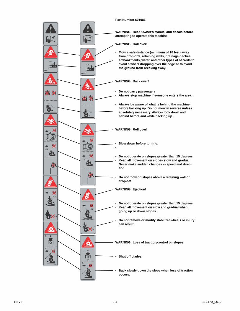
Part Number 601981
WARNING: Read Owner’s Manual and decals before attempting to operate this machine.
WARNING: Roll over!
• Mow a safe distance (minimum of 10 feet) away from drop-offs, retaining walls, drainage ditches, embankments, water, and other types of hazards to avoid a wheel dropping over the edge or to avoid the ground from breaking away.
WARNING: Back over!
• Do not carry passengers• Always stop machine if someone enters the area.
• Always be aware of what is behind the machine before backing up. Do not mow in reverse unless absolutely necessary. Always look down and behind before and while backing up.
WARNING: Roll over!
• Slow down before turning.•
• Do not operate on slopes greater than 15 degrees.• Keep all movement on slopes slow and gradual.
Never make sudden changes in speed and direc-tion.
• Do not mow on slopes above a retaining wall or drop-off.
WARNING: Ejection!
• Do not operate on slopes greater than 15 degrees.• Keep all movement on slow and gradual when
going up or down slopes.
• Do not remove or modify stabilizer wheels or injury can result.
WARNING: Loss of traction/control on slopes!
• Shut off blades.
• Back slowly down the slope when loss of traction occurs.
601981
1.
2.
601981
1.
2.

112479_0612 2-5 REV F
601815B
601815
• Do not overfill battery.• Electrolyte may overflow and
damage paint, wiring or struc-ture. When cleaning the battery, use soap and water. Be careful not to get soap and water into the battery. Use soda mixed in water to clean corrosion off the terminals.
• Always wear eye protection when checking the battery, acid can cause serious injury to skin and eyes. If contact occurs, flush area with clean water and call physician immediately. Acid will also damage clothing.
DANGER: Battery Hazards!
• Avoid skin contact with battery acid.
• Do not allow open flame near the battery when charging.
• Hydrogen gas forms inside the bat-tery. This gas is both toxic and flam-mable and may cause an explosion if exposed to flame. Always remove the negative ground first and replace it last.
Part Number 601815

REV F 2-6 112479_0612
112479_0612 2-7 REV F
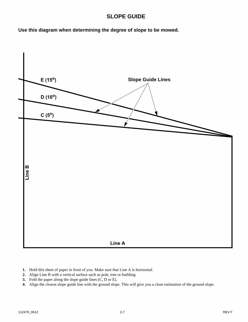
SLOPE GUIDE
Use this diagram when determining the degree of slope to be mowed.
1. Hold this sheet of paper in front of you. Make sure that Line A is horizontal.2. Align Line B with a vertical surface such as pole, tree or building.3. Fold the paper along the slope guide lines (C, D or E).4. Align the closest slope guide line with the ground slope. This will give you a close estimation of the ground slope.
E (15o)
D (10o)
C (5o)
Line
B
Line A
Slope Guide Lines

REV F 2-8 112479_0612
112479_0612 3-1 REV F
OPERATION
Safe Operating PracticesThis product is capable of amputating hands and feet and
throwing objects. Always follow all safety instructions to avoidserious injury or death.
Operation Evaluate the terrain to determine what accessories and
attachments are needed to properly and safely performthe job. Only use accessories and attachments approvedby the manufacturer.
Clean battery compartment, drive motor compartment,mower deck, seat etc. of all dirt and debris. Keep unit freeof grass clippings, leaves and other debris. DO NOTspray with water to clean unit. Do not use, solvents, hardcleaners or abrasives. Use only compressed air. Wearadequate eye and hearing protection when cleaning theunit.
Never leave a running machine unattended. Always stopon level ground, disengage deck clutch, place steeringcontrol levers in park brake position, turn key to off posi-tion and remove key before leaving operator’s seat forany reason including emptying the catcher or uncloggingthe chute.
Always remain seated while operating machine. Always keep safety shields and covers in place. Always maintain a safe distance from people and pets
when mowing. Always stop machine if someone entersthe area.
Avoid injury. With key in ON position, mower blades canengage when deck clutch switch is engaged, even if drivemotors are not turning. Keep area clear of bystanderswhen engaging deck clutch.
Always operate machine in daylight or with adequateworking lights.
Follow daily and weekly checklists, making sure electri-cal connections are secured and bolts are tightened.
Always observe traffic laws while driving machine fromone location to another. Watch for traffic when operatingnear or crossing roadways.
Always be alert for hazards such as rocks, metal objectsand other debris which may be thrown or entangled bymower blades. Watch out for holes or deep depressions.
Inspect area to be mowed for hazards such as rocks,metal objects and other debris which may be thrown orentangled by mower blades. Remove these objects beforemowing.
Always inspect machine for damage after striking a for-eign object. If damage is found, repair machine immedi-ately. Be sure to stop on level ground, disengage deckclutch, place steering control levers in park brake posi-tion, turn key to OFF position and remove key whenleaving operator’s seat to inspect damage.
Always wear adequate ear protection, such as earplugs,when operating this equipment as prolonged exposure touncomfortable or loud noises can cause impairment orloss of hearing. Do not wear radios or music headphones
while operating the machinery. Safe operation requiresyour full attention.
Do not operate the equipment while wearing sandals, ten-nis shoes, sneakers, shorts or any type of loose fittingclothing. Long hair, loose clothing or jewelry may gettangled in moving parts. Always wear long pants, safetyglasses, ear protection and safety shoes when operatingthis machine.
Always wear safety goggles or safety glasses with sideshields when operating the mower.
Always be aware of what is behind the machine beforebacking up. Do not mow in reverse unless absolutely nec-essary. Always look down and behind before and whilebacking up.
Never push forward suddenly on your steering controllevers while the machine is in rearward motion becausemachine may tip backwards.
Never pull back suddenly on your steering control leverswhile the machine is in forward motion.
When moving in reverse, push forward slowly on steer-ing control levers and avoid sudden movement. Rapidmovement of the steering control levers in either direc-tion could result in a reaction of the machine that cancause serious injury.
Never operate a poorly maintained machine. Never attempt high speed maneuvering, especially in
crowded, congested areas or on slopes. Never allow persons to operate this machine without
proper instruction or allow children to operate machine.Allow only responsible adults who have read and under-stand these instructions to operate this machine.
Never put hands or feet under any part of the machinewhile it is running.
Never carry passengers. Never direct discharged material toward anyone. Avoid
discharging material against a wall or obstruction. Mate-rial may ricochet back toward the operator. Always dis-engage the blades and wait for them to stop beforecrossing gravel drives, walks or roads.
Always keep clear of the mower blades and attachmentsduring their operation.
Turn off blades when not mowing. Slow down before turning. Turn the key to the OFF position before removing the
grass catcher or unclogging the discharge chute. Neverclear the discharge chute with the machine running. Turnthe key to the OFF position, disengage deck clutch, placesteering control levers in park brake position and be surethe blades have stopped before cleaning. Use a stick toclear a plugged discharge area. Never use your hand!
Do not operate the machine while under the influence ofalcohol or drugs.
Exercise caution when loading or unloading the machineonto a trailer or truck.
Data indicates that operators, age 60 years and above, areinvolved in a large percentage of riding mower-relatedinjuries. These operators should evaluate their ability to

REV F 3-2 112479_0612
operate the mower safely enough to protect themselvesand others from serious injury.
Follow the manufacturer’s recommendation for wheelweights or counterweights.
If any attachment or additional weight is mounted on therear of the unit, any rapid movement of the steering con-trol levers in either direction could result in a reaction ofthe machine that can cause serious injury.
Clean flammable material from machine. Preventfires by keeping battery compartment, deck and oper-ator’s station clean of accumulated trash, grass clip-pings, and other debris.
Using a ramp Use extreme caution when loading and unloading a unit
onto a truck or trailer with a ramp. Use only a single, full width ramp; do not use individual
ramps for each side of the unit. Having a full width rampprovides a surface for the mower frame to contact if theunit starts to tip backwards. It also reduces the risk of awheel going off and the machine tipping over.
Do not exceed a 15 degree angle between the ramp andthe ground or between the ramp and the trailer or truck.
When on a ramp avoid sudden acceleration
Slope operationSlopes are a major factor in loss-of-control and tip-over
accidents, which can result in severe injury or death. Allslopes require extra caution. If you cannot back up the slopeor if you feel uneasy on it; do not mow it. REMINDER: Onlyoperate on slopes of 15 degrees or less.
Use extreme caution when operating on slopes.• Be extremely careful changing directions on a slope.
Slow down.• Do not operate where the machine could slip or tip.• Turn slowly• Turn on the most level part of the slope• To maximize traction, it is better to turn the front of the
machine uphill, rather than downhill. If drive tires losetraction, steering control is lost which could causeserious injury or death.
• If it becomes necessary to turn downhill, turn slowlyand gradually.
Do not remove or modify the stabilizer wheels. Watch for holes, ruts, bumps, rocks or other hidden
objects. Uneven terrain could overturn the machine. Tallgrass can hide obstacles.
Remove obstacles such as rocks, tree limbs, etc. Keep all movement on slopes slow and gradual. Do not
make sudden changes in speed or direction. Avoid starting and stopping on a slope. If tires lose trac-
tion, disengage the blades and proceed slowly straightdown the slope.
Mow a safe distance (minimum of 10 feet, 3.05 meters)away from drop-offs, retaining walls, drainage ditches,embankments, water, and other types of hazards to avoida wheel dropping over the edge or to avoid the groundfrom breaking away. This will reduce the risk of themachine suddenly rolling over causing serious injury ordeath.
Use a walk behind, push mower or hand-held trimmer onslopes and near drop-offs, retaining walls, drainageditches, embankments and water to avoid machine roll-over and serious injury or death.
Do not mow on wet grass. Reduced traction could causesliding and loss of steering control.
Do not tow on slopes. The weight of the towed equip-ment may cause loss of traction and control.
Do not try to stabilize the machine by putting your footon the ground.
If the mower’s tires lose traction when operating onslopes, disengage the deck clutch, place the steering con-trol levers in the park brake position, turn the key to theOFF position and get help.
Never make sudden starts, stops, turns, or reverse direc-tion, especially when maneuvering on slopes. The steer-ing is designed for sensitive response. Rapid movementof the steering control levers in either direction couldresult in a reaction of the machine that can cause seriousinjury.
Never stop suddenly while backing down slopes. Thisaction may result in a reaction of the machine that cancause serious physical injury.
The Hustler® mower is capable of operating horizontally(traverse) on moderate slopes. When operating on slopesup to 15 degrees, be aware of any conditions that maycause the mower drive tires to lose traction resulting in apossible loss of control of the machine. An operatorshould not operate on a slope until he is thoroughlyfamiliar with the equipment.Do not operate on slopes greater than 15 degrees.Refer to Slope Guide, page 2-7, when determining thedegree of slope to be mowed.It is strongly recommended that the operator drive themachine off of the slope, using extreme caution, if anysign of loss of traction is detected. Wait until the condi-tion that caused the problem is resolved before attempt-ing to operate on the slope again.Terrain conditions can affect traction resulting in possibleloss of control of the machine. Some of the conditions tobe aware of are:1. Wet terrain2. Depressions in the ground; i.e. holes, ruts, washouts3. Mounds of dirt4. Soil type; i.e. sand, loose dirt, gravel, clay5. Grass type, density, and height6. Extremely dry conditions of grass7. Tire pressureThe attachments mounted to the mower will also affectthe way it handles on a slope. Be aware that each attach-ment’s characteristics vary.Another consideration is to always mow a safe distance(minimum of 10 feet 3.05 meters) away from drop-offs,retaining walls, drainage ditches, embankments, water,and other types of hazards to avoid a wheel droppingover the edge or to avoid the ground from breaking awayand always be aware of what is located at the bottom ofthe slope. This will reduce the risk of the machine sud-denly rolling over causing serious injury or death.

112479_0612 3-3 REV F
Extreme caution should be used when there is a hazardlocated at the bottom of the slope. Some examples are:1. Water; i.e. lake, river2. Cliffs, retaining walls3. Roads, highways4. Buildings5. RocksThese are just a few examples of situations when cautionmust be used when operating on a slope. There are manyother possibilities too numerous to mention. Just remem-ber to always exercise extreme caution when operatingon any slope.
The ROPS may minimize chance of injury or death fromrollover. Seat belt must be fastened while operating amower equipped with ROPS in the raised and securedposition. Both retaining pins and hair pins must beinstalled. Failure to use seat belt with ROPS will result inserious injury in the event of a roll over.
ChildrenTragic accidents can occur if the operator is not alert to
the presence of children. Children are often attracted to themachine and the mowing activity. Never assume thatchildren will remain where you last saw them.
Never leave machine unattended with key in switch,especially with children present.
Children or bystanders may be injured if they move orattempt to operate the machine while it is unattended.Always disengage deck clutch, place steering controllevers in park brake position, turn key to OFF positionand remove key when leaving operator’s seat.
Keep children out of the mowing area and under thewatchful care of a responsible adult other than the opera-tor.
Be alert and turn the machine off if children enter thearea.
Before and while backing, look behind and down forsmall children.
Never carry children, even with the blades off. They mayfall off and be seriously injured or interfere with safemachine operation. Children who have been given ridesin the past may suddenly appear in the mowing area foranother ride and be run over or backed over by themachine.
Never allow children to operate the machine. Use care when approaching blind corners, shrubs, trees,
the end of a fence or other objects that may obscurevision.
Never allow children or others in or on towed equipment.
Control PanelA. Deck clutch switch (Fig. 3-1) — this switch engages the
deck motors. Pull the switch up to engage and pushswitch down to disengage the motors.IMPORTANT: Never engage deck motors when the deckis under load. Motors or deck could be damaged.
B. Ignition switch (Fig. 3-1) — a two position switch: OFFand ON. With key inserted, rotate it clockwise to the ONposition; release key.
When shows on the Digital Display thetraction drive system is activated and ready to operate.
C. Digital display (Fig. 3-1) — This display showsimportant electrical system information. Refer to theElectrical section for complete information.
ControlsA. Steering control levers (Fig. 3-2 & Fig. 3-3) — these
levers control the mower’s speed, direction, stopping,neutral lock, and park brake. Levers are used to steer,accelerate, decelerate, stop and change direction. Whenthe control levers are in the park brake position (Fig. 3-3)the mower will not move when the drive system isoperating
WARNING: The parking brake may not hold themachine if parked on a slope. Block or chock themachine when parked on a slope
B. Deck lift pedal (Fig. 3-4) — the deck lift pedal is used toraise or lower the deck. Push on the pedal to raise thedeck and then place the deck height locking pin into thedesired cutting height hole.
Push the deck lift pedal to raise the deck when going overobstructions.
Safety start interlock systemThe machine is equipped with a safety start interlock system
consisting of the park brake switches, seat switch, and deckclutch switch.
Check mower safety start interlock system daily, prior tooperation. This system is an important mower safety feature. Itshould be repaired immediately if it malfunctions. The machineincorporates a separate seat switch which will stop the drivesystem and deck motors when the operator is unseated for any
A. Deck clutch switchB. Ignition switch
C. Digital display
Fig. 3-1
A
C
B

REV F 3-4 112479_0612
reason while the mower is operating. This is a safety featuredesigned to prevent runaway or accidental entanglement. Toinspect the system:
1. The operator must be on the seat when testing the seat
switch.2. Set both steering control levers in the park brake position.3. Start the traction drive system.4. With the deck clutch switch up and/or the steering control
levers in neutral, slowly raise off of the seat. Thefollowing code should appear on the Digital Display:
The traction drive system is disabled and the parkbrake will engage. The deck drive system should stop.
5. If the deck drive system fails to stop when the deckclutch switch is up or one or both of the steering controllevers are in neutral and the operator is off the seat, checkthe function of the seat switch. If the seat switch is notoperating properly (is not opening or closing) and if the
cause can not be determined, contact your Hustler®
Dealer.
WARNING: The safety interlock system shouldalways function per steps 4 and 5. If it does not func-tion properly, it should be corrected immediately. Donot operate machine without properly functioning seatsafety switch.
Traction drive system startingThe mower’s safety start interlock system is also designed to
protect the operator and others from accidental injury due tounintentional traction drive system starting. The traction drivesystem will not engage until:
A. Steering control levers are in the park brake position.B. Deck clutch switch is in the down (OFF) position.
WARNING: The safety interlock system must not bedisconnected or bypassed. Doing so could cause themachine to operate unexpectedly resulting in personalinjury.
NOTE: The operator’s seat is equipped with a separatesafety switch. If for any reason the operator should becomeunseated when the steering control levers are not in the parkbrake position (park brake switches are disengaged) or the deckclutch switch is engaged the traction drive system will stop.
The following steps are the correct procedures for starting thetraction drive system. If difficulty is encountered, contact theHustler® Dealer in your area.
1. Before starting the mower each day, perform daily pre-operation checking. (See “Safety start interlock system”on page 3-3.)
2. Make sure the steering control levers are in the parkbrake position and deck clutch switch is disengaged.Only start the traction drive system from the operator’sposition.
3. Insert key in switch and rotate clockwise to ON positionto activate starting sequence. Release key and wait forstarting sequence to end (indicated by the followingmessage shown on the digital display).
Fig. 3-2
Fig. 3-3
Fig. 3-4
Shown with steering control levers in neutral position
Steering control lever
Shown with steering control levers in park brake position
Deck lift pedal

112479_0612 3-5 REV F
4. Perform test to make sure safety start interlock system isoperating properly. (See “Safety start interlock system”on page 3-3.).
5. When stopping the traction drive system, place thesteering control levers in the park brake position,disengage the deck clutch, and rotate key counter-clockwise to the OFF position. Remove the key fromswitch before leaving the machine.
Stopping the traction drive systemUse the following procedure to shut off the traction drive
system after operating the equipment.1. Place the steering control levers in the park brake
position.2. Disengage the deck clutch.3. Rotate key counter-clockwise to the OFF position.
Remove the key from switch before leaving themachine.
Moving mower with non-functioning traction drive system
WARNING: Always disconnect batteries when trans-porting unit.
If it becomes necessary to move the machine when thetraction drive system is inoperative, contact local Hustler®
dealer. Do not tow the machine. Move it by hand or use a winch to
load on a trailer for transporting.When transporting on another vehicle, the mower must be
secured.
ROPS
(Roll Over Protective Structure)A ROPS may minimize the chance of injury or death from
rollover. The two-post ROPS can be pivoted down by removing the
right and left retaining rings (Fig. 3-5) and pulling out on theclevis pins so that the machine can operate under low hangingtree limbs or other obstructions. Do not wear the seat belt whenthe ROPS is in the lowered position. Use the ROPS in the“folded” position only when it is absolutely necessary.
WARNING: Do not operate the mower with theROPS folded (lowered position) as a standard operat-ing mode. A folded ROPS does not provide rolloverprotection.
WARNING: Always wear your seat belt unless theROPS is folded down. In this case, the seat belt shouldnever be worn.
WARNING: To minimize chance of injury or deathfrom rollover: Keep ROPS in the raised and locked position anduse the seat belt.Never operate machine on a slope with the ROPSfolded down (lowered position).There is no roll over protection when the ROPS isin the lowered position.Lower the ROPS only when absolutely necessary.Drive slowly and carefully. Raise the ROPS as soonas clearance permits. Read and follow slope opera-tion instructions and warnings.Do not wear seat belt when the ROPS is in the low-ered position.
WARNING: Always pull from the tractor hitch. Donot attach chains or ropes to the ROPS for pulling pur-poses, as the machine can tip backwards.
Always fasten seat belt during operation of the machine(mower equipped with ROPS in “raised/up” position).
Inspect the area to be mowed for proper overhead clearance(tree limbs, guy wires, doorways, etc)
Do not contact any overhead object with the ROPS.
Seat belt maintenanceInspect the seat belt system (all seat, seat belt parts, seat pan
and seat pan latch) daily prior to mowing for signs of any
Fig. 3-5
Retaining ring
ROPS
Clevis pin

REV F 3-6 112479_0612
damage. These parts should be replaced if any parts indicatesigns of:
A. cutsB. frayingC. extreme or unusual wearD. significant discoloration due to UV exposureE. dirt or stiffnessF. abrasion to the seat belt webbingG. damage to the buckle, latch plate or hardware.H. or any other problemIf the seat belt is to be cleaned, use soap and water. Do not use
carbon tetrachloride, naphtha, etc., as these will weaken thewebbing. For the same reason, do not bleach or dye thewebbing. Replace seat belt if worn or damaged.
Possible damage to the ROPSIf the unit has rolled over or the ROPS has been in some other
type of accident (such as hitting an overhead object duringtransport), the ROPS must be replaced to retain the bestprotection.
Following an accident, check the ROPS, the operator’s seat,the seat belt, seat belt mountings and seat latch for possibledamage. Before operating the machine, replace all damagedparts.
IMPORTANT: Do not attempt to weld or straighten theROPS.
WARNING: The ROPS structure’s protectivecapability may be impaired by structural damage,overturn or alteration. Do not remove or alter any ofthe ROPS parts. Do not attempt to weld or straightenROPS. Failure to adhere to these instructions couldresult in severe injury or death.
ROPS InspectionNOTE: Inspect the ROPS after the first 20 hours of opera-
tion. Following the initial inspection, check the ROPS afterevery 500 hours of operation or every six months, whichevercomes first.
1. Check the torque of the ROPS mounting bolts. Tightenthe bolts to the correct torques as shown below ifnecessary. Fig. 3-6
2. Inspect the operator’s seat and the mounting parts for theseat belt. Tighten the bolts to the correct torque as shownbelow if necessary and replace parts that show wear ordamage.
3. Inspect the seat latch to make sure it is secured andfunctioning properly. Adjust or repair as necessary.
WARNING: Make sure seat pan is securely bolteddown prior to each use to prevent seat from moving/tilting in the event of mower tipping or rollover
Torque values are given below:Ft-lbs. Nm
Hustler® Zeon ROPS mounting bolts . . . 85 . . . . 115Seat belt mounting hardware. . . . . . . . . . 48 . . . . 65
Driving the mower
DANGER: Never make sudden stops or reversedirection, especially when maneuvering on a slope.The steering is designed for sensitive response. Rapidmovement of the steering control levers in eitherdirection could result in a reaction of the machine thatcan cause serious injury.
WARNING: Make sure seat pan is securely bolteddown prior to each use to prevent seat from moving/tilting in the event of mower tipping or rollover.
After starting the traction drive system, engage the steeringcontrol levers and steer as follows:
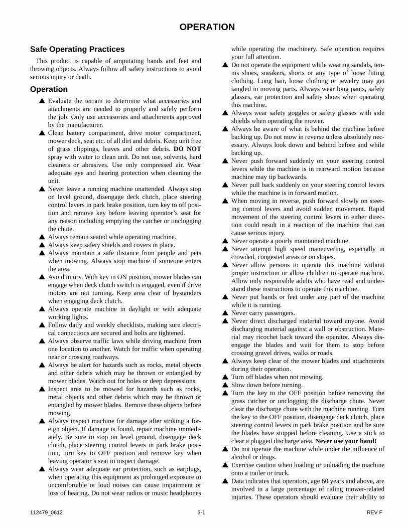
To go forward, push steering control levers forward an equaldistance (Fig. 3-7).
To go in reverse, pull steering control levers rearward anequal distance (Fig. 3-7).
To turn left, move the right steering control lever fartherforward from neutral than the left steering control lever.(Fig. 3-7)
To turn right, move the left steering control lever fartherforward from neutral than the right steering control lever.(Fig. 3-7)
Zero radius turn, move one steering control lever forwardand the other steering control lever back of neutral. This willallow the drive wheels to counter-rotate. (Fig. 3-7)
To stop or decrease speed, move steering control levers toneutral. When going forward pull back gently on steeringcontrol levers. When going in reverse push forward gently onsteering control levers..
For an emergency stop, there are two methods that can beused in an emergency situation.
Fig. 3-6
ROPS mounting
bolts
ROPS mounting
nutsTorque to 85 ft.-lbs. (115 Nm)
ROPS Post
Tractor frame
112479_0612 3-7 REV F
1. When traveling forward or rearward, place the steeringcontrol levers in the park brake position immediately.When moving in the rearward direction push forwardgently on steering control levers and avoid suddenmovement. Any sudden movement could cause the frontof the mower to come off of the ground resulting inpossible loss of control causing serious injury or death.
2. Turn the ignition key to the OFF position. This will shutdown the traction drive system and the deck drivesystem.
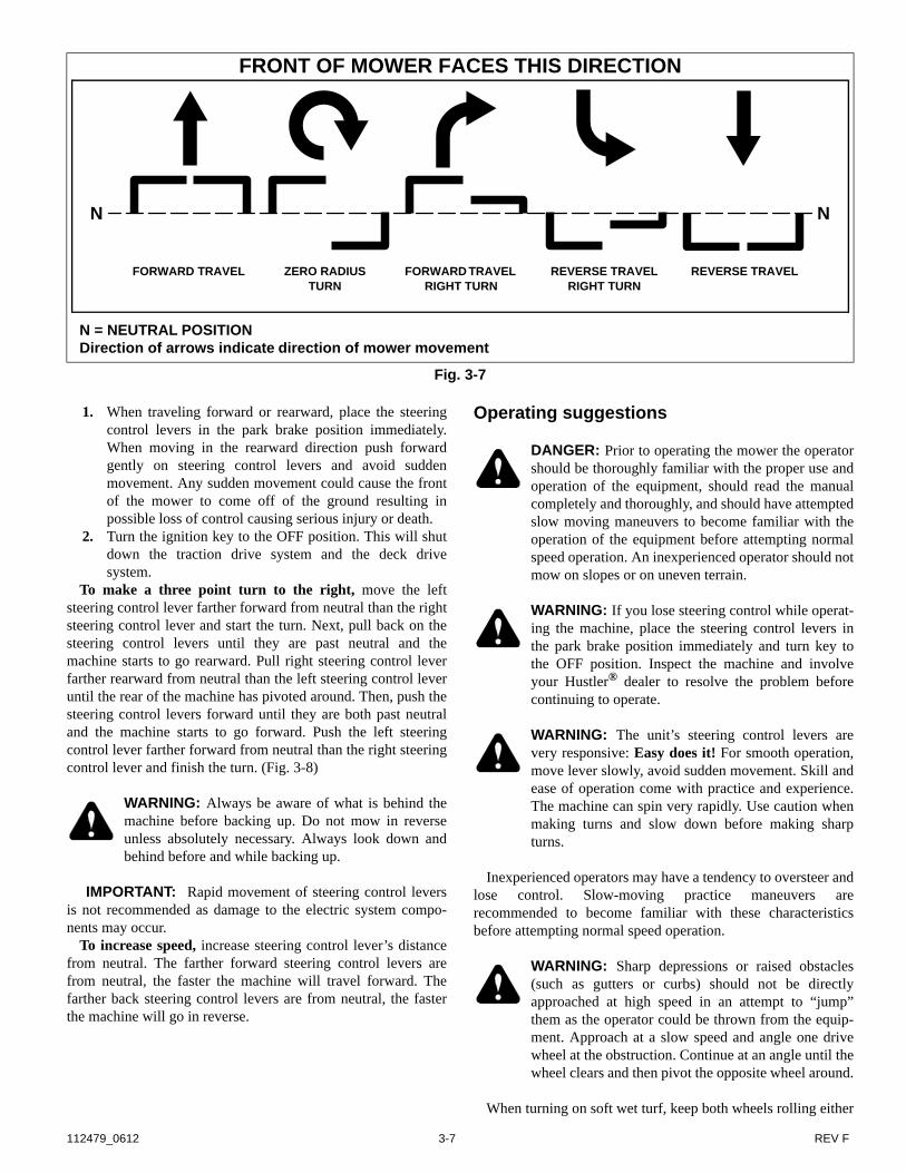
To make a three point turn to the right, move the leftsteering control lever farther forward from neutral than the rightsteering control lever and start the turn. Next, pull back on thesteering control levers until they are past neutral and themachine starts to go rearward. Pull right steering control leverfarther rearward from neutral than the left steering control leveruntil the rear of the machine has pivoted around. Then, push thesteering control levers forward until they are both past neutraland the machine starts to go forward. Push the left steeringcontrol lever farther forward from neutral than the right steeringcontrol lever and finish the turn. (Fig. 3-8)
WARNING: Always be aware of what is behind themachine before backing up. Do not mow in reverseunless absolutely necessary. Always look down andbehind before and while backing up.
IMPORTANT: Rapid movement of steering control leversis not recommended as damage to the electric system compo-nents may occur.
To increase speed, increase steering control lever’s distancefrom neutral. The farther forward steering control levers arefrom neutral, the faster the machine will travel forward. Thefarther back steering control levers are from neutral, the fasterthe machine will go in reverse.
Operating suggestions
DANGER: Prior to operating the mower the operatorshould be thoroughly familiar with the proper use andoperation of the equipment, should read the manualcompletely and thoroughly, and should have attemptedslow moving maneuvers to become familiar with theoperation of the equipment before attempting normalspeed operation. An inexperienced operator should notmow on slopes or on uneven terrain.
WARNING: If you lose steering control while operat-ing the machine, place the steering control levers inthe park brake position immediately and turn key tothe OFF position. Inspect the machine and involveyour Hustler® dealer to resolve the problem beforecontinuing to operate.
WARNING: The unit’s steering control levers arevery responsive: Easy does it! For smooth operation,move lever slowly, avoid sudden movement. Skill andease of operation come with practice and experience.The machine can spin very rapidly. Use caution whenmaking turns and slow down before making sharpturns.
Inexperienced operators may have a tendency to oversteer andlose control. Slow-moving practice maneuvers arerecommended to become familiar with these characteristicsbefore attempting normal speed operation.
WARNING: Sharp depressions or raised obstacles(such as gutters or curbs) should not be directlyapproached at high speed in an attempt to “jump”them as the operator could be thrown from the equip-ment. Approach at a slow speed and angle one drivewheel at the obstruction. Continue at an angle until thewheel clears and then pivot the opposite wheel around.
When turning on soft wet turf, keep both wheels rolling either
FRONT OF MOWER FACES THIS DIRECTION
Fig. 3-7
NN
FORWARD TRAVEL ZERO RADIUS TURN
FORWARD TRAVEL RIGHT TURN
REVERSE TRAVEL RIGHT TURN
REVERSE TRAVEL
N = NEUTRAL POSITIONDirection of arrows indicate direction of mower movement

REV F 3-8 112479_0612
forward or backward. Pivoting on one stopped wheel candamage turf. This is especially important when mowing.
Keep blades sharp. Many professional mowing companieshave additional sets of blades and change blades twice a day:once in the morning and again at noon. Many problems withincorrect cutting patterns are due to dull blades or bladeswhich have been sharpened incorrectly. Information onsharpening blades is listed in this manual’s maintenance section.In addition, most communities have individuals or companieswhich specialize in sharpening mower blades. Blade sharpnessshould be checked daily.
DANGER: Never work with blades while key is inthe ignition switch. Always place deck clutch switchin the disengaged position, place steering controllevers in the park brake position and turn key to theOFF position and remove key from switch. Block upmower when you must work under it. Wear gloveswhen handling blades. Always check for blade dam-age if mower strikes a rock, a branch or another for-eign object during mowing!
Direct grass discharge to right, away from unmown area.Select a mowing pattern that directs grass discharge towards theoutside, not towards center, of mowing area. Generally, thismeans using a pattern utilizing left turns because side dischargeis to right. In any case, avoid throwing grass discharge ontounmowed area because grass is then mowed “twice”. Mowingtwice puts an unnecessary load on the unit and reduces mowingefficiency.
When mowing a lawn for the first time cut grass slightlylonger than normal to avoid scalping uneven terrain. Whenpossible, it is best to use the cutting height that was used in thepast. When cutting grass taller than six inches, you may want tomow the lawn twice to achieve a better quality of cut.
During normal mowing cut only about 1/3 of the grassblade. Cutting more than that is not recommended unless grassis sparse or it is the end of the mowing season.
Alternate mowing direction to keep the grass growingstraight and better dispersion of the clippings.
Remember, grass grows at different rates at different timeof the year. Mow more often in the early spring to maintain thesame cutting height. As the growth rate slows in mid summer,mow less frequently. If you cannot mow at a regular interval,mow at a high cutting height; then mow again two days later at alower cutting height.
Raise the cutting height of the mower if the cutting width ofthe mower is wider than the previous mower. This ensures thatuneven turf is not cut too short.
Raise the cutting height of the mower if the grass if slightlytaller than normal or if it contains a high degree of moisture.Then mow it again with the cutting height set lower.
If the machine’s forward motion must be stopped whilemowing, a clump of grass clippings may drop onto your lawn.To avoid this, move onto a previously cut area with the bladesengaged.
Fig. 3-8
Step 1
Three point turn
Step 2
Step 3
Right
control
lever
Left
control
lever
Neutral
Right
control lever
Left control lever
Neutral
Neutral
Left control leverRight control lever

112479_0612 3-9 REV F
WARNING: Never direct discharge of material frommower deck towards bystanders. Do not operate themower without either the discharge chute or the entiregrass collection system in place. Fig. 3-9
Mower deck operation
DANGER: Never attempt to make any adjustments tothe mower deck while the traction drive system is onor with the deck clutch engaged. Mower blades cannotbe seen and are located very close to deck housing.Fingers and toes can be cut off instantly.
With the traction drive system on, raise the blades so that theyare out of the grass and engage the deck clutch switch (Fig. 3-2).
Deck cutting height adjustmentDeck height is adjustable from 1”- 3-1/2” (3.81 cm - 8.89 cm)
in 1/4” (.64 cm) increments. The deck can also be adjusted to a4” or 4/12” (10.16 cm or 11.43 cm) cutting height.
Step on the deck lift pedal and latch the transport lever in thedeck transport position. Pull the adjusting pin out of the holethat it is in and insert it into the desired cutting height hole. Stepon the deck lift pedal to release the transport lever. Fig. 3-10
Step on the deck lift pedal and raise the deck to its highestposition and latch the transport lever in place when transportingthe unit. Fig. 3-10.
Anti-scalp wheelsAnti-scalp wheel kits are standard on Hustler® Zeon units.
These anti-scalp wheels are designed to minimize scalpingwhen mowing on rough uneven terrain.
After setting the cutting height, adjust the anti-scalp wheels sothey extend below the deck but do not contact the ground.They should always be at least 1/4” to 3/4” (6.35mm to19.05mm) below the deck. With the unit sitting on a flat levelsurface, the wheel position can be adjusted up or down asneeded from 3/4” to 1-3/4” (19.05mm to 44.45mm) below theblade surface. Move the wheels up or down, in 1/2” (12.70mm)increments, using the different axle mount holes in the wheelmount bracket. Fig. 3-11
Fig. 3-9
Side discharge chute
Fig. 3-10
Fig. 3-11
Transport lever
Pin
Cutting height holes
Anti-scalp wheel

REV F 3-10 112479_0612

112479_0612 4-1 REV F
MAINTENANCE & ADJUSTMENTS
Safe Servicing PracticesThis product is capable of amputating hands and feet and
throwing objects. Always follow all safety instructions to avoidserious injury or death.
Service Unless specifically required, DO NOT have traction
drive system running when servicing or making adjust-ments to the machine. Park the machine on level ground.Place steering control levers in the park brake position,disengage deck clutch, lower deck, rotate key to OFFposition and remove key from switch before doing anymaintenance. Wait for all movement to stop beforeadjusting, cleaning or repairing. Repairs or maintenancerequiring power should be performed by trained mainte-nance personnel only. Read and observe safety warningsin front of manual.
Remove key, disconnect batteries and read owner’s man-ual before adjusting or repairing unit.
Before working on or under the deck, make certain trac-tion drive and deck drive systems cannot be accidentallystarted. Turn key to OFF position, remove key fromswitch and disconnect the negative (black) battery cablefrom batteries for maximum safety. Repairs or mainte-nance requiring power should be performed by trainedmaintenance personnel only.
Use a stick or similar instrument to clean under themower making sure that no part of the body, especiallyarms and hands are under mower.
Keep your machine clean and remove any deposits oftrash and clippings, which can cause fires and overheat-ing. Allow machine to cool before storing.
Clean flammable material from machine. Preventfires by keeping battery compartment, deck and oper-ator’s station clean of accumulated trash, grass clip-pings, and other debris.
Clean battery compartment, drive motor compartment,mower deck, seat etc. of all dirt and debris. Do not sprayunit with water. Do not use, solvents, hard cleaners orabrasives. Use only compressed air.
Always wear adequate eye protection when servicing thebatteries, or when grinding mower blades and removingaccumulated debris.
Never attempt to make any adjustments or repairs to themower’s drive system, mower deck or any attachmentwhile the traction drive system is running or deck clutchis engaged. Repairs or maintenance requiring powershould be performed by trained maintenance personnelonly.
Never work under the machine or attachment unless it issafely supported with jack stands. Make certain machineis secure when it is raised and placed on the jack stands.The jack stands should not allow the machine to movewhen the traction drive system is running and the drivewheels are rotating. Use only certified jack stands. Useonly appropriate jack stands, with a minimum weight rat-
ing of 2000 pounds (907.2 kg) to block the unit up. Usein pairs only. Follow the instructions supplied with thevehicle stands.
Do not touch hot parts of machine. Keep nuts and bolts tight, especially the blade attachment
bolts. Keep equipment in good working condition. Never tamper with safety devices. Check their proper
operation regularly. Turn the key to the OFF position before removing the
grass catcher or unclogging the discharge chute. Neverclear the discharge chute with the machine running. Turnthe key to the OFF position and be sure the blades havestopped before cleaning. Use a stick to clear a pluggeddischarge area. Never use your hand!
Stop unit, and allow blades to stop before uncloggingchute.
Grass collection system components are subject to wear,damage and deterioration, which could expose movingparts or allow objects to be thrown. Frequently checkcomponents and replace with manufacturer’s recom-mended parts, when necessary.
Exercise caution when working under the deck as themower blades are extremely sharp. Wear gloves and useextra caution when servicing them.
Use only genuine Hustler® replacement parts to ensurethat original standards are maintained
Always remove key and disconnect negative (black) bat-tery cable from batteries before working on this unit.
Always disconnect batteries when transporting unit. Keep unit free of grass clippings, leaves and other debris.
DO NOT spray with water to clean unit. Use only com-pressed air. Wear adequate eye and hearing protectionwhen cleaning the unit.
Always wear safety glasses and protective gear near bat-tery. Use insulated tools.
IntroductionRegular maintenance is the best prevention for costly
downtime or expensive, premature repair. The following pagescontain suggested maintenance information and scheduleswhich the operator should follow on a routine basis. For moredetailed information order the correct parts manual for yourunit. Refer to the Product Literature section of this manual.
Remain alert for unusual noises, they could be signaling aproblem. Visually inspect the machine for any abnormal wear ordamage. A good time to detect potential problems is whileperforming scheduled maintenance service. Correcting theproblem as quickly as possible is the best insurance.
Daily inspect mower for grass clippings and wire and stringtangles. The underside of the mower deck may collect a build-up of grass clippings and dirt, especially when grass is wet orhas high moisture content. This build-up will harden, restrictingblade and air movement and will probably show a poorer qualityof cutting. Therefore it should be removed routinely.
To do this it will be necessary to raise and block the deck,using jack stands or blocks, in the full up position and scrape thebuild-up from underneath.

REV F 4-2 112479_0612
Some repairs require the assistance of a trained servicemechanic and should not be attempted by unskilled personnel.Consult your Hustler® service center when assistance is needed.
Torque values
WARNING: Particular attention must be given totightening the drive wheel lug nuts and blade spindlebolts. Failure to correctly torque these items mayresult in the loss of a wheel or blade, which can causeserious damage or personal injury.
Torque values are given below:
Lug nuts only - It is recommended that these be checked afterthe first 2 hours of operation, initially, every 100 hours andfollowing removal for repair or replacement.
For all other torques refer to the various mower parts manualsfor standard torque chart. See the Product Literature section ofthis manual for ordering information.
TiresIt is important for level mowing that the tires have the same
amount of air pressure. The recommended pressure are:
Only pneumatic tires are approved for use on Hustler® TurfConsumer Equipment. Warranty claims will be denied on anymower equipped with non-pneumatic tires.
LubricationUse SAE multi-purpose grease.
Electrical systemThis mower operates on a 48 volt electrical system.Refer to the Electrical section of this manual for detailed
information.
Seat adjustmentThe seat can be adjusted forward and rearward by removing
the lock nut from the seat latch bolt and pivoting the seatplatform up and forward. Then loosen the four cap screws on theunderneath side of the operator’s platform. Position the seatwhere you have the best control of the machine and are the mostcomfortable and then tighten the cap screws. Fig. 4-1
WARNING: Make sure seat pan is securely bolteddown prior to each use to prevent seat from moving/tilting in the event of mower tipping or rollover.
Steering control lever adjustmentThe steering control levers can be adjusted for operator
comfort. By loosening the cap screws that attaches the uppercontrol lever to the lower lever (Fig. 4-2), the upper controllever can be pivoted to fit the operator’s personal preference.
The steering control levers should be adjusted so that they
align with each other when in the neutral position.
Mower blade maintenanceCheck the mower blades daily, they are the key to power
efficiency and well groomed turf. Keep them sharp, a dull bladewill tear rather than cut the grass, leaving a brown ragged top onthe grass within a few hours. A dull blade also requires morepower.
Replace any blade which is bent, cracked or broken.
WARNING: Never attempt to straighten a bent bladeby heating, or weld a cracked or broken blade as theblade may break and cause serious injury. Replaceworn or damaged blades.
DANGER: Never work with blades while key is inthe ignition switch. Always place deck clutch switchin the disengaged position, place steering controllevers in the park brake position, turn key to OFF posi-tion, remove key from switch and disconnect the nega-tive (black) battery cable from the batteries. Block upmower when you must work under it. Wear gloveswhen handling blades. Always check for blade dam-age if mower strikes a rock, branch or other foreignobjects during mowing!
WARNING: Always wear adequate eye protectionwhen grinding mower blades.
Ft-lbs. NmWheel (lug) nuts............................. 65-75.......88.14-101.7Blade spindle bolt bottom .................50 ...............67.8
Drive wheels ......................8-12 psi (55-83 KPa)Gauge wheels .....................8-12 psi (55-83 KPa)
Fig. 4-1
Cap screw

112479_0612 4-3 REV F
Always place deck clutch switch in the disengaged position,place steering control levers in the park brake position and turnkey to OFF position and remove key from switch. Block upmower when you must work under it. Wear gloves whenhandling blades. Always check for blade damage if mowerstrikes a rock, branch or other foreign objects during mowing!
Mower blade removalUse a 3/4” wrench or socket to remove the 1/2” cap screw
holding the blade to the motor shaft from underneath. It may benecessary to use a 1-1/4” wrench to keep the blade adapter fromturning while removing blade cap screw. Fig. 4-6
NOTE: The blade adapter will come off when the blade capscrew is removed.
Sharpen the blades on a grinder following pattern as shown(Fig. 4-3). Touch-up sharpening can be done with a file.
Check the blades for balance following grinding. Acommercial balancing tool is available through most hardwaresupply stores, or balancing can be done by placing the blade onan inverted line punch or 1/2” bolt. Blade should not lean or tilt.Spin the blade slowly, blade should not wobble. If blade is outof balance, true it up before reinstalling.
Lay the blade on a flat surface and check for distortion(Fig. 4-4 and Fig. 4-5). Replace any distorted blade.
Mower blade installationDo not re-use spindle bolts which have stripped, worn or
undercut threads.
Make sure that the blade adapter is seated properly on theblade motor shaft before tightening the blade cap screw. Use a 3/4” socket with a torque wrench to re-attach the blade to themotor shaft from underneath. It will be necessary to use a 1-1/4”wrench to keep the blade adapter from turning. Torque capscrews on motor shafts to 50 foot-pounds (67.8 Nm) whenreinstalling blades. Fig. 4-6
IMPORTANT: The blade sail (curved part) must be point-ing upward toward the inside of the deck to ensure proper cut-ting.
IMPORTANT: When mounting blades, rotate them afterinstallation to ensure blade tips do not touch each other or sidesof the mower.
WARNING: Failure to correctly torque the bolt mayresult in the loss of the blade which can cause seriousinjury.
WARNING: Mower blades are sharp and can cut.Wear gloves and use extra caution when servicingthem.
Fig. 4-2
Upper control lever
Lower control lever
Cap screw
Fig. 4-3
Fig. 4-4
Resharpening pattern
Do not sharpen to original pattern (below). It is easier to get a straight cutting edge following
the resharpening pattern shown above.
Original edge
Warped Blade (Replace)
Straight Blade
Cutting plane
Comparison of Warped and Straight Blades
REV F 4-4 112479_0612
Fig. 4-5
Fig. 4-6
Cutting edge
Twisted Blade Edge (replace)
Cutting edgeCutting Plane
Straight Blade Edge
End view of blades, comparing twisted and straightened blades
Blade adapter
1-1/4” wrench
Blade
3/4” socket

112479_0612 4-5 REV F
NOTES:1. Torque initially and after first 2 hours of operation.2. Refer to Electrical section of this manual for more detailed information.3. Inspect ROPS after the first 20 hours of operation and then after every 100 hours of operation or yearly whichever comes first.
NOTE: After completing maintenance cycle (100 hours), repeat cycle.
Hustler® Zeon
Maintenance Schedule
Refer to Fig. 4-7
SERVICE ATINTERVALS INDICATED
MONTHLYOR 40 HOURS
ANNUALLYOR 100HOURS
Verify safety start interlock system Prior to each use
Visually inspect unit for loose hardware and/or damaged parts Prior to each use
Visually inspect tires Prior to each use
Blades - sharpen & securely fastened Prior to each use
Discharge chute - securely in place & in lowest position Prior to each use
Charge batteries After each use
Clean machine Daily
Grease gauge wheel bearings X
Check battery connections X
Check tire pressure with a gauge X
Grease deck height pivots X
Grease deck lift pedal pivot X
Tighten lug nuts on wheels (1) X
Check ROPS mounting hardware (3) X
Check battery water level (2) Every 30 charging cycles

REV F 4-6 112479_0612
Fig. 4-7
Top View
5
2
4
1
3
22
3
4
5
Hustler® ZeonMaintenance Locator Chart
1. Batteries2. Deck Lift Pivot Zerks (4)3. Drive Tire 4. Front Gauge Wheel Tires5. Front Gauge Wheel Zerks (2)

112479_0612 5-1 REV F
ELECTRICAL SYSTEM
Electrical System Safety Remove key, disconnect the negative (black) battery
cable from batteries and read owner’s manual beforeadjusting or repairing unit.
Always remove key and disconnect the negative (black)battery cable from batteries before working on this unit.
Always disconnect the negative (black) battery cablefrom batteries when transporting unit.
Keep unit free of grass clippings, leaves and other debris.DO NOT spray water to clean unit. Use only compressedair. Wear adequate eye and hearing protection whencleaning the unit.
Always wear safety glasses and protective gear near bat-tery. Use insulated tools.
Clean battery compartment, drive motor compartment,mower deck, seat etc. of all dirt and debris. Do not sprayunit with water. Do not use, solvents, hard cleaners orabrasives. Use only compressed air.
Avoid injury. With key in ON position mower blade canengage when deck clutch switch is engaged, even if drivemotor is not turning. Keep area clear of bystanders whenengaging clutch switch.
All maintenance and storage areas should be properlyventilated in accordance with applicable fire codes andordinances to avoid fire hazards. Proper ventilation isrequired to remove hydrogen gas from the area dur-ing battery charging.The amount of hydrogen gas emitted depends on severalfactors such as; battery charger output rate, battery chargetime and battery condition. Because of the highly volatilenature of hydrogen gas and its propensity to rise andaccumulate at the ceiling in pockets, a minimum of 5 airchanges per hour is recommended. Consult applicablefire and safety codes for the specific ventilation levelsrequirement, as well as requirements for the use of explo-sion proof electrical apparatus.
Never allow flames, sparks or smoking near batteries. Keep batteries out of reach of children. Always keep protective shields, covers and guards in
place and securely fastened. If they become damaged,repair or replace immediately. Never modify or removesafety devices.
Electrical System InformationThe Hustler® Zeon mower is powered by a 48 volt electrical
system. It consists of the following components:1. Traction controller (2)2. Deck controller (1)3. Deck Motor (2)4. Contactor (1)5. Accelerator - right (1)6. Accelerator - left (1)7. Digital display (1)8. Integrated electric transaxle (2)9. 12 volt rechargeable battery (4)
Component MaintenanceIMPORTANT: Maintenance for the various electrical
components found on the Hustler® Zeon should only be per-formed by a Hustler® Zeon trained technican.
Digital DisplayThe function of the digital display, located on the control
panel, is to provide electrical system information to the operator.It gives detailed information in the form of operating codes andsystem troubleshooting codes. It also provides battery chargestatus by way of a LED battery level indicator.
Battery Charge Level Indicator
When the key is in the ON position the charge indicator LEDwill light, indicating the relative charge remaining in thebatteries. When the batteries are fully charged LED 10 or 9 willbe lit. Fig. 5-1
During operation the lit LED will change, moving down theindicator scale as the batteries discharge.
When battery charge is nearly depleted LED 1 and 2 will flashalternately.
NOTE: The battery level indicator will reset once the batter-ies have been fully charged.
IMPORTANT: When battery voltage becomes low, themower blades will stop, although the drive motors will continueto run. When the batteries discharge to this point they requirerecharging. The unit should immediately be returned to thebattery charging area and the unit connected to the batterycharger. The traction drive will continue to operate for a short
A. CodeB. Battery charge level
C. Indicator lightD. Service indicator symbol
Fig. 5-1
D
A
C
B

REV F 5-2 112479_0612
time after the deck shuts down. As system power continues todrop, unit will reduce to half speed and then shut down.
WARNING: Do not attempt to cross roads or rail-ways with low battery levels.
Service Indicator Light / Service Indicator Symbol
The service indicator light will begin to blink when an errorcode has been detected. Fig. 5-1
The service indicator symbol will be displayed when themachine requires servicing. Fig. 5-1
Codes
The digital display provides the codes that are generated bythe different components of the system. Fig. 5-1
There are two types of codes:
1. Startup codesThe startup codes are shown when the key switch isactivated to begin the machine startup sequence.
2. Troubleshooting codesThe troubleshooting codes are shown on the digitaldisplay when a problem is detected within the electricaloperating system.Some of these codes can be readily resolved by theoperator and the rest will require service from yourHustler Dealer.
The following table shows both Startup and TroubleshootingCodes. The Troubleshooting Codes shown are the only ones thatcan be resolved by the operator.
Digital Display Codes
DIGITAL DASH DISPLAY CODE
DESCRIPTION
(READY) Key is in the ON position and the mower is ready to operate
(CUT) Mower deck is operating
Right sideSymptom: Reduced drive speed or no driveCause: High temperature in traction controllerSuggested remedy: Shut machine off and allow traction controller to cool. If problem per-
sists, contact your Hustler® Dealer.
Left sideSymptom: Reduced drive speed or no driveCause: High temperature in traction controllerSuggested remedy: Shut machine off and allow traction controller to cool. If problem per-
sists, contact your Hustler® Dealer.
Right sideSymptom: Reduced drive speed or no driveCause: High temperature in motorSuggested remedy: Shut machine off and allow motor to cool. If problem persists, con-
tact your Hustler® Dealer.
Left sideSymptom: Reduced drive speed or no driveCause: High temperature in motorSuggested remedy: Shut machine off and allow motor to cool. If problem persists, con-
tact your Hustler® Dealer.
Right sideSymptom: Reduced drive speed or no driveCause: Battery low, not charged or won’t hold chargeSuggested remedy: Recharge battery. If problem persists, contact your Hustler® Dealer.

112479_0612 5-3 REV F
Battery Charging PortThe battery charging port is located on the kick panel, next to
the operator’s left leg. Fig. 5-2
Battery ChargerA Hustler approved battery charger is provided with the
Hustler® Zeon. Do not attempt to charge batteries with a charger not designed
for use with this productSave these instructions — This manual contains important
safety and operating instructions for the battery chargerprovided with this machine.
Left sideSymptom: Reduced drive speed or no driveCause: Battery low, not charged or won’t hold chargeSuggested remedy: Recharge battery. If problem persists, contact your Hustler® Dealer.
Symptom: Loss of deck operationCause: Low battery.Suggested remedy: Charge batteries.
Symptom: Loss of traction drive.Cause: Operator left seat while machine was moving.Suggested remedy: Operator must return to seat and stroke steering control levers to the
neutral position. Machine will begin to move when steering control levers are stroked out of neutral.
Symptom: Machine will not move after battery charge.Cause: Incorrect or Improperly charged battery.Suggested remedy: Charge or replace batteries.
Symptom: Loss of deck drive while sitting stationaryCause: Mowing blade engagement will time out as a power saving feature if the machine
sits idle for an extended period of time.Suggested remedy: Cycle the ignition key and restart deck.
Symptom: Machine will not moveCause: Operator not in seat during start sequence.Suggested remedy: Operator must be on the seat and cycle through the start sequence
again.
Symptom: Machine will not moveCause: Forward or reverse engaged during start sequence.Suggested remedy: Place steering control levers in park brake position and cycle
through the start sequence again.
Symptom: Machine will not moveCause: Deck clutch switch is engaged during start sequence.Suggested remedy: Disengage deck clutch switch and cycle through the start sequence
again.
Right Side Symptom: Machine will not moveCause: Brake not engaged during start sequence.Suggested remedy: Place steering control levers in park brake position and cycle
through the start sequence again.
Left Side Symptom: Machine will not moveCause: Brake not engaged during start sequence.Suggested remedy: Place steering control levers in park brake position and cycle
through the start sequence again.
Any codes that are not shown in the above table will require servicing by your Hustler® Dealer.
Digital Display Codes

REV F 5-4 112479_0612
Before using the battery charger, read and understand all instructions in this manual and on the battery charger instruction sheet. Read and understand all decals on the mower, on the battery charger and on the batteries.
WARNING: Indoor use only with proper ventilation.
WARNING: Charge only 48 V maximum 135 AhLead-acid type rechargeable batteries. Other types ofbatteries may burst causing serious personal injuryand damage.
DANGER: Risk of electrical shock. Do not touchuninsulated portion of output connector, uninsulatedbattery terminal, or charge port.
Power supply cord — Use only UL and CSA Listeddetachable power supply cord, 18 AWG, three conductors, cordrated VW-1, 221°F (105°C), cord external length minimum 6 ft.(1.8 m). One end terminates in a molded-on attachment plugwith a 15 A, 125 V connector which mates with the Zeon™battery charging port.
There are three lights located on the rear of the charger; red,green and amber. These lights will indicate the status of thecharging operation.
1. Red — Ready to charge2. Green — Fully charged3. Amber — Charging4. Blinking Amber — Battery failure5. Blinking Green, Amber — Charger overheatedFor detailed battery information contact your Hustler® Dealer.
Fig. 5-3
Battery Safety
Battery posts, terminals, and related accessories may contain lead and lead compounds, chemicals known to the State of California to cause cancer and reproductive harm. Wash hands after handling.
WARNING: Charge batteries in an open well venti-lated area, away from spark and flames. Unplug char-ger before connecting or disconnecting from thecharging port. Always wear safety glasses and protec-tive clothing/gear. Use insulated tools.
WARNING: A frozen battery can explode andresult in death or serious injury. Do Not charge bat-teries if frozen. Thaw the batteries before connectingto charger.
WARNING: Avoid skin and clothing contact withbattery acid.Always wear eye protection when checking the bat-tery, acid can cause serious injury to skin and eyes. Ifcontact occurs, flush area with clean water and callphysician immediately. Acid will also damage cloth-ing.Do not drink the battery electrolyte.Do not allow open flame near the battery when charg-ing.Hydrogen gas forms inside the battery. This gas isboth toxic and flammable and may cause an explosionif exposed to flame. Always remove the negativeground connection first and replace it last. Tighten anyloose connections that may cause a spark.Do not overfill battery.Electrolyte may overflow and damage paint, wiring orstructure. When cleaning the battery, use soap andwater. Be careful not to get soap and water into thebattery. Clean the battery terminals with a solution offour parts water and one part baking soda when theybecome corroded.
Fig. 5-2
Flexible Cord TypeMaximum Length, feet
(meters)
At least as serviceable as SP-2, SPE-2, SPT-2, SV, SVE, SVT
10 (3)
At least as serviceable as S, SE, SO, SP-3, SPT-3, ST, STO, SJ,SJE, SJO,
SJT, SJTONot specified
Battery charging port
Fig. 5-3
Batteries
Positive (+) Terminals
Negative (–) Terminals

112479_0612 5-5 REV F
WARNING: Sparks can cause a battery gas explosionwhich will result in serious personal injury.Prevent the battery terminals from touching any metalmower parts when removing or installing the battery.Do not allow metal tools to short between the batteryterminals and metal mower parts. Use insulated tools.Always keep protective battery cover and rear coverin place.
WARNING: Explosive gases from batteries can causedeath or serious injury. Poisonous battery fluid con-tains sulfuric acid and contact with skin, eyes or cloth-ing can cause severe chemical burns.
WARNING: Follow first aid directions for contactwith battery fluid.External contact: flush with water.Eyes: Flush with water for at least 15 minutes and getmedical attention immediately. Internal contact: Drink large quantities of water. Fol-low with Milk of Magnesia, beaten egg or vegetableoil. Get medical attention immediately.In case of internal contact, DO NOT induce vomiting
WARNING: Incorrect battery cable routing couldcause damage to the mower and battery cables. Thiscan cause sparks which can cause a battery gas explo-sion which will result in serious personal injury. Always disconnect the negative (black) batterycable(s) before disconnecting the positive (red)cable(s).Always connect the positive (red) battery cable(s)before connecting the negative (black) cable(s).
WARNING: Always disconnect negative battery(black) cable from batteries when transporting unit.
Battery Connectors
The battery connectors are located under the seat. Alwaysdisconnect the main negative battery cable before performingmaintenance on the unit. This is the only black battery cableattached to the battery pack. It can be disconnected withoutremoving the battery cover. Fig. 5-4
Battery Maintenance
Your Hustler® Zeon is powered by four lead acid batterieswhich, when maintained properly, will provide years of usefullife. For proper care, adhere to the following instructions:
1. Always charge batteries after each use, regardless of howlittle used. Batteries must be attached to a plugged inbattery charger with the charger power switch ON whenthe unit is not being used.
WARNING: Charge only with a Hustler approvedcharger. Do not use battery chargers other than thoserecommended by Hustler Turf Equipment. Incorrectbattery charging will void warranty and can lead toequipment damage, serious injury or death.
2. Check that battery cables are securely tightened to
batteries each time you service the battery.3. Keep grass, dirt and debris from collecting near battery
terminals.4. Batteries are not to remain in a discharged state or
damage to the batteries will occur. Lead sulfate depositswill form inside the batteries affecting charging andoperation.
5. A discharged battery can freeze if left in conditions under32 degree F (0 degrees C).
6. Charge batteries indoors in a well ventilated and drylocation away from sparks or flames. Never exposecharger to rain, vapor or liquid (dry location use only).
7. Charge only lead acid type rechargeable batteriesprovided with Zeon™.
8. Do not touch uninsulated portion of charger (terminalpins) of output connector.
9. Do not use with defective cords and wires. Replacedefective cords and wires immediately.
IMPORTANT: Failure to keep batteries fully charged willreduce battery life and void battery warranty.
Battery Charging
1. Remove the dust cap from the battery charging port onthe mower and plug charger into the port. Fig. 5-2NOTE: Plug will only fit one way into the port. Makesure it is properly aligned before inserting.
2. Plug other end of charger into 110-120 volt householdGFCI protected outlet that is rated at 15 amps or higher.
3. Turn charger switch to the ON position. The cooling fanmay or may not engage depending on battery chargelevel.
IMPORTANT: Allow 21 - 22 hours for a full battery charge.Remove the charger from the Zeon charge port after 21 to 22hours whether or not the green light comes on. Do not allowcharger to charge more than 22 hours.
4. Always turn charger OFF before disconnecting chargerfrom mower. Disconnect charger cord from wall outlet
Fig. 5-4
Negative battery cable (black)
Keep battery cover in place
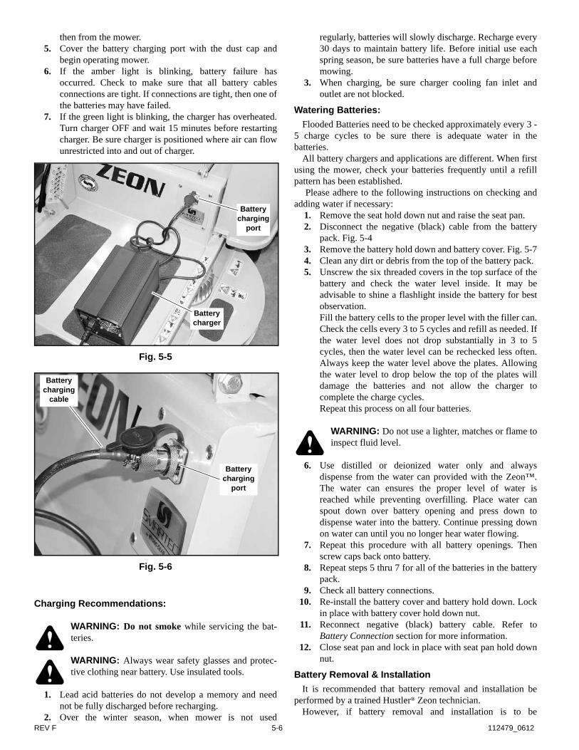
REV F 5-6 112479_0612
then from the mower.5. Cover the battery charging port with the dust cap and
begin operating mower.6. If the amber light is blinking, battery failure has
occurred. Check to make sure that all battery cablesconnections are tight. If connections are tight, then one ofthe batteries may have failed.
7. If the green light is blinking, the charger has overheated.Turn charger OFF and wait 15 minutes before restartingcharger. Be sure charger is positioned where air can flowunrestricted into and out of charger.
Charging Recommendations:
WARNING: Do not smoke while servicing the bat-teries.
WARNING: Always wear safety glasses and protec-tive clothing near battery. Use insulated tools.
1. Lead acid batteries do not develop a memory and neednot be fully discharged before recharging.
2. Over the winter season, when mower is not used
regularly, batteries will slowly discharge. Recharge every30 days to maintain battery life. Before initial use eachspring season, be sure batteries have a full charge beforemowing.
3. When charging, be sure charger cooling fan inlet andoutlet are not blocked.
Watering Batteries:
Flooded Batteries need to be checked approximately every 3 -5 charge cycles to be sure there is adequate water in thebatteries.
All battery chargers and applications are different. When firstusing the mower, check your batteries frequently until a refillpattern has been established.
Please adhere to the following instructions on checking andadding water if necessary:
1. Remove the seat hold down nut and raise the seat pan.2. Disconnect the negative (black) cable from the battery
pack. Fig. 5-43. Remove the battery hold down and battery cover. Fig. 5-74. Clean any dirt or debris from the top of the battery pack.5. Unscrew the six threaded covers in the top surface of the
battery and check the water level inside. It may beadvisable to shine a flashlight inside the battery for bestobservation. Fill the battery cells to the proper level with the filler can.Check the cells every 3 to 5 cycles and refill as needed. Ifthe water level does not drop substantially in 3 to 5cycles, then the water level can be rechecked less often.Always keep the water level above the plates. Allowingthe water level to drop below the top of the plates willdamage the batteries and not allow the charger tocomplete the charge cycles.Repeat this process on all four batteries.
WARNING: Do not use a lighter, matches or flame toinspect fluid level.
6. Use distilled or deionized water only and alwaysdispense from the water can provided with the Zeon™.The water can ensures the proper level of water isreached while preventing overfilling. Place water canspout down over battery opening and press down todispense water into the battery. Continue pressing downon water can until you no longer hear water flowing.
7. Repeat this procedure with all battery openings. Thenscrew caps back onto battery.
8. Repeat steps 5 thru 7 for all of the batteries in the batterypack.
9. Check all battery connections.10. Re-install the battery cover and battery hold down. Lock
in place with battery cover hold down nut.11. Reconnect negative (black) battery cable. Refer to
Battery Connection section for more information.12. Close seat pan and lock in place with seat pan hold down
nut.
Battery Removal & Installation
It is recommended that battery removal and installation beperformed by a trained Hustler® Zeon technician.
However, if battery removal and installation is to be
Fig. 5-5
Fig. 5-6
Battery charging
port
Battery charger
Battery charging
port
Battery charging
cable

112479_0612 5-7 REV F
performed by someone other than a trained Hustler® Zeontechnician, use the following procedures for safe batteryhandling.
Disconnecting the Batteries
Always remove the negative (black) battery cable first. TheZeon is designed with the battery electrically isolated from themower frame. Caution should still be used to prevent tools fromtouching both a battery terminal and the frame.
Remove the nut that holds the cable to the terminal. Place thecable down in the battery compartment beside the battery packso that the connector cannot come in contact with a batteryterminal.
IMPORTANT: Allow five (5) minutes for the controllercapacitors to dissipate their stored energy before you attemptany additional service tasks.
Connecting the Batteries
WARNING: When the negative (black) battery cableis reconnected to the negative battery terminal a sparkwill flash as energy rushes to the control capacitors.Make sure all battery cell caps (covers) are securely inplace and the work area is well ventilated beforeattempting to connect the cable. Keep fingers backfrom the contact point as the spark is very hot.
Attach the cable connector to the battery terminal and installmounting hardware per Fig. 5-8. Torque battery terminal nut to120 in.-lbs. (13.6 Nm). Do not over tighten as this could damagethe battery.
Battery Storage
To maximize battery life it is best to fully charge batteriesshortly after each use.
IMPORTANT: If the mower is to be stored for longer than 30days the batteries should be isolated from the vehicle controlsby using the charging adapter that is supplied with the machine.
Check the batteries water level and replenish if necessary beforestoring.
The Hustler® Zeon charger will need to be disconnected fromthe Zeon charge port after 21 to 22 hours of charge time whetherthe charge light is on or off. Failure to do so may overcharge thebatteries and may drop the water level below the top of theplates.
All batteries self discharge over time.It is required that the battery pack be charged for a
minimum of 21 to 22 hours every 30 days. Failure tomaintain the battery charge level will void the batterywarranty.
Charging adapter
To connect the charging adapter to the batteries and chargingport use the following procedures:
1. Remove the seat pan lock down nut and raise the seatpan.
2. Remove the battery hold down and battery cover.Fig. 5-10
3. Unplug the tractor harness four prong connector from thecharging port connector. Fig. 5-10
4. Disconnect the negative (black) battery cable from thenegative battery terminal on the rear battery (rear rightbattery terminal). Fig. 5-10
5. Disconnect the positive (red) battery cable from thepositive battery terminal on the front battery (front leftbattery terminal). Fig. 5-10
6. Connect the charging adapter black wire to the negativebattery terminal. Then, connect the red wire to thepositive battery terminal. Fig. 5-11
7. Connect the charging adapter to the charger portconnector. Fig. 5-12
8. Re-install the battery cover and battery hold down.Fig. 5-11
9. Close seat pan and re-install seat pan hardware.To disconnect the charging adapter from the batteries and
charging port use the following procedures:1. Remove the seat pan lock down nut and raise the seat
pan.2. Remove the battery hold down and battery cover.
Fig. 5-113. Disconnect the charging adapter from the charger port
connector. Fig. 5-12
Fig. 5-7
Negative battery cable (black)
Battery cover
Battery hold down
Battery hold down nut
Fig. 5-8
Battery cable
Battery stud Nylock Nut Torque to
120 in.-lbs. (13.6 Nm)
Flat washer

REV F 5-8 112479_0612
4. Disconnect the charging adapter black wire from thenegative battery terminal. Then, disconnect the red wirefrom the positive battery terminal. Fig. 5-11
5. Connect the tractor harness four prong connector to thecharging port connector. Fig. 5-10
6. Check all battery connections. Tighten any loosehardware. Torque battery terminal nuts to 120 in.-lbs. Donot overtighten as this could damage the battery. Fig. 5-8
7. Check battery water level. Service as required.8. Connect the positive (red) battery cable to the positive
battery terminal on the front battery (front left batteryterminal). Fig. 5-10
9. Make sure that the connecting hardware is placed on thebattery terminal as shown in Fig. 5-8. Torque nut to 120in.-lbs. Do not overtighten as this could damage thebattery.
10. Re-install the battery cover and battery hold down.Fig. 5-10
11. Connect the negative (black) battery cable to the negativebattery terminal on the rear battery (rear right batteryterminal). Fig. 5-10Make sure that the connecting hardware is placed on thebattery terminal as shown. Torque nut to 120 in.-lbs. Donot overtighten as this could damage the battery. Fig. 5-8
WARNING: When the negative (black) battery cableis reconnected to the negative battery terminal a sparkwill flash as energy rushes to the control capacitors.Make sure all battery cell caps (covers) are securely inplace and the work area is well ventilated beforeattempting to connect the cable. Keep fingers backfrom the contact point as the spark is very hot.
12. Close seat pan and re-install seat pan hardware.
WARNING: Make sure seat pan is securely bolteddown prior to each use to prevent seat from moving/tilting in the event of mower tipping or rollover.
Fig. 5-9
Fig. 5-10
Battery cover
Battery hold down
Negative (black) battery cable
Positive (red) battery cable
Charging port four prong connector
Tractor harness four prong connector

112479_0612 5-9 REV F
Fig. 5-11
Fig. 5-12
Battery cover
Battery hold down
Charging adapter black wire
Charging adapter red wire
Charging adapter
Charging adapter four
prong connector
Charging port four prong connector
Red wire
Black wire

REV F 5-10 112479_0612

112479_0612 6-1 REV F
TROUBLESHOOTING
SYMPTOMS PROBABLE CAUSES SUGGESTED REMEDIES
If error codes are showing on the digital display
Numerous
Refer to the Digital Display Codes Chart in the Electrical System section
Contact your Hustler®
Dealer
There is abnormal vibration
The cutting blade(s) is/are bent or unbalanced
Install new cutting blade(s)
A blade mounting bolt is loose
Tighten the blade mounting bolt
Numerous Contact your Hustler®
Dealer
Uneven cutting height
The blade(s) are not sharp Sharpen the blades
A cutting blade(s) is/are bent
Install new cutting blade(s)
The deck is not level
Level the deck per the Deck leveling and height adjustment section of the parts manual
An anti-scalp wheel is not set correctly
Adjust the height of the anti-scalp wheel
The underside of the deck is dirty
Clean the underside of the deck
Tires improperly inflated Adjust air pressure to 8 - 12 psi (55-83 KPa)
A blade spindle is bent Contact your Hustler®
Dealer
Loss of deck operation
If deck control does not provide visible codes to the Digital Display and the deck fails to operate with fully charged batteries
Contact your Hustler®
dealer

REV F 6-2 112479_0612

112479_0612 7-1 REV F
STORAGE
When storing the unit at the end of the mowing season, the following steps should be taken to ensure readiness for the next mowingseason.
1. Remove all grass, dirt, and trash from mower. Cleanmower and touch up all scrapes with Hustler® spraypaint.IMPORTANT: Wash the machine with a mild detergentand water. Do not pressure wash the machine. Avoidexcessive use of water, especially near the control panel.
2. Check thoroughly for any worn or damaged parts thatneed replacing and order them from your dealer.
3. Thoroughly lubricate machine, according to lubricationinstructions.
4. Fully charge and service the batteries.5. Block machine up so weight is off tires.6. Do not deflate tires.7. The mower should be stored in a well ventilated, clean
and dry place as the battery charger can not be used in awet environment. Connect the battery charger to thecharger port.a. Always keep the batteries fully charged. Especially
important to prevent battery damage when thetemperature is below 32°F (0°C).
b. Attach the charger adapter to the charging port andthe batteries per the Charging Adapter section in theElectrical System chapter.
c. Plug the charger into a proper electrical outlet. Referto Battery Charger, Battery Charging and Charging
Recommendations sections of the Electrical Systemchapter for more details on using the charger andcharging the batteries.
d. For additional information on battery storage refer tothe Battery Storage section of the Electrical Systemchapter of this manual.
New season preparationBefore starting the mower following post season storage, the
following servicing is required:1. Clean machine, removing trash and dirt accumulation.2. Tighten any bolts that have loosened and make sure all
hair pins, cotter pins and clevis pins are in place.3. Install all safety shields and covers and review safety
precautions listed in this manual.4. Check and inflate tires to 8-12 psi (55-83 KPa).5. Attach the tractor harness to the charging port and the
batteries per the Charging Adapter section in theElectrical System chapter.
6. Close seat pan and re-install seat pan hardware.
WARNING: Make sure seat pan is securely bolteddown prior to each use to prevent seat from moving/tilting in the event of mower tipping or rollover.
PRODUCT LITERATURE
If you would like to view or print a copy of the Hustler® Zeon product manuals go online to www.hustlerturf.com and click on theMANUALS button.

REV F 7-2 112479_0612

112479_0612 i-1 REV F
INDEXPAGE PAGE
Anti-scalp wheels . . . . . . . . . . . . . . . . . . . . . . . . . . . 3-9
Battery Charge Level Indicator . . . . . . . . . . . . . . . . . 5-1
Battery Charger . . . . . . . . . . . . . . . . . . . . . . . . . . . . 5-3
Battery Charging . . . . . . . . . . . . . . . . . . . . . . . . . . . 5-5
Battery Charging Port . . . . . . . . . . . . . . . . . . . . . . . . 5-3
Battery Connectors . . . . . . . . . . . . . . . . . . . . . . . . . 5-5
Battery Disconnection . . . . . . . . . . . . . . . . . . . . . . . 5-7
Battery Maintenance . . . . . . . . . . . . . . . . . . . . . . . . 5-5
Battery Removal & Installation . . . . . . . . . . . . . . . . . 5-6
Battery Safety . . . . . . . . . . . . . . . . . . . . . . . . . . . . . . 5-4
Charging adapter . . . . . . . . . . . . . . . . . . . . . . . . . . . 5-7
Charging Recommendations . . . . . . . . . . . . . . . . . . 5-6
Children . . . . . . . . . . . . . . . . . . . . . . . . . . . . . . . . . . 3-3
Codes . . . . . . . . . . . . . . . . . . . . . . . . . . . . . . . . . . . . 5-2
Component Maintenance . . . . . . . . . . . . . . . . . . . . . 5-1
Control Panel . . . . . . . . . . . . . . . . . . . . . . . . . . . . . . 3-3
Controls . . . . . . . . . . . . . . . . . . . . . . . . . . . . . . . . . . 3-3
Deck cutting height adjustment . . . . . . . . . . . . . . . . 3-9
Digital Display . . . . . . . . . . . . . . . . . . . . . . . . . . . . . 5-1
Digital Display Codes . . . . . . . . . . . . . . . . . . . . . . . . 5-2
Driving the mower . . . . . . . . . . . . . . . . . . . . . . . . . . 3-6
Electical System Safety . . . . . . . . . . . . . . . . . . . . . . 5-1
Electrical system . . . . . . . . . . . . . . . . . . . . . . . . . . . 4-2
Electrical System Information . . . . . . . . . . . . . . . . . . 5-1
Fail Safe Brake . . . . . . . . . . . . . . . . . . . . . . . . . . . . . 3-3
Hustler® Zeon Maintenance Locator Chart . . . . . . . 4-6
Hustler® Zeon Maintenance Schedule . . . . . . . . . . 4-5
Lubrication . . . . . . . . . . . . . . . . . . . . . . . . . . . . . . . . 4-2
Maintenance & Adjustments Introduction . . . . . . . . . 4-1
Model and serial number . . . . . . . . . . . . . . . . . . . . . 1-1
Moving mower . . . . . . . . . . . . . . . . . . . . . . . . . . . . . 3-5
Mower blade installation . . . . . . . . . . . . . . . . . . . . . 4-3
Mower blade maintenance . . . . . . . . . . . . . . . . . . . 4-2
Mower blade removal . . . . . . . . . . . . . . . . . . . . . . . 4-3
Mower deck operation . . . . . . . . . . . . . . . . . . . . . . . 3-9
New season preparation . . . . . . . . . . . . . . . . . . . . . 7-1
Operating suggestions . . . . . . . . . . . . . . . . . . . . . . 3-7
Operation . . . . . . . . . . . . . . . . . . . . . . . . . . . . . . . . . 3-1
Parts and service . . . . . . . . . . . . . . . . . . . . . . . . . . . 1-1
ROPS (Roll Over Protective Structure) . . . . . . . . . . 3-5
Safe Operating Practices . . . . . . . . . . . . . . . . . . . . 3-1
Safe Servicing Practices . . . . . . . . . . . . . . . . . . . . . 4-1
Safety and Instruction Decals . . . . . . . . . . . . . . . . . 2-1
Safety start interlock system . . . . . . . . . . . . . . . . . . 3-3
Seat adjustment . . . . . . . . . . . . . . . . . . . . . . . . . . . 4-2
Service . . . . . . . . . . . . . . . . . . . . . . . . . . . . . . . . . . 4-1
Service Indicator Light / Service Indicator Symbol . 5-2
Slope operation . . . . . . . . . . . . . . . . . . . . . . . . . . . . 3-2
Steering control lever adjustment . . . . . . . . . . . . . . 4-2
Stopping the traction drive system . . . . . . . . . . . . . 3-5
Tires . . . . . . . . . . . . . . . . . . . . . . . . . . . . . . . . . . . . 4-2
To the new owner . . . . . . . . . . . . . . . . . . . . . . . . . . 1-1
Torque values . . . . . . . . . . . . . . . . . . . . . . . . . . . . . 4-2
Traction drive system starting . . . . . . . . . . . . . . . . . 3-4
Troubleshooting . . . . . . . . . . . . . . . . . . . . . . . . . . . . 6-1
Using a ramp . . . . . . . . . . . . . . . . . . . . . . . . . . . . . . 3-2
Using this manual . . . . . . . . . . . . . . . . . . . . . . . . . . 1-1
Warranty registration . . . . . . . . . . . . . . . . . . . . . . . . 1-1
Watering Batteries . . . . . . . . . . . . . . . . . . . . . . . . . . 5-6