hv accessories design, testing and installation ... · hv accessories design, testing and...
TRANSCRIPT
HV Accessories HV Accessories Design, Testing and Installation Design, Testing and Installation
RecommendationsRecommendations
Henk Geene Pirelli Cables and Systems N.V.

Prefabricated/prePrefabricated/pre--molded HV and EHV molded HV and EHV JointsJoints
• Slip-over joints (or cold shrink joints)– single piece – three piece joints
• Composite joints • Plug-in joints• Heat shrink joints (for the lower range)

3 piece slip3 piece slip--over jointover joint
•Rubber sleeve adapters, rubber insulator
•Interfaces between cable/rubber and rubber/rubber
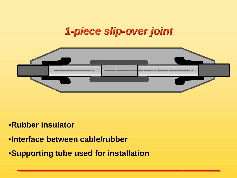
11--piece slippiece slip--over jointover joint
•Rubber insulator
•Interface between cable/rubber
•Supporting tube used for installation
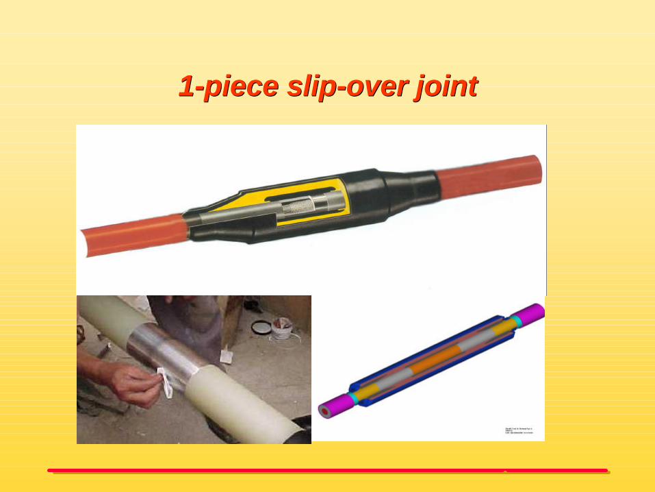
11--piece slippiece slip--over jointover joint
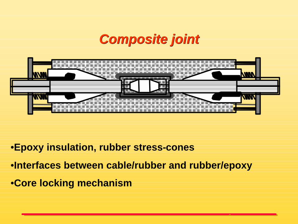
Composite jointComposite joint
•Epoxy insulation, rubber stress-cones
•Interfaces between cable/rubber and rubber/epoxy
•Core locking mechanism

Composite jointComposite joint
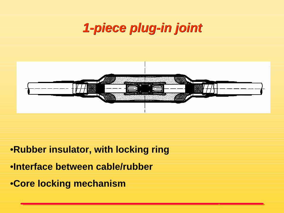
11--piece plugpiece plug--in jointin joint
•Rubber insulator, with locking ring
•Interface between cable/rubber
•Core locking mechanism
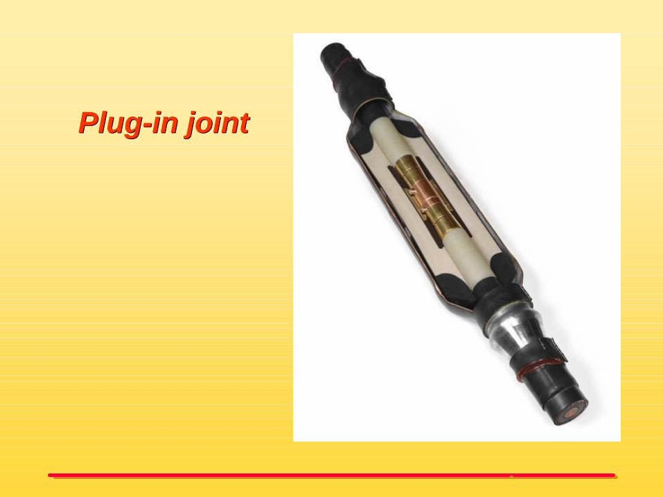
PlugPlug--in jointin joint

Connecting different cable sizesConnecting different cable sizes

Joint coveringJoint covering
Copper casing, plastic outer sheath
Coffin box with filling compound
Flexible covering
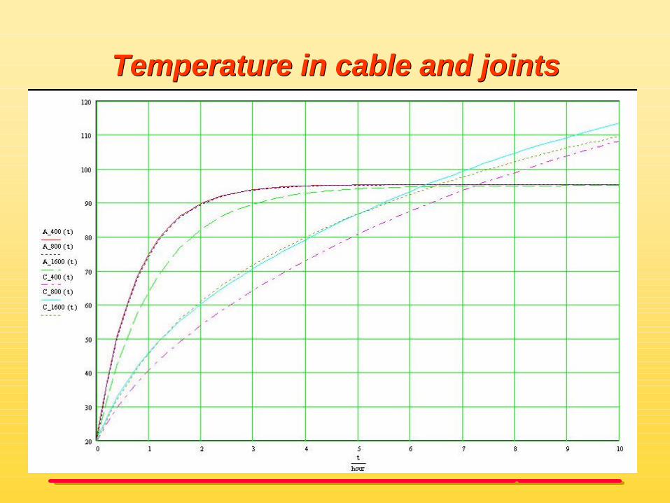
Temperature in cable and jointsTemperature in cable and joints

Joints submerged in waterJoints submerged in water

Special bonding of jointsSpecial bonding of joints
Concentric bonding cable
Single core bonding cable

Concentric cable versus single core Concentric cable versus single core bonding cablesbonding cables

TerminationsTerminations
• Outdoor terminations– Porcelain terminations– Composite terminations
• Switch gear terminations (according to IEC60859)– Fluid filled type – Dry type
• Switch gear terminations– Fluid filled type – Dry type
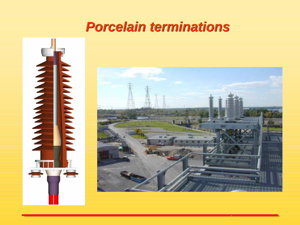
Porcelain terminationsPorcelain terminations

Composite outdoor Composite outdoor terminationtermination
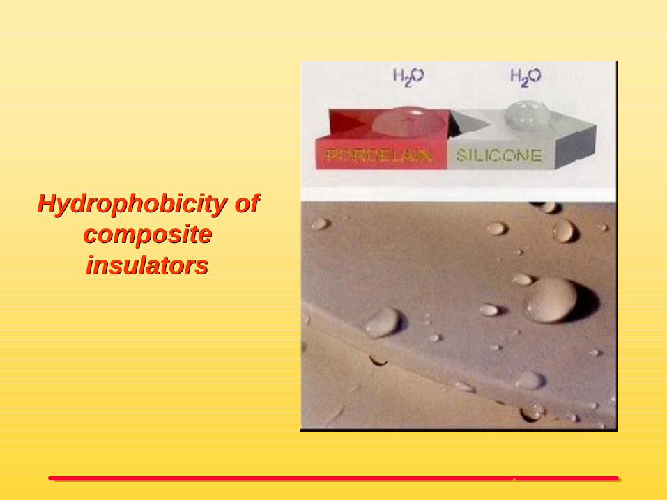
HydrophobicityHydrophobicity of of composite composite insulatorsinsulators

StressStress--conecone

Dry GIS terminationsDry GIS terminations

GIS and transformer terminationsGIS and transformer terminations
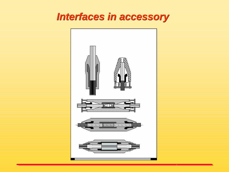
Interfaces in accessoryInterfaces in accessory

Interface parametersInterface parameters
• smoothness of the surfaces
• contact pressure on the interface
• type of lubricant in the interface
• electrical field distribution in the interface
• temperature and temperature changes
• quality of accessory installation

Electrical interface strength versus interface Electrical interface strength versus interface pressure and surface smoothnesspressure and surface smoothness
interface pressure, surface smoothness
E
Rz=const.
x
y
z
XLP
ES
IR
p
elec
tric
al in
terf
ace
stre
ngth
(nearly) nocavities
(nearly) onlycavities
material strength
electricalstrength of air
transitionzone

Surface smoothness as a result of Surface smoothness as a result of emeryemery--cloth with different gradescloth with different grades
Grade 220
Grade 400
Grade 400p

EffectEffect of lubricant oil on the breakdown of lubricant oil on the breakdown strength of a typical XLPEstrength of a typical XLPE--SIR interfaceSIR interface
breakdown strength E
brea
kdow
n pr
obab
ility
1
5
10
20
40
60
80%99
405 10 15 20 25 kV/mm
E0 = 9,1 kV/mmslope b = 9,8
with lubricantwithout lubricant
5,9E0 = 23,7 kV/mmslope b = 5,9

Long term performance of interfaces Long term performance of interfaces in cable accessoriesin cable accessories
• Migration of the lubricant• Movements in the interface• Reduction of the interface pressure due to relaxation of materials• electrical ageing of interfaces• contamination of the interface
•Change in one or more parameters leading to a decrease of the electrical withstand strength of the interface.
•Intrinsic electrical ageing of the applied materials in interfaces is negligible.
•Ageing though mechanical and thermo-mechanical effects causing the formation of cavities, followed by partial discharges.
Ageing of interfaces
Formation of cavities

Recommendations and conclusionsRecommendations and conclusions
Accessory design• Tight fit between cable and accessory or between other insulating bodies
under different operating conditions. • A proper interface design does not allow partial discharges.
System design• Mechanical and thermo-mechanical behaviour of the accessories and the
interaction with its environment has to be taken into account• Long term test or prequalification tests of the cable system• For HV and EHV should be installed by skilled jointers.• In case of partial discharges: the trend analyses by means of online
partial discharge monitoring can give indication of remaining lifetime
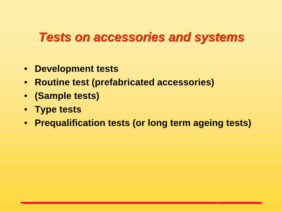
Tests on accessories and systemsTests on accessories and systems
• Development tests• Routine test (prefabricated accessories)• (Sample tests)• Type tests • Prequalification tests (or long term ageing tests)

Development testsDevelopment tests
• Model tests• Statistical (breakdown) tests• Mechanical tests• Thermal tests• Thermo mechanical tests• Long term ageing tests

Impulse Impulse breakdown tests breakdown tests
on jointson joints
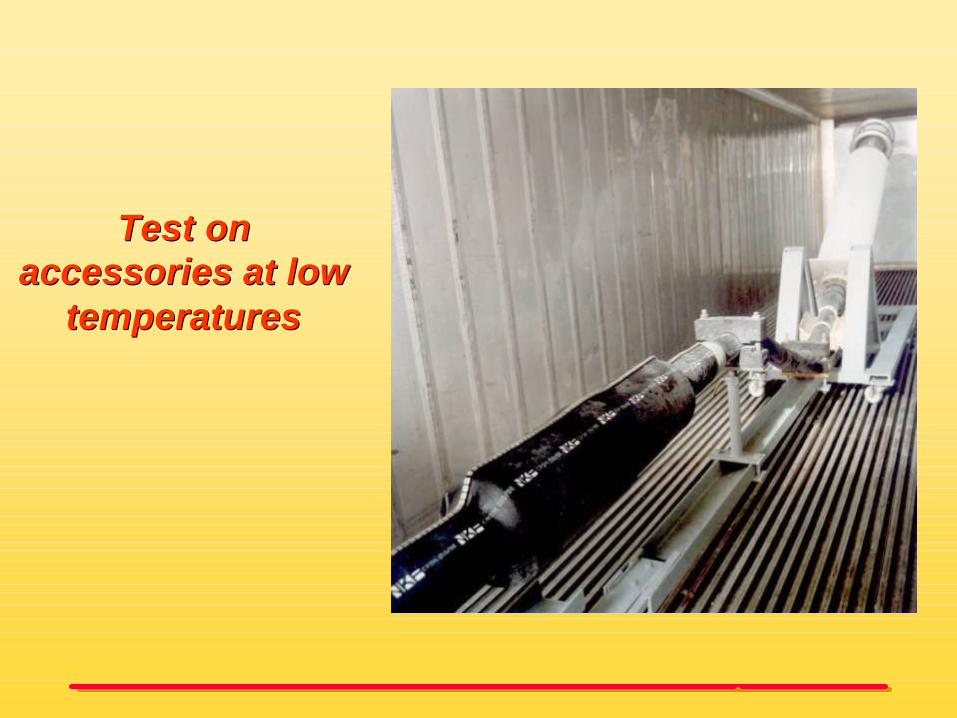
Test on Test on accessories at low accessories at low
temperaturestemperatures

ShortShort--circuit test on a complete systemcircuit test on a complete system

Routine test program HV and EHV accessoriesRoutine test program HV and EHV accessories
Non electrical routine test• visual inspection• check on dimension
Electrical routine test• Partial discharge test (e.g. at 1.7Uo): no partial
discharges allowed (sensitivity < 3-5 pC)• AC-voltage test (e.g. at 2.5 Uo for 30min)

Electrical routine Electrical routine test on test on
joint insulatorsjoint insulators
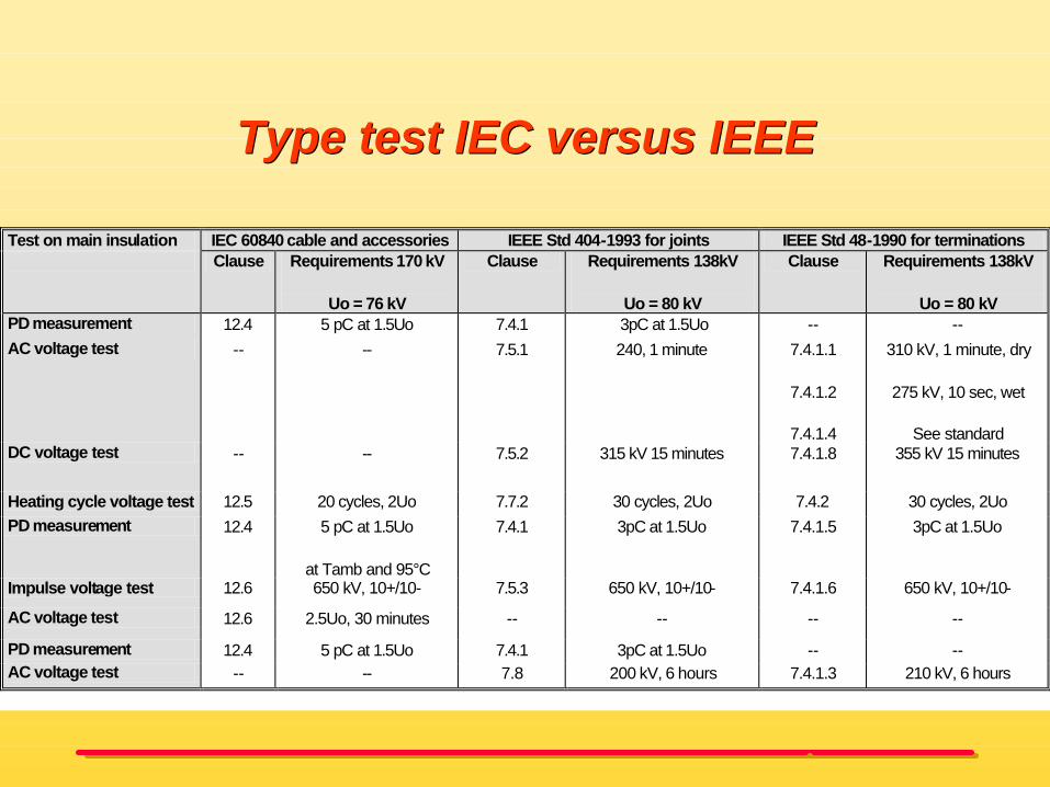
Type test IEC versus IEEEType test IEC versus IEEE
Test on main insulation IEC 60840 cable and accessories IEEE Std 404-1993 for joints IEEE Std 48-1990 for terminations Clause Requirements 170 kV
Uo = 76 kV
Clause Requirements 138kV
Uo = 80 kV
Clause Requirements 138kV
Uo = 80 kV PD measurement 12.4 5 pC at 1.5Uo 7.4.1 3pC at 1.5Uo -- -- AC voltage test --
-- 7.5.1 240, 1 minute 7.4.1.1
7.4.1.2
7.4.1.4
310 kV, 1 minute, dry
275 kV, 10 sec, wet
See standard DC voltage test -- -- 7.5.2 315 kV 15 minutes 7.4.1.8 355 kV 15 minutes
Heating cycle voltage test 12.5 20 cycles, 2Uo 7.7.2 30 cycles, 2Uo 7.4.2 30 cycles, 2Uo PD measurement 12.4 5 pC at 1.5Uo
at Tamb and 95°C
7.4.1 3pC at 1.5Uo 7.4.1.5 3pC at 1.5Uo
Impulse voltage test 12.6 650 kV, 10+/10- 7.5.3 650 kV, 10+/10- 7.4.1.6 650 kV, 10+/10-
AC voltage test 12.6 2.5Uo, 30 minutes -- -- -- --
PD measurement 12.4 5 pC at 1.5Uo 7.4.1 3pC at 1.5Uo -- -- AC voltage test -- -- 7.8 200 kV, 6 hours 7.4.1.3 210 kV, 6 hours

Typical type test arrangementTypical type test arrangement for a 400kV for a 400kV XLPE cable systemXLPE cable system
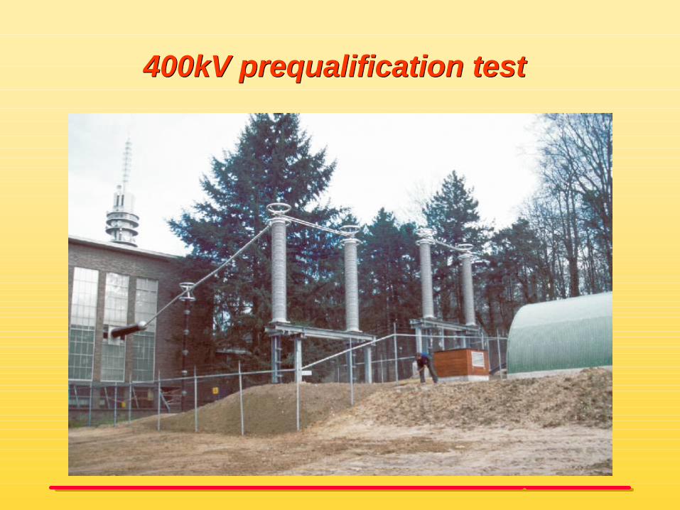
400kV prequalification test 400kV prequalification test

Installation recommendations for Installation recommendations for accessories (in a system)accessories (in a system)
• Flexible installation• Rigid installation• Clamping cables under terminations
Most of the forces acting on the accessories are induced by the cable:
•Thermo-mechanical forces caused by the load current
•Short circuit forces

Measurement of cable thrust forcesMeasurement of cable thrust forces

““Thrust” forces during heating cyclesThrust” forces during heating cycles
0
F[kN]
Tcond [ºC]Heating cycles to Tcond 100ºCTamb
1st cycle20th cycle

Transition between flexible and rigid Transition between flexible and rigid installationinstallation
Test set-up

Cable movement and related forces Cable movement and related forces during heating and coolingduring heating and cooling

Rigid versus flexible installationRigid versus flexible installation
Direct buriedOther installation systems
simplecable supports on large
distances (4-10m)
complexcable clamped on short
distances (0.5-1m)
Cable fixation
highlowCable movements
lowhighThrust forces
FlexibleRigid
Duct systems

Rigid installation during testRigid installation during test

Flexible tunnel Flexible tunnel installationinstallation

Flexible shaft installationFlexible shaft installation

Rigid installation of cable/jointsRigid installation of cable/joints
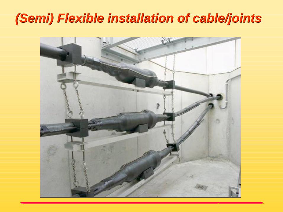
(Semi) Flexible installation of cable/joints(Semi) Flexible installation of cable/joints

Clamping of cable below terminationsClamping of cable below terminations

Clamping below Clamping below terminations terminations