hvac and leed - fayoumfayoum.edu.eg/stfsys/stffiles//243//2512//7-gear... · 2016-05-05 · 23 gear...
TRANSCRIPT
18
Gear Measurement
3. Gear profile checking
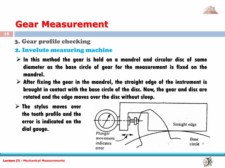
2. Involute measuring machine
In this method the gear is held on a mandrel and circular disc of same
diameter as the base circle of gear for the measurement is fixed on the
mandrel.
After fixing the gear in the mandrel, the straight edge of the instrument is
brought in contact with the base circle of the disc. Now, the gear and disc are
rotated and the edge moves over the disc without sleep.
The stylus moves over
the tooth profile and the
error is indicated on the
dial gauge.
Lecture (7) – Mechanical Measurements
19
Gear Measurement
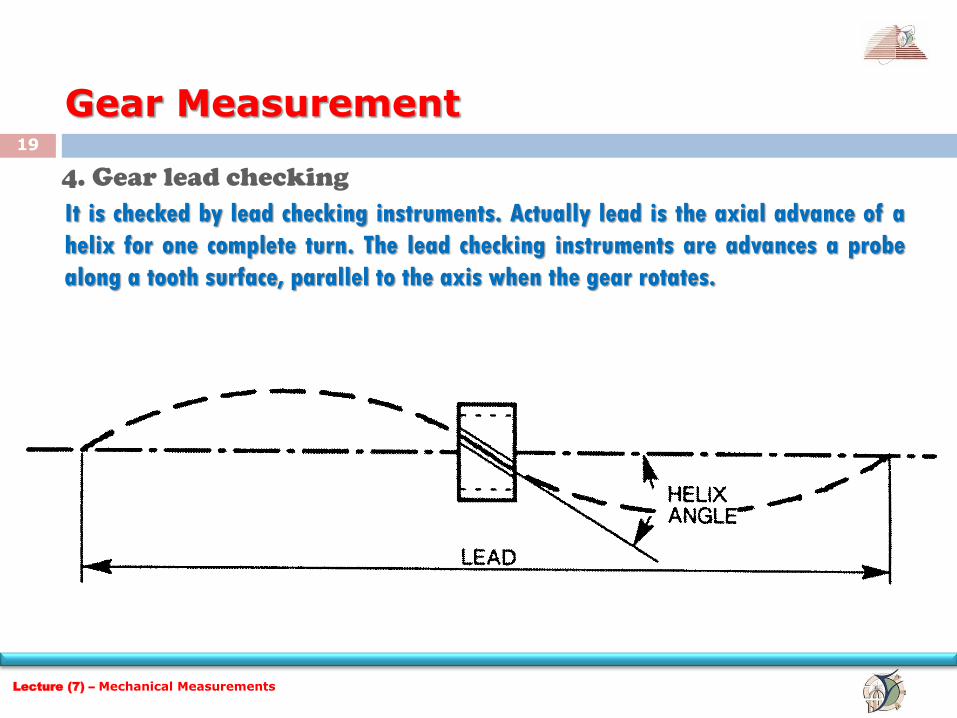
4. Gear lead checking
It is checked by lead checking instruments. Actually lead is the axial advance of a
helix for one complete turn. The lead checking instruments are advances a probe
along a tooth surface, parallel to the axis when the gear rotates.
Lecture (7) – Mechanical Measurements
20
Gear Measurement
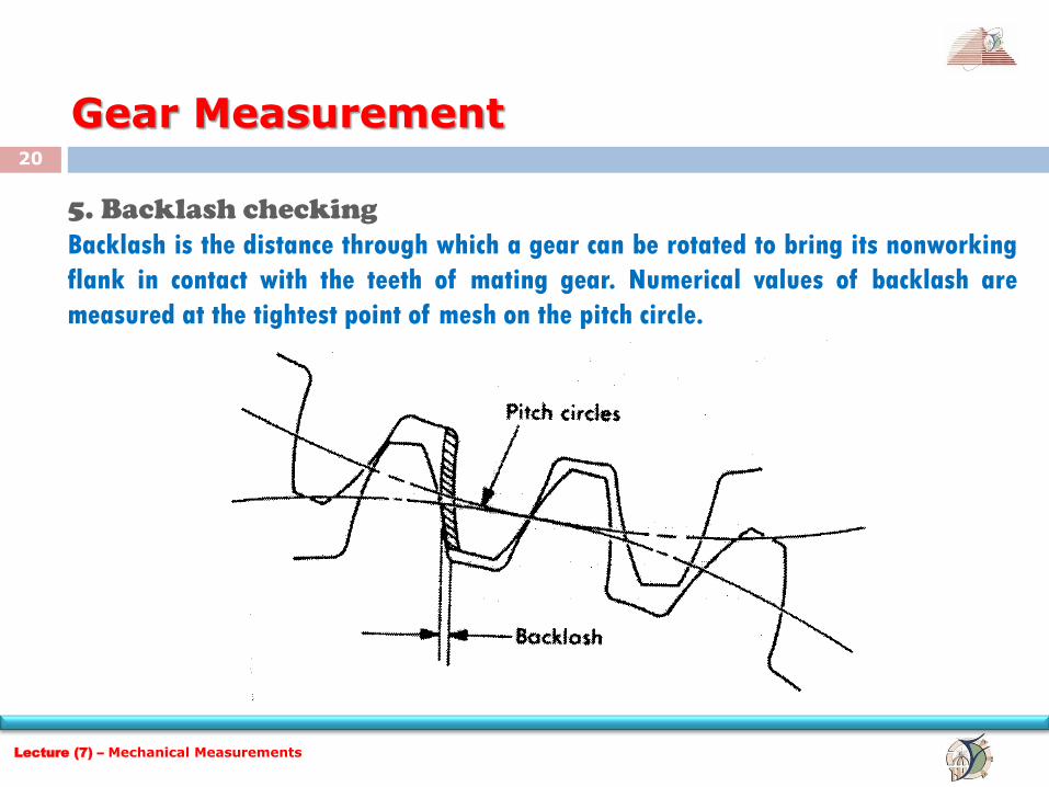
5. Backlash checking
Backlash is the distance through which a gear can be rotated to bring its nonworking
flank in contact with the teeth of mating gear. Numerical values of backlash are
measured at the tightest point of mesh on the pitch circle.
Lecture (7) – Mechanical Measurements
21
Gear Measurement
There are two types of backlash
1. Circumferential backlash
2. Normal backlash
The determination of backlash is, first one of the two gears of the pair is locked,
while other is rotated forward and backward and by the comparator the maximum
displacement is measured. The stylus of comparator is locked near the reference
cylinder and a tangent to this is called circular backlash.
Lecture (7) – Mechanical Measurements
22
Gear Measurement
6. Gear Tooth thickness measurement
Tooth thickness is generally measured at pitch circle and also in most cases the
chordal thickness measurement is carried out i.e. the chord joining the intersection
of the tooth profile with the pitch circle. The methods which are used for measuring
the gear tooth thickness is
1) Gear tooth vernier caliper method (Chordal thickness method)
2) Base tangent method.
3) Constant chord method.
4) Measurement over pins or balls.
Lecture (7) – Mechanical Measurements
23
Gear Measurement
6. Gear Tooth thickness measurement
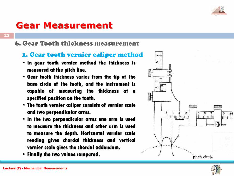
1. Gear tooth vernier caliper method
• In gear tooth vernier method the thickness is
measured at the pitch line.
• Gear tooth thickness varies from the tip of the
base circle of the tooth, and the instrument is
capable of measuring the thickness at a
specified position on the tooth.
• The tooth vernier caliper consists of vernier scale
and two perpendicular arms.
• In the two perpendicular arms one arm is used
to measure the thickness and other arm is used
to measure the depth. Horizontal vernier scale
reading gives chordal thickness and vertical
vernier scale gives the chordal addendum.
• Finally the two values compared.
Lecture (7) – Mechanical Measurements
24
Gear Measurement
7. Measurement of concentricity
In setting of gears the centre about which the gear is mounded should be coincident
with the centre from which the gear is generated. It is easy to check the concentricity
of the gear by mounting the gear between centers and measuring the variation in
height of a roller placed between the successive teeth. Finally the variation in
reading will be a function of the eccentricity present.
8. Alignment checking
It is done by placing a parallel bar between the gear teeth and the gear being
mounted between centers. Finally the readings are taken at the two ends of the bar
and difference in reading is the misalignment.
Lecture (7) – Mechanical Measurements
25
Gear Measurement
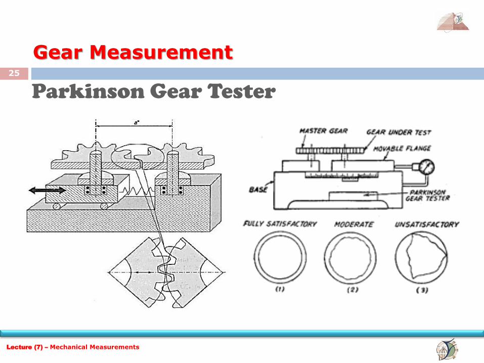
Parkinson Gear Tester
Lecture (7) – Mechanical Measurements
26
Gear Measurement
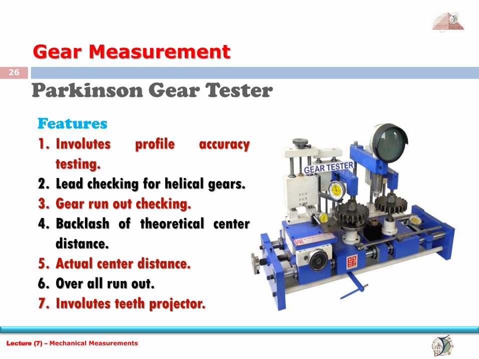
Parkinson Gear Tester
Features
1. Involutes profile accuracy
testing.
2. Lead checking for helical gears.
3. Gear run out checking.
4. Backlash of theoretical center
distance.
5. Actual center distance.
6. Over all run out.
7. Involutes teeth projector.
Lecture (7) – Mechanical Measurements
27
Gear Measurement
Parkinson Gear Tester
Working principle
The master gear is fixed on vertical spindle and the gear to be tested is fixed on
similar spindle which is mounted on a carriage. The carriage which can slide either
side of these gears are maintained in mesh by spring pressure. When the gears are
rotated, the movement of sliding carriage is indicated by a dial indicator and these
variations arc is measure of any irregularities. The variation is recorded in a recorder
which is fitted in the form of a waxed circular chart. In the gears are fitted on the
mandrels and are free to rotate without clearance and the left mandrel move along
the table and the right mandrel move along the spring-loaded carriage. The two
spindles can be adjusted so that the axial distance is equal and a scale is attached to
one side and vernier to the other, this enables center distance to be measured to
within 0.025mm.
Lecture (7) – Mechanical Measurements
28
Gear Measurement
Parkinson Gear Tester
Working principle (continued) If any errors in the tooth form when gears are in close mesh, pitch concentricity of
pitch line will cause a variation in center distance from this movement of carriage as
indicated to the dial gauge will show the errors in the gear test. The recorder also
fitted in the form of circular or rectangular chart and the errors are recorded.
Limitations of Parkinson gear tester:
1. Accuracy ±0.001mm
2. Maximum gear diameter is 300mm
3. Errors are not clearly identified.
4. Measurement dependent upon the master gear.
5. Low friction in the movement of the floating carriage.
Lecture (7) – Mechanical Measurements

29