hvac design considerations for corrosive environments
TRANSCRIPT

HVAC Design Considerations for Corrosive Environments Course No: M03-012
Credit: 3 PDH
A. Bhatia
Continuing Education and Development, Inc. 9 Greyridge Farm Court Stony Point, NY 10980 P: (877) 322-5800 F: (877) 322-4774 [email protected]

HVAC DESIGN CONSIDERATIONS FOR CORROSIVE ENVIRONMENTS
Corrosion alone accounts for approximately 40% of all equipment failures in industrial
facilities. Facilities located in potentially corrosive outdoor environments such as
seacoast, industrial sites, heavily populated urban areas, some rural locations, or
combinations are exposed to various threats of salt laden corrosive elements, various
air borne molecular contaminants (AMC) and water vapor (as a result of high relative
humidity). In addition, some other micro environments laundry facilities, diesel-burning
devices/exhaust piping, sewer vents, traffic, pool areas, water treatment facilities and ,
household cleaning agents etc. can also produce corrosive atmospheres.
Contaminants in an environment typically result in the creation of electrolytes that
facilitate the corrosion process. Electrolytes are substances that are electrically
conductive when dissolved in water. These pollutants, in combination with other
factors such as wind direction, humidity, water, fog, temperature, proximity to pollutant
source, and dust or particle contamination, may result in the premature failure of
equipment. Premature corrosion of air conditioning heat exchangers, specifically
condenser coils can be a serious problem in harsh seaside or industrial environments;
coils installed in these environments have been known to fail in less than a year. The
result is the costly replacement of the coil and/or the entire unit. If these units are
improperly applied or left unprotected, they can experience rapid corrosion from
exposure to aggressive elements. However, measures can be taken to identify
potentially corrosive environments prior to equipment selection.
This course discusses the HVAC design considerations for corrosive environments.
This course is split into 4 sections:
PART I Overview of Corrosion Basics
PART II Identification of Potential Corrosive Environments
PART III Design Standards (ISA)
PART IV HVAC Design Considerations

PART I- OVERVIEW OF CORROSION
Expressed simply, corrosion is the deterioration of metal by reaction with its
environment. More specifically in context with air borne contamination, the corrosion is
defined as the deterioration of metal due to the presence of acid gases in tandem with
elevated humidity and temperatures. Corrosion can proceed in a general manner
(general corrosion) or in a more localized manner (galvanic corrosion, pitting corrosion,
formicary corrosion), depending on conditions and the material systems used.
Galvanic Corrosion: The necessary conditions for galvanic corrosion occur when
dissimilar metals, in contact, are exposed to an electrolyte. Electrolytes are substances
that are electrically conductive when in solution. Common electrolytes may include
chloride contaminants from sources such as seawater, road salts, pool cleaners,
laundry facilities and household cleaning agents. These electrolytes are typically
sodium or calcium chloride-based compounds. An understanding of the environment in
which HVAC/R equipment is being applied is essential to the proper selection of
materials and protection means.
General Corrosion: General corrosion is the degradation of metal caused by a
reaction with the surrounding environment. Since general corrosion consumes metal
and typically forms metal oxides, unsightly surface conditions usually result. As an
example, copper is susceptible to attack from sulfur-containing gases. Unprotected
metal will continue to react with the contaminant resulting in corrosion. Under severe,
prolonged conditions, the metal continues to corrode until the integrity of the material
and equipment is jeopardized. Unprotected copper tubes in polluted industrial
environments can lead to tube leaks and failure of the refrigeration system. Sulfur and
nitrogen based electrolytes in combination with chloride environments are often the
cause of accelerated corrosion of these metals.
Understanding Problem
In process sensitive areas like server rooms, control rooms, and data centers, large
quantity of microprocessor-based equipment is present. Given the harsh climates and
diverse industrial environments, these sensitive areas are exposed to multiple threats,
such as fire, dust particles, gaseous contamination, temperature and humidity.
To an extent, the HVAC design is meeting the challenge posed by fire, humidity,
temperature and dust particulate contamination. Unfortunately, the potential damage
to electronic equipment caused by the corrosive effects of gaseous contaminants has
been largely ignored. Since the problem of corrosion is primarily due to air borne
molecular contaminants (AMC), proper design guidelines mandate the removal of all
such contaminants from the air stream. Not all the locations are same; the ambient
conditions need to be carefully assessed before deciding on the HVAC design.
In today's business environment, a company’s dependence on its information & data
processing systems is un- debatable. Corrosive gasses can damage these systems
that can have crippling effects both on cost and productivity. The common fault
occurrences could be:
• Erroneous information;
• Interrupted operations;
• Sporadic electrical hiccups ;
• Ghost signals;
• Lost data;
• Loss of ferromagnetism (stored information) on disc drives;
• Mechanical failure (head crashes, wear) can occur on data tracks;
• Damage to pin connectors on circuit boards, IC plug-in sockets and wire wrap
connections;
• Disruption of electric current & circuit failure.
In extreme cases, corrosion may lead to prolonged disruption or even complete
shutdown of an entire process operation. Replacing damaged electronic components
can substantially increase the operational costs.
To preclude any potential damage to electronic equipment and to avoid any
acrimonious debates over warranty coverage, and, more importantly, to ensure there
is no loss of system’s integrity in the first place, the sensitive areas should be
protected by effective air filtration systems.
The severity of the environment (i.e., humidity, temperature, types and levels of gases)
will determine the speed of failure. The importance of knowing and preventing
corrosion is thus very important.
HOW CORROSION OCCURS
All the metals have specific relative electrical potential. When metals of different
electrical potential are in contact in the presence of moisture, a low-energy electric

current flow from the metal having high (least noble) position in the galvanic series to
the one having the lower (most noble) position. This phenomenon, called galvanic
action, is a direct contributor to the material degradation, or corrosion, of metals.
Moisture in air or humidity is conduit to corrosion.
Root Causes
The principal cause of corrosion is elevated humidity and/or temperatures in the
presence of contaminant gases. These conditions alone or in combination, tend to
accelerate the natural corrosion process in metals and electronic chips.
Humidity: Moisture in air can be considered the lifeblood of galvanic corrosion. A
galvanic corrosion cell requires an electrolyte or current carrying media, to reach a
dynamic state. The electrolyte can be water or any water-soluble substance with good
conducting properties. Moisture in the air is one such electrolyte. Humid air
contaminated with corrosive gasses further accelerates the corrosion rate as the air’s
current carrying potential increases.
Temperature: Chemical reactions in general are temperature sensitive, with increased
temperature normally resulting in a faster reaction rate. It has been established that
corrosion is essentially chemical in nature: its severity will also be influenced by
temperature. This being the case in this instance, the corrosion rate of control
equipment increases with a rise in temperature. By strictly controlling temperature and
humidity, the conditions favorable to corrosion can be diminished. This represents one
essential component of corrosion control.
Corrosive Gases: Not all gases cause corrosion. Specifically, we are concerned with
three types of gases:
1. Acidic gases, such as hydrogen sulfide, sulfur oxides, chlorine, hydrogen
fluoride (HF) and nitrogen oxides;
2. Caustic gases, such as ammonia;
3. Oxidizing gases, such as ozone
Of the gases that can cause corrosion, the acidic gases are typically the most harmful.
For instance, it takes only 10 parts per billion (ppb) of chlorine to inflict the same
amount of damage as 25,000 ppb of ammonia.

PART II- POTENTIALLY CORROSIVE ENVIRONMENTS
Potentially corrosive outdoor environments include areas adjacent to the seacoast,
industrial sites, heavily populated urban areas, some rural locations, or combinations
of any of these environments. Factors including but not limited to the presence of flue
gas, sewage vents or open sewage systems and diesel exhaust can all have a
detrimental effect on electronic equipment and HVAC/R coils.
Coastal/Marine
Coastal or marine environments are characterized by the abundance of sodium
chloride (salt) which is carried by sea spray, mist or fog. Most importantly, this salt
water can be carried more than several miles by ocean breezes and tidal currents. It is
not uncommon to experience salt-water contamination as far away as 5 miles from the
coast. As a result, protection of HVAC equipment from ocean-borne electrolytes in
inland areas may be necessary.
Line-of-sight distance from the ocean, prevailing wind direction, relative humidity,
wet/dry time, and coil temperature will determine the severity of corrosion potential in
the coastal environment. If the condenser coil faces the ocean or faces into the
prevailing winds from the coast, there is a high probability of seawater contamination.
Appropriate protection is strongly recommended.
Industrial
Industrial applications are associated with a host of diverse conditions with the
potential to produce various atmospheric emissions. Sulfur and nitrogen oxide
contaminants are most often linked to industrial and high-density urban environments.
Combustion of coal and fuel oils releases sulphur oxides (SO2, SO3 ) and nitrogen
oxides (NOx ) into the atmosphere. These gases accumulate in the atmosphere and
return to the ground in the form of acid rain or low pH dew.
Not only are industrial emissions potentially corrosive, many industrial dust particles
can be laden with harmful metal oxides, chlorides, sulfates, sulfuric acid, carbon, and
carbon compounds. These particles, in the presence of oxygen, water, or high
humidity environments can be highly corrosive and may lead to many forms of
corrosion including general corrosion and localized corrosion such as pitting and
formicary corrosion.

INDUSTRIAL PLANT ANTICIPATED GASEOUS CONTAMINANTS
Aluminum Plants
Chlorine
Hydrogen Chloride
Hypochlorous Acid
Hydrogen Fluoride
Oxides of Sulphur
Oxides of Nitrogen
Hydrocarbons
Cl2
HCl
HOCl
HF
SOx
NOx
CxHx
Fertilizer Plants
Ammonia
Hydrogen Fluoride
Hydrocarbons
NH3
HF
CxHx
Petroleum & Chemical
Plants
Hydrogen Sulphide
Oxides of Sulphur
Oxides of Nitrogen
Hydrocarbons
Organics
H2S
SOx
NOx
CxHx
*
Mining & Metallurgy Oxides of Sulphur
Oxides of Nitrogen
SOx
NOx
Power Generation
Oxides of Sulphur
Oxides of Nitrogen
Hydrocarbons
Organics
SOx
NOx
CxHx
*
Paper & Pulp
Manufacturing
Chlorine
Hydrogen Chloride
Hypochlorous Acid
Hydrogen Sulphide
Oxides of Sulphur
Oxides of Nitrogen
Organics
Cl2
HCl
HOCl
H2S
SOx
NOx
*
Sewage Treatment Hydrogen Sulphide
Ammonia
Hydrocarbons
Organics
H2S
NH3
CxHx
*

INDUSTRIAL PLANT ANTICIPATED GASEOUS CONTAMINANTS
Steel Plants
Hydrogen Chloride
Hydrogen Fluoride
Hydrogen Sulphide
Oxides of Sulphur
Oxides of Nitrogen
HCl
HF
H2S
SOx
NOx
Combination Marine/Industrial
Salt-laden seawater mist, combined with the harmful emissions of an industrial
environment, poses a severe threat. The combined effects of salt mist and industrial
emissions will accelerate corrosion. Internally in manufacturing plants, corrosive
gases may be result of process chemicals or the typical industrial processed employed
in manufacturing activities for instance in semiconductor chip facility. Open sewage
systems, vents, diesel exhaust, emissions from dense traffic, land fills, aircraft and
ocean vessel exhaust, industrial manufacturing, chemical treatment facilities (cooling
tower proximity), and fossil fuel burning power plants are potential contributors to
consider.
Urban
Highly populated areas generally have high levels of automobile emissions and
increased rates of building heating fuel combustion. Both conditions elevate sulfur
oxide (SOx) and nitrogen oxide (NOx) concentrations. Within a building, gases can be
produced by cleaning agents, cigarette smoke, process operations and data center
printers. In some indoor environments such as swimming pool areas and water
treatment facilities can also produce corrosive atmospheres.
Corrosion severity in this environment is a function of the pollution levels, which in turn
depend on several factors including population density for the area. Any HVAC
equipment installed immediately adjacent to diesel exhaust, incinerator discharge
stacks, fuel burning boiler stacks, or areas exposed to fossil fuel combustion emissions
should be considered an industrial application.
Rural
Rural environments may contain high levels of ammonia and nitrogen contamination
from animal excrement, fertilizers, and high concentrations of diesel exhaust. These
environments should be handled much like industrial applications.

The local weather conditions play a major role in concentrating or dispersing external
gaseous contaminants. Temperature inversions can trap pollutants, producing a
serious air pollution problem.
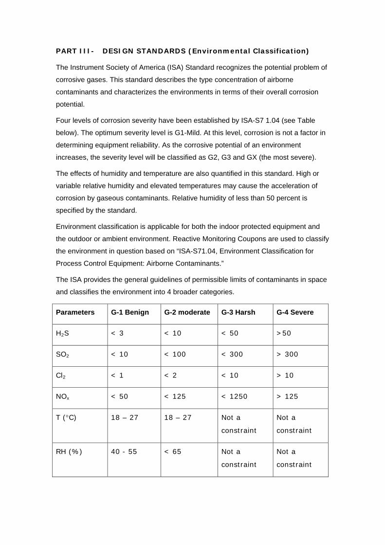
PART III- DESIGN STANDARDS (Environmental Classification)
The Instrument Society of America (ISA) Standard recognizes the potential problem of
corrosive gases. This standard describes the type concentration of airborne
contaminants and characterizes the environments in terms of their overall corrosion
potential.
Four levels of corrosion severity have been established by ISA-S7 1.04 (see Table
below). The optimum severity level is G1-Mild. At this level, corrosion is not a factor in
determining equipment reliability. As the corrosive potential of an environment
increases, the severity level will be classified as G2, G3 and GX (the most severe).
The effects of humidity and temperature are also quantified in this standard. High or
variable relative humidity and elevated temperatures may cause the acceleration of
corrosion by gaseous contaminants. Relative humidity of less than 50 percent is
specified by the standard.
Environment classification is applicable for both the indoor protected equipment and
the outdoor or ambient environment. Reactive Monitoring Coupons are used to classify
the environment in question based on “ISA-S71.04, Environment Classification for
Process Control Equipment: Airborne Contaminants.”
The ISA provides the general guidelines of permissible limits of contaminants in space
and classifies the environment into 4 broader categories.
Parameters G-1 Benign G-2 moderate G-3 Harsh G-4 Severe
H2S < 3 < 10 < 50 >50
SO2 < 10 < 100 < 300 > 300
Cl2 < 1 < 2 < 10 > 10
NOx < 50 < 125 < 1250 > 125
T (°C) 18 – 27 18 – 27 Not a
constraint
Not a
constraint
RH (%) 40 - 55 < 65 Not a
constraint
Not a
constraint

Benign G-1: An environment sufficiently well controlled so that corrosion is not a
factor in determining equipment reliability. These are locations where both temperature
and humidity is controlled with closer tolerances. (Typically for control rooms, rack
rooms, technical services and laboratories)
Moderate G-2: An environment in which the effects of corrosion are measurable and
will effect the equipment to various degrees. These are locations where air
temperature is controlled but relative humidity limits are little flexible of not exceeding
65%. (Typically for motor control rooms, switchgear rooms and electrical substations)
Harsh G-3: An environment defined so that only specifically designed and packaged
equipment would be expected to survive. This is typically of most ambient environment
in chemical facilities.
Severe G-4: Very harsh generally never a recommended option.
The process equipment manufacturers provide necessary information on the class
category their equipment is suited for and the filtration supplier provides the chemical
filtration equipment to achieve the classification demanded by the process equipment
supplier.
Higher the classification category of the process equipment, higher will be the
equipment cost and lowest is the cost of treatment.
Three (3) Steps identified for Corrosion Prevention
1) Environment Assessment
The Environmental Assessment is required to characterize the reactive potential of an
environment. As part of the assessment, ‘Environmental Reactivity Coupons’ (ERC)
are used to determine the types and levels of molecular contaminants present in the
air. This assessment strategy is a reliable and cost-effective to ascertain the type of
AMC control measures needed for the system.
By the use of “reactivity monitoring,” a quantitative measure of corrosion potential can
be established.
Reactivity monitoring involves placing strips of copper metal, called ‘corrosion
coupons’, in the areas of concern. The coupons are left exposed to environment for a
period of 30 days, and then analyzed for oxidation film and species of contaminants in
a qualified laboratory. The corrosion formation is measured in angstroms. This data is
used to determine the severity level of the environment that indicate the potential
damage that corrosive gases in the air could cause to electronic contacts.

2) Environment Control
Wide range of chemical filtration media is available for control of virtually any AMC
challenge. These media are the heart of the dry-chemical systems.
The new generation of filter media combines both the chemical and the particulate
filtration. The chemical media present in the filter can absorb the desired gasses.
Virtually all gasses such as ammonia, chlorine, methylamine, SOx, NOx, Ozone, HCl,
and HF could be adsorbed by chemical filtration. The composition of chemical media in
filtration is decided upon by the concentration of gasses present and that needs to be
removed. This is usually a patented design of suppliers.
An activated carbon filters such, as charcoal filters are suitable for removing VOCs and
other high molecular weight compounds. The disadvantage with this is that they are
highly imflammable.
3) Environment Monitoring
Environmental Reactivity Monitor (ERM) provides the continuous, real-time data
necessary to identify AMC and to verify the performance of chemical filters.
ERM usually consists of a quartz crystal sensor used to measure the mass
accumulation of the corrosive film that results from the reaction of contaminants with
the metals. The mass increase is described in terms of the corrosion film thickness
measured in Angstroms (Å). This highly sensitive method of measurement will indicate
the reactivity level of an environment with contaminant levels at or less than one part
per billion (1 ppb). The recorded readings classify the environment to
• Pure: Contamination does not pose a measurable threat to processes.
• Clean: Contamination is measurable, but does not pose an immediate threat to
processes.
• Moderate: Contamination is slightly above the levels considered acceptable for
processes.
• Harsh: Contamination is above the levels considered acceptable for processes
• Severe: Contamination poses an immediate threat to processes.

PART IV- HVAC DESIGN CONSIDERATIONS
The technical knowledge and equipment necessary to build controlled environments
that would meet the standards established by the Instrument Society of America (ISA)
on process control equipment’s shall require considerations to 4 vital considerations
on HVAC design.
1. Relative Humidity: To be less than 50% with close control of deviations no
greater than 6% per hour.
2. Temperature: To be maintained at the lowest level possible consistent with
personnel comfort, typically 72°F, 22°C (±2°F, ±1-2°C).
3. Gas-phase Purification: To maintain gas concentrations to levels acceptable
for a G-1Class environment as defined by the ISA (i.e., H2 S < 3ppb, SO2 < 10
ppb, NOx < 50 ppb).
4. Room Air Pressurization: To be 0.05”wg to 0.1”wg at a rate of 1 to 3 air
changes per hour (2-5% of gross room volume).
REMOVAL OF CORROSIVE GASSES (Air Purification)
The corrosive environments require special filtration in eliminating gaseous
contaminants in the fresh make up and/or re-circulating air streams.
The petroleum refinery for instance, using hydrocarbons to produce primary and
intermediate petrochemical materials, which are subsequently converted to plastics,
synthetic fibers, and synthetic rubber; typically release hydrogen sulfide (H2S), chlorine
(Cl2), sulfur dioxide (SO2), and nitric oxide (NO2) — all highly corrosive gases. These
gaseous contaminants in the air can create an atmosphere hostile to electronic/electric
equipment. Even quantities of a few parts per billion will have severe consequences.
Corrosion of contacts and components on circuit boards accounts for approximately
40% of all equipment failures in such industrial facilities.
Corrosive agents do not only come in the form of gaseous contaminants. Particulate
matter can be equally corrosive. Minute particles of airborne dust can settle upon
metallic portions of contact surfaces. If the dust is hygroscopic, i.e. water adsorbing; it
will be attracted to the metal surface and gets accumulated to form electrolyte films.
Non-hygroscopic dusts having high surface areas adsorb gaseous contaminants. This
too can actively contribute to corrosion by concentrating reactive contaminants on
contact surfaces.

Since the problem of corrosion is caused by the reaction of air borne impurities on
metals, proper design guidelines mandate the removal of all such contaminants from
the air stream. P & C projects, aware of the potential risks and costs associated with
inadequate corrosion control, made plans early on to incorporate chemical filtration
into the HVAC designs.
AIR FILTRATION
Airborne particles and debris are constantly drawn into the air intakes of HVAC units
impacting equipment performance. Proper air filtration made of the right materials is
therefore very challenging in corrosive or wet environments. To better understand and
appreciate the capabilities of air filtering systems, we must examine what
contamination needs to be cleaned. There are three types of airborne contaminants:
liquids, solids and gases.
The two most common techniques available to deal with low-level airborne
contamination are
1. Particle removal filtration, such as mechanical filters and electronic air
cleaners, and
2. Gas-phase (dry scrubbing) filtration
• Particulate filters vary in their ability to remove particulate matter,
depending upon the filter's material composition (typically cellulose, fabric,
non-woven cotton, synthetic blend and glass-fiber materials). Most
conventional air conditioning systems come with low- to mid-efficiency
filters. These are essentially provided to protect the internals of HVAC
equipment and are not meant for eliminating biological or chemical
contaminants. The efficiency of these filters is typically 20 to 65 percent.
• Electronic air cleaners, another form of particulate filtration, use the
principle of electrostatic precipitation. Particles are charged and then
captured on collecting plates. They are relatively efficient against particles
of sub-micron size, but require regular cleaning. The electronic air cleaners
consists of an ionizing section; alternatively spaced grounded struts &
charging ionizing wires and collecting section; alternatively grounded and
charged plates with insulators located out of air stream.
• High efficiency particulate air (HEPA) filtration is employed where
cleanliness requirements is very stringent. A 99.97% efficient HEPA filter is

designed to remove microbial and biological contaminants and can trap
particles down to 1-micron size.
• The standard engineering practices suggest:
Transfer fan (100% recirculation) systems should use pleated 25-30%
efficiency prefilters
System employing outside air and return air should have a minimum
efficiency of 95% (AHSRAE)
100% make up air systems to clean areas should have HEPA filters on
the fan discharge and 95% (ASHARE) bag filers on the inlet
The principle references for filter specifications and tests can be found in:
ANSI –N101.1 : “Efficiency testing of air cleaning systems containing devices for
removal of particles”
ANSI/UL 586 : “Test Performance of High Efficiency Particulate Air Filter Units”
ANSI/UL 900 : “Air Filter Units”
ASHRAE – 52.1 : “Method of Testing Air Cleaning Devices used in general
ventilation for removing particulate matter”
ASTM Part 46 : “Filtration”
ARI 850 : “Air Filtration….”
Gas-phase Filtration
Traditional particulate filters, found in most conventional HVAC systems remove dust
and dirt from the make up or re-circulation air.
And while HEPA filters shall trap biological contaminants or spores, these are
ineffective against chlorine gas, H2S and other corrosive gaseous contaminants.
Complete protection requires multiple stages of filtration.
Gas-phase air filtration employs adsorbent-impregnated media to remove chemical
gases from the air. Gaseous contaminants, both externally and internally generated,
can be effectively removed down to the low parts per billion levels through the process

of adsorption, and/or chemical reactions. Oftentimes, these systems are used in
tandem with particle removal filters or HEPA filters for complete protection.
Adsorption is the most common form of gas-phase filtration. The material most often
used is carbon (activated and/or impregnated charcoal). Carbon is a very effective
gas-filtration media specifically for volatile organic compounds (VOC) due to its high
porosity, large surface area presented to the airstreams and high removal capacity.
The standard engineering practices require 8.8 lb (4.0 kg) of activated carbon per
2000 CFM (944 L/s) of airflow or in extreme cases it may be 12 lb (5.4 kg) of activated
carbon per 500 CFM (236 L/s) of airflow.
Activated carbon, is often used in conjunction with activated alumina impregnated with
potassium permanganate filtration where called for assured occupant safety and to
protect vital processes. The other chemical filtration media composition may be
selected, which is dependent on the nature of the contaminant present in the vicinity.
Chemical filtration activated materials are usually manufacturer’s trademark and the
suppliers like ‘Purofil’ need to be consulted for appropriate filtration technology specific
to the industry.
Gas-phase filtration systems typically have gas removal efficiencies of 99.95 percent.
To reach this level of efficiency, a system may employ multiple media beds - taking
advantage of the strengths of the media to target specific gases. The outdoor/ambient
air classification is required to determine the type and filter bed thickness.
Dry Chemical Scrubbers
Dry Chemical Scrubbers (DBS) are utilized for areas exposed to very high levels of
gaseous contaminants. The scrubbers are available to deliver G1-class air (as defined
by the Instrument Society of America) and are typically suitable for any of the following
industries:
• Mining & Drilling Operations
• Refineries and Petrochemical Plants
• Pulp & Paper Mills
• Waste Water Treatment Facilities
• Heavy Manufacturing, Pharmaceutical & Chemical Plants
• Semiconductor & Photo Film Manufacturing
• Various Other Corrosive Environs Coastal & Marine

The DBS is constructed of corrosion-resistant materials, making it suitable for
installation outside of the space it is protecting. Systems are available from 700 CFM
and higher, and are often custom built for specific applications.
Advantages of the DBS include:
• Multiple media stages for broad-spectrum removal of gases
• Offers high-efficiency gas removal at a low cost per CFM.
• Flexible system designs make it easy to meet specific pressurization
requirements
Advanced designed DBS equipment comes with integral air monitor controller. The
controller verifies the cleanliness of the scrubbers’ discharge air, as well as the air
within the controlled space. The readings are displayed on real time basis to check the
performance of the system.
Determination of the bed-depth is dependent on:
• Indoor environment classification required
• Outdoor environment classification measured
• The gross volume of area to be protected
• Contaminant type for chemical media selection
The bed configurations can vary from one stage of 1.25” (30 mm) to 48” (1200 mm)
bed depths in modules. The commercially available equipment configurations include:
• High-density scrubber, deep bed hopper style, providing counter flow
• Deep bed Air System providing various media stages
• Air Purification Unit, thin bed 3” (75mm) design, providing various media stages
In addition to the equipment the dry scrubbing chemical systems protect production
personnel from toxic gas emissions. For instance, the production of silicon wafers in
semiconductor industry exposes personnel to hazardous gases, such as diborane,
silane and phosphine. Even in low concentrations, these gases are strong irritants to
the eyes, skin and lungs. Chronic exposure may pose serious health risks. Dry
scrubbing systems remove these gases from re-circulation air and ensure controlled
and safe work environment.

MAKE UP AIR AND BUILDING PRESSURIZATION
Typically many of the critical electronic room installations have their own dedicated air
conditioning systems. These are supposedly controlled environments. While this is
good design strategy, many of the installations rely purely on re-circulation system
without paying much attention to pressurization. Without pressurization, gaseous
contaminants can seep into these sensitive rooms through cracks in wall and ceiling
joints, cable and utility penetrations, and spaces above drop ceilings and below raised
floors.
Positive pressurization is the basis of assuring that uncontrolled and untreated air
does not infiltrate the protected area. The ambient air used to provide the positive
pressurization must be treated to ensure environment free of both the gases and
particulates. The recommended minimum amount of positive pressurization gradient is
0.03” to 0.05” (~0.75 to 1.25mm) water column for clean room applications. This would
normally equate to 3- 8% of gross room volume.
Optimizing the make up air requirement
Careful attention needs to be paid ‘not to’ over-pressurize the system.
With pressurization, the requirement for make up air and the treatment costs due to
cooling /dehumidifying and chemical filtration also increases. The cost of treating the
make up air shall be very high, particularly for the extreme ambient environment
conditions.
The amount of outside air required is a function of
• Equipment exhausts and exhaust through toilets/kitchen/pantry/battery rooms
etc.
• Leakage through pass through, conveyor openings, strip curtains, air locks,
door under cuts etc
• Duct leakage, wall and ceiling leakages
• Level of positive pressurization required
• ASHRAE 62 ventilation guidelines on indoor air quality
The HVAC design must optimize the use of make up air and shall minimize the
uncontrolled air leakages while maintaining the controlled ventilation.

Impact on Energy Use
Over pressurization is waste of energy that not only entails high capital costs but also
increases the operating costs. Just to give an idea, one-inch water gauge pressure is
equivalent to wind velocity of 4005 feet per minute (~45 miles/hr). Internally in a
building this is equivalent to 5.19-lb/sqft force on glazing.
The makeup air requirements depend on the level of positive pressure required in the
room. High positive pressure requirement require high makeup air quantities. With
higher pressurization the leakage velocity, leakage rates and the processing costs
shall also increase.
Leakage through the fixed openings should be restricted as much as possible. The
amount of expected leakage can be calculated from the following:
Leakage in CFM = (Room Positive Pressure) ½ x 4005
Assuming 0.05” wg,
Leakage = 0.223 x 4005
= 895 feet per minute
With a total of 2 square feet opening size
Leakage = 2 x 895 = 1800 CFM
Higher positive pressure of say 0.1” wg (2.5 mm) shall mean higher velocity pressure
of 1266 fpm (~6.4 m/s). The amount of leakage for 2 square feet opening shall be
2532 CFM an increase of 40%. Higher the velocity pressure higher shall be the ex-
filtration or the leakages.
Assuming an ASHARE design condition of 95°F DB/72°F WB (~35°C DB/22° C WB)
and room conditions of 72°F DB/60°F WB (~22°C DB/15.5°C WB); ~50% RH, the
enthalpy difference is 9.5 BTU/lb (~22 kJ/Kg) of air.
For 1800 CFM leakage: this corresponds to heat load of
= 1800 x 9.5 x 4.5
= 76950 BTU’s/hr or 6.4 TR
For 2532CFM leakage: this corresponds to heat load of
= 2532 x 9.5 x 4.5
= 108234 BTU’s/hr or 9.0 TR

Thus with extra pressurization; 9.0 -6.4 = 2.6 TR of additional refrigeration capacity
need to be provided. Plus all the downstream equipment such as air-handlers, filter
media, ducting & auxiliaries shall increase. This is an extra capital cost.
The recurring cost on energy shall be again of the order of 2.6 KWh @ 1KWh per TR
of cooling load. Plus the replacement of activated carbon/chemical filtration media of
higher size shall cost more.
In summary, the building positive pressure should be limited to 0.03” to 0.05” (~0.75 to
1.25mm). The high positive pressurization is inefficient and shall be considered only if
called for by the safety and loss prevention advises on critical areas.
Air tightness of building shell
Positive pressurization can be maintained only if the sealing integrity of the building is
maintained. The building should be air tight for low air leakage performance. There are
areas with in the facility that require negative exhausts such as toilets, pantry,
laboratory or battery room but these are controlled ventilation areas having fixed
amount of exhaust. Uncontrolled leakages areas in the building are door undercuts;
pass through, walls, ceilings and duct joints etc; that should be restricted as far as
possible.
Remember a slogan:
“Build tight –ventilate right”
The building shall be pressurized to 0.03” to 0.05” wg (0.75 to 1.25mm) to achieve low
capital costs, overall energy conservation and treatment costs on chemical filtration.
HVAC Equipment Protection
The following types of commercial equipment may be susceptible to corrosion:
• Rooftop Units
• Air-Cooled Chillers
• Air-Cooled Condensing Units
• Remote Air-Cooled Condensers with Make-Up Air-Handling Equipment
Environment corrosion is a major problem associated with all HVAC coils both indoor
(cooling) and outdoor (condensing). The issue arises due to several factors:

The condenser coil, which is always located outdoors is rapidly attacked in saline and
industrial environments. The cooling coils are always wet due to moisture
dehumidification running on the tube and fin surfaces. In fact the day the coils leave
the factory corrosion is taking place due to the different types of metal used in the coil
construction.
Corroded coils lead to rapid losses in capacity, reduced efficiency, and increased
energy consumption. In seaside locations especially, the operating performance of
unprotected condenser coils may decrease over 50% in a single year. Three most
common forms of coil corrosion are galvanic, pitting and formicary. These corrosive
processes can occur in as little as a few weeks after installation. More typically,
corrosion will begin appearing within a one- to four-year period.
Galvanic corrosion: When dissimilar metals are in contact in the presence of an
electrolyte, a reaction occurs. This reaction is known as galvanic corrosion. For
galvanic corrosion to occur there must be a metallic couple between two or more
dissimilar metals in the presence of an electrolyte. If any one of the factors is not
present, galvanic corrosion will not occur.
The standard coil is manufactured from copper tubes mechanically bonded to
aluminum fins and the fin pack is assembled with galvanized steel tube sheets and coil
case. This assembly has classic galvanic corrosion components with multi-metal
bonds between the fin-and-tube and tube-and-tube sheet bonds. Galvanic corrosion of
the unprotected coil begins at the bi-metallic couple between the copper tube and
aluminum fin. Because the aluminum is less noble than copper, the aluminum material
corrodes.
In cooling applications, condensate accumulates on the coil surfaces when
dehumidification occurs. Wet coil surfaces resulting from condensation in the
presence of a contaminated airstream will lead to galvanic corrosion if not properly
protected. The environment creates the electrolytes necessary for general and
localized corrosion of materials.
Pitting corrosion is typically caused by the presence of chlorides or fluorides, which
are abundant in marine and coastal environments. Chlorides are also found in
numerous items such as snow-melting crystals, toilet bowl/tile cleaners, dishwasher
detergents, fabric softeners, vinyl fabrics, carpeting, paint strippers, etc. Fluorides are
used in many municipal water treatment plants. Unlike formicary corrosion, pitting is

usually visible on the exterior of the copper tube with the naked eye. Pitting is caused
by an aggressive attack of negatively-charged chloride/fluoride ions carried to the
metal surface by condensate. The negative ions attack the oxide film the metal usually
uses to protect itself, essentially forming a corrosion driven battery that consumes the
copper. After pits have formed in the copper, they will progress through the thickness
of the copper tube until a pinhole is formed causing the coil to leak refrigerant.
Formicary corrosion is caused by organic acids such as acetic and formic acids.
Acetic acids are abundant in numerous household products such as adhesives,
paneling, particle board, silicone caulking, cleaning solvents, vinegar, foam insulation
and dozens of other commonly found products in the home or commercial/industrial
workplace. Formic acid can be found in cosmetics, disinfectants, tobacco and wood
smoke, latex paints, plywood, and dozens of other materials. The corrosion caused by
these substances is usually not visible to the naked eye, although black or blue-gray
deposits can sometimes be seen on the surface. Formicary corrosion can form a sub-
surface network of microscopic corroded tunnels within the tubing wall resembling ant
nest-type structures that are substantially larger than the surface pinholes above them.
Eventually one or more of these tunnels will progress to the surface of the copper and
form a pinhole which quickly results in coil leakage.
How to protect HVAC equipment?
• Elimination of the bi-metallic couple can eliminate galvanic corrosion. This can
be accomplished with an all-copper coil, which eliminates the presence of
dissimilar metals, one of the requirements for galvanic corrosion.
• Another way to prevent galvanic, pitting or formicary corrosion is by isolation
through a protective coating. The protective coating will create a barrier
between the metallic couple and the electrolyte, thereby eliminating the
electrolyte, one of the requirements for corrosion.
Coil Coating
Coil coating is a technique whereby the coil’s dissimilar metals are separated by a thin
layer of inert organic pre-coating material. As a result, the electrical connection
between the copper and aluminum is insulated and thus inhibits the galvanic action.
The coating also forms the barrier between the coil material and the ambient harsh
conditions.

When choosing a protective coating for condenser coils, the important points to
remember (in addition to corrosion resistance and complete coverage of the coil), are
that the coating should be thin, flexible, impact resistant, and UV resistant.
Thickness of coating: The thinner the coating, the better the heat transfer, while too
thick coatings can lead to diminished heat transfer and restricts airflow over the
condenser coil. As fin spacing on condenser coils gets denser, this becomes more
important. Some coatings are so thick that fin bridging occurs, severely restricting the
efficiency of a condensing unit.
Flexibility and impact resistance: A coating that is not flexible or impact resistant will
crack or flake when the coils get hit or bent during normal operating conditions. Once
any portion of uncoated metal is exposed, corrosion will form and begin to corrode the
underlying metal.
UV resistance: Any condenser coil that will be exposed to sunlight should have a
coating that is resistant to UV radiation. Several of the popular post-coats do not have
inherent UV resistance and offer polyurethane “topcoat” to prevent rapid deterioration
of their base coating. Polyurethane is UV resistant. “A negative aspect is that the extra
layer of polyurethane adds undesirable thickness to the coating.
Another factor applicable primarily to cooling coils is the coating’s hydrophobicity, or
how well it drains condensation off the coil, to create optimum heat transfer
capabilities. Ideally, water would drain quickly off of the coil to avoid reductions in
efficiency.
There are numerous types of coatings available, but the four basic ones prominent in
the HVAC industry are:
1. Polyurethanes
2. Epoxies
3. Fluoropolymers
4. Silanes
All four types of coatings offer differing degrees of advantages in terms of corrosion
resistance, scratch resistance, flexibility, weight, thickness, hydrophobicity, and heat
transfer capabilities. Each has its own strengths and weaknesses.

Polyurethane (PU) coatings are fairly inexpensive, less viscous, more flexible, and
thinner (typically 25 to 50 microns) than most coatings. The disadvantage is they are
not as resilient or long-lasting as other coatings.
Epoxy, or phenolic-based, coatings are generally the cheapest of available coatings.
These are known for their excellent chemical and heat resistance, and are well known
for coating floors and other surfaces. The high viscosity of epoxy-based systems leads
to thicker coatings (approximately 50 to 100 microns). Because they are thicker, epoxy
coatings will reduce heat transfer from the air to the refrigerant in the coil, and thus
cause a decrease in system efficiency and capacity. Epoxy coatings might best suit
new installations where heat transfer losses are accounted for in the system design
specifications.
Fluoropolymers (commonly known by trade name Teflon), are known for their high
resistance to acids, solvents and bases. They are most effectively applied to metal
through electrostatic powder coating or a thermal sintering process, as is done during
the manufacturing of cookware and other non-stick products. The field-use sprays
generally have very poor adhesion and their effectiveness will diminish significantly in
a very short period of time. The cost of fluoropolymer-based field-use coatings is
typically less than the more advanced epoxy and PU based coating system but their
lifetime and effectiveness is very limited.
Silanes are well known as excellent coupling agents where two dissimilar materials
exist. These form an extremely thin coating when cured (less than 10 microns) that
has very little, if any, adverse effects on heat transfer. They are very resilient against
cracking and corrosion, are hydrophobic, and reduce airflow friction. A variety of silane
chemistries are available, many of which are tailored to have particular characteristics
such as flexibility, hydrophobicity, and scratch resistance. Thus, the proper formulation
of a silane coating can provide a flexible, resilient glass-like coating with good
corrosion resistance and water draining capability that bonds extremely well to
aluminum and copper (an inorganic).
Studies indicate a silane-based coating provides the best protection from the
environment, and has minimal impact on heat transfer while retaining a long-lasting
barrier that protects a HVAC coil against corrosion for an extended period of time
(typically five years or more).

Coating Techniques
There are two general categories of protective coatings, pre-coats and post-coats.
Pre-coated Aluminum-Fin Coils
Pre-coat processes coat sheet aluminum before it is manufactured into coils. Pre-coats
are not a very good long-term coating solution because the manufactured edges are
not coated and are therefore exposed to corrosive forces. This results in a rapid
deterioration of the coil. In addition, the application of a pre-coat prior to manufacture
precludes the effective application of any other type of coating to the coil.”
The pre-coating offers protection in mildly corrosive coastal environments when
compared to standard uncoated coil, but is not recommended in severe industrial or
coastal environments.
Post-coated Aluminum-Fin Coils
There are two methods for applying post-coat coatings: dipping or spraying.
All coatings applied by a dip process must be applied at a factory. Products are
immersed into product baths a set number of times and for specific durations, then
either baked or allowed to cure naturally.
Spray processes can be done either at the factory or in the field. Field-applied
sprayed-on coatings generally do not provide sufficient protection in corrosive
environments. Possible reasons for poor performance:
• Coil cleanliness is crucial for proper adhesion. Adequate field cleaning
techniques are generally overlooked.
• Field application cannot ensure continuous coating of coil surfaces on multiple
row coils. Interior coil surfaces remain untreated.
• Inconsistent coating thickness minimizes coating protection. Recommended
coating thickness of 2.5 mils for standard units and 1 to 1.5 mils for units with
enhanced fins and high fin density cannot be ensured with field application on
multiple row coils. Film thickness measurements are generally overlooked.
• Coil must be void of corrosion prior to field application of the coating.
Encapsulation of existing corrosion makes the coating ineffective or can lead to
continued deterioration and coating delamination.

Electro-coating
The fundamental principle of electrocoating is that the materials with opposite
electrical charges attract each other. An electrocoating system applies a DC charge to
the coil immersed in a bath of oppositely charged epoxy molecules. The molecules are
drawn to the metal, forming an even, continuous film over the entire surface. At a
certain point, the coating film insulates the metal, stopping the attraction, and
preventing further coating deposition (self-limiting nature of the coating process).
This coating process creates a smooth, consistent, and flexible coating that penetrates
deep into all coil cavities and covers the entire coil assembly including the fin edges.
The process in conjunction with the coating material results in a less brittle, more
resilient, and more durable coating without bridging between adjacent fins. E-coated
coils provide superior protection in the most severe environments.
Performance Trade Offs
The purpose of any protective coating is to insulate the material being coated from the
environment. A potential disadvantage to coating condenser coils is that there may be
a negative effect on the performance of the condensing unit when compared to the
performance of the same unit with an uncoated coil. Consequently, there may be a bit
of a trade-off between performance and protection.
This trade-off can be limited by selecting a coating that either enhances the coil’s
ability to function, or that only affects it minimally.
If a coating is too thick, airflow over the coils will be restricted, affecting pressure drop.
Coatings that are too thick or that contain organic pigments may also inhibit thermal
transfer. The optimum coating is thin, so it does not significantly inhibit heat transfer.
Caution - When considering coated coils, it is important to also consider the effects of
moisture carryover. Moisture carryover occurs when accumulated condensation is
blown from the coil surface during cooling coil applications. The extent of carryover is
a function of airstream velocity across the coil, fin spacing, fin geometry and material
of construction. The coating increases the tendency of moisture carryover and to
prevent this, the coil should be selected for lower face velocities.

MAXIMUM RECOMMENDED FACE VELOCITY (FPM) Fin Spacing (FPI) Aluminium-Fin Copper-Fin Coated Coil
8 650 500 500 11 650 425 425 14 575 375 375
FPI – Fins per inch FPM – Feet per Minute
Alternatives to Coating (Copper-Finned Coils)
Copper-fin, copper tube coils eliminate the bimetallic bond found on standard coils.
Stainless steel tube sheets and coil cases further improve the corrosion durability of
the entire coil assembly. As a result, the potential for corrosion is reduced since
bimetallic couples can be minimized within the coil assembly.
Copper-fin coils are priced higher than aluminum pre-coated fin coils, since material
costs are greater than aluminum. However, coastal corrosion durability is substantially
improved over the standard or pre-coated coil construction, since the bi-metallic
construction is not present.
Note - Copper-fin coils provide increased corrosion resistance in harsh coastal
environments where industrial air pollution is NOT present. Copper is generally
resistant to coastal environments, since a natural protective film is formed to passivate
the copper surfaces and a mono-metal bond exists between the tube and fin. But the
use of uncoated copper coils is NOT appropriate for industrial applications, since many
industrial contaminants (like ammonia) attack copper. Post-coated aluminum-fin coils
should be considered for industrial applications.
Additional thoughts
HVAC equipment operating in corrosive environments needs special precautions.
• Strict control of temperature and humidity diminishes the impact of corrosion. In
addition, proper control instrumentation & logics, HVAC equipment protection,
indoor air quality codes and generally accepted practices must be addressed.
• Ensure HVAC air-handling equipment casings are fabricated from galvanized
sheet steel that is epoxy powder coated including all divider panels and motor
mountings. All bolts, screws and fittings shall be stainless steel. Where the
ambient environment is very harsh consider specifying all steel metal casings,
components and fittings in 316-grade stainless steel

• Ensure all external exposed equipment located outdoors is provided with
cathodic protection.
• As per ASHRAE Standard 62-1999, specify equipment with the slopped, non-
corrosive drain pans, cleanable surfaces and accessibility. Preferably use
stainless steel drip pan beneath the cooling coil.
• Locate equipment in a way that prevents exposure of equipment to the air
stream.
• Fans provide airflow and static pressure to cater for positive pressurization and
required ventilation air changes per hour. Fans are often exposed to toxic or
corrosive fumes laden environments. Consider stainless steel fan or fiber
reinforced plastic (FRP) assembly option. Designed for continuous operations
consider, galvanized housing with powder coat enamel. Consider
polypropylene axial fan assembly with alloy hub non-sparking type for
condenser unit fans located outdoors in harsh environments.
• Provide service access on both sides and front of the unit by means of
removable covers to give full access to all major components.
• In dealing with the corrosive environments, plant may be required to operate
within an area where an explosive atmosphere may occur. Special precautions
must be undertaken to ensure that the HVAC equipment itself does not provide
a possible source of ignition to the atmosphere present. Electrically, provide fan
motors that are certified flameproof for zone 1 operation.

Course Summary
Saline coastal environment, large processing facilities (like refinery, P&C plants,
fertilizers, treatment facilities etc.), heavy industrial production areas (metal & mining,
paper & pulp etc), auto emissions and power generation facilities release variety of by
products and contaminants that cause corrosion. The control rooms, data centers,
telecom areas and other sensitive facilities operating under such diverse and harsh
industrial environments require special HVAC attention against corrosion.
To ensure that the services operate as they are intended, corrosion control is essential
element of HVAC design. Controlling contaminants by reducing their concentration to
acceptable levels and/or eliminating them from the air stream is key to corrosion
control. Effective corrosion control also requires maintaining precise indoor
temperature and humidity in narrow tolerances. Elevated humidity and temperature
increases the intensity of corrosion. The indoor relative humidity (RH) shall not be
allowed to exceed 50%.
Chemical filtration helps in removal of odorous, toxic, and corrosive gases through
adsorption process.
Heavy industry plants, mills and refineries rely on dry scrubbing systems to protect
process and motor control systems from the damaging effects of corrosion.
Inadequate environmental protection may result in manufacturer’s limiting warranties
on the equipments, the cost of which has to be borne by the end-user alone.
Corrosion control must be seen as a vital activity to enhance energy efficiency,
productivity and equipment life. Remember whereas the equipment design issues
rests with the manufacturers, ensuring a satisfactory environment is sole responsibility
of the end user.
********