hvdc ppt by sanjeev
TRANSCRIPT

RECENT TRENDS IN HVDC TRANSMISSION
P.V.S.Sai kumar M.V.Satyanarayana
REGENCY INSTITUTE OF TECHNOLOGY,YANAM.
ABSTRACT
During the latest 20 years,
HVDC has become the dominating
technology for long distance transmission of
bulk power. The use of 800 kV HVAC that
was introduced in several countries during
the 1960´s and 1970´s has come to a halt .
Therapid development and the increased
confidence in the HVDC technology have
caused the transition from ac to dc. This
paper will cover the classic thyristor based
HVDC technology. The newer HVDC Light
technique will be covered in a companion
paper.
Keywords: AC filters, Capacitor
Commutated Converter,Control systems,
DC filters, Development, Garabi, HVDC
converters, HVDC systems, Power
transmission, Thyristor valves
Introduction:
Worldwide there is an increasing interest in
the application of HVDC at voltage levels
above what is presently used. The main
reason is that most of the hydro power
resources that are within convenient distance
to the consumer centers have been exploited
by now, and in order to meet the increasing
demand for clean, renewable energy, remote
hydro generation plants are built. This asks
for efficient means for long distance, bulk
power transmission, a typical scenario is
6000 MW to be transmitted 2000-3000 km.
esources that are within convenient distance
to the consumer centers have been exploited
by now, and in order to meet the increasing
demand for clean, renewable energy, remote
hydro generation plants are built. This asks
for efficient means for long distance, bulk
power transmission, a typical scenario is
6000 MW to be transmitted 2000-3000 km.
hydro generation plants are built. This asks
for efficient means for long distance, bulk
power transmission, a typical scenario is
6000 MW to be transmitted 2000-3000 km.
esources that are within convenient distance
to the consumer centers have been exploited
by now, and in order to meet the increasing
demand for clean, renewable energy, remote
hydro generation plants are built. This asks
for efficient means for long distance, bulk
power transmission, a typical scenario is
6000 MW to be transmitted 2000-3000 km.
Also in countries like China and India with
vast coal resources, a certain quota of hydro
power is needed for stabilizing purposes.In
China large hydropower resources are
available in the Western part of the country
and the power will be transmitted to the
industrialized regions in the Eastern and
Southern areas of China In India transfer of
the hydropower generated at the Bramaputra
River Basin in the North-Eastern part of
India will have to be transmitted to the
southern part of the country where the
power is needed. In Africa there is a great
potential for power production at the basin
of the Congo River near the location of
Inga.Parts of the power is planned to be
transmitted to South Africa.
In Brazil vast hydropower resources are
located in the Amazon region, while the
power consumer centers are located along
the eastern coast.In several investigations
that have been carried out in the past, the
common conclusion has been that for these
big amounts of power and long distances the
use of 800 Kv HVDC is the most
economical solution. [1], [2].The realization
of an 800 kV HVDC system is of course a
matter of insulation. Most of the equipment
will not be affected, see figure 1, and
equipment for lower voltages is often built
up by modules with resistive and capacitive
voltage grading that can be extrapolated to
higher voltages by adding more modules.In
order to meet the requirements from the
market, ABB is at present working with
development of equipment for 800 kV
HVDC.
The development of HVDC systems in the
last 10 years has three main avenues
compared with the technology of 1990:
1. The traditional classic HVDC technology
is still dominating but with improved
equipment and sub-systems (e.g. valves, dc-
bushings, AC-filters, DC-filters etc.)
2. The new circuit concept of CCC
(capacitor commutated converter) in the
classic HVDC technology, that significantly
improves the performance of the traditional
converter.
3. The new HVDC using VSC (voltage
source converters) using IGBTs in place of
thyristors.In all of the three lines of
development the industry has taken
maximum benefit of the dramatic
development that is taking part in the part in
the computer field.Today’s development is
to a significant extent directed to the VSC
technology (in the ABB case the HVDC
Light) that presently is developed in the
lower power range (below ≈300 MW),
where it has found many interesting
transmission uses besides the traditional
HVDC applications. It is believed that VSC
systems such as HVDC Light in a few years
will take over a large portion of the
traditional HVDC market, that presently
covered by thyristor technology. The use of
Ultra High Voltage Direct Current
(UHVDC), i.e. voltages above the highest in
use, 600 kV,has been found to be
economically attractive for power blocks up
to 6000 MW for distances above 1000
km,Furthermore the use of 800 kV as
transmission voltage will be achievable
within the near future with a limited amount
of development work. None of the AC
equipment, auxiliary equipment or control
and protection will be affected by the
increase of DC voltage. Also most of the DC
equipment is easily modified for 800 kV,
such as thyristor valves and DC filter
capacitors. Station external insulation and
line insulation must be carefully
considered. In order to meet the demands,
ABB has started an R&D program with the
goal to develop and test equipment needed
for 800 kV HVDC.
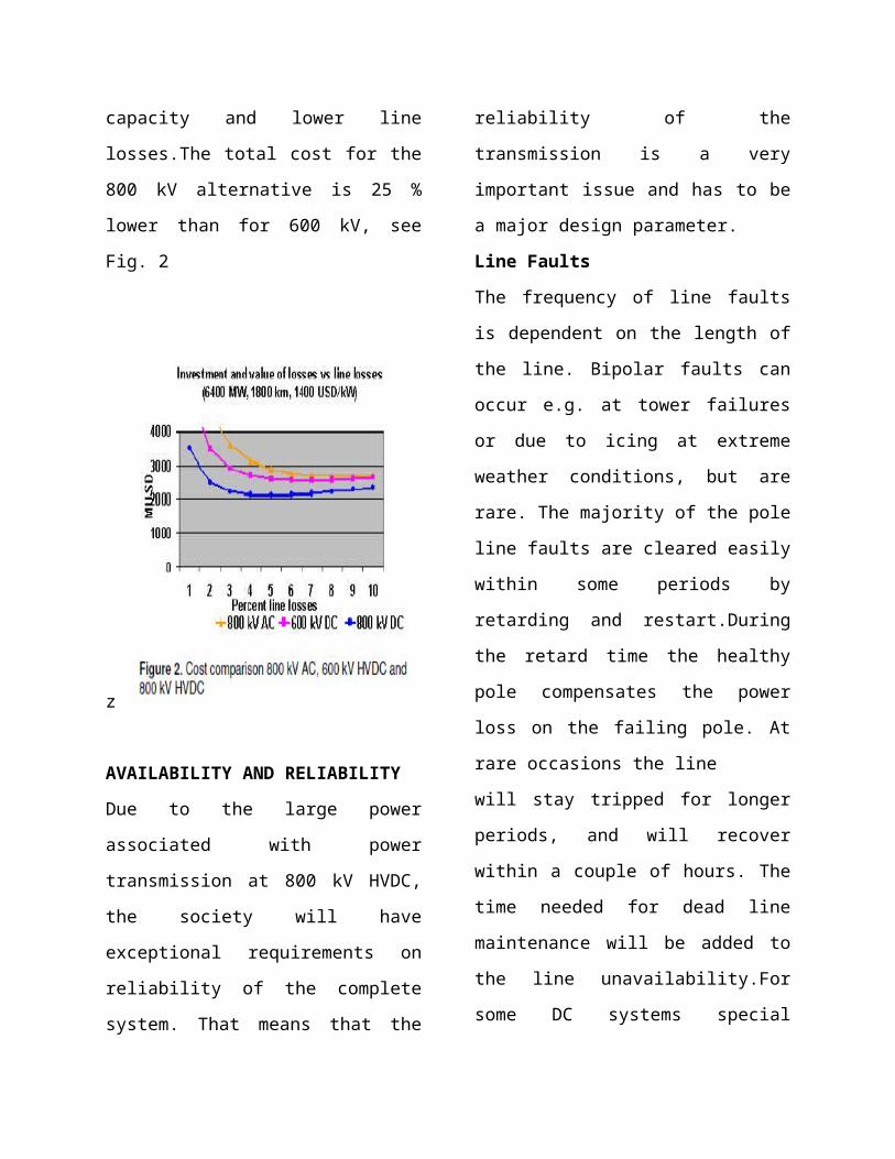
ECONOMY

The total cost for a HVDC transmission
system is composed of the investment in
converter stations and line and the
capitalized value of the losses. For a given
power the cost for the stations increases with
the voltage,while the line has a minimum
combined cost at a certain
voltage.A comparison of the total cost for
transmitting 6400 MW over 1800 km at 800
kV AC, 800 kV DC and 600 kV DC has
been done. 1400 USD/kW has been applied
when
calculating the value of the losses. The result
is that the800 kV DC is the most cost
effective alternative depending on a higher
line capacity and lower line losses.The total
cost for the 800 kV alternative is 25 % lower
than for 600 kV, see Fig. 2
z
AVAILABILITY AND RELIABILITY
Due to the large power associated with
power transmission at 800 kV HVDC, the
society will have exceptional requirements
on reliability of the complete system. That
means that the reliability of the transmission
is a very important issue and has to be a
major design parameter.
Line Faults
The frequency of line faults is dependent on
the length of the line. Bipolar faults can
occur e.g. at tower failures or due to icing at
extreme weather conditions, but are rare.
The majority of the pole line faults are
cleared easily within some periods by
retarding and restart.During the retard time
the healthy pole compensates the power loss
on the failing pole. At rare occasions the line

will stay tripped for longer periods, and will
recover within a couple of hours. The time
needed for dead line maintenance will be
added to the line unavailability.For some
DC systems special arrangements have been
done to increase the power availability. In
the Inga-Shaba
HVDC project, the two converters in the
bipole can be paralleled and the power can
be transmitted on one pole line, however at
higher losses. Switching stations along
the line allows for simultaneous line faults
on different segments along the line. For the
Itaipú HVDC project, with two bipoles in
parallel, the two converters can be
connected in parallel to one bipole, in order
to minimize the loss of power at bipole line
outage.
Converter Stations
The structure of the present control and
protection system, cable routing and
auxiliary systems should be revised,
reflecting the different requirements
onreliability and availability and also the
new configuration.It is envisaged that the
two poles will be totally independent and
that the groups in each pole will have a
minimum of interactions. Ideally, the bipole
should be built as two separate monoples.
This should also be applied for the AC-yard
configuration, with possibility to entirely
disconnect the areas that are needed for each
separate pole.Each twelve pulse group will
have a separate valve hall with six double
valves and six single phase two winding
transformers penetrating into the hall, i.e.
the same arrangement as for the recent ± 500
kV, 3000 MW projects.
CONVERTER CONFIGURATION
The rating of the transmission, 6400 MW,
makes it necessary to have more than one
converter group per pole. This will minimize
the disturbances at faults and increase the
reliability and availability of the
transmission. Another reason for dividing
into more groups is the transport restrictions
(size and weight) of the converter
transformers. A scheme with more than one
group per pole is not new, in fact it was used
in the mercury arc valve projects from the
mid 60’s where six pulse groups were
connected in series to achieve the desired
voltage. Each group had a by-pass
breaker,should one mercury arc valve be out
of order. The Itaipu ± 600 kV HVDC project
is the only project with thyristor valves that
has two groups per pole and the operation
experience is excellent.The arrangement on
the DC-yard will be almost the same
as for the ± 500 kV projects but with all
equipment rated for ± 800 kV. The only
“new” equipment is the by-pass arrangement
with disconnectors and high-speed
breakersfor each group,
INSULATION COORDINATION
General
For 800kVDC stations, the basic ideas for
insulation coordination are the same as those
applied for lowervoltages; i.e. to have
equipment with withstand characteristics
above the expected stresses. Then, as is
normal in medium or high voltage, the
expected stresses are controlled by a
combination of arresters and shielding. The
difference for 800kVDC is that it is
economically beneficial to control the
expected stresses to an even higher degree,
and to revise the steps leading from the
expected stresses to the desirable insulation
withstand; i.e. the insulation margins.One
has to remember that both aspects aim at
improving the economy of a given system.
Too loose control resultsin costly
equipment, and too tight control results in
costly arrester schemes and shielding.
Regarding margins,a similar situation
appears: too small margins result in costly
equipment failures, too large margins result
in costly equipment. There is a human factor
in the latter aspect, though: Adding margins
may save some engineering costs. For
800kVDC, mainly due to the high non-
linearity in the relationship between
withstand and
necessary clearances, the savings in
engineering are far outweighed by the
savings in equipment by a judicious choice
and application of margins.
Case Study
An insulation coordination study has been
performed for the dc side of an 800kV
HVDC transmission system. The data for
the system has been assumed based on the
best available estimates to the authors
colleagues, with regard to preliminary
design of the equipment expected for such
an installation. Further, as the study
progresses, it became apparent that one fine
adjustments to the configuration would yield
significant benefits: Splitting the smoothing
reactor function in two equal
inductances,one at the neutral, and one at the
pole.
Protection Scheme (Controlling the
Stresses)

In addition to the use of modern, highly
effective arresters permitting very good
ratios between steady state voltage and
protective levels, the protection scheme
arrived at included more arresters than are
usually applied at HVDC schemes of, e.g.
500kVDC. The reason
is that even relatively small gains in stresses
result in significant savings in equipment.
The arresters beyond the “usual” ones were
located to directly protect:· Valve side of
converter transformers at the uppermost 6-
pulse bridge · 800kVDC bus outside the
upper smoothing
reactor protected with several arresters at
specific locations on the bus · Smoothing
reactor on pole side · 800kVDC bus on
valve side of smoothing reactor The cost to
benefit ratio of this arrester proved to be
sensitive to station design parameters, and
its use will have to be decided on a case-by-
case basis.
Another important aspect comes from the
mentioned splitting of the smoothing
reactor. By balancing the inductance it is
possible to reduce the ripple appearing on
the arresters in the upper 12-pulse group,
making it possible to lower their protective
level.The third aspect is that controlling the
incoming lightning surges is also profitable.
Apart from the normal shielding at the
station, it is important to optimize the line
design for the towers nearest the converter
stations.Still another aspect is the locations
of arresters close enough to the protected
equipment, so that distance effects will be
negligible. The combination of this principle
with the natural distances between different
pieces of equipment in an 800kVDC station
leads to more arresters, even at the same
bus, and for the same protective levels.
Insulation Margins (Deriving Withstand
from Stress)
At the resulting stresses for 800kVDC
equipment it is extremely important to have
safety and economy dictated margins. There
is no room for additional margins based on
subjective appreciations.Perhaps even more
important: there is no rationale for
increasing calculated withstand levels to
“the next higher standard level”, since there
is no interchangeability of
equipment between different stations as is
normal for ac equipment.At lower voltages,
where high engineering and testing costs
cannot be justified, a simplification is often
applied
by forcing a ratio between the insulation
withstands to switching and lightning
surges. At the levels necessary for
equipment at 800kVDC, the voltage stresses
for all kinds of phenomena and transients

are carefully calculated. So are the internal
stresses for equipment designed to withstand
them, and so are the tests that verify them.
At UHVDC, the equipment should be
designed to withstand the actual stresses.
Then,depending on the materials, and the
internal
configuration of parts of different
resistivities and dielectric permitivities, the
ratio between withstand capabilities may or
may not be close to the traditional factors.
Therefore such relationship factors have no
reason to exist in 800kVDC insulation
coordination.They increase the cost of
equipment; yet only give a false sense of
security.Another reasoning taken slightly
out of context leads to insulation margin
levels that are not quite
justified.Specifically, for thyristor valves, by
extension, the same insulation margins used
for conventional equipment have
been required in some HVDC transmissions.
There are a couple of important points why
the same margins need not be used in the
thyristors, and not in the grading circuits.
One point is the extremely well controlled
voltage grading along the valve, transiently,
dynamically,
and even as a function of time after
application of a dc field, and even as the
years pass. Also the ambient conditions are
well controlled. This is also different from
conventional equipment. Because of the
above, the insulation margins for the
thyristor valves need not cope with the same
uncertainties as for, e.g. outdoor equipment.
EXTERNAL INSULATION
General
The study of external insulation is
considered as one key topic for the research
program related to 800 kV HVDC [3], for
the transmission line as well as for the
converter equipment. The research project
on the external insulation for 800 kV was
awarded to STRI in 1992 by ABB. A large
numbers of experiments were performed in
STRI’s laboratory with pollution test ability
up to 1200 kV DC. Some of the outcomes of
these studies were published successively
since 1993 on various international
conferences [4]-[8]. As a result of the
combined efforts on evaluating existing
converter stations, performing laboratory
tests and technical achievements on
equipment, design rules for HVDC
insulators has been established up to 800
kV.
Operational Experience
ABB has performed a review on the
operational experience of the existing
HVDC stations worldwide. . The operational
experience from existing HVDC stations,
from 250 to 600 kV, has shown that
theflashover rate of these stations has no
direct correlations to the voltage levels of
the stations. It has also shown that there is
no tendency and need to choose a higher
value for the specific creepage distance
because of higher voltage level. With
suitable design, a very low
flashover rate of 0.05 per pole per year has
been achieved in total 80 poles (47 stations)
around the world supplied by ABB. Good
operational experiences with silicone rubber
insulators, even with shorter creepage
distance than that of porcelain, have also
been obtained.
Site Conditions
The most important factor for the design of
external insulation is the actual site
conditions, as well as what is expected for
the future since the specific creepage
distance will mainly be decided by the site
pollution severity. Also factors such as site
altitude must be known
to allow for proper atmospheric corrections.
It is therefore very important to map the
pollution at a future HVDC site. In order to
make this possible, ABB can provide a
portable test station that measures airborne
pollution, collects weather data like wind,
rain, humidity and temperature. Also high
DC voltage (100 kV) is generated to
energize insulators to be set up at the test
station, to measure the pollution gathered by
the energized insulators. Also the leakage
current is
continuously measured for each individual
insulator. In a joint research activity
between BDCC of SGC, EPRI and ABB,
this portable test station has been utilized in
site pollution measurements for Three
Gorges-Shanghai projects. The
measurements performed on Huangdo and
Guojiagang sites will be presented in a
separate publication .
Laboratory Tests
Laboratory tests with pollution and with
uneven rain have been performed on
different type of insulators.Insulators of
different shed profiles have also been
compared in laboratory tests. It is also clear
from laboratory studies that for a SDD level
equal to or higher then 0.05mg/cm2, a linear
relationship holds between the required
creepage distance and the applied voltage
for
the same type of insulator. This fact
simplifies the dimensioning of the
insulation, when the pollution level is
known. The effects of various palliative
methods, such as hydrophobic coatings and
booster sheds have not only been reviewed
in the operational experience but also
verified in the laboratory tests.
Other Considerations
The most effective way to reduce the risk for
flashovers in the converter station is of
course to reduce the number of insulators.
The state of the art is to have the converter
transformer bushings protruding into the
valve hall, thus reducing the number of wall
bushing. Also the old type
of direct current transducers has been
replaced with optical current transducers in
modern converter stations.When possible,
composite silicone rubber insulators,with
superior surface properties, are used. The
ultimate solution of the external insulation
complex is of course to
build an indoor DC yard, as has been done at
Zhengping converter station. This should be
considered at sites with high pollution.
HVDC TRANSMISSIONS :POWER
CONVERSIONS APPLICATIONS IN
POWER SYSTEMS
need for more secure power grids and
growing environmental concerns continue to
drive the global deployment of HVDC
technology. HVDC is characterized by
numerous advantages; lower overall costs; a
smaller environmental footprint; easier
integration with alternative energy sources;
and above all, higher transmission stability
and power quality. Although over 50 years
old, the technology continues to rapidly
evolve. To address the pressing need for an
up-to-date, A-to-Z treatment of the subject,
Drs. Kim and Sood have collaborated on this
key textbook and professional reference.
The work combines classroom-tested
materials from both Kim and Sood,
compactly summarizes the latest research
results, and includes the insights of experts
from power electronics, control, and
simulation backgrounds. The authors walk
readers through basic theory and practical
applications, while also providing the
broader historical context and future
development of HVDC technology.

To address the pressing need for an up-to-
date, A-to-Z treatment of the subject, Drs.
Kim and Sood have collaborated on this key
textbook and professional reference. The
work combines classroom-tested materials
from both Kim and Sood, compactly
summarizes the latest research results, and
includes the insights of experts from power
electronics, control, and simulation
backgrounds. The authors walk readers
through basic theory and practical
applications, while also providing the
broader historical context and future
development of HVDC technology.
- Presents case studies covering basic and
advanced HVDC deployments headed by
world-renowned experts
- Demonstrates how to design, analyze and
maintain HVDC systems in the field
- Provides updates on new HVDC
technologies, such as active power filters,
PWM, VSC, and 800 KV systems
- Rounds out readers' understanding with
chapters dedicated to the key areas of
simulation and main circuit design
- Introduces wind power system
interconnection with HVDC
- Arms readers with an understanding of
future HVDC trends
HVDC is a critical solution to several major
problems encountered when trying to
maintain systemic links and quality in large-
scale renewable energy environments.
HDVC can resolve a number of issues,
including voltage stability of AC power
networks, reducing fault current, and
optimal management of electric power,

ensuring the technology will play an
increasingly important role in the electric
power industry.
To address the pressing need for an up-to-
date and comprehensive treatment of the
subject, Kim, Sood, Jang, Lim and Lee have
collaborated to produce this key text and
reference. Combining classroom-tested
materials from North America and Asia,
HVDC Transmission compactly summarizes
the latest research results, and includes the
insights of experts from power systems,
power electronics, and simulation
backgrounds. The authors walk readers
through basic theory and practical
applications, while also providing the
broader historical context and future
development of HVDC technology.
Balancing theoretical instruction with
practical application, HVDC Transmission
delivers comprehensive working knowledge
to power utility engineers, power
transmission researchers, and advanced
undergraduates and postgraduates in power
engineering programs. The book is also a
useful reference to for engineers and
students focused on closely related areas
such as renewable energy and power system
planning.
Siemens AG and its Indian arm Siemens Ltd
have won an order from Adani Power Ltd to
construct India's longest private high voltage
direct current (HVDC) transmission line.
The bipolar 500kV line will traverse 1,000
km from Mundra in Gujarat to
Mohindergarh in Haryana. Siemens and its
Indian outfit, apart from constructing the
line, will also build the HVDC terminal
stations at the two extremities, apart from all
supporting infrastructure en route. Phase-I of
the project is scheduled to commission by
February 2011 and the second, in July that
year. The order is valued at around Rs 1,500
crore.
The line will transmit power from Adani
Power's upcoming 4,620-mw coal-fired
power plant in Gujarat to Haryana. In
August last year, APL had entered into a
power purchase agreement with Haryana
Power Generation Corporation Ltd to sell
1,424 mw worth of power, for which the
Mundra-Mohindergarh line is being built.
Another 2,000 mw will be sold to Gujarat
through the 413-km dedicated 400kV line
from Mundra to Dehgam.
Meanwhile, the 4,620-mw Mundra power
plant is likely to see its first unit (of 330
mw) commissioning by June. The boiler
light-up took place on March 25.
Incidentally, Adani Power Ltd is also
developing a 1,980-mw coal-fired power
plant at Tiroda in Maharashtra. Adani will
sell 1,320 mw from the under-construction
Tiroda plant to Maharashtra. These two
projects, aggregating 6,600 mw, form the
bulk of Adani Power's goal of achieving a
power portfolio of 9,900 mw. The remaining
3,300 mw will come from two proposed
plants at Dahej in Gujarat and Kawai in
Rajasthan.
The WIN-TDC Control and Protection
System plays an important role in the
successful implementation of HVDC
transmission systems. High reliability is
guaranteed with a redundant and fault
tolerant design. Flexibility (through choice
of optional control centres) and high
dynamic performance were the prerequisites
for the development of our control and
protection system. Knowledge gained from
over 30 years of operational experience and
parallel use of similar technology in related
fields has been built into the sophisticated
technology we can offer today.
Main objectives for the implementation of
the HVDC control system are reliable
energy transmission which operates highly
efficient and flexible energy flow that
responds to sudden changes in demand thus
contributing to network stability.
All WIN-TDC components from the Human
Machine Interface (HMI) workstations, the
control and protection systems down to the
state of the art measuring equipment for DC
current and voltage quantities have been
upgraded to take advantage of the latest
software and hardware developments. These
control and protection systems are based on
standard products with a product life cycle
for the next 25 years.
The control is divided into the following
hierarchical levels:
Operator control level (WIN CC)
Control and protection level (Simatic TDC)
Field level (I/Os, time tagging, interlocking)
800 kV HVDC is economically attractive for
bulk power transmission, 6000 MW, over
long distances, 2000-2500 km. With the
present experience of HVDC as a sound
base, it is possible to realize an HVDC
system for 800 kV with reasonable efforts in
R&D by using building blocks that have
been used for lower voltages. With proper
separation and proper structure of the
control and protection and auxiliary systems,
the reliability and availability will be as
good as, or even better than, for converters
at lower voltage.

REFERENCES
[1] HVDC Converter Stations for Voltages
Above 600 kV,EPRI EL-3892, Project
2115-4, Final report February 1985
[2] HVDC Converter Stations for Voltages
Above ±600 kV, Cigré Working Group
14.32, December 2002
[3] P.C.S. Krishnayya, P.J. Lambeth, P.S.
Maruvada, N.G.Trinh, G. Desilets, S.L.
Nilsson, “An evaluation of the R& D
requirements for developing HVDC
converter stations for voltages above ±600
kV”, CIGRÉ 1988 Session, 14-01.
[4] W. Lampe, D. Wu, “Dimensioning
outdoor insulation for ±800 kV
transmission”, CIGRÉ SC 33
Colloquium,2.9, New Delhi, Sept. 1 to 2,
1993
[5] D. Wu, R. Hartings, U Åström,
”Investigations on the outdoor insulation of
±800 kV DC transmission
systems”,Proceedings of the international
Conference on Power System Technology,