hx system - montana satellite services revision b july 7, 2011 hx system hx200 satellite router...
TRANSCRIPT

1038054-0001Revision BJuly 7, 2011
HX System
HX200 Satellite Router Installation Guide
Copyright © 2008, 2011 Hughes Network Systems, LLC
All rights reserved. This publication and its contents are proprietary to Hughes Network Systems, LLC. No part of this publication may be reproduced in any form or by any means without the written permission of Hughes Network Systems, LLC, 11717 Exploration Lane, Germantown, Maryland 20876.
Hughes Network Systems, LLC has made every effort to ensure the correctness and completeness of the material in this document. Hughes Network Systems, LLC shall not be liable for errors contained herein. The information in this document is subject to change without notice. Hughes Network Systems, LLC makes no warranty of any kind with regard to this material, including, but not limited to, the implied warranties of merchantability and fitness for a particular purpose.
Trademarks
Hughes and Hughes Network Systems are trademarks of Hughes Network Systems, LLC. All other trademarks are the property of their respective owners. This product is compatible with the Hughes SPACEWAY system.
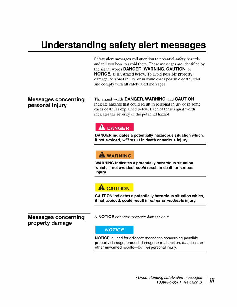
Understanding safety alert messages Safety alert messages call attention to potential safety hazards and tell you how to avoid them. These messages are identified by the signal words DANGER, WARNING, CAUTION, or NOTICE, as illustrated below. To avoid possible property damage, personal injury, or in some cases possible death, read and comply with all safety alert messages.
Messages concerning personal injury
The signal words DANGER, WARNING, and CAUTION indicate hazards that could result in personal injury or in some cases death, as explained below. Each of these signal words indicates the severity of the potential hazard.
Messages concerning property damage
A NOTICE concerns property damage only.
DANGERDANGER indicates a potentially hazardous situation which, if not avoided, will result in death or serious injury.
WARNINGWARNING indicates a potentially hazardous situation which, if not avoided, could result in death or serious injury.
CAUTION
CAUTION indicates a potentially hazardous situation which, if not avoided, could result in minor or moderate injury.
NOTICE
NOTICE is used for advisory messages concerning possible property damage, product damage or malfunction, data loss, or other unwanted results—but not personal injury.
• Understanding safety alert messages 1038054-0001 Revision B iii

iv
Safety symbols The generic safety alert symbol
calls attention to a potential personal injury hazard. It appears next to the DANGER, WARNING, and CAUTION signal words as part of the signal word label. Other symbols may appear next to DANGER, WARNING, or CAUTION to indicate a specific type of hazard (for example, fire or electric shock). If other hazard symbols are used in this document they are identified in this section.
• Understanding safety alert messages 1038054-0001 Revision B

Contents
Understanding safety alert messages . . . . . . . . . . . . . . . iiiMessages concerning personal injury. . . . . . . . . . . . . . . . . . . . . iiiMessages concerning property damage . . . . . . . . . . . . . . . . . . . iiiSafety symbols . . . . . . . . . . . . . . . . . . . . . . . . . . . . . . . . . . . . . . iv
Chapter 1Introduction . . . . . . . . . . . . . . . . . . . . . . . . . . . . . . . . . . . .1Scope and audience . . . . . . . . . . . . . . . . . . . . . . . . . . . . . . . . . . .1HX200 satellite router overview . . . . . . . . . . . . . . . . . . . . . . . . .1
HX200 for stabilized platforms . . . . . . . . . . . . . . . . . . . . . . . .2HX200 features. . . . . . . . . . . . . . . . . . . . . . . . . . . . . . . . . . . . . . .2
Transmission types . . . . . . . . . . . . . . . . . . . . . . . . . . . . . . . . . .3DVB-S2 compliant outroute. . . . . . . . . . . . . . . . . . . . . . . . . . .4Mobility . . . . . . . . . . . . . . . . . . . . . . . . . . . . . . . . . . . . . . . . . .4Signal and data interfaces. . . . . . . . . . . . . . . . . . . . . . . . . . . . .4
HX200 specifications . . . . . . . . . . . . . . . . . . . . . . . . . . . . . . . . . .5Physical, satellite, and mechanical specifications . . . . . . . . . .5Transmitter and receiver specifications . . . . . . . . . . . . . . . . . .6DVB-S2 compliant outroute rates and ratios . . . . . . . . . . . . . .7
Installation and commissioning . . . . . . . . . . . . . . . . . . . . . . . . . .7Contact information . . . . . . . . . . . . . . . . . . . . . . . . . . . . . . . . . . .8
Chapter 2Assembling and connecting HX200 hardware . . . . . . .11Preparing for the installation . . . . . . . . . . . . . . . . . . . . . . . . . . .11
Items required for installation . . . . . . . . . . . . . . . . . . . . . . . .11Items required for stabilized platforms. . . . . . . . . . . . . . . . . .11
Seatel antenna . . . . . . . . . . . . . . . . . . . . . . . . . . . . . . . . . . .11Azimuth antenna. . . . . . . . . . . . . . . . . . . . . . . . . . . . . . . . .11
Confirming installer laptop and site requirements . . . . . . . . .12Installer laptop requirements . . . . . . . . . . . . . . . . . . . . . . .12Remote site requirements . . . . . . . . . . . . . . . . . . . . . . . . . .12
Conducting the site survey . . . . . . . . . . . . . . . . . . . . . . . . . . .13Connecting the receive and transmit cables . . . . . . . . . . . . . . . .13
Connecting radio cables . . . . . . . . . . . . . . . . . . . . . . . . . . . . .13Connecting the Ethernet and power cables . . . . . . . . . . . . . . . .14Serial port interface connections . . . . . . . . . . . . . . . . . . . . . . . .15Connecting the hardware for stabilized platforms . . . . . . . . . . .16
• Contents 1038054-0001 Revision B v

vi
Powering up and observing the LEDs . . . . . . . . . . . . . . . . . . .18Stabilized platforms . . . . . . . . . . . . . . . . . . . . . . . . . . . . . . . .19
Chapter 3Commissioning the HX200 satellite router . . . . . . . . . .21Manual commissioning . . . . . . . . . . . . . . . . . . . . . . . . . . . . . . .21
Accessing the manual commissioning interface. . . . . . . . . . .22Entering Satellite Parameters . . . . . . . . . . . . . . . . . . . . . . .27Entering VSAT Parameters . . . . . . . . . . . . . . . . . . . . . . . .28Entering LAN Parameters . . . . . . . . . . . . . . . . . . . . . . . . .29Entering Management Parameters . . . . . . . . . . . . . . . . . . .30Entering Receive Radio Parameters . . . . . . . . . . . . . . . . . .31Entering Transmit Radio Parameters . . . . . . . . . . . . . . . . .32
Set Maximum Tx Power/Minimum Attenuation . . . . . . . . . .33NOC override . . . . . . . . . . . . . . . . . . . . . . . . . . . . . . . . . . . . .34Error checks . . . . . . . . . . . . . . . . . . . . . . . . . . . . . . . . . . . . . .34
Antenna pointing . . . . . . . . . . . . . . . . . . . . . . . . . . . . . . . . . . . .34Satellite-based commissioning . . . . . . . . . . . . . . . . . . . . . . . . . .37
Obtaining an IP address from the HX200 satellite router . . .37Uploading the SBC configuration file to the HX200 . . . . . . .39Commissioning the HX200 . . . . . . . . . . . . . . . . . . . . . . . . . .41
Chapter 4Completing the installation . . . . . . . . . . . . . . . . . . . . . . .55Confirming that all files are current . . . . . . . . . . . . . . . . . . . . . .55Connecting the HX200 satellite router to a computer . . . . . . . .56
Unable to access enterprise resources . . . . . . . . . . . . . . . . . .56Printing the System Information page . . . . . . . . . . . . . . . . . . . .57Creating a shortcut to the System Control Center . . . . . . . . . . .58
Chapter 5The System Control Center . . . . . . . . . . . . . . . . . . . . . .61Accessing the System Control Center . . . . . . . . . . . . . . . . . . . .61System Control Center Home page . . . . . . . . . . . . . . . . . . . . . .62
System indicators . . . . . . . . . . . . . . . . . . . . . . . . . . . . . . . . . .62Links . . . . . . . . . . . . . . . . . . . . . . . . . . . . . . . . . . . . . . . . . . . .63
System Status . . . . . . . . . . . . . . . . . . . . . . . . . . . . . . . . . . .64Diagnostic Utilities . . . . . . . . . . . . . . . . . . . . . . . . . . . . . . .64Help . . . . . . . . . . . . . . . . . . . . . . . . . . . . . . . . . . . . . . . . . .64
System Status page. . . . . . . . . . . . . . . . . . . . . . . . . . . . . . . . . . .65Reception Information page . . . . . . . . . . . . . . . . . . . . . . . . . . . .66
Receive status messages . . . . . . . . . . . . . . . . . . . . . . . . . . . . .67Transmission Information page . . . . . . . . . . . . . . . . . . . . . . . . .70
Transmit status messages . . . . . . . . . . . . . . . . . . . . . . . . . . . .70System Information page . . . . . . . . . . . . . . . . . . . . . . . . . . . . . .76
• Contents 1038054-0001 Revision B
Connectivity Test page . . . . . . . . . . . . . . . . . . . . . . . . . . . . . . . .78Optional Features Pages . . . . . . . . . . . . . . . . . . . . . . . . . . . . . . .78
Firewall Configuration page. . . . . . . . . . . . . . . . . . . . . . . . . .78Understanding how the firewall works. . . . . . . . . . . . . . . .80
Firewall rule restrictions . . . . . . . . . . . . . . . . . . . . . . . . .80Creating firewall rules . . . . . . . . . . . . . . . . . . . . . . . . . . . .80Modifying and deleting firewall rules . . . . . . . . . . . . . . . .82Enabling and disabling the firewall . . . . . . . . . . . . . . . . . .83
The Firewall Statistics page . . . . . . . . . . . . . . . . . . . . . . . . . .83Viewing firewall statistics . . . . . . . . . . . . . . . . . . . . . . . . .84Resetting firewall statistics counters . . . . . . . . . . . . . . . . .84
Port Forwarding Configuration page . . . . . . . . . . . . . . . . . . .85Understanding port forwarding . . . . . . . . . . . . . . . . . . . . .85
Port forwarding rule restrictions. . . . . . . . . . . . . . . . . . .86Creating port forwarding rules . . . . . . . . . . . . . . . . . . . . . .86Modifying and deleting port forwarding rules . . . . . . . . . .87
Help page . . . . . . . . . . . . . . . . . . . . . . . . . . . . . . . . . . . . . . . . . .88Advanced pages . . . . . . . . . . . . . . . . . . . . . . . . . . . . . . . . . . . . .89
Chapter 6Troubleshooting . . . . . . . . . . . . . . . . . . . . . . . . . . . . . . . .91HX200 LEDs . . . . . . . . . . . . . . . . . . . . . . . . . . . . . . . . . . . . . . .91
LED appearances during normal operation . . . . . . . . . . . . . .92Connectivity problems . . . . . . . . . . . . . . . . . . . . . . . . . . . . . . . .96Cannot access the System Control Center . . . . . . . . . . . . . . . . .96
Computer is connected directly to the satellite router . . . . . .96Satellite router is connected to an Ethernet device. . . . . . . . .97
Cannot access network resources . . . . . . . . . . . . . . . . . . . . . . . .97Accessing the System Control Center . . . . . . . . . . . . . . . . . .98Confirming that the satellite router is commissioned. . . . . . .98Checking the receive signal . . . . . . . . . . . . . . . . . . . . . . . . . .98
Weather and signal strength . . . . . . . . . . . . . . . . . . . . . . . .98Checking the transmit signal . . . . . . . . . . . . . . . . . . . . . . . . .98Checking that TCP Acceleration is operational . . . . . . . . . . .99Checking that Web Acceleration is operational . . . . . . . . . . .99Checking system gateway connectivity . . . . . . . . . . . . . . . .100Checking enterprise network connectivity . . . . . . . . . . . . . .101
Checking DNS settings. . . . . . . . . . . . . . . . . . . . . . . . . . .102Checking for viruses. . . . . . . . . . . . . . . . . . . . . . . . . . . . . . .103
No browsing issues. . . . . . . . . . . . . . . . . . . . . . . . . . . . . . . . . .103Hot cable connector . . . . . . . . . . . . . . . . . . . . . . . . . . . . . . . . .103Slow transmission speed or intermittent operation . . . . . . . . .104
• Contents 1038054-0001 Revision B vii

viii
Appendix AConfiguring a Windows computer to support DHCP . . . . . . . . . . . . . . . . . . . . . . . . . . . . . . . . . . . . . . .105Windows XP. . . . . . . . . . . . . . . . . . . . . . . . . . . . . . . . . . . . . . .105Windows 2000 . . . . . . . . . . . . . . . . . . . . . . . . . . . . . . . . . . . . .108
Appendix BUpdating the satellite router software . . . . . . . . . . . . .111Saving the utility on the installer laptop. . . . . . . . . . . . . . . . . .111Configuring the TCP/IP properties on the installer laptop. . . .112
Windows XP. . . . . . . . . . . . . . . . . . . . . . . . . . . . . . . . . . . . .112Windows 2000 . . . . . . . . . . . . . . . . . . . . . . . . . . . . . . . . . . .115
Updating the fallback.bin file . . . . . . . . . . . . . . . . . . . . . . . . . .117Troubleshooting the update . . . . . . . . . . . . . . . . . . . . . . . . . . .119
Appendix CDisabling a Web browser proxy connection . . . . . . . .121Internet Explorer. . . . . . . . . . . . . . . . . . . . . . . . . . . . . . . . . . . .121Firefox . . . . . . . . . . . . . . . . . . . . . . . . . . . . . . . . . . . . . . . . . . .122
Appendix DAzimuth antenna setting and software version. . . . . .125Antenna setting. . . . . . . . . . . . . . . . . . . . . . . . . . . . . . . . . . . . .125Software version. . . . . . . . . . . . . . . . . . . . . . . . . . . . . . . . . . . .126
Appendix ESeatel antenna settings and software version . . . . . . .129Software version. . . . . . . . . . . . . . . . . . . . . . . . . . . . . . . . . . . .130
Appendix FTroubleshooting NMEA and TX mute/RX lock cable issues . . . . . . . . . . . . . . . . . . . . . . . . . . . . . . . . . . .133
Appendix GLNB selection reference. . . . . . . . . . . . . . . . . . . . . . . . .135
Appendix HConforming with standards and directives . . . . . . . . .139TIA IPoS standard . . . . . . . . . . . . . . . . . . . . . . . . . . . . . . . . . .139Certifications and cautions . . . . . . . . . . . . . . . . . . . . . . . . . . . .139
Safety-operating conditions for Canada . . . . . . . . . . . . . . . .140Repairs in Canada. . . . . . . . . . . . . . . . . . . . . . . . . . . . . . .140
Safety, emission, and immunity standards . . . . . . . . . . . . . .140Canada Class B warning. . . . . . . . . . . . . . . . . . . . . . . . . .141FCC part 15 notice . . . . . . . . . . . . . . . . . . . . . . . . . . . . . .141R&TTE notice . . . . . . . . . . . . . . . . . . . . . . . . . . . . . . . . .142
• Contents 1038054-0001 Revision B
Material compliance . . . . . . . . . . . . . . . . . . . . . . . . . . . . . . . . .142RoHS compliance. . . . . . . . . . . . . . . . . . . . . . . . . . . . . . . . .142RoHs compliance with exemptions . . . . . . . . . . . . . . . . . . .142
Acronyms and abbreviations . . . . . . . . . . . . . . . . . . . .145Index . . . . . . . . . . . . . . . . . . . . . . . . . . . . . . . . . . . . . . . .147
• Contents 1038054-0001 Revision B ix

x
• Contents 1038054-0001 Revision B
Chapter 1
Introduction
Scope and audience This manual explains how to install, commission, and service the Hughes HX200 satellite router.
This manual is intended for use by the following audiences:
• Professional installers• Installer trainers, who prepare separate instructions for the
installers• Call center operators, who respond to customers’ calls• Call center trainers, who train call center operators
HX200 satellite router overview
The HX200, as shown in Figure 1 on page 2, is a high-performance satellite router designed to support provide carrier-grade IP services using dynamically assigned high-bandwidth satellite IP connectivity. The HX200 supports high-bandwidth links with star capability and quality of service (QoS) features such as Min/Max CIR together with dynamic allocation of bandwidth. With integrated IP features including RIPv1, RIPv2, BGP, DHCP, NAT/PAT, and DNS Server/Relay functionality, together with a high-performance satellite modem, the HX200 is a full-featured IP router. The HX200 enables superior IP connectivity for a variety of applications including:
• Cellular backhaul• MPLS extension services• Virtual leased line• Maritime, air, and ground-based mobile networks
The HX200 satellite router provides two 10/100 LAN ports. The Ethernet LAN port and the 10/100 LAN ports can be connected via a straight-through or crossover Cat-5 cable to a single computer or to an Ethernet hub/switch port.
The HX200 is completely self-contained requiring no external PC to host any functions or software. The software is automatically updated from the Network Operations Center (NOC).
Chapter 1 • Introduction 1038054-0001 Revision B 1

2
An optional rack mount kit is available for the HX200, which allows the HX200 to be installed in an industry standard 19” (0.45 m) rack.
HX200 for stabilized platforms
An enhancement to the HX200 supports stabilized platforms for the Coastal Maritime Service. In this capacity the HX200 uses either the Seatel DAC 220 antenna or the Azimuth KNS-150 antenna.
HX200 features A low cost self-hosted device HX terminal with MIPS processor.
• Transmission types:– Linear Ku-band– Linear C-band
Figure 1: HX200 satellite router (front and back)
Chapter 1 • Introduction 1038054-0001 Revision B

– Saturated Ku-band– Saturated C-band
• DVB-S and DVB-S2 compliant outroutes• Mobility
The HX200 satellite router provides support for the following capabilities:
• L-band transmitter• Serial NMEA interface to global positioning system (GPS)• Inroute spreading
– 256 Ksps X 2– 256 Ksps X 4 – 512 Ksps X 2– 512 Ksps X 4– 1024 Ksps X 2– 1024 Ksps X 4– 2048 Ksps X 2
Transmission types The HX200 supports both saturated and linear transmit outdoor units (ODUs).
Table 1: Radios and LNBs
Description VendorHughes product
number
Saturated Ku-Band Radios
TG 2W, 2M. DOM HNS 1500192-0221
TG 2W, 1M, EUT HNS 1500192-0122
TG 2W, 1M, INT HNS 1500192-0123
1W Pure Anubis/LNB/Tria HNS 1500172-0101
2W Pure Anubis/LNB/Tria HNS 1500172-0102
Saturated C-Band Radios
2W MTI (India-C) HNS 1028050-0006
2W MTI (Extended-C) HNS 1036720-0001
Linear Ku-Band Radios
1W Linear BUC NJRC / NJT5115F 9506265-0001
2W Linear BUC NJRC / NJT5037F 9506221-0001
3W Linear BUC NJRC / NJT5116F 9506252-0001
4W Linear BUC NJRC / NJT5017FL 9502667-0002
4W Linear BUC/Tria/LNB Andrew Corp / DRU15F16HX
1502302-0001
6W Linear BUC NJRC / NJT5127N 9505264-0001
8W Linear BUC NJRC / NJT5118N 9506220-0001
Chapter 1 • Introduction 1038054-0001 Revision B 3

4
DVB-S2 compliant outroute The HX200 receives a single Digital Video Broadcast - second generation (DVB-S2) compliant outroute.
Mobility The HX200 provides doppler compensation for radial speeds up to 150 mph.
Signal and data interfaces The following signal and data interfaces are supported:
• Dual 10/100 Ethernet LAN ports with Auto-MDIX support, configurable as a two-port switch or as two independent LAN segments
• EIA-232 receive and transmit ports for control signaling in Maritime applications
• EIA-232 receive and transmit ports for communication to a GPS terminal
• 10MHz reference circuitry allows simultaneous receive and transmit of 10MHz reference to/from the rear panel– 10 MHz reference clock output– 10 MHz reference clock input
Linear C-Band Radios
5W Linear BUC NJRC / NJT5669F 9502666-0001
10W Linear BUC NJRC/ NJT5762N 9506222-0001
Ku-Band Low Stability LNBs
Dom/Intl LNB MTI 1500320-0006
Intelsat MTI 1500287-0001
AsiaSat/Eutelsat MTI 1500287-0003
Universal Ku-Band LNB Invacom 1501882-0002
C-Band Low Stability LNBs
Extd C-Band LNB MTI 1024573-0001
India C-Band LNB HNS (MTI) 1024573-0002
Ku-Band Internal PLL (High Stability) LNBs
Universal Ku Band HS LNB ASC / 1501654-0001
Ku-Band External Reference PLL LNBs
Domestic Ku Band PLL LNB Invacom / SPV-65SM 1502442-0002
Intelsat Ku Band PLL LNB Invacom / SPV-55SM 1502442-0001
Asia/Eutelsat Ku Band PLL LNB Invacom / SPV-75SM 1502442-0003
C-Band External Reference PLL LNBs
C Band PLL LNB Norsat / 3020XF 1502443-0001
Table 1: Radios and LNBs (Continued)
Description VendorHughes product
number
Chapter 1 • Introduction 1038054-0001 Revision B
• 100 to 253 V AC input through detachable power cord• 48 V power supply DC voltage input port for supporting > 5
W radios
HX200 specifications
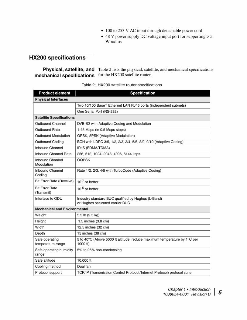
Physical, satellite, and mechanical specifications
Table 2 lists the physical, satellite, and mechanical specifications for the HX200 satellite router.
Table 2: HX200 satellite router specifications
Product element Specification
Physical Interfaces
Two 10/100 BaseT Ethernet LAN RJ45 ports (independent subnets)
One Serial Port (RS-232)
Satellite Specifications
Outbound Channel DVB-S2 with Adaptive Coding and Modulation
Outbound Rate 1-45 Msps (in 0.5 Msps steps)
Outbound Modulation QPSK, 8PSK (Adaptive Modulation)
Outbound Coding BCH with LDPC 3/5, 1/2, 2/3, 3/4, 5/6, 8/9, 9/10 (Adaptive Coding)
Inbound Channel IPoS (FDMA/TDMA)
Inbound Channel Rate 256, 512, 1024, 2048, 4096, 6144 ksps
Inbound Channel Modulation
OQPSK
Inbound Channel Coding
Rate 1/2, 2/3, 4/5 with TurboCode (Adaptive Coding)
Bit Error Rate (Receive) 10-7 or better
Bit Error Rate (Transmit)
10-5 or better
Interface to ODU Industry standard BUC qualified by Hughes (L-Band) or Hughes saturated carrier BUC
Mechanical and Environmental
Weight 5.5 lb (2.5 kg)
Height 1.5 inches (3.8 cm)
Width 12.5 inches (32 cm)
Depth 15 inches (38 cm)
Safe operating temperature range
5 to 40°C (Above 5000 ft altitude, reduce maximum temperature by 1°C per 1000 ft)
Safe operating humidity range
5% to 95% non-condensing
Safe altitude 10,000 ft
Cooling method Dual fan
Protocol support TCP/IP (Transmission Control Protocol / Internet Protocol) protocol suite
Chapter 1 • Introduction 1038054-0001 Revision B 5
6
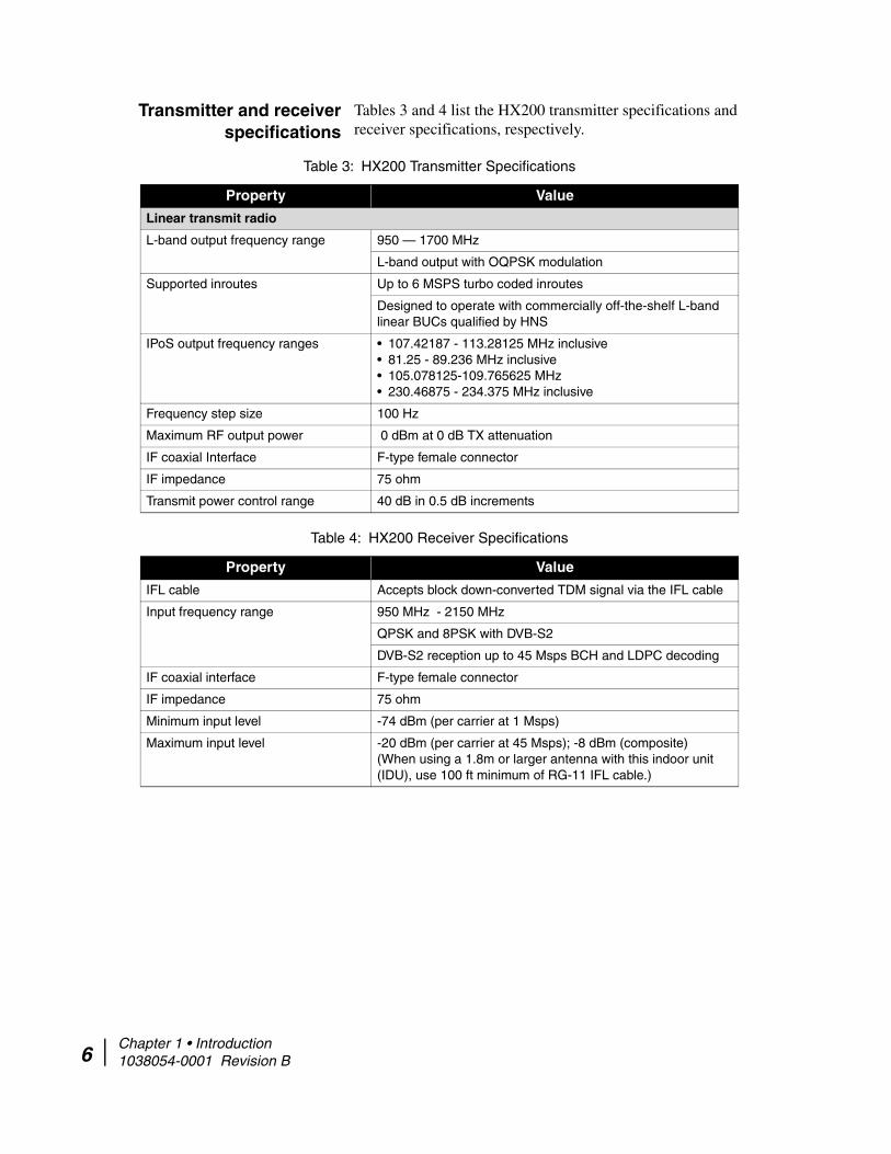
Transmitter and receiver specifications
Tables 3 and 4 list the HX200 transmitter specifications and receiver specifications, respectively.
Table 3: HX200 Transmitter Specifications
Property Value
Linear transmit radio
L-band output frequency range 950 — 1700 MHz
L-band output with OQPSK modulation
Supported inroutes Up to 6 MSPS turbo coded inroutes
Designed to operate with commercially off-the-shelf L-band linear BUCs qualified by HNS
IPoS output frequency ranges • 107.42187 - 113.28125 MHz inclusive• 81.25 - 89.236 MHz inclusive• 105.078125-109.765625 MHz• 230.46875 - 234.375 MHz inclusive
Frequency step size 100 Hz
Maximum RF output power 0 dBm at 0 dB TX attenuation
IF coaxial Interface F-type female connector
IF impedance 75 ohm
Transmit power control range 40 dB in 0.5 dB increments
Table 4: HX200 Receiver Specifications
Property Value
IFL cable Accepts block down-converted TDM signal via the IFL cable
Input frequency range 950 MHz - 2150 MHz
QPSK and 8PSK with DVB-S2
DVB-S2 reception up to 45 Msps BCH and LDPC decoding
IF coaxial interface F-type female connector
IF impedance 75 ohm
Minimum input level -74 dBm (per carrier at 1 Msps)
Maximum input level -20 dBm (per carrier at 45 Msps); -8 dBm (composite)(When using a 1.8m or larger antenna with this indoor unit (IDU), use 100 ft minimum of RG-11 IFL cable.)
Chapter 1 • Introduction 1038054-0001 Revision B
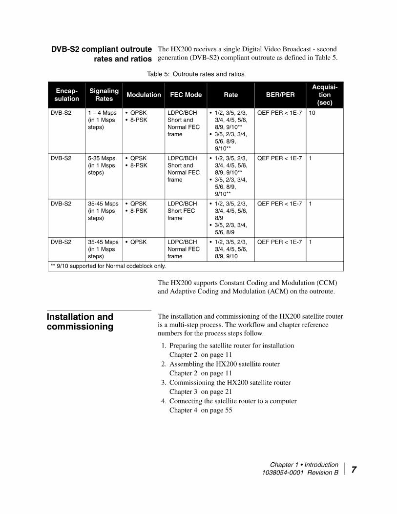
DVB-S2 compliant outroute rates and ratios
The HX200 receives a single Digital Video Broadcast - second generation (DVB-S2) compliant outroute as defined in Table 5.
The HX200 supports Constant Coding and Modulation (CCM) and Adaptive Coding and Modulation (ACM) on the outroute.
Installation and commissioning
The installation and commissioning of the HX200 satellite router is a multi-step process. The workflow and chapter reference numbers for the process steps follow.
1. Preparing the satellite router for installationChapter 2 on page 11
2. Assembling the HX200 satellite router Chapter 2 on page 11
3. Commissioning the HX200 satellite routerChapter 3 on page 21
4. Connecting the satellite router to a computerChapter 4 on page 55
Table 5: Outroute rates and ratios
Encap-sulation
Signaling Rates
Modulation FEC Mode Rate BER/PERAcquisi-
tion(sec)
DVB-S2 1 – 4 Msps (in 1 Msps steps)
• QPSK• 8-PSK
LDPC/BCHShort and Normal FEC frame
• 1/2, 3/5, 2/3, 3/4, 4/5, 5/6, 8/9, 9/10**
• 3/5, 2/3, 3/4, 5/6, 8/9, 9/10**
QEF PER < 1E-7 10
DVB-S2 5-35 Msps(in 1 Msps steps)
• QPSK• 8-PSK
LDPC/BCHShort and Normal FEC frame
• 1/2, 3/5, 2/3, 3/4, 4/5, 5/6, 8/9, 9/10**
• 3/5, 2/3, 3/4, 5/6, 8/9, 9/10**
QEF PER < 1E-7 1
DVB-S2 35-45 Msps(in 1 Msps steps)
• QPSK• 8-PSK
LDPC/BCHShort FEC frame
• 1/2, 3/5, 2/3, 3/4, 4/5, 5/6, 8/9
• 3/5, 2/3, 3/4, 5/6, 8/9
QEF PER < 1E-7 1
DVB-S2 35-45 Msps(in 1 Msps steps)
• QPSK LDPC/BCHNormal FEC frame
• 1/2, 3/5, 2/3, 3/4, 4/5, 5/6, 8/9, 9/10
QEF PER < 1E-7 1
** 9/10 supported for Normal codeblock only.
Chapter 1 • Introduction 1038054-0001 Revision B 7

8
Commissioning is the process of registering an HX200 satellite router for service. During the commissioning process you may use auto selection or manual entry of parameters.
• Auto Selection - Allows you to choose the Network Access Provider (NAP) from a predetermined list of providers. Many of the commissioning parameters are automatically configured for the provider chosen.
• Manual Entry - This mode requires you to enter all parameters manually.
Contact information If you experience installation problems with the HX200 satellite router, try the Diagnostic Utilities on page 64.
For warranty or repair support, the contact information varies depending on the location. If the customer needs service, warranty or repair support, they should contact their customer service representative in accordance with their service agreement.
Table 6: Radios and LNBs
Description VendorHughes product
number
Saturated Ku-Band Radios
TG 2W, 2M. DOM HNS 1500192-0221
TG 2W, 1M, EUT HNS 1500192-0122
TG 2W, 1M, INT HNS 1500192-0123
1W Pure Anubis/LNB/Tria HNS 1500172-0101
2W Pure Anubis/LNB/Tria HNS 1500172-0102
Saturated C-Band Radios
2W MTI (India-C) HNS 1028050-0006
2W MTI (Extended-C) HNS 1036720-0001
Linear Ku-Band Radios
1W Linear BUC NJRC / NJT5115F 9506265-0001
2W Linear BUC NJRC / NJT5037F 9506221-0001
3W Linear BUC NJRC / NJT5116F 9506252-0001
4W Linear BUC NJRC / NJT5017FL 9502667-0002
4W Linear BUC/Tria/LNB Andrew Corp / DRU15F16HX
1502302-0001
6W Linear BUC NJRC / NJT5127N 9505264-0001
8W Linear BUC NJRC / NJT5118N 9506220-0001
Linear C-Band Radios
5W Linear BUC NJRC / NJT5669F 9502666-0001
Chapter 1 • Introduction 1038054-0001 Revision B

10W Linear BUC NJRC/ NJT5762N 9506222-0001
Ku-Band Low Stability LNBs
Dom/Intl LNB MTI 1500320-0006
Intelsat MTI 1500287-0001
AsiaSat/Eutelsat MTI 1500287-0003
Universal Ku-Band LNB Invacom 1501882-0002
C-Band Low Stability LNBs
Extd C-Band LNB MTI 1024573-0001
India C-Band LNB HNS (MTI) 1024573-0002
Ku-Band Internal PLL (High Stability) LNBs
Universal Ku Band HS LNB ASC / 1501654-0001
Ku-Band External Reference PLL LNBs
Domestic Ku Band PLL LNB Invacom / SPV-65SM 1502442-0002
Intelsat Ku Band PLL LNB Invacom / SPV-55SM 1502442-0001
Asia/Eutelsat Ku Band PLL LNB Invacom / SPV-75SM 1502442-0003
C-Band External Reference PLL LNBs
C Band PLL LNB Norsat / 3020XF 1502443-0001
Table 6: Radios and LNBs
Description VendorHughes product
number
Chapter 1 • Introduction 1038054-0001 Revision B 9

10
Chapter 1 • Introduction 1038054-0001 Revision B
Chapter 2
Assembling and connecting HX200 hardware
This chapter explains how to assemble and make the connections to the HX200 satellite router.
Preparing for the installation
Items required for installation
To install an HX200 satellite router, first ensure that you have the following items listed below:
• HX200 satellite router• Power cord• SBC.cfg file (if you are instructed to upload it)• Installation specification or work order
Items required for stabilized platforms
If you installing the HX200 for a stabilized platform, you will need the items listed below:
Seatel antenna Components provided by Hughes:
• NMEA cables and RS232/RS422 converter - Part Numbers: 1502199-0001 and 1502200-0001.
• RX Lock/TX Mute Cable - Part Number: 1502198-0001• 48V Power supply• IFL (F connectors) for RX and TX interconnect between the
HX200 and the ACU• Mounting kit for the terminal mounting strip.• Mounting kit for the splitter.
For all other information regarding the Seatel install, refer to the Installation and Operation Manual for the Sea Tel Model DAC-2202 Antenna Control Unit (Document No. 126523 Revision D).
Azimuth antenna Components provided by Hughes:
• NMEA cables and RS232/RS422 converter - Part Number: 1502035-0001
Chapter 2 • Assembling and connecting HX200 hardware 1038054-0001 Revision B 11

12
• RX Lock/TX Mute Cable - Part Number: 1502036-0001• Diagram• IFL (F connectors) for RX and TX interconnect between the
HX200 and the ACU
For all other information regarding the Azimuth install, refer to the A117 3 Axis Stabilizer Installation and Operations Manual (Version 2.0).
Confirming installer laptop and site requirements
Before installing the HX200, you must confirm that the installer laptop and the computer at the installation site meet specific requirements.
Installer laptop requirements The installer laptop must meet the following requirements:
• Ethernet-enabled network interface card (NIC) and Ethernet cable.
• Operating system with graphical user interface, such as Windows, Linux with X Windows, or Mac OS X; and with TCP/IP protocol support and client-side DHCP enabled. See Appendix A – Configuring a Windows computer to support DHCP, on page 105.
• A Web browser such as Internet Explorer with proxy settings disabled. See Appendix C – Disabling a Web browser proxy connection, on page 121.
• The latest version of the sbc.cfg file (if instructed to install it).
Remote site requirements IP devices connected to an HX200 satellite router must implement the standard TCP/IP stack and provide an Ethernet interface; otherwise there is no constraint to the platforms and operating systems of devices attached to the satellite routers.
For example, PCs, MACs, SPARC and Alpha workstations, AS400 systems, and so on, can all be used on LANs connected to an HX200 satellite router, running operating systems such as Windows, Linux, Solaris, MAC OS X, AIX, VMS and others..
Note: Prior to beginning the installation, confirm that the installer laptop is configured to support DHCP. See Appendix A – Configuring a Windows computer to support DHCP for instructions on configuring DHCP on a Windows computer.
Chapter 2 • Assembling and connecting HX200 hardware 1038054-0001 Revision B
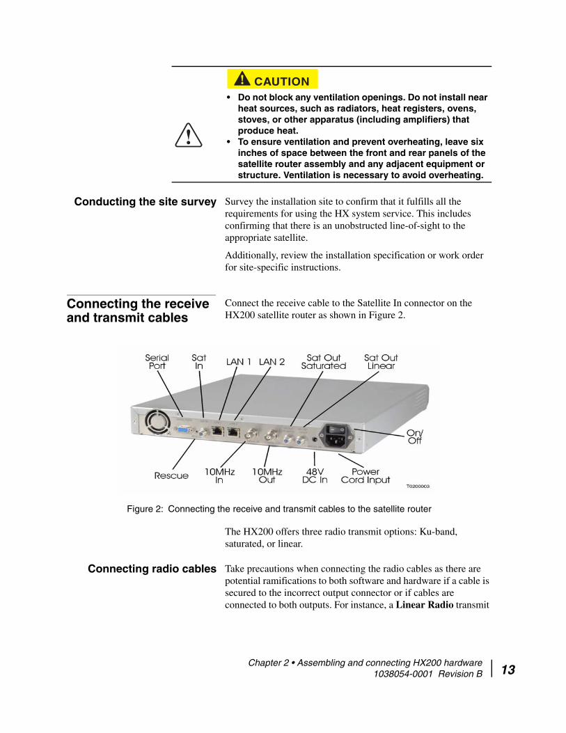
Conducting the site survey Survey the installation site to confirm that it fulfills all the requirements for using the HX system service. This includes confirming that there is an unobstructed line-of-sight to the appropriate satellite.
Additionally, review the installation specification or work order for site-specific instructions.
Connecting the receive and transmit cables
Connect the receive cable to the Satellite In connector on the HX200 satellite router as shown in Figure 2.
The HX200 offers three radio transmit options: Ku-band, saturated, or linear.
Connecting radio cables Take precautions when connecting the radio cables as there are potential ramifications to both software and hardware if a cable is secured to the incorrect output connector or if cables are connected to both outputs. For instance, a Linear Radio transmit
CAUTION• Do not block any ventilation openings. Do not install near
heat sources, such as radiators, heat registers, ovens, stoves, or other apparatus (including amplifiers) that produce heat.
• To ensure ventilation and prevent overheating, leave six inches of space between the front and rear panels of the satellite router assembly and any adjacent equipment or structure. Ventilation is necessary to avoid overheating.
Figure 2: Connecting the receive and transmit cables to the satellite router
Chapter 2 • Assembling and connecting HX200 hardware 1038054-0001 Revision B 13

14
cable should not be connected to the Sat Out Saturated connector on the back of the HX200 satellite router.
.
Use either the Manual Commissioning screen or one of the Satellite Based Commissioning screens to select the radio type as described in Chapter 3 – Commissioning the HX200 satellite router on page 21. You may select only one radio transmit option at any time.
Connecting the Ethernet and power cables
Select a location for the satellite router that accommodates all required cable connections, including the power source.
Using Figure 2 as a reference, connect the Ethernet cable:
1. Place the satellite router in the desired installation location.2. Connect the installer PC to the satellite router with an
Ethernet cable. Make sure no Ethernet routers or switches are currently connected between the satellite router and the installer PC.
3. Connect the power cable.
CAUTION
Do not connect or disconnect a radio cable while the IDU is powered on; this action may result in damage to the BUC.
CAUTIONCaution: The transmit and receive cable connectors must be securely tightened.
• Make sure each connector is properly aligned (not cross-threaded).
• Finger tight with no connector play is adequate.
Note: The satellite router may operate correctly when first installed even if the transmit and receive cable connectors are not adequately tightened. However, problems could develop later. Therefore, correct operation of the satellite router is not an indication that the cables are adequately tightened.
Note: A surge protector is recommended.
Chapter 2 • Assembling and connecting HX200 hardware 1038054-0001 Revision B

Serial port interface connections
Figure 3 shows signals supported by the HX200 for the control and status of servo actuated antenna systems.
Signal details are as follows:
• Signals: on pins 14 and 15 of the Serial2 female-D connector at the rear of the unit
• Interface: RS232 electrical levels • 15kV ESD protection• Suggested maximum cable length: not to exceed
approximately 150 ft • Antenna mis-point transmitter disable control
– Input to HX200 on serial port pin 14
Note: Do not connect any devices to the HX200 at this time. Connect serial and Ethernet devices to the device only after it is fully installed and commissioned.
CAUTIONDo not connect or disconnect the Tx or Rx IFL cable while the IDU is powered on; this action may result in damage to the BUC, LNB and/or IDU.
Figure 3: HX200 antenna signals
Chapter 2 • Assembling and connecting HX200 hardware 1038054-0001 Revision B 15

16
– This HX200 input signal is used to indicate the antenna system has detected a mis-point
– The HX200 disables its transmitter within 45 milliseconds after this signal transitions from -5 volts to +5 volts
– The HX200 enables its transmitter within 45 milliseconds after this signal transitions from +5 volts to 15 volts
– This signal defaults to transmit enable in the absence of external connection
• HX200 demodulator lock indicator– Output from the HX200 on serial port pin 15– This HX200 output signal is used to indicate to the antenna
system the current status of the HX-200 demodulator– Signal reaction time to demodulator lock state change -
nominally 20 milliseconds– Demodulator lock is indicated by +5 volts– Demodulator unlock is indicated by -5 volts– +5V volts is output on this signal with SQF values from
31-99– -5V volts is output on this signal with SQF values from
1-30 • NMEA/GPS serial data interface
– Transmit data from the HX200 on pin 11– Receive data to the HX200 on pin 12– Signal ground on pin 13
Connecting the hardware for stabilized platforms
The hardware components for stabilized platforms can be assembled in one of two configurations as shown in Figure 4 on page 17 and Figure 5 on page 18. Select the correct configuration for your site and assemble according to the following figures based on whether a Seatel or Azimuth antenna is deployed with the HX200.
Follow all installation and safety instructions in the Installation and Operation Manual for Sea Tel Model DAC-2202 Antenna Control Unit (Document No. 126523, Revision D) or the A117 3
Chapter 2 • Assembling and connecting HX200 hardware 1038054-0001 Revision B

Axis Stabilizer Installation and Operations Manual (Version 2.0).
Figure 4: Connecting the hardware components - Seatel DAC 2200 configuration
Chapter 2 • Assembling and connecting HX200 hardware 1038054-0001 Revision B 17

18
.
Powering up and observing the LEDs
Turn the AC power switch located on the satellite router to ON.
When power is applied to the HX200, or after it resets, the satellite router light-emitting diodes (LEDs) will light in the following sequence.
1. All LEDs illuminate for 1/2 second.2. The Power LED lights up steadily, indicating that the HX200
is powered up.
Figure 5: Connecting the hardware components - Azimuth KNS-150 configuration
Chapter 2 • Assembling and connecting HX200 hardware 1038054-0001 Revision B

3. The LAN LED lights up within 30 seconds, indicating that LAN connectivity is detected.
4. The Power LED blinks, indicating that the unit is not commissioned and therefore is running fallback.bin rather than main.bin.
Stabilized platforms Refer to the Installation and Operation Manual for Sea Tel Model DAC-2202 Antenna Control Unit (Document No. 126523, Revision D) or the A117 3 Axis Stabilizer Installation and Operations Manual (Version 2.0) for detailed installation instructions.
Note: In countries outside North America, the HX200 may be plugged directly into a 240V outlet with a replacement power cord. Different countries may have different standards and requirements.
CAUTION• To remove power from a satellite router, turn the power
switch to the OFF position.• Satellite routers must be used with 100/240-volt AC
Input.• If the satellite router is installed in any country outside
the United States and Canada, always observe the power standards and requirements of that country.
Chapter 2 • Assembling and connecting HX200 hardware 1038054-0001 Revision B 19

20
Chapter 2 • Assembling and connecting HX200 hardware 1038054-0001 Revision B
Chapter 3
Commissioning the HX200 satellite router
This chapter explains how to register or commission a satellite router for service. Procedures are provided for the following commissioning methods:
• Manual commissioning on page 21• Satellite-based commissioning on page 37
Manual commissioning The most common method of commissioning the satellite router is manual commissioning. Manual commissioning assumes the HX200 satellite router has already been pre-configured at the NOC, the outdoor unit (ODU) and indoor unit (IDU) have been successfully installed, and the dish is pointed correctly. If all the above conditions are met, you can manually commission the router. The router can be commissioned through the Manual Commissioning Web Interface using any computer that has an Ethernet port and an HTTP browser installed on it.
The following configuration for the installer laptop is recommended:
• Windows 2000 or higher• Ethernet card or Ethernet port connected directly to the VSAT
and set to Auto-Negotiate • TCP/IP settings for the Ethernet card set to Obtain an IP
address automatically and Obtain DNS server address automatically
• Firewall software (such as Norton Internet Security) disabled since these may interfere with commissioning by not allowing execution of CGI scripts
• Internet Explorer 5.5 or later, configured as follows:
Note: The procedures in this chapter assume that a Windows computer is used to commission the satellite router. If a different platform is used, substitute commands appropriate to that platform.
Chapter 3 • Commissioning the HX200 satellite router 1038054-0001 Revision B 21

22
– Under Tools → Internet Options → General Tab → Settings → Check for newer versions of stored pages, select the Every Visit to the Page option.
– Under Tools → Internet Options → Connections Tab verify that Never dial a connection is selected.
– Under Tools → Internet Options → Connections Tab → LAN Settings verify that all checkboxes are unchecked.
• Browsers supported: Internet Explorer 5.0 (or higher), Netscape 6.0 (or higher), and Mozilla Firefox 1.0.2 (or higher)
The manual commissioning process consists of the following tasks:
• Accessing the manual commissioning interface• Antenna pointing
Accessing the manual commissioning interface
Follow these steps to access the manual commissioning interface:
The Manual Commissioning interface can be accessed from any browser as follows:
1. Type the following URL to navigate to the Advance page:http://192.168.0.1/fs/advanced/advanced.html
Note: The satellite router’s serial number must be loaded at the system gateway by an HX system operator in order to complete the manual commissioning process.
Chapter 3 • Commissioning the HX200 satellite router 1038054-0001 Revision B

2. Click the Setup link (Figure 6) to display the Setup page shown in Figure 7.
Figure 6: Advance page
Chapter 3 • Commissioning the HX200 satellite router 1038054-0001 Revision B 23

24
3. Click the VSAT Manual Commissioning link on the Setup page (Figure 7) to display the HX200 Manual Commissioning Page as shown in Figure 8.
Alternately, you can navigate to the Terminal Manual Commissioning Page from the System Control Center as follows:a. Type the following URL:http://192.168.0.1
b. When running fallback, click the Advanced Commissioning Options link.
c. Click the VSAT Manual Commissioning link on the Setup page as shown in Figure 7.
4. Enter or select the appropriate parameters. These parameters may be provided to you in an installation specification, work order, or in another form of communication from the installation point-of-contact.
Figure 7: Commissioning Setup page
Chapter 3 • Commissioning the HX200 satellite router 1038054-0001 Revision B

The parameters on the Manual Commissioning page are divided into the following six sections as shown in Figure 8:
Satellite ParametersVSAT parametersLAN ParametersManagement ParametersReceive Radio Parameters Transmit Radio Parameters
Figure 8: Broadband Satellite HX200 Manual Commissioning screen
Chapter 3 • Commissioning the HX200 satellite router 1038054-0001 Revision B 25

26
5. As an example, enter or select the appropriate section by clicking the + sign to expand the category as shown Figure 9.
After entering the information for all sections, click Save Configuration.
The terminal reboots after saving the configuration.
Figure 9: Expanded categories
Note: Clicking the Cancel button discards all the changes and closes the Manual Commissioning page.
Note: If an incorrect value is entered for any field on the Manual Commissioning page, an error message displays and the form cannot be submitted until the error is corrected.
Chapter 3 • Commissioning the HX200 satellite router 1038054-0001 Revision B

Entering Satellite Parameters These parameters are used to lock the tuner and the demod to the outroute. The following parameters must be entered (Figure 10). Use your work order to enter these parameters.
• DVB Framing Mode (drop-down) - Required– DVB-S– DVB-S2 CCM– DVB-S2 ACM
• Longitude - Defines the location of the satellite being used.– Degrees – Hemisphere (drop-down)
• East• West
• Frequency (x 100Khz) - Required• Symbol Rate (Sps) - Required• LNB 22KHz Switch (drop-down)• Receive Polarization - Required
– Vertical– Horizontal– Left
Figure 10: Satellite Parameters section
Chapter 3 • Commissioning the HX200 satellite router 1038054-0001 Revision B 27

28
– Right• Transmit Polarization (drop-down) - Required
– Horizontal– Vertical– Right– Left
• OTA Frequency (X 100KHz) - Normally not used unless the sbc.cfg file is not up to date and the LNB does not appear on the LNB drop-down list.
Entering VSAT Parameters These parameters gives the geographic location of the satellite router. The following parameters must be entered (Figure 11):
• Longitude– Degrees– Minutes– Hemisphere (drop-down)
• East• West
• Latitude– Degrees
Figure 11: VSAT Parameters section
Chapter 3 • Commissioning the HX200 satellite router 1038054-0001 Revision B
– Minutes– Hemisphere (drop-down)
• North• South
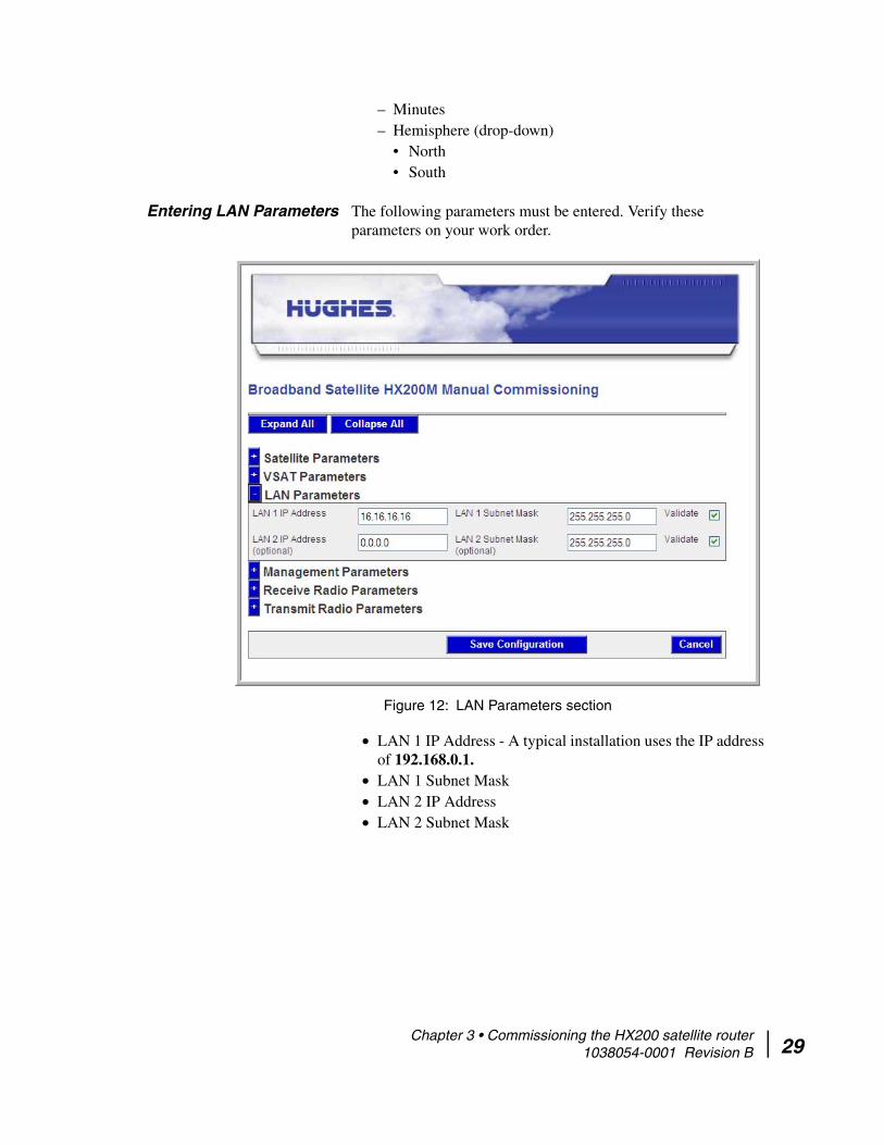
Entering LAN Parameters The following parameters must be entered. Verify these parameters on your work order.
• LAN 1 IP Address - A typical installation uses the IP address of 192.168.0.1.
• LAN 1 Subnet Mask• LAN 2 IP Address • LAN 2 Subnet Mask
Figure 12: LAN Parameters section
Chapter 3 • Commissioning the HX200 satellite router 1038054-0001 Revision B 29
30
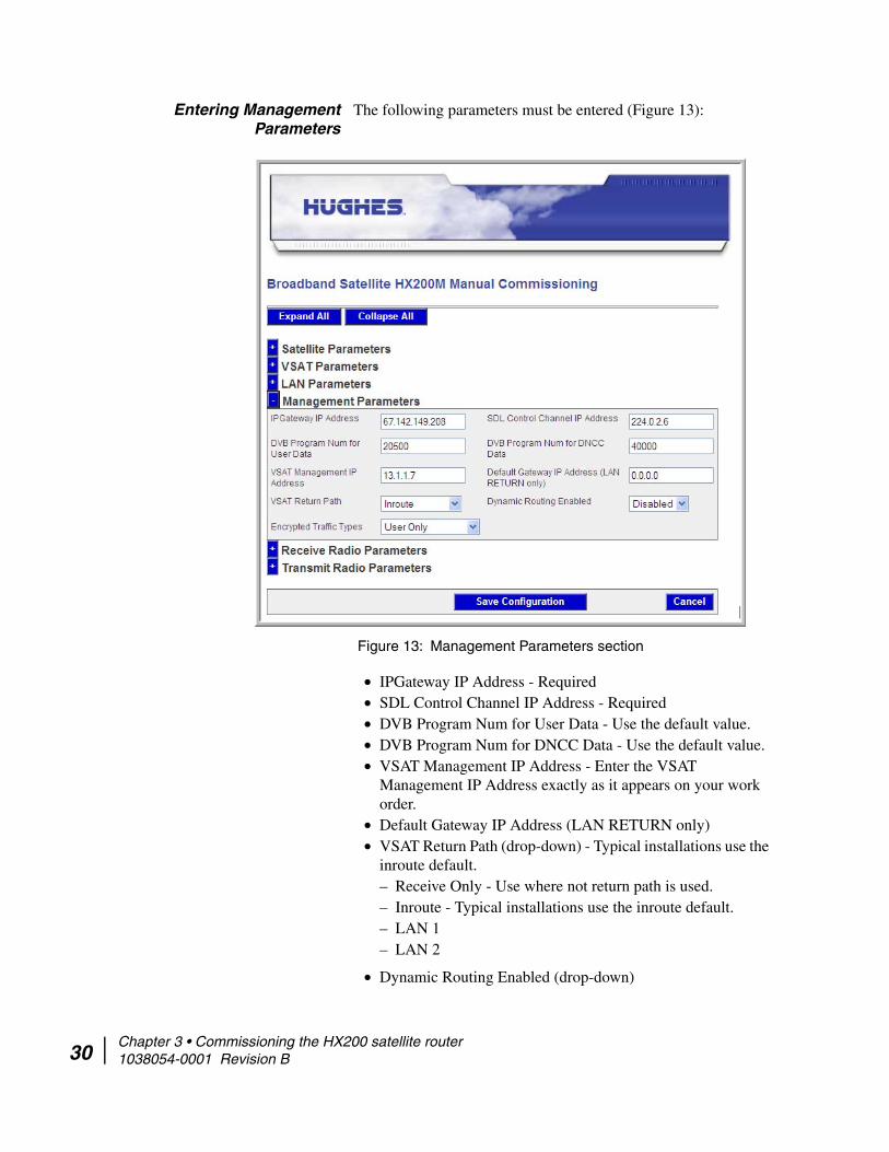
Entering Management Parameters
The following parameters must be entered (Figure 13):
• IPGateway IP Address - Required• SDL Control Channel IP Address - Required• DVB Program Num for User Data - Use the default value.• DVB Program Num for DNCC Data - Use the default value.• VSAT Management IP Address - Enter the VSAT
Management IP Address exactly as it appears on your work order.
• Default Gateway IP Address (LAN RETURN only)• VSAT Return Path (drop-down) - Typical installations use the
inroute default. – Receive Only - Use where not return path is used.– Inroute - Typical installations use the inroute default. – LAN 1– LAN 2
• Dynamic Routing Enabled (drop-down)
Figure 13: Management Parameters section
Chapter 3 • Commissioning the HX200 satellite router 1038054-0001 Revision B
– Disabled - Typical installations use this value.– Enabled
• Encrypted Traffic Types (drop-down)
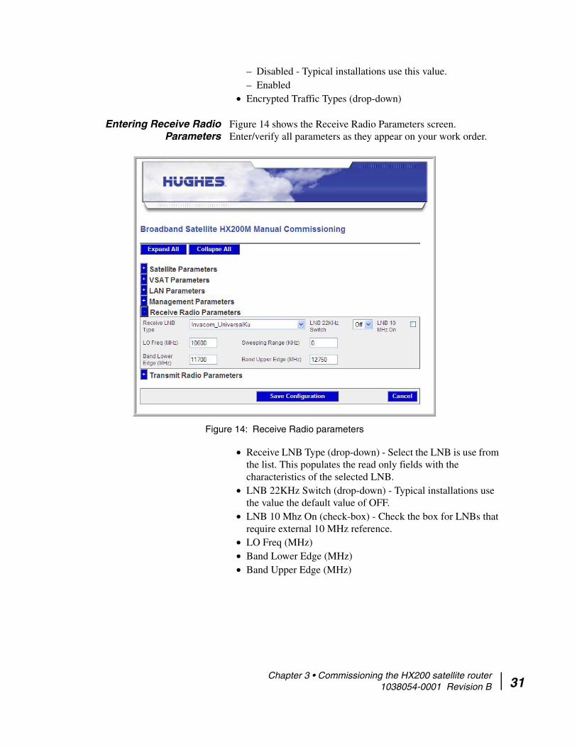
Entering Receive Radio Parameters
Figure 14 shows the Receive Radio Parameters screen. Enter/verify all parameters as they appear on your work order.
• Receive LNB Type (drop-down) - Select the LNB is use from the list. This populates the read only fields with the characteristics of the selected LNB.
• LNB 22KHz Switch (drop-down) - Typical installations use the value the default value of OFF.
• LNB 10 Mhz On (check-box) - Check the box for LNBs that require external 10 MHz reference.
• LO Freq (MHz)• Band Lower Edge (MHz)• Band Upper Edge (MHz)
Figure 14: Receive Radio parameters
Chapter 3 • Commissioning the HX200 satellite router 1038054-0001 Revision B 31

32
Entering Transmit Radio Parameters
Figure 15 shows the Transmit Radio Parameters screen.
1. Enter/verify all parameters as they appear on your work order.
2. Select the transmit radio used - Saturated or Linear.
Saturated Radio
• Select either 1 or 2 watts.• No other saturated radio selections are required.
Linear Radio
• Select the radio from the drop-down list. This populates the following read only fields.– LO Frequency (MHz) – Band Lower Edge (MHz)– Band Upper Edge (MHz) – Radio Wattage (W)– Total Gain (dB)– 1 db G.C.P(dB)
Figure 15: Transmit Radio Parameters screen
Chapter 3 • Commissioning the HX200 satellite router 1038054-0001 Revision B

• Transmitted 10 MHz Off - Typical installations use the default value, unchecked (10 MHz is on to BUC).
• Set Maximum Tx Power/Minimum Attenuation - See section below for details.
• Enable Spreading - Typical installations use the default value - unchecked.
• Use External 10 MHz Signal - Typical installations use the default value - unchecked.
3. Click Save Configuration.
Set Maximum Tx Power/Minimum Attenuation
These values are used to control the maximum output power a modem can transmit. The reason this must be set correctly is so that the BUC input level is not high enough to cause the BUC to saturate. If the BUC saturates it can cause ACI, transmit carrier distortion, or excessive power compared to other terminals, any of which could cause network degradation or outage conditions.
The maximum modem output power is 0 dB, and there is an attenuator that is used by the modem operational software to control the output power. If the Set Maximum Tx Power box is checked, then the terminal will ensure that the attenuation applied to the output signal never drops below the configured Minimum Attenuation value, effectively limiting the maximum modem output power.
The appropriate Minimum Attenuation value must be calculated based on the TX IFL cable length, cable attenuation, and BUC maximum power input. To determine this setting, you must first know the maximum allowable input level into the BUC. This is found by taking the maximum allowable BUC power out in dB, then subtracting the BUC gain. Then, knowing the cable loss over the length of TX IFL in use, the maximum modem output value is known, and therefore the Minimum Attenuation value can be calculated.
As an example, assume we are using an ODU with a maximum allowable power output of 36 dB, with a gain of 56 dB. The maximum allowable input to the BUC in the ODU is -20 db (i.e. 36 dB - 56 dB). With a typical 100 foot cable run, where the cable loss is 8 dB per 100 feet, the cable will introduce an 8 dB signal loss. Thus the maximum allowable power out at the input to the cable (i.e. the output from the modem) is -12 dB. Given the modem output power with no attenuation is 0 dB, the Minimum Attenuation value should be set at 12 dB.
Chapter 3 • Commissioning the HX200 satellite router 1038054-0001 Revision B 33
34
NOC override In some cases the NOC may need to override the allowed inroute symbol rates mask due to the installer’s selection. In order to override the selection from the NOC, the following parameter must be set in the satellite router’s InrouteProfile:
shinrtCfLocalInrtMaskOverride=2
As a result of the NOC override, the satellite router uses the inroute rates specified by the NOC instead of the transmit radio selection.
Error checks The Javascript Form Check is used on all relevant fields in the Manual Commissioning interface. If the installer enters an incorrect value for any field, an error message displays and the form cannot be submitted until the error is corrected.
Antenna pointing Follow these steps to use the Antenna Pointing feature on the HX200 web-based interface to peak the receive and transmit signals:
1. Turn off the HX200 using the power switch on the rear panel.2. Connect the receive and transmit coaxial cables to the
HX200.3. Place the DAPT in the receive cable line, if applicable.4. Apply power to the HX200.5. Open a web browser on the installer laptop and navigate to
the Broadband Satellite Setup screen as explained in Accessing the manual commissioning interface on page 22.
Chapter 3 • Commissioning the HX200 satellite router 1038054-0001 Revision B
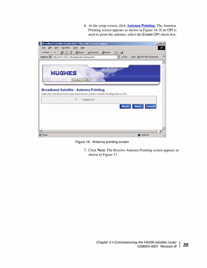
6. At the setup screen, click Antenna Pointing. The Antenna Pointing screen appears as shown in Figure 16. If an OPI is used to point the antenna, select the Enable OPI check box.
7. Click Next. The Receive Antenna Pointing screen appears as shown in Figure 17.
Figure 16: Antenna pointing screen
Chapter 3 • Commissioning the HX200 satellite router 1038054-0001 Revision B 35

36
8. To view a graphic representation of the current signal quality, click Display Signal Strength.
9. Use the Signal Quality indication to peak the receive pointing as instructed in the antenna installation manual.
10. After peaking the signal, close the Signal Quality window and click Exit on the Receive Antenna Pointing screen to exit the Antenna Pointing feature.
11. If required, the satellite router may need to run automatic cross-polarization (ACP) if it is present. If ACP is present, the timing units tells the satellite router it is present, and this
Figure 17: Receive pointing
Note: If the Signal Quality window is not visible on the display, minimize the other windows until you can see it.
Note: You must peak the signal even when the antenna is locked to it.
Chapter 3 • Commissioning the HX200 satellite router 1038054-0001 Revision B

forces the timing units to run ACP. The satellite router automatically inquires for validation when the timing unit indicates ACP is present. Based on the ACP configuration, the satellite router may occasionally request re-validation.
Satellite-based commissioning
Satellite-based commissioning (SBC) is the another commissioning method. Commissioning the satellite router using SBC consists of the following tasks:
• Obtaining an IP address from the HX200 satellite router• Uploading the SBC configuration file to the HX200• Commissioning the HX200
Obtaining an IP address from the HX200 satellite
router
1. Ensure that the installer laptop is configured to support the Dynamic Host Control Protocol (DHCP) to obtain an IP address. Refer to Appendix A for instructions on how to configure a Windows computer to use DHCP.
2. Verify that the installer laptop is connected to the HX200 by an Ethernet cable.
3. Open a command window on the installer laptop and obtain an IP address from a DHCP server. For example, on a Windows computer, type:ipconfig /release <Enter>
4. Type ipconfig /renew <Enter>.
If the HX200 does not assign an IP address to the installer laptop, restart the laptop to obtain the IP address. The assigned IP address will be on the same subnet as the IP of the connected satellite router LAN port, typically 192.168.0.2.
5. Execute a ping test to verify an active Ethernet connection between the HX200 and the installer laptop:
Note: In the following procedure, installer laptop refers to the computer—typically a laptop—used to connect to and commission the HX200.
Note: To view all IP configuration commands on a Windows platform, type ipconfig /help at a command line prompt and press ENTER.
Chapter 3 • Commissioning the HX200 satellite router 1038054-0001 Revision B 37

38
a. Open a command window on the installer laptop.b. Type ping 192.168.0.1.
c. Press ENTER.
A successful ping test is shown in Figure 18.
A failed ping test is shown in Figure 19. If the ping test fails, make sure that the installer laptop Network Interface Card (NIC) is properly installed and that the installer laptop is properly configured to use DHCP. See Appendix A for more information.
If the NIC is installed properly and the installer laptop is configured properly, make sure all cable connections are secure. (See the Caution statement that follows Figure 2 on page 13).
Note: If an alternate IP address was assigned to the satellite router at the system gateway, ping that IP address instead.
Figure 18: Successful ping
Figure 19: Failed ping
Chapter 3 • Commissioning the HX200 satellite router 1038054-0001 Revision B

If all cable connections are secure:– Shut down and power off the satellite router.– Shut down and power off the installer laptop.– Turn the satellite router back on.– Turn the installer laptop back on.
Also, make sure that neither an Ethernet router nor a switch is currently connected to the satellite router, then try the ping test again. If the test is still unsuccessful, contact Technical Support for assistance.
Uploading the SBC configuration file to the
HX200
The SBC configuration file (sbc.cfg) contains satellite information that SBC and the auto-commissioning server (ACS) must use during the commissioning process. Once you have obtained the sbc.cfg file, save it on the installer laptop, making sure to note the location in which the file is saved; then complete the steps below.
1. Open a browser on the installer laptop.2. Type http://192.168.0.1/fs/registration/
setup.html in the address bar and press ENTER. If an alternate IP address was assigned to the satellite router at the
Note: If you do not have to upload an sbc.cfg file to the satellite router, skip this section and go to Commissioning the HX200 on page 41.
Chapter 3 • Commissioning the HX200 satellite router 1038054-0001 Revision B 39

40
HX system gateway, enter that IP address instead. The Broadband Satellite Setup screen appears as shown below.
3. Click Config File Upload.
4. On the Configuration File Upload screen, click Browse and navigate to the location on the installer PC where the sbc.cfg file is saved.
5. Select the file and click Open. 6. Click Upload.7. Click Close to return to the Setup screen.
Figure 20: Setup screen
Note: Do not click Zip Code File Upload; this link is used to update the ZIP code table in the satellite router.
Chapter 3 • Commissioning the HX200 satellite router 1038054-0001 Revision B

Commissioning the HX200 Follow these steps to commission the satellite router:
1. From the Broadband Satellite Setup screen, click Registration - Installer. The Antenna Location screen appears as shown in Figure 21.
2. Enter the ZIP code of the location in which you are installing the satellite router and click Next. If installing the HX200 outside the United States, you can enter the location manually by completing steps a and b below.a. Select the Enter Location Manually check box and click
Next. The Manual Entry of Antenna Location screen appears as shown in Figure 22.
Figure 21: Antenna Location screen
Chapter 3 • Commissioning the HX200 satellite router 1038054-0001 Revision B 41

42
b. Enter the correct latitude and longitude for the location and click Next.
Figure 22: Entering location manually
Chapter 3 • Commissioning the HX200 satellite router 1038054-0001 Revision B

3. The Verification of Antenna Location screen appears as shown in Figure 23 on page 43. Click Next.
4. At the Satellite Parameters screen as shown in Figure 24, click the Satellite Transponders drop-down menu, select the satellite and transponder listed either on the work order or in the installation specification, and click Next.
The satellite parameters should have been provided to you in either a technical update e-mail or an installation specification. If the satellite and transponder for your installation are not listed in the drop-down menu, and you were not provided with an sbc.cfg file, you must complete steps a through d below to enter the satellite parameters manually.
a. Select the Enter satellite parameters manually check box on the Satellite Parameters screen.
Figure 23: Verification of Antenna Location screen
Chapter 3 • Commissioning the HX200 satellite router 1038054-0001 Revision B 43

44
b. Click Next. The Manual Entry of Satellite Parameters screen appears as shown in Figure 25.
c. Enter or select the appropriate parameters.• Longitude • Frequency• Symbol rate• Receive polarization• Transmit polarization• 22KHz tone• Frequency Band/Modulation• Digital video broadcast (DVB) Mode• DVB Program Number (User Data)• DVB Program Number (DNCC Data)
Figure 24: Selecting the satellite and transponder
Chapter 3 • Commissioning the HX200 satellite router 1038054-0001 Revision B
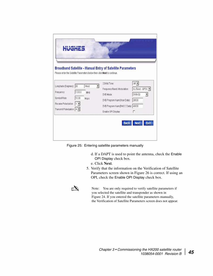
d. If a DAPT is used to point the antenna, check the Enable OPI Display check box.
e. Click Next.5. Verify that the information on the Verification of Satellite
Parameters screen shown in Figure 26 is correct. If using an OPI, check the Enable OPI Display check box.
Figure 25: Entering satellite parameters manually
Note: You are only required to verify satellite parameters if you selected the satellite and transponder as shown in Figure 24. If you entered the satellite parameters manually, the Verification of Satellite Parameters screen does not appear.
Chapter 3 • Commissioning the HX200 satellite router 1038054-0001 Revision B 45

46
6. Click Next. 7. The Receive LNB Selection screen appears as shown in
Figure 27.
8. Select the LNB in use from the drop-down list. Click Next.9. Verify your information is correct on the Verification of
Receive LNB Parameters screen as shown in Figure 28 on page 47. Click Next.
Figure 26: Verifying satellite parameters
Figure 27: Select Receive LNB Selection screen
Chapter 3 • Commissioning the HX200 satellite router 1038054-0001 Revision B
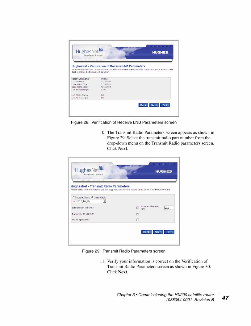
10. The Transmit Radio Parameters screen appears as shown in Figure 29. Select the transmit radio part number from the drop-down menu on the Transmit Radio parameters screen. Click Next.
11. Verify your information is correct on the Verification of Transmit Radio Parameters screen as shown in Figure 30. Click Next.
Figure 28: Verification of Receive LNB Parameters screen
Figure 29: Transmit Radio Parameters screen
Chapter 3 • Commissioning the HX200 satellite router 1038054-0001 Revision B 47

48
.
12. The Receive Antenna Pointing screen appears as shown in Figure 31.
13. To view a graphic representation of the current signal quality (Figure 32), click Display Signal Strength. Click Close.
Figure 30: Verification of Transmit Radio Parameters screen
Figure 31: Receive Antenna Pointing
Chapter 3 • Commissioning the HX200 satellite router 1038054-0001 Revision B

14. Peak the receive pointing as instructed in the antenna installation manual.
15. After peaking the signal, click Close to close the Signal Quality window.
16. Click Next.17. The satellite router will need to run automatic
cross-polarization (ACP). The timing units tells the satellite router it is present, and this forces the timing units to run ACP. The satellite router automatically inquires for validation when the timing unit indicates ACP is present. Based on the ACP configuration, the satellite router may occasionally
Note: If the Signal Quality window is not visible on the display, minimize the other windows until you can see it.
Figure 32: Signal strength
Note: You must peak the signal even when the antenna is locked to it.
Chapter 3 • Commissioning the HX200 satellite router 1038054-0001 Revision B 49
50
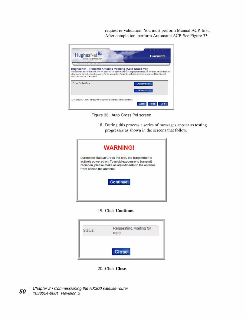
request re-validation. You must perform Manual ACP, first. After completion, perform Automatic ACP. See Figure 33.
18. During this process a series of messages appear as testing progresses as shown in the screens that follow.
19. Click Continue.
20. Click Close.
Figure 33: Auto Cross Pol screen
Chapter 3 • Commissioning the HX200 satellite router 1038054-0001 Revision B

21. The Registration Server Selection screen appears as shown in Figure 34.
22. Select the server from the drop-down list on the screen. You may also manually enter the registration server address by following these steps:a. Select the Enter Registration Server address manually
check box.b. Enter the registration server’s address in the HTTP:// field.c. Select the Secure HTTP Mode check box to enable a
secure connection to the registration server.
23. Click Next.The satellite connection is established.
24. Click Next when prompted to do so.25. Click OK on the pop-up dialog shown in Figure 35 to access
the registration server.
Figure 34: Registration Server Selection screen
Figure 35: Accessing the registration server
Chapter 3 • Commissioning the HX200 satellite router 1038054-0001 Revision B 51

52
26. If the Security Alert pop-up dialog appears as shown in Figure 36, click Yes to accept the security certificate.
27. Enter the site ID on the enterprise Registration screen shown in Figure 37 and click Continue.
Figure 36: Accepting the security certificate
Chapter 3 • Commissioning the HX200 satellite router 1038054-0001 Revision B

28. Click Continue on the Registration Welcome screen that appears.
29. Click Continue on the Registration screen to download configuration parameters to the satellite router.
30. Click Restart on the Registration Complete screen to restart the satellite router.
31. To complete the commissioning process, close the Terminal Reset screen.The satellite router resets and is now commissioned. Continue with Chapter 4 – Completing the installation, on page 55.
Figure 37: Registering a satellite router (enterprise user) – entering site ID
Chapter 3 • Commissioning the HX200 satellite router 1038054-0001 Revision B 53

54
Chapter 3 • Commissioning the HX200 satellite router 1038054-0001 Revision B
Chapter 4
Completing the installationThis chapter discusses tasks that must be completed after the HX200 satellite router has been installed and commissioned.
Confirming that all files are current
Follow these steps to confirm that the HX200 satellite router is operating with the most current software version:
1. Access the HX200 System Control Center and click the System Status indicator. For more information, see Chapter 5 – The System Control Center.
2. At the System Status page, check the Software Download Status line message. If it reads All files are up-to-date, the unit has been successfully commissioned.
Note: It may take up to 15 minutes after completing the commissioning process for all files to be downloaded to the satellite router from the system gateway. Once the latest software has downloaded to the HX200 satellite router, the HX200 resets itself. After the HX200 resets, a message displays confirming that All files are up-to-date. If the message does not appear after 15 minutes, power cycle the unit by turning it off using the power switch on the rear panel, waiting 10 seconds, and then turning it back on. If the message still does not appear, contact Technical Support.
Chapter 4 • Completing the installation 1038054-0001 Revision B 55

56
Connecting the HX200 satellite router to a computer
Using an Ethernet cable, connect the HX200 satellite router to the remote user’s computer as shown in Figure 38. You can also connect an Ethernet hub, router, or switch to the HX200 to support additional computers that may be connected to remote user’s local area network (LAN).
Unable to access enterprise resources
If, after connecting the HX200 satellite router to the computer, resources on the enterprise network cannot be accessed, perform the following procedures:
1. Configure the installer laptop so that its network properties match those of the remote user’s PC. Refer to Appendix D for detailed instructions for setting network properties.
2. Connect the installer laptop to the HX200 with an Ethernet cable and open a web browser.
3. Attempt to access the HX200 System Control Center as explained in Chapter 5 – The System Control Center or by
Figure 38: Final configuration
Chapter 4 • Completing the installation 1038054-0001 Revision B

typing the site’s specific IP address or LAN IP address in the browser address bar and pressing ENTER. If the System Control Center appears, the satellite router is functioning properly. If it does not appear, contact Technical Support.
4. Assuming that Internet connectivity is provided through the system gateway, type the URL of a known Website such as www.HUGHES.com; otherwise, attempt to use an enterprise network resource.
5. Instruct the user that for routine technical support, access and refer to the contact information on the System Control Center Help page.
Printing the System Information page
Follow the steps below to walk the user through the process of printing a copy of the System Control Center System Information page. If a problem should occur, this page may not be accessible and the user can use information on the printed copy to contact Technical Support for assistance.
1. Have the user access the System Control Center by typing www.systemcontrolcenter.com from their web browser and pressing ENTER.
2. At the System Control Center Home page, click the System Info indicator to access the System Information page.
3. Have the user print a hard copy of the page. If they do not have access to a printer, show them how to capture an image of the page by pressing Alt+Print Scrn. They can then paste the image into a word processing program such as Microsoft Word, or a graphics program such Microsoft Paint, and save the file as System Info Backup.
Chapter 4 • Completing the installation 1038054-0001 Revision B 57

58
Creating a shortcut to the System Control Center
Follow these steps to create a shortcut to the HX200 System Control Center on the user’s computer desktop:
1. Right-click anywhere on the computer desktop and select New→Shortcut from the popup menu as shown in Figure 39.
2. Type http://192.168.0.1 in the field on the Create Shortcut window as shown in Figure 40.
3. Click Next.
Figure 39: Creating a shortcut to the System Control Center
Figure 40: Entering the System Control Center URL in the Create Shortcut window
Chapter 4 • Completing the installation 1038054-0001 Revision B

4. Type System Control Center in the field on the Select a Title for the Program dialog as shown in Figure 41.
5. Click Finish to save the shortcut to the user’s desktop.
Figure 41: Entering the name of the shortcut
Note: It may be useful to add the System Control Center to your browser’s Favorites or Bookmark list. Refer to the browser documentation for instructions on how to do so.
Chapter 4 • Completing the installation 1038054-0001 Revision B 59

60
Chapter 4 • Completing the installation 1038054-0001 Revision B
Chapter 5
The System Control CenterThis chapter describes the HX200 System Control Center, which provides system status, configuration information, and online documentation. The HX200 internal software is updated periodically over the satellite link to the HX system gateway. Refer to System Control Center Help page on page 88 for current information about the System Control Center and satellite router software.
Accessing the System Control Center
You can access the System Control Center through any web browser, such as Internet Explorer or Netscape. Follow the steps below to access the System Control Center through a browser. Although this procedure is written specifically for Internet Explorer or Netscape, you can use a similar procedure for any browser.
1. Open the web browser.2. Type 192.168.0.1, in the browser address field or, if an
alternate IP address was assigned to the satellite router at the HX system gateway, use that IP address instead.
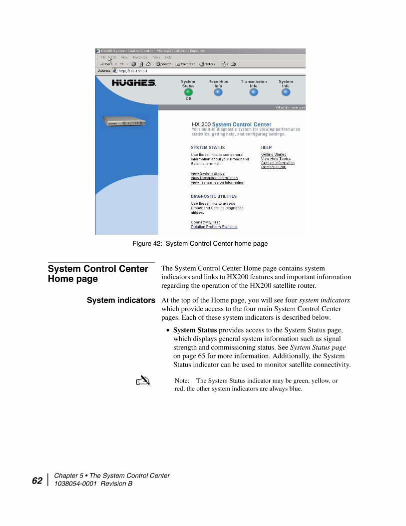
3. Press ENTER. The System Control Center home page appears as shown in Figure 42.
Note: If you are unable to access the System Control Center, refer to Cannot access the System Control Center on page 96.
Note: The computer used to browse to the System Control Center must be on the same subnet as the satellite router.
Chapter 5 • The System Control Center 1038054-0001 Revision B 61
62
System Control Center Home page
The System Control Center Home page contains system indicators and links to HX200 features and important information regarding the operation of the HX200 satellite router.
System indicators At the top of the Home page, you will see four system indicators which provide access to the four main System Control Center pages. Each of these system indicators is described below.
• System Status provides access to the System Status page, which displays general system information such as signal strength and commissioning status. See System Status page on page 65 for more information. Additionally, the System Status indicator can be used to monitor satellite connectivity.
Figure 42: System Control Center home page
Note: The System Status indicator may be green, yellow, or red; the other system indicators are always blue.
Chapter 5 • The System Control Center 1038054-0001 Revision B

If the System Status indicator is green and OK appears below it as shown in Figure 43, the satellite connection is operating properly.
If the indicator is red and Problem appears below it as shown in Figure 44, there is a problem with satellite connectivity. Click on the indicator to access the System Status page to view problem details.
If the indicator is yellow, the Web Acceleration feature may not be functioning.
• Reception Info provides access to the Reception Information page, which displays satellite router receive data. See Reception Information page on page 66 for more information.
• Transmission Info provides access to the Transmission Information page, which displays satellite router transmit data. See Transmission Information page on page 70 for more information.
• System Info provides access to the System Information page, which displays general system information such as satellite router IP address and site ID. See System Information page on page 76 for more information.
Links The System Control Center home page also contains three groups of links:
• System Status• Diagnostic Utilities• Help
Figure 43: System indicators
Figure 44: System Status indicator reporting a problem
Chapter 5 • The System Control Center 1038054-0001 Revision B 63

64
System Status The System Status links provide another means to access the System Status page, the Reception Information page, and the Transmission Information page.
Diagnostic Utilities These links allow you to perform tests and store diagnostic information. The Connectivity Test link provides access to the Connectivity Test page, which can be used to test the connection between the satellite router and the HX system gateway. See Connectivity Test page on page 78.
Help The links in the Help group provide access to various Help topics.
• Getting Started provides an overview of satellite router operation as well as access to HX200 operating instructions and recommended settings.
• View Help Topics provides access to the Help page, which offers a variety of informational topics ranging from an overview of the HX200 satellite router to answers to frequently asked questions. See Help page on page 88 for more information.
• Contact Information provides technical support and contact information. This information may vary according to service plan.
• Restart HX200 restarts the satellite router.
Chapter 5 • The System Control Center 1038054-0001 Revision B

System Status page The System Status page shown in Figure 45 displays general status information such as signal strength, receive status, transmit status, commissioning status, transmission control protocol (TCP) acceleration status, and Web acceleration status. Each of these categories is explained below.
To access the System Status page, click on the System Status indicator on the Home page.
• Signal Strength – Indicates the current strength of the receive signal.
• Receive Status – Indicates whether the receive data path is operational. Click on the status message to call up relevant Help information. For more information on receive code messages, see Receive status messages on page 67.
• Transmit Status – Indicates whether the transmit data path is operational. Click on the status message to call up relevant Help information. For more information on receive code messages, see Transmit status messages on page 70.
• Software Download Status – Indicates whether satellite router software and configuration are up-to-date. Click on the status message to call up relevant Help information
Figure 45: System Status page
Chapter 5 • The System Control Center 1038054-0001 Revision B 65

66
• Commission Status – Indicates whether the satellite router has been commissioned.
• TCP Acceleration Status – Indicates whether TCP Acceleration is operational. TCP Acceleration provides the expected performance on a satellite router.
Reception Information page
The Reception Information page shown in Figure 46 provides satellite router receive data such as receive status, number of frames received, frames that contain errors, and bad key frames. Each of these fields is explained below.
• Receive status – Reports the status of the receive data path. Click on the blue status message to display relevant Help information. Receive status messages on page 67 describes the associated RxCodes in detail.
• Frames received – Reports the number of data messages received by the satellite router over the satellite link.
• Frames with Errors – Reports the percentage of received frames that were found to be corrupt. A continuously increasing value of frames with errors is an indication that
Figure 46: Reception Information page
Chapter 5 • The System Control Center 1038054-0001 Revision B
problems exist within the receive path. This may be the result of adverse weather conditions or a problem with either the receive cable or the antenna. However; a low number of frames with errors is no reason for concern, as long as the number does not increase and the system is functioning properly.
• Bad Key Frames – All data received over the satellite is encrypted. This field indicates the percentage of received frames that could not be decrypted successfully. A continuously increasing value indicates that the satellite router has not been properly commissioned.
• Current Modcod – Indicates the current modulation and coding scheme used on the HX200 DVB-S2 outroute.
Receive status messages Table 7 lists the messages that may appear in the Receive Status field. The Corrective Actions column provides detailed information about each code and describes any possible corrective measures.
If a problem cannot be resolved by following the corrective measures, contact Technical Support.
RxCode 5 indicates that the satellite router is receiving data properly. This is the code you should see most often.
Note: The messages and associated corrective actions listed in Table 7 are current only as of this document’s release. To ensure that you have the most recent information regarding these messages, click on the blue Reception Info indicator at the top of the screen and select the Receive Status option.
Chapter 5 • The System Control Center 1038054-0001 Revision B 67
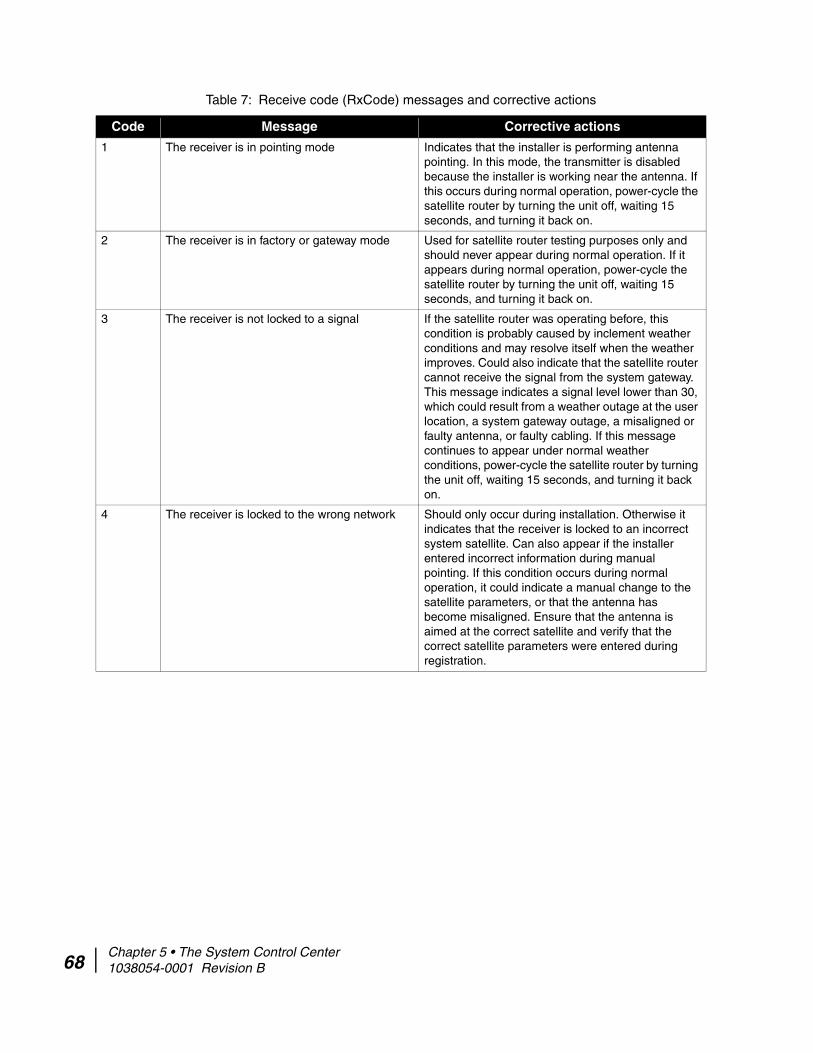
68
Table 7: Receive code (RxCode) messages and corrective actions
Code Message Corrective actions
1 The receiver is in pointing mode Indicates that the installer is performing antenna pointing. In this mode, the transmitter is disabled because the installer is working near the antenna. If this occurs during normal operation, power-cycle the satellite router by turning the unit off, waiting 15 seconds, and turning it back on.
2 The receiver is in factory or gateway mode Used for satellite router testing purposes only and should never appear during normal operation. If it appears during normal operation, power-cycle the satellite router by turning the unit off, waiting 15 seconds, and turning it back on.
3 The receiver is not locked to a signal If the satellite router was operating before, this condition is probably caused by inclement weather conditions and may resolve itself when the weather improves. Could also indicate that the satellite router cannot receive the signal from the system gateway. This message indicates a signal level lower than 30, which could result from a weather outage at the user location, a system gateway outage, a misaligned or faulty antenna, or faulty cabling. If this message continues to appear under normal weather conditions, power-cycle the satellite router by turning the unit off, waiting 15 seconds, and turning it back on.
4 The receiver is locked to the wrong network Should only occur during installation. Otherwise it indicates that the receiver is locked to an incorrect system satellite. Can also appear if the installer entered incorrect information during manual pointing. If this condition occurs during normal operation, it could indicate a manual change to the satellite parameters, or that the antenna has become misaligned. Ensure that the antenna is aimed at the correct satellite and verify that the correct satellite parameters were entered during registration.
Chapter 5 • The System Control Center 1038054-0001 Revision B

5 The receiver is operational Normal operating state for the receiver. Indicates that data is being received from the system gateway. The transmitter will only operate correctly when the receiver is in this state.
6 The receiver is not detecting a signal Occurs when the unit is not detecting a radio signal from the antenna. May indicate a faulty receiver or faulty cabling between the receiver and the antenna. Check that the cables are firmly connected to the satellite router. (See the Caution statement that follows Figure 2 on page 13.) If this condition persists, power-cycle the satellite router by turning the unit off, waiting 15 seconds, and turning it back on.
7 The receiver is locked to an unknown network Should only occur during installation or when the receiver is locked to a non-system satellite. In rare cases, may also be due to a transient outage at the system gateway. If this condition occurs during pointing or commissioning, the antenna has not been pointed correctly. If it occurs during normal operation, could indicate a change in satellite parameters, or that the antenna has become misaligned. If the satellite parameters have been changed, re-commission the site. Otherwise, repoint the antenna.
Table 7: Receive code (RxCode) messages and corrective actions (Continued)
Code Message Corrective actions
Chapter 5 • The System Control Center 1038054-0001 Revision B 69

70
Transmission Information page
The Transmission Information page shown in Figure 47 displays satellite router transmit data such as transmit status, the number of packets submitted for transmission, the number of successful transmissions, and the number of failed transmissions. Each of these fields is described below.
• Transmit status –- Provides the status of the transmit data path. Click on the blue status message to display relevant Help information. Transmit status messages on page 70 describes the associated TxCodes in detail.
• Number of successful transmissions –- Reports the number of frames transmitted to the satellite.
• Number of failed transmissions –- Reports the number of frames that could not be sent. A continuously increasing value indicates a transmit problem. However; a low number of failed transmissions is no reason for concern, as long as the number does not increase and the system is functioning properly.
• Number of packets submitted for transmission – Indicates the total amount of data queued for transmission to the satellite.
Transmit status messages Table 8 lists messages that may appear in the Transmit field. The Corrective Actions column provides detailed information about each code and describes any possible corrective measures.
Figure 47: Transmission Information page
Chapter 5 • The System Control Center 1038054-0001 Revision B
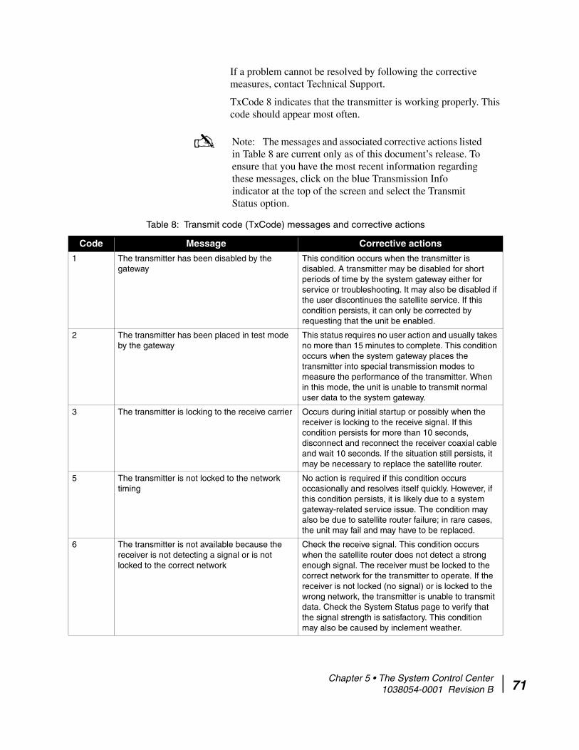
If a problem cannot be resolved by following the corrective measures, contact Technical Support.
TxCode 8 indicates that the transmitter is working properly. This code should appear most often.
Note: The messages and associated corrective actions listed in Table 8 are current only as of this document’s release. To ensure that you have the most recent information regarding these messages, click on the blue Transmission Info indicator at the top of the screen and select the Transmit Status option.
Table 8: Transmit code (TxCode) messages and corrective actions
Code Message Corrective actions
1 The transmitter has been disabled by the gateway
This condition occurs when the transmitter is disabled. A transmitter may be disabled for short periods of time by the system gateway either for service or troubleshooting. It may also be disabled if the user discontinues the satellite service. If this condition persists, it can only be corrected by requesting that the unit be enabled.
2 The transmitter has been placed in test mode by the gateway
This status requires no user action and usually takes no more than 15 minutes to complete. This condition occurs when the system gateway places the transmitter into special transmission modes to measure the performance of the transmitter. When in this mode, the unit is unable to transmit normal user data to the system gateway.
3 The transmitter is locking to the receive carrier Occurs during initial startup or possibly when the receiver is locking to the receive signal. If this condition persists for more than 10 seconds, disconnect and reconnect the receiver coaxial cable and wait 10 seconds. If the situation still persists, it may be necessary to replace the satellite router.
5 The transmitter is not locked to the network timing
No action is required if this condition occurs occasionally and resolves itself quickly. However, if this condition persists, it is likely due to a system gateway-related service issue. The condition may also be due to satellite router failure; in rare cases, the unit may fail and may have to be replaced.
6 The transmitter is not available because the receiver is not detecting a signal or is not locked to the correct network
Check the receive signal. This condition occurs when the satellite router does not detect a strong enough signal. The receiver must be locked to the correct network for the transmitter to operate. If the receiver is not locked (no signal) or is locked to the wrong network, the transmitter is unable to transmit data. Check the System Status page to verify that the signal strength is satisfactory. This condition may also be caused by inclement weather.
Chapter 5 • The System Control Center 1038054-0001 Revision B 71
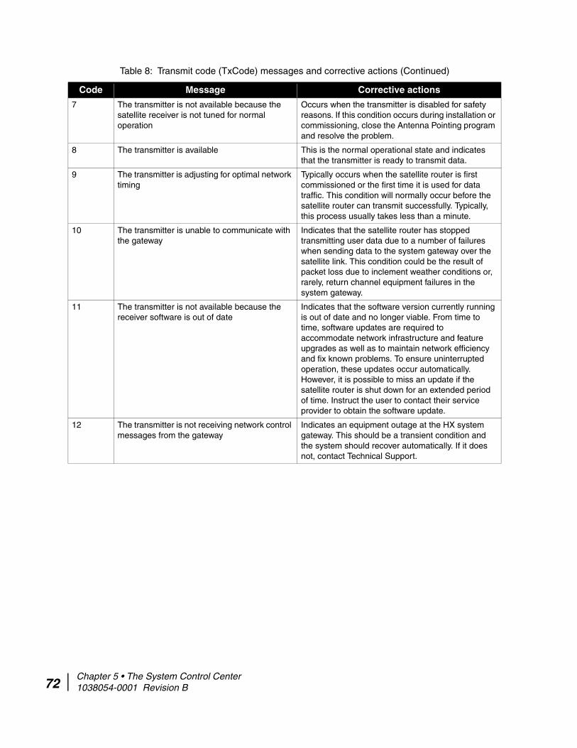
72
7 The transmitter is not available because the satellite receiver is not tuned for normal operation
Occurs when the transmitter is disabled for safety reasons. If this condition occurs during installation or commissioning, close the Antenna Pointing program and resolve the problem.
8 The transmitter is available This is the normal operational state and indicates that the transmitter is ready to transmit data.
9 The transmitter is adjusting for optimal network timing
Typically occurs when the satellite router is first commissioned or the first time it is used for data traffic. This condition will normally occur before the satellite router can transmit successfully. Typically, this process usually takes less than a minute.
10 The transmitter is unable to communicate with the gateway
Indicates that the satellite router has stopped transmitting user data due to a number of failures when sending data to the system gateway over the satellite link. This condition could be the result of packet loss due to inclement weather conditions or, rarely, return channel equipment failures in the system gateway.
11 The transmitter is not available because the receiver software is out of date
Indicates that the software version currently running is out of date and no longer viable. From time to time, software updates are required to accommodate network infrastructure and feature upgrades as well as to maintain network efficiency and fix known problems. To ensure uninterrupted operation, these updates occur automatically. However, it is possible to miss an update if the satellite router is shut down for an extended period of time. Instruct the user to contact their service provider to obtain the software update.
12 The transmitter is not receiving network control messages from the gateway
Indicates an equipment outage at the HX system gateway. This should be a transient condition and the system should recover automatically. If it does not, contact Technical Support.
Table 8: Transmit code (TxCode) messages and corrective actions (Continued)
Code Message Corrective actions
Chapter 5 • The System Control Center 1038054-0001 Revision B

13 The transmitter is unable to range because it cannot communicate with the gateway
Ranging is the automated process of adjusting satellite transmitter timing and power. The satellite transmitter performs ranging as necessary to ensure that it can communicate successfully with the HX system gateway. This condition can indicate any of the following:• The system gateway is not receiving ranging
information from the transmitter. This may indicate a problem at the gateway and should resolve itself within a few minutes.
• The transmitter is unable to achieve enough power to send ranging information to the system gateway.
• The transmitter is sending incorrect timing data because incorrect latitude/longitude information was entered during installation.
• The outdoor transmitter unit (ODU) is not operating properly or is not properly connected to the satellite router. Ensure that the transmit cable is securely fastened to the TRANSMIT connector.
(See the Caution statement that follows Figure 2 on page 13.)
14 The transmitter is not available because ranging has failed
Indicates that the transmitter is not operational due to a ranging failure. Ranging is the automated process of adjusting satellite transmitter timing and power. The satellite transmitter performs ranging as necessary to ensure that it can communicate successfully with the system gateway. A ranging failure may occur due to antenna misalignment or after several failed ranging attempts. Realign the antenna as necessary. This condition may also be caused by adverse weather conditions. In rare cases, this condition may also indicate system gateway issues but, in such cases, should clear within a few minutes. For repeated messages of this type on a system that was previously operational, try to force ranging by performing the Connectivity Test.
15 The transmitter is waiting for a ranging request to be processed by the gateway
Occurs when the system is busy adjusting power and timing for other users. This process may take up to a minute or more.
16 The transmitter is waiting for a transmit request to be processed by the gateway
Occurs when the system is unable to provide transmit bandwidth due to a large number of users signing on simultaneously. This condition should clear itself within a few minutes.
Table 8: Transmit code (TxCode) messages and corrective actions (Continued)
Code Message Corrective actions
Chapter 5 • The System Control Center 1038054-0001 Revision B 73

74
17 The satellite transmitter is unable to obtain an available transmission rate
Occurs if the transmitter is unable to range successfully. Ranging is the automated process of adjusting the satellite transmitter timing and power. The satellite transmitter performs ranging as necessary to ensure that it can communicate successfully with the gateway. This condition may be caused by incorrect bit rate mask usage or if the transmitter in unable to generate enough power to enable it to transmit, most likely because the antenna is not accurately pointed. However, it may also be problem with the transmitter power supply. Repoint the antenna. If the problem persists, check the power supply.
18 The transmitter is requesting a transmit pointing test
Occurs during initial installation when the Antenna Pointing program requests that the transmitter perform a transmit pointing test. This condition will continue until the system gateway responds that the transmitter is either actively performing the test or is queued to perform the test when gateway test resources become available. The transmitter may also report this condition for short periods of time (less than 5 seconds) when performing periodic transmit pointing tests during normal operation. No action is required.
19 The transmitter is queued for a transmit pointing test
May occur during initial installation after the Antenna Pointing program requests that the transmitter perform a transmit pointing test and the system gateway responds that the transmitter is queued for the next available test time. It may also occur when the transmitter is performing periodic background transmit pointing tests at the same time as other users on the network have requested tests. This is a normal state after initial installation.
20 The transmitter is performing a transmit pointing test
Occurs when one of the following tests are active:• During installation, the Antenna Pointing software
requests that the transmitter performs a transmit pointing test. This condition will continue until the test is concluded and the Antenna Pointing software returns to normal operating mode.
• The satellite router performs a periodic background transmit pointing test to make sure that the antenna is still pointed correctly. This periodic test takes less than 5 seconds.
If this condition persists, power-cycle the satellite router by turning the unit off, waiting 15 seconds, and turning it back on.
Table 8: Transmit code (TxCode) messages and corrective actions (Continued)
Code Message Corrective actions
Chapter 5 • The System Control Center 1038054-0001 Revision B

21 The transmitter is disabled because a transmit pointing test failed
Occurs when the transmitter fails a transmit pointing test, thereby indicating that the transmitter did not meet the minimum specifications required. This is likely due to an antenna installation problem. Fine-point the antenna. The transmitter will not transmit until the transmit pointing test passes.
22 The transmitter is disabled pending a transmit pointing test
Occurs when the transmitter is unable to perform a periodic background transmit pointing test within the allotted time frame. The transmitter is expected to be in this condition at random periodic intervals for no more than two minutes at a time. This condition can also occur after the transmitter is first powered on after it has been powered off for more than a 24 hours. If this condition persists for more than two minutes, it is likely that the automated transmit pointing components in the system gateway are experiencing problems. This condition should clear in a few minutes.
23 The transmitter is disabled because a transmit pointing test cannot be performed
Occurs when the transmitter cannot perform a transmit pointing test during initial installation or when ranging. Ranging is the automated process of adjusting the satellite transmitter timing and power. The satellite transmitter performs ranging as necessary to ensure that it can communicate successfully with the system gateway. The condition indicates that the system gateway components required to perform the transmit pointing test are not operational.
24 The transmit cable is disconnected Indicates that the satellite router unit cannot detect the transmit cable connection. Ensure that the transmit cable is securely attached to the satellite router unit and to the transmitter on the antenna assembly. (See the Caution statement that follows Figure 2 on page 13.) Inspect the transmit cable and the antenna assembly to make sure that they are not damaged.
25 Uplink reset is in progress This is a transitional state and requires no interaction. If the problem persists, contact Technical Support.
26 No inroute groups support Closed Loop timing Indicates a problem at the HX System Gateway. If the problem persists, contact Technical Support.
Table 8: Transmit code (TxCode) messages and corrective actions (Continued)
Code Message Corrective actions
Chapter 5 • The System Control Center 1038054-0001 Revision B 75
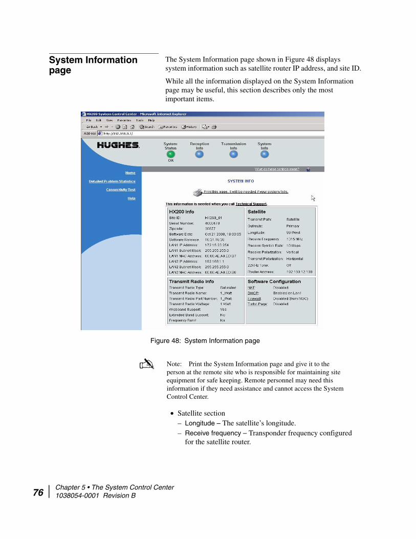
76
System Information page
The System Information page shown in Figure 48 displays system information such as satellite router IP address, and site ID.
While all the information displayed on the System Information page may be useful, this section describes only the most important items.
• Satellite section– Longitude – The satellite’s longitude.– Receive frequency – Transponder frequency configured
for the satellite router.
Figure 48: System Information page
Note: Print the System Information page and give it to the person at the remote site who is responsible for maintaining site equipment for safe keeping. Remote personnel may need this information if they need assistance and cannot access the System Control Center.
Chapter 5 • The System Control Center 1038054-0001 Revision B

– Receive Polarization – Polarization orientation; either horizontal or vertical.
– Router Address – IP address of the primary system gateway router used to route data sent by the satellite router.
• Software Configuration section – Network address translation (NAT), DHCP, and firewall features are enabled or disabled at the system gateway per site requirements and cannot be changed by remote users.
– Network Address Translation (NAT) – Typically used to allow multiple computers to share a single address on the Internet, also allows pre-configured remote networks to be integrated easily with the system network.
– Dynamic Host Configuration Protocol (DHCP) – If enabled, simplifies network configuration of the computers. The computers need only to be set up to “Obtain IP address automatically.”
– Turbo Page – An optional feature; enabled if the HX gateway is configured for Web Acceleration.
– Firewall – If enabled, implements firewall rules and related policies. Firewall rules are configured on the system gateway in satellite router profiles.
• Transmit Radio Info– Transmit radio type– Transmit radio name– Part number– Transmit radio wattage– Wideband support– Extended band support– Frequency band
Chapter 5 • The System Control Center 1038054-0001 Revision B 77

78
Connectivity Test page The Connectivity Test page shown in Figure 49 may be used to test the connection between the satellite router and the system gateway. Instructions for executing a connectivity test are provided in Checking system gateway connectivity on page 100.
Optional Features Pages
The HX200 satellite router has two optional features that, once enabled at the NOC, allow the operator to configure at the System Control Center.
The optional features are:
• Firewall• Port Forwarding
The links to the configuration screens related to these features appear in the left area of the main pages.
A screen for viewing firewall statistics is also available when the firewall option is enabled. Note that the port forwarding option can only be configured when network address port translation (NAPT) has been enabled for the HX200 at the HX system gateway.
Firewall Configuration page When remote firewall configuration for a satellite router is allowed at the system gateway, links for viewing Firewall Configuration and Firewall Statistics pages appear in the
Figure 49: Connectivity Test page
Chapter 5 • The System Control Center 1038054-0001 Revision B

navigation area of the four main System Control Center pages. The Firewall Configuration link opens the Firewall Configuration page shown in Figure 50.
Figure 50: Firewall configuration page
Chapter 5 • The System Control Center 1038054-0001 Revision B 79

80
Understanding how the firewall works
The Firewall Configuration page provides controls for creating and managing firewall rules. The firewall feature provides firewall protection for the computers connected to the HX200. The firewall rules that you create apply only to inbound traffic; that is, network traffic sent from the HX system gateway to the satellite router.
Think of firewall rules as templates against which network packets received from the system gateway are compared. When a packet matches the value or values defined in a rule, the rule action is applied to the packet. For example, if you:
• create a firewall rule that matches all traffic targeted to port 22 (that is, traffic from any source IP address to any destination IP address with a destination port of 22), and
• define the rule action as BLOCKED, then packets with a destination port number of 22 addressed to any IP device behind the satellite router will be dropped.
Traffic is matched against firewall rules in the order that the rules are listed in the firewall rule table. The action of the first matching firewall rule is applied; no further matching is attempted after the first successful match.
Firewall rule restrictions
The following restrictions apply to firewall rules:
• The number of rules is limited to 20• The number of ports defined in the Source Port and
Destination Port fields is limited to 5 individually enumerated ports. Entering a port range is not supported.
• Rules are applied in the order listed in the firewall rule list. The rules cannot be reordered without deleting and recreating them.
• If ICMP is selected as the Protocol Type, all ICMP packets (ICMP Type 255) are filtered.
If the Protocol Type is set to either TCP or UDP, a minimum of one port number must be defined in either the Source or Destination Port Number fields.
Creating firewall rules To create firewall rules:
1. Click the Firewall Configuration link in the System Control Center navigation area.The Firewall Configuration page appears.
2. Click Add Rule.
Chapter 5 • The System Control Center 1038054-0001 Revision B
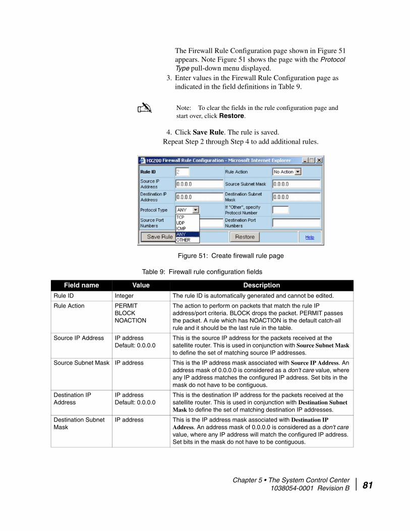
The Firewall Rule Configuration page shown in Figure 51 appears. Note Figure 51 shows the page with the Protocol Type pull-down menu displayed.
3. Enter values in the Firewall Rule Configuration page as indicated in the field definitions in Table 9.
4. Click Save Rule. The rule is saved.Repeat Step 2 through Step 4 to add additional rules.
Note: To clear the fields in the rule configuration page and start over, click Restore.
Figure 51: Create firewall rule page
Table 9: Firewall rule configuration fields
Field name Value Description
Rule ID Integer The rule ID is automatically generated and cannot be edited.
Rule Action PERMITBLOCKNOACTION
The action to perform on packets that match the rule IP address/port criteria. BLOCK drops the packet. PERMIT passes the packet. A rule which has NOACTION is the default catch-all rule and it should be the last rule in the table.
Source IP Address IP addressDefault: 0.0.0.0
This is the source IP address for the packets received at the satellite router. This is used in conjunction with Source Subnet Mask to define the set of matching source IP addresses.
Source Subnet Mask IP address This is the IP address mask associated with Source IP Address. An address mask of 0.0.0.0 is considered as a don't care value, where any IP address matches the configured IP address. Set bits in the mask do not have to be contiguous.
Destination IP Address
IP addressDefault: 0.0.0.0
This is the destination IP address for the packets received at the satellite router. This is used in conjunction with Destination Subnet Mask to define the set of matching destination IP addresses.
Destination Subnet Mask
IP address This is the IP address mask associated with Destination IP Address. An address mask of 0.0.0.0 is considered as a don't care value, where any IP address will match the configured IP address. Set bits in the mask do not have to be contiguous.
Chapter 5 • The System Control Center 1038054-0001 Revision B 81

82
Modifying and deleting firewall rules
You can modify or delete firewall rules at the Firewall Configuration page. To modify or delete a firewall rule:
1. Click the Modify/Delete link in the leftmost column of a firewall rule.The Firewall Rule Configuration page appears, as shown in Figure 52, with the rule values displayed in the fields. Note that Figure 52 shows the page with the Rule Action pull-down menu displayed.
2. To modify a rule, change the values in one or more of the fields, then click Save Rule.
3. To delete a rule, click Delete Rule.
Protocol Type TCPUDPICMPANYOTHER
This is the Protocol that is encapsulated in the IP packet. A value of OTHER indicates the value in the If “Other”, specify Protocol Number field should be used.
Source Port Numbers
One or more comma-separated Integer values.
Up to 5 port numbers separated by commas. If the Protocol Type is TCP or UDP, you must enter at least one port number in this field or the Destination Port Number field.
Destination Port Numbers
One or more comma-separated Integer values.
Up to 5 port numbers separated by commas may be entered. Only enter port numbers if Protocol Type is TCP or UDP.
Table 9: Firewall rule configuration fields (Continued)
Field name Value Description
Figure 52: Modify/delete firewall rule page
Chapter 5 • The System Control Center 1038054-0001 Revision B

Enabling and disabling the firewall
Once firewall rules have been created, you can enable the firewall. You can also disable the firewall at any time.
• To enable the firewall, select the Enable Firewall checkbox located in the upper left corner of the firewall rule list, then click Submit.
• To disable the firewall, clear the Enable Firewall checkbox located in the upper left corner of the firewall rule list, then click Submit.
The Firewall Statistics page The Firewall Statistics page shows:
• The firewall status (enabled or disabled)• The number of packets processed by the firewall• The number of packets discarded by the firewall • The number of packets discarded by each firewall rule
The three packet-count statistics are the number counted since the last time the Clear Counters button was clicked.
Chapter 5 • The System Control Center 1038054-0001 Revision B 83

84
Viewing firewall statistics To view the Firewall Statistics page, click the Firewall Statistics link in the navigation area on the left-hand side of the System Control Center page. The Firewall Statistics page shown in Figure 53 appears.
Resetting firewall statistics counters
To reset the firewall statistics counters to zero, click Clear Counters.
Figure 53: Firewall Statistics page
Chapter 5 • The System Control Center 1038054-0001 Revision B

Port Forwarding Configuration page
If an HX200 is connected to a system gateway that has NAPT enabled, and the satellite router is configured at the system gateway to allow local port forwarding control, a Port Forwarding Configuration link will appear in the navigation area on the left side of the System Control Center page. Clicking the link opens the Port Forwarding Configuration page shown in Figure 54, where you can create port forwarding rules.
Understanding port forwarding NAPT, also called port address translation, or PAT, assigns private (non-routable) Internet addresses to computers on the LAN connected to the HX200. The HX200 IP address is used as the source address for all network traffic coming from the remote LAN, thus making it impossible for computers on the enterprise network behind the system gateway to directly address packets to, and communicate directly with, computers on the remote LAN.
The port forwarding feature provides a means for this communication to occur by mapping a port number to the IP address of a computer on the remote LAN. Computers behind the system gateway can address traffic to the HX200 IP address and this port number and the traffic will be forwarded to the IP address on the remote LAN associated with the port number.
Figure 54: Port Forwarding Configuration page
Chapter 5 • The System Control Center 1038054-0001 Revision B 85

86
The port forwarding feature also translates the port number in received traffic before sending it to its destination by replacing the received destination port value with a different one.
Port forwarding is configured using port forwarding rules. Controls for creating, modifying, and deleting port forwarding rules are provided. The rules are applied by matching the protocol type and destination port number in inbound packets (packets received from the HX system gateway) against the protocol type/port defined in the rules. If a packet matches, the port number in the packet header is rewritten with the port number defined in the rule and the packet is forwarded to the IP address defined in the rule.
Port forwarding rule restrictions
A maximum of 20 port forwarding rules can be created.
Creating port forwarding rules To create port forwarding rules:
1. Click the Port Forwarding Configuration link in the System Control Center navigation area.The Port Forwarding Configuration page appears.
2. Click Add Rule.The port forwarding rule configuration page shown in Figure 55 appears.
3. In the Server IP Address field, enter the IP address of the computer on the remote LAN to which traffic will be port-forwarded.
4. In the Server port field, enter the destination port number that should be used to replace the Global port value in matching packets before sending them to the remote LAN.
5. In the Global port field, enter the port number to match against inbound traffic from the HX system gateway. The
Figure 55: Create port forwarding rule page
Note: To clear the fields in the rule configuration page and start over, click Restore.
Chapter 5 • The System Control Center 1038054-0001 Revision B
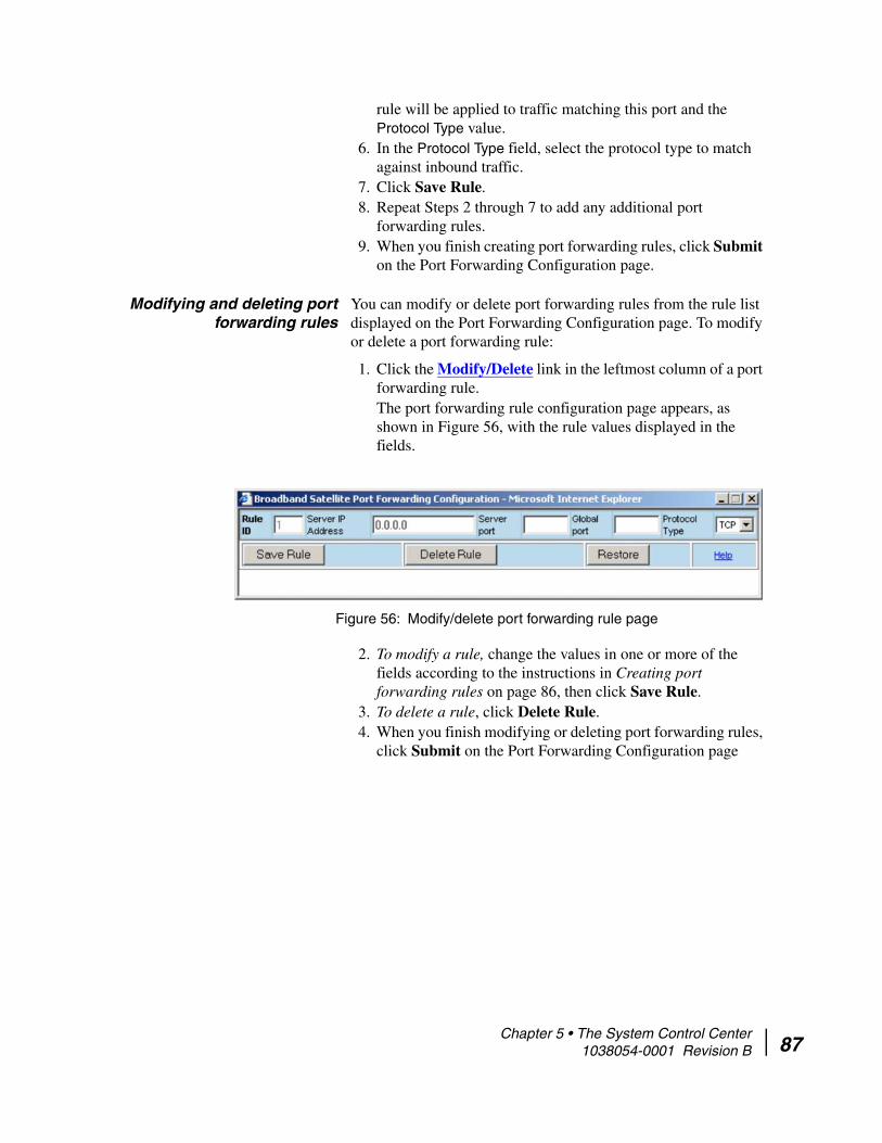
rule will be applied to traffic matching this port and the Protocol Type value.
6. In the Protocol Type field, select the protocol type to match against inbound traffic.
7. Click Save Rule.8. Repeat Steps 2 through 7 to add any additional port
forwarding rules.9. When you finish creating port forwarding rules, click Submit
on the Port Forwarding Configuration page.
Modifying and deleting port forwarding rules
You can modify or delete port forwarding rules from the rule list displayed on the Port Forwarding Configuration page. To modify or delete a port forwarding rule:
1. Click the Modify/Delete link in the leftmost column of a port forwarding rule.The port forwarding rule configuration page appears, as shown in Figure 56, with the rule values displayed in the fields.
2. To modify a rule, change the values in one or more of the fields according to the instructions in Creating port forwarding rules on page 86, then click Save Rule.
3. To delete a rule, click Delete Rule.4. When you finish modifying or deleting port forwarding rules,
click Submit on the Port Forwarding Configuration page
Figure 56: Modify/delete port forwarding rule page
Chapter 5 • The System Control Center 1038054-0001 Revision B 87
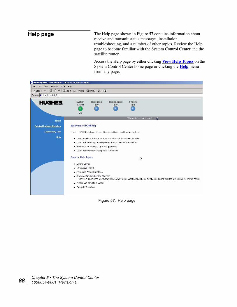
88
Help page The Help page shown in Figure 57 contains information about receive and transmit status messages, installation, troubleshooting, and a number of other topics. Review the Help page to become familiar with the System Control Center and the satellite router.
Access the Help page by either clicking View Help Topics on the System Control Center home page or clicking the Help menu from any page.
Figure 57: Help page
Chapter 5 • The System Control Center 1038054-0001 Revision B

Advanced pages The Advanced pages contain a great deal of information. You may need to access this information to communicate with Technical Support or to configure special features.
To access the Advanced pages, in the browser address bar type:
192.168.0.1/fs/advanced/advanced.html and press ENTER. The Advanced Configuration and Statistics page appears as shown in Figure 58.
Note: The Advanced pages provide access to critical configuration parameters and other functions. Do not use these pages unless you are a qualified technician who thoroughly understands how the satellite router operates or unless a Technical Support representative instructs you to access the Advanced pages for troubleshooting purposes.
Figure 58: Advanced page
Chapter 5 • The System Control Center 1038054-0001 Revision B 89

90
Chapter 5 • The System Control Center 1038054-0001 Revision B
Chapter 6
TroubleshootingThis chapter provides general troubleshooting procedures, including how to use the HX200 satellite router light-emitting diodes (LEDs) to troubleshoot problems with the unit.
HX200 LEDs As shown in Figure 59, the HX200 has five LED indicators on its front panel that can be used for troubleshooting and fault isolation. If you cannot access the System Control Center, use the front panel LEDs to troubleshoot by following the procedures in this section in sequence.
The functions of the LED indicators are:
• Transmit – The Transmit indicator shows whether the satellite router can transmit or is transmitting, or if some condition is preventing transmission.
• Receive – The Receive indicator shows whether the satellite router has acquired the correct outroute, is receiving, or if some condition is preventing reception.
• Power – The Power indicator shows whether or not the HX200 is powered on and operating normally.
Figure 59: Satellite router LEDs
Chapter 6 • Troubleshooting 1038054-0001 Revision B 91

92
• System – The System indicator shows whether or not the HX200 is operational.
• LAN – The LAN indicator shows whether the LAN is connected and usable, and whether there is receive or transmit activity.
LED appearances during normal operation
This section describes the appearance of the HX200 LEDs during normal satellite router operation.
When the satellite router is powered on and transmitting or receiving data or receiving data:
• The Transmit LED is on and blinks intermittently as frames are transmitted.
• The Receive LED is on and blinks intermittently as frames are received.
• The Power LED is on.• The System LED is on.• The LAN LED is on and blinks intermittently as packets are
transmitted or received.
Table 10 provides additional information about the LEDs and what they indicate when they are on, off, blinking, or flashing. (Blinking means the LED is usually on, but intermittently turns off briefly. Flashing means the LED alternates between on and off for periods of 1/2 sec to 1 sec.) The table also suggests appropriate troubleshooting steps for each situation.
CAUTIONDo not power cycle the satellite router by unplugging the power cord from the back of the router. This could shock you and/or damage the satellite router.
Chapter 6 • Troubleshooting 1038054-0001 Revision B

Table 10: Satellite router front panel LED operation
LED Appearance Description
Transmit On OK.
Blinking, mostly on Transmitting data.
Blinking, mostly off The satellite router is ranging (measuring the distance to the satellite to calibrate transmit timing and transmit power).
Off Condition preventing transmission.If the HX200 is not operating normally and the receive LED is off, follow these steps:1. Check all cable connections and tighten any connections that seem loose.(See the Caution statement that follows Figure 2 on page 13.)2. If the LED still does not light up, power cycle the satellite router by turning it off using the power switch on the rear panel, waiting 10 seconds, and then turning it back on.3. If the problem persists, contact Technical Support.
Receive On OK.
Blinking Receiving data.
Off Condition preventing acquisition of outroute (preventing receipt of data).If the HX200 is not operating normally and the receive LED is off, follow these steps:1. Check all cable connections and tighten any connections that seem loose.(See the Caution statement that follows Figure 2 on page 13.)2. If the LED still does not light up, power cycle the satellite router by turning it off using the power switch on the rear panel, waiting 10 seconds, and then turning it back on.3. If the problem persists, contact Technical Support.Note: Often, if the Receive LED is off, the other LEDs may also be off.
Chapter 6 • Troubleshooting 1038054-0001 Revision B 93
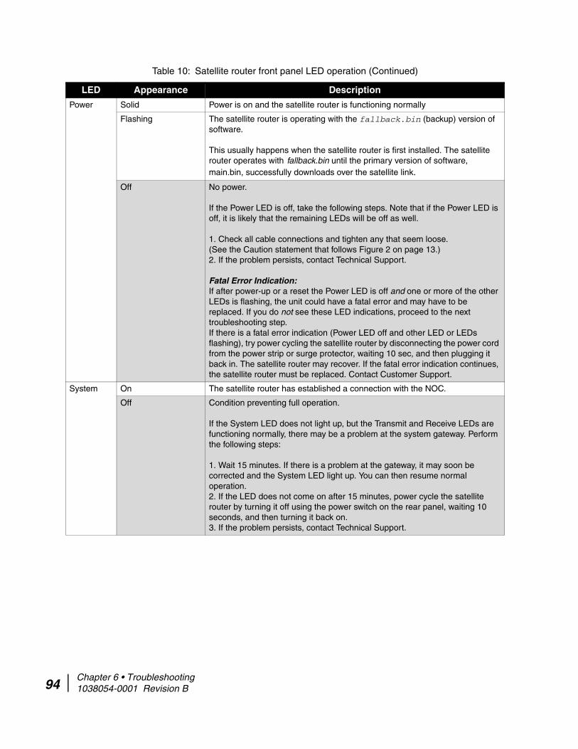
94
Power Solid Power is on and the satellite router is functioning normally
Flashing The satellite router is operating with the fallback.bin (backup) version of software.
This usually happens when the satellite router is first installed. The satellite router operates with fallback.bin until the primary version of software, main.bin, successfully downloads over the satellite link.
Off No power.
If the Power LED is off, take the following steps. Note that if the Power LED is off, it is likely that the remaining LEDs will be off as well.
1. Check all cable connections and tighten any that seem loose.(See the Caution statement that follows Figure 2 on page 13.)2. If the problem persists, contact Technical Support.
Fatal Error Indication: If after power-up or a reset the Power LED is off and one or more of the other LEDs is flashing, the unit could have a fatal error and may have to be replaced. If you do not see these LED indications, proceed to the next troubleshooting step.If there is a fatal error indication (Power LED off and other LED or LEDs flashing), try power cycling the satellite router by disconnecting the power cord from the power strip or surge protector, waiting 10 sec, and then plugging it back in. The satellite router may recover. If the fatal error indication continues, the satellite router must be replaced. Contact Customer Support.
System On The satellite router has established a connection with the NOC.
Off Condition preventing full operation.
If the System LED does not light up, but the Transmit and Receive LEDs are functioning normally, there may be a problem at the system gateway. Perform the following steps:
1. Wait 15 minutes. If there is a problem at the gateway, it may soon be corrected and the System LED light up. You can then resume normal operation.2. If the LED does not come on after 15 minutes, power cycle the satellite router by turning it off using the power switch on the rear panel, waiting 10 seconds, and then turning it back on.3. If the problem persists, contact Technical Support.
Table 10: Satellite router front panel LED operation (Continued)
LED Appearance Description
Chapter 6 • Troubleshooting 1038054-0001 Revision B
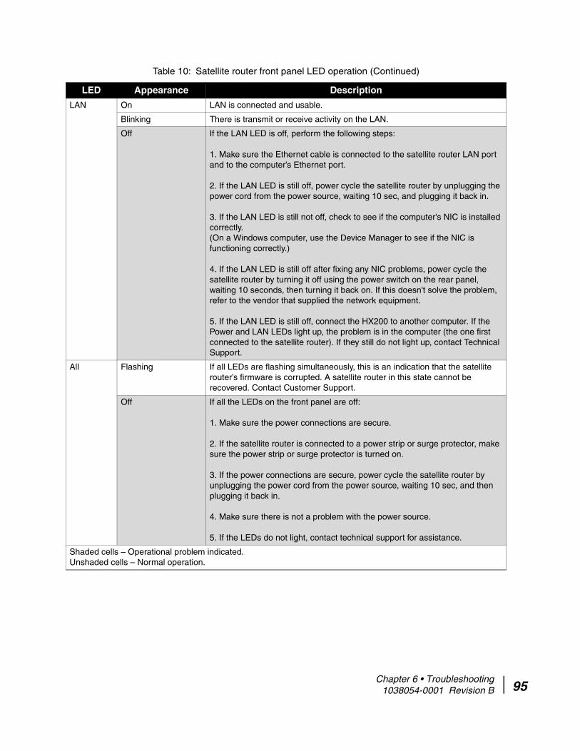
LAN On LAN is connected and usable.
Blinking There is transmit or receive activity on the LAN.
Off If the LAN LED is off, perform the following steps:
1. Make sure the Ethernet cable is connected to the satellite router LAN port and to the computer’s Ethernet port.
2. If the LAN LED is still off, power cycle the satellite router by unplugging the power cord from the power source, waiting 10 sec, and plugging it back in.
3. If the LAN LED is still not off, check to see if the computer's NIC is installed correctly. (On a Windows computer, use the Device Manager to see if the NIC is functioning correctly.)
4. If the LAN LED is still off after fixing any NIC problems, power cycle the satellite router by turning it off using the power switch on the rear panel, waiting 10 seconds, then turning it back on. If this doesn't solve the problem, refer to the vendor that supplied the network equipment.
5. If the LAN LED is still off, connect the HX200 to another computer. If the Power and LAN LEDs light up, the problem is in the computer (the one first connected to the satellite router). If they still do not light up, contact Technical Support.
All Flashing If all LEDs are flashing simultaneously, this is an indication that the satellite router’s firmware is corrupted. A satellite router in this state cannot be recovered. Contact Customer Support.
Off If all the LEDs on the front panel are off:
1. Make sure the power connections are secure.
2. If the satellite router is connected to a power strip or surge protector, make sure the power strip or surge protector is turned on.
3. If the power connections are secure, power cycle the satellite router by unplugging the power cord from the power source, waiting 10 sec, and then plugging it back in.
4. Make sure there is not a problem with the power source.
5. If the LEDs do not light, contact technical support for assistance.
Shaded cells – Operational problem indicated. Unshaded cells – Normal operation.
Table 10: Satellite router front panel LED operation (Continued)
LED Appearance Description
Chapter 6 • Troubleshooting 1038054-0001 Revision B 95

96
Connectivity problems When troubleshooting connectivity problems, start with these steps:
1. Connect the Ethernet port of the computer you will use for troubleshooting directly to the HX200 LAN1 port (or whichever LAN port on the unit has an assigned IP address, as indicated on the System Control Center System Information screen), bypassing any network equipment at the remote site.
2. On the computer connected to the HX200, disable firewall, intrusion detection/prevention, or any other software designed to block or alter network traffic.
3. If the satellite router has firewall rules configured that can be edited on the satellite router, disable the firewall as explained in Enabling and disabling the firewall on page 83.
4. Retest to confirm that the problem still exists.
If the problem persists, proceed with the remaining troubleshooting steps in this chapter.
Cannot access the System Control Center
If you cannot access the System Control Center, refer to the appropriate troubleshooting procedure for the hardware configuration:
• Computer is connected directly to the satellite router• Satellite router is connected to an Ethernet device
Computer is connected directly to the satellite
router
Follow the steps below if the computer is connected directly to the satellite router. If you complete a step and the System Control Center does not appear, continue with the next step. Repeat the steps once more before contacting Technical Support.
1. Make sure that the HX200 is powered up by checking the front panel LEDs. The Power and LAN LEDs should be steadily on.
2. Open a web browser.3. Type 192.168.0.1 in the browser address field or, if an
alternate IP address was assigned to the satellite router at the HX system gateway, use that IP address instead. Press ENTER.
4. If you are still unable to access the System Control Center, continue with HX200 LEDs on page 91.
Note: If there is LAN activity, the LAN LED may be blinking.
Chapter 6 • Troubleshooting 1038054-0001 Revision B

Satellite router is connected to an Ethernet device
Follow the steps below if the satellite router is connected to an Ethernet device such as a router or a wireless base station:
1. Disconnect the Ethernet cable from the HX200 satellite router and connect it to the Ethernet port on the computer.
2. Restart the computer.3. Make sure that the HX200 satellite router is powered up by
checking the front panel LEDs. The Power and LAN LEDs should be steadily on.
4. Open a web browser.5. Type 192.168.0.1 in the browser address field or, if an
alternate IP address was assigned to the satellite router at the HX system gateway, use that IP address instead. Press ENTER.
If you are able to access the System Control Center after connecting the HX200 directly to the computer, the Ethernet device may not be configured properly. Refer to the Ethernet device documentation for instructions on how to configure it properly. Make sure to reconnect the HX200 to the Ethernet device before attempting to access the System Control Center again.
If you are still unable to access the System Control Center, continue with HX200 LEDs on page 91.
Cannot access network resources
Use the procedures in this section to troubleshoot problems reaching the enterprise network behind the HX system gateway, characterized by an inability to use enterprise services.
If you can access the System Control Center but are unable to reach the enterprise network—for instance, if you are unable to ping enterprise DNS servers that should be reachable behind the system gateway, complete the troubleshooting procedures in this section in sequence. If, after completing these procedures, the problem persists, contact Technical Support for assistance.
Note: If there is LAN activity, the LAN LED may be blinking.
Chapter 6 • Troubleshooting 1038054-0001 Revision B 97
98
Accessing the System Control Center
Access the HX200 System Control Center by opening a web browser on a computer connected to the HX200 and using one of the following methods:
• Type 192.168.0.1 in the browser address field, or if an alternate IP address was assigned to the HX200 at the system gateway, use that IP address instead.
• Press ENTER.
Confirming that the satellite router is commissioned
Follow these steps to confirm that the HX200 satellite router has been properly commissioned:
1. Navigate to the System Control Center System Information page.
2. In the area labeled HX200 Info, check the Site ID field. If the numeric site ID appears, the HX200 has been commissioned properly. Proceed to Checking the receive signal.If the phrase Not Commissioned appears, an error occurred during the commissioning process. Recommission the satellite router.
Checking the receive signal Follow these steps to confirm that the HX200 is receiving satellite signals properly:
1. Navigate to the System Control Center Reception Information page.
2. In the Receive Status field, check the Rx Code.If the Rx Code reads Receiver operational (RxCode 5), the satellite router is receiving signals properly. Proceed to Checking the transmit signal. If any other Rx Code appears, the satellite router is not receiving signals properly. Click on the Rx Code and follow the troubleshooting procedures that appear on the screen.
Weather and signal strength Heavy rain or snow can interfere with signal strength. In such conditions, the satellite router may stop receiving satellite signals, and the Receive LED may go out as a result. Similar conditions at the HX system gateway can interfere with signals for brief periods of time as well. In addition, the buildup of moisture, snow, or ice on the antenna can interfere with the signal. Signal strength should be restored as the rain or snow subsides.
Checking the transmit signal
Follow these steps to confirm that the HX200 is properly transmitting signals to the satellite:
1. Navigate to the System Control Center Transmission Information page.
2. In the Transmit Status field, check the Tx Code.
Chapter 6 • Troubleshooting 1038054-0001 Revision B
If the Tx Code reads Transmitter ready (TxCode 8), the satellite router is transmitting signals properly. Proceed to Checking that TCP Acceleration is operational.If any other Tx Code appears, the satellite router is not transmitting signals properly. Click on the Tx Code and follow the troubleshooting procedures that appear on the screen.
Checking that TCP Acceleration is operational
Transmission Control Protocol (TCP) Acceleration is a proprietary protocol provided by the HX system. It optimizes performance for TCP/IP-based applications, including faster downloads over satellite.
1. Navigate to the System Control Center System Status page.2. Check the message in the TCP Acceleration Status field.
If the message reads Operational, TCP Acceleration is enabled. Proceed to Checking that Web Acceleration is operational.If the message says Inactive, TCP Acceleration is disabled. Perform the following steps:
a. Check the receive and transmit signals as explained above. to ensure that the satellite router is transmitting and receiving properly. If it is not, troubleshoot as previously described.
b. If the satellite router is receiving and transmitting properly but TCP Acceleration is still not operational, power cycle the HX200 by turning it off using the power switch on the rear panel, waiting 10 seconds, then turning it back on.
c. Check the TCP Acceleration Status field again. If it is enabled, but you still cannot access enterprise network resources, proceed to Checking that Web Acceleration is operational. If TCP Acceleration is still disabled, contact Technical Support.
Checking that Web Acceleration is operational
Web Acceleration is a system feature that enhances the browsing experience on non-secure web sites. Follow these steps to confirm that Web Acceleration is operating properly:
1. From the System Control Center Home page or any of it’s sub-pages, check the System Status indicator. If the indicator is yellow, Web Acceleration may not be operational. Continue with Step 2.
2. Access the System Status page by clicking the System Status indicator and check the message in the Web Acceleration Status field. If the message says Operational, Web Acceleration is enabled. Proceed to Checking system gateway connectivity.
Chapter 6 • Troubleshooting 1038054-0001 Revision B 99

100
If the message says Not Operational, Web Acceleration is disabled. Perform the following procedure:a. Check the receive and transmit signals as explained above.
to ensure that the satellite router is transmitting and receiving properly. If it is not, troubleshoot as previously described.
b. Wait two hours. If Web Acceleration has not returned to Operational, go to step c.
c. Power cycle the satellite router by turning it off using the power switch on the rear panel, waiting 10 seconds, then turning it back on; then check the Web Acceleration status again. If it is still not operational, or operational but you cannot access enterprise services, contact Technical Support.
Checking system gateway connectivity
Use the System Control Center Connectivity Test link to check connectivity to the HX system gateway.
1. Navigate to the System Control Center Connectivity Test page and click Start Test. Refer to Connectivity Test page on page 78 for more information.
2. If, after a successful connectivity test, you still cannot access enterprise resources, ping the router address from the computer. Ping is a network command that helps you check whether a remote computer can be reached on an IP network. By sending a packet to a designated address and waiting for a response, the ping command is used diagnostically to ensure that a host computer you are trying to reach is both operating and reachable.a. Navigate to the System Information page and record the
router address listed in the Satellite panel. b. Open a command or terminal window to obtain a system
command prompt. If you are running Windows, click Start→ Run. At the Run dialog box, type command in the Open field and click OK.
c. At the system prompt, type ping <router address> using the router address recorded in Step a, then press ENTER.
d. Close the command window after viewing the results of the ping command.
Note: It may be helpful to open a second web browser to access the Help page while executing the connectivity test.
Chapter 6 • Troubleshooting 1038054-0001 Revision B
A successful ping will display a Reply message from the router address, while a failed ping will notify you that the request timed out.If, after a successful ping, you still cannot reach the enterprise network, proceed to Checking enterprise network connectivity. If pinging the Router Address fails and DHCP is disabled on the satellite router (as indicated in the Software Configuration panel of the Control Center System Information screen), the default gateway address may not be set correctly in the computer’s operating system settings. The default gateway address should be set to the satellite router IP address received during commissioning. This address is displayed in the IP address line of the HX200 LAN port connected to the workstation—that is LAN1, or LAN2—in the HX200 Info panel of the System Information screen. Make the correction in the computer's operating system settings and repeat the sequence above.If the tests still fail, power cycle the satellite router by turning it off using the power switch on the rear panel, waiting 10 seconds, and then turning it back on. If you still cannot access enterprise services, contact Technical Support.
Checking enterprise network connectivity
This section explains how to troubleshoot enterprise network connectivity issues.
1. If there is a firewall in place, check that none of its settings are blocking access to the enterprise network. If you are not familiar with this process, disable the firewall. If you can access the enterprise resources after disabling the firewall, you will need to set up the firewall in such a way that it does not block HX system operation. Refer to the firewall manufacturer’s instructions.
2. Open a command or terminal window to obtain a system command prompt. If you are running Windows, click Start→ Run. At the Run dialog box, type command in the Open field and click OK.
3. Ping a routable address on the enterprise network that you know responds to pings, such as an E-mail or Intranet server. For example, if the enterprise network provides Internet connectivity, try pinging time.nist.gov or any other Internet address that you know responds to pings.Type ping <address>, then press ENTER.If the ping test succeeds, there may be a temporary problem with the resource you originally tried to access. Wait a few minutes, then try to access the resource again.If the ping test fails, continue with step 4.
Chapter 6 • Troubleshooting 1038054-0001 Revision B 101

102
4. Ping the IP address of an enterprise domain name server that serves the remote site.a. Determine the IP address of the domain name server.
b. Type ping <server IP>, then press ENTER.If you still cannot reach enterprise network resources after a successful ping test, proceed to Checking DNS settings.If the ping test fails, contact Technical Support for assistance.
Checking DNS settings If you can ping the enterprise DNS (or WINS) server but cannot use resources on the enterprise network, follow the steps below to check the naming system settings on the computer. Note that the steps may vary slightly, based on the computer’s operating system.
1. Open a command or terminal window to obtain a system command prompt. If you are running Windows, click Start→ Run. At the Run dialog box, type command in the Open field and click OK.
2. If you are using a Windows computer, type ipconfig /all at the command prompt. If you are using Linux, type ifconfig -a
3. Press ENTER.4. Locate the DNS or WINS addresses in the command output.5. Close the command window.
If the addresses are correct, wait a few minutes, then try to access the network resource again. If you are still unable to access the resource, proceed to Checking for viruses.
If the addresses are not correct and the computer connected to the satellite router is running Windows, see the documentation for the naming system used by the operating system.
Note: If the enterprise network uses a naming system other than domain naming service (DNS), for example Windows Internet naming service (WINS), substitute the IP address of a WINS server serving the remote site.
Chapter 6 • Troubleshooting 1038054-0001 Revision B
Checking for viruses If you have completed all the steps in this section and still cannot browse the Internet, check the computer for viruses. If you find a virus, delete or disable it and try to browse again.
If a firewall is used, make sure none of its settings are blocking access to the Internet or to the Hughes servers. Make sure you are using the latest version of any anti-virus and/or firewall software.
No browsing issues This release contains a troubleshooting tool for users having no browsing issues potentially caused by the TurboPage server. If a no-browsing issue is detected and the following conditions are true:
• Able to access the System Control Center to perform secure browsing
• Connectivity test works successfully
Resolve the problem possibly caused by the Turbo Page server, as follows:
1. Navigate to the Advanced Page.2. Click the Turbo Page->Advanced Cfg link in the left menu
bar. 3. Select the Auto-Select TurboPage Server option.4. Click the Tear down Turbo Page Connection button.5. Re-try browsing.
Hot cable connector If the transmit or receive cable connector feels hot, it may be because the connector is loose or defective. Troubleshoot this problem as follows:
1. Remove power from the satellite router.2. Allow the cable connector to cool for at least 5 min.3. Make sure the connector feels cool.4. Make sure the cable connector is finger tight with no play.
(See the Caution statement that follows Figure 2 on page 13.)5. Reapply power to the satellite router by plugging the power
supply into the surge protector or AC outlet.A surge protector is recommended.
6. Wait 5 min.7. Check the connector.
If the connector is hot, it may be defective and should be replaced.
Chapter 6 • Troubleshooting 1038054-0001 Revision B 103

104
Slow transmission speed or intermittent operation
If you notice that the satellite router’s transmission speed is slow or that operation is intermittent, make sure the transmit and receive cable connectors are finger tight. (See the Caution statement that follows Figure 2 on page 13.)
Chapter 6 • Troubleshooting 1038054-0001 Revision B
Appendix A
Configuring a Windows computer to support DHCP
This appendix explains how to configure a site computer to support Dynamic Host Configuration Protocol (DHCP). All HX200 satellite router come from the factory with DHCP enabled. Therefore, the computer must have DHCP enabled and set to obtain IP addresses automatically.
Windows XP 1. From the Windows desktop, select Start→ Settings→ Control Panel. Double-click the Network and Dial-up Connections icon.
2. A list of network adapters appears as shown in Figure 60. The Local Area Connection icon must appear under the LAN or High-Speed Internet heading. If it does not, the network is not installed correctly.
Note: If the Control Panel is in Category view, select Network and Internet Connections, then select Network Connections.
Appendix A • Configuring a Windows computer to support DHCP 1038054-0001 Revision B 105
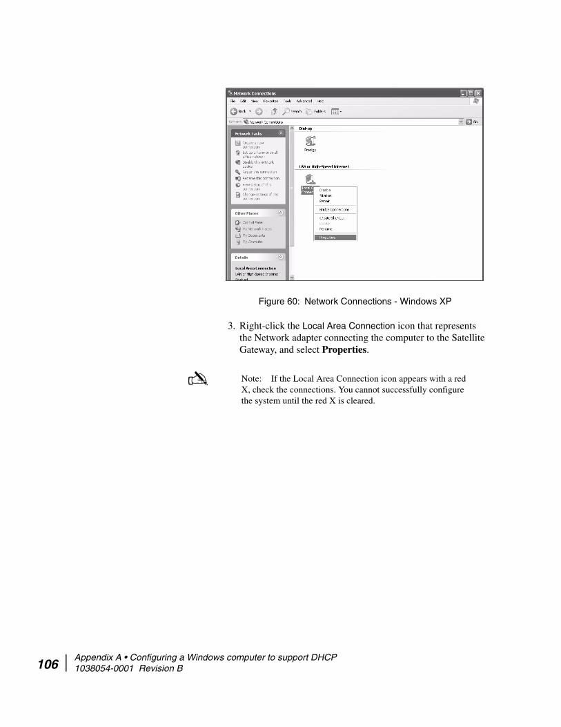
106
3. Right-click the Local Area Connection icon that represents the Network adapter connecting the computer to the Satellite Gateway, and select Properties.
Figure 60: Network Connections - Windows XP
Note: If the Local Area Connection icon appears with a red X, check the connections. You cannot successfully configure the system until the red X is cleared.
Appendix A • Configuring a Windows computer to support DHCP 1038054-0001 Revision B

4. Ensure that the Client for Microsoft Networks and Internet Protocol (TCP/IP) are installed and checked as shown in Figure 61. If NetBEUI is installed, uninstall it.
5. Highlight Internet Protocol (TCP/IP). Be careful not to uncheck the check box.
6. Click Properties. The Internet Protocol Properties window appears as shown in Figure 62.
Figure 61: Local Area Connection Properties - Windows XP
Figure 62: Internet Protocol Properties - Windows XP
Appendix A • Configuring a Windows computer to support DHCP 1038054-0001 Revision B 107
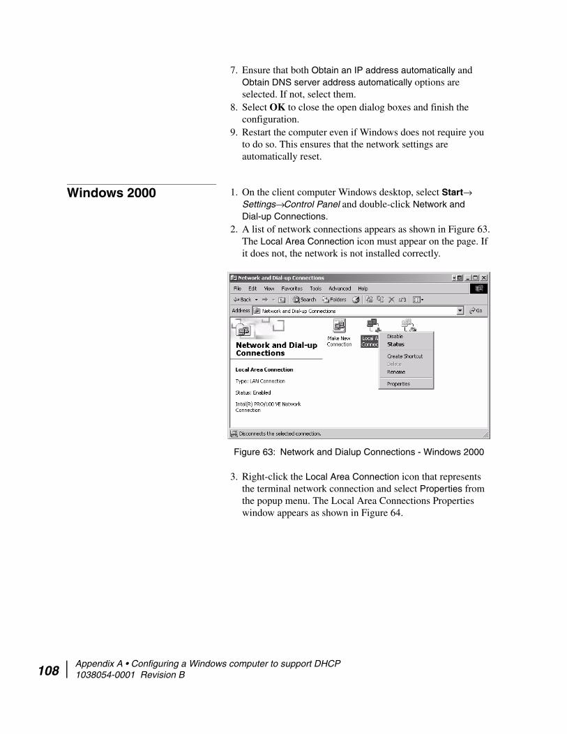
108
7. Ensure that both Obtain an IP address automatically and Obtain DNS server address automatically options are selected. If not, select them.
8. Select OK to close the open dialog boxes and finish the configuration.
9. Restart the computer even if Windows does not require you to do so. This ensures that the network settings are automatically reset.
Windows 2000 1. On the client computer Windows desktop, select Start→ Settings→ Control Panel and double-click Network and Dial-up Connections.
2. A list of network connections appears as shown in Figure 63. The Local Area Connection icon must appear on the page. If it does not, the network is not installed correctly.
3. Right-click the Local Area Connection icon that represents the terminal network connection and select Properties from the popup menu. The Local Area Connections Properties window appears as shown in Figure 64.
Figure 63: Network and Dialup Connections - Windows 2000
Appendix A • Configuring a Windows computer to support DHCP 1038054-0001 Revision B

4. Ensure that the Client for Microsoft Networks and Internet Protocol (TCP/IP) are installed and checked. If NetBEUI is installed, uninstall it.
5. Select Internet Protocol (TCP/IP). Be careful not to uncheck the check box.
Figure 64: Local Area Connection Properties - Windows 2000
Appendix A • Configuring a Windows computer to support DHCP 1038054-0001 Revision B 109

110
6. Click Properties. The Internet Protocol Properties window appears as shown in Figure 65.
7. Ensure that both Obtain an IP Address Automatically and Obtain DNS Server Address Automatically are selected. If not, select them.
8. Select OK to close the open dialog boxes and finish the configuration.
9. Restart the computer even if Windows does not require you to do so. This ensures that the network settings are automatically reset.
Figure 65: Internet Protocol Properties - Windows 2000
Appendix A • Configuring a Windows computer to support DHCP 1038054-0001 Revision B
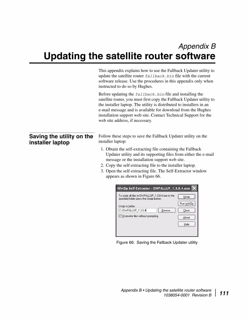
Appendix B
Updating the satellite router softwareThis appendix explains how to use the Fallback Updater utility to update the satellite router fallback.bin file with the current software release. Use the procedures in this appendix only when instructed to do so by Hughes.
Before updating the fallback.bin file and installing the satellite router, you must first copy the Fallback Updater utility to the installer laptop. The utility is distributed to installers in an e-mail message and is available for download from the Hughes installation support web site. Contact Technical Support for the web site address, if necessary.
Saving the utility on the installer laptop
Follow these steps to save the Fallback Updater utility on the installer laptop:
1. Obtain the self-extracting file containing the Fallback Updater utility and its supporting files from either the e-mail message or the installation support web site.
2. Copy the self-extracting file to the installer laptop.3. Open the self-extracting file. The Self-Extractor window
appears as shown in Figure 66.
Figure 66: Saving the Fallback Updater utility
Appendix B • Updating the satellite router software 1038054-0001 Revision B 111

112
4. Use the Browse button to select a location in which to unzip and save the utility and its supporting files.
5. Click Unzip.
Configuring the TCP/IP properties on the installer laptop
Before using the Fallback Updater utility, you must first manually configure the TCP/IP properties on the installer laptop. This section explains how to configure TCP/IP properties for Windows 98 Second Edition (SE), Windows Millennium Edition (Me), Windows 2000, and Windows XP operating systems.
Windows XP 1. From the Windows desktop on the installer laptop, select Start→ Settings→ Control Panel. Double-click the Network and Dial-up Connections icon.
2. A list of network adapters appears as shown in Figure 67. The Local Area Connection icon must appear under the LAN or High-Speed Internet heading. If it does not, the network is not installed correctly.
Note: Make a note of the location in which the utility and its supporting files are saved. You will need to know the location of these files to use the utility.
Note: If the Control Panel is in Category view, select Network and Internet Connections, then select Network Connections.
Appendix B • Updating the satellite router software 1038054-0001 Revision B

3. Right-click the Local Area Connection icon that represents the Network adapter connecting the computer to the Satellite satellite router, and click Properties.
4. Ensure that the Client for Microsoft Networks and Internet Protocol (TCP/IP) are installed and checked as shown in Figure 68. If NetBEUI is installed, uninstall it.
Figure 67: Network Connections - Windows XP
Note: If the Local Area Connection icon appears with a red X, check the connections. You cannot successfully configure TCP/IP properties until the red X is cleared.
Appendix B • Updating the satellite router software 1038054-0001 Revision B 113

114
5. Select Internet Protocol (TCP/IP). Be careful not to uncheck the check box.
6. Click Properties. The Internet Protocol Properties window appears as shown in Figure 69.
Figure 68: Local Area Connection Properties - Windows XP
Figure 69: Internet Protocol Properties - Windows XP
Appendix B • Updating the satellite router software 1038054-0001 Revision B

7. Select Use the following IP address.8. Type 192.168.0.2 in the IP address field.9. Type 255.255.255.252 in the Subnet mask field.
10. Click OK.
Windows 2000 1. On the installer laptop, select Start→ Settings→ Control Panel and double-click Network and Dial-up Connections.
2. A list of network adapters appears as shown in Figure 70.The Local Area Connection icon must appear on the page. If it does not, the network is not installed correctly.
3. Right-click the Local Area Connection icon that represents the network adapter connecting the computer to the satellite router, and select Properties. The Local Area Connections Properties window appears as shown in Figure 71.
Note: You do not need to enter information in the Default gateway, Preferred DNS server, or Alternate DNS server fields.
Figure 70: Network and Dial-up Connections - Windows 2000
Appendix B • Updating the satellite router software 1038054-0001 Revision B 115

116
4. Ensure that the Client for Microsoft Networks and Internet Protocol (TCP/IP) are installed and checked. If NetBEUI is installed, uninstall it.
5. Select Internet Protocol (TCP/IP). Be careful not to uncheck the checkbox.
6. Click Properties. The Internet Protocol Properties window appears as shown in Figure 72.
Figure 71: Local Area Connection Properties - Windows 2000
Figure 72: Internet Protocol Properties - Windows 2000
Appendix B • Updating the satellite router software 1038054-0001 Revision B

7. Select Use the following IP address.8. Type 192.168.0.2 in the IP address field.9. Type 255.255.255.252 in the Subnet mask field.
10. Click OK.11. Restart the computer even if Windows does not require you to
do so. This ensures that the network settings are automatically reset.
Updating the fallback.bin file
Follow the steps below to update the fallback.bin file. During this process, the files containing the current software release are transferred to the satellite router, overwriting the older files.
1. Confirm that the installer laptop Ethernet cable is connected to the HX200 satellite router by performing a ping test:a. Open a DOS command line prompt or Command window
on the installer laptop.b. Type ping 192.168.0.1.c. Press ENTER.
Continue with step 2 if the ping test is successful. Refer to Troubleshooting the update on page 119 if the ping test fails.
2. Navigate to the location on the laptop where you saved the Fallback Updater utility and its supporting files in Step 4 of Saving the utility on the installer laptop on page 111.
3. Launch the Fallback Updater utility by opening the HX_Updater.exe file.
4. Type 192.168.0.1 in the IP address field on the System Updater window as shown in Figure 73. This value is the HX200 IP address.
5. Click OK.
During the update process, status messages will appear in the message window between the address field and the OK button.
Note: You do not need to enter information in the Default gateway, Preferred DNS server, or Alternate DNS server fields.
Figure 73: Entering the satellite router IP address
Appendix B • Updating the satellite router software 1038054-0001 Revision B 117

118
When the update is complete, the utility automatically closes and the HX200 reboots.
Refer to Troubleshooting the update if the utility does not automatically close or the HX200 fails to reboot.
Appendix B • Updating the satellite router software 1038054-0001 Revision B

Troubleshooting the update
Perform these troubleshooting procedures if you are unable to update the fallback.bin file using the Fallback Updater utility:
1. Observe the message in the System Updater window message field on the system.Continue with step 2 if one of the following messages appears in the message window:Waiting for remote to come up...Unable to get login prompt
2. Test LAN connectivity between the installer laptop and satellite router by performing a ping test:a. Open a DOS command line prompt or Command window
on the installer laptop.b. Type ping 192.168.0.1.c. Press ENTER.Continue with Step 3 if the ping test fails. Verify that the Ethernet cable is securely attached to the installer laptop and the satellite router.
3. Verify that the installer laptop has an IP address of 192.168.0.2.If the address is incorrect or blank, refer to Configuring the TCP/IP properties on the installer laptop on page 112 for instructions on how to assign an IP address.
1. After verifying that the installer laptop is connected to the satellite router and its TCP/IP properties are properly configured, power cycle the satellite router by turning it off using the power switch on the rear panel, waiting 10 seconds, and then turning it back on.
2. Restart the utility and repeat the instructions in Updating the fallback.bin file on page 117.
3. Contact Technical Support if you are unable to update the fallback.bin file on the satellite router after completing steps 1 through 2.
Appendix B • Updating the satellite router software 1038054-0001 Revision B 119

120
Appendix B • Updating the satellite router software 1038054-0001 Revision B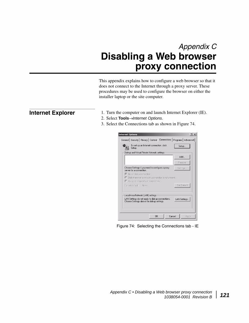
Appendix C
Disabling a Web browser proxy connection
This appendix explains how to configure a web browser so that it does not connect to the Internet through a proxy server. These procedures may be used to configure the browser on either the installer laptop or the site computer.
Internet Explorer 1. Turn the computer on and launch Internet Explorer (IE).2. Select Tools→ Internet Options.3. Select the Connections tab as shown in Figure 74.
Figure 74: Selecting the Connections tab - IE
Appendix C • Disabling a Web browser proxy connection 1038054-0001 Revision B 121

122
4. Deselect the Use a proxy server for the LAN check box as shown in Figure 75.
5. Click OK.
6. Close Internet Explorer and relaunch it to enable the changes.
Firefox 1. Turn the computer on and launch Firefox.2. Select Tools → Options.3. Click the Advanced button4. Select the Network tab as shown in Figure 76.
Figure 75: Accessing LAN settings - IE
Figure 76: Options Window - Firefox
Appendix C • Disabling a Web browser proxy connection 1038054-0001 Revision B

5. Click the Settings button; the Connection Settings window appears as shown in Figure 77.
6. Select the No Proxy option and click OK.7. Click OK.
Figure 77: Connection Settings - Firefox
Appendix C • Disabling a Web browser proxy connection 1038054-0001 Revision B 123

124
Appendix C • Disabling a Web browser proxy connection 1038054-0001 Revision B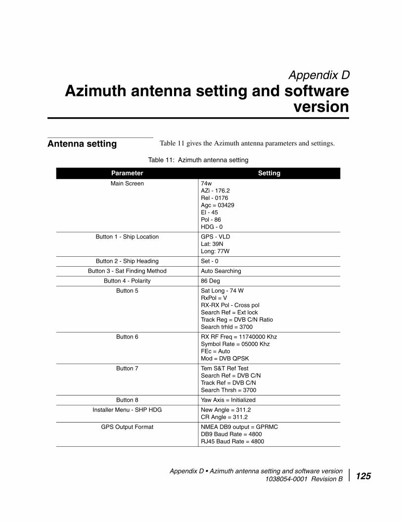
Appendix D
Azimuth antenna setting and software version
Antenna setting Table 11 gives the Azimuth antenna parameters and settings.
Table 11: Azimuth antenna setting
Parameter Setting
Main Screen 74wAZi - 176.2Rel - 0176Agc = 03429El - 45Pol - 86HDG - 0
Button 1 - Ship Location GPS - VLDLat: 39NLong: 77W
Button 2 - Ship Heading Set - 0
Button 3 - Sat Finding Method Auto Searching
Button 4 - Polarity 86 Deg
Button 5 Sat Long - 74 WRxPol = VRX-RX Pol - Cross polSearch Ref = Ext lockTrack Reg = DVB C/N RatioSearch trhld = 3700
Button 6 RX RF Freq = 11740000 KhzSymbol Rate = 05000 KhzFEc = AutoMod = DVB QPSK
Button 7 Tem S&T Ref TestSearch Ref = DVB C/NTrack Ref = DVB C/NSearch Thrsh = 3700
Button 8 Yaw Axis = Initialized
Installer Menu - SHP HDG New Angle = 311.2CR Angle = 311.2
GPS Output Format NMEA DB9 output = GPRMCDB9 Baud Rate = 4800RJ45 Baud Rate = 4800
Appendix D • Azimuth antenna setting and software version 1038054-0001 Revision B 125
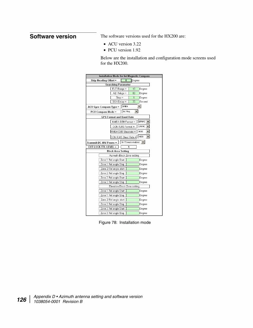
126
Software version The software versions used for the HX200 are:
• ACU version 3.22• PCU version 1.92
Below are the installation and configuration mode screens used for the HX200.
Figure 78: Installation mode
Appendix D • Azimuth antenna setting and software version 1038054-0001 Revision B

Figure 79: Configuration mode
Figure 80: Configuration mode #2
Appendix D • Azimuth antenna setting and software version 1038054-0001 Revision B 127

128
Appendix D • Azimuth antenna setting and software version 1038054-0001 Revision B
Appendix E
Seatel antenna settings and software version
Table 12: Seatel parameters and settings
Parameter Setting
Main Screens - 1 Lat 39 NLong 77 WHDG 0000
Main Screens - 2 AZ 175EL 045.6REL 322AGC 1602
Main Screen - 3 Sat 74 WTHRS 1488FREQ 1440NID ABCD
Appendix E • Seatel antenna settings and software version 1038054-0001 Revision B 129

130
Software version The software versions for the Seatel antenna are:
• PCU version 2.86• ACU version 6.04J
Figure 81 on page 131 illustrates the Seatel TMS.
Setup Screens EL Trim - 28Auto Thrs - 0000Az trim - 1465El Step Size - 0000Az step size - 000Setup Intg - 0000Search limit - 0000Searh delay - 0015Sweep Int - 0000System Type - 215Gyro type - 0002Polang type - 0072Pol offset - 0040Pol search - 6090Az limit 1 - 0000Az limit 2 - 0000El limit 3 - 0000Az limit 3 - 0000Az limit 4 - 0000El limit 3 - 0000Az limit 3 - 0000Az limit 4 - 0000El limit 34 - 0900Az limit 5 - 0000Az limit 6 - 0000El limit 56 - 00005v offset - 00005v search - 0000Tx Pol - 0002Trck Disp - 0000
Table 12: Seatel parameters and settings (Continued)
Parameter Setting
Appendix E • Seatel antenna settings and software version 1038054-0001 Revision B
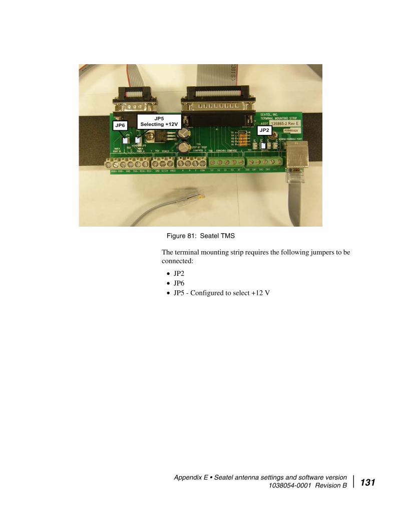
The terminal mounting strip requires the following jumpers to be connected:
• JP2• JP6• JP5 - Configured to select +12 V
Figure 81: Seatel TMS
Appendix E • Seatel antenna settings and software version 1038054-0001 Revision B 131

132
Appendix E • Seatel antenna settings and software version 1038054-0001 Revision B
Appendix F
Troubleshooting NMEA and TX mute/RX lock cable issues
In the event of any issues in NMEA information being sent between ACU and HX200 the following troubleshooting steps can be taken:
• Verify proper cable connectivity between HX200 and ACU.• Verify in the HX200’s Web interface that Total Rx and GLL
Info or RMC Info msg Processed increases over a period of 5 minutes. Refer to Figure 82.
Figure 82: Advanced screen
Appendix F • Troubleshooting NMEA and TX mute/RX lock cable issues 1038054-0001 Revision B 133

134
• For an Azimuth ACU, if these statistics are not increasing, connect a null modem cable between laptop serial port and the NMEA interface (DB-9 RS-232) on the ACU. Launch the PCs HyperTerminal and verify that ACU is sending NMEA sentences via the port.
• For Seatel ACU, if these statistics are not increasing, connect a cable between laptop and the RJ-45 modem console port. Launch the PCs HyperTerminal and verify that ACU is sending NMEA sentences via the port.
If the problem continues to persist contact your Hughes support personnel for further assistance.
Appendix F • Troubleshooting NMEA and TX mute/RX lock cable issues 1038054-0001 Revision B

Appendix G
LNB selection referenceThis appendix applies to the commissioning task of entering the radio parameters. As part of this task you select the LNB for your installation from a drop-down list.
If you are not sure which LNB to select on the Receive LNB Selection screen, the following illustrations may help you identify the installed LNB and which option you should select. The list of options you see depends on how the modem is configured. Refer to Figure 83 on page 136 for more information.
Appendix G • LNB selection reference 1038054-0001 Revision B 135

136
Figure 83: Select aid for Ku-band LNBs
Appendix G • LNB selection reference 1038054-0001 Revision B

Appendix G • LNB selection reference 1038054-0001 Revision B 137

138
Appendix G • LNB selection reference 1038054-0001 Revision B
Appendix H
Conforming with standards and directives
TIA IPoS standard The HX200 and HX260 satellite routers are compliant with the IP over Satellite Standard (IPoS) ratified by the Telecommunications Industry Association (TIA-1008A), first published in October 2003 and issued as Revision A in May 2006.
Certifications and cautions
Figure 84: IPoS symbol
CAUTIONAny changes or modifications to this equipment not expressly approved by the manufacturer could void the manufacturer’s warranty.
DANGERRisk of explosion if the battery is replaced by an incorrect type. Dispose of used batteries according to the instructions.
Appendix H • Conforming with standards and directives 1038054-0001 Revision B 139

140
Safety-operating conditions for Canada
In addition to the warnings and safety guidelines listed in this document, the following operating conditions apply to the HX200 and HX260 satellite routers used in Canada:
The Canadian Department of Communications label identifies certified equipment. This certification means that the equipment meets certain telecommunications network protective operational and safety requirements. The Department does not guarantee that the equipment will operate to the user's satisfaction.
Before installing the equipment, users should make sure they are permitted connect to the facilities of the local telecommunications company. The equipment must also be installed using an acceptable method of connection. In some cases, the company's inside wiring associated with a single line individual service may be extended by means of a certified connector assembly (telephone extension cord). The customer should be aware that compliance with the above conditions may not prevent degradation of service in some situations.
Repairs in Canada Repairs to certified equipment should be made by an authorized Canadian maintenance facility designated by the supplier. Any repairs or alterations made by the user to this equipment, or equipment malfunctions, may give the telecommunications company cause to request the user to disconnect the equipment.
Users should ensure for their own protection that the electrical ground connections of the power utility, telephone lines, and internal metallic water pipe system, if present, are connected together. This precaution may be particularly important in rural areas.
Safety, emission, and immunity standards
Table 13 identifies the system compliance with safety, emission, and immunity standards. The HX200 and HX260 comply with the European R&TTE (Radio and Telecommunications Terminal Equipment) directive as well as the EMI standards of the US (FCC) and Canada (CSA), as detailed in subsequent sections. The installation and maintenance procedures in the installation and configuration guides must be followed to ensure compliance with these standards.
CAUTIONDo not attempt to make such connections, instead contact the appropriate electrical inspection authority or electrician as appropriate.
Appendix H • Conforming with standards and directives 1038054-0001 Revision B

Canada Class B warning This Class B digital apparatus complies with Canadian ICES-003.
Cet appareil numérique de la classe B est conforme á la norme NMB-003 du Canada.
FCC part 15 notice This equipment has been tested and found to comply with the limits for a Class B digital device, pursuant to Part 15 of the FCC rules. These limits are designed to provide reasonable protection against harmful interference when the equipment is operated in a residential installation. This equipment generates, uses, and can radiate radio frequency energy and if not installed and used in accordance with the instruction manual may cause harmful interference to radio communications. However, there is no guarantee that interference will not occur in a particular installation. If this equipment does cause harmful interference to radio or television reception, which can be determined by turning the equipment off and on, the user is encouraged to try to correct the interference by one or more of the following measures:
• Reorient or relocate the receiving antenna.• Increase the separation distance between the equipment and
the receiver.• Connect the equipment int0 an outlet on a circuit different
from that to which the receiver is connected.
Table 13: System safety, emission, and immunity standards compliance
Type of standard
United States and Canada
Safety UL60950-1 for the United States
CAN/CSA-C22.2 No. 60950-1 for Canada(See additional information below.)
EN60950-1 for the European Union
Emissions FCC Part 15 for the United States(See additional information below.)
ICES-003 for Canada
EN55022 and EN301-489-12 for Europe
Immunity EN55024 and EN301-489-12 for Europe
Appendix H • Conforming with standards and directives 1038054-0001 Revision B 141

142
Consult the dealer or an experienced radio TV technician for help.
R&TTE notice This product is within the scope of the EU Radio Equipment and Telecommunications Terminal Equipment (R&TTE) Directive.
Material compliance
RoHS compliance Products supplied to this specification shall conform to Restriction of Hazardous Substances (RoHS).
The Directive 2002/95/EC of the European Parliament and of the Council of the 27th January 2003, on the restriction of the use of certain hazardous substances in electrical and electronic equipment, requires the reduction of the substances Lead, Mercury, Cadmium, Hexavalent Chromium, Polybrominated Biphenyls (PBB), and Polybrominated Diphenyl Ethers (PBDE) in electronic products by July 1, 2006. Unless otherwise noted, all materials used must be compliant with this directive and any subsequent revisions or amendments except Lead.
The maximum acceptable RoHS concentrations are listed in Table 14:
RoHs compliance with exemptions
Please note the following exemption of the Directive 2002/95/EC:
Lead in solders for servers, storage and storage array systems, network infrastructure equipment for switching, signaling, transmission as well as network management for
CAUTIONThis is a class B product. In a domestic environment this product may cause radio interference in which case the user may be required to take adequate measures.
Table 14: Maximum acceptable RoHS concentration
Substance Concentration
Cadmium 0.01% wt (max. concentration by weight in homogenous materials)
Lead 0.1% wt (max. concentration by weight in homogenous materials) Exempted
Mercury: 0.1% wt (max. concentration by weight in homogenous materials)
Hexavalent chromium 0.1% wt (max. concentration by weight in homogenous materials)
PBB 0.1% wt (max. concentration by weight in homogenous materials)
PBDE 0.1% wt (max. concentration by weight in homogenous materials)
Appendix H • Conforming with standards and directives 1038054-0001 Revision B

telecommunications (with a specific time limit for this exemption).
Appendix H • Conforming with standards and directives 1038054-0001 Revision B 143

144
Appendix H • Conforming with standards and directives 1038054-0001 Revision B
Acronyms and abbreviations
A
AC – Alternating current
ACM – Adaptive coding and modulation
ACP – Automatic cross-polarization
B
BCH – Bose Chahaudary Hocquenghum (algorithm)
C
C – Celsius
CCM – Constant coding modulation
D
dBm –
DNCC – Dynamic network control cluster
DNS – Domain name service
DVB – Digital video broadcast
DVB-S2 – Digital video broadcast - second generation
F
FEC – Forward error correction
ft – Foot
G
GPS – Global positioning system
H
HTTP – Hypertext transfer protocol
I
ICMP – Internet control message protocol
IDU – Indoor unit
IE – Internet Explorer
IFL – Interfacility link
IPoS – IP over satellite
L
lb – Pound
M
Max – Maximum
Min – Minimum
Msps – Megasymbol(s) per second
N
NAP – Network Access Provider
NAPT – Network address port translation
NAT – Network address translation
NIC – network interface card
O
ODU – Outdoor unit
OS – Operating system
P
PAT – Port address translation
PBB – Polybrominated biphenyls
PBDE – Polybrominated diphenyl ethers
PSK – Phase-shift keying
• Acronyms and abbreviations 1038054-0001 Revision B 145
146
Q
QoS – Quality of service
QPSK – Quadriphase shift keying
R
R&TTE – Radio Equipment and Telecommunications Terminal Equipment
RoHS – Restriction of Hazardous Substances
Rx – Receive
S
Sec – Seconds
T
TCP – Transmission control protocol
TIA – Telecommunications Industry Association
Tx – Transmit
U
UDP – User datagram protocol
URL – Uniform resource locator
W
WINS – Windows internet naming service
• Acronyms and abbreviations 1038054-0001 Revision B

Index
A
ACS 39Advanced pages 89Antenna
pointing 34Antenna Location screen 41Antenna, pointing 36, 49Auto
selection 8Auto-commissioning
server 39Azimuth antenna 125
setting and software 125Azimuth KNS-150 2
B
Blockupconverter 5
Broadband Satellite Setup screen 41
C
Cablescoaxial 13connecting 14connecting to HX150 14
Coastal Maritime Service 2Coaxial
cablesinstalling 13
Commissioningantenna pointing 34auto 8HX200 41HX200 satellite router 7manual 8methods 21
manual 21satellite-based (SBC) 37
configuration file 39IP address 37
Completing
HX200 installation 55Configuring
DHCP 105installation PC 105TCP/IP 112Windows 2000 108
Confirmingfiles 55
Connectingcables 13, 14Ethernet cables 14power cables 14to a computer 56
Connectivitytest 64, 78, 100
Contactinginformation 8Tech Support 64
CreatingSystem Control Center shortcut 58
D
Datainterfaces 4
DHCP 7, 105DVB-S2
compliant outroute 4Dynamic Host Configuration Protocol see DHCP
E
Enterprisenetwork
connectivity 101Equipment
specifications 5Ethernet 12
cables 14
F
Fallbackbin file
updating 111, 117
• Index 1038054-0001 Revision B 147
148
updater utility 111configuring TCP/IP 112saving 111saving on installer laptop 111updating fallback.bin file 111
Fallback Updater utilitytroubleshooting 119updating fallback.bin file 117
Firefox 122Firefox, disabling proxy server connection 122Firewall 101, 103
configuration 78creating firewall rules 80deleting firewall rules 82enabling and disabling the firewall 83firewall rule fields 81modifying firewall rules 82rule restrictions 80
statistics 83resetting 84
H
HXsystem gateway, testing connection to 64
HX200commissioning 7, 41connectivity
problems 96description 1equipment specifications 5installing 7LEDs 18, 91
normal operation 92specifications 5
I
InstallationPC
configuring for installation 7Installing
items required 11satellite router 7site requirements 13
Interfacessignal and data 4
Internet Explorer, disabling proxy server connection 121IP 37
L
LAN 92LEDs 91
appearance 92HX200 18
Linearradio 13
M
Manualcommissioning 21
NOC override 34parameters 22
Materialcompliance 142
RoHs 142with exemptions 142
Mobilityradial speed 4
N
NOCoverride 34
O
ODUtransmission 3
OPI 34Optional features 78
firewall 78port forwarding 78
Outdoorunit 5
OutrouteDVB-S2 compliant 4
P
Pingtest
description 100
• Index 1038054-0001 Revision B

Portforwarding
configuration 85Port forwarding
configurationcreating rules 86deleting rules 87modifying rules 87restrictions 86
Powercables 14
Powering upLEDs 18
Preparingto install 11
PrintingSystem Information page 57
Proxy server, disabling 121
R
Rack mount, optional kit 2Receive Radio Parameters 31Receiver
specifications 6Reception Information page 66Requirements
laptop 12site 12
S
SafetyCanada Class B warning 141certifications and cautions 139
Canadian operating conditions 140emission and immunity standards 140FCC part 15 notice 141
Satellite routercommissioning 7installing 7specifications 5
Saturatedtransmit 3
Savingfallback updater utility 111
SBCcommissioning 37
configuration file 12uploading 39
Seatel antenna 129settings and software version 129
Seatel DAC 220 2Setup screen 41Shortcut
creating 58Signal
interfaces 4Site
requirementsmemory 12network interface 12operating systems 12processor 12
Specificationsgeneral 5receiver 6satellite router 5
Standardssafety, emission, and immunity 140
Statusmessages
receive 67transmit 70
Systemindicators
Reception Info 63System Info 63System Status 62Transmission Info 63
System Control Centeraccessing 61Home page 61, 62
links on 63system indicators on 62
Reception Info page 66System Info page 76System Status page 65Transmission Info page 70
System Information page 76printing 57
System Status page 65
• Index 1038054-0001 Revision B 149

150
T
TCP acceleration, checking 99Transmission
types 3Transmission Information page 70Transmit
cables 13code
messages 70Transmitter
specifications 6Troubleshooting
access to enterprise resources 56accessing
network resources 97System Control Center 96, 98
commissioning 98connectivity 96
network connectivity 101system gateway 100
DNS settings 102fallback.bin file update 119hot cable connector 103intermittent operation 104no browsing 103receive signal 98signal strength 98slow transmission 104TCP acceleration 99transmit signal 98viruses 103Web acceleration 99
U
Updatingfallbck.bin file 117
V
Viewinghelp topics 64
Viruses 103
W
Web browser, disabling proxy server connection 121Windows
2000 108, 115XP 105, 112
• Index 1038054-0001 Revision B