hybrid control strategy for five-fingered smart prosthetic
TRANSCRIPT

Hybrid Control Strategy for Five-Fingered Smart Prosthetic Hand
Cheng-Hung Chen, Student Member, IEEE, D. Subbaram Naidu, Fellow, IEEE, Alba Perez-Gracia, and
Marco P. Schoen, Member, IEEE
Abstract—This paper presents a hybrid of soft computingor control technique of adaptive neuro-fuzzy inference system(ANFIS) and hard computing or control technique of finite-timelinear quadratic optimal control for the 14 degrees of freedom(DOFs), five-fingered smart prosthetic hand. In particular,ANFIS is used for inverse kinematics, and the optimal controlis used for feedback linearized dynamics to minimize trackingerror. The simulations of this hybrid controller, when com-pared with the proportional-integral-derivative (PID) controllershowed enhanced performance.
Index Terms—Prosthetic Hand, Optimal Control, PID Con-trol, Adaptive Neuro-Fuzzy Inference System, Hybrid Control
I. INTRODUCTION
Over the last several yeas, attempts have been made to
build a prosthetic hand to replace human hand that fully sim-
ulate the various natural/human-like operations of moving,
grasping, lifting, twisting and so on. Replicating the human
hand in all its various functions is still a challenging task
due to the extreme complexity of human hand, which has
27 bones, controlled by about 38 muscles to provide the
hand with 22 degrees of freedom (DOFs), and incorporates
about 17,000 tactile units of 4 different units [1]. Artificial
hands have been around for the last several years developed
by various researchers in the field [1]–[4]. However, about
35% of the amputees [5] do not use their prosthetic hand
regularly due to various reasons such as poor functionality
of the presently available prosthetic hands and psychological
problems. To overcome these problems, one has to design
and develop an artificial hand which “mimics the human
hand as closely as possible,” both in functionality and
appearance.
Soft computing/control (SC) or computational intelligence
(CI) [6] is an emerging field based on synergy and seamless
integration of neural networks (NN), fuzzy logic (FL) and
genetic algorithms (GA) [7]. Arslan et al. [8] developed the
biomechanical model with a tendon configuration of the 3
Cheng-Hung Chen is with the Measurement and Control EngineeringResearch Center and the Department of Biological Sciences, Idaho StateUniversity, ID 83209, USA (email: [email protected]).
D. Subbaram Naidu is with the Measurement and Control EngineeringResearch Center and the Department of Electrical Engineering, Idaho StateUniversity, ID 83209, USA (email: [email protected]).
Alba Perez-Gracia is with the Measurement and Control EngineeringResearch Center and the Department of Mechanical Engineering, Idaho State
University, ID 83209, USA on leave with Institut de Robotica i InformaticaIndustrial (UPC-CSIC) c/ Llorens i Artigas 4-6, Barcelona, Spain (email:[email protected]).
Marco P. Schoen is with the Measurement and Control EngineeringResearch Center and the Department of Mechanical Engineering, Idaho StateUniversity, ID 83209, USA (email: [email protected]).
DOFs index finger of the human hand and the fuzzy sliding
mode controller in which a fuzzy logic unit tuned the slope
of the sliding surface was introduced to generate the required
tendon forces during closing and opening motion. Onozato
and Maeda [9] utilized two neural networks learning inverse
kinematic and inverse dynamic to control the positions of
2 DOFs SCARA robot. Aggarwal et al. [10] obtained the
neural recordings from rhesus monkeys with three different
movements, the flexion/extension of each finger, the rotation
of wrist and dexterous grasps and designed separate decoding
filters for each movement by using multilayer feedforward
artificial neural network (ANN) in order to be implemented
in real-time MATLAB/Simulink. An online decentralized
neural network control design without deriving the dynamic
model for a class of large-scale uncertain robot manipulator
systems was proposed by Tan et al. [11]. Kato et al. [12]
expressed the reaction of brains to the adaptable prosthetic
system for a 13 DOFs EMG signal controlled prosthetic hand
with an EMG pattern recognition learning by artificial neural
networks. In addition, functional magnetic resonance imag-
ing (f-MRI) was used to analyze the reciprocal adaptation
between the human brain and the prosthetic hand by the
plasticity of the motor and sensory cortex area in brains
based on the variations in the phantom upper limb. Marcos
et al. [13] proposed the closed-loop pseudo-inverse method
with genetic algorithms (CLGA) to minimize the largest
joint displacement between two adjacent configurations, the
total level of joint velocities, the joint accelerations, the total
joint torque, and the total joint power consumption for the
trajectory planning of 3 DOFs redundant robots. Kamikawa
and Maeno [14] used genetic algorithm to optimize locations
of pivots and grasping force and designed one ultrasonic
motor to move 15 compliant joints for an underactuated five-
finger prosthetic hand.
Hard computing/control (HC) techniques comprise pro-
portional integral derivative (PID) control [15]–[18], optimal
control [19], [20] and so on with specific applications to
prosthetics. SC can be used at upper levels of the overall
mission where human involvement and decision making is
of primary importance. HC can be used at lower levels
for accuracy, precision, stability and robustness. Therefore,
the integration of SC and HC methodologies could solve
problems that cannot be solved satisfactorily by using either
methodology alone and lead to high performance, robust,
autonomous and cost-effective systems.
Our previous works [17], [18] for a two-fingered (thumb
and index finger) smart prosthetic hand showed that PID con-
troller results in the overshooting and oscillation, which were
Joint 48th IEEE Conference on Decision and Control and28th Chinese Control ConferenceShanghai, P.R. China, December 16-18, 2009
ThBIn4.9
978-1-4244-3872-3/09/$25.00 ©2009 IEEE 5102

also demonstrated by Subudhi and Morris [15] and Liu et
al. [16]. To overcome the problem, fusion of soft computing
technique of adaptive neuro-fuzzy inference system (ANFIS)
and finite-time linear quadratic optimal control strategy for
14 DOFs prosthetic hand is precisely the main goal of this
work.
In this paper, we first consider briefly the trajectory
planning problem, human hand anatomy and the inverse
kinematics for two-link thumb and the remaining three-
link fingers (index, middle, ring, and little) using ANFIS.
Next, the dynamics of the hand is derived and feedback
linearization technique is used to obtain linear tracking
error dynamics. Then the finite-time linear quadratic optimal
controller is designed to minimize the tracking error. The
resulting overall hybrid system incorporating both soft and
hard control techniques is simulated with practical data for
the hand and found to be better than the previous works. The
last section provides conclusions and future work.
II. MODELING
A. Trajectory Planning and Inverse Kinematics
The trajectory planning using cubic polynomial was dis-
cussed in our previous work [17], [18], [21]–[23] for a two-
fingered (thumb and index finger) smart prosthetic hand. As
shown in Figure 1, index finger, middle finer, ring finer, and
Fig. 1. The Joints of Five-Finger Prosthetic Hand Reaching a Rectangular
Rod
little finger include three revolute joints in order to do the
angular movements. Metacarpal-phalangeal (MCP) joint is
located between metacarpal and proximal phalange bone;
proximal and distal interphalangeal (PIP and DIP) joints
separate the phalangeal bones. Thumb contains metacarpal-
phalangeal (MCP) and interphalangeal (IP) joints [24]. In
this work, qj1, q
j2
and qj3
represent the angular positions (or
joint angles) of the first joint MCP j, the second joint PIP j
and the third joint DIP j of index finger (j = i), middle
finger (j = m), ring finger (j = r) and little finger (j = l),
respectively; qt1
and qt2
are the angular positions of the first
joint MCP t and the second joint IP t of thumb (t).
A desired trajectory is usually specified in Cartesian
space and the trajectory controller is easily performed in
the joint space. Hence, it is necessary to convert Cartesian
trajectory planning to the joint space [25]–[27]. Using inverse
kinematics, the joint angles of each finger need to be obtained
from the known fingertip positions (joint space). Then the
angular velocities and angular accelerations of each finger
can be obtained from the velocities and accelerations of
fingertips by Jocobian. Figure 2 shows that XG , Y G, and
Fig. 2. The Definition of Global Coordinate and Local Coordinates
ZG are the three axes of the global coordinate. The local
coordinate xt-yt-zt of the thumb can be reached by rotating
through angles α and β to XG and Y G of the global
coordinate, subsequently. The local coordinate xi-yi-zi of
index finger can be obtained by rotating through angle α
to XG and then translating the vector di of the global
coordinate; similarly, the local coordinate xj-yj -zj of middle
finger (j = m), ring finger (j = r), and little finger (j = l)
can be obtained by rotating through angle α to XG and then
translating the vector dj (j = m, r and l) of the global
coordinate. The inverse kinematics of two-link thumb and
three-link fingers was discussed in our previous publications
[17], [18], [21]–[23] for a two-fingered (thumb and index
finger) smart prosthetic hand.
B. Dynamics of Hand
The dynamic equations of hand motion are derived via
Lagrangian approach using kinetic energy and potential
energy as [25]–[28]
d
dt
(
∂L
∂q
)
−∂L
∂q= τ , (1)
where L is Lagrangian; q and q represent the angular
velocity and angle vectors of joints, respectively; τ is the
given torque vector at joints. The Lagrangian L can be
expressed as
L = T − V, (2)
where T and V denote kinetic and potential energies, respec-
tively. Substituting (2) into (1) gives the relation as
M(q)q + C(q, q) + G(q) = τ , (3)
ThBIn4.9
5103

where M(q) is the inertia matrix; C(q, q) is the Corio-
lis/centripetal vector and G(q) is the gravity vector. (3) can
be also written as
M(q)q + N(q, q) = τ , (4)
where N(q, q) = C(q, q)+G(q) represents nonlinear terms.
The dynamic relations for the two-link thumb and the three-
link fingers are quite lengthy and omitted here due to lack
of space [8], [21], [29].
III. CONTROL TECHNIQUES
A. Feedback Linearization
The nonlinear dynamics represented by (4) is to be
converted into a linear state-variable system by finding a
transformation using feedback linearization technique [28],
[30]. Alternative state-space equations of the dynamics can
be obtained by defining the position/velocity state x(t) of
the joints as
x(t) = [q(t)′ q(t)′]′
. (5)
Let us repeat the dynamical model and rewrite (4) as
d
dtq(t) = −M(q(t))
−1[N(q(t), q(t)) − τ (t)] . (6)
Thus, from (5) and (6), we can derive a linear state-variable
equation in Brunovsky canonical form as
x(t) =
[
0 I
0 0
]
x(t) +
[
0
I
]
u(t) (7)
with its control input vector given by
u(t) = −M(q(t))−1
[N(q(t), q(t)) − τ (t)] . (8)
Let us suppose the prosthetic hand is required to track the
desired trajectory qd(t) described under path generation or
tracking. Then, the tracking error e(t) is defined as
e(t) = qd(t) − q(t). (9)
Here, qd(t) is the desired angle vector of joints and can be
obtained by trajectory planning [17], [18], [21]–[23]; q(t) is
the actual angle vector of joints. Differentiating (9) twice, to
get
e(t) = qd(t) − q(t), e(t) = qd(t) − q(t). (10)
Substituting (6) into (10) yields
e(t) = qd(t) + M(q(t))−1
[N(q(t), q(t)) − τ (t)] (11)
from which the control function can be defined as
u(t) = qd(t) + M(q(t))−1 [N(q(t), q(t)) − τ (t)] . (12)
This is often called the feedback linearization control law,
which can also be inverted to express it as
τ (t) = M(q(t)) [qd(t) − u(t)) + N(q(t), q(t)] . (13)
Using the relations (10) and (12), and defining state vector
x(t) = [e(t)′ e(t)′]′, the tracking error dynamics can be
written as
x(t) =
[
0 I
0 0
]
x(t) +
[
0
I
]
u(t). (14)
Note that this is in the form of a linear system such as
x(t) = Ax(t) + Bu(t). (15)
B. Hybrid PID Controller
Figure 3 shows the block diagram of a hybrid PID con-
troller for five-fingered prosthetic hand with control signal
as
u(t) = −KPe(t) −KI
∫
e(t)dt − KDe(t) (16)
with the proportional KP, integral gain matrix KI, and
derivative KD diagonal gain matrices. We then rewrite (13)
as
τ (t) = M(q(t))[qd(t) + KPe(t) + KI
∫
e(t)dt
+KD e(t)) + N(q(t), q(t)]. (17)
Fig. 3. Block Diagram of a Hybrid PID Controller for Prosthetic Hand
C. Hybrid Finite-Time Linear Quadratic Optimal Control
For the linear system (15), we can formulate the finite-time linear quadratic optimal control problem (as shown inFigure 4) by defining a performance index J [20] such as
J =1
2x′(tf )F(tf)x(tf )
+1
2
Z tf
t0
ˆ
x′(t)Q(t)x(t) + u′(t)R(t)u(t)˜
dt (18)
where the terminal cost matrix F(tf ) and the error
weighted matrix Q(t) are positive semidefinite matrices,
respectively; the control weighted matrix R(t) is a positive
definite matrix. The optimal control u∗(t) is given by
u∗(t) = −R−1(t)B′P(t)x∗(t) = −K(t)x∗(t). (19)
ThBIn4.9
5104
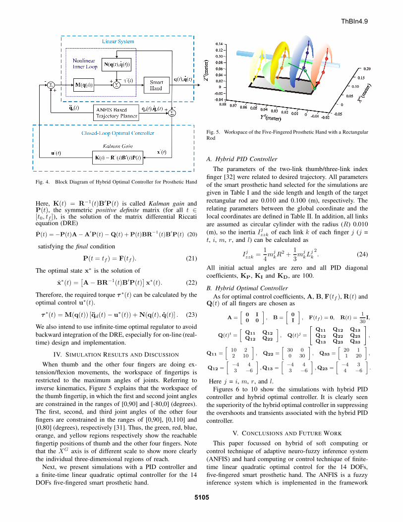
Fig. 4. Block Diagram of Hybrid Optimal Controller for Prosthetic Hand
Here, K(t) = R−1(t)B′P(t) is called Kalman gain andP(t), the symmetric positive definite matrix (for all t ∈
[t0, tf ]), is the solution of the matrix differential Riccatiequation (DRE)
P(t) = −P(t)A −A′
P(t) − Q(t) + P(t)BR−1(t)B′
P(t) (20)
satisfying the final condition
P(t = tf) = F(tf ). (21)
The optimal state x∗ is the solution of
x∗(t) =[
A− BR−1(t)B′P(t)]
x∗(t). (22)
Therefore, the required torque τ∗(t) can be calculated by the
optimal control u∗(t).
τ∗(t) = M(q(t)) [qd(t) − u∗(t)) + N(q(t), q(t)] . (23)
We also intend to use infinite-time optimal regulator to avoid
backward integration of the DRE, especially for on-line (real-
time) design and implementation.
IV. SIMULATION RESULTS AND DISCUSSION
When thumb and the other four fingers are doing ex-
tension/flexion movements, the workspace of fingertips is
restricted to the maximum angles of joints. Referring to
inverse kinematics, Figure 5 explains that the workspace of
the thumb fingertip, in which the first and second joint angles
are constrained in the ranges of [0,90] and [-80,0] (degrees).
The first, second, and third joint angles of the other four
fingers are constrained in the ranges of [0,90], [0,110] and
[0,80] (degrees), respectively [31]. Thus, the green, red, blue,
orange, and yellow regions respectively show the reachable
fingertip positions of thumb and the other four fingers. Note
that the XG axis is of different scale to show more clearly
the individual three-dimensional regions of reach.
Next, we present simulations with a PID controller and
a finite-time linear quadratic optimal controller for the 14
DOFs five-fingered smart prosthetic hand.
Fig. 5. Workspace of the Five-Fingered Prosthetic Hand with a Rectangular
Rod
A. Hybrid PID Controller
The parameters of the two-link thumb/three-link index
finger [32] were related to desired trajectory. All parameters
of the smart prosthetic hand selected for the simulations are
given in Table I and the side length and length of the target
rectangular rod are 0.010 and 0.100 (m), respectively. The
relating parameters between the global coordinate and the
local coordinates are defined in Table II. In addition, all links
are assumed as circular cylinder with the radius (R) 0.010
(m), so the inertia Ijzzk of each link k of each finger j (j =
t, i, m, r, and l) can be calculated as
Ij
zzk =1
4m
j
kR2 +1
3m
j
kLj
k
2
. (24)
All initial actual angles are zero and all PID diagonal
coefficients, KP, KI and KD, are 100.
B. Hybrid Optimal Controller
As for optimal control coefficients, A, B, F(tf ), R(t) andQ(t) of all fingers are chosen as
A =
»
0 I0 0
–
, B =
»
0I
–
, F(tf) = 0, R(t) =1
30I,
Q(t)t =
»
Q11 Q12
Q12 Q22
–
, Q(t)j =
2
4
Q11 Q12 Q13
Q12 Q22 Q23
Q13 Q23 Q33
3
5 ,
Q11 =
»
10 22 10
–
, Q22 =
»
30 00 30
–
, Q33 =
»
20 11 20
–
,
Q12 =
»
−4 43 −6
–
,Q13 =
»
−4 43 −6
–
, Q23 =
»
−4 34 −6
–
.
Here j = i, m, r, and l.
Figures 6 to 10 show the simulations with hybrid PID
controller and hybrid optimal controller. It is clearly seen
the superiority of the hybrid optimal controller in suppressing
the overshoots and transients associated with the hybrid PID
controller.
V. CONCLUSIONS AND FUTURE WORK
This paper focussed on hybrid of soft computing or
control technique of adaptive neuro-fuzzy inference system
(ANFIS) and hard computing or control technique of finite-
time linear quadratic optimal control for the 14 DOFs,
five-fingered smart prosthetic hand. The ANFIS is a fuzzy
inference system which is implemented in the framework
ThBIn4.9
5105

TABLE I
PARAMETER SELECTION OF THE SMART HAND
Parameters Values
Thumb
Time (t0 ,tf )∗ 0, 20 (sec)
Desired Initial Position (Xt0
,Y t0
)∗∗ 0.035, 0.060 (m)
Desired Final Position (Xtf
,Y tf
)∗∗ 0.0495, 0.060 (m)
Desired Initial Velocity (Xt0
,Y t0
)∗ 0, 0 (m/s)
Desired Final Velocity (Xtf
,Y tf
)∗ 0, 0 (m/s)
Length (Lt1
,Lt2
) 0.040, 0.040 (m)
Mass (mt1
,mt2
) 0.043, 0.031 (kg)
Index Finger
Desired Initial Position (Xi0
,Y i0
)∗∗ 0.065, 0.080 (m)
Desired Final Position (Xif ,Y i
f )∗∗ 0.010, 0.060 (m)
Length (Li1
,Li2
,Li3
) 0.040, 0.040, 0.030 (m)
Mass (mi1
,mi2
,mi3
) 0.045, 0.025, 0.017 (kg)
Middle FingerDesired Initial Position (Xm
0,Y m
0)∗∗ 0.065, 0.080 (m)
Desired Final Position (Xmf ,Y m
f )∗∗ 0.005, 0.060 (m)
Length (Lm1
,Lm2
,Lm3
) 0.044, 0.044, 0.033 (m)Mass (mm
1,mm
2,mm
3) 0.050, 0.028, 0.017 (kg)
Ring Finger
Desired Initial Position (Xr0
,Y r0
)∗∗ 0.065, 0.080 (m)Desired Final Position (Xr
f,Y r
f)∗∗ 0.010, 0.060 (m)
Length (Lr1
,Lr2
,Lr3
) 0.040, 0.040, 0.030 (m)Mass (mr
1,mr
2,mr
3) 0.041, 0.023, 0.014 (kg)
Little Finger
Desired Initial Position (Xl0
,Y l0
)∗∗ 0.055, 0.080 (m)
Desired Final Position (Xlf ,Y l
f )∗∗ 0.020, 0.060 (m)
Length (Ll1
,Ll2
,Ll3
) 0.036, 0.036, 0.027 (m)
Mass (ml1
,ml2
,ml3
) 0.041, 0.023, 0.014 (kg)∗All fingers use the same parameters.∗∗All parameters are in local coordinates.
TABLE II
PARAMETER SELECTION OF THE RELATION BETWEEN GLOBAL AND
LOCAL COORDINATES
Parameters Values
α 90 (degrees)β 45 (degrees)
di (0.035, 0, 0) (m)dm (0.040, 0, -0.020) (m)dr (0.035, 0, -0.040) (m)
dl (0.025, 0, -0.060) (m)
of adaptive networks which provides the best optimization
tool to find parameters that best fits the data. In particular,
ANFIS was used for inverse kinematics, and the optimal
control was used to minimize tracking error using feed-
back linearized dynamics . The simulations of this hybrid
controller, when compared with the proportional-integral-
derivative (PID) controller showed enhanced performance.
Work is underway to extend this methodology to 22 DOFs,
five-fingered, three-dimensional smart prosthetic hand.
ACKNOWLEDGMENTS
The financial support for this research from the
Telemedicine Advanced Technology Research Center
(TATRC) of the U.S. Department of Defense (DoD) is
gratefully acknowledged.
0 5 10 15 20−40
−20
0
20
40
60
80
100
Time (seconds)
Tra
ckin
g E
rrors
(deg
)
Joint 1 of Thumb (PID)
Joint 2 of Thumb (PID)
Joint 1 of Thumb (Optimal)
Joint 2 of Thumb (Optimal)
0 5 10 15 20−60
−40
−20
0
20
40
60
80
100
120
Time (seconds)
Join
t A
ngle
s (d
eg)
Desired Joint 1
Desired Joint 2
Actual Joint 1 (PID)
Actual Joint 2 (PID)
Actual Joint 1 (Optimal)
Actual Joint 2 (Optimal)
Fig. 6. Tracking Errors (left) and Joint Angles (right) for PID and OptimalControllers of Thumb
0 5 10 15 20−10
−5
0
5
10
15
20
25
30
35
Time (seconds)
Tra
ckin
g E
rrors
(deg
)
Joint 1 of Index Finger (PID)
Joint 2 of Index Finger (PID)
Joint 3 of Index Finger (PID)
Joint 1 of Index Finger (Optimal)
Joint 2 of Index Finger (Optimal)
Joint 3 of Index Finger (Optimal)
0 5 10 15 200
10
20
30
40
50
60
70
80
90
Time (seconds)
Join
t A
ngle
s (d
eg)
Desired Joint 1
Desired Joint 2
Desired Joint 3
Actual Joint 1 (PID)
Actual Joint 2 (PID)
Actual Joint 3 (PID)
Actual Joint 1 (Optimal)
Actual Joint 2 (Optimal)
Actual Joint 3 (Optimal)
Fig. 7. Tracking Errors (left) and Joint Angles (right) for PID and Optimal
Controllers of Index Finger
REFERENCES
[1] M. Zecca, S. Micera, M. Carrozza, and P. Dario, “Control of multifunc-
tional prosthetic hands by processing the electromyographic signal,”Critical ReviewsTM in Biomedical Engineering, vol. 30, pp. 459–485,2002, (Review article with 96 references).
[2] J. C. K. Lai, M. P. Schoen, A. Perez-Gracia, D. S. Naidu, and S. W.
Leung, “Prosthetic devices: Challenges and implications of roboticimplants and biological interfaces,” Proceedings of the Institute ofMechanical Engineers (IMechE), Part H: Journal of Engineering in
Medicine, vol. 221, no. 2, pp. 173–183, January 2007, special Issueon Micro and Nano Technologies in Medicine.
[3] L. Zollo, S. Roccella, E. Guglielmelli, M. C. Carrozza, and P. Dario,“Biomechatronic design and control of an anthropomorphic artificial
hand for prosthetic and robotic applications,” IEEE/ASME Transac-tions on Mechatronics, vol. 12, no. 4, pp. 418–429, August 2007.
[4] D. S. Naidu, C.-H. Chen, A. Perez, and M. P. Schoen, “Controlstrategies for smart prosthetic hand technology: An overview,” in
Proceedings of the 30th Annual International IEEE EMBS Conference,Vancouver, Canada, August 20-24 2008, pp. 4314–4317.
[5] D. J. Atkins, D. C. Y. Heard, and W. H. Donovan, “Epidemiologicoverview of individuals with upper limb loss and their reported
research priorities,” Journal of Prosthetic and Orthotics, vol. 8, no. 1,pp. 2–11, 1996.
[6] A. Konar, Computational Intelligence: Principles, Techniques andApplications. Berlin, Germany: Springer-Verlag, 2005.
[7] F. Karray and C. De Silva, Soft Computing and Intelligent SystemsDesign: Theory, Tools and Applications. Harlow, England, UK:
Pearson Educational Limited, 2004.[8] Y. Z. Arslan, Y. Hacioglu, and N. Yagiz, “Prosthetic hand finger control
using fuzzy sliding modes,” Journal of Intelligent and Robotic Systems,vol. 52, pp. 121–138, 2008.
[9] K. Onozato and Y. Maeda, “Learning of inverse-dynamics and inverse-kinematics for two-link scara robot using neural networks,” in The So-
ThBIn4.9
5106

0 5 10 15 20−20
−10
0
10
20
30
40
50
Time (seconds)
Tra
ckin
g E
rrors
(deg
)
Joint 1 of Middle Finger (PID)
Joint 2 of Middle Finger (PID)
Joint 3 of Middle Finger (PID)
Joint 1 of Middle Finger (Optimal)
Joint 2 of Middle Finger (Optimal)
Joint 3 of Middle Finger (Optimal)
0 5 10 15 200
10
20
30
40
50
60
70
80
90
100
Time (seconds)Jo
int
Angle
s (d
eg)
Desired Joint 1
Desired Joint 2
Desired Joint 3
Actual Joint 1 (PID)
Actual Joint 2 (PID)
Actual Joint 3 (PID)
Actual Joint 1 (Optimal)
Actual Joint 2 (Optimal)
Actual Joint 3 (Optimal)
Fig. 8. Tracking Errors (left) and Joint Angles (right) for PID and OptimalControllers of Middle Finger
0 5 10 15 20−10
−5
0
5
10
15
20
25
30
35
Time (seconds)
Tra
ckin
g E
rro
rs (
deg
)
Joint 1 of Ring Finger (PID)
Joint 2 of Ring Finger (PID)
Joint 3 of Ring Finger (PID)
Joint 1 of Ring Finger (Optimal)
Joint 2 of Ring Finger (Optimal)
Joint 3 of Ring Finger (Optimal)
0 5 10 15 200
10
20
30
40
50
60
70
80
90
Time (seconds)
Join
t A
ngle
s (d
eg)
Desired Joint 1
Desired Joint 2
Desired Joint 3
Actual Joint 1 (PID)
Actual Joint 2 (PID)
Actual Joint 3 (PID)
Actual Joint 1 (Optimal)
Actual Joint 2 (Optimal)
Actual Joint 3 (Optimal)
Fig. 9. Tracking Errors (left) and Joint Angles (right) for PID and Optimal
Controllers of Ring Finger
ciety of Instrument and Control Engineers (SICE) Annual Conference2007, Kagawa University, Takamatsu, Japan, September, 17-20 2007,pp. 1031–1034.
[10] V. Aggarwal, G. Singhal, J. He, M. H. Schieber, and N. V. Thakor,“Towards closed-loop decoding of dexterous hand movements usinga virtual integration environment,” in 30th Annual International IEEE
Engineering in Medicine and Biology Society Conference (EMBC2008), Vancouver, British Columbia, Canada, August, 20-24 2008,pp. 1703–1706.
[11] K. K. Tan, S. Huang, and T. H. Lee, “Decentralized adaptive controllerdesign of large-scale uncertain robotic systems,” Automatica, vol. 45,pp. 161–166, 2009.
[12] R. Kato, H. Yokoi, A. H. Arieta, W. Yub, and T. Arai, “Mutual
adaptation among man and machine by using f-mri analysis,” Roboticsand Autonomous Systems, vol. 57, pp. 161–166, 2009.
[13] M. da G. Marcos, J. A. T. Machado, and T.-P. Azevedo-Perdicoulis,
“Trajectory planning of redundant manipulators using genetic algo-rithms,” Communications in Nonlinear Science and Numerical Simu-lation, vol. 14, no. 7, pp. 2858–2869, July 2009.
[14] Y. Kamikawa and T. Maeno, “Underactuated five-finger prosthetic
hand inspired by grasping force distribution of humans,” in Proceed-ings of the 2008 IEEE/RSJ International Conference on IntelligentRobots and Systems, Nice, France, September, 22-26 2008, pp. 717–
722.
[15] B. Subudhi and A. S. Morris, “Soft computing methods applied tothe control of a flexible robot manipulator,” Applied Soft Computing,
vol. 9, pp. 149–158, 2009.
[16] F. Liu and H. Chen, “Motion control of intelligent underwater robotbased on cmac-pid,” in Proceedings of the 2008 IEEE International
Conference on Information and Automation, Zhangjiajie, China, June20-23 2008.
[17] C.-H. Chen, K. W. Bosworth, M. P. Schoen, S. E. Bearden, D. S.Naidu, and A. Perez, “A study of particle swarm optimization on
0 5 10 15 20−20
−10
0
10
20
30
40
50
Time (seconds)
Tra
ckin
g E
rrors
(deg
)
Joint 1 of Little Finger (PID)
Joint 2 of Little Finger (PID)
Joint 3 of Little Finger (PID)
Joint 1 of Little Finger (Optimal)
Joint 2 of Little Finger (Optimal)
Joint 3 of Little Finger (Optimal)
0 5 10 15 200
10
20
30
40
50
60
70
80
Time (seconds)
Join
t A
ngle
s (d
eg)
Desired Joint 1
Desired Joint 2
Desired Joint 3
Actual Joint 1 (PID)
Actual Joint 2 (PID)
Actual Joint 3 (PID)
Actual Joint 1 (Optimal)
Actual Joint 2 (Optimal)
Actual Joint 3 (Optimal)
Fig. 10. Tracking Errors (left) and Joint Angles (right) for PID and OptimalControllers of Little Finger
leukocyte adhesion molecules and control strategies for smart pros-thetic hand,” in 2008 IEEE Swarm Intelligence Symposium (IEEESIS08), St. Louis, Missouri, USA, September 21-23 2008.
[18] C.-H. Chen, D. S. Naidu, A. Perez, and M. P. Schoen, “Fusion of hardand soft control techniques for prosthetic hand,” in Proceedings of the
International Association of Science and Technology for Development(IASTED) International Conference on Intelligent Systems and Control(ISC 2008), Orlando, Florida, USA, November 16-18 2008, pp. 120–
125.[19] D. Vrabie, F. Lewis, and M. Abu-Khalaf, “Biologically inspired
scheme for continuous-time approximate dynamic programming,”
Transactions of the Institute of Measurement and Control, vol. 30,pp. 207–223, 2008.
[20] D. Naidu, Optimal Control Systems. Boca Raton, FL: CRC Press,
2003.[21] C.-H. Chen, “Hybrid control strategies for smart prosthetic hand,”
Ph.D. dissertation, Measurement and Control Engineering, Idaho StateUniversity, May 2009.
[22] C.-H. Chen, D. S. Naidu, A. Perez-Gracia, and M. P. Schoen, “A hybrid
adaptive control strategy for a smart prosthetic hand,” in The 31st An-nual International Conference of the IEEE Engineering Medicine andBiology Society (EMBC), Minneapolis, Minnesota, USA, September
2-6 2009.[23] C.-H. Chen, D. Naidu, A. Perez-Gracia, and M. P. Schoen, “A hybrid
optimal control strategy for a smart prosthetic hand,” in Proceedings
of ASME 2009 Dynamic Systems and Control Conference (DSCC),Hollywood, California, USA, October 12-14 2009.
[24] R. R. Seeley, T. D. Stephens, and P. Tate, Anatomy & Physiology,
Eighth Edition. New York, NY: The McGraw-Hill, 2007.[25] R. Kelly, V. Santibanez, and A. Loria, Control of Robot Manipulators
in Joint Space. New York, USA: Springer, 2005.[26] R. N. Jazar, Theory of Applied Robotics. Kinematics, Dynamics, and
Control. New York, USA: Springer, 2007.
[27] B. Siciliano, L. Sciavicco, L. Villani, and G. Oriolo, Robotics: Mod-elling, Planning and Control. London, UK: Springer-Verlag, 2009.
[28] F. Lewis, D. Dawson, and C. Abdallah, Robot Manipulators Control:
Second Edition, Revised and Expanded. New York, NY: MarcelDekker, Inc.,, 2004.
[29] A. Nikoobin and R. Haghighi, “Lyapunov-based nonlinear disturbance
observer for serial n-link robot manipulators,” Journal of Intelligentand Robotic Systems, 2008, (Published online on 11 December 2008).
[30] M. Marquez, Nonlinear Control Systems: Analysis and Design. Hobo-ken, NJ: Wiley-Interscience, 2003.
[31] P. K. Lavangie and C. C. Norkin, Joint Structure and Function: A
Comprehensive Analysis, Third Edition. Philadelphia, PA: F. A. DavisCompany, 2001.
[32] S. Arimoto, Control Theory of Multi-fingered Hands: A Modeling
and Analytical-Mechanics Approach for Dexterity and Intelligence.London, UK: Springer-Verlag, 2008.
ThBIn4.9
5107