hybrid energy flotation on the optimization of fine and ... power to flotation slurries yields...
TRANSCRIPT

Introduction
Operation of the Wemco® flotationmachine
The Wemco unit is a naturally-aspiratedmechanical flotation machine. Air is inducedvia a standpipe and an inlet pipe open to theatmosphere. For Wemco flotation machines ofconstant rotor diameter, hydrodynamicparameters are defined as the relationshipbetween air ingestion and primary liquidcirculation as functions of rotor submergence,rotor engagement, and rotor speed. In turn,rotor submergence is defined as the verticaldistance from the top of the rotor to the froth-pulp interface, and rotor engagement as thevertical distance that the rotor is encasedwithin the draft tube. At constant rotorsubmergence, an increase in rotor speedresults in an increase in aeration (orsuperficial gas velocity), and specific power. Atconstant submergence and rotor speed, liquidcirculation varies almost linearly with rotorengagement. At constant rotor speed, anincrease in rotor submergence results in adecrease in air induction, with a simultaneousincrease in the draft tube liquid circulation (thelatter being synonymous with absorbed powerand often manifested as specific power input).The rotor-disperser combination serves thesame purpose as a rotor-stator arrangement ina forced-air machine.
Operation of the Dorr-Oliver® flotationmachine
The Dorr-Oliver machine utilizes a forced-airmechanism to perform the dual functions of airdispersion and solids suspension. Air isintroduced into the tank via an external
Hybrid Energy Flotation™ — on theoptimization of fine and coarse particlekinetics in a single rowby D. Govender*, D. Lelinski*, and F. Traczyk*
SynopsisTheoretical flotation models suggest that there is a positiverelationship between bubble-particle collision rates and turbulentkinetic energy dissipation. Fine particle flotation performance isgenerally enhanced by increased collision frequency and hence higherenergy dissipation. Contrarily, increased turbulence in the rotor-stator region is related to higher detachment frequency of the coarsersize range. Therefore, the optimal modes of recovery for the ‘fine’ and‘coarse’ size classes appear to be diametrically opposed.
Industrial applications have previously confirmed that applyinggreater power to flotation slurries yields significant improvements infine particle recovery. However, recovery of the coarser size classfavours a different flotation environment. An improvement in theflotation kinetics of the fine and coarse size classes, provided there isno adverse metallurgical influence on the intermediate size ranges, isobviously beneficial to the overall recovery response. Managing thelocal turbulent kinetic energy dissipation, and hence the powerimparted to the slurry, offers the benefit of targeting the particle sizeranges exhibiting slower kinetics.
FLSmidth recently introduced the practical implementation of thisconcept. In principle, it decouples flotation regimes where fine andcoarse particles exhibit preferentially recovery. In the case ofnaturally aspirated machines (Wemco®), it is referred to as HybridEnergy Flotation™ and incorporates at least three phases:� Standard flotation machines (standard energy input, rotor
speed (r/min), rotor size/type) at the beginning of the row,where flotation is typically froth-phase limited and operationaland set-up parameters have a limited influence on the recovery
� Higher-powered flotation machines (high rotor speed, high-power rotor size/type) at the end of the row to improve fineparticle recovery
� Lower-powered flotation machines (low rotor speed, low powerrotor size/type) to enhance coarse particle recovery.
A CFD-based flotation model is used to highlight the effect ofturbulent dissipation energy on attachment and detachment rates.Preferential collection zones for ‘fine’ and ‘coarse’ particles arepredicted for both forced-air and naturally aspirated machines. Thegreater predominance of UG2 ore types, coupled with the skewed feeddistribution of platinum group metals (PGMs) to the finer sizefractions, suggests that PGM flotation circuits are not designed foroptimal recovery across the size distribution. The application of thehybrid energy concept to PGM flotation offers a possible shift towardsa more efficient flotation circuit solution through a managed distri-bution of energy.
KeywordsCFD-based model, attachment, detachment, energy dissipation,Hybrid Energy Flotation™, forced air, naturally aspirated.
* FLSmidth Salt Lake City Inc.© The Southern African Institute of Mining and
Metallurgy, 2013. ISSN 2225-6253. This paperwas first presented at the 5th InternationalPlatinum Conference 2012, 18–20 September2012, Sun City, South Africa.
285The Journal of The Southern African Institute of Mining and Metallurgy VOLUME 113 MARCH 2013 �
Hybrid Energy Flotation™ – on the optimization of fine and coarse particle kinetics
blower. Air is supplied to the centre of the rotor down therotating hollow shaft that suspends and rotates the rotor. Thestator serves to prevent swirling of the slurry, which wouldotherwise inhibit good separation of the recovered minerals.The stator also contributes to fine bubble generation andparticle-bubble contact. Furthermore, the Dorr-Oliver designpromotes recirculation of unrecovered minerals by containingand defining the intense mixing zone in the bottom of thetank. The aeration rate and rotor speed are invariablycorrelated to the slurry circulation and absorbed power. Thesensitivity of liquid circulation and power to rotor speeddecreases with an increase in aeration rate. The rotor cavitiesexperience progressive air volume increases, and pumpingperformance is gradually reduced.
CFD-based flotation models
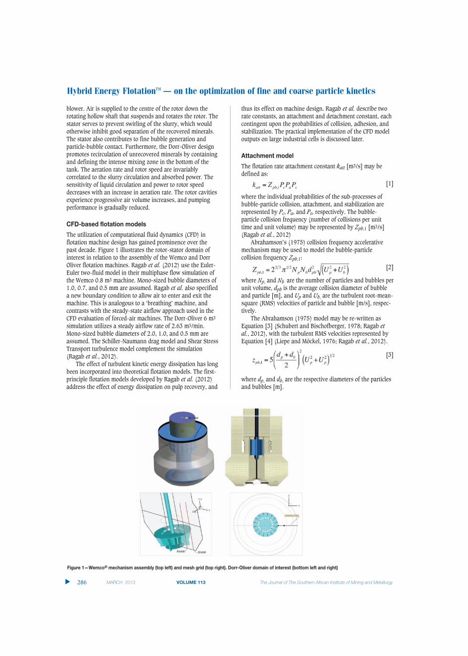
The utilization of computational fluid dynamics (CFD) inflotation machine design has gained prominence over thepast decade. Figure 1 illustrates the rotor-stator domain ofinterest in relation to the assembly of the Wemco and DorrOliver flotation machines. Ragab et al. (2012) use the Euler-Euler two-fluid model in their multiphase flow simulation ofthe Wemco 0.8 m3 machine. Mono-sized bubble diameters of1.0, 0.7, and 0.5 mm are assumed. Ragab et al. also specifieda new boundary condition to allow air to enter and exit themachine. This is analogous to a ‘breathing’ machine, andcontrasts with the steady-state airflow approach used in theCFD evaluation of forced-air machines. The Dorr-Oliver 6 m3
simulation utilizes a steady airflow rate of 2.63 m3/min.Mono-sized bubble diameters of 2.0, 1.0, and 0.5 mm areassumed. The Schiller-Naumann drag model and Shear StressTransport turbulence model complement the simulation(Ragab et al., 2012).
The effect of turbulent kinetic energy dissipation has longbeen incorporated into theoretical flotation models. The first-principle flotation models developed by Ragab et al. (2012)address the effect of energy dissipation on pulp recovery, and
thus its effect on machine design. Ragab et al. describe tworate constants, an attachment and detachment constant, eachcontingent upon the probabilities of collision, adhesion, andstabilization. The practical implementation of the CFD modeloutputs on large industrial cells is discussed later.
Attachment model
The flotation rate attachment constant katt [m3/s] may bedefined as:
[1]
where the individual probabilities of the sub-processes ofbubble-particle collision, attachment, and stabilization arerepresented by Pc, Pa, and Ps, respectively. The bubble-particle collision frequency (number of collisions per unittime and unit volume) may be represented by Zpb,1 [m3/s](Ragab et al., 2012)
Abrahamson’s (1975) collision frequency accelerativemechanism may be used to model the bubble-particlecollision frequency Zpb,1:
[2]
where Np, and Nb are the number of particles and bubbles perunit volume, dpb is the average collision diameter of bubbleand particle [m], and Up and Ub, are the turbulent root-mean-square (RMS) velocities of particle and bubble [m/s], respec-tively.
The Abrahamson (1975) model may be re-written asEquation [3] (Schubert and Bischofberger, 1978; Ragab etal., 2012), with the turbulent RMS velocities represented byEquation [4] (Liepe and Möckel, 1976; Ragab et al., 2012).
[3]
where dp, and db, are the respective diameters of the particlesand bubbles [m].
�
286 MARCH 2013 VOLUME 113 The Journal of The Southern African Institute of Mining and Metallurgy
Figure 1—Wemco® mechanism assembly (top left) and mesh grid (top right). Dorr-Oliver domain of interest (bottom left and right)

[4]
where ∈ is the dissipation rate of the turbulent kinetic energyper unit mass [W/kg], v is the kinematic viscosity of the fluid[m2/s], ρf is the fluid density [kg/m3], ρp is the particledensity [kg/m3] and di is the particle diameter [m]. Theprobability of bubble-particle collision is represented by(Yoon and Luttrell, 1989; Koh and Schwarz, 2006; Ragab etal., 2012):
[5]
where the bubble Reynolds number is defined by Reb =dbUb/v. The probability of adhesion may be expressed asEquation [6] (Yoon and Luttrell, 1989; Koh and Schwarz,2006; Ragab et al., 2012):
[6]
where tind = θ75dp
0.6 (Koh and Smith, 2011; Ragab et al., 2012;Dai et al., 1999) is the induction time [s] and θ = thebubble-particle contact angle [degrees]. Induction time maybe defined as the time required for liquid film thinning anddrainage to occur between a hydrophobic particle and airbubble (Koh and Smith, 2011).
Ragab et al. (2012) utilize the modified Schulze (1993)expression (Bloom and Heindel, 2003) to evaluate thestabilization probability:
[7]
where Bo* is the modified Bond number defined by Equation[8] (Koh and Schwarz, 2006; Ragab et al., 2012) as:
[8]
where As = 0.5 (Bloom and Heindel, 2003), σ is the surfacetension [N/m], Δρ = ρp − ρf, and g is the gravitationalconstant [m/s2].
Detachment model
The bubble-particle detachment rate constant kdet [s-1] maybe defined by Equation [9] (Koh and Schwarz, 2006; Ragabet al., 2012):
[9]
where Zpb,2 is the detachment frequency [s-1], Pd is theprobability of detachment, and has an assumed equivalenceto 1− Ps. (Bloom and Heindel, 2003; Ragab et al., 2012)define the detachment frequency as:
[10]
where C1 =2 is an empirical constant.
CFD-based pulp recovery ate
In Figure 2 the effects of particle diameter (dp), particlespecific gravity (γp), contact angle (θ ), and surface tension(σ ) on the recovery rate constant were evaluated in a Wemcotwo-phase CFD-based model developed by Ragab et al.,(2012).
The attachment and detachment models presented hereindicate that both these sub-processes are affected by theturbulent energy dissipation rate. Therefore, the netattachment rate will be contingent upon the energydissipation rate management. Schubert (1989, 2008) definesthe mean energy dissipation rate ε as the ratio of the totalspecific power input M [W] to the overall slurry mass [kg](Equation [11]).
[11]
This macro relationship assumes consistenthydrodynamic conditions throughout the cell. A multipliermay be used to relate the local rotor-disperser power input tothat of the total slurry mass, but with no spatial distributionof the energy dissipation rate, the effect of hydrodynamics onthe local net attachment rate and kinetic rate is unknown(Schubert, 2008; Ragab et al., 2012). Deglon (2005) andGrano (2005) also suggest the need for an optimum powerinput to mechanically agitated flotation machines. TheWemco 0.8 m3 CFD-based model yields the local recovery rate
Hybrid Energy Flotation™ – on the optimization of fine and coarse particle kinetics
287The Journal of The Southern African Institute of Mining and Metallurgy VOLUME 113 MARCH 2013 �
Figure 2—Wemco local attachment (left) and detachment (right) rates for dp = 100 μm; γp = 4.1; θ = 40°; σ = 0.06 mN ; db = 0.7 mm
Hybrid Energy Flotation™ – on the optimization of fine and coarse particle kinetics
constant as one of the outputs, and may therefore be usedboth as a process optimization and flotation machine designtool (Ragab et al., 2012).
Understanding the interaction between particle diameter,local energy dissipation rate, contact angle, and local airfraction on local attachment rates is integral to flotationmachine design, setup, and operation. Ragab et al. (2012)define the average pseudo pulp recovery rate k1a
* in Equation [12]:
[12]
where Rf = 1 is the froth recovery factor and β = 0. Koh andSchwarz (2006) define β as a bubble loading parameterwhere β = 1 for fully loaded bubbles and β = 0 for cleanbubbles. The recovery rate constant k1
* is defined as:
[13]
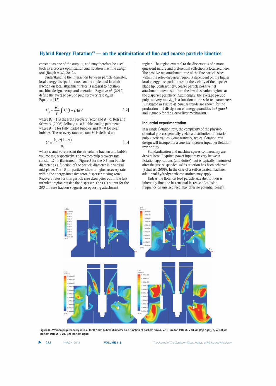
where α and υb represent the air volume fraction and bubblevolume m3, respectively. The Wemco pulp recovery rateconstant k1
* is illustrated in Figure 3 for the 0.7 mm bubblediameter as a function of the particle diameter in a verticalmid-plane. The 10 μm particles show a higher recovery ratewithin the energy-intensive rotor-disperser mixing zone.Recovery rates for this particle size class peter out in the lessturbulent region outside the disperser. The CFD output for the200 μm size fraction suggests an opposing attachment
regime. The region external to the disperser is of a morequiescent nature and preferential collection is localized here.The positive net attachment rate of the fine particle sizeswithin the rotor-disperser region is dependent on the higherlocal energy dissipation rates in the vicinity of the impellerblade tip. Contrastingly, coarse particle positive netattachment rates result from the low dissipation regions atthe disperser periphery. Additionally, the average pseudopulp recovery rate k1
*a is a function of the selected parameters
(illustrated in Figure 4). Similar trends are shown for theproduction and dissipation of energy quantities in Figure 5and Figure 6 for the Dorr-Oliver mechanism.
Industrial experimentation
In a single flotation row, the complexity of the physico-chemical process generally yields a distribution of flotationpulp kinetic values. Comparatively, typical flotation rowdesign will incorporate a consistent power input per flotationrow or duty.
Standardization and machine spares commonality aredrivers here. Required power input may vary betweenflotation applications (and duties), but is typically minimizedafter the just-suspended solids criterion has been achieved(Schubert, 2008). In the case of a self-aspirated machine,additional hydrodynamic constraints may apply.
Unless the flotation feed particle size distribution isinherently fine, the incremental increase of collisionfrequency on unsized feed may offer no potential benefit.
�
288 MARCH 2013 VOLUME 113 The Journal of The Southern African Institute of Mining and Metallurgy
Figure 3—Wemco pulp recovery rate k1* for 0.7 mm bubble diameter as a function of particle size dp = 10 μm (top left), dp = 40 μm (top right), dp = 100 μm
(bottom left), dp = 200 μm (bottom right)

Hybrid Energy Flotation™ – on the optimization of fine and coarse particle kinetics
The Journal of The Southern African Institute of Mining and Metallurgy VOLUME 113 MARCH 2013 289 �
Figure 4—Wemco average pulp flotation rate k1*a as a function of contact angle and bubble size (0.5 mm (top left), 0.7 mm (top right), and 1.0 mm (bottom))
Figure 5—Dorr-Oliver pulp recovery rate k1* for 1.0 mm bubble diameter as a function of particle size dp = 10 μm (top left), dp = 40 μm (top right), dp = 100
μm (bottom left), dp = 200 μm (bottom right)

Hybrid Energy Flotation™ – on the optimization of fine and coarse particle kinetics
Grano (2006) and Deglon (1998) have shown that therecovery in the coarse size range is typically negated by theincrease in turbulent energy dissipation.
Coarse particle recovery tends to be inhibited by thepredominance of turbulence in a mechanical flotation cell(Jameson, 2010), possible surface tension effects (Sherrell and Yoon, 2005) and the froth recovery component. Schubert(2008) suggests that pre-classification of the flotation feedinto fine and coarse streams offers independent treatment ofthe size fractions. Power (or machine hydrodynamics) shouldbe individually optimized to maintain solids suspension inthe coarse stream, and maximize collision frequency in itsfiner counterpart (Schubert, 2008). However, Ata et al.(2012) contend that the presence of fines provides thenecessary froth stability to propagate coarse particle recovery.Therefore, turbulence management of an unclassified feed ina single row may be the preferred method of implementation.
The application of turbulent dissipation energymanagement manifests itself in the Hybrid EnergyFlotation™ technology specific to the distribution of valuableminerals in the flotation feed. CFD-based models suggest thatinherently fine distributions should benefit from higherpower inputs. Valuable mineral distributions skewed towardthe coarser range favour a lower rate of energy dissipation. Ingeneral, recovery-by-size distributions are more normal innature. Therefore, valuable mineral recovery resulting from adistribution of power input within a single row appears to offer a metallurgical design of greater specificity. Thisstrategy also suggests a shift away from the old orthodoxy ofa residence time-constrained flotation row to a customizedturbulence-distribution metallurgical design. The applicationof the Hybrid Energy Flotation™ technology in bulk copper-molybdenite flotation duties is now discussed.
Results and discussion
Case one
The first case study involves a porphyry copper rougher-scavenger row comprising 5 x 257 m3 Wemco machines. Eachmachine was initially equipped with standard installed powerand operated at standard rotor speeds. An atypical differencebetween laboratory and full-scale molybdenite recoveriesevolved into a simple laboratory-scale investigation into the
effect of bulk turbulent dissipation energy on molybdeniterecovery. An initial liquid residence time distributionevaluation of the five-cell row yielded no signs of short-circuiting (Figure 7).
The ratio of experimental to theoretical residence timesranged from 1.01 to 1.10 (Govender, 2010). A typical ratio of1±0.1 is indicative of well-mixed vessels. The curve shape,characterized by the absence of an early, sharp peak isindicative of no short-circuiting. Additionally, the lack of along, drawn-out tails section typifies a mixing vessel devoidof stagnant or dead volume (Govender, 2010). Thereafter,site personnel tested the effect of additional residence time bytemporarily converting existing 8.5 m3 cleaner cells intoscavenger duty units. The scavenger tails process stream wasthen re-routed to these machines to evaluate the effect of theadditional residence time on unsized recovery. Table Ihighlights the measured scavenger-stage recovery response.The associated recovery variance is typical of scavenger dutyindustrial-scale evaluations. Figure 8 also suggested that themolybdenite recovery rate was tied to the residence time. The
�
290 MARCH 2013 VOLUME 113 The Journal of The Southern African Institute of Mining and Metallurgy
Figure 7—Liquid tracer test residence time distribution (measured vs.fitted)
Figure 6—Dorr-Oliver average pulp flotation rate k1*a as a function of contact angle and bubble size (0.5 mm (left) and 1.0 mm (right))

correlation coefficient between the throughput and recoverydatasets is -0.64, indicating a fairly strong inverserelationship.
The flotation rate of molybdenite in porphyry copperapplications, which often lags that of copper (Zanin et al.,2009), has been shown to improve significantly withincreased specific power input. Molybdenite flotation kinetics,and its response to power input, may be attributed to theplatelet shape of molybdenite particles produced via specificfragmentation mechanisms (Zanin et al., 2009). Theresulting shape factor may result in a flotation rate responsethat is more amenable to increased collision frequency (Zaninet al., 2009). The response to collision frequency is thereforesimilar to that theorized for fine particle flotation.
Schubert (2008) concludes that collision frequency ispositively correlated to the energy dissipation rate (εR) in therotor-stator region, while exhibiting an inverse relationshipto the fluid viscosity (v). Consequentially, Schubert maintainsthat a maximal εR/v ratio is beneficial to fine particleflotation.
Figure 9 illustrates the size-by-size distribution of themonthly tailings composites. Both copper and molybdenitelosses are visibly skewed towards the fine fraction. Utilizinga laboratory-scale randomized-block 22 factorial experimentdesign, the effect of feed slurry density on molybdenite andcopper recovery is presented in Figure 10. The randomizedtest runs and two-level factorial design set-points aresummarized in Table II. Each of the test samples was sub-sampled from a composite feed sample. The solids concen-tration target was achieved by concentration or process water
dilution of the primary feed. Rotor speed was confirmed witha tachometer. The qualitative slurry density scale isrepresented by two factor levels: ‘low’ = 24 wt% and ‘high’ =35 wt% feed solids concentration. The effect of rotor speedonly was not significant at the 95 per cent confidence limit,and therefore the average value is utilized in the solidsconcentration evaluation. Overall molybdenite recoveryincreased markedly with the 11 per cent absolute decrease insolids concentration, and the effect is statistically significant.
Copper recovery illustrates a contradictory relationshipbut, statistically, no effect is observed due to the overlappingof the confidence bands at the high and low density levels. Itis still probable that the net copper attachment rate wasadversely affected with the increase in turbulent energydissipation.
In a similar evaluation, Zanin et al. (2009) noticed aninverse correlation between molybdenite recovery and feedsolids concentration. This was attributed partially to the
Hybrid Energy Flotation™ – on the optimization of fine and coarse particle kinetics
The Journal of The Southern African Institute of Mining and Metallurgy VOLUME 113 MARCH 2013 291 �
Table I
Effect of additional residence time on scavengerstage recovery
Species No. of samples Additional recovery (%)
Average (%) Standard deviation (%)
Cu 6 14.6 13.2Mo 6 12.9 9.1
Figure 8—Effect of residence time on molybdenite recovery (daily averages)
Figure 9—Size-by-size distribution of Cu (left) and MoS2 (right) in rougher-scavenger tails

Hybrid Energy Flotation™ – on the optimization of fine and coarse particle kinetics
increased collision frequency borne out of the reduction influid viscosity. In Figure 11 MoS2 recovery is plotted as afunction of the interaction of rotor speed and viscosity(inferred from solids concentration). At low rotor speeddesign levels, the recovery response lags the average; theopposite relationship applies at the high rotor speed level.Therefore, in manipulating the macro turbulent local energydissipation rate and/or slurry viscosity, the net attachmentrate increased. Consequentially, a positive response in MoS2overall recovery was observed.
The effect of increased turbulence on the concentrategrade response was also evaluated on a laboratory-scalebasis (Figure 12). Low-level solids feed concentrations havedistinct gangue entrainment reduction benefits. This datasubset visually indicates a superior grade-recovery curve atthe high-level rotor speed condition.
Upon confirmation of the energy dissipation-recoveryeffect, the penultimate cell in the five-cell rougher-scavengerrow was enabled with a larger installed motor capacity, andthe specific power input increased via a variable-frequencydrive (actual plant feed could not be diluted due to processwater constraints). Froth depth was simultaneously increasedto negate gangue entrainment. The increase in rotor speedwas constrained by the installed motor power, butmolybdenite row recovery showed no optimum in the testedrotor speed range i.e. there was no indication of a decrease inthe net attachment rate with an increase in power input.Figure 13 illustrates the recovery responses of the plant-scaletrial. Stage recoveries (on a relative basis) illustrate a loose,positive response to power input. The final two cells in therougher-scavenger row were then changed to a constant,maximum rotor speed operational condition.
�
292 MARCH 2013 VOLUME 113 The Journal of The Southern African Institute of Mining and Metallurgy
Figure 11—Laboratory-scale MoS2 recovery response to the feed solids concentration and rotor speed interaction. The circular design data pointsrepresent the low rotor speed condition (left), and are compared to the high rotor speed condition (right)
Figure 10—Effect of solids concentration on MoS2 (left) and Cu (right) recovery
Table II
Factorial design set-points (per test run order)
Test ID Rotor speed (r/min) Solids concentration (%w/w)
S13 1455 (H) 24 (L)S14 1200 (L) 24 (L)S15 1200 (L) 35 (H)S16 1455 (H) 35 (H)
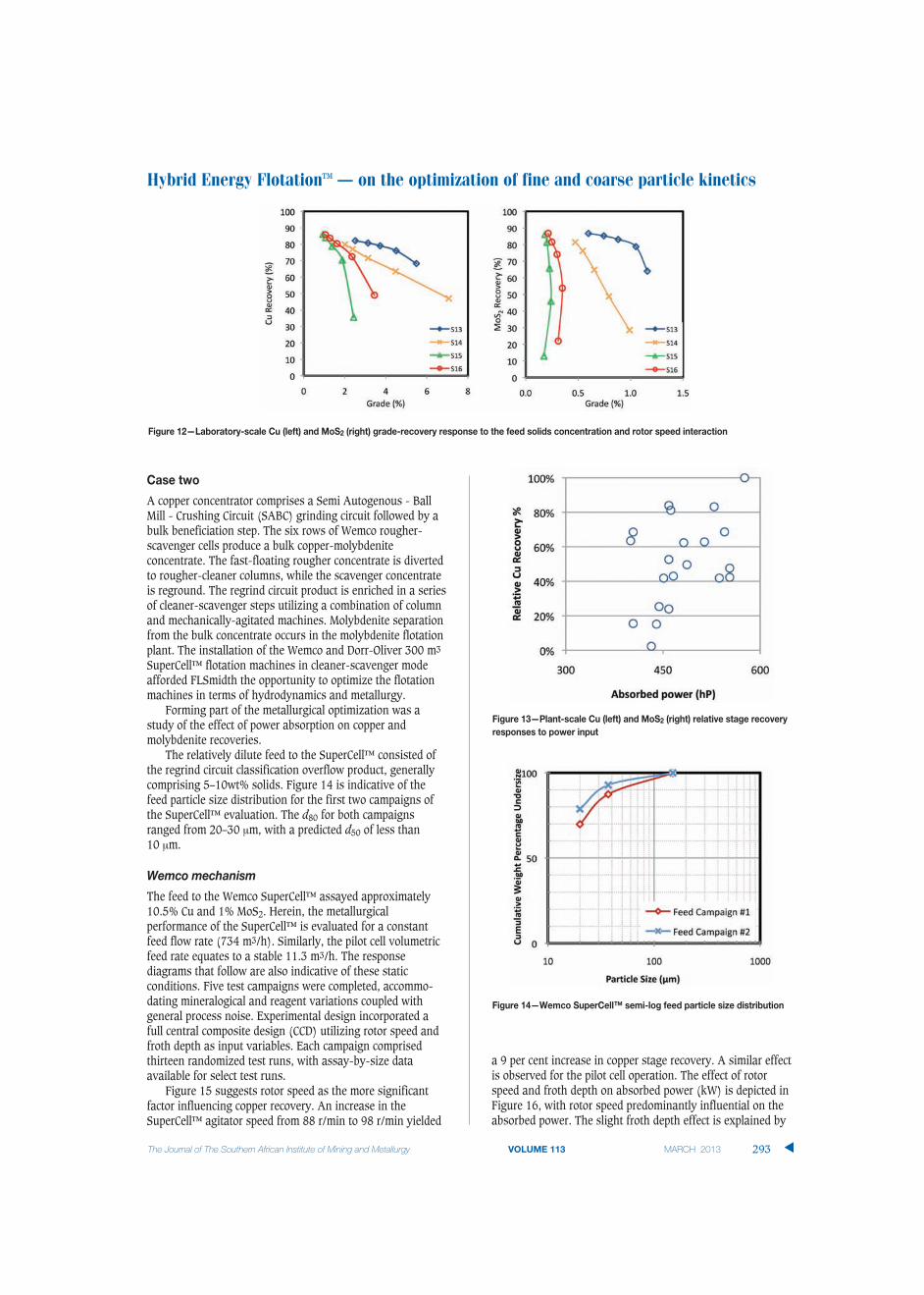
Case two
A copper concentrator comprises a Semi Autogenous - BallMill - Crushing Circuit (SABC) grinding circuit followed by abulk beneficiation step. The six rows of Wemco rougher-scavenger cells produce a bulk copper-molybdeniteconcentrate. The fast-floating rougher concentrate is divertedto rougher-cleaner columns, while the scavenger concentrateis reground. The regrind circuit product is enriched in a seriesof cleaner-scavenger steps utilizing a combination of columnand mechanically-agitated machines. Molybdenite separationfrom the bulk concentrate occurs in the molybdenite flotationplant. The installation of the Wemco and Dorr-Oliver 300 m3
SuperCell™ flotation machines in cleaner-scavenger modeafforded FLSmidth the opportunity to optimize the flotationmachines in terms of hydrodynamics and metallurgy.
Forming part of the metallurgical optimization was astudy of the effect of power absorption on copper andmolybdenite recoveries.
The relatively dilute feed to the SuperCell™ consisted ofthe regrind circuit classification overflow product, generallycomprising 5–10wt% solids. Figure 14 is indicative of thefeed particle size distribution for the first two campaigns ofthe SuperCell™ evaluation. The d80 for both campaignsranged from 20–30 μm, with a predicted d50 of less than 10 μm.
Wemco mechanism
The feed to the Wemco SuperCell™ assayed approximately10.5% Cu and 1% MoS2. Herein, the metallurgicalperformance of the SuperCell™ is evaluated for a constantfeed flow rate (734 m3/h). Similarly, the pilot cell volumetricfeed rate equates to a stable 11.3 m3/h. The responsediagrams that follow are also indicative of these staticconditions. Five test campaigns were completed, accommo-dating mineralogical and reagent variations coupled withgeneral process noise. Experimental design incorporated afull central composite design (CCD) utilizing rotor speed andfroth depth as input variables. Each campaign comprisedthirteen randomized test runs, with assay-by-size dataavailable for select test runs.
Figure 15 suggests rotor speed as the more significantfactor influencing copper recovery. An increase in theSuperCell™ agitator speed from 88 r/min to 98 r/min yielded
a 9 per cent increase in copper stage recovery. A similar effectis observed for the pilot cell operation. The effect of rotorspeed and froth depth on absorbed power (kW) is depicted inFigure 16, with rotor speed predominantly influential on theabsorbed power. The slight froth depth effect is explained by
Hybrid Energy Flotation™ – on the optimization of fine and coarse particle kinetics
The Journal of The Southern African Institute of Mining and Metallurgy VOLUME 113 MARCH 2013 293 �
Figure 12—Laboratory-scale Cu (left) and MoS2 (right) grade-recovery response to the feed solids concentration and rotor speed interaction
Figure 13—Plant-scale Cu (left) and MoS2 (right) relative stage recoveryresponses to power input
Figure 14—Wemco SuperCell™ semi-log feed particle size distribution

Hybrid Energy Flotation™ – on the optimization of fine and coarse particle kinetics
the apparent change in submergence. The average absorbedpower of the SuperCell™ ranged from about 190 kW to 270 kW, translating into a 0.6–0.9 kW/m3 specific powerrange. Power absorption of the pilot cell ranged from 1.8 kWto 2.0 kW or a 1.2–1.3 kW/m3 specific power range.
Grano (2006), Schubert (2008), and Deglon (1998)report that the effect of power or agitation on recovery on anunsized basis is less likely to be observed, due to fine particlerecovery improvements being offset by the decrease inattachment efficiency of the coarser particle size fraction. Thisis further corroborated by Equation [10]. With a minorcontribution from the coarse particle size fraction in theclassified regrind mill product, the unsized SuperCell™ feedmaterial could still be construed as fine. But, if the copperand molybdenite sub-20 μm size class recoveries are plottedas a function of the absorbed power (Figure 17), the fine-particle recovery-power relationship becomes visuallyprominent.
Figure 17 suggests that the fine particle recovery deficitcommonly observed in base metals operations may be offsetby increasing the impeller speed of mechanically-agitatedmachines. An additional contributory effect is expected tohave been provided by the dilute feed (Schubert, 2008).
The development of statistically significant hydrodynamicand metallurgical models for the Wemco SuperCell™ allowedfor the more detailed study of the effect of absorbed power on
metallurgical performance of the cell. Table III showsoptimum operational conditions required to maximize copperand molybdenite recoveries at a fixed concentrate grade. Forthe purpose of this exercise, metallurgical characteristics ofthe feed were maintained at average conditions (aspreviously described) and volumetric feed flow input was setto 681 m3/h. With an increase in specific power from 0.74 to0.84 kW/m3, the tabulated data exhibits an increase in the
�
294 MARCH 2013 VOLUME 113 The Journal of The Southern African Institute of Mining and Metallurgy
Figure 17—Wemco Cu and MoS2 recovery of sub-20 �m fraction
Figure 16—Absorbed power (kW) response surface for the Wemco SuperCell™ (left) and the pilot cell (right)
Figure 15—Cu recovery (%) response surface for the Wemco SuperCell™ (left) and the pilot cell (right) developed for the ore type treated in secondcampaign

expected copper and molybdenite recovery responses of 2.7per cent and 3.1 per cent, respectively. The recoveryresponses are constrained by a minimum copper concentrategrade requirement (28 per cent). The improvement inmetallurgical performance cannot be explained by animproved higher air flow number as the value of this variableremains fairly constant. Thus, presented data stronglysupports the energy dissipation response shown in the CFDmodel outputs.
Dorr-Oliver mechanism
The Dorr-Oliver mechanism was subject to a similar multi-campaign CCD experimental design. The experimental factorsincluded rotor speed, froth depth, and air flow as inputvariables. Each campaign comprised twenty-one randomizedtest runs, with assay-by-size data available for select testruns. Figure 18 compares copper and molybdenite recoveryresponses as a function of size-by-size recovery and impellerrotational speed. This dataset forms a subset of the overallexperimental design evaluation, and relates the recoveryresponse to the impeller speed effect (Table IV).
Figure 18 corroborates the expected responses from theDorr-Oliver CFD-based model, although there is no statisticalsignificance in the differences between the two rotor speedsettings. The lack of significance stems from utilizing a datasubset that covers a wide range of operational conditionsover multiple campaigns. The solution lies in running adedicated randomized-block experiment to improve thesensitivity of the rotor speed effect. This suggestion ispredicated upon the assumption that test runs made closertogether are likely to be of greater similitude than runs madefurther apart.
Conclusions
Theoretical flotation models indicate that both the attachmentand detachment sub-processes are affected by turbulentdissipation energy. The multiphase CFD model developed byRagab et al. (2012) utilizes local turbulent energy dissipationand gas hold-up values, in conjunction with particle, specificgravity, liquid surface tension, and contact angle parametersto estimate the local pulp recovery rate. The CFD modelsindicate that preferential pulp collection zones in the Wemcoand Dorr-Oliver flotation machines may vary with size class
Hybrid Energy Flotation™ – on the optimization of fine and coarse particle kinetics
The Journal of The Southern African Institute of Mining and Metallurgy VOLUME 113 MARCH 2013 295 �
Table III
Summary of metallurgical evaluation
Specific power Pumping rate Induced airflow Copper grade Copper recovery Molybdenite recovery (kW/m3) (m3/min) (m3/min) response (%) response (%) response (%)
Scenario 1 0.74 185 35.1 28.0 86.0 82.9Scenario 2 0.79 187 35.4 28.0 87.5 84.5Scenario 3 0.84 195 34.0 28.0 88.7 86.0
Table IV
Dorr-Oliver CCD experimental design data subset
No. of Rotor peed Mean absorbed Standard deviation- Mean - airflow Standard deviation - Mean- froth Standard deviation -
observations (r/min) power (kW) power (kW) (m3/min) airflow (m3/min) depth (inch) froth depth (inch)
4 69 86 4 39 8.1 17.1 10.3
7 82 133 10 40.7 4.1 21.9 8.5
Figure 18—Dorr-Oliver Cu (left) and MoS2 (right) recovery as a function of particle size and impeller speed. Average feed distribution is compared on thebar chart (secondary axis)

Hybrid Energy Flotation™ – on the optimization of fine and coarse particle kinetics
due to the local turbulent kinetic energy dissipation. Themodel responses also suggest that the attachment rate of thefine fraction increases in the high-energy zones shrouded bythe stator/disperser and adjacent to the impeller tip. While itappears that fine particle flotation kinetics was enhancedwith increasing energy dissipation, it is surmised that coarseparticle recovery is affected by the detachment sub-process,as induced by the adverse susceptibility to increased fluidturbulence. Coarse particle flotation was therefore favoured inregions of lower energy dissipation.
The flotation rate of molybdenite in porphyry copperapplications, which often lags that of copper (Zanin et al.,2009), has been shown to improve significantly withincreased specific power input. Molybdenite flotation kinetics,and its response to power input, may be attributed to theplatelet shape of molybdenite particles produced via specificfragmentation mechanisms (Zanin et al., 2009). Theresulting shape factor may result in a flotation rate responsethat is more amenable to increased collision frequency. Thisresult was replicated on a laboratory scale for rougher feed.Statistically, copper recovery showed no effect.
The metallurgical evaluation of the 300 m3 Wemco andDorr-Oliver mechanisms suggested that preferential collectionof fine and coarse particles could be achieved by appropriatemanagement of the local turbulent dissipation energy. Properexperimental design is recommended to achieve greaterconfidence in industrial-scale testing of this effect.
Hybrid Energy Flotation™ rows offer optimized collisionfrequencies via a distribution of energy dissipation values.Experimental work utilizing typical porphyry copper bulkfeeds indicates that this approach may offer potentialrecovery benefits for individual size classes. The applicationof Hybrid Energy Flotation™ offers the opportunity tooptimize metallurgical performance of a single row throughideal management of local energy dissipation in relation tothe valuable mineral distribution in the feed. This approachalludes to a shift away from the traditional residence timerequirements that constrain flotation circuit design.
References ABRAHAMSON, J. 1975. Collision rates of small particles in a vigorously turbulent
fluid. Chemical Engineering Science, vol. 30, pp. 1371–1379.
ATA, S., RAHMAN, R.M., AND JAMESON, G.J. 2012. The effect of flotation variables
on the recovery of different particle size fractions in the froth and the pulp.
International Journal of Mineral Processing, vol. 106–109,
pp. 70–77.
BLOOM, F. and HEINDEL, T.J. 2002. On the structure of collision and detachment
frequencies in flotation models. Chemical Engineering Science, vol. 57.
pp. 2467-–2473.
DAI, Z., FORNASIERO, D., and RALSTON, J. 1999. Particle–bubble attachment in
mineral flotation. Journal of Colloid and Interface Science, vol. 217, no. 1.
pp. 70–76.
DEGLON, D.A. 1998. A hydrodynamic investigation of fine particle flotation in a
batch flotation cell. PhD thesis, University of Cape Town, South Africa.
DEGLON, D.A. 2005. The effect of agitation on the flotation of platinum ores.
Minerals Engineering, vol. 18. pp. 839–844.
GOVENDER, D. 2010. Mineral Park – an evaluation into the liquid phase
residence time distribution of the Wemco 257m3 rougher-scavenger
circuit. Internal Report, FLSmidth Salt Lake City Inc.
GRANO, S. 2006. Effect of impeller rotational speed on the size dependent
flotation rate of galena in full scale plant cells. Minerals Engineering,
vol. 19. pp. 1307–1318.
JAMESON, G.J. 2010. New directions in flotation machine design. Minerals
Engineering, vol. 23. pp. 835–841.
KOH, P.T.L. and SCHWARZ, M.P. 2006. CFD modelling of bubble-particle
attachments in flotation cells. Minerals Engineering, vol. 19. pp. 619–626.
KOH, P.T.L. AND SMITH, L.K. 2011. The effect of stirring speed and induction
time on flotation. Minerals Engineering, vol. 24. pp. 442–448.
LIEPE, F. and MÖCKEL, H-O. 1976. Untersuchungen zum stoffvereinigen in
flüssiger phase. Chemical Technology, vol. 30. pp. 205–209.
RAGAB, S.A. and FAYED, H. 2012. Collision frequency of particles and bubbles
suspended in homogeneous isotropic turbulence. AIAA Paper 2012-0310.
AIAA 50th Aerospace Sciences Meeting, Nashville, TN, 9–12 January
2012.
SCHUBERT, H. 1989. The role of turbulence in mineral processing unit
operations. Challenges in Mineral Processing. Sastry, K. and Fuerstenau.
M.C. (eds.). SME Inc., Littleton, CO. pp. 272–289.
SCHUBERT, H. 2008. On the optimization of hydrodynamics in fine particle
flotation,. Minerals Engineering, vol. 21. pp. 930–936.
SCHUBERT, H. and BISCHOFBERGER, C. 1978. On the hydrodynamics of flotation
machines. International Journal of Mineral Processing, vol. 5.
pp. 131–142.
SCHULZE, H. 1993. Flotation as a heterocoagulation process: possibilities of
calculating the probability of flotation. Coagulation and Flocculation:
Theory and Applications. Dobiáš, B. (ed.). Marcel Dekker, New York.
pp 321-363.
SHERRELL, I. and YOON, R-H. 2005. Development of a turbulent flotation model.
Proceedings of the Centenary of Flotation Symposium 2005. The
Australian Institute of Mining and Metallurgy, Brisbane. pp 611.
YOON, R.H. and LUTTRELL, G.H. 1989. The effect of bubble size on fine particle
flotation. Frothing and Flotation. Laskowski, J. (ed.). (Gordon & Breach,
New York. pp. 101–122.
ZANIN, M., AMETOV, I., GRANO S., ZHOU, L., and SKINNER, W. 2009. A study of
mechanisms affecting molybdenite recovery in a bulk copper/molybdenum
flotation circuit. International Journal of Mineral Processing, vol. 93.
pp. 256–266. �
�
296 MARCH 2013 VOLUME 113 The Journal of The Southern African Institute of Mining and Metallurgy