hybrid portable hf antenna (cha hybrid - mini /...
TRANSCRIPT
Hybrid Portable HF Antenna
(CHA HYBRID - MINI / MICRO)
Operator’s Manual
California - USA
WWW.CHAMELEONANTENNA.COM
VERSATILE – DEPENDABLE – STEALTH – BUILT TO LAST
CHA HYBRID - MINI / MICRO Page 2
CHA HYBRID - MINI / MICRO Page 3
Table of Contents
Introduction .............................................................................................................................................. 4
HF Propagation ......................................................................................................................................... 4
Parts of the Antenna ................................................................................................................................. 5
Antenna Configurations ............................................................................................................................ 7
Horizontal NVIS ..................................................................................................................................... 8
Sloping Wire .......................................................................................................................................... 9
Inverted “L” ......................................................................................................................................... 10
Manpack Vertical ................................................................................................................................ 12
Portable Vertical ................................................................................................................................. 13
High Efficiency Portable Vertical ......................................................................................................... 14
Tilted NVIS ........................................................................................................................................... 15
Portable Dipole ................................................................................................................................... 16
Recovery Procedure ................................................................................................................................ 17
Troubleshooting ...................................................................................................................................... 18
Specifications .......................................................................................................................................... 18
Accessories .............................................................................................................................................. 23
Chameleon AntennaTM Products ............................................................................................................ 24
References .............................................................................................................................................. 26
Be aware of overhead power lines when you are deploying the CHA HYBRID - MINI / MICRO antenna
system. You could be electrocuted if the antenna gets near or contacts overhead power lines.
All information on this product and the product itself is the property of and is proprietary to Chameleon
AntennaTM. Specifications are subject to change without prior notice.
CHA HYBRID - MINI / MICRO Page 4
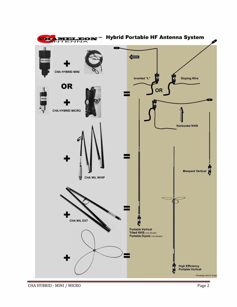
Introduction Thank you for purchasing and using the Chameleon AntennaTM Hybrid - Mini / Micro Portable High Frequency (HF)
Antenna (CHA HYBRID-MINI or CHA HYBRID-MICRO). The CHA HYBRID - MINI / MICRO antenna system is designed
to be the most versatile, high performance, and rugged portable / manpackable HF antenna available - similar to
those used by armies worldwide. The base system is comprised of, either a CHA HYBRID-MINI or CHA HYBRID-
MICRO portable base and 60 feet of wire. Available system options (sold separately) include a 10’8” military-style
collapsible whip antenna (CHA MIL WHIP), a 6’6” collapsible extension (CHA MIL EXT), and a high efficiency
capacity hat (CHA CAP HAT). The components of the CHA HYBRID - MINI / MICRO antenna system provide a
continuum of portability and performance to meet your communications requirements. Operators that already
have a CHA V1, V1L, or V2L mobile whip can also use them with the CHA HYBRID - MINI / MICRO base, although
the MINI and MICRO bases are for stationary use only. You can even combine a CHA HYBRID - MINI / MICRO base
with two CHA MIL whips, two CHA MIL EXT whip extensions, and a Chameleon AntennaTM Jaw Mount and Tripod to
create a 34’6” portable horizontal dipole. The integral broadband impedance matching network transformer
allows broadband antenna tuning. The antenna will operate from 1.8 - 54 MHz (including 160m – 6m amateur
bands) without any adjustment with a wide range antenna tuner (the shortest configuration has limited
performance below 3.5 MHz). The CHA HYBRID - MINI / MICRO is perfect for military, government agencies, non-
governmental organizations (NGOs), Military Affiliate Radio System (MARS), Civil Air Patrol (CAP), Amateur Radio
Emergency Service (ARES) / Radio Amateur Civil Emergency Service (RACES), Salvation Army Team Emergency
Radio Network (SATERN), First Responders and especially for Emergency Preparedness. It is also the antenna for
hams that enjoy camping and hiking or those living in apartments and condominiums or developments with
homeowners associations, deed restrictions, or CCRs (Covenants, Conditions & Restrictions). The CHA HYBRID -
MINI / MICRO is configurable to facilitate Near-Vertical Incident Sky wave (NVIS) communication and is totally
waterproof. The CHA HYBRID - MINI / MICRO antenna system requires a wide range antenna tuner or coupler.
Antennas built by Chameleon AntennaTM are versatile, dependable, stealthy, and built to last. Please read this
operator’s manual so that you may maximize the utility you obtain from your CHA HYBRID - MINI / MICRO antenna
system.
HF Propagation HF radio provides relatively inexpensive and reliable local, regional, national, and international voice and data
communication capability. It is especially suitable for undeveloped areas where normal telecommunications are
not available, too costly or scarce, or where the commercial telecommunications infrastructure has been damaged
by a natural disaster or military conflict.
Although HF radio is a reasonably reliable method of communication, HF radio waves propagate through a
complex and constantly changing environment and are affected by weather, terrain, latitude, time of day, season,
and the 11-year solar cycle. A detailed explanation of the theory of HF radio wave propagation is beyond the
scope of this operator’s manual, but an understanding of the basic principles will help the operator decide what
frequency and which of the CHA HYBRID - MINI / MICRO configurations will support their communication
requirements.
HF radio waves propagate from the transmitting antenna to the receiving antenna using two methods: ground
waves and sky waves.
Ground waves are composed of direct waves and surface waves. Direct waves travel directly from the transmitting
CHA HYBRID - MINI / MICRO Page 5
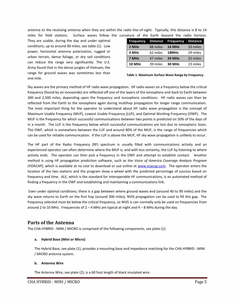
antenna to the receiving antenna when they are within the radio line-of-sight. Typically, this distance is 8 to 14
miles for field stations. Surface waves follow the curvature of the Earth beyond the radio horizon.
They are usable, during the day and under optimal
conditions, up to around 90 miles, see table (1). Low
power, horizontal antenna polarization, rugged or
urban terrain, dense foliage, or dry soil conditions
can reduce the range very significantly. The U.S.
Army found that in the dense jungles of Vietnam, the
range for ground waves was sometimes less than
one mile.
Frequency Distance Frequency Distance
2 MHz 88 miles 14 MHz 33 miles
4 MHz 62 miles 18MHz 29 miles
7 MHz 47 miles 24 MHz 25 miles
10 MHz 39 miles 30 MHz 23 miles
Table 1. Maximum Surface Wave Range by Frequency.
Sky waves are the primary method of HF radio wave propagation. HF radio waves on a frequency below the critical
frequency (found by an ionosonde) are reflected off one of the layers of the ionosphere and back to Earth between
300 and 2,500 miles, depending upon the frequency and ionospheric conditions. HF radio waves can then be
reflected from the Earth to the ionosphere again during multihop propagation for longer range communication.
The most important thing for the operator to understand about HF radio wave propagation is the concept of
Maximum Usable Frequency (MUF), Lowest Usable Frequency (LUF), and Optimal Working Frequency (OWF). The
MUF is the frequency for which successful communications between two points is predicted on 50% of the days of
in a month. The LUF is the frequency below which successful communications are lost due to ionospheric loses.
The OWF, which is somewhere between the LUF and around 80% of the MUF, is the range of frequencies which
can be used for reliable communication. If the LUF is above the MUF, HF sky wave propagation is unlikely to occur.
The HF part of the Radio Frequency (RF) spectrum is usually filled with communications activity and an
experienced operator can often determine where the MUF is, and with less certainty, the LUF by listening to where
activity ends. The operator can then pick a frequency in the OWF and attempt to establish contact. Another
method is using HF propagation prediction software, such as the Voice of America Coverage Analysis Program
(VOACAP), which is available at no cost to download or use online at www.voacap.com. The operator enters the
location of the two stations and the program show a wheel with the predicted percentage of success based on
frequency and time. ALE, which is the standard for interoperable HF communications, is an automated method of
finding a frequency in the OWF and establishing and maintaining a communications link.
Even under optimal conditions, there is a gap between where ground waves end (around 40 to 90 miles) and the
sky wave returns to Earth on the first hop (around 300 miles). NVIS propagation can be used to fill this gap. The
frequency selected must be below the critical frequency, so NVIS is can normally only be used on frequencies from
around 2 to 10 MHz. Frequencies of 2 – 4 MHz are typical at night and 4 – 8 MHz during the day.
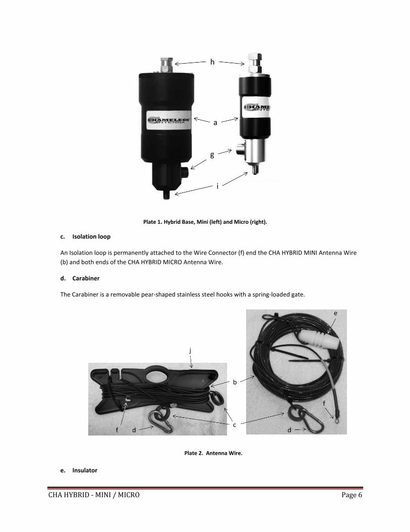
Parts of the Antenna The CHA HYBRID - MINI / MICRO is comprised of the following components, see plate (1):
a. Hybrid Base (Mini or Micro)
The Hybrid Base, see plate (1), provides a mounting base and impedance matching for the CHA HYBRID - MINI
/ MICRO antenna system.
b. Antenna Wire
The Antenna Wire, see plate (2), is a 60 foot length of black insulated wire.
CHA HYBRID - MINI / MICRO Page 6
Plate 1. Hybrid Base, Mini (left) and Micro (right).
c. Isolation loop
An Isolation loop is permanently attached to the Wire Connector (f) end the CHA HYBRID MINI Antenna Wire
(b) and both ends of the CHA HYBRID MICRO Antenna Wire.
d. Carabiner
The Carabiner is a removable pear-shaped stainless steel hooks with a spring-loaded gate.
Plate 2. Antenna Wire.
e. Insulator
CHA HYBRID - MINI / MICRO Page 7
The Insulator is permanently attached to one end of the CHA HYBRID MICRO Antenna Wire (b).
f. Wire Connector
The Wire Connectors are located at one end of the Antenna Wires (b).
g. UHF Socket
The UHF Socket, SO-239, is located on the side of the Hybrid Base (a).
h. Antenna Connection
The Antenna Connection is located on the top of the Hybrid Base (a). It is a 3/8” x 24 (fine thread) female
fitting.
i. Counterpoise Connection
The Counterpoise Connection is located on the bottom of the Hybrid Base (a). It is a 3/8” x 24 (fine thread)
male fitting.
j. Line Winder
The Line Winder is used to store the Antenna Wire (b). It enables rapid deployment and recovery of the CHA
HYBRID MICRO antenna.
k. Antenna Shackle
The Antenna Shackle assembly, see plate (3), consists of a shackle, bolt, and nut. It is attached to the top of
the Hybrid Base (a).
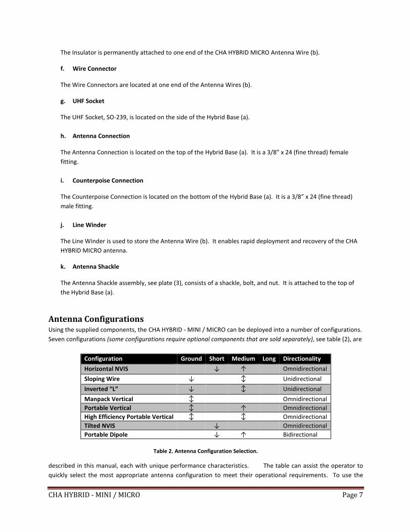
Antenna Configurations Using the supplied components, the CHA HYBRID - MINI / MICRO can be deployed into a number of configurations.
Seven configurations (some configurations require optional components that are sold separately), see table (2), are
Configuration Ground Short Medium Long Directionality
Horizontal NVIS ↓ ↑ Omnidirectional
Sloping Wire ↓ ↕ Unidirectional
Inverted “L” ↓ ↕ Unidirectional
Manpack Vertical ↕ Omnidirectional
Portable Vertical ↕ ↑ Omnidirectional
High Efficiency Portable Vertical ↕ ↕ Omnidirectional
Tilted NVIS ↓ Omnidirectional
Portable Dipole ↓ ↑ Bidirectional
Table 2. Antenna Configuration Selection.
described in this manual, each with unique performance characteristics. The table can assist the operator to
quickly select the most appropriate antenna configuration to meet their operational requirements. To use the
CHA HYBRID - MINI / MICRO Page 8
table, decide which distance column (Ground = 0 to 90 miles, Short = 0 - 300 miles, Medium = 300 – 1500 miles,
Long > 1500 miles) best matches the distance to the station with whom you need to communicate. Then,
determine if the OWF is in the lower (↓ = 1.8 – 10 MHz) or upper (↑ = 10 – 30 MHz) frequency range. Finally,
select the antenna configuration with the corresponding symbol in the appropriate distance column. All CHA
HYBRID - MINI / MICRO configurations provide some capability in each distance category, so depending upon the
complexity of your communications network, you may need to select the best overall configuration. The
directionality column indicates the directionality characteristic of the antenna configuration. When using NVIS, all
the configurations are omnidirectional. Most configuration and frequency combinations will require a wide range
antenna tuner or coupler.
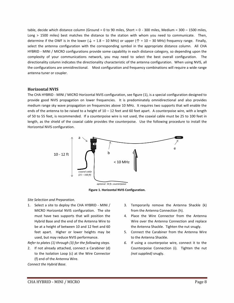
Horizontal NVIS The CHA HYBRID - MINI / MICRO Horizontal NVIS configuration, see figure (1), is a special configuration designed to
provide good NVIS propagation on lower frequencies. It is predominately omnidirectional and also provides
medium range sky wave propagation on frequencies above 10 MHz. It requires two supports that will enable the
ends of the antenna to be raised to a height of 10 – 12 feet and 60 feet apart. A counterpoise wire, with a length
of 50 to 55 feet, is recommended. If a counterpoise wire is not used, the coaxial cable must be 25 to 100 feet in
length, as the shield of the coaxial cable provides the counterpoise. Use the following procedure to install the
Horizontal NVIS configuration.
Figure 1. Horizontal NVIS Configuration.
Site Selection and Preparation.
1. Select a site to deploy the CHA HYBRID - MINI /
MICRO Horizontal NVIS configuration. The site
must have two supports that will position the
Hybrid Base and the end of the Antenna Wire to
be at a height of between 10 and 12 feet and 60
feet apart. Higher or lower heights may be
used, but may reduce NVIS performance.
Refer to plates (1) through (3) for the following steps.
2. If not already attached, connect a Carabiner (d)
to the Isolation Loop (c) at the Wire Connector
(f) end of the Antenna Wire.
Connect the Hybrid Base.
3. Temporarily remove the Antenna Shackle (k)
from the Antenna Connection (h).
4. Place the Wire Connector from the Antenna
Wire over the Antenna Connection and replace
the Antenna Shackle. Tighten the nut snugly.
5. Connect the Carabiner from the Antenna Wire
to the Antenna Shackle.
6. If using a counterpoise wire, connect it to the
Counterpoise Connection (i). Tighten the nut
(not supplied) snugly.
CHA HYBRID - MINI / MICRO Page 9
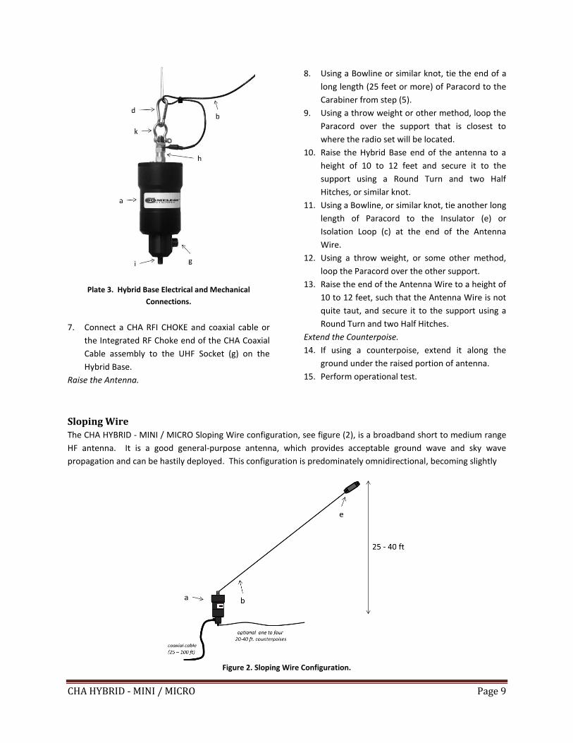
Plate 3. Hybrid Base Electrical and Mechanical
Connections.
7. Connect a CHA RFI CHOKE and coaxial cable or
the Integrated RF Choke end of the CHA Coaxial
Cable assembly to the UHF Socket (g) on the
Hybrid Base.
Raise the Antenna.
8. Using a Bowline or similar knot, tie the end of a
long length (25 feet or more) of Paracord to the
Carabiner from step (5).
9. Using a throw weight or other method, loop the
Paracord over the support that is closest to
where the radio set will be located.
10. Raise the Hybrid Base end of the antenna to a
height of 10 to 12 feet and secure it to the
support using a Round Turn and two Half
Hitches, or similar knot.
11. Using a Bowline, or similar knot, tie another long
length of Paracord to the Insulator (e) or
Isolation Loop (c) at the end of the Antenna
Wire.
12. Using a throw weight, or some other method,
loop the Paracord over the other support.
13. Raise the end of the Antenna Wire to a height of
10 to 12 feet, such that the Antenna Wire is not
quite taut, and secure it to the support using a
Round Turn and two Half Hitches.
Extend the Counterpoise.
14. If using a counterpoise, extend it along the
ground under the raised portion of antenna.
15. Perform operational test.
Sloping Wire The CHA HYBRID - MINI / MICRO Sloping Wire configuration, see figure (2), is a broadband short to medium range
HF antenna. It is a good general-purpose antenna, which provides acceptable ground wave and sky wave
propagation and can be hastily deployed. This configuration is predominately omnidirectional, becoming slightly
Figure 2. Sloping Wire Configuration.
CHA HYBRID - MINI / MICRO Page 10
unidirectional towards the end of the antenna wire as the frequency increases. The Sloping Wire requires one
support and should be mounted at a height of 25 to 40 feet for best performance. A counterpoise wire, with a
length of 20 to 40 feet, is recommended. If a counterpoise is not used, the coaxial cable must be 25 to 100 feet in
length, as the shield of the coaxial cable provides the counterpoise. The “Half Sloper” is an alternate version of this
configuration, where the antenna is attached to a metal tower and the antenna is fed from the top.
Site Selection and Preparation.
1. Select a site to deploy the CHA HYBRID - MINI /
MICRO Sloping Wire configuration. The site
must have a support that will position the end
of the Antenna Wire at a height of 25 to 40 feet.
If the right support is unavailable, any
convenient object, such as a fence post or the
top of a vehicle, may be used as a field
expedient support with reduced performance.
Refer to plates (1) through (3) for the following steps.
2. If not already attached, connect a Carabiner (d)
to the Isolation Loop (c) at the Wire Connector
(f) end of the Antenna Wire.
Connect the Hybrid Base. .
3. Temporarily remove the Antenna Shackle (k)
from the Antenna Connection (h).
4. Place the Wire Connector from the Antenna
Wire over the Antenna Connection and replace
the Antenna Shackle. Tighten the nut snugly.
5. Connect the Carabiner from the Antenna Wire
to the Antenna Shackle.
6. If using a counterpoise wire, connect it to the
Counterpoise Connection (i). Tighten the nut
(not supplied) snugly.
7. Connect a CHA RFI CHOKE and coaxial cable or
the Integrated RF Choke end of the CHA Coaxial
Cable assembly to the UHF Socket (g) on the
Hybrid Base.
Raise the Antenna.
8. Using a Bowline, or similar knot, tie a long
length (50 feet or more) of Paracord to the
Insulator (e) or Isolation Loop at the end of the
Antenna Wire.
9. Using a throw weight or some other method,
loop the Paracord over the support.
10. Raise the end of the Antenna Wire to the
desired height, and secure it to the support
using a Round Turn and two Half Hitches, or
similar knot.
11. Using a Bowline or similar knot, tie the end of a
short length (around 4 feet) of Paracord to the
Carabiner.
12. Fully extend the Antenna Wire so that it is not
quite taut,
13. Drive a Stake into the ground around two feet
beyond the end of the Antenna Wire and tie the
Paracord from the Hybrid Base to the Stake
using two Half Hitches, or similar knot.
Extend the Counterpoise.
14. If using a counterpoise wire, extend it along the
ground in any convenient direction.
15. Perform operational test.
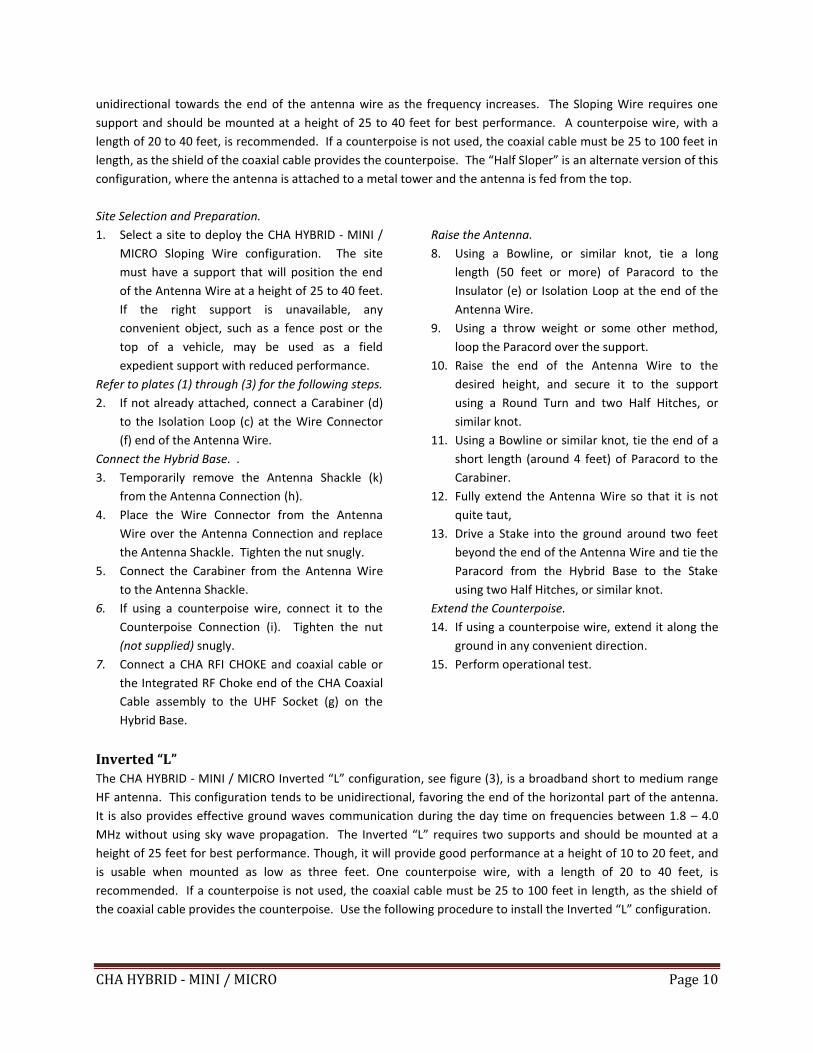
Inverted “L”
The CHA HYBRID - MINI / MICRO Inverted “L” configuration, see figure (3), is a broadband short to medium range
HF antenna. This configuration tends to be unidirectional, favoring the end of the horizontal part of the antenna.
It is also provides effective ground waves communication during the day time on frequencies between 1.8 – 4.0
MHz without using sky wave propagation. The Inverted “L” requires two supports and should be mounted at a
height of 25 feet for best performance. Though, it will provide good performance at a height of 10 to 20 feet, and
is usable when mounted as low as three feet. One counterpoise wire, with a length of 20 to 40 feet, is
recommended. If a counterpoise is not used, the coaxial cable must be 25 to 100 feet in length, as the shield of
the coaxial cable provides the counterpoise. Use the following procedure to install the Inverted “L” configuration.
CHA HYBRID - MINI / MICRO Page 11
Figure 3. Inverted “L” Configuration.
Site Selection and Preparation.
1. Select a site to deploy the CHA HYBRID - MINI /
MICRO Inverted “L” configuration. The site
must have two supports that will position the
corner of the “L” and the end of the Antenna
Wire at a height of about 25 feet. If the right
supports are unavailable, any convenient
objects, such as fence posts or the tops of
vehicles, may be used as a field expedient
supports with reduced performance.
Refer to plates (1) through (3) for the following steps.
2. If not already attached, connect a Carabiner (d)
to the Isolation Loop (c) at the Wire Connector
(f) end of the Antenna Wire (b).
Connect the Hybrid Base.
3. Temporarily remove the Antenna Shackle (k)
from the Antenna Connection (h).
4. Place the Wire Connector from the Antenna
Wire over the Antenna Connection and replace
the Antenna Shackle. Tighten the nut snugly.
5. Connect the Carabiner from the Antenna Wire
to the Antenna Shackle.
6. If using a counterpoise wire, connect it to the
Counterpoise Connection (i). Tighten the nut
(not supplied) snugly.
7. Connect a CHA RFI CHOKE and coaxial cable or
the Integrated RF Choke end of the CHA Coaxial
Cable assembly to the UHF Socket (g) on the
Hybrid Base.
Raise the Antenna.
8. Using a Bowline or similar knot, tie the end of a
short length (around 4 feet) of Paracord to the
Carabiner.
9. Drive a Stake into the ground near the location
closest to the radio set and tie the Paracord
from the Hybrid Base to the Stake using two Half
Hitches, or similar knot.
10. Using a Fisherman’s Hitch or similar knot, attach
a long length (50 feet or more) to the Antenna
Wire around 25 feet from the Hybrid Base (a).
This will form the corner of the “L”
11. Using a throw weight or some other method,
loop the Paracord over the support closest to
the radio set.
12. Using a Bowline or similar knot, tie a long length
of Paracord to the Insulator (e) or Isolation Loop
at the end of the Antenna Wire.
13. Using a throw weight or some other method,
loop the Paracord over the other support.
14. Pull the Paracord at the radio set end until the
Antenna Wire is at the desired height and
secure it to the support using a Round Turn and
two Half Hitches, or similar knot.
15. Pull the Paracord at the end of the Antenna
Wire, such that the Antenna Wire is not quite
taut, and secure it to the support using a Round
Turn and two Half Hitches, or similar knot.
CHA HYBRID - MINI / MICRO Page 12
Extend the Counterpoise.
16. If using a counterpoise wire, extend it along the
ground under the antenna.
17. Perform operational test.
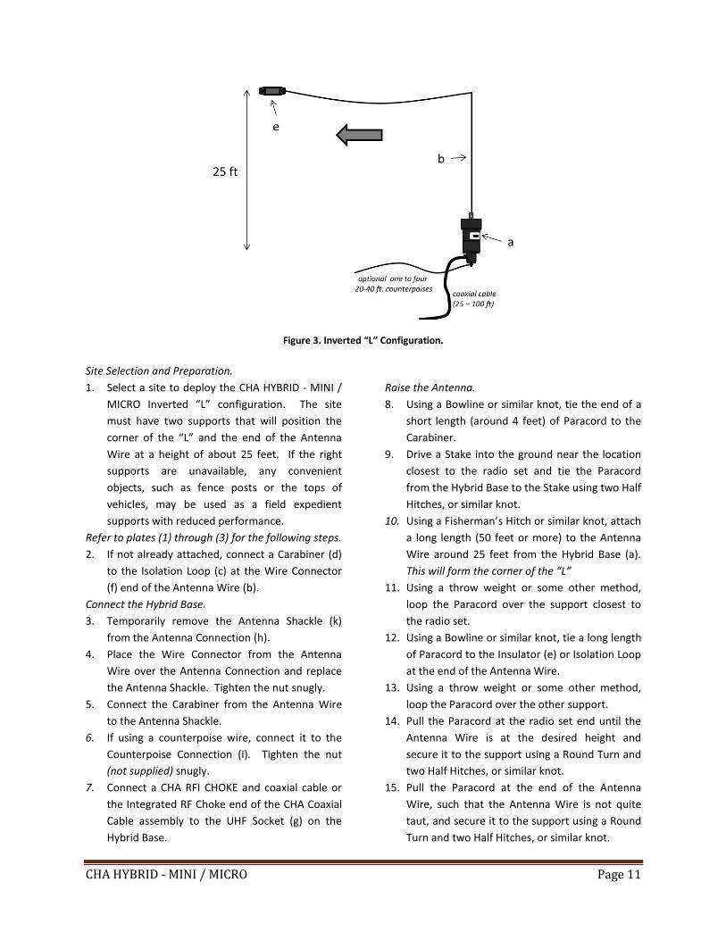
Manpack Vertical The CHA HYBRID - MINI / MICRO and CHA MIL WHIP Manpack Vertical configuration, see figure (4), is a broadband
short range HF/VHF-LO antenna. This configuration, which is especially designed to be manpackable, is
omnidirectional and provides ground wave communication on frequencies between 1.8 – 54.0 MHz without using
sky wave propagation. Performance is limited below 3.5 MHz, but very good above 24 MHz. A single 25 foot
counterpoise “tail wire” will provide a good compromise between portability and performance or you can use the
supplied 60 foot antenna wire as the counterpoise. An antenna tuner or coupler is required on most frequencies.
Figure 4. Manpack Vertical.
Site Selection and Preparation
1. Select a site to deploy the CHA HYBRID - MINI /
MICRO Manpack Vertical configuration. Best
ground wave communication occurs when the
radio set is located in a clear area and the whip
antenna is vertical.
Refer to plates (1) and (3) for the following steps.
2. If attached, remove the Antenna Shackle (k)
from the Hybrid Base (a) by loosening the nut on
the Antenna Shackle and then unscrewing the
Antenna Shackle from the Antenna Connector
(h). Store in secure place.
Connect the Hybrid Base. .
3. Attach a counterpoise wire to the Hybrid Base
by placing the counterpoise wire terminal lug
over the Counterpoise Connection (i) and
tightening the nut (not supplied) until snug.
4. Connect a CHA RFI CHOKE and coaxial cable or
the Integrated RF Choke end of the CHA Coaxial
Cable assembly to the UHF Socket (g) on the
Hybrid Base.
Raise the Antenna.
5. Extend the CHA MIL WHIP by unfolding the
sections of the whip, starting with the section
above the bottom section, and ensure each
section is fully seated onto section below until
the whip is fully extended.
6. Connect the CHA MIL WHIP to the Hybrid Base
by carefully screwing the 3/8” base stud into the
Antenna Connection (h) until finger tight.
CHA HYBRID - MINI / MICRO Page 13
Extend the Counterpoise
7. Extend the counterpoise wire along the ground
in any convenient direction.
8. Perform operational test.
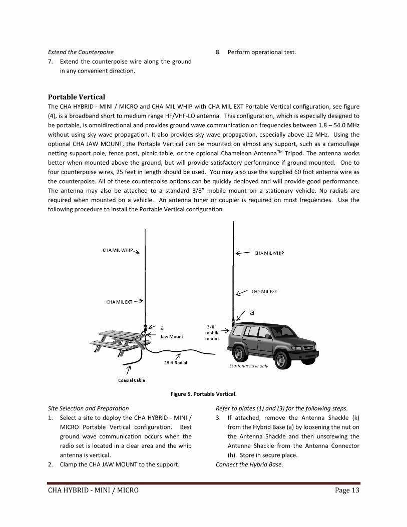
Portable Vertical
The CHA HYBRID - MINI / MICRO and CHA MIL WHIP with CHA MIL EXT Portable Vertical configuration, see figure
(4), is a broadband short to medium range HF/VHF-LO antenna. This configuration, which is especially designed to
be portable, is omnidirectional and provides ground wave communication on frequencies between 1.8 – 54.0 MHz
without using sky wave propagation. It also provides sky wave propagation, especially above 12 MHz. Using the
optional CHA JAW MOUNT, the Portable Vertical can be mounted on almost any support, such as a camouflage
netting support pole, fence post, picnic table, or the optional Chameleon AntennaTM Tripod. The antenna works
better when mounted above the ground, but will provide satisfactory performance if ground mounted. One to
four counterpoise wires, 25 feet in length should be used. You may also use the supplied 60 foot antenna wire as
the counterpoise. All of these counterpoise options can be quickly deployed and will provide good performance.
The antenna may also be attached to a standard 3/8” mobile mount on a stationary vehicle. No radials are
required when mounted on a vehicle. An antenna tuner or coupler is required on most frequencies. Use the
following procedure to install the Portable Vertical configuration.
Figure 5. Portable Vertical.
Site Selection and Preparation
1. Select a site to deploy the CHA HYBRID - MINI /
MICRO Portable Vertical configuration. Best
ground wave communication occurs when the
radio set is located in a clear area and the whip
antenna is vertical.
2. Clamp the CHA JAW MOUNT to the support.
Refer to plates (1) and (3) for the following steps.
3. If attached, remove the Antenna Shackle (k)
from the Hybrid Base (a) by loosening the nut on
the Antenna Shackle and then unscrewing the
Antenna Shackle from the Antenna Connector
(h). Store in secure place.
Connect the Hybrid Base.
CHA HYBRID - MINI / MICRO Page 14
4. If used, place the terminal lugs of the
counterpoise wires over the Counterpoise
Connection (i) on the Hybrid Base. You can use
either the Antenna Wire (b) or optional
Counterpoise Kit.
5. Screw the Hybrid Base Counterpoise Connection
into the 3/8” antenna mount of the Jaw Mount
until finger tight.
6. Connect a CHA RFI CHOKE and coaxial cable or
the Integrated RF Choke end of the CHA Coaxial
Cable assembly to the UHF Socket (g) on the
Hybrid Base.
Raise the Antenna
7. Extend the CHA MIL EXT by unfolding the middle
section of the extension, fully seating it onto the
bottom section, then unfolding the top section
and fully seating onto the middle section.
8. Connect the CHA MIL EXT to the Hybrid Base by
carefully screwing it into the Antenna
Connection until finger tight.
9. Extend the CHA MIL WHIP by unfolding the
sections of the whip, starting with the section
above the bottom section, and ensure each
section is fully seated onto section below until
the whip is fully extended.
10. Connect the CHA MIL WHIP to the CHA MIL EXT
by carefully screwing the 3/8” base stud into the
top section until finger tight.
Extend the Counterpoise
11. Extend the counterpoise wire along the ground
in any convenient direction. The end of the
counterpoise wire can be secured to the ground
with a tent stake.
12. Perform operational test.
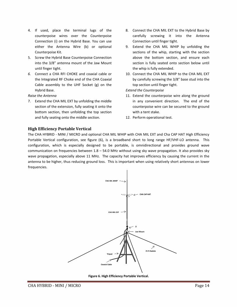
High Efficiency Portable Vertical
The CHA HYBRID - MINI / MICRO and optional CHA MIL WHIP with CHA MIL EXT and Cha CAP HAT High Efficiency
Portable Vertical configuration, see figure (6), is a broadband short to long range HF/VHF-LO antenna. This
configuration, which is especially designed to be portable, is omnidirectional and provides ground wave
communication on frequencies between 1.8 – 54.0 MHz without using sky wave propagation. It also provides sky
wave propagation, especially above 11 MHz. The capacity hat improves efficiency by causing the current in the
antenna to be higher, thus reducing ground loss. This is important when using relatively short antennas on lower
frequencies.
Figure 6. High Efficiency Portable Vertical.
CHA HYBRID - MINI / MICRO Page 15
Using the optional Jaw Mount, the Portable Vertical can be mounted on almost any support, such as a camouflage
netting support pole, fence post, picnic table, or the optional Chameleon AntennaTM Tripod. The antenna works
better when mounted above the ground, but will provide satisfactory performance if ground mounted. One to
four counterpoise wires, 25 feet in length should be used. They can be quickly deployed and will provide good
performance. The antenna may also be attached to a standard 3/8” mobile mount on a stationary vehicle. No
radials are required when mounted on a vehicle. An antenna tuner or coupler is required on most frequencies.
Install the Capacity Hat
1. Follow the procedure for the Portable Vertical configuration, except add the following step between steps (9)
and (10).
2. Install the CHA CAP HAT between the CHA MIL EXT and CHA MIL WHIP by screwing the 3/8” threaded fitting of
the CHA CAP HAT into the top section of the CHA MIL EXT and the CHA MIL WHIP 3/8” base stud into the hub
of CHA CAP HAT.
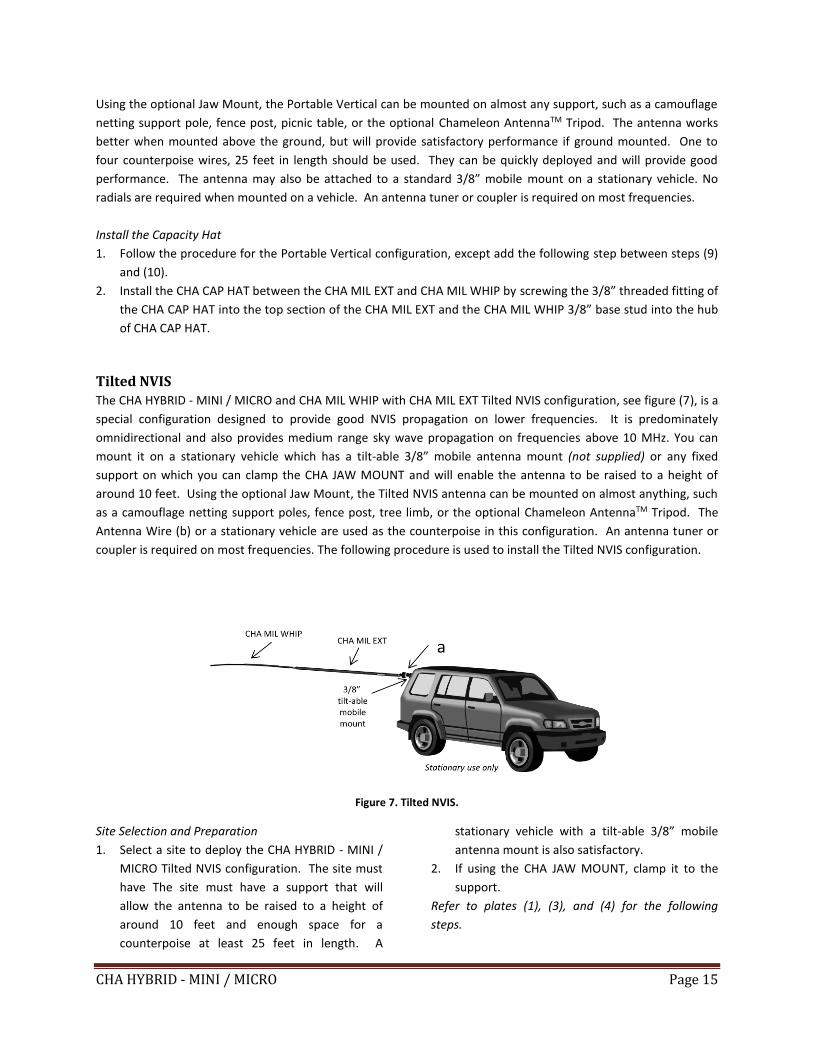
Tilted NVIS The CHA HYBRID - MINI / MICRO and CHA MIL WHIP with CHA MIL EXT Tilted NVIS configuration, see figure (7), is a
special configuration designed to provide good NVIS propagation on lower frequencies. It is predominately
omnidirectional and also provides medium range sky wave propagation on frequencies above 10 MHz. You can
mount it on a stationary vehicle which has a tilt-able 3/8” mobile antenna mount (not supplied) or any fixed
support on which you can clamp the CHA JAW MOUNT and will enable the antenna to be raised to a height of
around 10 feet. Using the optional Jaw Mount, the Tilted NVIS antenna can be mounted on almost anything, such
as a camouflage netting support poles, fence post, tree limb, or the optional Chameleon AntennaTM Tripod. The
Antenna Wire (b) or a stationary vehicle are used as the counterpoise in this configuration. An antenna tuner or
coupler is required on most frequencies. The following procedure is used to install the Tilted NVIS configuration.
Figure 7. Tilted NVIS.
Site Selection and Preparation
1. Select a site to deploy the CHA HYBRID - MINI /
MICRO Tilted NVIS configuration. The site must
have The site must have a support that will
allow the antenna to be raised to a height of
around 10 feet and enough space for a
counterpoise at least 25 feet in length. A
stationary vehicle with a tilt-able 3/8” mobile
antenna mount is also satisfactory.
2. If using the CHA JAW MOUNT, clamp it to the
support.
Refer to plates (1), (3), and (4) for the following
steps.
CHA HYBRID - MINI / MICRO Page 16
3. If attached, remove the Antenna Shackle (k)
from the Hybrid Base (a) by loosening the nut on
the Antenna Shackle and then unscrewing the
Antenna Shackle from the Antenna Connector
(h). Store in a secure place.
Plate 4. Dipole Jaw Mount.
Connect the Hybrid Base.
4. If using a counterpoise wire, place the terminal
lug of the Antenna Wire over the Counterpoise
Connection (i) on the Hybrid Base.
5. Screw the Hybrid Base Counterpoise Connection
into one of the 3/8” antenna mount on the
Dipole Jaw Mount until finger tight.
6. Connect a CHA RFI CHOKE and coaxial cable or
the Integrated RF Choke end of the CHA Coaxial
Cable assembly to the UHF Socket (g) on the
Hybrid Base. You will not be using the UHF
Socket (SO-239) on the 3/8” antenna mount.
Raise the Antenna
7. Extend the CHA MIL EXT by unfolding the middle
section of the extension, fully seating it onto the
bottom section, then unfolding the top section
and fully seating onto the middle section.
8. Connect the CHA MIL EXT to the Hybrid Base by
carefully screwing it into the Antenna
Connection until finger tight.
9. Extend the CHA MIL WHIP by unfolding the
sections of the whip, starting with the section
above the bottom section, and ensure each
section is fully seated onto section below until
the whip is fully extended.
10. Connect the CHA MIL WHIP to the CHA MIL EXT
by carefully screwing it into the top section until
finger tight.
Extend the Counterpoise.
11. If not using a vehicle as the counterpoise,
extend the counterpoise wire along the ground
in any convenient direction. The end of the
counterpoise wire can be secured to the ground
with a tent stake.
12. Perform operational test.
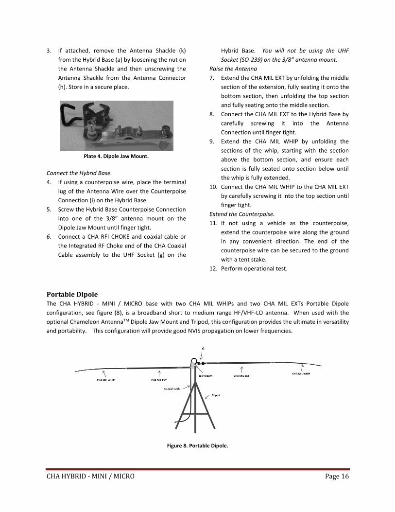
Portable Dipole The CHA HYBRID - MINI / MICRO base with two CHA MIL WHIPs and two CHA MIL EXTs Portable Dipole
configuration, see figure (8), is a broadband short to medium range HF/VHF-LO antenna. When used with the
optional Chameleon AntennaTM Dipole Jaw Mount and Tripod, this configuration provides the ultimate in versatility
and portability. This configuration will provide good NVIS propagation on lower frequencies.
Figure 8. Portable Dipole.
CHA HYBRID - MINI / MICRO Page 17
It is predominately omnidirectional and also provides medium range sky wave propagation on frequencies above
10 MHz. An antenna tuner or coupler is required for most frequencies.
Site Selection and Preparation
1. Select a site to deploy the CHA HYBRID - MINI /
MICRO Portable Dipole configuration. The best
location would be a clear and reasonably level
area.
2. Clamp the Dipole Jaw Mount to the Tripod.
Refer to plates (1), (3) and (4) for the following steps.
3. If attached, remove the Antenna Shackle (k)
from the Hybrid Base (a) by loosening the nut on
the Antenna Shackle and then unscrewing the
Antenna Shackle from the Antenna Connector
(h). Store in secure place.
Connect the Hybrid Base.
4. Screw the Hybrid Base Counterpoise Connection
(i) into the 3/8” antenna mount on the Jaw
Mount until finger tight.
5. Connect a CHA RFI CHOKE and coaxial cable or
the Integrated RF Choke end of the CHA Coaxial
Cable assembly to the UHF Socket (g) on the
Hybrid Base. You will not be using the UHF
Socket (SO-239) on the Jaw Mount.
Raise the Antenna.
6. Extend the CHA MIL EXT by unfolding the middle
section of the extension, fully seating it onto the
bottom section, then unfolding the top section
and fully seating onto the middle section.
7. Connect the CHA MIL EXT to the Hybrid Base by
carefully screwing it into the Antenna
Connection until finger tight.
8. Extend the CHA MIL WHIP by unfolding the
sections of the whip, starting with the section
above the bottom section, and ensure each
section is fully seated onto section below until
the whip is fully extended.
9. Connect the CHA MIL WHIP to the CHA MIL EXT
by carefully screwing it into the top section until
finger tight.
Extend the Counterpoise
10. Extend the CHA MIL EXT by unfolding the middle
section of the extension, fully seating it onto the
bottom section, then unfolding the top section
and fully seating onto the middle section.
11. Connect the CHA MIL EXT to the Hybrid Base by
carefully screwing it into the other 3/8” antenna
mount on the Jaw Mount until finger tight.
12. Extend the CHA MIL WHIP by unfolding the
sections of the whip, starting with the section
above the bottom section, and ensure each
section is fully seated onto section below until
the whip is fully extended.
13. Connect the CHA MIL WHIP to the CHA MIL EXT
by carefully screwing it into the top section until
finger tight.
14. Perform operational test.
Recovery Procedure To recover the CHA HYBRID - MINI / MICRO, perform the following steps:
1. Disconnect the Coaxial Cable from the radio set.
2. Lower the antenna to the ground.
3. Disconnect the Coaxial Cable from the Hybrid Base (a).
4. Carefully roll (do not twist) the Coaxial Cable.
5. Untie the Paracord from the Hybrid Base and Antenna Wire (b), as applicable and wind on line winder.
6. Disconnect the antenna from the Hybrid Base.
7. HYBRID MINI: Roll (do not kink) the Antenna Wire and secure with a short length of Paracord.
8. HYBRID MICRO: Wind the Antenna Wire onto the Line Winder (e) and secure with attached shock cord.
9. CHA MIL EXT: Starting at the bottom, pull the section apart from the section above and fold the section above
over the section below. Repeat until all sections are apart. Secure the sections together with provided sticky
strap.
CHA HYBRID - MINI / MICRO Page 18
10. CHA MIL WHIP: Starting at the bottom, pull the section apart from the section above and fold the section
above over the section below. Repeat until all sections are apart. Secure the sections together with provided
sticky strap.
11. CHA CAP HAT: Store the assembled capacity hat where it will not get bent when not in use. We recommend
that you do not disassemble the CHA CAP HAT.
12. Pull the Stakes from the ground, if used.
13. Remove dirt from antenna components and inspect them for signs of wear.
14. Store components together.
Troubleshooting 1. If using the Antenna Wire (b), ensure Wire Connector is securely connected.
2. Inspect Antenna Wire or Whip for breakage or signs of strain.
3. Ensure UHF Plugs are securely tightened.
4. Inspect Coaxial Cable assembly for cuts in insulation or exposed shielding. Replace if damaged.
5. If still not operational, connect a Standing Wave Ratio (SWR) Power Meter and check SWR.
6. If SWR is greater than 10:1, check antenna tuner or coupler using the technical manual or manufacturer’s
procedure. Be sure to check the Coaxial Patch Cable that connects the radio set to the antenna tuner or
coupler.
7. If still not operational, replace Coaxial Cable assembly. Most problems with antenna systems are caused by
the coaxial cables and connectors.
8. Connect a Multi-Meter to the Antenna Wire to check continuity. Replace assemblies that do not pass a
continuity check.
9. If still not operational, replace Hybrid Base (a).
Specifications • Frequency: (all configurations require a wide range antenna tuner or coupler)
o CHA HYBRID MINI / MICRO: 1.8 MHz through 54 MHz continuous (including all Amateur Radio
Service bands 160m to 6m).
o CHA MIL WHIP: 24 – 54 MHz (whip only), 1.8 – 54 MHz (with CHA HYBRID MINI / MICRO. Limited
performance below 3.5 MHz.)
o CHA MIL WHIP with CHA MIL EXT: 12 – 54 MHz (whip and extension only), 1.8 – 54 MHz (with
CHA HYBRID MINI / MICRO.)
• Power:
o CHA HYBRID MINI : 250 W continuous duty cycle (CW, AM, FM, RTTY), 800 W intermittent duty
cycle (SSB and SSB-based digital modes)
o CHA HYBRID MICRO: 50 W continuous duty cycle (CW, AM, FM, RTTY), 100 W intermittent duty
cycle (SSB and SSB-based digital modes)
• RF Connection: UHF Plug (PL-259)
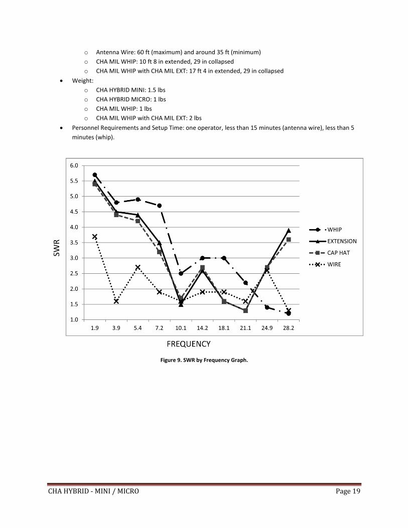
• SWR: Subject to frequency and configuration, but within limits of most wide range antenna tuners or
couplers. Figure (9) shows a graph of SWR by frequency for a typical deployment.
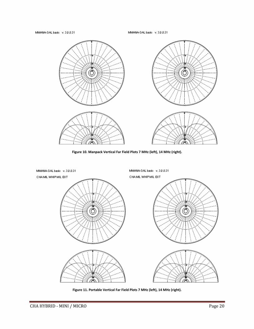
• Hybrid Configuration Far Field Plots are shown in figures (10) through (16).
• Length:
CHA HYBRID - MINI / MICRO Page 19
o Antenna Wire: 60 ft (maximum) and around 35 ft (minimum)
o CHA MIL WHIP: 10 ft 8 in extended, 29 in collapsed
o CHA MIL WHIP with CHA MIL EXT: 17 ft 4 in extended, 29 in collapsed
• Weight:
o CHA HYBRID MINI: 1.5 lbs
o CHA HYBRID MICRO: 1 lbs
o CHA MIL WHIP: 1 lbs
o CHA MIL WHIP with CHA MIL EXT: 2 lbs
• Personnel Requirements and Setup Time: one operator, less than 15 minutes (antenna wire), less than 5
minutes (whip).
Figure 9. SWR by Frequency Graph.
CHA HYBRID - MINI / MICRO Page 20
Figure 10. Manpack Vertical Far Field Plots 7 MHz (left), 14 MHz (right).
Figure 11. Portable Vertical Far Field Plots 7 MHz (left), 14 MHz (right).
CHA HYBRID - MINI / MICRO Page 21
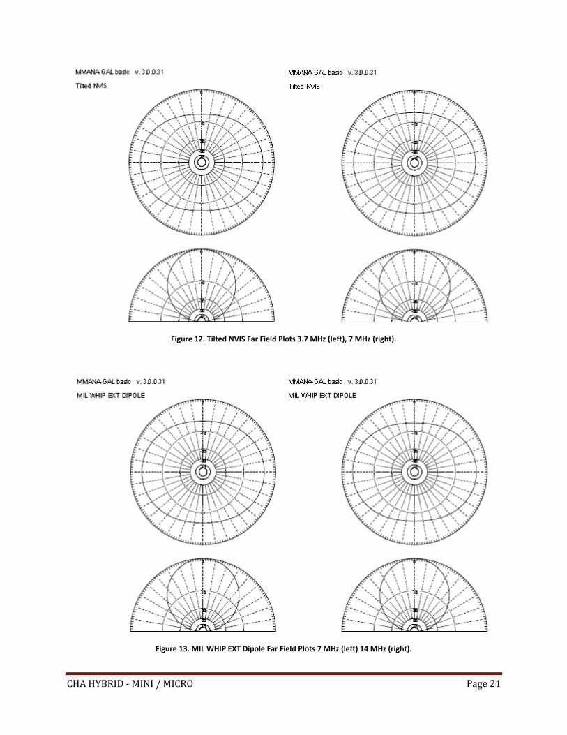
Figure 12. Tilted NVIS Far Field Plots 3.7 MHz (left), 7 MHz (right).
Figure 13. MIL WHIP EXT Dipole Far Field Plots 7 MHz (left) 14 MHz (right).
CHA HYBRID - MINI / MICRO Page 22
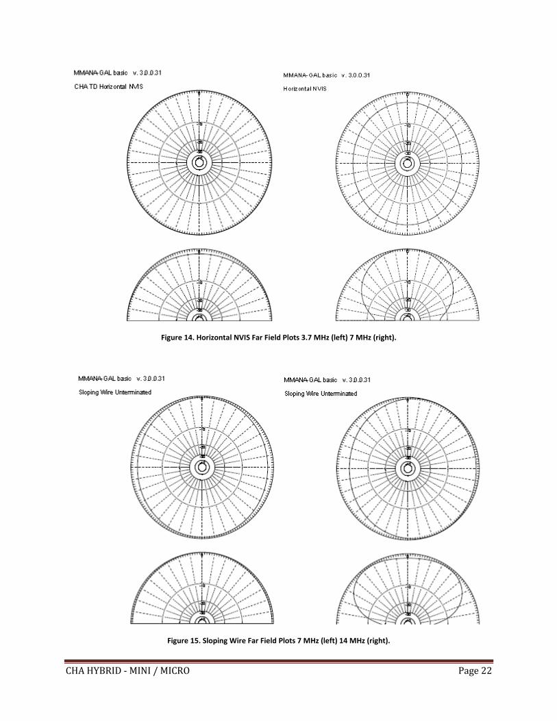
Figure 14. Horizontal NVIS Far Field Plots 3.7 MHz (left) 7 MHz (right).
Figure 15. Sloping Wire Far Field Plots 7 MHz (left) 14 MHz (right).
CHA HYBRID - MINI / MICRO Page 23
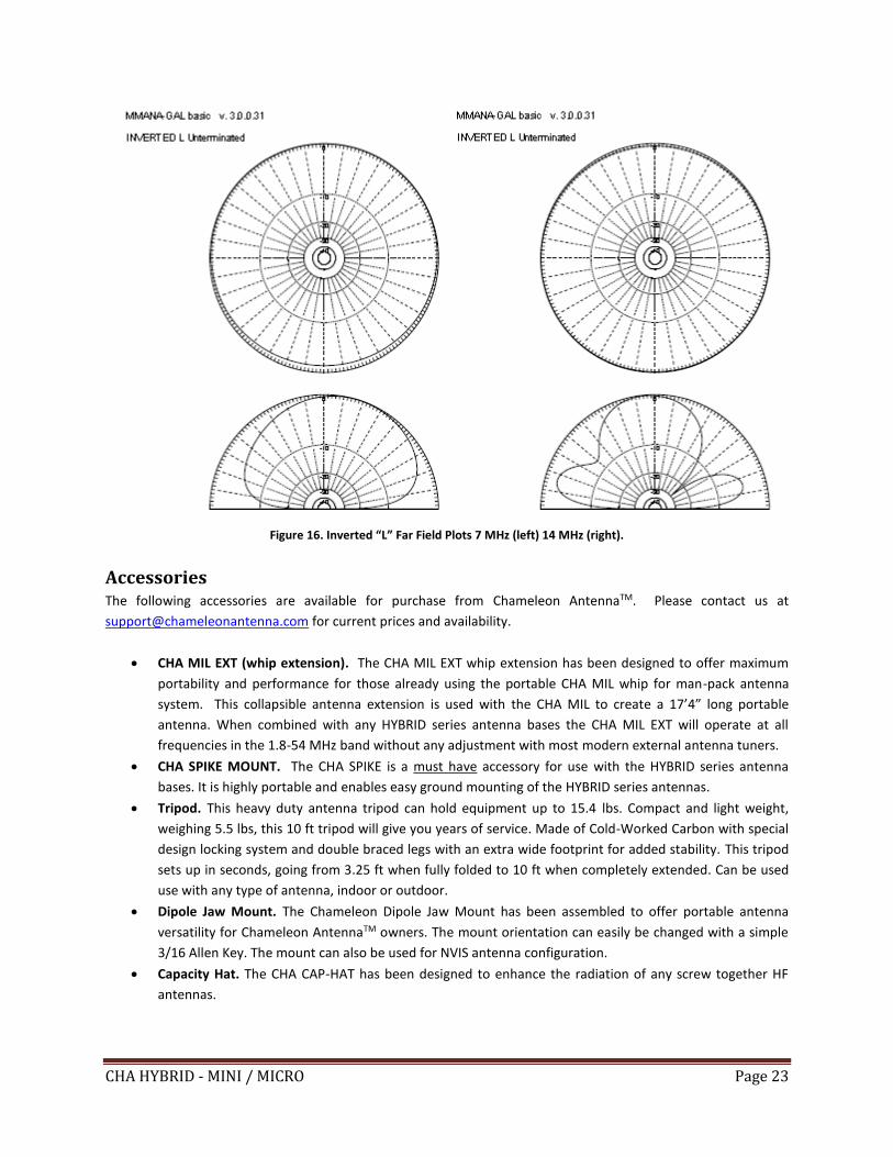
Figure 16. Inverted “L” Far Field Plots 7 MHz (left) 14 MHz (right).
Accessories The following accessories are available for purchase from Chameleon AntennaTM. Please contact us at
[email protected] for current prices and availability.
• CHA MIL EXT (whip extension). The CHA MIL EXT whip extension has been designed to offer maximum
portability and performance for those already using the portable CHA MIL whip for man-pack antenna
system. This collapsible antenna extension is used with the CHA MIL to create a 17’4” long portable
antenna. When combined with any HYBRID series antenna bases the CHA MIL EXT will operate at all
frequencies in the 1.8-54 MHz band without any adjustment with most modern external antenna tuners.
• CHA SPIKE MOUNT. The CHA SPIKE is a must have accessory for use with the HYBRID series antenna
bases. It is highly portable and enables easy ground mounting of the HYBRID series antennas.
• Tripod. This heavy duty antenna tripod can hold equipment up to 15.4 lbs. Compact and light weight,
weighing 5.5 lbs, this 10 ft tripod will give you years of service. Made of Cold-Worked Carbon with special
design locking system and double braced legs with an extra wide footprint for added stability. This tripod
sets up in seconds, going from 3.25 ft when fully folded to 10 ft when completely extended. Can be used
use with any type of antenna, indoor or outdoor.
• Dipole Jaw Mount. The Chameleon Dipole Jaw Mount has been assembled to offer portable antenna
versatility for Chameleon AntennaTM owners. The mount orientation can easily be changed with a simple
3/16 Allen Key. The mount can also be used for NVIS antenna configuration.
• Capacity Hat. The CHA CAP-HAT has been designed to enhance the radiation of any screw together HF
antennas.
CHA HYBRID - MINI / MICRO Page 24
• Counterpoise Kit. The Counterpoise Kit is ideal for portable antenna deployment. The system will create
the ground-plane needed to any vertical antennas and will also play the role of guy wires. It contains four
25 foot wire radials secured around plastic wire winders and four steel tent stakes.
• 50’ Paracord and Line Winder Assembly. One assembly is recommended to enable installation of the
CHA HYBRID - MINI / MICRO wire configurations.
• Coaxial Cable Assembly. 50 feet of RG-58 with integrated RFI Choke. Used to connect the CHA HYBRID -
MINI / MICRO to the radio set. This is a highly recommended accessory if you are not using a CHA RFI
CHOKE.
• RF Choke Assembly. The CHA RFI CHOKE will prevent, greatly reduces or totally eliminates the RFI carried
by the coax cable. It can be installed either at the antenna feed point or right behind the antenna tuner.
This accessory is highly recommended if you are not using the Chameleon AntennaTM Coaxial Cable
Assembly.
Recommended non-supplied accessories:
• The following hardware is needed to attach the counterpoise wires to the Hybrid Base, if not using the
Jaw Mount:
o One 3/8” x 24 (fine thread; not the common 3/8” x 16 course thread) stainless steel hex nut or
wing nut.
o One 3/8” stainless steel flat washer.
o One 3/8” stainless steel split washer.
• Wide range antenna tuner or coupler. Required for most configurations.
• Flashlight.
• Multi-tool.
• Throwing weight and string.
• Mallet.
• SWR Power Meter.
• Multi-Meter.
• Small canvas or nylon bag to store antenna components.
Chameleon AntennaTM Products The following products are available for purchase at Chameleon AntennaTM.
Go to http://chameleonantenna.com for ordering and more information.
CHA P-LOOP 2.0 - The CHA P-LOOP 2.0 was designed
with portability, ease of use simplicity, ruggedness
and high performance in mind. Unlike any other
similar antennas on the market, the CHA P-LOOP 2.0
is made with premium materials that are precisely
manufactured and assembled in the USA! This is an
exciting new product from Chameleon Antenna.
Easily deployable HF magnetic loop antennas, also
called small transmitting loops, have been routinely
used for many years in military, diplomatic, and
shipboard HF communication links, where robust
and reliable general coverage radio communication
is a necessity. Covers 7.0-29.7 MHz.
CHA F-LOOP 2.0 – The CHA F-LOOP 2.0 was designed
with portability, ease of use simplicity, ruggedness
and high performance in mind. Unlike any other
similar antennas on the market, the CHA F-LOOP 2.0
is made with premium materials that are precisely
manufactured and assembled in the USA! Easily
deployable HF magnetic loop antennas, also called
small transmitting loops, have been routinely used
CHA HYBRID - MINI / MICRO Page 25
for many years in military, diplomatic, and shipboard
HF communication links, where robust and reliable
general coverage radio communication is a
necessity. Covers 3.5-29.7 MHz.
CHA WINDOM 40 – The CHA WINDOM 40 Antenna is
designed for 40, 20, and 10 meters. Amateur Bands
from 60 through 10 meters can be operated using an
antenna tuner. Built with the portable operator in
mind, it is very light weight, easy to set up, and
comes with a military-style pouch.
CHA EMCOMM II - The CHA EMCOMM II Antenna
has been specially designed for backup emergency
HF system or permanent installation. The integral
broadband impedance matching network allows
broadband antenna tuning.
CHA SKYLOOP - The CHA SKYLOOP is a 250' full wave
loop antenna cut for 80M. With the help of an
antenna tuner, the CHA SKYLOOP will cover all the
bands between 80M and 6M.
CHA Hybrid Mini – Portable HF Antenna Base - The
CHA HYBRID-MINI Base is the portable version of the
regular HYBRID. The unit can be differentiated by the
color of the lid and the base connector, which is
black instead of gray. The HYBRID-MINI is also
smaller and about 50% lighter than the regular
HYBRID. An external antenna tuner is required to
provide a low VSWR. The connector provided with
the antenna is a SO-239 sealed. The entire unit is
also waterproof. The HYBRID-MINI will serve as
impedance transformer matching network and will
greatly reduce the VSWR at the load for the
following antennas: V1, V1L, V2L and MIL.
CHA V2L Mobile Antenna - The CHA V2L is a rugged
multiband HF antenna designed for smaller vehicles.
CHA VHF/UHF Magnetic Mount Mobile Antenna -
The CHA VHF/UHF is a simple but great dual band
antenna for 2M and 70CM.
CHA MIL Whip - The CHA MIL whip is a broadband
(28 to 54 MHz) monopole antenna designed for
portable or man-pack radios requiring compact but
rugged antenna systems. Its design has been
borrowed from similar antennas utilized by many
armies all over the world. The CHA MIL is very hardy,
sturdy and portable (being collapsible). Un-mounted
the entire antenna length is less than 29”. The 5
aluminum sections are hold together by a piece of
1/8th inch US GI MIL SPEC shock cord. The CHA MIL
Whip and a CHA HYBRID-MINI Base perfectly
complements the capability of the CHA HYBRID -
MINI / MICRO.
CHA MIL EXT Whip Extension - The CHA MIL EXT
whip has been designed to offer maximum
portability and performance for those already using
the portable CHA MIL whip for man-pack antenna
system. This collapsible antenna extension needs to
be used with the CHA MIL to create a 17’4” long
portable antenna. When combined with any HYBRID
series antenna bases the CHA MIL EXT will operate at
all frequencies in the 1.8-54 MHz band without any
adjustment with most modern external antenna
tuners.
CHA TD Tactical Dipole LITE - The CHA TD LITE
(Tactical Dipole LITE) is a HF broadband antenna
specially designed for portable HF communication
where rapid deployment and simplicity of operation
is essential but compactness is a primary
consideration. The antenna will operate at all
frequencies in the 1.8-54 MHz band without any
adjustment with most modern external antenna
tuners. No masts or guying are required.
CHA TD Tactical Dipole - The CHA TD (Tactical
Dipole) Antenna is a HF broadband antenna specially
designed for portable HF communication where
rapid deployment and simplicity of operation is
essential. The antenna will operate at all frequencies
in the 1.8-30 MHz band without any adjustment with
most modern internal antenna tuners. It is ideal for
use in conjunction with modern, digitally configured,
HF communication transceivers where features such
as ALE and frequency hopping require true
broadband capability. The antenna will work
successfully supported by trees, masts, the tops of
CHA HYBRID - MINI / MICRO Page 26
vehicles or any convenient object or structure. The
CHA TD can also be used without antenna tuner, as
the SWR will stay under 2.5:1 between 10M and
80M and under 2.75:1 on 160M.
CHA FT-817 BRACKETS 2.0 – CHA FT-817 Brackets
are built exclusively by the skilled machinists of
Chameleon AntennaTM. It is a military-style pair of
precision fabricated brackets and high quality
carrying strap for the popular Yaesu FT-817 series
portable QRP transceiver. The CHA FT-817 Brackets
will ruggedize and help protect your FT-817 from the
many hazards of field operations.
CHA MIL EXT Whip Extension - The CHA MIL EXT
whip has been designed to offer maximum
portability and performance for those already using
the portable CHA MIL whip for man-pack antenna
system. This collapsible antenna extension needs to
be used with the CHA MIL to create a 17’4” long
portable antenna. When combined with any HYBRID
series antenna bases the CHA MIL EXT will operate at
all frequencies in the 1.8-54 MHz band without any
adjustment with most modern external antenna
tuners.
CHA TD Tactical Dipole LITE - The CHA TD LITE
(Tactical Dipole LITE) is a HF broadband antenna
specially designed for portable HF communication
where rapid deployment and simplicity of operation
is essential but compactness is primordial. The
antenna will operate at all frequencies in the 1.8-54
MHz band without any adjustment with most
modern external antenna tuners. No masts or guying
are required.
CHA TD Tactical Dipole - The CHA TD (Tactical
Dipole) Antenna has been designed as an add-on for
the CHA HYBRID - MINI / MICRO. The CHA TD is a HF
broadband antenna specially designed for portable
HF communication where rapid deployment and
simplicity of operation is essential. The antenna will
operate at all frequencies in the 1.8-30 MHz band
without any adjustment with most modern internal
antenna tuners. It is ideal for use in conjunction with
modern, digitally configured, HF communication
transceivers where features such as ALE and
frequency hopping require true broadband
capability. No masts or guying are required. The
CHA TD can also be used without antenna tuner, as
the SWR will stay under 2.5:1 between 10M and
80M and under 2.75:1 on 160M.
References 1. Silver, H. Ward (editor), 2013, 2014 ARRL Handbook for Radio Communications, 91st Edition, American Radio
Relay League, Newington, CT.
2. 1987, Tactical Single-Channel Radio Communications Techniques (FM 24-18), Department of the Army,
Washington, DC.
3. Turkes, Gurkan, 1990, Tactical HF Field Expedient Antenna Performance Volume I Thesis, U.S. Naval Post
Graduate School, Monterey, CA.