hybrid structural control using magnetorheological dampers ... · hybrid structural control using...
TRANSCRIPT

Hybrid structural control using magnetorheological dampers for base isolated structures
This article has been downloaded from IOPscience. Please scroll down to see the full text article.
2009 Smart Mater. Struct. 18 055011
(http://iopscience.iop.org/0964-1726/18/5/055011)
Download details:
IP Address: 137.44.1.174
The article was downloaded on 09/08/2010 at 10:51
Please note that terms and conditions apply.
View the table of contents for this issue, or go to the journal homepage for more
Home Search Collections Journals About Contact us My IOPscience
IOP PUBLISHING SMART MATERIALS AND STRUCTURES
Smart Mater. Struct. 18 (2009) 055011 (16pp) doi:10.1088/0964-1726/18/5/055011
Hybrid structural control usingmagnetorheological dampers forbase isolated structuresSk Faruque Ali and Ananth Ramaswamy1
Department of Civil Engineering, Indian Institute of Science, Bangalore-560012, India
E-mail: [email protected] and [email protected]
Received 25 September 2008, in final form 26 January 2009Published 6 April 2009Online at stacks.iop.org/SMS/18/055011
AbstractIn this paper two nonlinear model based control algorithms have been developed to monitor themagnetorheological (MR) damper voltage. The main advantage of the proposed algorithms isthat it is possible to directly monitor the voltage required to control the structural vibrationconsidering the effect of the supplied and commanded voltage dynamics of the damper. Theefficiency of the proposed techniques has been shown and compared taking an example of abase isolated three-storey building under a set of seismic excitations. Comparison of theperformances with a fuzzy based intelligent control algorithm and a widely used clippedoptimal strategy has also been shown.
(Some figures in this article are in colour only in the electronic version)
1. Introduction
The destruction caused by seismic events over centuries acrossthe world have clearly demonstrated the importance and theurgency of mitigating the effect of such natural hazards onstructures. One of the biggest challenges structural engineersface today is finding more effective means for protectingstructures and their contents from the damaging effects ofdynamic hazards such as strong earthquakes. The idea of usingcontrol systems to dissipate, counteract, or isolate vibrationenergy has been identified as one promising approach in thisdirection (see [1]).
A control system can be classified as either passive,active, hybrid, or semi-active based on the level of energyrequired and the type of control devices employed. Amongthese systems, the semi-active approach has recently receivedconsiderable attention, because it offers significant adaptabilityof active systems without large power requirements and isas reliable as passive systems. Rapid-response, fail-safe,low power requirement, simple interfaces between electroniccontrols and mechanical systems are some characteristicsof magnetorheological (MR) devices that have attractedsignificant research interest for using them as semi-activecontrol devices in applications of vibration mitigation [1, 2].
1 Author to whom any correspondence should be addressed.
In particular, it has been found that MR dampers can bedesigned to be very effective vibration control actuators.In civil engineering, MR damper applications have mainlycentred around the structural vibration control under wind andearthquake excitations [2, 3]. The automotive industry hasbeen interested in developing applications of these materials,for example, for engine mounts, shock absorbers, clutches, andseat dampers [4].
Magnetorheological dampers are nonlinear devices dueto their inherent hysteretic damping characteristics. Theirnonlinear hysteretic characteristics are varied (monitored) bychanging the input voltage to the damper. The nonlinearhysteretic behaviour and voltage monitoring make the designof suitable control algorithms, that can provide a smoothchange in voltage, an interesting and challenging task. Theforce predicted by the available control algorithms is mappedto equivalent voltage and then fed into the damper. This inversemapping of force to voltage makes the choice and developmentof control algorithms more complicated. Available semi-activecontrol algorithms in the literature use an ‘on–off’ or ‘bang–bang’ strategy for MR applications. The ‘on–off’ nature ofthese algorithms neither provides a smooth change in MRdamper voltage input nor does it consider all possible voltagevalues within its full range [5].
A wide range of theoretical and experimental studies hasbeen performed to assess the efficacy of MR dampers as
0964-1726/09/055011+16$30.00 © 2009 IOP Publishing Ltd Printed in the UK1
Smart Mater. Struct. 18 (2009) 055011 Sk F Ali and A Ramaswamy
semi-active devices [5, 6]. In one of the first examinations,Karnopp et al [4] proposed a ‘skyhook’ damper controlalgorithm for a vehicle suspension system and demonstratedthat this system offers improved performance over a passivesystem when applied to a single-degree-of-freedom (SDOF)system. Thereafter, bang–bang [7] and Lyapunov functionbased approaches have been studied and reported [8, 9]. Dykeet al [2] proposed a clipped optimal control algorithm basedon acceleration feedback for the MR damper. In this approach,a linear optimal controller, combined with a force feedbackloop, was designed to adjust the command voltage of the MRdamper. The command signal was set at either zero or themaximum level depending on how the damper force comparedwith the target optimal control force. The target optimalcontrol can be obtained from the H2/LQG (linear quadraticGaussian) [2] and Lyapunov based methods [9].
The main disadvantage of the clipped optimal strategy isthat it tries to change the voltage of the MR damper directlyfrom 0 to its maximum value (in the present case 5 V), withoutany intermediate voltage supply. This makes the controller asub-optimal one. This swift change in voltage led to a suddenrise in the external control force which increases the systemresponses [3]. Moreover, the clipped optimal strategy needsthe measurement of the force the damper provides. Here,the mathematical information regarding the structure is usedfor the calculation of the numerically obtained control forcesto compare with the experimentally obtained damper force.Based on the compared result an on–off strategy is used tokeep the damper input voltage to zero or to change it tomaximum, and vice versa. Therefore, there is a need for controlalgorithms which can change the MR damper voltage, slowlyand smoothly, such that all voltage values between maximumand zero voltage can be covered, based on the feedback fromthe structure.
In this context various intelligent methods (neural con-trollers [10] and non-adaptive and adaptive fuzzy con-trollers [3]) have been tried in which the damper monitoringvoltage is directly set based on system feedback. Ali and Ra-maswamy [3] provide a comparison of adaptive, non-adaptive,and Lyapunov based clipped optimal strategies for a nonlinearbase isolated benchmark building.
One main disadvantage of the intelligent controllers is thatthey are mostly problem oriented, and therefore a more generalapproach to voltage monitoring still remains unexplored.Furthermore, neither the intelligent controllers nor the modelbased clipped optimal controllers consider the effect of theinput voltage on the commanded voltage dynamics (the voltagethat actually goes to the coil to create a magnetic flux). Thedynamics matters less when the supplied voltage is a constantand does not vary. When the supplied voltage to the MRdamper is varied based on the system responses and desiredperformance of the system, the difference in the suppliedvoltage and the commanded voltage plays a crucial role [11].
In this paper, development of two model based controlalgorithms for voltage monitoring of MR dampers is reported.The first control algorithm is based on a dynamic inversion (DI)strategy, in which DI has been used to track the control forceprescribed by a state feedback control algorithm. The second
algorithm is based on an integrator backstepping technique. Acomparison with the optimal fuzzy logic control (FLC) [3] andthe clipped optimal algorithm [2] is also presented. Section 2provides details of the MR damper mathematical model usedin the present study. Control strategies considered are reportedafter that. Finally, the results of the proposed algorithmsapplied to a base isolated building are presented, along witha comparison with the results from other algorithms.
2. Magnetorheological damper
An MR damper consists of a hydraulic cylinder containing MRfluid that, in the presence of a magnetic field, can reversiblychange from a free-flowing, linear viscous fluid to a semi-solidwith controllable yield strength in a fraction of a second. AnMR fluid is a suspension of micron-sized magnetically softparticles in a carrier liquid (such as water, mineral or syntheticoil), that exhibits dramatic changes in rheological properties.Under the influence of a magnetic field these particles arrangethemselves to form very strong chains of fluxes [12, 13]. Oncealigned in this manner, the particles are restrained from movingaway from their respective flux lines and act as a barrierpreventing the flow of the carrier fluid.
An RD-1005-3 MR damper [14], manufactured by Lord®
Corporation, has been used for the study. The damper is208 mm long in its extended position, and 155 mm in thefully compressed position. The damper can provide a strokeof ±25 mm. The input voltage can be varied to a maximumof 2.5 V (continuous supply) and 5 V (intermittent supply). Inthis paper, the simple Bouc–Wen model [15] has been exploredto characterize the MR damper. The force u(t) provided byan MR damper as predicted by the Bouc–Wen model is givenby [15]
u(t) = k0xmr(t) + c0 xmr(t) + αzmr(t, x)
z = −γ |xmr| zmr |zmr|n−1 − β xmr |zmr|n + Axmr
(1)
where xmr is the displacement at the damper location; zmr
is the evolutionary variable, and γ, β, n, A are parameterscontrolling the linearity in the unloading and the smoothnessof the transition from the pre-yield to the post-yield region.
The functional dependence of the device parameters on thecommand voltage vc is expressed as
α(vc) = αa + αbvc; c0(vc) = c0a + c0bvc;k0(vc) = k0a + k0bvc.
(2)
The six parameters (c0, k0, α, γ , β , A) are estimated onthe basis of minimizing the error between the model-predictedforce (u) and the force obtained in the experiment (detailsare given in [16]). In addition, the resistance and inductancepresent in the circuit introduce dynamics into this system. Thisdynamics has been accounted for by the first-order filter on thecontrol input given by
vc = −η(vc − va) (3)
where η is the time constant associated with the first-orderfilter and va is the voltage supplied to the current driver.
2
Smart Mater. Struct. 18 (2009) 055011 Sk F Ali and A Ramaswamy
Table 1. MR damper parameter values.
Parameter Value Parameter Value
αa 1.9504 × 10⁵ N m−1 αb 3.9334 × 10⁵ N m−1 A−1
c0a 8.666 × 10² N s m−1 c0b 4.1452 × 10³ N s m−1 A−1
k0a 7.5140 × 10² N s m−1 k0b 3.4597 × 10³ N s m−1 A−1
η 190 s−1 n 2γ 2.85 β 5.420A 12.26
This we refer to as supplied to commanded current dynamics.This dynamics has not been considered in algorithms that areavailable in the literature.
To determine the parameters of the Bouc–Wen model,sinusoidal testing of an MR damper with a set of amplitudesand frequencies of excitations and at varied input voltage hasbeen considered (details of the experiments are given in [16]).A matrix of frequencies (0.1, 0.25, 0.50, 1.0, 1.5, 2.0, 2.5,3.0 Hz), amplitude (2.5, 5.0, 10.0, 15.0, 20.0 mm), and currentsupply (0.0, 1.0, 1.5, 2.0, 2.5 A) formed the test programme.The six parameters (c0, k0, α, γ , β , A) are optimized on thebasis of minimizing the error between the model-predictedforce ( fc) and the force (Fe) obtained in the experiment.The parameter n is taken to be 2 and the other parametersare optimized. The error in the model is represented by theobjective function J , given by
J =∑N
i=1 ( fci − Fei)2
∑Ni=1 Fe2
i
(4)
where N is the number of points in the experimental data.Optimum values for the six parameters are obtained usingthe lsqcurvefit (least square curve fitting) algorithm availablein the MATLAB® optimization toolbox [17] for nonlinearcurve fitting. A separate curve fitting is carried out basedon the obtained optimal values of (c0, k0, α) for voltagedependence [16].
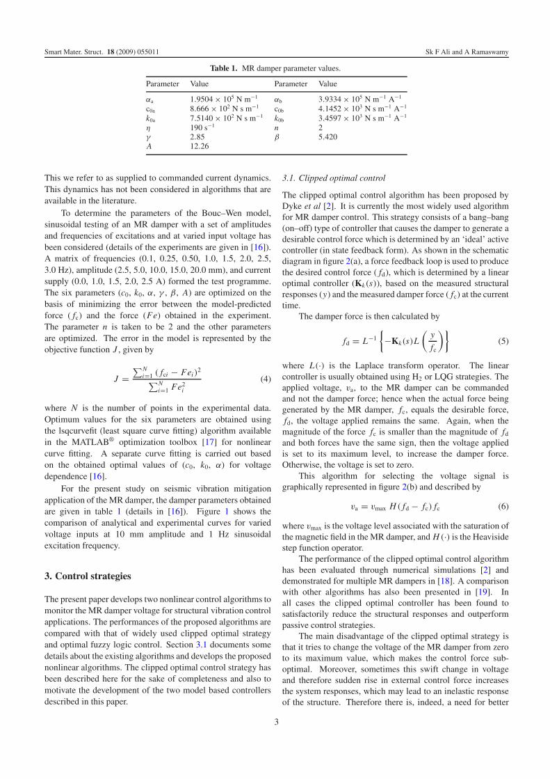
For the present study on seismic vibration mitigationapplication of the MR damper, the damper parameters obtainedare given in table 1 (details in [16]). Figure 1 shows thecomparison of analytical and experimental curves for variedvoltage inputs at 10 mm amplitude and 1 Hz sinusoidalexcitation frequency.
3. Control strategies
The present paper develops two nonlinear control algorithms tomonitor the MR damper voltage for structural vibration controlapplications. The performances of the proposed algorithms arecompared with that of widely used clipped optimal strategyand optimal fuzzy logic control. Section 3.1 documents somedetails about the existing algorithms and develops the proposednonlinear algorithms. The clipped optimal control strategy hasbeen described here for the sake of completeness and also tomotivate the development of the two model based controllersdescribed in this paper.
3.1. Clipped optimal control
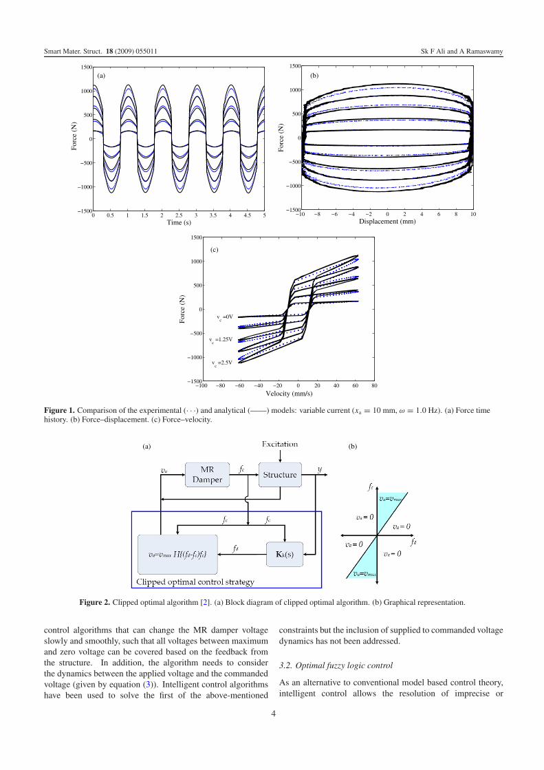
The clipped optimal control algorithm has been proposed byDyke et al [2]. It is currently the most widely used algorithmfor MR damper control. This strategy consists of a bang–bang(on–off) type of controller that causes the damper to generate adesirable control force which is determined by an ‘ideal’ activecontroller (in state feedback form). As shown in the schematicdiagram in figure 2(a), a force feedback loop is used to producethe desired control force ( fd), which is determined by a linearoptimal controller (Kk(s)), based on the measured structuralresponses (y) and the measured damper force ( fc) at the currenttime.
The damper force is then calculated by
fd = L−1
{
−Kk(s)L
(y
fc
)}
(5)
where L(·) is the Laplace transform operator. The linearcontroller is usually obtained using H2 or LQG strategies. Theapplied voltage, va, to the MR damper can be commandedand not the damper force; hence when the actual force beinggenerated by the MR damper, fc, equals the desirable force,fd, the voltage applied remains the same. Again, when themagnitude of the force fc is smaller than the magnitude of fd
and both forces have the same sign, then the voltage appliedis set to its maximum level, to increase the damper force.Otherwise, the voltage is set to zero.
This algorithm for selecting the voltage signal isgraphically represented in figure 2(b) and described by
va = vmax H ( fd − fc) fc (6)
where vmax is the voltage level associated with the saturation ofthe magnetic field in the MR damper, and H (·) is the Heavisidestep function operator.
The performance of the clipped optimal control algorithmhas been evaluated through numerical simulations [2] anddemonstrated for multiple MR dampers in [18]. A comparisonwith other algorithms has also been presented in [19]. Inall cases the clipped optimal controller has been found tosatisfactorily reduce the structural responses and outperformpassive control strategies.
The main disadvantage of the clipped optimal strategy isthat it tries to change the voltage of the MR damper from zeroto its maximum value, which makes the control force sub-optimal. Moreover, sometimes this swift change in voltageand therefore sudden rise in external control force increasesthe system responses, which may lead to an inelastic responseof the structure. Therefore there is, indeed, a need for better
3
Smart Mater. Struct. 18 (2009) 055011 Sk F Ali and A Ramaswamy
(a) (b)
(c)
Figure 1. Comparison of the experimental (· · ·) and analytical (——) models: variable current (xa = 10 mm, ω = 1.0 Hz). (a) Force timehistory. (b) Force–displacement. (c) Force–velocity.
(a) (b)
Figure 2. Clipped optimal algorithm [2]. (a) Block diagram of clipped optimal algorithm. (b) Graphical representation.
control algorithms that can change the MR damper voltageslowly and smoothly, such that all voltages between maximumand zero voltage can be covered based on the feedback fromthe structure. In addition, the algorithm needs to considerthe dynamics between the applied voltage and the commandedvoltage (given by equation (3)). Intelligent control algorithmshave been used to solve the first of the above-mentioned
constraints but the inclusion of supplied to commanded voltagedynamics has not been addressed.
3.2. Optimal fuzzy logic control
As an alternative to conventional model based control theory,intelligent control allows the resolution of imprecise or
4
Smart Mater. Struct. 18 (2009) 055011 Sk F Ali and A Ramaswamy
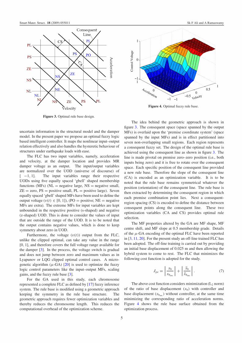
Figure 3. Optimal rule base design.
uncertain information in the structural model and the dampermodel. In the present paper we propose an optimal fuzzy logicbased intelligent controller. It maps the nonlinear input–outputrelation effectively and also handles the hysteretic behaviour ofstructures under earthquake loads with ease.
The FLC has two input variables, namely, accelerationand velocity, at the damper location and provides MRdamper voltage as an output. The input/output variablesare normalized over the UOD (universe of discourse) of[ −1, 1]. The input variables range their respectiveUODs using five equally spaced ‘gbell’ shaped membershipfunctions (MFs) (NL = negative large, NS = negative small,ZE = zero, PS = positive small, PL = positive large). Sevenequally spaced ‘gbell’ shaped MFs have been used to define theoutput voltage (v(t) ∈ [0, 1]), (PO = positive; NE = negativeMFs are extra). The extreme MFs for input variables are keptunbounded in the respective positive (s-shaped) and negative(z-shaped) UOD. This is done to consider the values of inputthat are outside the range of the UOD. It is to be noted thatthe output contains negative values, which is done to keepsymmetry about zero in UOD.
Furthermore, the voltage (v(t)) output from the FLC,unlike the clipped optimal, can take any value in the range[0, 1], and therefore covers the full voltage range available forthe damper [3]. In the process, the voltage switch is gradualand does not jump between zero and maximum values as inLyapunov or LQG clipped optimal control cases. A micro-genetic algorithm (μ-GA) [20] is used to optimize the fuzzylogic control parameters like the input–output MFs, scalinggains, and the fuzzy rule base [3].
For the GA used in this study, each chromosomerepresented a complete FLC as defined by [17] fuzzy inferencesystem. The rule base is modified using a geometric approachkeeping the symmetry in the rule base structure. Thegeometric approach requires fewer optimization variables andthereby reduces the chromosome length. This reduces thecomputational overhead of the optimization scheme.
Acceleration
Con
trol
Vol
tage
Figure 4. Optimal fuzzy rule base.
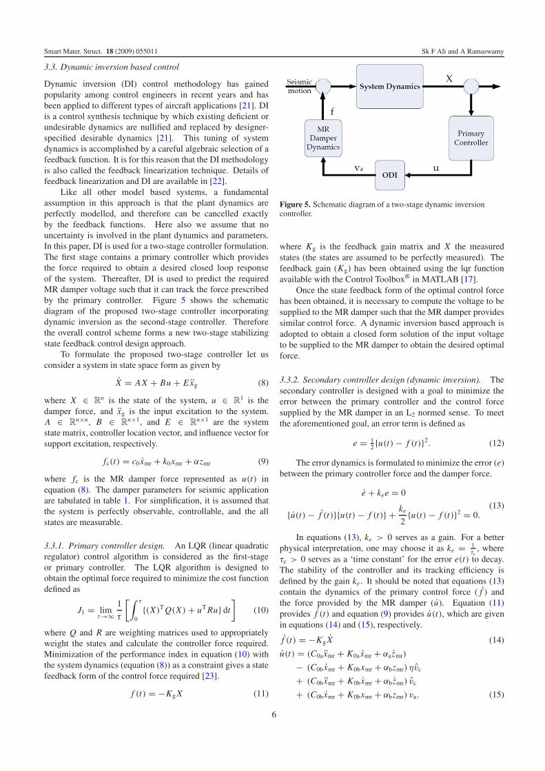
The idea behind the geometric approach is shown infigure 3. The consequent space (space spanned by the outputMFs) is overlaid upon the ‘premise coordinate system’ (spacespanned by the input MFs) and is in effect partitioned intoseven non-overlapping small regions. Each region representsa consequent fuzzy set. The design of the optimal rule base isachieved using the consequent line as shown in figure 3. Theline is made pivotal on premise zero–zero position (i.e., bothinputs being zero) and it is free to rotate over the consequentspace. Each specific position of the consequent line provideda new rule base. Therefore the slope of the consequent line(CA) is encoded as an optimization variable. It is to benoted that the rule base remains symmetrical whatever theposition (orientation) of the consequent line. The rule base isthen extracted by determining the consequent region in whicheach premise combination point lies. Next a consequent-region spacing (CS) is encoded to define the distance betweenconsequent points along the consequent line. These twooptimization variables (CA and CS) provides optimal ruleselection.
The MF properties altered by the GA are MF shape, MFcentre shift, and MF slope at 0.5 membership grade. Detailsof the μ-GA encoding of the optimal FLC have been reportedin [3, 11, 20]. For the present study an off-line trained FLC hasbeen adopted. The off-line training is carried out by providingan initial base displacement of 0.025 m and then allowing thehybrid system to come to rest. The FLC that minimizes thefollowing cost function is adopted for the study.
Jga =∥∥∥∥
xb
xbunc
∥∥∥∥ +
∥∥∥∥
xb
xbunc
∥∥∥∥ . (7)
The above cost function considers minimization (L2 norm)of the ratio of base displacement (xb) with controller andbase displacement (xbunc ) without controller, at the same timeminimizing the corresponding ratio of acceleration norms.Figure 4 shows the rule base surface obtained from theoptimization process.
5
Smart Mater. Struct. 18 (2009) 055011 Sk F Ali and A Ramaswamy
3.3. Dynamic inversion based control
Dynamic inversion (DI) control methodology has gainedpopularity among control engineers in recent years and hasbeen applied to different types of aircraft applications [21]. DIis a control synthesis technique by which existing deficient orundesirable dynamics are nullified and replaced by designer-specified desirable dynamics [21]. This tuning of systemdynamics is accomplished by a careful algebraic selection of afeedback function. It is for this reason that the DI methodologyis also called the feedback linearization technique. Details offeedback linearization and DI are available in [22].
Like all other model based systems, a fundamentalassumption in this approach is that the plant dynamics areperfectly modelled, and therefore can be cancelled exactlyby the feedback functions. Here also we assume that nouncertainty is involved in the plant dynamics and parameters.In this paper, DI is used for a two-stage controller formulation.The first stage contains a primary controller which providesthe force required to obtain a desired closed loop responseof the system. Thereafter, DI is used to predict the requiredMR damper voltage such that it can track the force prescribedby the primary controller. Figure 5 shows the schematicdiagram of the proposed two-stage controller incorporatingdynamic inversion as the second-stage controller. Thereforethe overall control scheme forms a new two-stage stabilizingstate feedback control design approach.
To formulate the proposed two-stage controller let usconsider a system in state space form as given by
X = AX + Bu + Exg (8)
where X ∈ Rn is the state of the system, u ∈ R
1 is thedamper force, and xg is the input excitation to the system.A ∈ R
n×n, B ∈ Rn×1, and E ∈ R
n×1 are the systemstate matrix, controller location vector, and influence vector forsupport excitation, respectively.
fc(t) = c0 xmr + k0xmr + αzmr (9)
where fc is the MR damper force represented as u(t) inequation (8). The damper parameters for seismic applicationare tabulated in table 1. For simplification, it is assumed thatthe system is perfectly observable, controllable, and the allstates are measurable.
3.3.1. Primary controller design. An LQR (linear quadraticregulator) control algorithm is considered as the first-stageor primary controller. The LQR algorithm is designed toobtain the optimal force required to minimize the cost functiondefined as
J1 = limτ→∞
1
τ
[∫ τ
0{(X)T Q(X) + uT Ru} dt
]
(10)
where Q and R are weighting matrices used to appropriatelyweight the states and calculate the controller force required.Minimization of the performance index in equation (10) withthe system dynamics (equation (8)) as a constraint gives a statefeedback form of the control force required [23].
f (t) = −Kg X (11)
Figure 5. Schematic diagram of a two-stage dynamic inversioncontroller.
where Kg is the feedback gain matrix and X the measuredstates (the states are assumed to be perfectly measured). Thefeedback gain (Kg) has been obtained using the lqr functionavailable with the Control Toolbox® in MATLAB [17].
Once the state feedback form of the optimal control forcehas been obtained, it is necessary to compute the voltage to besupplied to the MR damper such that the MR damper providessimilar control force. A dynamic inversion based approach isadopted to obtain a closed form solution of the input voltageto be supplied to the MR damper to obtain the desired optimalforce.
3.3.2. Secondary controller design (dynamic inversion). Thesecondary controller is designed with a goal to minimize theerror between the primary controller and the control forcesupplied by the MR damper in an L2 normed sense. To meetthe aforementioned goal, an error term is defined as
e = 12 {u(t) − f (t)}2. (12)
The error dynamics is formulated to minimize the error (e)between the primary controller force and the damper force.
e + kee = 0
{u(t) − f (t)}{u(t) − f (t)} + ke
2{u(t) − f (t)}2 = 0.
(13)
In equations (13), ke > 0 serves as a gain. For a betterphysical interpretation, one may choose it as ke = 1
τc, where
τc > 0 serves as a ‘time constant’ for the error e(t) to decay.The stability of the controller and its tracking efficiency isdefined by the gain ke. It should be noted that equations (13)contain the dynamics of the primary control force ( f ) andthe force provided by the MR damper (u). Equation (11)provides f (t) and equation (9) provides u(t), which are givenin equations (14) and (15), respectively.
f (t) = −Kg X (14)
u(t) = (C0a xmr + K0a xmr + αa zmr)
− (C0b xmr + K0bxmr + αbzmr) ηvc
+ (C0b xmr + K0bxmr + αb zmr) vc
+ (C0b xmr + K0bxmr + αbzmr) va. (15)
6
Smart Mater. Struct. 18 (2009) 055011 Sk F Ali and A Ramaswamy
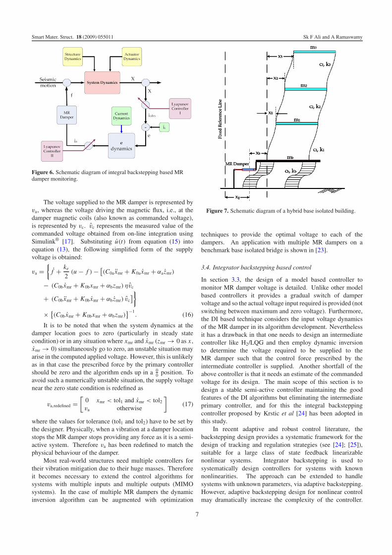
Figure 6. Schematic diagram of integral backstepping based MRdamper monitoring.
The voltage supplied to the MR damper is represented byva, whereas the voltage driving the magnetic flux, i.e., at thedamper magnetic coils (also known as commanded voltage),is represented by vc. vc represents the measured value of thecommanded voltage obtained from on-line integration usingSimulink® [17]. Substituting u(t) from equation (15) intoequation (13), the following simplified form of the supplyvoltage is obtained:
va ={
f + ke
2(u − f ) − [
(C0a xmr + K0a xmr + αa zmr)
− (C0b xmr + K0bxmr + αbzmr) ηvc
+ (C0b xmr + K0bxmr + αb zmr) vc]}
× {(C0b xmr + K0bxmr + αbzmr)
}−1. (16)
It is to be noted that when the system dynamics at thedamper location goes to zero (particularly in steady statecondition) or in any situation where xmr and xmr (zmr → 0 as x ,xmr → 0) simultaneously go to zero, an unstable situation mayarise in the computed applied voltage. However, this is unlikelyas in that case the prescribed force by the primary controllershould be zero and the algorithm ends up in a 0
0 position. Toavoid such a numerically unstable situation, the supply voltagenear the zero state condition is redefined as
va,redefined =[
0 xmr < tol1 and xmr < tol2va otherwise
]
(17)
where the values for tolerance (tol1 and tol2) have to be set bythe designer. Physically, when a vibration at a damper locationstops the MR damper stops providing any force as it is a semi-active system. Therefore va has been redefined to match thephysical behaviour of the damper.
Most real-world structures need multiple controllers fortheir vibration mitigation due to their huge masses. Thereforeit becomes necessary to extend the control algorithms forsystems with multiple inputs and multiple outputs (MIMOsystems). In the case of multiple MR dampers the dynamicinversion algorithm can be augmented with optimization
Figure 7. Schematic diagram of a hybrid base isolated building.
techniques to provide the optimal voltage to each of thedampers. An application with multiple MR dampers on abenchmark base isolated bridge is shown in [23].
3.4. Integrator backstepping based control
In section 3.3, the design of a model based controller tomonitor MR damper voltage is detailed. Unlike other modelbased controllers it provides a gradual switch of dampervoltage and so the actual voltage input required is provided (notswitching between maximum and zero voltage). Furthermore,the DI based technique considers the input voltage dynamicsof the MR damper in its algorithm development. Neverthelessit has a drawback in that one needs to design an intermediatecontroller like H2/LQG and then employ dynamic inversionto determine the voltage required to be supplied to theMR damper such that the control force prescribed by theintermediate controller is supplied. Another shortfall of theabove controller is that it needs an estimate of the commandedvoltage for its design. The main scope of this section is todesign a stable semi-active controller maintaining the goodfeatures of the DI algorithms but eliminating the intermediateprimary controller, and for this the integral backsteppingcontroller proposed by Krstic et al [24] has been adopted inthis study.
In recent adaptive and robust control literature, thebackstepping design provides a systematic framework for thedesign of tracking and regulation strategies (see [24]; [25]),suitable for a large class of state feedback linearizablenonlinear systems. Integrator backstepping is used tosystematically design controllers for systems with knownnonlinearities. The approach can be extended to handlesystems with unknown parameters, via adaptive backstepping.However, adaptive backstepping design for nonlinear controlmay dramatically increase the complexity of the controller.
7
Smart Mater. Struct. 18 (2009) 055011 Sk F Ali and A Ramaswamy
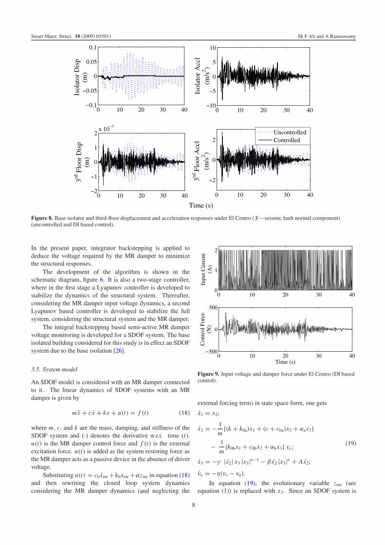
Figure 8. Base isolator and third-floor displacement and acceleration responses under El Centro (X—seismic fault normal component)(uncontrolled and DI based control).
In the present paper, integrator backstepping is applied todeduce the voltage required by the MR damper to minimizethe structural responses.
The development of the algorithm is shown in theschematic diagram, figure 6. It is also a two-stage controller,where in the first stage a Lyapunov controller is developed tostabilize the dynamics of the structural system. Thereafter,considering the MR damper input voltage dynamics, a secondLyapunov based controller is developed to stabilize the fullsystem, considering the structural system and the MR damper.
The integral backstepping based semi-active MR dampervoltage monitoring is developed for a SDOF system. The baseisolated building considered for this study is in effect an SDOFsystem due to the base isolation [26].
3.5. System model
An SDOF model is considered with an MR damper connectedto it. The linear dynamics of SDOF systems with an MRdamper is given by
mx + cx + kx + u(t) = f (t) (18)
where m, c, and k are the mass, damping, and stiffness of theSDOF system and (·) denotes the derivative w.r.t. time (t).u(t) is the MR damper control force and f (t) is the externalexcitation force. u(t) is added as the system restoring force asthe MR damper acts as a passive device in the absence of drivervoltage.
Substituting u(t) = c0xmr + k0xmr +αzmr in equation (18)and then rewriting the closed loop system dynamicsconsidering the MR damper dynamics (and neglecting the
Figure 9. Input voltage and damper force under El Centro (DI basedcontrol).
external forcing term) in state space form, one gets
x1 = x2;
x2 = − 1
m{(k + k0a)x1 + (c + c0a)x2 + αax3}
− 1
m{k0bx1 + c0bx2 + αbx3} vc;
x3 = −γ |x2| x3 |x3|n−1 − β x2 |x3|n + Ax2;vc = −η(vc − va).
(19)
In equation (19), the evolutionary variable zmr (seeequation (1)) is replaced with x3. Since an SDOF system is
8
Smart Mater. Struct. 18 (2009) 055011 Sk F Ali and A Ramaswamy
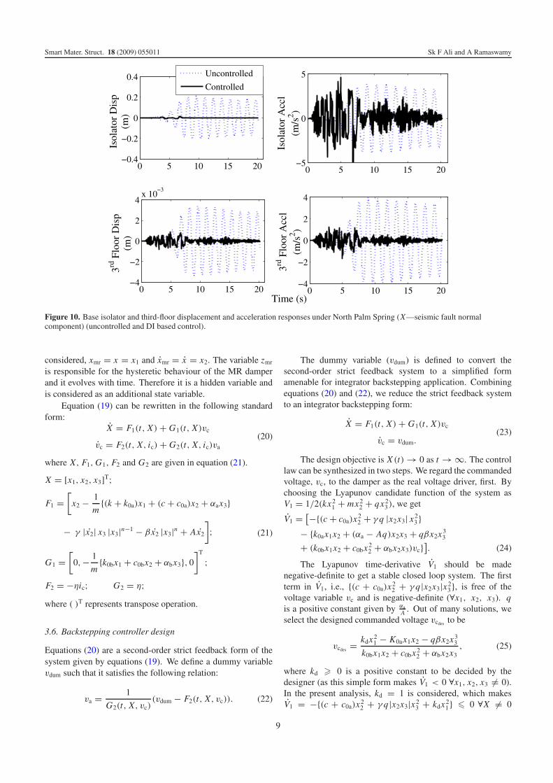
Figure 10. Base isolator and third-floor displacement and acceleration responses under North Palm Spring (X—seismic fault normalcomponent) (uncontrolled and DI based control).
considered, xmr = x = x1 and xmr = x = x2. The variable zmr
is responsible for the hysteretic behaviour of the MR damperand it evolves with time. Therefore it is a hidden variable andis considered as an additional state variable.
Equation (19) can be rewritten in the following standardform:
X = F1(t, X) + G1(t, X)vc
vc = F2(t, X, ic) + G2(t, X, ic)va
(20)
where X, F1, G1, F2 and G2 are given in equation (21).
X = [x1, x2, x3]T;
F1 =[
x2 − 1
m{(k + k0a)x1 + (c + c0a)x2 + αax3}
− γ |x2| x3 |x3|n−1 − β x2 |x3|n + Ax2
]
;
G1 =[
0,− 1
m{k0bx1 + c0bx2 + αbx3}, 0
]T
;
F2 = −ηic; G2 = η;
(21)
where ( )T represents transpose operation.
3.6. Backstepping controller design
Equations (20) are a second-order strict feedback form of thesystem given by equations (19). We define a dummy variablevdum such that it satisfies the following relation:
va = 1
G2(t, X, vc)(vdum − F2(t, X, vc)). (22)
The dummy variable (vdum) is defined to convert thesecond-order strict feedback system to a simplified formamenable for integrator backstepping application. Combiningequations (20) and (22), we reduce the strict feedback systemto an integrator backstepping form:
X = F1(t, X) + G1(t, X)vc
vc = vdum.(23)
The design objective is X (t) → 0 as t → ∞. The controllaw can be synthesized in two steps. We regard the commandedvoltage, vc, to the damper as the real voltage driver, first. Bychoosing the Lyapunov candidate function of the system asV1 = 1/2(kx2
1 + mx22 + qx2
3), we get
V1 = [−{(c + c0a)x22 + γ q |x2x3| x2
3 }− {k0ax1x2 + (αa − Aq)x2x3 + qβx2x3
3
+ (k0bx1x2 + c0bx22 + αbx2x3)vc}
]. (24)
The Lyapunov time-derivative V1 should be madenegative-definite to get a stable closed loop system. The firstterm in V1, i.e., {(c + c0a)x2
2 + γ q|x2x3|x23}, is free of the
voltage variable vc and is negative-definite (∀x1, x2, x3). qis a positive constant given by αa
A . Out of many solutions, weselect the designed commanded voltage vcdes to be
vcdes = kdx21 − K0ax1x2 − qβx2x3
3
k0bx1x2 + c0bx22 + αbx2x3
, (25)
where kd � 0 is a positive constant to be decided by thedesigner (as this simple form makes V1 < 0 ∀x1, x2, x3 �= 0).In the present analysis, kd = 1 is considered, which makesV1 = −{(c + c0a)x2
2 + γ q|x2x3|x23 + kdx2
1} � 0 ∀X �= 0
9
Smart Mater. Struct. 18 (2009) 055011 Sk F Ali and A Ramaswamy
in equation (24). There can be a numerical stability problemwhen all x1 → 0, x2 → 0 and x3 → 0 simultaneously.Therefore, a tolerance is set for all the state variables, belowwhich the damper input voltage is kept at zero.
Nevertheless, vc is a state variable, and perfect trackingto vcdes is desired and hardly achieved in reality. Therefore, anerror variable e (given in equation (26)) as the target error ofthe designed variable is defined.
e = vc − vcdes . (26)
The error dynamics is given by
e = vc − vcdes
= vdum − vcdes,X X (27)
where vcdes,X is the derivative of vcdes w.r.t. state X .Choosing a second Lyapunov function as V2 = V1 + 1
2 e2
and the voltage variable vdum as given in equation (28), it canbe shown that the system defined in equation (23) becomesasymptotically stable (see [22, 24]).
vdum = vcdes,X [F1(t, X) + G1(t, X)vc] − V1,X · G1(t, X)
−K (vc − vcdes ) (28)
with F1 and G1 defined in equation (21); K > 0 is any constantto be decided by the designer. For our analysis K = 1 isconsidered. The voltage applied to the MR damper can beobtained by substituting equation (28) into equation (22).
4. Base isolated building simulation
The aftermaths of the 1994 Northridge and 1995 Kobeearthquakes have resulted in a growing interest amongstructural engineers to evolve systems to protect structuresfrom near-source ground motions. This is because a baseisolation system [26] incorporating rubber bearings alonecannot by itself provide sufficient damping to the structure, andas a consequence the structure experiences large displacementsat the base under pulse type near-field seismic motions.Such excessive displacement can result in a roll-off of thesuperstructure from the supporting structure or collision withnearby structures, resulting in severe structural and equipmentdamage.
For the present simulation study a three-storey baseisolated building is considered. A single MR damper isassumed to be connected at the base of the building, as shownin figure 7. Base isolated buildings are designed such that thesuperstructure remains elastic. Hence, the superstructure ismodelled as a three-dimensional linear elastic shear building.The equations of motion for the elastic superstructure areexpressed in the following form:
MaU + CaU + KaU = −Ma R(Ug + Ub
), (29)
in which M is the superstructure mass matrix, C and K are thesuperstructure damping and stiffness matrices, respectively, inthe fixed-base case, and R is the matrix of earthquake influencecoefficients. Furthermore, U , U , and U represent the flooracceleration, velocity, and displacement vectors relative to thebase, respectively, Ub is the vector of base accelerations (at
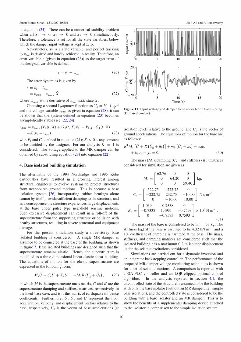
Figure 11. Input voltage and damper force under North Palm Spring(DI based control).
isolation level) relative to the ground, and Ug is the vector ofground accelerations. The equations of motion for the base areas follows:
RT Ma[U + R
(Ug + ub
)] + mb(Ug + ub
) + cbub
+ kbub + fc = 0. (30)
The mass (Ma), damping (Ca), and stiffness (Ka) matricesconsidered for simulation are given as
Ma =[ 62.76 0 0
0 64.20 00 0 59.40
]
kg;
Ca =[ 522.75 −222.75 0
−222.75 232.75 −10.000 −10.00 10.00
]
N s m−1
Ka =[ 1.0394 −0.7338 0
−0.7338 1.4931 −0.75930 −0.7593 0.7593
]
× 106 N m−1.
(31)The mass of the base is considered to be mb = 38 kg. The
stiffness (kb) at the base is assumed to be 4.32 kN m−1 and a1% coefficient of damping is assumed at the base. The mass,stiffness, and damping matrices are considered such that theisolated building has a maximum 0.2 m isolator displacementunder the seismic excitations considered.
Simulations are carried out for a dynamic inversion andan integrator backstepping controller. The performance of theproposed MR damper voltage monitoring techniques is shownfor a set of seismic motions. A comparison is reported witha GA-FLC controller and an LQR-clipped optimal controlalgorithm. In the analysis reported in section 4.1, theuncontrolled state of the structure is assumed to be the buildingwith only the base isolator (without an MR damper, i.e., simplebase isolation), and the controlled state is considered to be thebuilding with a base isolator and an MR damper. This is toshow the benefits of a supplemental damping device attachedto the isolator in comparison to the simple isolation system.
10
Smart Mater. Struct. 18 (2009) 055011 Sk F Ali and A Ramaswamy
(a) (b)
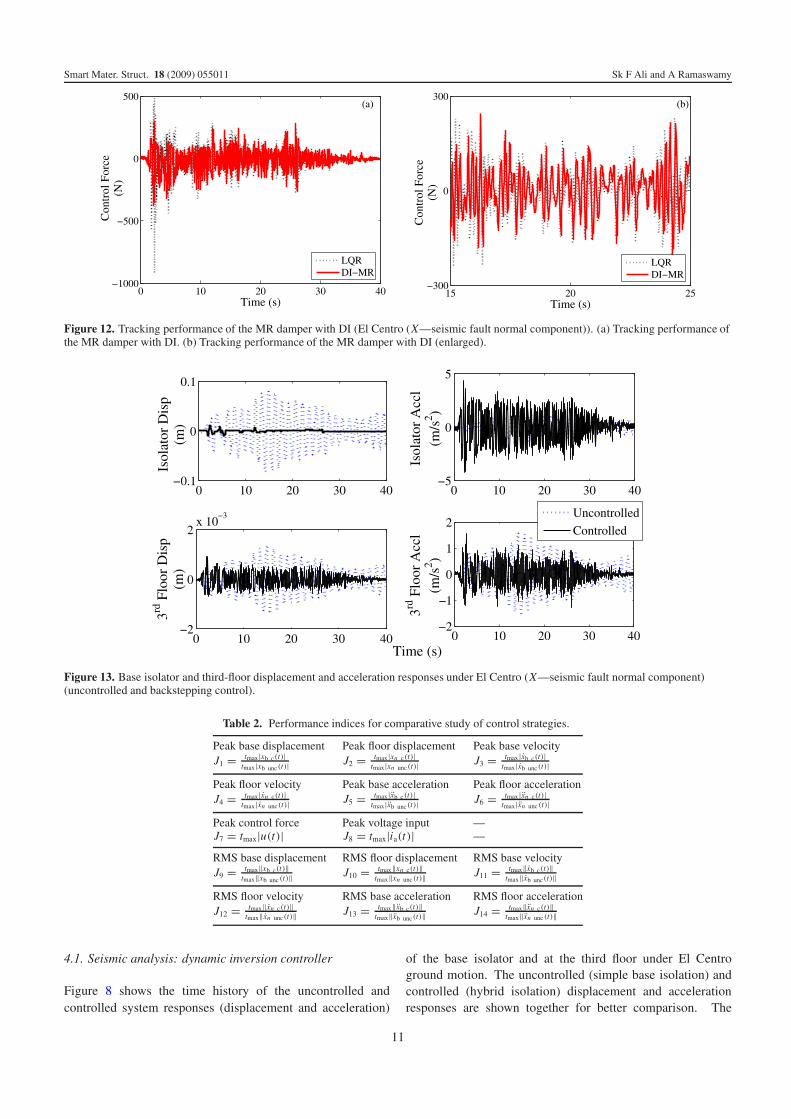
Figure 12. Tracking performance of the MR damper with DI (El Centro (X—seismic fault normal component)). (a) Tracking performance ofthe MR damper with DI. (b) Tracking performance of the MR damper with DI (enlarged).
Figure 13. Base isolator and third-floor displacement and acceleration responses under El Centro (X—seismic fault normal component)(uncontrolled and backstepping control).
Table 2. Performance indices for comparative study of control strategies.
Peak base displacement Peak floor displacement Peak base velocityJ1 = tmax|xb c(t)|
tmax |xb unc(t)| J2 = tmax|xn c(t)|tmax|xn unc(t)| J3 = tmax |xb c(t)|
tmax|xb unc(t)|
Peak floor velocity Peak base acceleration Peak floor accelerationJ4 = tmax|xn c(t)|
tmax |xn unc(t)| J5 = tmax|xb c(t)|tmax|xb unc(t)| J6 = tmax |xn c(t)|
tmax|xn unc (t)|
Peak control force Peak voltage input —J7 = tmax|u(t)| J8 = tmax|ia(t)| —
RMS base displacement RMS floor displacement RMS base velocityJ9 = tmax‖xb c(t)‖
tmax‖xb unc (t)‖ J10 = tmax‖xn c(t)‖tmax‖xn unc(t)‖ J11 = tmax‖xb c(t)‖
tmax‖xb unc(t)‖
RMS floor velocity RMS base acceleration RMS floor accelerationJ12 = tmax‖xn c(t)‖
tmax‖xn unc(t)‖ J13 = tmax‖xb c(t)‖tmax‖xb unc(t)‖ J14 = tmax‖xn c(t)‖
tmax‖xn unc (t)‖
4.1. Seismic analysis: dynamic inversion controller
Figure 8 shows the time history of the uncontrolled andcontrolled system responses (displacement and acceleration)
of the base isolator and at the third floor under El Centroground motion. The uncontrolled (simple base isolation) andcontrolled (hybrid isolation) displacement and accelerationresponses are shown together for better comparison. The
11
Smart Mater. Struct. 18 (2009) 055011 Sk F Ali and A Ramaswamy
peak displacement response of the isolator in the simpleisolation condition is found to be 0.0827 m, which is reducedto 0.0123 m by the DI monitored MR damper. The thirdfloor shows a slight increase in the displacement responsefrom 0.0014 m in the uncontrolled condition to 0.0016 m inthe MR damper controlled case. The acceleration responseat the isolator and at the superstructure is increased dueto the implementation of the MR damper, which is veryusual for hybrid base isolated structures. Since the MRdamper decreases the isolator displacement, the superstructureresponses increase. The base acceleration of 1.5631 m s−2
in the uncontrolled case is increased to 8.2246 m s−2 in theMR controlled case. A drop in the isolator velocity from0.3847 m s−1 in the uncontrolled case to 0.0690 m s−1 in thecontrolled case is also observed.
The control force provided by the MR damper and thecorresponding input voltage to the MR damper are shown infigure 9. It is clear from the input voltage time history that thevoltage supplied reaches the maximum but it also considerscurrent (voltage) values in between zero and maximum 2 A(equivalent to 5 V voltage).
Similar to figure 8, the responses due to the North PalmSpring seismic ground motion are shown in figure 10. Amaximum isolator displacement of 0.2077 m is reduced to0.0113 m. Unlike the case of El Centro seismic ground motion,a better performance of MR damper is observed in the NorthPalm Spring earthquake. The isolator acceleration and thesuperstructure displacement responses are reduced using theMR damper. Only the superstructure acceleration response hasincreased over that of the uncontrolled case.
The control force provided by the MR damper and thecorresponding input voltage to the MR damper in the NorthPalm Spring seismic motion are shown in figure 11. Similarto the El Centro case, the DI based algorithm provides voltagevalues in between the zero and maximum voltage range.
The tracking performance of the DI algorithm for theEl Centro earthquake case is shown in figure 12. Figure 12contains both the force prescribed by the LQR algorithm andthe force provided by the MR damper using input from the DIbased tracking algorithm.
4.2. Seismic analysis: integrator backstepping controller
Base isolated structures behaves as a rigid mass over thebase under seismic ground motion [26]. Therefore SDOFmodels provide a good approximation to these systems forquick calculation under ground motion [26]. The integratorbackstepping based algorithm is developed assuming an SDOFsystem with mass equal to the total mass of the three-storey base isolated building and stiffness equal to that ofthe base stiffness. The tolerance for the simulation studieswith backstepping is set to tol1 = 1 × 10⁻⁵ m for isolatordisplacement and tol2 = 1 × 10⁻⁵ m s−1 for isolator velocity.
Figure 13 shows the time histories of the uncontrolled(simple isolation) and controlled system (hybrid isolation)responses of base isolator and at the third floor under ElCentro ground motion. The uncontrolled and controlleddisplacement and acceleration responses are shown together
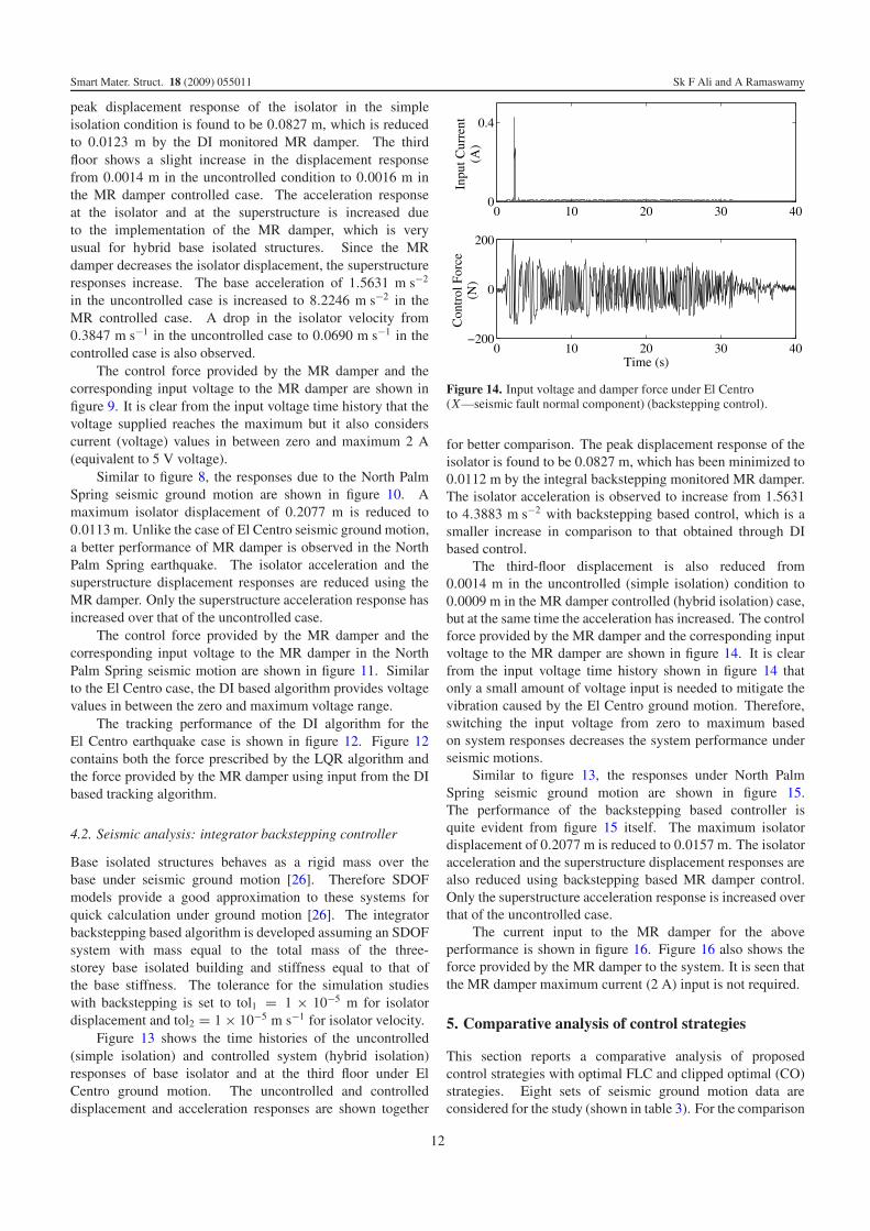
Figure 14. Input voltage and damper force under El Centro(X—seismic fault normal component) (backstepping control).
for better comparison. The peak displacement response of theisolator is found to be 0.0827 m, which has been minimized to0.0112 m by the integral backstepping monitored MR damper.The isolator acceleration is observed to increase from 1.5631to 4.3883 m s−2 with backstepping based control, which is asmaller increase in comparison to that obtained through DIbased control.
The third-floor displacement is also reduced from0.0014 m in the uncontrolled (simple isolation) condition to0.0009 m in the MR damper controlled (hybrid isolation) case,but at the same time the acceleration has increased. The controlforce provided by the MR damper and the corresponding inputvoltage to the MR damper are shown in figure 14. It is clearfrom the input voltage time history shown in figure 14 thatonly a small amount of voltage input is needed to mitigate thevibration caused by the El Centro ground motion. Therefore,switching the input voltage from zero to maximum basedon system responses decreases the system performance underseismic motions.
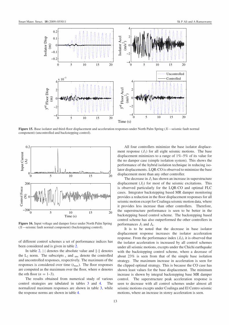
Similar to figure 13, the responses under North PalmSpring seismic ground motion are shown in figure 15.The performance of the backstepping based controller isquite evident from figure 15 itself. The maximum isolatordisplacement of 0.2077 m is reduced to 0.0157 m. The isolatoracceleration and the superstructure displacement responses arealso reduced using backstepping based MR damper control.Only the superstructure acceleration response is increased overthat of the uncontrolled case.
The current input to the MR damper for the aboveperformance is shown in figure 16. Figure 16 also shows theforce provided by the MR damper to the system. It is seen thatthe MR damper maximum current (2 A) input is not required.
5. Comparative analysis of control strategies
This section reports a comparative analysis of proposedcontrol strategies with optimal FLC and clipped optimal (CO)strategies. Eight sets of seismic ground motion data areconsidered for the study (shown in table 3). For the comparison
12
Smart Mater. Struct. 18 (2009) 055011 Sk F Ali and A Ramaswamy
Figure 15. Base isolator and third-floor displacement and acceleration responses under North Palm Spring (X—seismic fault normalcomponent) (uncontrolled and backstepping control).
Figure 16. Input voltage and damper force under North Palm Spring(X—seismic fault normal component) (backstepping control).
of different control schemes a set of performance indices hasbeen considered and is given in table 2.
In table 2, |·| denotes the absolute value and ‖·‖ denotesthe L2 norm. The subscripts c and unc denote the controlledand uncontrolled responses, respectively. The maximum of theresponses is considered over time (tmax). The floor responsesare computed as the maximum over the floor, where n denotesthe nth floor (n = 1–3).
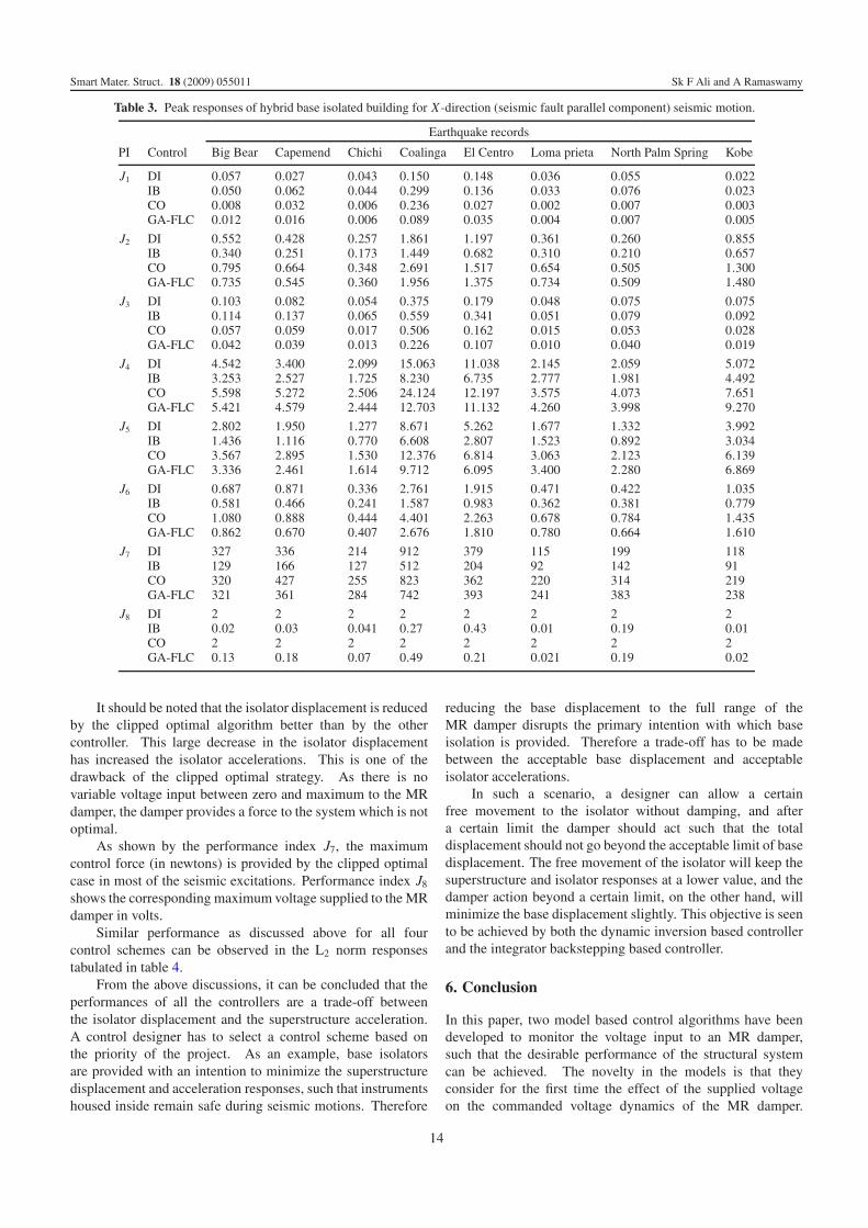
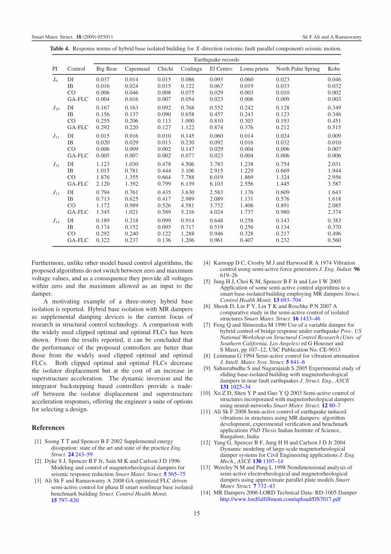
The results obtained from numerical study of variouscontrol strategies are tabulated in tables 3 and 4. Thenormalized maximum responses are shown in table 3, whilethe response norms are shown in table 4.
All four controllers minimize the base isolator displace-ment response (J1) for all eight seismic motions. The basedisplacement minimizes to a range of 1%–5% of its value forthe no damper case (simple isolation system). This shows theperformance of the hybrid isolation technique in reducing iso-lator displacements. LQR-CO is observed to minimize the basedisplacement more than any other controller.
The decrease in J1 has shown an increase in superstructuredisplacement (J2) for most of the seismic excitations. Thisis observed particularly for the LQR-CO and optimal FLCcases. Integrator backstepping based MR damper monitoringprovides a reduction in the floor displacement responses for allseismic motion except for Coalinga seismic motion data, whereit provides less increase than other controllers. Therefore,the superstructure performance is seen to be better in thebackstepping based control scheme. The backstepping basedcontrol scheme has also outperformed the other controllers inperformances J3 and J4.
It is to be noted that the decrease in base isolatordisplacement response increases the isolator accelerationresponse. From the performance index (J5), it is observed thatthe isolator acceleration is increased by all control schemesunder all seismic motions, excepts under the Chichi earthquakewith the backstepping control scheme, where a decrease ofabout 23% is seen from that of the simple base isolationstrategy. The maximum increase in acceleration is seen forthe clipped optimal strategy. This is because the CO case hasshown least values for the base displacement. The minimumincrease is shown by integral backstepping base MR dampercontrol. The superstructure peak acceleration response isseen to decrease with all control schemes under almost allseismic motions excepts under Coalinga and El Centro seismicmotions, where an increase in storey acceleration is seen.
13
Smart Mater. Struct. 18 (2009) 055011 Sk F Ali and A Ramaswamy
Table 3. Peak responses of hybrid base isolated building for X-direction (seismic fault parallel component) seismic motion.
Earthquake records
PI Control Big Bear Capemend Chichi Coalinga El Centro Loma prieta North Palm Spring Kobe
J1 DI 0.057 0.027 0.043 0.150 0.148 0.036 0.055 0.022IB 0.050 0.062 0.044 0.299 0.136 0.033 0.076 0.023CO 0.008 0.032 0.006 0.236 0.027 0.002 0.007 0.003GA-FLC 0.012 0.016 0.006 0.089 0.035 0.004 0.007 0.005
J2 DI 0.552 0.428 0.257 1.861 1.197 0.361 0.260 0.855IB 0.340 0.251 0.173 1.449 0.682 0.310 0.210 0.657CO 0.795 0.664 0.348 2.691 1.517 0.654 0.505 1.300GA-FLC 0.735 0.545 0.360 1.956 1.375 0.734 0.509 1.480
J3 DI 0.103 0.082 0.054 0.375 0.179 0.048 0.075 0.075IB 0.114 0.137 0.065 0.559 0.341 0.051 0.079 0.092CO 0.057 0.059 0.017 0.506 0.162 0.015 0.053 0.028GA-FLC 0.042 0.039 0.013 0.226 0.107 0.010 0.040 0.019
J4 DI 4.542 3.400 2.099 15.063 11.038 2.145 2.059 5.072IB 3.253 2.527 1.725 8.230 6.735 2.777 1.981 4.492CO 5.598 5.272 2.506 24.124 12.197 3.575 4.073 7.651GA-FLC 5.421 4.579 2.444 12.703 11.132 4.260 3.998 9.270
J5 DI 2.802 1.950 1.277 8.671 5.262 1.677 1.332 3.992IB 1.436 1.116 0.770 6.608 2.807 1.523 0.892 3.034CO 3.567 2.895 1.530 12.376 6.814 3.063 2.123 6.139GA-FLC 3.336 2.461 1.614 9.712 6.095 3.400 2.280 6.869
J6 DI 0.687 0.871 0.336 2.761 1.915 0.471 0.422 1.035IB 0.581 0.466 0.241 1.587 0.983 0.362 0.381 0.779CO 1.080 0.888 0.444 4.401 2.263 0.678 0.784 1.435GA-FLC 0.862 0.670 0.407 2.676 1.810 0.780 0.664 1.610
J7 DI 327 336 214 912 379 115 199 118IB 129 166 127 512 204 92 142 91CO 320 427 255 823 362 220 314 219GA-FLC 321 361 284 742 393 241 383 238
J8 DI 2 2 2 2 2 2 2 2IB 0.02 0.03 0.041 0.27 0.43 0.01 0.19 0.01CO 2 2 2 2 2 2 2 2GA-FLC 0.13 0.18 0.07 0.49 0.21 0.021 0.19 0.02
It should be noted that the isolator displacement is reducedby the clipped optimal algorithm better than by the othercontroller. This large decrease in the isolator displacementhas increased the isolator accelerations. This is one of thedrawback of the clipped optimal strategy. As there is novariable voltage input between zero and maximum to the MRdamper, the damper provides a force to the system which is notoptimal.
As shown by the performance index J7, the maximumcontrol force (in newtons) is provided by the clipped optimalcase in most of the seismic excitations. Performance index J8
shows the corresponding maximum voltage supplied to the MRdamper in volts.
Similar performance as discussed above for all fourcontrol schemes can be observed in the L2 norm responsestabulated in table 4.
From the above discussions, it can be concluded that theperformances of all the controllers are a trade-off betweenthe isolator displacement and the superstructure acceleration.A control designer has to select a control scheme based onthe priority of the project. As an example, base isolatorsare provided with an intention to minimize the superstructuredisplacement and acceleration responses, such that instrumentshoused inside remain safe during seismic motions. Therefore
reducing the base displacement to the full range of theMR damper disrupts the primary intention with which baseisolation is provided. Therefore a trade-off has to be madebetween the acceptable base displacement and acceptableisolator accelerations.
In such a scenario, a designer can allow a certainfree movement to the isolator without damping, and aftera certain limit the damper should act such that the totaldisplacement should not go beyond the acceptable limit of basedisplacement. The free movement of the isolator will keep thesuperstructure and isolator responses at a lower value, and thedamper action beyond a certain limit, on the other hand, willminimize the base displacement slightly. This objective is seento be achieved by both the dynamic inversion based controllerand the integrator backstepping based controller.
6. Conclusion
In this paper, two model based control algorithms have beendeveloped to monitor the voltage input to an MR damper,such that the desirable performance of the structural systemcan be achieved. The novelty in the models is that theyconsider for the first time the effect of the supplied voltageon the commanded voltage dynamics of the MR damper.
14
Smart Mater. Struct. 18 (2009) 055011 Sk F Ali and A Ramaswamy
Table 4. Response norms of hybrid base isolated building for X-direction (seismic fault parallel component) seismic motion.
Earthquake records
PI Control Big Bear Capemend Chichi Coalinga El Centro Loma prieta North Palm Spring Kobe
J9 DI 0.037 0.014 0.015 0.086 0.093 0.060 0.023 0.046IB 0.016 0.024 0.015 0.122 0.067 0.019 0.033 0.032CO 0.006 0.046 0.008 0.075 0.029 0.003 0.010 0.002GA-FLC 0.004 0.016 0.007 0.054 0.023 0.006 0.009 0.003
J10 DI 0.167 0.163 0.092 0.768 0.552 0.242 0.128 0.349IB 0.156 0.137 0.090 0.658 0.457 0.243 0.123 0.346CO 0.255 0.206 0.113 1.000 0.810 0.303 0.193 0.451GA-FLC 0.292 0.220 0.127 1.122 0.874 0.376 0.212 0.515
J11 DI 0.015 0.016 0.010 0.145 0.060 0.014 0.024 0.009IB 0.020 0.029 0.013 0.230 0.092 0.016 0.032 0.010CO 0.006 0.009 0.002 0.147 0.029 0.004 0.006 0.007GA-FLC 0.005 0.007 0.002 0.077 0.023 0.004 0.006 0.006
J12 DI 1.123 1.030 0.478 4.506 3.783 1.238 0.754 2.031IB 1.015 0.781 0.444 3.106 2.915 1.229 0.669 1.944CO 1.876 1.355 0.664 7.788 6.019 1.869 1.324 2.956GA-FLC 2.120 1.392 0.799 6.139 6.103 2.556 1.445 3.587
J13 DI 0.794 0.761 0.435 3.630 2.583 1.176 0.609 1.643IB 0.713 0.625 0.417 2.989 2.089 1.131 0.576 1.618CO 1.172 0.989 0.526 4.581 3.732 1.406 0.891 2.085GA-FLC 1.345 1.021 0.589 5.216 4.024 1.737 0.980 2.374
J14 DI 0.189 0.218 0.099 0.914 0.648 0.258 0.143 0.383IB 0.174 0.152 0.095 0.717 0.519 0.256 0.134 0.370CO 0.292 0.240 0.122 1.288 0.946 0.328 0.217 0.496GA-FLC 0.322 0.237 0.136 1.206 0.961 0.407 0.232 0.560
Furthermore, unlike other model based control algorithms, theproposed algorithms do not switch between zero and maximumvoltage values, and as a consequence they provide all voltageswithin zero and the maximum allowed as an input to thedamper.
A motivating example of a three-storey hybrid baseisolation is reported. Hybrid base isolation with MR dampersas supplemental damping devices is the current focus ofresearch in structural control technology. A comparison withthe widely used clipped optimal and optimal FLCs has beenshown. From the results reported, it can be concluded thatthe performance of the proposed controllers are better thanthose from the widely used clipped optimal and optimalFLCs. Both clipped optimal and optimal FLCs decreasethe isolator displacement but at the cost of an increase insuperstructure acceleration. The dynamic inversion and theintegrator backstepping based controllers provide a trade-off between the isolator displacement and superstructureacceleration responses, offering the engineer a suite of optionsfor selecting a design.
References
[1] Soong T T and Spencer B F 2002 Supplemental energydissipation: state of the art and state of the practice Eng.Struct. 24 243–59
[2] Dyke S J, Spencer B F Jr, Sain M K and Carlson J D 1996Modeling and control of magnetorheological dampers forseismic response reduction Smart Mater. Struct. 5 565–75
[3] Ali Sk F and Ramaswamy A 2008 GA optimized FLC drivensemi-active control for phase II smart nonlinear base isolatedbenchmark building Struct. Control Health Monit.15 797–820
[4] Karnopp D C, Crosby M J and Harwood R A 1974 Vibrationcontrol using semi-active force generators J. Eng. Indust. 96619–26
[5] Jung H J, Choi K M, Spencer B F Jr and Lee I W 2005Application of some semi-active control algorithms to asmart base-isolated building employing MR dampers Struct.Control Health Monit. 13 693–704
[6] Shook D, Lin P Y, Lin T K and Roschke P N 2007 Acomparative study in the semi-active control of isolatedstructures Smart Mater. Struct. 16 1433–46
[7] Feng Q and Shinozuka M 1990 Use of a variable damper forhybrid control of bridge response under earthquake Proc. USNational Workshop on Structural Control Research (Univ. ofSouthern California, Los Angeles) ed G Housner andS Masri, pp 107–12, USC Publication No. CE-9013
[8] Leitmann G 1994 Semi-active control for vibration attenuationJ. Intell. Mater. Syst. Struct. 5 841–6
[9] Sahasrabudhe S and Nagarajaiah S 2005 Experimental study ofsliding base-isolated building with magnetorheologicaldampers in near fault earthquakes J. Struct. Eng., ASCE131 1025–34
[10] Xu Z D, Shen Y P and Guo Y Q 2003 Semi-active control ofstructures incorporated with magnetorheological dampersusing neural-networks Smart Mater. Struct. 12 80–7
[11] Ali Sk F 2008 Semi-active control of earthquake inducedvibrations in structures using MR dampers: algorithmdevelopment, experimental verification and benchmarkapplications PhD Thesis Indian Institute of Science,Bangalore, India
[12] Yang G, Spencer B F, Jung H H and Carlson J D Jr 2004Dynamic modeling of large-scale magnetorheologicaldamper systems for Civil Engineering applications J. Eng.Mech., ASCE 130 1107–14
[13] Wereley N M and Pang L 1998 Nondimensional analysis ofsemi-active electrorheological and magnetorheologicaldampers using approximate parallel plate models SmartMater. Struct. 7 732–43
[14] MR Dampers 2006 LORD Technical Data: RD-1005 Damperhttp://www.lordfulfillment.com/upload/DS7017.pdf
15
Smart Mater. Struct. 18 (2009) 055011 Sk F Ali and A Ramaswamy
[15] Spencer B F Jr, Dyke S J, Sain M K and Carlson J D 1997Phenomenological model for magnetorheological dampersJ. Eng. Mech., ASCE 123 230–8
[16] Ali Sk F and Ramaswamy A 2009 Testing and modeling of MRdamper and its application to SDOF systems using integralbackstepping technique Trans. ASME J. Dyn. Syst. Meas.Control 131 021009
[17] MATLAB 2004 The Software for Numerical Computing,Version 7.0.1 (R 14) The MathWorks http://www.mathworks.com/index.html?ref=pt
[18] Jansen L M and Dyke S J 1999 Investigation of nonlinearcontrol strategies for the implementation of multiplemagnetorheological dampers 1999 ASCE EngineeringMechanics Conf. (Baltimore, MD, June)
[19] Jansen L M and Dyke S J 2000 Semiactive control strategies forMR dampers: comparative study J. Eng. Mech., ASCE126 795–803
[20] Ali Sk F and Ramaswamy A 2008 Optimal fuzzy logic controlfor MDOF structural systems using evolutionary algorithms
Eng. Appl. Artif. Intell., IFACdoi:10.1016/j.engappai.2008.09.004
[21] Reiner J, Balas G J and Garrard W L 1995 Robust dynamicinversion for control of highly maneuverable aircraftJ. Guid., Control, Dyn. 18 18–24
[22] Marquez H J 2003 Nonlinear Control Systems: Analysis andDesign (New York: Wiley Interscience)
[23] Ali Sk F and Ramaswamy A 2009 Optimal dynamic inversionbased semi-active control of benchmark bridge using MRdampers Struct. Control Health Monit. at press(doi:10.1002/stc.325)
[24] Krstic M, Kanellakopoulos I and Kokotovic P V 1995Nonlinear and Adaptive Control Design (New York: Wiley)
[25] Krstic M and Smyshlyaev A 2007 Backstepping boundarycontrol—a tutorial Proc. American Control Conf.(New York City, NY, July) pp 870–5
[26] Chopra A K 2005 Dynamics of Structures: Theory andApplication to Earthquake Engineering (New Delhi:Pearson Education)
16