hybrid systems modeling challenges caused by...
TRANSCRIPT

Hybrid Systems Modeling ChallengesCaused by Cyber-Physical Systems?
Albert Benveniste1, Timothy Bourke2,3,??,Benoıt Caillaud1, and Marc Pouzet2,4,3,??
1 INRIA Rennes, Campus de Beaulieu, 35042 Rennes cedex, France2 DI, Ecole normale superieure, 45 rue d’Ulm, 75230 Paris cedex, France
3 INRIA Paris-Rocquencourt4 Univ. Pierre et Marie Curie
Abstract. Hybrid systems exhibit mode-dependent continuous-time dy-namics. They are encountered in several phases of Cyber-Physical Sys-tems design: physical system modeling, budgeting time over the com-puting architecture, safety analyses, and more generally virtual systemmodeling. These different phases typically involve different kinds of tools,with differing interpretations of the underlying mathematics. By exhibit-ing a mix of continuous- and discrete-time, hybrid systems raise a numberof unexpected challenges for existing modeling and simulation tools.
We review these challenges and propose some new perspectives for ad-dressing them. Recalling the theoretical effort that underpinned the de-velopment of synchronous languages—which allowed, for example, thedevelopment of a certified compiler for SCADE—we propose redoing thesame for hybrid systems modeling tools.
Keywords: Cyber-Physical Systems, Hybrid Systems, physical systemmodeling, ODE, DAE, nonstandard semantics
1 Introduction: virtual engineering in CPS
By combining possibly distributed physical objects and devices together withthe embedded or remote computing systems for their control, Cyber-Physicalsystems (CPS) [12,33] elevate issues of modeling to a very demanding level. Asa real example, we know of a system design toolset in use at an automotivecompany which had to:
– help over 30 different internal teams with diverse expertise work together;– link over 40 different embedded electronics design representations across the
entire development process;
? This work was supported by Action d’Envergure INRIA Synchronics and by ITEA-project MODRIO.
?? PARKAS project team, Departement d’Informatique de l’Ecole normale superieure,(ENS/INRIA/CNRS UMR 8548).

2 Benveniste et al.
– ensure the integration of the embedded electronics design flow at the samelevels of quality and performance as the 3D CAD system;
– support model-based design and executable specification throughout theOEM/supplier chain.
Since they involve physical objects and devices, CPS require a lot of multi-physicsmodeling, ranging across mechanics, aerodynamics, hydraulics, thermodynam-ics, electrical, and combinations thereof. Since CPS cannot go without control, anumber of functions must be specified for CPS control, monitoring, and supervi-sion. These functions are initially specified during requirements capture and thenlater refined to embedded system software. CPS are a combination of physicalsystems for control, with associated embedded software running on a possiblydistributed embedded computing architecture comprising ECUs and communi-cation/OS infrastructure, with resource characteristics (time, energy, memory,weight) that usually require optimization. CPS models should, therefore, encom-pass all of the above aspects. Issues of quality and certification call for executableand analyzable models, with reproducible executions free from unwanted non-determinism. This “models everywhere” design philosophy is advocated by A.Sangiovanni-Vincentelli under the name of Platform Based Design [35,9,32].
Recalling the theoretical effort that was performed in support of the develop-ment of synchronous languages [7] and which facilitated, for example, facilitatedthe creation of a certified compiler for SCADE,5 we would like to redo the samefor hybrid systems modeling tools. Clean semantic definitions are, therefore, oneimportant aspect that we discuss. The status of discrete-time/discrete-event dy-namics embedded in continuous time systems is another central issue that westudy. We advocate the use of a clear identification of continuous versus discreteclocks and signals and we suggest regarding this issue as part of compilation bygiving it the form of a typing problem. This allows us to propose a novel slicedarchitecture for hybrid systems modelers, consisting of off-the-shelf ODE solvers,an off-the-shelf synchronous compiler, and a small controller that coordinates thetwo.
The paper is organized as follows. Consequences for Hybrid Systems Model-ing in CPS is discussed in Section 2. We observe that discrete and continuousdynamics may be understood in different ways depending on the type of tool.We therefore discuss the issue of discrete dynamics in the context of continuousdynamics. Then, we discuss some difficult problems related to this distinctionthat arise from the physics. Section 3 reviews the corresponding fundamentalchallenges. We briefly describe the concept of slicing. Then, we motivate theconsideration of nonstandard analysis as a semantics domain for hybrid systems.In Section 4 we sketch some details of our proof-of-concept hybrid synchronouslanguage Zelus. Finally, the consideration of acausal systems is discussed in Sec-tion 5, as well as some other novel issues raised by hybrid systems.
5 http://www.esterel-technologies.com
Hybrid Systems Modeling Challenges Caused by CPS 3
2 Consequences for Hybrid Systems Modeling in CPS
The multi-faceted nature of modeling in CPS design raises a number of novelissues that we discuss in this section.
2.1 Do the different modeling tools speak the same mathematicallanguage?
From the point of view of modeling and simulation tools, one must identify thekey basic Models of Computation used for different design tasks:6
– The continuous real time of physics is used for physical systems modeling,for the timing behavior of computing architectures, and also for the finetiming behavior of the entire system.
– Discrete time is used to enumerate successive events of the same kind. It canbe metric when dealing with sampled control, or event based in supervisionfunctions, where, for example, reconfiguration or mode change occurs inresponse to certain events.
– Resource models are required to address resource management (timing bud-gets, energy consumption, weight, cost, etc.).
These models of computation are interspersed throughout designs. Discrete-timeis used to capture events or sampled time in multi-physics modeling, to triggerCPS functions in embedded software, and also in resource models. Continuousreal-time is used in multi-physics modeling, in resource modeling, and, to alesser extent, in the modeling of computing architectures. And, finally, resourcemodels are also used to deal with resource issues in physical parts and devices.Unfortunately the various tools used for these different tasks do not alwaysinterpret the models of computation in a consistent way.
Models of systems involving the physics are typically built using Simulinkand related tools,7 Labview8, or Modelica.9 In these models, the current statusis to regard discrete-time/event models as continuous-time ones having piecewiseconstant trajectories. The same tools can be used for capturing pure discrete-time/event models of the embedded software and SCADE offers a certified com-piler for it. For this restricted use, it makes sense to regard trajectories as se-quences or streams of valued events, not continuous-time trajectories. Models
6 Models of Computation are the heart of E.A. Lee’s Ptolemy II tool for multi-domainsystem modeling [16,12,15].
7 Stateflow (http://www.mathworks.fr/products/stateflow/) for higher-levelevent-based specification of functions; SimEvents (http://www.mathworks.fr/products/simevents/) for the timing evaluation of architectures; Simscape(http://www.mathworks.fr/products/simscape/) for physical modeling witha number of dedicated tools for each domain; Simulink Coder (http://www.mathworks.fr/products/simulink-coder/) for code generation with several spe-cializations; and, xPC Target (http://www.mathworks.fr/products/xpctarget/)for rapid prototyping and HIL simulation, with again some specializations.
8 http://www.ni.com/labview/ and [28,19]9 http://www.modelica.org/

4 Benveniste et al.
of discrete time or discrete events used for timing/performance evaluation ofcomputing architectures, or for safety analyzes, may also differ.
2.2 The Problem with Continuous versus Discrete
We will focus our discussion on the two seemingly simple domains of discretetime and continuous real time, as they are handled in most popular tools.10
For a simple example, consider the program shown in Figure 1, written ina self-explanatory “programming language”. This program specifies a discrete-
S = pre (S) init 0.0 + x (i)x = 1.0 init 0.0 (ii)
(a)
(b)
(c)
(d)
Fig. 1: A basic program and its possible interpretations. Activations of thediscrete-time block are marked by triangles and the corresponding outputs Sby circles.
time accumulator S, which successively sums the values received on the inputsignal x; pre (S) denotes the previous value of S with an initial value of 0.0. Thisis a discrete-time dynamical system, which makes perfect sense when consideredin isolation. But it is composed with the second equation: an ODE defining x.Clearly, this is a spurious program as it mixes the discrete-time equation defining
10 It is not our intention to criticize any particular tool. The ones we discuss are allhigh-quality, widely-used tools with recurrent successful applications in industry. Wesimply try, rather, to indicate the surprising difficulties of the subject.

Hybrid Systems Modeling Challenges Caused by CPS 5
Unit Delay
z
1
ScopeIntegrator
1
s
Constant
1
Add
cpt
time
(a) With a ‘Unit Delay’ block
ScopeMemory
Integrator
1
s
Constant
1
Add
cpt
time
(b) With a ‘Memory’ block0 0.5 1 1.5 2 2.5 3
0
10
20
30
40
50
60
70
80
Time
(c) Variable-step solver (ode45)
Fig. 2: Simulink models with problematic combinations of continuous and dis-crete blocks.
S with the continuous time ODE x = . . . Some interpretations of this programare proposed in Figure 1:11
(a) Here, N is taken as the time base for activating the discrete-time equation(i), using the natural embedding N ⊆ R. The question is, then: why preferthis embedding over any other, for example, one that activates the programevery millisecond rather than every second?
(b) Alternatively, since the discrete-time equation (i) is not given a proper acti-vation clock, it inherits the discrete sequence of discretization instants chosenby a continuous solver (the so-called “major steps” of Simulink [27, 3-19][26,4-80]). Thus, in this interpretation, assuming a variable step size solver isused for the ODE, the instants of activation of the discrete-time block effec-tively become unpredictable, as does the behavior of the whole program.
(c) Another possibility is for the discrete-time block to inherit the “zero-duration”perpendicular time of the super-dense semantics advocated by E.A. Lee [25,22,23].That is, the discrete-time equation (i) is activated at an infinite pace, so allinstants accumulate as a totally ordered sequence arising at physical timet = 0. Obviously, the accumulator S diverges immediately.
(d) Another interpretation, not shown in the figure, consists in rejecting this pro-gram at compile time, by using a typing analysis that considers continuous-time variable time as an invalid input for the discrete-time equation (i).
(e) Here we have corrected the typing inconsistency of the program by makingthe activation instants of the discrete-time block explicit as the zero-crossingsof the continuous-time signal shown in green.
The reader may wonder what would happen if such a spurious program issubmitted to a real hybrid systems modeler. Figure 2a shows the correspondingSimulink model. At the beginning of a simulation, Simulink prints the warning:
11 Each of these interpretations is invoked in one way or another in popular tools forsome programs.

6 Benveniste et al.
Integrator
1s
54
DisplayConstant
1
Chart
t cpt
(a) Simulink model
s1{cpt := 0}
[t<=42]{cpt := cpt + 1}
(b) Stateflow Chart
Fig. 3: A Simulink/Stateflow model with a problematic combination of continu-ous and discrete behaviors.
Warning: ‘Unit Delay’ is discrete, yet is inheriting a continuous sampletime; consider replacing unit delay with a memory block. When a unitdelay block inherits continuous sample time, its behavior is the same asthe memory block. Unit delay block’s time delay will not be fixed andcould change with each time step. This might be unexpected behavior.Normally, a unit delay block uses discrete sample time. You can disablethis diagnostic by setting the “Discrete used as continuous” diagnosticto “none” in the Sample Time group on the Diagnostics panel of theConfiguration Parameters dialog box.
Following this suggestion yields the model in Figure 2b which executes withoutrelated warnings. Simulating either model over three seconds gives the resultsshown in Figure 2c. So, Simulink responds to such diagrams with warnings andsuggestions. There may be many such messages, and, generally the appropriateresponse can be found amongst them. Unfortunately, knowing which is the rightanswer generally requires knowing very precisely how the diagram is supposed tobehave. . . something that, indeed, a designer wants to learn from a simulation.
There are also cases where spurious models are accepted without any warn-ing. One such example is shown in Figure 3, which comprises a top-level Simulinkmodel, Figure 3a, that contains a (continuous) Stateflow chart, Figure 3b. Thischart increments the counter cpt for as long as the input t, generated by anintegrator, is less than an arbitrary constant. The value of the counter againdepends on the steps chosen by the solver, but no warning message is emitted.
Properly separating continuous-time and discrete-time dynamics is not sim-ple. The Modelica consortium12 is currently endeavouring to isolate and cleanlyorchestrate, in the context of integrated virtual modeling, discrete reactions,continuous real time, and continuous dynamics [18,29]. Ptolemy II13, on theother hand, delegates the combination of different models to so-called directors,which specify and implement, through user defined protocols, the coordinationof different models of computation. In continuous-time models, the director in-vokes numerical solvers. In both cases, and in other tools, such combinations ofcontinuous-time and discrete-time dynamics involve many delicate choices whichaffect the meaning of models. Overall, we believe that cleanly separating, in hy-
12 https://www.openmodelica.org/13 http://ptolemy.berkeley.edu/ptolemyII/
Hybrid Systems Modeling Challenges Caused by CPS 7
(a) Billiards (b) Circuit breakers
(c) Braking systems (d) Human hair
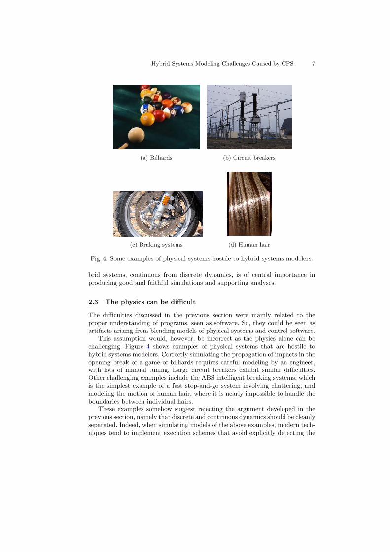
Fig. 4: Some examples of physical systems hostile to hybrid systems modelers.
brid systems, continuous from discrete dynamics, is of central importance inproducing good and faithful simulations and supporting analyses.
2.3 The physics can be difficult
The difficulties discussed in the previous section were mainly related to theproper understanding of programs, seen as software. So, they could be seen asartifacts arising from blending models of physical systems and control software.
This assumption would, however, be incorrect as the physics alone can bechallenging. Figure 4 shows examples of physical systems that are hostile tohybrid systems modelers. Correctly simulating the propagation of impacts in theopening break of a game of billiards requires careful modeling by an engineer,with lots of manual tuning. Large circuit breakers exhibit similar difficulties.Other challenging examples include the ABS intelligent breaking systems, whichis the simplest example of a fast stop-and-go system involving chattering, andmodeling the motion of human hair, where it is nearly impossible to handle theboundaries between individual hairs.
These examples somehow suggest rejecting the argument developed in theprevious section, namely that discrete and continuous dynamics should be cleanlyseparated. Indeed, when simulating models of the above examples, modern tech-niques tend to implement execution schemes that avoid explicitly detecting the

8 Benveniste et al.
discrete events defining changes in the continuous dynamics, see, for example,the so-called Moreau’s Sweeping Process [21,2], which is discussed in Section 5.2.
So, the issue becomes the following: how to slice a program into
– its solver-handled part, and– its discrete-handled part.
The solver-handled part gathers the dynamics that are to be delegated to asolver. As the above discussion indicates, this fragment may include some dis-continuities. Other discontinuities—we call them stopping events—must notbe handled by the solver, but are instead delegated to the discrete-handled part,which triggers resets, reconfigurations, and, more generally, mode changes.
As an example, a bouncing ball seen as an isolated system, could be com-pletely delegated to a solver for simulation, see [1] for a numerical examplewhere simulation is performed without explicit detection of bouncing events. Incontrast, if the bouncing event occurs in a game in Las Vegas, then jackpotmay result, and this event becomes more important and must be handled as astopping event because it triggers some mode change in another subsystem (theplayer’s pocket).
In summary, properly identifying stopping events at compile time is a criticaltask of the compiler.
3 The Need for an Effort on Theory
Here we provide a high-level presentation of technical results that can be foundin detail in [6].
3.1 Compilation by Code Slicing
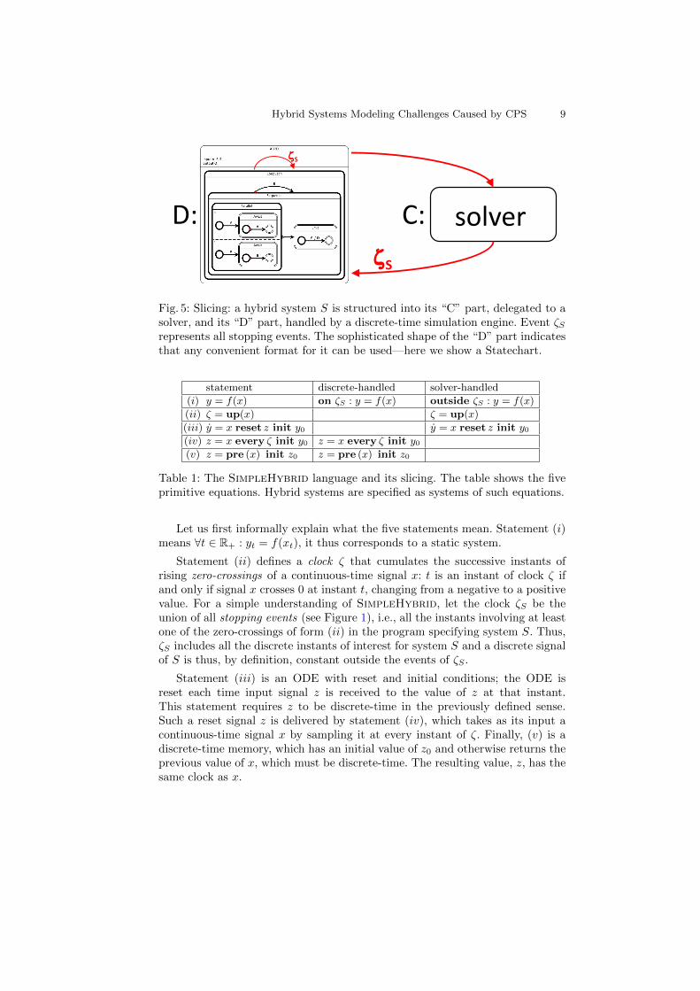
Figure 5 illustrates the concept of slicing we discussed in the previous section. Itdepicts the overall structure of the execution engine, in the form of a two stateautomaton that coordinates the solver and the management of mode changes.During the phase of positive duration and while the system is in the right-handstate, control is given to the solver handling the solver-handled dynamics. Thesephases alternate with discrete-handled phases, of zero duration, where control isgiven to the management of mode changes. As suggested by the inside shape ofthe corresponding macro-state, its structure can be arbitrarily complex and caninvolve several internal steps before terminating the handling of the changes.The solver is shown as a black-box, suggesting that it is monolithic. This, again,can be adjusted, as discussed later in Section 5.
Slicing requires structuring, at compile time, the hybrid system model intothe form shown in Figure 5. This requires some kind of static typing to allocatethe different parts of the program to the solver-handled and discrete-handledphases. Performing this is easy for simplistic languages, such as the SimpleHy-brid toy language shown in Table 1.
Hybrid Systems Modeling Challenges Caused by CPS 9
solver ζS
ζS
C: D:
Fig. 5: Slicing: a hybrid system S is structured into its “C” part, delegated to asolver, and its “D” part, handled by a discrete-time simulation engine. Event ζSrepresents all stopping events. The sophisticated shape of the “D” part indicatesthat any convenient format for it can be used—here we show a Statechart.
statement discrete-handled solver-handled
(i) y = f(x) on ζS : y = f(x) outside ζS : y = f(x)
(ii) ζ = up(x) ζ = up(x)
(iii) y = x reset z init y0 y = x reset z init y0(iv) z = x every ζ init y0 z = x every ζ init y0(v) z = pre (x) init z0 z = pre (x) init z0
Table 1: The SimpleHybrid language and its slicing. The table shows the fiveprimitive equations. Hybrid systems are specified as systems of such equations.
Let us first informally explain what the five statements mean. Statement (i)means ∀t ∈ R+ : yt = f(xt), it thus corresponds to a static system.
Statement (ii) defines a clock ζ that cumulates the successive instants ofrising zero-crossings of a continuous-time signal x: t is an instant of clock ζ ifand only if signal x crosses 0 at instant t, changing from a negative to a positivevalue. For a simple understanding of SimpleHybrid, let the clock ζS be theunion of all stopping events (see Figure 1), i.e., all the instants involving at leastone of the zero-crossings of form (ii) in the program specifying system S. Thus,ζS includes all the discrete instants of interest for system S and a discrete signalof S is thus, by definition, constant outside the events of ζS .
Statement (iii) is an ODE with reset and initial conditions; the ODE isreset each time input signal z is received to the value of z at that instant.This statement requires z to be discrete-time in the previously defined sense.Such a reset signal z is delivered by statement (iv), which takes as its input acontinuous-time signal x by sampling it at every instant of ζ. Finally, (v) is adiscrete-time memory, which has an initial value of z0 and otherwise returns theprevious value of x, which must be discrete-time. The resulting value, z, has thesame clock as x.

10 Benveniste et al.
In the above discussion we defined the qualifier “discrete-time” with refer-ence to the clock ζS of all stopping events in a system S. How does this comparewith the usual mathematical definition of this qualifier, namely: “a discrete clockis a subset of instants of R+ that is isomorphic to N as an order and divergesto infinity”? Unfortunately, no compiler can check this mathematical definition.However, if zero-crossing up(x) involves a smooth signal x, then the resultingsequence of instants of zero-crossing will be a discrete-time clock in the mathe-matical sense. Therefore, our definition of discrete-time based on ζS can be seenas a simple approximation to the mathematical one, based on syntactic criteria,i.e., one that can be checked by a compiler. With this definition of “discrete-time”, typing the signals in a SimpleHybrid program as either continuous ordiscrete becomes easy. Table 1 indicates how this typing is performed and howslicing follows from it. The detection of zero-crossings on a signal x, specifiedby statement (ii), is delegated to the solver. ODE (iii) is also handled by thesolver, but the reset events produced at some sub-clock of ζS by statement (iv)are handled by the discrete part. Needless to say, slicing is only tractable whencarefully anticipated by the language design. This difficulty was well illustratedby the nasty Simulink example of Figure 2.
3.2 Clarifying the small details with nonstandard analysis
y = 0 reset [1,−1] every up[x,−x] init − 1x = 0 reset [−1, 1, 1] every up[y,−y, z] init − 1z = 1 init − 1
Table 2: A spurious example with an unbounded cascade of resets.
Consider the example of Table 2, where the following shorthands have beenused to simplify the code. Expression “ reset . . . every up . . . init . . .” is ex-panded in an obvious way into core SimpleHybrid by introducing intermediatevariables. Next, “[x, y, z]” is a tuple collecting the given variables. When twotuples of the same cardinality are used in “ reset . . . every up . . .”, then resetsoccur using the first entry of the tuple each time the first entry of the up hasan event, or else using the second entry of the tuple each time the second entryof the up has an event, and so on.
In this program, interesting things occur at instant t = 1 when z crosses zero.This causes an immediate reset of x, from −1 to 1, which in turn causes a zero-crossing of x and thus a reset of y from −1 to 1, which then yields a zero-crossingfor y, thus causing a reset of x, from 1 to −1, which yields a zero-crossing of −x,thus causing a reset of y, from 1 to −1, which yields a zero-crossing of −y, thuscausing a reset of x, from −1 to 1, and so on, in a nonterminating loop.
This is another kind of spurious program we would like to reject since ititerates in an endless succession of resets. In addition, in explaining its execution,we have assume a particular interpretation of this unbounded cascade of causally

Hybrid Systems Modeling Challenges Caused by CPS 11
related resets in “zero-time”, which certainly requires being more precise aboutthe meaning of “up” than we have been so far.
In adopting super-dense time semantics [25] in the design of their hybridmodeler, E.A. Lee et al. [22,23] have made a first significant step. The problem isto provide a time index in which the continuous dynamics of ODEs and cascadesof resets in zero time can both be described. Just take T = R+ × N, totallyordered with the lexicographic order (s,m) < (t, n) if and only if either s < t, ors = t and m < n. For ODEs, the time index used is simply (t, 0) which identifieswith t. Successive cascades of events occurring at physical time t can be labeledby (t, 0), (t, 1), (t, 2) . . . This works well in most cases, but not always, as theexample of Table 2 shows.
In a previous paper [6], we proposed instead using nonstandard analysis asa semantic domain for hybrid systems. The interested reader is referred to theabove reference for a rapid introduction to nonstandard analysis, here, we onlydevelop enough to sketch its use in defining the semantics of hybrid systemsmodelers. For our purpose, we kindly ask the reader to accept the existence 14
of a time baseT = {n∂ | n ∈ ?N},
where ∂ is a nonstandard infinitesimal real number, and n is a nonstandard,possibly infinite, integer, such that:
(a) T inherits its total order from ?N;(b) Every subset of T which is bounded from below/above by a finite (nonstan-
dard) number has a unique minimal/maximal element;(c) T is dense in R+.
By (a) and (b), T looks discrete, and by (c) it looks continuous.15 In particular,it is legitimate to consider, for any t ∈ T, the instants just before and just aftert:16
•t = max{s ∈ T | s < t} or, equivalently, •(n∂) = (n− 1)∂t• = min{s ∈ T | s > t} or, equivalently, (n∂)• = (n+ 1)∂
which allows us to define, for a signal xt indexed by t ∈ T, its shifted versions•x and x•, by:
•xt =def x•t
x•t =def xt•(1)
By property (c), if signal xt, wheret ∈ T, is “smooth enough”, then it defines aunique standard signal st [x], indexed by R, and approximating x in the followingsense: if s ∈ R and t ∈ T are such that t−s is infinitesimal, then so is xt− st [x]s.When it exists, such a st [x] is unique, we call it the standardisation of x.
14 The skeptical reader can look for details in [6], or read some classics in nonstandardanalysis [34,13,14,24], or simply believe in it from the creationistic standpoint.
15 You have your cake and eat it too.16 In particular, any instant has a successor and a predecessor, which is not the case
for super-dense time R+ × N since (t, 0) has no unique predecessor.

12 Benveniste et al.
y
x
+1
−1∂ 2∂ 3∂ 4∂ 5∂ 6∂1
Table 3: Executions of the program of Table 2 starting from t = 1. Strictlyspeaking, only the values at instants 1, 1+∂, 1+2∂ . . . are defined. The piecewiselinear interpolation is only to make the drawing more readable.
Using these notations, we draw the behavior of the program of Table 2,starting from t = 1, in Figure 3, which we can describe by reformulating ourinformal explanation in terms of the nonstandard time basis. At t = 1, z crosseszero. This causes an event on up(z) at t = 1 + ∂, which causes an immediatereset of x, from −1 to 1. This then causes an event on up(x) at t = 1 + 2∂,which triggers an immediate reset of y, from −1 to 1. Now there is an event onup(y) at t = 1 + 3∂, which causes an immediate reset of x, from 1 to −1. Andso on, in the nonterminating loop shown in the figure.
Observe that the cascade of successive resets lasts for all t ∈ T, t ≥ 1. Inparticular, since T is dense in R+, time progresses to infinity as desired. Suchan example cannot be given a semantics in the super-dense time semantics withR+ × N as time index set. As another, more formal reason for rejecting thisprogram, we observe that it possesses no standardization. See [6] for suggestionson how to perform compile-time analyzes of this kind.
x = 0 reset 1 every up(z) init − 1z = 1 init − 1
Table 4: A simplification of the program of Table 2.
A variation of the program of Table 2 is shown in Table 4, where we removedy and the equation defining it and adapted the resets accordingly. While justa minor variation, this program is much less problematic as it only involves asingle cascade of two successive zero-crossings: one on z, which triggers anotherimmediately on x with no further effects.
The nonstandard semantics provides an elegant way to define the semantics ofboth programs and then to analyze them. For the first program, the nonstandardsemantics reveals an infinite cascade of resets that diverge to infinity and therebypreclude standardization. In contrast, the second example can be standardizedusing super-dense time to encode the two successive resets without any physicaltime passing. See [6] for further details.
The nonstandard semantics is not only useful for treating cascades of succes-sive zero-crossings, but also for encoding some kind of symbolic understandingof ODEs in a compiler. This is achieved by defining the nonstandard derivative

Hybrid Systems Modeling Challenges Caused by CPS 13
of a signal as follows, where ≈ means equality up to an infinitesimal:
x ≈ 1∂ (x− •x)
which yields, for the ODE
y = f(x, y) (2)
the nonstandard semantics:
y = •y + ∂ · f(x, y) (implicit Euler scheme)y = •y + ∂ · f(•x, •y) (explicit Euler scheme)
(3)
If f is smooth17 then the two schemes can be seen to be equivalent. Yet theexplicit scheme in (3) is always well defined for any f , whereas ODE (2) re-quires smoothness conditions for the existence and uniqueness of solutions. Themathematics of nonstandard analysis yields the following kind of result:
Pseudo-Theorem 1 Under smoothness conditions on f ensuring existence anduniqueness of the solutions of ODE (2), any of the two schemes of (3) possessesthe solution of (2) as its standardization, irrespective of the particular choice ofinfinitesimal time step ∂.
In [6], this result was extended to hybrid systems with finite cascades of modechanges. The target of the standardization is then the super-dense time R+×N,used to index the finite cascades.
statement nonstandard semantics
(i) y = f(x) y = f(x)
(ii) ζ = up(x) •ζ = [•x < 0] ∧ [x≥0]
(iii) y = x reset z init y0
y = if z present then zelse if not init then •y + ∂ · •xelse if init then y0
(iv) z = x every ζ init y0z = if ζ present then x
else if init then y0
(v) z = pre (x) init z0
x has discrete clock τz = {0, t1, t2, . . .}z has same clock as xztn = xtn−1 if n > 0, z0 given
Table 5: The SimpleHybrid kernel language and its nonstandard data-flowsemantics, using notation (1) and the explicit Euler scheme of (3).
Using this technique we can now formulate a full nonstandard semanticsfor the SimpleHybrid minilanguage, which is presented in Table 5 using the
17 Following the usage in mathematics, the vague term “smooth” is used here to denotespecific conditions that must be stated for the invoked property to hold. This termcan thus mean “continuous”, “Lipschitz”, etc., depending on the case.
14 Benveniste et al.
Model Σym
Gf (s)e
Relay Gp(s)y
−1
FilterGain
changer
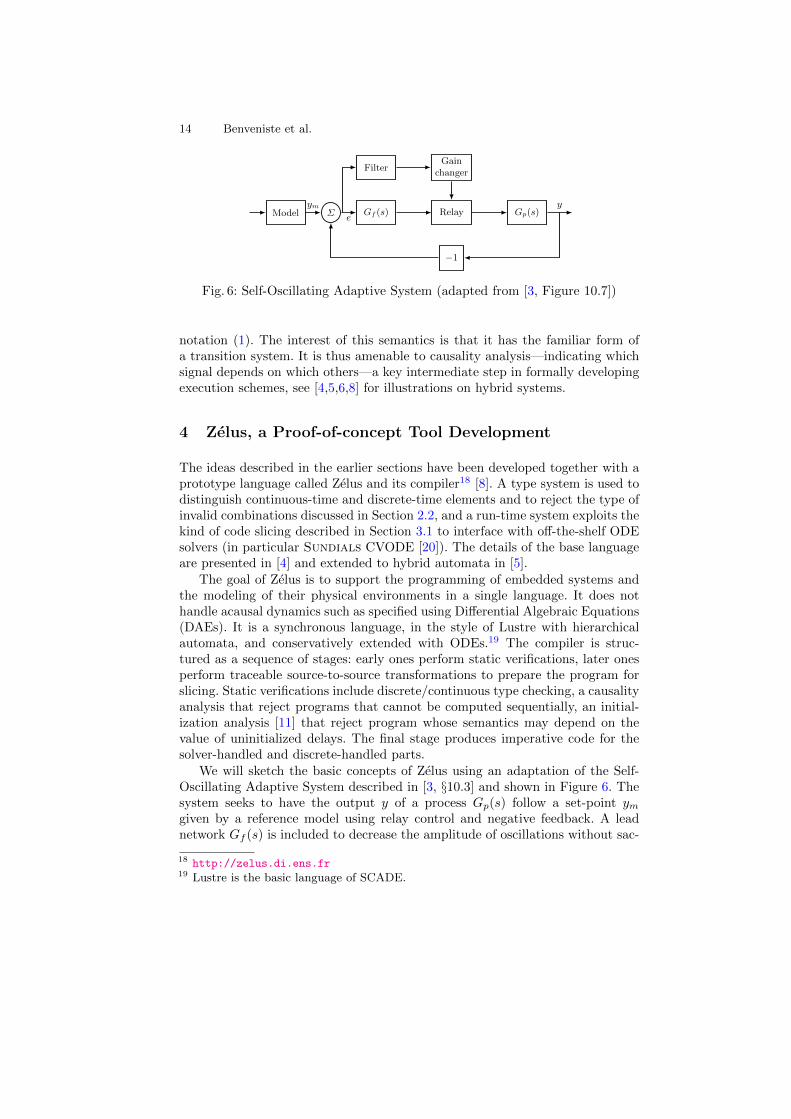
Fig. 6: Self-Oscillating Adaptive System (adapted from [3, Figure 10.7])
notation (1). The interest of this semantics is that it has the familiar form ofa transition system. It is thus amenable to causality analysis—indicating whichsignal depends on which others—a key intermediate step in formally developingexecution schemes, see [4,5,6,8] for illustrations on hybrid systems.
4 Zelus, a Proof-of-concept Tool Development
The ideas described in the earlier sections have been developed together with aprototype language called Zelus and its compiler18 [8]. A type system is used todistinguish continuous-time and discrete-time elements and to reject the type ofinvalid combinations discussed in Section 2.2, and a run-time system exploits thekind of code slicing described in Section 3.1 to interface with off-the-shelf ODEsolvers (in particular Sundials CVODE [20]). The details of the base languageare presented in [4] and extended to hybrid automata in [5].
The goal of Zelus is to support the programming of embedded systems andthe modeling of their physical environments in a single language. It does nothandle acausal dynamics such as specified using Differential Algebraic Equations(DAEs). It is a synchronous language, in the style of Lustre with hierarchicalautomata, and conservatively extended with ODEs.19 The compiler is struc-tured as a sequence of stages: early ones perform static verifications, later onesperform traceable source-to-source transformations to prepare the program forslicing. Static verifications include discrete/continuous type checking, a causalityanalysis that reject programs that cannot be computed sequentially, an initial-ization analysis [11] that reject program whose semantics may depend on thevalue of uninitialized delays. The final stage produces imperative code for thesolver-handled and discrete-handled parts.
We will sketch the basic concepts of Zelus using an adaptation of the Self-Oscillating Adaptive System described in [3, §10.3] and shown in Figure 6. Thesystem seeks to have the output y of a process Gp(s) follow a set-point ymgiven by a reference model using relay control and negative feedback. A leadnetwork Gf (s) is included to decrease the amplitude of oscillations without sac-
18 http://zelus.di.ens.fr19 Lustre is the basic language of SCADE.

Hybrid Systems Modeling Challenges Caused by CPS 15
rificing the response speed, and a gain changer is added to further improveperformance. This example mixes continuous behaviors and discontinuities.
let hybrid siso1o (a, b, c, d, u) = ywhererec der x = a ∗. x +. b ∗. u init 0.0and y = c ∗. x +. d ∗. u
let hybrid relay (d, e) = u whereautomaton| High →
do u = d until up(−. e) then Low| Low →
do u = −. d until up(e) then High
let hybrid gain changer (d1, d2, e l, e) = d whereautomaton| High →
local t in doder t = 1.0 init 0.0and d = d2 +. (d1 −. d2) ∗. exp(−.t)
until up(abs float e −. e l) then Normal| Normal →
dod = d1
until up(e l −. abs float e) then High
t = 1 init 0d = d2 + (d1 − d2) · e−t
d = d1
up(|e− el|) up(el − |e|)
Fig. 7: Zelus functions for the Self-Oscillating Adaptive System example
The transfer functions Gf (s) and Gp(s) are defined by instantiating basicsingle-input single-output functions, like the first-order version named siso1o
in Figure 7. The relay model is also shown in the figure, it is programmed inrelay as a hybrid automaton that changes state when the input e changes frompositive to negative or vice versa. The gain changer is also programmed as ahybrid automaton. The source code is shown in the function gain changer; agraphical representation is shown to its right. The state labeled High defines alocal variable t used to model an exponential reduction in d from a high gaind2 to a standard gain d1. The gain changer is readily composed with the relay:
u = relay (gain changer (0.5, 0.1, 0.1, e), g f e)
5 Perspectives: beyond ODE, beyond non-Zeno, andusing multi-solvers
5.1 Beyond ODEs
So far we have only discussed hybrid systems involving ODEs, as is the case forthe combination of Simulink/Stateflow.

16 Benveniste et al.
Yet ODEs are insufficient for modern hybrid system modeling. As a simpleexplanation, consider electrical circuits made by assembling predefined compo-nents, i.e., predefined smaller circuits. Composing such circuits is naturally ex-pressed using balance equations, namely the Ohm and Kirchhoff laws. In otherwords, it is not known in advance which wires will be inputs and which out-puts; this distinction is inherited from the context—the rest of the circuit—intowhich a component is placed. This need was first identified by H. Elmqvist inhis thesis [17]. It holds for a number of domains of physics—electrical, mechani-cal, hydraulic, etc. Balance equations then become the central paradigm, whichresults in the need to handle so-called Differential Algebraic Equations (DAE)
F (x(n), . . . , x, x, x, t) = 0 , (4)
where x(n) is the nth derivative of the Rk-valued state variable x, and F takesits values in Rp, expressing that it represents a system of p constraints involvingsignals and their successive derivatives. In addition, for hybrid systems, it is notenough to consider bilateral constraints of the form (4), one also needs unilateralconstraints (5) of the form
G(x(n), . . . , x, x, x, t) ≥ 0 . (5)
A unilateral constraint G represents a system of q constraints involving signalsand their successive derivatives. Any individual constraint is termed saturated ifequality holds for that constraint. The status saturated versus non saturated de-fines two modes. In one mode, the constraint has no effect locally on the variableswhereas it acts as an additional equality constraint when the constraint is satu-rated. Hence, when some unilateral constraint becomes saturated, then a modechange follows since the system dynamics involves a new equality constraint.When the system has q constraints, it may result in 2q different modes.
Causality synthesis is a new issue raised by DAE systems, where there is aneed to analyze systems to determine those signals defined by a set of equationsand constraints, i.e., which are the outputs, and those required from the context,i.e., which are the inputs. This is standard practice in, for instance, electriccircuits. Consider the following simple example, where everything is scalar, i.e.,R-valued:
x = f(x, u)0 = g(x)
(6)
In order to satisfy 0 = g(x), the “input” u must be constrained and thus classi-fying u as an input is questionable; as an analysis of causality would indicate.
Index reduction [10] is another new and more subtle issue that arises in DAEhybrid systems. Consider the two equations of system (6). At first sight, there areonly these two constraints. However, the need to consider dynamic behavior mayinduce so-called latent constraints [31], i.e., constraints that are not yet visible,but which can be made visible by, in this case, differentiating the constraintg(x) = 0 with respect to time:
0 = g′(x) · x = g′(x) · f(x, u) (7)

Hybrid Systems Modeling Challenges Caused by CPS 17
where g′ is the derivative of g with respect to x. Note that (7) is not redundantwith (6), rather it is a consequence of it, through differentiation. Also, (7) makesexplicit that u is indeed constrained.
It is interesting to reconsider this reasoning using nonstandard semantics (3)for ODEs, with the implicit Euler scheme. This gives, for (6):
x− •x = ∂ · f(x, u)0 = g(x)
(8)
Now, since (8) is time-invariant, the second constraint also holds at the previousinstant, thus (8) is indeed equivalent to
x− •x = ∂ · f(x, u)0 = g(x)0 = g(•x)
(9)
The newly added third constraint is not redundant with the other two, nordoes it involve any new variables (•x was already there). Shifting this additionalconstraint further into to the past yields 0 = g(••x), thereby adding one moreequation but with one more variable ••x. So, 0 = g(•x) is the missing latentconstraint. Yet it was exhibited in the discrete time form of the nonstandardsemantics. The following execution scheme goes together with (9):
– at initialization when t = 0:1. we evaluate •x using the third equation;2. we evaluate x using the second equation;3. we evaluate u using the first equation.
– when t > 0:1. we know from instant •t that 0 = g(•x) holds at the current instant t;2. we evaluate x using the second equation;3. we evaluate u using the first equation.
Making latent constraints explicit, referred to as index reduction, requires con-sidering a bipartite graph whose two types of vertices are the variables of theprogram and the equations of the program. An edge exists between a variableand an equation when the variable occurs in that equation. For DAEs in hy-brid systems, index reduction is mode dependent, and each edge of the bipartitegraph must be labeled with a predicate characterizing the modes in which it ap-plies. This type of analysis turns out to be very similar to the mode-dependentcausality analyzes developed for the compilation of synchronous languages, andespecially that of Signal [7].
5.2 Beyond non-Zeno
In the analysis of hybrid systems, the accumulation of an unbounded numberof mode changes in finite time, so-called Zeno behavior, is viewed by computerscientists as problematic. It is indeed true that a computer control system should
18 Benveniste et al.
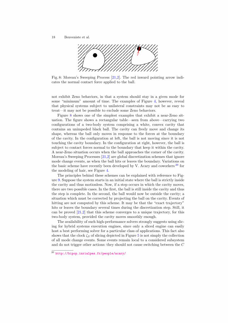
Fig. 8: Moreau’s Sweeping Process [21,2]. The red inward pointing arrow indi-cates the normal contact force applied to the ball.
not exhibit Zeno behaviors, in that a system should stay in a given mode forsome “minimum” amount of time. The examples of Figure 4, however, revealthat physical systems subject to unilateral constraints may not be as easy totreat—it may not be possible to exclude some Zeno behaviors.
Figure 8 shows one of the simplest examples that exhibit a near-Zeno sit-uation. The figure shows a rectangular table—seen from above—carrying twoconfigurations of a two-body system comprising a white, convex cavity thatcontains an unimpeded black ball. The cavity can freely move and change itsshape, whereas the ball only moves in response to the forces at the boundaryof the cavity. In the configuration at left, the ball is not moving since it is nottouching the cavity boundary. In the configuration at right, however, the ball issubject to contact forces normal to the boundary that keep it within the cavity.A near-Zeno situation occurs when the ball approaches the corner of the cavity.Moreau’s Sweeping Processes [21,2] are global discretization schemes that ignoremode change events, as when the ball hits or leaves the boundary. Variations onthe basic scheme have recently been developed by V. Acary and coworkers 20 forthe modeling of hair, see Figure 4.
The principles behind these schemes can be explained with reference to Fig-ure 9. Suppose the system starts in an initial state where the ball is strictly insidethe cavity and thus motionless. Now, if a step occurs in which the cavity moves,there are two possible cases. In the first, the ball is still inside the cavity and thusthe step is complete. In the second, the ball would now be outside the cavity; asituation which must be corrected by projecting the ball on the cavity. Events ofhitting are not computed by this scheme. It may be that the “exact trajectory”hits or leaves the boundary several times during the discretization step. Still, itcan be proved [21,2] that this scheme converges to a unique trajectory, for thistwo-body system, provided the cavity moves smoothly enough.
The availability of such high-performance solvers strongly suggests using slic-ing for hybrid systems execution engines, since only a sliced engine can easilyhost a best performing solver for a particular class of applications. This fact alsoshows that the clock ζS of slicing depicted in Figure 5 is not simply the collectionof all mode change events. Some events remain local to a considered subsystemand do not trigger other actions: they should not cause switching between the C
20 http://bipop.inrialpes.fr/people/acary/

Hybrid Systems Modeling Challenges Caused by CPS 19
Fig. 9: Moreau’s Sweeping Process [21,2]. Left: original position. Top right: firstcase, shifting the cavity from dashed to solid. Bottom right: second case, shiftingthe cavity from dashed to solid; projection is needed.
and D modes. On the other hand, when such events are used to synchronize ex-ternal actions, they must cause switching from the C mode to the D mode. Thediscrete/continuous typing system must be adjusted to take this into account.
5.3 Using multi-solvers
Existing hybrid systems modelers use a single global solver. Thus all parts of asystem share the same discretization scheme. Consider a situation in which twosubsystems do not interact at the specification level, i.e., their respective systemsof equations do not share any variables. Nevertheless, when they are simulatedwith a single solver, the time scales of one system can influence the executionof the other since both share the same discretization scheme. In such a trivialcase, an easy solution consists in using two independent solvers running asyn-chronously, one for each subsystem, and only synchronizing to plot the results.Less trivial situations can be handled in a similar way, e.g., when the influencebetween two subsystems is unidirectional—S1 influences S2 but not conversely.Compile time analysis can identify such situations. Multi-solver simulation mayalso be considered when bi-directional interactions only occur at some discreteevents, or when the time scales of different systems are drastically separated.Both cases, however, result in approximations, not just a restructuring of exe-cutions. This is beyond what a compiler can do at the present time.
6 Conclusion
Modeling tools for hybrid systems are widely used in engineering. They are, ofcourse, central to the design of CPS. Despite the wide use of such tools, theystill face some embarrassing problems, sometimes resulting in spurious behaviors

20 Benveniste et al.
for some models. Also, for the tools supporting DAEs, state explosion remainsa problem when the number of modes in the hybrid systems becomes large.
We have reviewed some unnoticed challenges related to hybrid systems mod-eling. We first advocated an effort in theory, very much like the effort that wasperformed in the past by the community of synchronous languages. We believethat nonstandard semantics has many advantages for this task. Then, we ob-served that the community of numerical analysis is still making huge progressin dedicated solvers for specific application areas. This, we believe, speaks infavor of a modular approach to the design of hybrid systems modelers, in whichDAE/ODE solving is delegated to the best available tools, and the handlingof discrete events of mode changes is coordinated by a new generation of syn-chronous language engines, able to manage the new kinds of causality analysisneeded not just for functions but also for constraints.
References
1. Vincent Acary. Higher order event capturing time–stepping schemes for nonsmoothmultibody systems with unilateral constraints and impacts. Applied NumericalMathematics, 62:1259–1275, 2012.
2. Vincent Acary and Bernard Brogliato. Numerical Methods for Nonsmooth Dynam-ical Systems: Applications in Mechanics and Electronics. Springer Verlag, 2008.
3. Karl J. Astom and Bjorn Wittenmark. Adaptive Control. Dover Publications, 2ndedition, 2008.
4. Albert Benveniste, Timothy Bourke, Benoıt Caillaud, and Marc Pouzet. Divideand recycle: types and compilation for a hybrid synchronous language. In JanVitek and Bjorn De Sutter, editors, LCTES, pages 61–70. ACM, 2011.
5. Albert Benveniste, Timothy Bourke, Benoıt Caillaud, and Marc Pouzet. A hybridsynchronous language with hierarchical automata: static typing and translation tosynchronous code. In Samarjit Chakraborty, Ahmed Jerraya, Sanjoy K. Baruah,and Sebastian Fischmeister, editors, EMSOFT, pages 137–148. ACM, 2011.
6. Albert Benveniste, Timothy Bourke, Benoıt Caillaud, and Marc Pouzet. Non-standard semantics of hybrid systems modelers. J. Comput. Syst. Sci., 78(3):877–910, 2012.
7. Albert Benveniste, Paul Caspi, Stephen A. Edwards, Nicolas Halbwachs, Paul LeGuernic, and Robert de Simone. The synchronous languages 12 years later. Pro-ceedings of the IEEE, 91(1):64–83, 2003.
8. Timothy Bourke and Marc Pouzet. Zelus: a synchronous language with ODEs. InCalin Belta and Franjo Ivancic, editors, HSCC, pages 113–118. ACM, 2013.
9. Luca P. Carloni, Fernando De Bernardinis, Alberto L. Sangiovanni-Vincentelli, andMarco Sgroi. Platform-based and derivative design. In Richard Zurawski, editor,The Industrial Information Technology Handbook, pages 1–15. CRC Press, 2005.
10. Francois E. Cellier and Ernesto Kofman. Continuous System Simulation. SpringerVerlag, 2006.
11. Jean-Louis Colaco and Marc Pouzet. Type-based Initialization Analysis of a Syn-chronous Data-flow Language. International Journal on Software Tools for Tech-nology Transfer (STTT), 6(3):245–255, August 2004.
12. Patricia Derler, Edward A. Lee, and Alberto L. Sangiovanni-Vincentelli. Modelingcyber-physical systems. Proceedings of the IEEE, 100(1):13–28, 2012.

Hybrid Systems Modeling Challenges Caused by CPS 21
13. Francine Diener and Georges Reeb. Analyse non standard. Hermann, 1989.14. Nigel Cutland (ed.). Nonstandard analysis and its applications. Cambridge Univ.
Press, 1988.15. John C. Eidson, Edward A. Lee, Slobodan Matic, Sanjit A. Seshia, and Jia Zou.
Distributed real-time software for cyber-physical systems. Proceedings of the IEEE,100(1):45–59, 2012.
16. Johan Eker, Jorn W. Janneck, Edward A. Lee, Jie Liu, Xiaojun Liu, Jozsef Ludvig,Stephen Neuendorffer, Sonia R. Sachs, and Yuhong Xiong. Taming heterogeneity- the Ptolemy approach. Proceedings of the IEEE, 91(1):127–144, 2003.
17. Hilding Elmqvist. A Structured Model Language for Large Continuous Systems.PhD thesis, Department of Automatic Control, Lund University, Sweden, May1978.
18. Hilding Elmqvist, Fabien Gaucher, Sven Erik Mattsson, and Dupont Fran cois.State machines in Modelica. In Otter and Zimmer [30], pages 37–46.
19. Peter Fritzson. Principles of Object-Oriented Modeling and Simulation with Mod-elica 2.1. Wiley, 2004. ISBN 0-471-471631.
20. Alan C. Hindmarsh, Peter N. Brown, Keith E. Grant, Steven L. Lee, Radu Serban,Dan E. Shumaker, and Carol S. Woodward. SUNDIALS: Suite of nonlinear anddifferential/algebraic equation solvers. ACM Trans. Math. Soft., 31(3):363–396,September 2005.
21. Markus Kunze and Manuel D.P. Monteiro Marques. An introduction to moreau’ssweeping process. In Bernard Brogliato, editor, Impacts in Mechanical Systems -Analysis and Modelling, pages 1–60. Springer-Verlag Lecture Notes in Physics 551,2000.
22. Edward A. Lee and Haiyang Zheng. Operational semantics of hybrid systems. InHSCC, pages 25–53, 2005.
23. Edward A. Lee and Haiyang Zheng. Leveraging synchronous language principlesfor heterogeneous modeling and design of embedded systems. In EMSOFT, pages114–123, 2007.
24. Tom Lindstrøm. An invitation to nonstandard analysis. In N.J. Cutland, editor,Nonstandard Analysis and its Applications, pages 1–105. Cambridge Univ. Press,1988.
25. Oded Maler, Zohar Manna, and Amir Pnueli. From timed to hybrid systems. InREX Workshop, pages 447–484, 1991.
26. The Mathworks, Natick, MA, U.S.A. Simulink: Developing S-Functions, r2013aedition, March 2013. Release 2013a.
27. The Mathworks, Natick, MA, U.S.A. Simulink: User’s Guide, r2013a edition,March 2013. Release 2013a.
28. S.E. Mattsson, H. Elmqvist, and M. Otter. Physical system modeling with Mod-elica. Control Engineering Practice, 6:501–510, 1998.
29. Martin Otter, Hilding Elmqvist, and Sven Erik Mattsson. Hybrid modeling inModelica based on the synchronous data flow principle. In Otter and Zimmer [30],pages 1–7.
30. Martin Otter and Dirk Zimmer, editors. Proc. of the Int. Modelica Conference,Munich, Germany, September 2012. Modelica Association.
31. Constantinos C. Pantelides. The consistent initialization of differential-algebraicsystems. SIAM J. Sci. Stat. Comput., 9(2):213–231, 1988.
32. Alessandro Pinto, Alvise Bonivento, Alberto L. Sangiovanni-Vincentelli, RobertoPasserone, and Marco Sgroi. System level design paradigms: Platform-based de-sign and communication synthesis. ACM Trans. Design Autom. Electr. Syst.,11(3):537–563, 2006.

22 Benveniste et al.
33. Radha Poovendran, Krishna Sampigethaya, Sandeep K. S. Gupta, Insup Lee,K. Venkatesh Prasad, David Corman, and James L. Paunicka. Special issue oncyber-physical systems [scanning the issue]. Proceedings of the IEEE, 100(1):6–12,2012.
34. Abraham Robinson. Non-Standard Analysis. Princeton Landmarks in Mathemat-ics, 1996. ISBN 0-691-04490-2.
35. Alberto L. Sangiovanni-Vincentelli and Grant Martin. Platform-based design andsoftware design methodology for embedded systems. IEEE Design & Test of Com-puters, 18(6):23–33, 2001.