hydac hydraulic motors mpf / a / v / r 200 · ll s25 splined shaft ansi b92.1 16/32 – 15 teeth...
TRANSCRIPT

EN
2.9
14.0
/05.
18
HYDACHydraulic MotorsMPF / A / V / R 200

2
EN
2.9
14.0
/05.
18
3
EN
2.9
14.0
/05.
18
HYDRAULIC MOTORSMPF200 / MPA200 / MPV200 / MPR200
Ordering code 1.1 MPF200–fixeddisplacementmotor 4 1.2 MPA200–manuallyadjustablefixeddisplacenemtmotor 6 1.3 MPV200–variabledisplacementmotor 8 1.4 MPR200–regulatingmotor 12
Technical information 2.1 Specifications 15 2.2 Flangesandshafts 16 2.2.1 MPF200 16 2.2.2 MPA200 16 2.2.3 MPV200 17 2.2.4 MPR200 18 2.3 MPA200/MPV200withthroughdriveoption 20 2.3.1 MPA200 20 2.3.2 MPV200 20 2.4 MPA200/MPV200withcouplingflange(optionF40) 21 2.5 Seals 22 2.6 Filtration 22 2.7 Hydraulicfluids 22 2.8 Temperaturerange 22 2.9 Viscosityrange 22 2.10 Installationinstructions 23 2.11 Pipingexample 24 Motor variants 3.1 Functionoverview 25 3.2 MPF200 26 3.3 MPA200 26 3.4 MPV200 27 3.4.1 MPV200H1/H4andE1(E1F)/E4(E4F)/E6(E6F)variableadjustable 27 3.4.2 MPV200H2andE2(E2F)two-position 31 3.4.3 MPV200EH1P,EH1P-CAvariableadjustablewithpressureoverride 33 3.4.4 MPV200Ttandemmotor 35 3.5 MPR200 36 3.5.1 MPR200withVmaxoverridecontrol 37 3.5.2 MPR200withpressurecontrolsideselection 38
Accessories 4.1 Purgereliefvalveoptions 39 4.2 Highpressurereliefvalve(onlyforMPF200/MPR200) 40 4.3 Speedsensor 42 4.4 Crossoverreliefvalveblock 42
Dimensions 5.1 MPF200 43 5.2 MPA200 45 5.3 MPV200 47 5.4 MPR200 50 5.5 Connections 52

4
EN
2.9
14.0
/05.
18
MPF200 - 055 N - 000 N10 N0 U07 - M ...
TypeMPF200
Sizes
028
035
055
063
075
085
105
135
Sizel 028 28cm³/rev.l 035 35cm³/rev.l 055 55cm³/revl 063 63cm³/rev.l 075 75cm³/rev.l 085 85cm³/rev.l 105 105cm³/rev.l 135 135cm³/rev.
Direction of rotationl l l l l l l l N clockwiserotation/
anti-clockwiserotation
High-pressure valves onrequestl l l l l l l l B00 Sealingplugl l l l l l l l 000 withoutHigh-pressurevalve
Purge relief valvel l l l l l l l N10 10barstandardflowl l l l l l l l N14 14barstandardflowl l l l l l l l R10 10barreducedflowl l l l l l l l R14 14barreducedflowl l l l l l l l H10 10barincreasedflowl l l l l l l l Q06 Flowcontrolled6l/minl l l l l l l l B00 Sealingplug(*7B)l l l l l l l l 000 withoutpurgereliefvalve
Purge shuttle valvesl l l l l l l l N0 Standardl l l l l l l l D0 Dampedl l l l l l l l B0 Blocked(*6B)l l l l l l l l 00 withoutpurgeshuttlevalve
Speed sensor in housingl l U07 7pulsesperrotation
l l U09 9pulsesperrotationl l l l l l l l 000 Withoutspeedsensor
Portingl l l l l l l M MetricISO6149-1l l l l l l l l D DIN3852-1(ISO9974-1)
ORDERING CODE 1.1 MPF200 – Fixed displacement motor
>>
>>

5
EN
2.9
14.0
/05.
18
... S0 S32 - R00 - 000 - R00 - N
Sizes
028
035
055
063
075
085
105
135
Mounting flangel l l l l l l l S0 SAEJ744Standard(SAE2-holeflange)
l l l S4 SAEJ744(SAE4-holeflange)l P0 Installationflange
Output shaftl l S25 SplinedshaftANSIB92.116/32–15teeth(SAEJ744B-B)
l l l l l S32 SplinedshaftANSIB92.112/24–14teeth(SAEJ744C)l S44 SplinedshaftANSIB92.18/16–13teeth(SAEJ744D&E)
l l l l l T21 SplinedshaftANSIB92.116/32–21teethl T23 SplinedshaftANSIB92.116/32–23teethl T27 SplinedshaftANSIB92.116/32–27teeth
l l l F40 Couplingflangesize4(*SF0)/(*11F)
Ports and through drivel l l l l l l l R00 Radialports/nothroughdrive
l l l l l l L00 Axialports/nothroughdrive
Attachment partsl l l l l l l l 000 Withoutattachmentparts
Surface protection / paintl l l l l l l l R00 Rustprotectionoil(standard)l l l l l l l l P01 primed,RAL3009(red)l l l l l l l l P03 primed,bluel l l l l l l l P06 primed,grey(RAL7043)l l l l l l l l V03 Primed+painted,RAL9005(black)l l l l l l l l V07 Primed+painted,RAL7015(grey)
Special requirementsl l l l l l l l N nospecialrequirements(standard)▲ ▲ ▲ ▲ ▲ ▲ ▲ ▲ C Specialrequirements
(*6B) withblindpluginsteadofpressurereliefvalve(*7B) onlywithblockedshuttlevalve(*11F) sizes/shafts:55/T21,63/T21,75/T21,85/T23;105/T23,135/T27(*SF0) acc.toSAEJ1946TypeA(120/75/101.5/8xM10)
l availableoption
preferredoption
optiononrequest
▲ separatespecificationrequired
6
EN
2.9
14.0
/05.
18
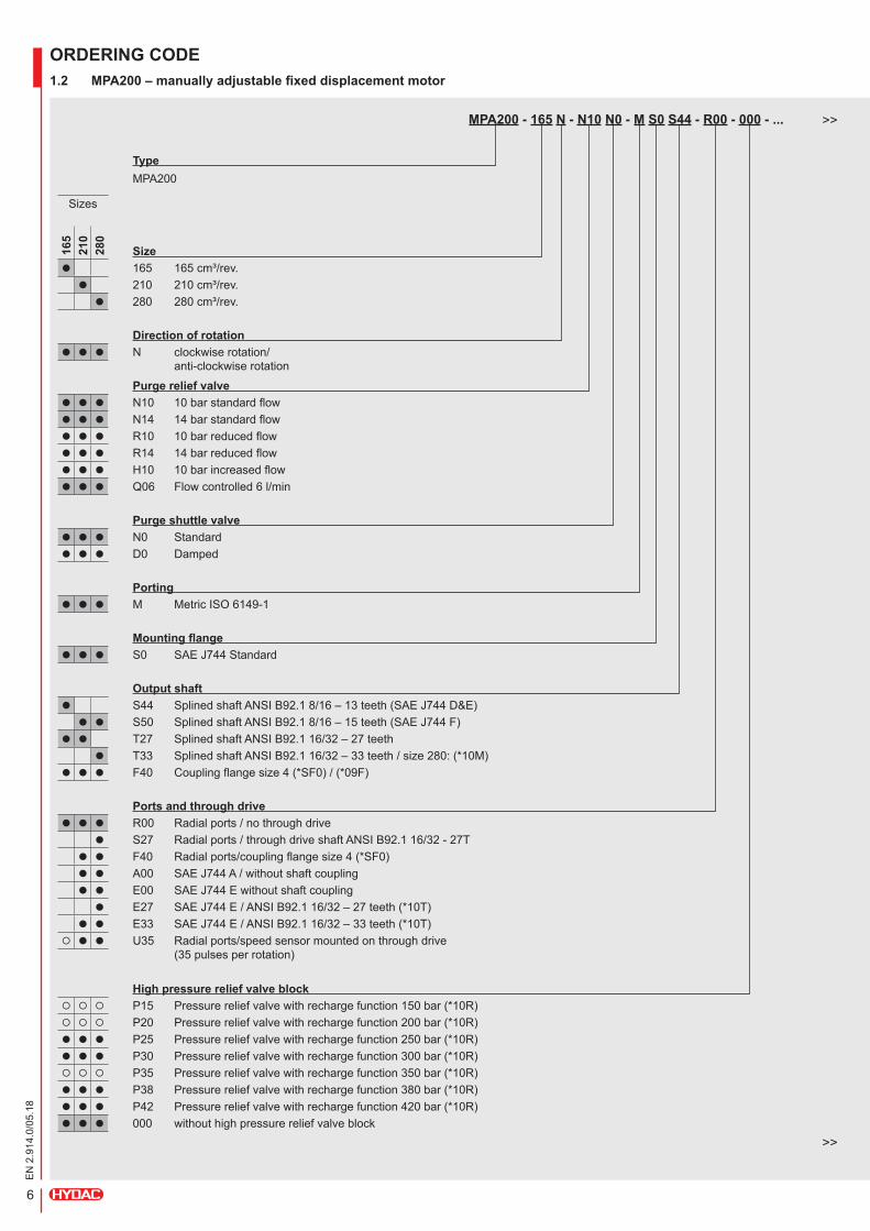
MPA200 - 165 N - N10 N0 - M S0 S44 - R00 - 000 - ...
TypeMPA200
Sizes
165
210
280
Sizel 165 165cm³/rev.l 210 210cm³/rev.l 280 280cm³/rev.
Direction of rotationl l l N clockwiserotation/
anti-clockwiserotation
Purge relief valvel l l N10 10barstandardflowl l l N14 14barstandardflowl l l R10 10barreducedflowl l l R14 14barreducedflowl l l H10 10barincreasedflowl l l Q06 Flowcontrolled6l/min
Purge shuttle valvel l l N0 Standardl l l D0 Damped
Portingl l l M MetricISO6149-1
Mounting flangel l l S0 SAEJ744Standard
Output shaftl S44 SplinedshaftANSIB92.18/16–13teeth(SAEJ744D&E)l l S50 SplinedshaftANSIB92.18/16–15teeth(SAEJ744F)
l l T27 SplinedshaftANSIB92.116/32–27teethl T33 SplinedshaftANSIB92.116/32–33teeth/size280:(*10M)
l l l F40 Couplingflangesize4(*SF0)/(*09F)
Ports and through drivel l l R00 Radialports/nothroughdrive
l S27 Radialports/throughdriveshaftANSIB92.116/32-27Tl l F40 Radialports/couplingflangesize4(*SF0)l l A00 SAEJ744A/withoutshaftcouplingl l E00 SAEJ744Ewithoutshaftcouplingl E27 SAEJ744E/ANSIB92.116/32–27teeth(*10T)
l l E33 SAEJ744E/ANSIB92.116/32–33teeth(*10T) l l U35 Radialports/speedsensormountedonthroughdrive
(35pulsesperrotation)
High pressure relief valve block P15 Pressurereliefvalvewithrechargefunction150bar(*10R) P20 Pressurereliefvalvewithrechargefunction200bar(*10R)l l l P25 Pressurereliefvalvewithrechargefunction250bar(*10R)l l l P30 Pressurereliefvalvewithrechargefunction300bar(*10R) P35 Pressurereliefvalvewithrechargefunction350bar(*10R)l l l P38 Pressurereliefvalvewithrechargefunction380bar(*10R)l l l P42 Pressurereliefvalvewithrechargefunction420bar(*10R)l l l 000 withouthighpressurereliefvalveblock
ORDERING CODE 1.2 MPA200 – manually adjustable fixed displacement motor
>>
>>
7
EN
2.9
14.0
/05.
18
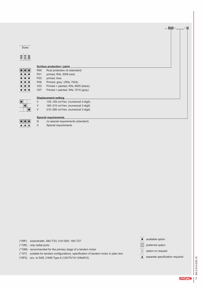
... R00 - - N
Sizes
165
210
280
Surface protection / paintl l l R00 Rustprotectionoil(standard)l l l P01 primed,RAL3009(red)l l l P03 primed,bluel l l P06 Primed,grey/(RAL7043)l l l V03 Primed+painted,RAL9005(black)l l l V07 Primed+painted,RAL7015(grey)
Displacement settingl V 135–165cm³/rev.(numerical3-digit)l V 165–210cm³/rev.(numerical3-digit)l V 210–280cm³/rev.(numerical3-digit)
Special requirementsl l l N nospecialrequirements(standard)▲ ▲ ▲ C Specialrequirements
(*09F) sizes/shafts:280/T33;210/S50;165/T27(*10R) onlyradialports(*10M) recommendedfortheprimarystageofatandemmotor(*10T) suitablefortandemconfigurations,specificationoftandemmotorinplaintext(*SF0) acc.toSAEJ1946TypeA(120/75/101.5/8xM10)
l availableoption
preferredoption
optiononrequest
▲ separatespecificationrequired

8
EN
2.9
14.0
/05.
18
MPV200 - 055 N - H100 HF5 00 ...
TypeMPV200
Sizes
055
075
105
135
165
210
280
Sizel 055 55cm³/rev. ( 28– 55cm³/rev.max.adjustingrange)l 075 75cm³/rev. ( 55– 75cm³/rev.max.adjustingrange)l 105 105cm³/rev. ( 75–105cm³/rev.max.adjustingrange)l 135 135cm³/rev. (105–135cm³/rev.max.adjustingrange)l 165 165cm³/rev. (135–165cm³/rev.max.adjustingrange)l 210 210cm³/rev. (165–210cm³/rev.max.adjustingrange)l 280 280cm³/rev. (210–280cm³/rev.max.adjustingrange)
Direction of rotationl l l l l l l N clockwiserotation/
anti-clockwiserotation
Control optionsl l l l l l l H100 H1hydraulicallyproportional/standard/Vmax->Vmin(Vmin=0.3*Vmax)l l l H200 H2hydraulicallyswitching/Vmax->Vmin(Vmin=0(*7S))
l l l l l l H400 H4H-prop/min.(Vmin)=0/Vmax->Vmin(~0)l l l l l l l E100 E1electricallyproportional/standard/Vmax->Vmin(Vmin=0.3*Vmax)(*7S)l l l l l l l E200 E2electricallyswitching/Vmax->Vmin(Vmin=0(*7S))l l l l l l l E400 E4min.(Vmin)=0(*7S)l l l l l l E600 E6electricallyproportional/Vmin->Vmax;Vmin=0(*7R)l l E1F0 E1Felectricallyproportional/side-mounted/Vmax->Vmin(*7R)
E2F0 E2Felectricallyswitching/min.(Vmin)=0/side-mounted(*7R)l l l E4F0 E4Felectricallyproportional/min.(Vmin)=0/side-mounted/Vmax->Vmin(~0)(*7R)l l E6F0 E6Felectricallyproportionalinverse/min.(Vmin)=0/side-mounted(*7R)l l l l H1P0 EH1Phydr.prop./withmax.closedlooppressurecontrol/withelectricalmastercontrol(*5MR)/(*7S)l l l l l H1PC EH1P-CAhydr.prop./speed-dependent/withmax.closedlooppressurecontrol/
withelectricalmastercontrol(*5C)
Control pressure rangel l l l l l HA0 4.0bar(H4)l l l l l l l HF0 7.0bar(H1;EH1P)l l l l l l l HF5 7.5bar(H1;EH1P;H1-CA;EH1P-CA)l l l l l l l HH0 8.0bar(H1;EH1P)l l l l l l l HH5 8.5bar(H1;EH1P)l l l l l l l HK0 9.0bar(H1;EH1P)l l l l l l l HK5 9.5bar(H1;H4;EH1P)l l l l l l l 000 Notapplicable(E1(F);E4(F);E6(F))
Control solenoidsl l l l l l l A1 AMP / 12 Vl l l l l l l A2 AMP / 24 Vl l l l l l l H1 DIN / 12 Vl l l l l l l H2 DIN / 24 Vl l l l l l l D1 Deutsch/12Vl l l l l l l D2 Deutsch/24Vl l l l l l l 00 Notapplicable(H1;H1-CA;H2;H4)
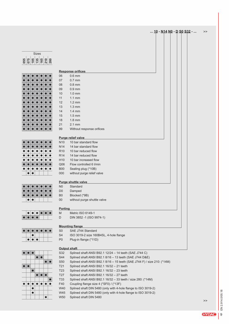
ORDERING CODE 1.3 MPV200 – variable displacement motor
>>
>>
9
EN
2.9
14.0
/05.
18
... 10 - N14 N0 - D S0 S32 - ...
Sizes
055
075
105
135
165
210
280
Response orificesl l l l l l l 06 0.6mml l l l l l l 07 0.7mml l l l l l l 08 0.8mml l l l l l l 09 0.9mml l l l l l l 10 1.0mml l l l l l l 11 1.1mml l l l l l l 12 1.2mml l l l l l l 13 1.3mml l l l l l l 14 1.4mml l l l l l l 15 1.5mml l l l l l l 18 1.8mml l l l l l l 21 2.1mml l l l l l l 99 Withoutresponseorifices
Purge relief valvel l l l l l l N10 10barstandardflowl l l l l l l N14 14barstandardflowl l l l l l l R10 10barreducedflowl l l l l l l R14 14barreducedflowl l l l l l l H10 10barincreasedflowl l l l l l l Q06 Flowcontrolled6l/minl l l l l l l B00 Sealingplug(*10B)l l 000 withoutpurgereliefvalve
Purge shuttle valvel l l l l l l N0 Standardl l l l l l l D0 Dampedl l l l l l l B0 Blocked(*9B)l l 00 withoutpurgeshuttlevalve
Portingl l l l l l M MetricISO6149-1
l l l l D DIN3852-1(ISO9974-1)
Mounting flangel l l l l l l S0 SAEJ744Standard
l S4 ISO3019-2size160B4SL,4-holeflangel l l P0 Plug-inflange(*11D)
Output shaftl l l S32 SplinedshaftANSIB92.112/24–14teeth(SAEJ744C)
l l S44 SplinedshaftANSIB92.18/16–13teeth(SAEJ744D&E)l l S50 SplinedshaftANSIB92.18/16–15teeth(SAEJ744F)/size210:(*14M)
l l T21 SplinedshaftANSIB92.116/32–21teethl T23 SplinedshaftANSIB92.116/32–23teethl l l T27 SplinedshaftANSIB92.116/32–27teeth
l T33 SplinedshaftANSIB92.116/32–33teeth/size280:(*14M)l l l l l l l F40 Couplingflangesize4(*SF0)/(*13F)
l W40 SplinedshaftDIN5480(onlywith4-holeflangetoISO3019-2)l W45 SplinedshaftDIN5480(onlywith4-holeflangetoISO3019-2)
l W50 SplinedshaftDIN5480>>
>>

10
EN
2.9
14.0
/05.
18
... R00 - 000 - R00 - / 999 - ...
Sizes
055
075
105
135
165
210
280
Ports and through drivel l l l l l l R00 Radialports/nothroughdrive
l l l L00 Axialports/nothroughdrive S19 Radialports/throughdriveshaftANSIB92.116/32–19teeth S21 Radialports/throughdriveshaftANSIB92.116/32–21teeth S22 Radialports/throughdriveshaftANSIB92.116/32–22teethl S24 Radialports/throughdriveshaftANSIB92.116/32–24teethl S27 Radialports/throughdriveshaftANSIB92.116/32–27teeth
l l l l F40 Radialports/couplingflangesize4(*SF0)l l A00 SAEJ744A/tandemflangel l E00 SAEJ744Enocouplingsleeve(*5H)/(*5MR)l l E27 SAEJ744E/ANSIB92.116/32–27teeth(*5H)/(*5MR)/(*14T)l E33 SAEJ744E/ANSIB92.116/32–33teeth(*5H)/(*5MR)/(*14T)
l l l l l l l U35 Radialports/speedsensormountedonthroughdrive (35pulsesperrotation)
High pressure relief valve l P15 Pressurereliefvalve150bar(*14R) P20 Pressurereliefvalve200bar(*14R)l l l P25 Pressurereliefvalve250bar(*14R)l l l P30 Pressurereliefvalve300bar(*14R) P35 Pressurereliefvalve350bar(*14R)l l l P38 Pressurereliefvalve380bar(*14R)l l l P42 Pressurereliefvalve420bar(*14R)
l l l l l l l 000 withouthighpressurereliefvalve
Surface protection / paintl l l l l l l R00 Rustprotectionoil(standard)l l l l l l l P01 primed,RAL3009(red)l l l l l l l P03 primed,bluel l l l l l l P06 primed,grey(RAL7043)l l l l l l l V03 Primed+painted,RAL9005(black)l l l l l l l V07 Primed+painted,RAL7015(grey)
Min. displacement settingl Vmin 000–035cm³/rev.(numerical3-digit)(*5V0)l Vmin 016–035cm³/rev.(numerical3-digit)(*5V1)l Vmin 000–055cm³/rev.(numerical3-digit)(*5V0)l Vmin 022–055cm³/rev.(numerical3-digit)(*5V1)l Vmin 000–075cm³/rev.(numerical3-digit)(*5V0)l Vmin 031–075cm³/rev.(numerical3-digit)(*5V1)l Vmin 000–088cm³/rev.(numerical3-digit)(*5V0)l Vmin 040–088cm³/rev.(numerical3-digit)(*5V1)l Vmin 000–108cm³/rev.(numerical3-digit)(*5V0)l Vmin 045–108cm³/rev.(numerical3-digit)(*5V1)l Vmin 000–150cm³/rev.(numerical3-digit)(*5V0)l Vmin 055–150cm³/rev.(numerical3-digit)(*5V1)l Vmin 000–170cm³/rev.(numerical3-digit)(*5V0)l Vmin 085–170cm³/rev.(numerical3-digit)(*5V1)
Pressure control start for Vmax settingl l l l l PC0 150–260bar(numerical3-digit)(*5P0)
l l l l l l l 999 Notapplicable(*5P9)>>
>>

11
EN
2.9
14.0
/05.
18
... N
Sizes
055
075
105
135
165
210
280
Special requirementsl l l l l l l N nospecialrequirements(standard)▲ ▲ ▲ ▲ ▲ ▲ ▲ C Specialrequirements
(*5H) onlyhydraulicallyactuatedcontrols(*5EH) hydrauliccontroller,electricallyactuated(*5C) CAO=CAcontrol(CAcontrolwithclosed-looppressurecontrolfunction)(*5D) DOR=Vmaxswitching(2positions)(*5P) withclosed-looppressurecontrolfunctionasmastercontrol(*5P0) onlycontrolwithclosed-looppressurecontrolfunctionasmastercontrol(EH1P;EH1P-CA)(*5P9) onlycontrolwithoutclosed-looppressurecontrolfunctionasmastercontrol(*5V0) forcontrollerwithmin.(Vmin)=0only:H4;E2(F);E4(F);E6(F)(*5V1) forcontrollerwithmin.(Vmin)≥0only:H1(-CA);EH1P(-CA);E1(F)(*5MR) side-mountedcontroller(*7R) roundmagnets(*7S) rectangularmagnets(*9B) withblindpluginsteadofpressurereliefvalve(*10B) onlywithblockedshuttlevalve(*11M) onlywithmetricISOports(*11D) onlywithDIN3852ports(*13F) sizes/shafts:280/T33;210/S50;165&135/T27;105/T23;75/T21(*14R) onlyradialports(*14M) recommendedfortheprimarystageofatandemmotor(*14T) suitablefortandemconfigurations,specificationoftandemmotorinplaintext(*SF0) acc.toSAEJ1946TypeA(120/75/101.5/8xM10)
l availableoption
preferredoption
optiononrequest
▲ separatespecificationrequired
12
EN
2.9
14.0
/05.
18
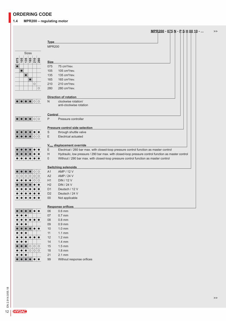
MPR200 - 075 N - P S H 00 10 - ...
TypeMPR200
Sizes
075
105
135
165
210
280
Sizel 075 75cm³/rev.l 105 105cm³/rev.l 135 135cm³/rev.l 165 165cm³/rev. 210 210cm³/rev. 280 280cm³/rev.
Direction of rotationl l l l N clockwiserotation/
anti-clockwiserotation
Controll l l l P Pressurecontroller
Pressure control side selectionl l l l l l S throughshuttlevalvel l l l E Electricalactuated
Vmax displacement overridel l l l l l E Electrical/260barmax.withclosed-looppressurecontrolfunctionasmastercontroll l l l l l H Hydraulic,lowpressure/290barmax.withclosed-looppressurecontrolfunctionasmastercontroll l l l l l 0 Without/290barmax.withclosed-looppressurecontrolfunctionasmastercontrol
Switching solenoidsl l l l A1 AMP / 12 V A2 AMP / 24 Vl l l l H1 DIN / 12 Vl l l l l l H2 DIN / 24 Vl l l l l l D1 Deutsch/12Vl l l l l l D2 Deutsch/24Vl l l l l l 00 Notapplicable
Response orificesl l l l l l 06 0.6mml l l 07 0.7mml l l l l l 08 0.8mml l l 09 0.9mml l l l l l 10 1.0mml l l 11 1.1mml l l l l l 12 1.2mml l l 14 1.4mml l l 15 1.5mml l l 18 1.8mml l l 21 2.1mml l l l l l 99 Withoutresponseorifices
ORDERING CODE 1.4 MPR200 – regulating motor
>>
>>
13
EN
2.9
14.0
/05.
18
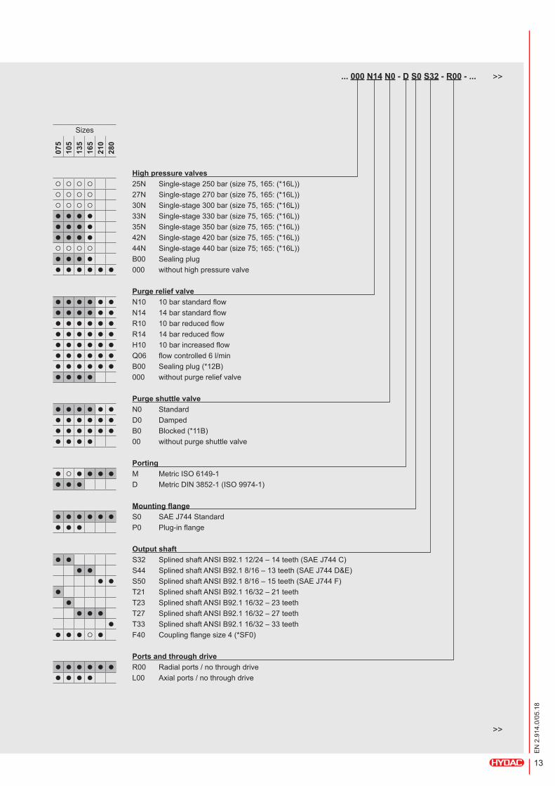
... 000 N14 N0 - D S0 S32 - R00 - ...
Sizes
075
105
135
165
210
280
High pressure valves 25N Single-stage250bar(size75,165:(*16L)) 27N Single-stage270bar(size75,165:(*16L)) 30N Single-stage300bar(size75,165:(*16L))l l l l 33N Single-stage330bar(size75,165:(*16L))l l l l 35N Single-stage350bar(size75,165:(*16L))l l l l 42N Single-stage420bar(size75,165:(*16L)) 44N Single-stage440bar(size75;165:(*16L))l l l l B00 Sealingplugl l l l l l 000 withouthighpressurevalve
Purge relief valvel l l l l l N10 10barstandardflowl l l l l l N14 14barstandardflowl l l l l l R10 10barreducedflowl l l l l l R14 14barreducedflowl l l l l l H10 10barincreasedflowl l l l l l Q06 flowcontrolled6l/minl l l l l l B00 Sealingplug(*12B)l l l l 000 withoutpurgereliefvalve
Purge shuttle valvel l l l l l N0 Standardl l l l l l D0 Dampedl l l l l l B0 Blocked(*11B)l l l l 00 withoutpurgeshuttlevalve
Portingl l l l l M MetricISO6149-1l l l D MetricDIN3852-1(ISO9974-1)
Mounting flangel l l l l l S0 SAEJ744Standardl l l P0 Plug-inflange
Output shaftl l S32 SplinedshaftANSIB92.112/24–14teeth(SAEJ744C)
l l S44 SplinedshaftANSIB92.18/16–13teeth(SAEJ744D&E)l l S50 SplinedshaftANSIB92.18/16–15teeth(SAEJ744F)
l T21 SplinedshaftANSIB92.116/32–21teethl T23 SplinedshaftANSIB92.116/32–23teethl l l T27 SplinedshaftANSIB92.116/32–27teeth
l T33 SplinedshaftANSIB92.116/32–33teethl l l l F40 Couplingflangesize4(*SF0)
Ports and through drivel l l l l l R00 Radialports/nothroughdrivel l l l L00 Axialports/nothroughdrive
>>
>>
14
EN
2.9
14.0
/05.
18
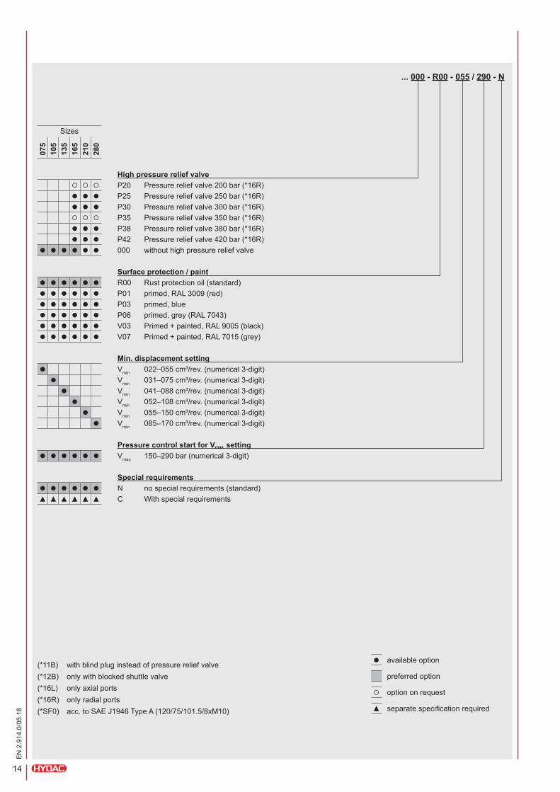
... 000 - R00 - 055 / 290 - N
Sizes
075
105
135
165
210
280
High pressure relief valve P20 Pressurereliefvalve200bar(*16R)l l l P25 Pressurereliefvalve250bar(*16R)l l l P30 Pressurereliefvalve300bar(*16R) P35 Pressurereliefvalve350bar(*16R)l l l P38 Pressurereliefvalve380bar(*16R)l l l P42 Pressurereliefvalve420bar(*16R)
l l l l l l 000 withouthighpressurereliefvalve
Surface protection / paintl l l l l l R00 Rustprotectionoil(standard)l l l l l l P01 primed,RAL3009(red)l l l l l l P03 primed,bluel l l l l l P06 primed,grey(RAL7043)l l l l l l V03 Primed+painted,RAL9005(black)l l l l l l V07 Primed+painted,RAL7015(grey)
Min. displacement settingl Vmin 022–055cm³/rev.(numerical3-digit)l Vmin 031–075cm³/rev.(numerical3-digit)l Vmin 041–088cm³/rev.(numerical3-digit)l Vmin 052–108cm³/rev.(numerical3-digit)l Vmin 055–150cm³/rev.(numerical3-digit)l Vmin 085–170cm³/rev.(numerical3-digit)
Pressure control start for Vmax settingl l l l l l Vmax 150–290bar(numerical3-digit)
Special requirementsl l l l l l N nospecialrequirements(standard)▲ ▲ ▲ ▲ ▲ ▲ C Withspecialrequirements
(*11B) withblindpluginsteadofpressurereliefvalve(*12B) onlywithblockedshuttlevalve(*16L) onlyaxialports(*16R) onlyradialports(*SF0) acc.toSAEJ1946TypeA(120/75/101.5/8xM10)
l availableoption
preferredoption
optiononrequest
▲ separatespecificationrequired

15
EN
2.9
14.0
/05.
18
TECHNICAL INFORMATION2.1 Specifications
Motor size 28 35 55 63 75 85 105 135 165 210 280
Displace-ment
Vmax
[cm³/rev]
28.6 35.6 54.7 63 75.9 85 105 135.6 165.6 210.1 281.9
Vmin
(Onlyfordisplacementandregulatingmotors)
– – 18.3 25.3 25.3 35 35 45.2 55.2 70 93
Pressure
Nominalpressure
[bar]
450
Peakpressure(short-term) 500
Min.pressureHPside"P" 20
Min.pressureLPside"S" 10
Permissiblehousinginnerpressure 2.5
Pressureaccelerationspeed [bar/s] 10,000
Drive speed
Max.operatingdrivespeed(at100%dutycycle)atmax.displacement
[rpm]
4,300 4,300 4,300 3,800 3,800 3,700 3,700 3,200 3,100 2,700 2,400
Peakdrivespeed (short-term<10sec.)Atmax.displacement, higherdrivespeedsonrequest
4,400 4,400 4,400 4,100 4,100 3,800 3,800 3,500 3,400 3,000 2,700
Max.operatingdrivespeed(at100%dutycycle)atmin.displacement
– – 4,700 4,400 4,400 4,100 4,100 3,700 3,500 3,200 2,900
Peakdrivespeed (short-term<10sec.)Atmin.displacement, higherdrivespeedsonrequest
– – 5,300 5,000 5,000 4,700 4,700 4,000 3,900 3,500 3,200
Power
Switchingcapacity(at100%Vmax max.operationspeed,atVmin nominalpressureand20barchargepressure->∆p430bar)
[kW] 86 108 184 239 239 309 309 360 415 482 586
Torque Max.outputtorque(undernominalpressure)
[Nm] 196 244 374 519 519 719 719 928 1,133 1,438 1,929
Permissible housing temperaturewith permissible viscosity > 10 cSt
[°C] 90
Weight
Fixeddisplacementmotor(With2-holeflange)
[kg]
16 16 19 26 26 33 33 39 76 101 146
Variabledisplacementandregulatingmotor(With2-or4-holeflange)
– – 28 32 32 42 42 56 76 101 146
Moment of inertia [kgm²] 0.0025 0.0025 0.0049 0.0076 0.0079 0.0144 0.0144 0.0215 0.0306 0.0468 0.0936
Permissible radial force on output shaft [N] onrequest
Permissible axial force on output shaft [N] 2000,highervaluesonrequest
16
EN
2.9
14.0
/05.
18
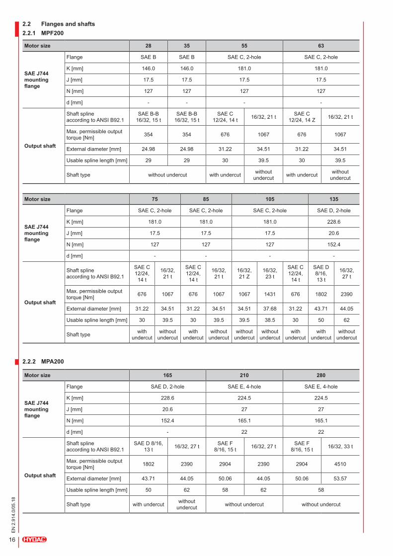
2.2 Flanges and shafts2.2.1 MPF200
Motor size 28 35 55 63
SAE J744 mounting flange
Flange SAE B SAE B SAEC,2-hole SAEC,2-hole
K[mm] 146.0 146.0 181.0 181.0
J[mm] 17.5 17.5 17.5 17.5
N[mm] 127 127 127 127
d[mm] - - - -
Output shaft
Shaftspline accordingtoANSIB92.1
SAEB-B 16/32,15t
SAEB-B 16/32,15t
SAEC 12/24,14t 16/32,21t SAEC
12/24, 14 Z 16/32,21t
Max.permissibleoutputtorque[Nm] 354 354 676 1067 676 1067
Externaldiameter[mm] 24.98 24.98 31.22 34.51 31.22 34.51
Usablesplinelength[mm] 29 29 30 39.5 30 39.5
Shafttype withoutundercut withundercut withoutundercut withundercut without
undercut
Motor size 75 85 105 135
SAE J744 mounting flange
Flange SAEC,2-hole SAEC,2-hole SAEC,2-hole SAED,2-hole
K[mm] 181.0 181.0 181.0 228.6
J[mm] 17.5 17.5 17.5 20.6
N[mm] 127 127 127 152.4
d[mm] - - - -
Output shaft
Shaftspline accordingtoANSIB92.1
SAEC12/24, 14t
16/32,21t
SAEC12/24, 14t
16/32,21t
16/32,21 Z
16/32,23t
SAEC12/24, 14t
SAE D 8/16,13t
16/32,27t
Max.permissibleoutputtorque[Nm] 676 1067 676 1067 1067 1431 676 1802 2390
Externaldiameter[mm] 31.22 34.51 31.22 34.51 34.51 37.68 31.22 43.71 44.05
Usablesplinelength[mm] 30 39.5 30 39.5 39.5 38.5 30 50 62
Shafttype withundercut
withoutundercut
withundercut
withoutundercut
withoutundercut
withoutundercut
withundercut
withundercut
withoutundercut
Motor size 165 210 280
SAE J744 mounting flange
Flange SAED,2-hole SAEE,4-hole SAEE,4-hole
K[mm] 228.6 224.5 224.5
J[mm] 20.6 27 27
N[mm] 152.4 165.1 165.1
d[mm] - 22 22
Output shaft
Shaftspline accordingtoANSIB92.1
SAED8/16,13t 16/32,27t SAE F
8/16,15t 16/32,27t SAE F 8/16,15t 16/32,33t
Max.permissibleoutputtorque[Nm] 1802 2390 2904 2390 2904 4510
Externaldiameter[mm] 43.71 44.05 50.06 44.05 50.06 53.57
Usablesplinelength[mm] 50 62 58 62 58
Shafttype withundercut withoutundercut withoutundercut withoutundercut
2.2.2 MPA200
17
EN
2.9
14.0
/05.
18
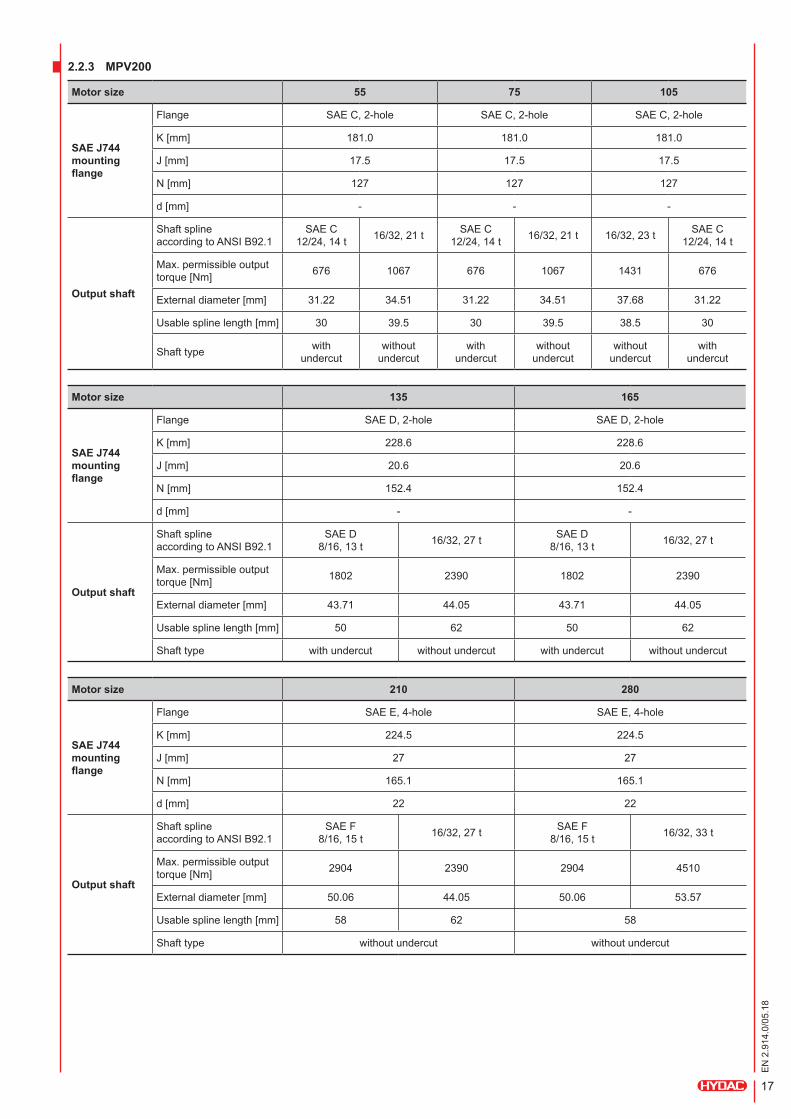
2.2.3 MPV200
Motor size 55 75 105
SAE J744 mounting flange
Flange SAEC,2-hole SAEC,2-hole SAEC,2-hole
K[mm] 181.0 181.0 181.0
J[mm] 17.5 17.5 17.5
N[mm] 127 127 127
d[mm] - - -
Output shaft
Shaftspline accordingtoANSIB92.1
SAEC 12/24,14t 16/32,21t SAEC
12/24,14t 16/32,21t 16/32,23t SAEC 12/24,14t
Max.permissibleoutputtorque[Nm] 676 1067 676 1067 1431 676
Externaldiameter[mm] 31.22 34.51 31.22 34.51 37.68 31.22
Usablesplinelength[mm] 30 39.5 30 39.5 38.5 30
Shafttype with undercut
withoutundercut
with undercut
withoutundercut
withoutundercut
with undercut
Motor size 135 165
SAE J744 mounting flange
Flange SAED,2-hole SAED,2-hole
K[mm] 228.6 228.6
J[mm] 20.6 20.6
N[mm] 152.4 152.4
d[mm] - -
Output shaft
Shaftspline accordingtoANSIB92.1
SAE D 8/16,13t 16/32,27t SAE D
8/16,13t 16/32,27t
Max.permissibleoutputtorque[Nm] 1802 2390 1802 2390
Externaldiameter[mm] 43.71 44.05 43.71 44.05
Usablesplinelength[mm] 50 62 50 62
Shafttype withundercut withoutundercut withundercut withoutundercut
Motor size 210 280
SAE J744 mounting flange
Flange SAEE,4-hole SAEE,4-hole
K[mm] 224.5 224.5
J[mm] 27 27
N[mm] 165.1 165.1
d[mm] 22 22
Output shaft
Shaftspline accordingtoANSIB92.1
SAE F 8/16,15t 16/32,27t SAE F
8/16,15t 16/32,33t
Max.permissibleoutputtorque[Nm] 2904 2390 2904 4510
Externaldiameter[mm] 50.06 44.05 50.06 53.57
Usablesplinelength[mm] 58 62 58
Shafttype withoutundercut withoutundercut
18
EN
2.9
14.0
/05.
18
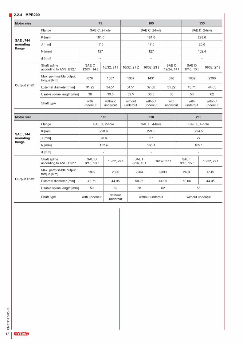
Motor size 75 105 135
SAE J744 mounting flange
Flange SAEC,2-hole SAEC,2-hole SAED,2-hole
K[mm] 181.0 181.0 228.6
J[mm] 17.5 17.5 20.6
N[mm] 127 127 152.4
d[mm] - - -
Output shaft
Shaftspline accordingtoANSIB92.1
SAEC 12/24,14t 16/32,21t 16/32,21Z 16/32,23t SAEC
12/24,14tSAE D
8/16,13t 16/32,27t
Max.permissibleoutputtorque[Nm] 676 1067 1067 1431 676 1802 2390
Externaldiameter[mm] 31.22 34.51 34.51 37.68 31.22 43.71 44.05
Usablesplinelength[mm] 30 39.5 39.5 38.5 30 50 62
Shafttype with undercut
withoutundercut
withoutundercut
withoutundercut
with undercut
with undercut
withoutundercut
Motor size 165 210 280
SAE J744 mounting flange
Flange SAED,2-hole SAEE,4-hole SAEE,4-hole
K[mm] 228.6 224.5 224.5
J[mm] 20.6 27 27
N[mm] 152.4 165.1 165.1
d[mm] - - -
Output shaft
Shaftspline accordingtoANSIB92.1
SAE D 8/16,13t 16/32,27t SAE F
8/16,15t 16/32,27t SAE F 8/16,15t 16/32,27t
Max.permissibleoutputtorque[Nm] 1802 2390 2904 2390 2404 4510
Externaldiameter[mm] 43.71 44.05 50.06 44.05 50.06 44.05
Usablesplinelength[mm] 50 62 58 62 58
Shafttype withundercut withoutundercut withoutundercut withoutundercut
2.2.4 MPR200

19
EN
2.9
14.0
/05.
18
K
D1
L1 L2 F3
F1 F2 D2
F4
Plug-in housing for MPF200 / MPV200 / MPR200 Size 75 / 105 / 135
Mounting flange
Usable toothlength Usable
toothlength
External
diam
eter
External
diam
eter
Dimensions of output shaft without undercut Dimensions of output shaft with undercut
Output shafts
2-hole flange 4-hole flange
K
K
d
KN
N
20
EN
2.9
14.0
/05.
18
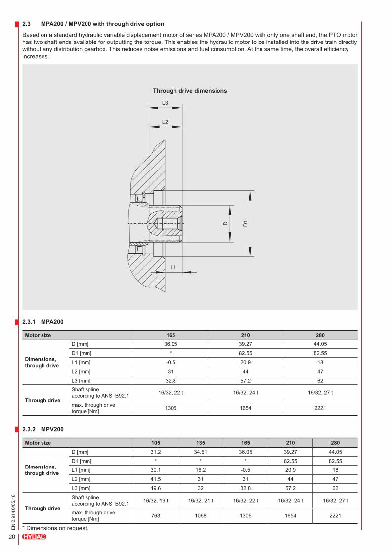
2.3.1 MPA200
Motor size 165 210 280
Dimensions, through drive
D[mm] 36.05 39.27 44.05
D1[mm] * 82.55 82.55
L1[mm] -0.5 20.9 18
L2[mm] 31 44 47
L3[mm] 32.8 57.2 62
Through drive
Shaftspline accordingtoANSIB92.1 16/32,22t 16/32,24t 16/32,27t
max.throughdrivetorque[Nm] 1305 1654 2221
2.3.2 MPV200
Motor size 105 135 165 210 280
Dimensions, through drive
D[mm] 31.2 34.51 36.05 39.27 44.05
D1[mm] * * * 82.55 82.55
L1[mm] 30.1 16.2 -0.5 20.9 18
L2[mm] 41.5 31 31 44 47
L3[mm] 49.6 32 32.8 57.2 62
Through drive
Shaftspline accordingtoANSIB92.1 16/32,19t 16/32,21t 16/32,22t 16/32,24t 16/32,27t
max.throughdrivetorque[Nm] 763 1068 1305 1654 2221
*Dimensionsonrequest.
2.3 MPA200 / MPV200 with through drive option
BasedonastandardhydraulicvariabledisplacementmotorofseriesMPA200/MPV200withonlyoneshaftend,thePTOmotorhastwoshaftendsavailableforoutputtingthetorque.Thisenablesthehydraulicmotortobeinstalledintothedrivetraindirectlywithoutanydistributiongearbox.Thisreducesnoiseemissionsandfuelconsumption.Atthesametime,theoverallefficiencyincreases.
Through drive dimensions
L3
L2
L1
D D1
21
EN
2.9
14.0
/05.
18
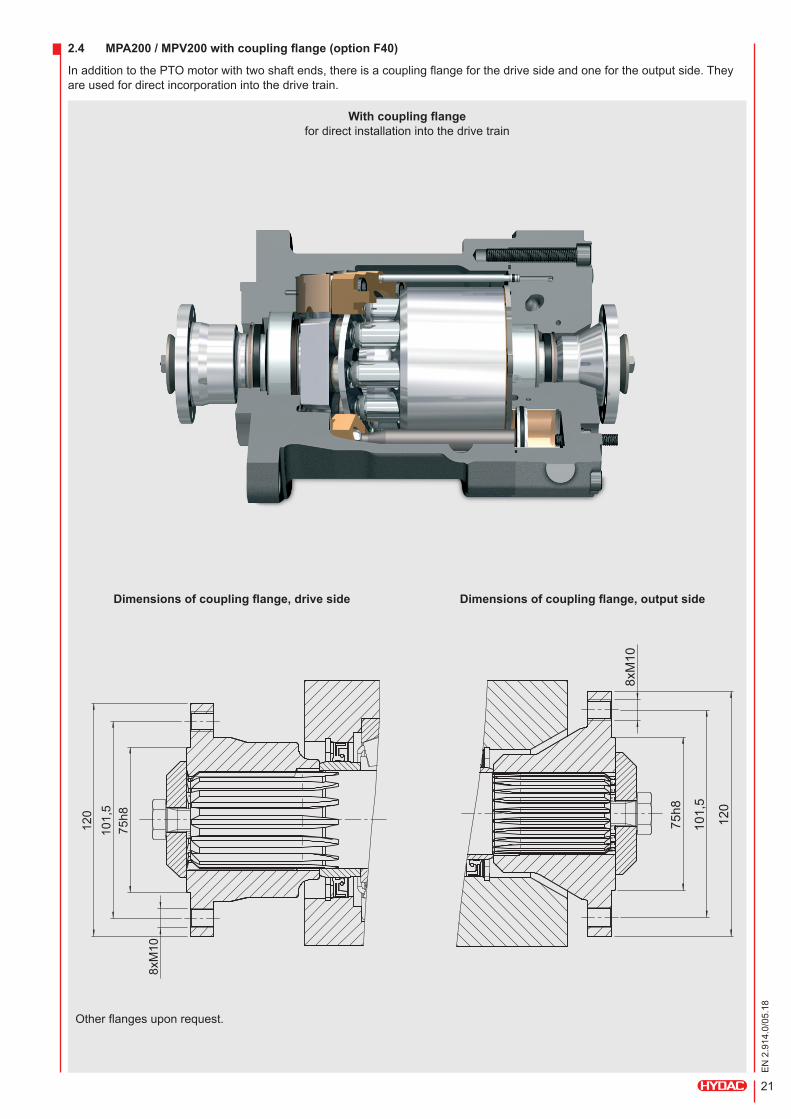
2.4 MPA200 / MPV200 with coupling flange (option F40)
InadditiontothePTOmotorwithtwoshaftends,thereisacouplingflangeforthedrivesideandonefortheoutputside.Theyareusedfordirectincorporationintothedrivetrain.
With coupling flange fordirectinstallationintothedrivetrain
Dimensions of coupling flange, drive side Dimensions of coupling flange, output side
Otherflangesuponrequest.
75h
8 1
01,5
1
20
8xM
10
75h
8
101
,5
120
8xM
10
22
EN
2.9
14.0
/05.
18
2.5 Seals
Themotorseriesisequippedwithfluorocarbon(FPM)sealsasstandard.
Whenusingspecialfluidsorinaparticularlylowambienttemperature,thesealmaterialmightneedtobereplaced.
Forusewithothersealingmaterials,pleasecontactHYDACDriveCenter.
2.6 Filtration
Highoilcleanlinessgreatlycontributestolengtheningtheservicelifeofthehydraulicsystem.
For high functional reliability and service life
18/16/13asperISO4406 orbetter
Minimum requirement 20/18/15asperISO4406
Delivery Theminimumrequirementforthecleanlinessofthehydraulicoilisbasedonthemostsensitivecomponentinthesystem.
Filling and operating hydraulic systems
Whenfillingorrefilling,itmustbeguaranteedthattherequiredcleanlinessofthehydraulicoilisadheredto.Asarule,fillingfrombarrels,canistersorlargetanksnecessitatespre-filteringoftheoil.Itisrecommendedtotakeappropriatemeasures(e.g.filters)toensurethattherequiredoilcleanlinessismaintainedevenduringoperation.
International standards
Codenumber accordingtoISO4406 18/16/13 20/18/15
Codenumber accordingtoNAS: 7 9
2.7 Hydraulic fluids
Themotorseriesisdesignedforusewith:
HLP HydraulicoilsofR&Otype (rustandoxidationinhibitor)
Biodegradable oils accordingtoISO15380,onrequest
Forusewithotherfluids,pleasecontact HYDACDriveCenter.
2.8 Temperature range
-20 °C to +90 °C oil temperature
Notice: Thehighestfluidtemperaturewillbeatthedrainportofthemotor.Thisisupto20°Chigherthaninthereservoir.
2.9 Viscosity range
Minimum viscosity: 10cSt(mm²/s)
Operating viscosity: 20–80cSt(mm²/s)
Maximum viscosity: 1,000cSt(mm²/s)
Minimum viscosity = 10mm²/sshort-term(t≤1min)atamaximumpermissibleleakagefluidtemperatureof+95°C
Maximum viscosity = 1,000mm²/sshort-term(t≤1min)oncoldstart(p≤30bar,n≤1,000rev./min,tmin-10°C)
Forlowtemperatureapplications,pleasecontactHYDACDriveCenter.

23
EN
2.9
14.0
/05.
18
2.10 Installation instructions
Theinstallationofthehydraulicassemblymustbeperformedaccordingtothewireandpipingdiagramandaccordingtothedevice-specificinstallationinstructionaswellasthetechnicaldatasheetsandinstallationdrawings.
Ifelectro-hydrauliccircuitsareperformed,itmustbeobservedthattheprescribedelectricalvaluesareadheredtoand,forexample,thedevicehastheprescribedvoltage.
Forthehydraulicpipes,seamlessprecisionsteelpipesaccordingtoEN10305/Corhoseswithsuitablepressureresistancemustbeused.Thepipesmustbedeburred,washedoutandblownthrough.Scaledorrustedpipesmustbepickledandthenneutralised;brushoutanydecontiminatedhosesandthenrinse.
Cleanlinessisthepriorityduringinstallationoftheentirehydraulicunit.Donotplugorclosefinishedpipeswithcleaningclothsbutratherwithplasticfilmortape.Neverusecleaningwool.
General information on the mechanical connection
ThemechanicalconnectionofaHYDACaxialpistonmotortothedrivesystemisperformedviaitshousingflangeandtheprimaryoutputshaft.Thecouplingwiththeoutputshaftmustbesetupwithoutanyradialoraxialshaftoffset. Seethetechnicaldatasheet,theinstallationdiagramorthecataloguefortherelevantpermissiblevaluesofthetransmittedshafttorquesandtheactingaxialforces.
Radialforcesontheshaftendmustbeprevented.If,forspecificdrivetechniquereasonsorconstructionconsiderations,radialforcesontheshaftendofaHYDACaxialpistonmotorcannotbeavoided,pleaseconsultusalreadyattheprojectdesignrange.
Shafts
InHYDACaxialpistonmotors,theshaftendsoftheprimarydriveoroutputshaftsareusuallydesignedasflangecentringsplinedshaftswithinvolutereferenceprofilesaccordingtoANSIB92.1.Theprescribedcounterfittinginconnection,gearorbeltpulleymustbeobserved.
Generally,duringboththeinstallationanddismantlingoftheoutputelements,noshockorimpactforces(e.g.hammerblows)mayactontheshaftendsofHYDACaxialpistonmotors,asthiswillinevitablyresultindamagetothetransmissiongearandinparticulartotheshaftbearing.
Toavoidrotaryoscillationintheoutputtrain,flexibleconnectionsmustbeusedwithdynamictransmissioncharacteristicscoordinatedtotheoutputsystem.Inparticular,itmustbeensuredthatthesystemisresonance-free.
Cardan shafts
Theinstallationinstructionsofthecardanshaftmanufacturermustbeobserved! PleasecontactHYDACDriveCenterbeforeinstallation. Inordertoavoidrotaryoscillations,itmustbeobservedthatcardanshaftpiecesontheoutletsideareatthesameangleandinonelevel.Onlyusebalancedcardanshaftsandensurecorrectpositioningwhenpluggingthecardanjoints!
Permissible output and through drive torques
Itmustbeensuredthatthepermissibletorqueisnotexceededinanyoperationalstate.Pleaseseethepermissiblevaluesinthetechnicaldatasheetorcatalogue.
Hydraulic motors
Whenplanningtheoverallsystemandinthesubsequentimplementationoftheinstallation,itmustbeensuredthatthehousingofthehydraulicpumpandofthehydraulicmotorisfullyfilledwithhydraulicfluidinalloperatingmodesafterfirstfillingandbleedingwithintheframeworkoftheinitialstart-up,andcannotrunemptyduringoperationnorduringtemporaryorlongerstandstill.
Installation
Ideallyhorizontalinstallation.
ForalternativeinstallationspleasecontacttheHYDACDriveCenter.

24
EN
2.9
14.0
/05.
18
2.11 Piping example
Diagramsvalidforclockwisedriverotation.
*Dependentonmotortype,see5.5Connections–Flowdirection
Tank
F
LS
A
B
PU
B A L
L2
Cooler Highpressure
Lowpressure
Chargepressure
Tankpressure
Tank
Cooler
F
A
W
X
S
PU(L) L2 L(U)
U(L)
Highpressure
Lowpressure
Chargepressure
Tankpressure
L1
B
A
Onrequest: l chargepumpwithinternalsuction l oilcoolerinlow-pressurecircuit l onlyfornominalsizes55–135
lPressureentryatA:clockwiserotation* lPressureentryatB:anti-clockwiserotation*

25
EN
2.9
14.0
/05.
18
MOTOR VARIANTS3.1 Function overview
HYDACsuppliesfixeddisplacement,regulatingandvariabledisplacementmotorswithhighstart-uptorquesfortheopenandtheclosedcircuit.Themotorsarecontrolledelectricallyorhydraulically.
Motor type Control / function Product
Fixed displacement motor
– MPF200
Displacementmanuallyadjustable MPA200
Variable displacement motor
Variableadjustable,hydraulic MPV200 H1, H4
Variableadjustable,electrical MPV200E1(E1F),E4(E4F),E6(E6F)
Twopositioncontol,hydraulicallyswitchable MPV200 H2
Twopositioncontrol,electricallyswitchable MPV200E2(E2F)
Variableadjustable,pressureoverride,electricalselectionofpressuresignal
MPV200EH1P/MPV200EH1PCA
regulating motor
Vmaxhydraulic,lowpressure MPR200
Vmaxelectrical MPR200

26
EN
2.9
14.0
/05.
18
3.2 MPF200
ThemotorMPF200canbeusedforopenandclosedcircuits.
Design features: lOptimisedstart-upandlow-speedperformance lOptionallywithpurgereliefvalvestorinseoutcircuitandhousing l Fixed-settingandswitchablehighpressurereliefvalveoptional
Fixed displacement motor MPF200
A, B WorkportsL, U Drainports
LA
B
U
3.3 MPA200
ThemotorMPA200canbeusedforopenandclosedcircuits.Thespecificdisplacementissettoaparticularvalue.Thespecificdisplacementissetmechanicallybymeansofanadjustmentscrew.
MPA200 as manually adjustable fixed displacement motor
A, B WorkportsL, U Drainports
purgereliefoptional
LW
A
U
Design features: lOptimisedstart-upandlow-speedperformance
27
EN
2.9
14.0
/05.
18
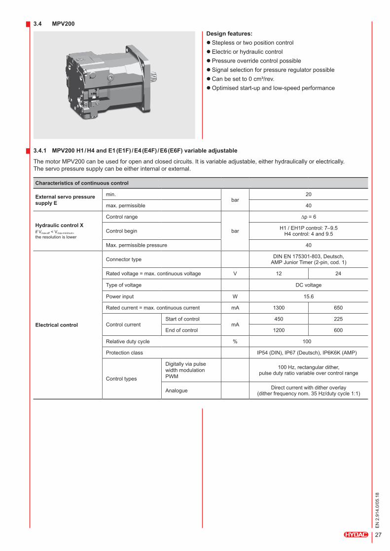
3.4 MPV200Design features:
lSteplessortwopositioncontrol lElectricorhydrauliccontrol lPressureoverridecontrolpossible lSignalselectionforpressureregulatorpossible lCanbesetto0cm³/rev. lOptimisedstart-upandlow-speedperformance
3.4.1 MPV200 H1 / H4 and E1 (E1F) / E4 (E4F) / E6 (E6F) variable adjustable
ThemotorMPV200canbeusedforopenandclosedcircuits.Itisvariableadjustable,eitherhydraulicallyorelectrically. Theservopressuresupplycanbeeitherinternalorexternal.
Characteristics of continuous control
External servo pressure supply E
min.bar
20
max.permissible 40
Hydraulic control XifVmax-eff<Vmax-minimum, theresolutionislower
Controlrange
bar
∆p=6
Controlbegin H1/EH1Pcontrol:7–9.5 H4control:4and9.5
Max.permissiblepressure 40
Electrical control
Connectortype DINEN175301-803,Deutsch, AMPJuniorTimer(2-pin,cod.1)
Ratedvoltage=max.continuousvoltage V 12 24
Typeofvoltage DCvoltage
Powerinput W 15.6
Ratedcurrent=max.continuouscurrent mA 1300 650
ControlcurrentStartofcontrol
mA450 225
Endofcontrol 1200 600
Relativedutycycle % 100
Protectionclass IP54(DIN),IP67(Deutsch),IP6K6K(AMP)
Controltypes
DigitallyviapulsewidthmodulationPWM
100Hz,rectangulardither, pulsedutyratiovariableovercontrolrange
Analogue Directcurrentwithditheroverlay (ditherfrequencynom.35Hz/dutycycle1:1)
28
EN
2.9
14.0
/05.
18
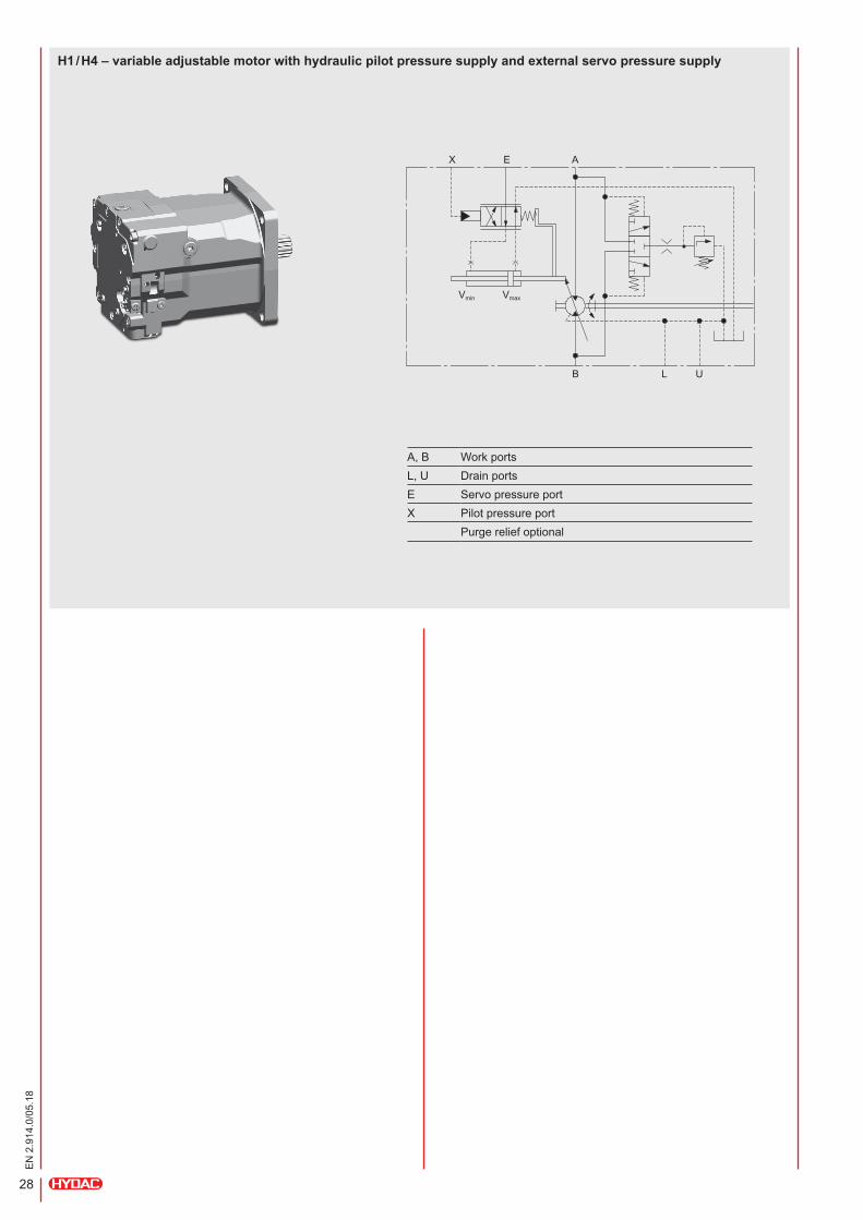
H1 / H4 – variable adjustable motor with hydraulic pilot pressure supply and external servo pressure supply
A, B WorkportsL, U DrainportsE ServopressureportX Pilotpressureport
Purgereliefoptional
EX
Vmin Vmax
A
LB U
29
EN
2.9
14.0
/05.
18
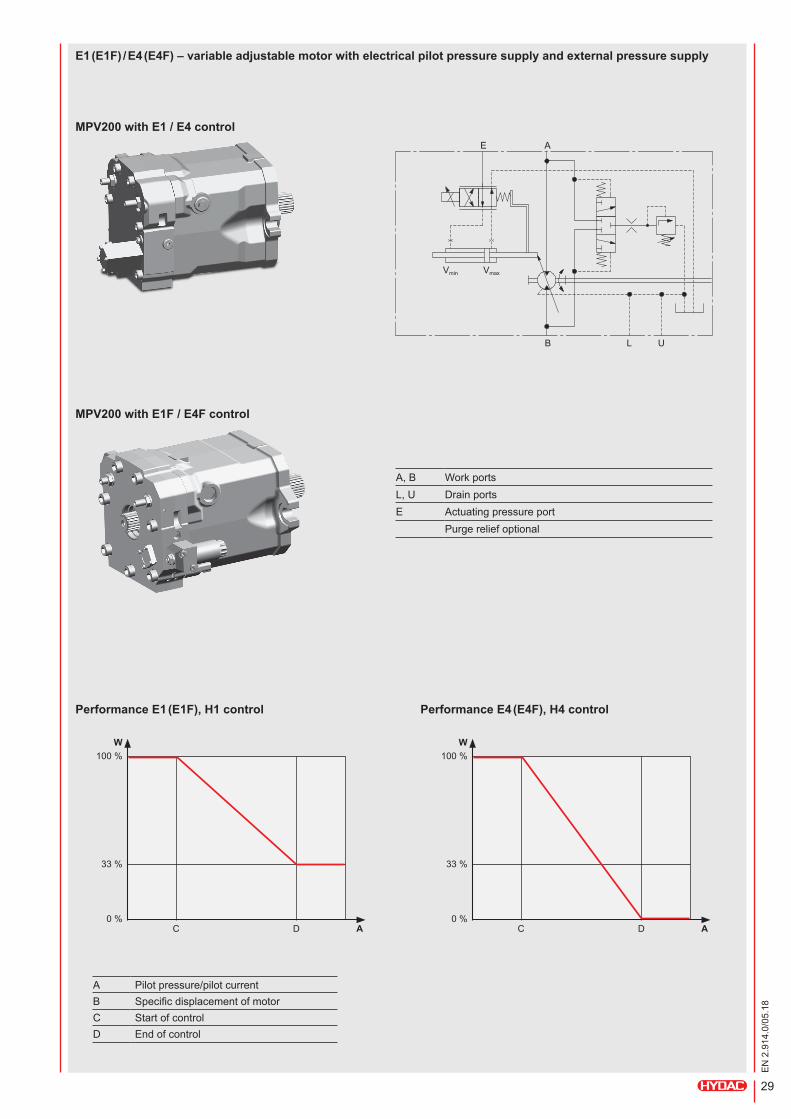
E1 (E1F) / E4 (E4F) – variable adjustable motor with electrical pilot pressure supply and external pressure supply
A, B WorkportsL, U DrainportsE Actuatingpressureport
Purgereliefoptional
E
Vmin Vmax
A
LB U
MPV200 with E1F / E4F control
MPV200 with E1 / E4 control
A
33%
0%
100%W
C D
Performance E1 (E1F), H1 control
A
33%
0%
100%W
C D
Performance E4 (E4F), H4 control
A Pilotpressure/pilotcurrentB SpecificdisplacementofmotorC StartofcontrolD Endofcontrol

30
EN
2.9
14.0
/05.
18
E6 (E6F) – variable adjustable motor with electrical pilot pressure supply and external servo pressure supply (side-mounted)
E
Vmin Vmax
A
LB U
A, B WorkportsL, U DrainportsE Servopressureport
Purgereliefoptional
A
33%
0%
100%W
C D
Performance E6(E6F) control
A Pilotpressure/pilotcurrentB SpecificdisplacementofmotorC StartofcontrolD Endofcontrol
MPV200 with E6 control
MPV200 with E6F control
31
EN
2.9
14.0
/05.
18
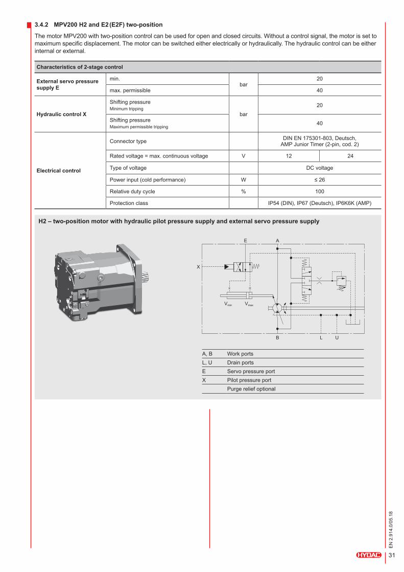
3.4.2 MPV200 H2 and E2 (E2F) two-position
ThemotorMPV200withtwo-positioncontrolcanbeusedforopenandclosedcircuits.Withoutacontrolsignal,themotorissettomaximumspecificdisplacement.Themotorcanbeswitchedeitherelectricallyorhydraulically.Thehydrauliccontrolcanbeeitherinternalorexternal.
Characteristics of 2-stage control
External servo pressure supply E
min.bar
20
max.permissible 40
Hydraulic control X
ShiftingpressureMinimumtripping
bar20
ShiftingpressureMaximumpermissibletripping
40
Electrical control
Connectortype DINEN175301-803,Deutsch, AMPJuniorTimer(2-pin,cod.2)
Ratedvoltage=max.continuousvoltage V 12 24
Typeofvoltage DCvoltage
Powerinput(coldperformance) W ≤26
Relativedutycycle % 100
Protectionclass IP54(DIN),IP67(Deutsch),IP6K6K(AMP)
H2 – two-position motor with hydraulic pilot pressure supply and external servo pressure supply
A, B WorkportsL, U DrainportsE ServopressureportX Pilotpressureport
Purgereliefoptional
E
X
Vmin Vmax
A
LB U

32
EN
2.9
14.0
/05.
18
E2 (E2F) – two-position motor with electrical pilot pressure supply and external servo pressure supply
A, B WorkportsL, U DrainportsE Servopressureport
Purgereliefoptional
E
Vmin Vmax
A
LB U
MPV200 with E2F control
MPV200 with E2 control
Performance MPV200 H2 and E2 (E2F) two-position
Switching signal0 max.
max.
min.
Dis
plac
emen
t

33
EN
2.9
14.0
/05.
18
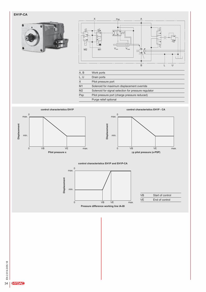
3.4.3 MPV200 EH1P, EH1P-CA variable adjustable with pressure override
TheMPV200motorcanbeusedforbothopenandclosedcircuits.
EH1P: Withoutcontrolsignal,theEH1PcontrolissettomaximumspecificdisplacementVmax.ThecontinuouscontrolfromVmaxtoVminishydraulicallyproportional,viatheexternalcontrolpressureatportX. Thiscontrolfunctionisoverlainbyapressureoverride:ifthepressureexceedsaparticularlevelinoneofthetwoworkinglines,thecontrolpressureatportXisdepressurisedtothetankandthemotorswivelsbacktoitsmaximumspecificdisplacementVmax.Thepressurelevelforcontrolstartmustbedefinedwhentheorderisplaced. TheEH1PcontrolalsoprovidestheoptionofpressurecontrolsidepreselectionviasolenoidvalveM2.
EH1P-CA: Withoutcontrolsignal,theEH1P-CAcontrolissettomaximumdisplacementVmax.ThecontinuouscontrolfromVmaxtoVminishydraulicallyproportionalinaccordancewiththepressuredifferencebetweencontrolpressureportXandservopressuresupplyatportPsp.IncombinationwiththePPV200withCAcontrol,themotorswivelsbacktotheminimumdisplacementVminwithincreasingspeedofthedrivemotor. Thiscontrolfunctionisoverlainbyapressureoverride:ifthepressureexceedsaparticularlevelinoneofthetwoworkinglines,themotorswivelsbacktoitsmaximumdisplacementVmax.Thepressurelevelforcontrolstartmustbedefinedwhentheorderisplaced. TheEH1P-CAcontrolalsoprovidestheoptionofpressurecontrolsidepreselectionviasolenoidvalveM2.
Characteristics of continuous control with superimposed control
Hydraulic control X
Startofcontrol
bar
EH1P:7–9.5 EH1P-CA:7.5
Maximumpermittedpressure 40
Adjustingrange ∆p=6
Hydraulic closed-loop control
Startofpressurecontrol
Adjustable,specifywhileordering bar190–260
Endofpressurecontrol 5%abovestartofpressurecontrol
Electrical override Vmaxswitchingandpressurecontrolsideselection(fortechnicaldata,seeE2control)
Additional functions, integrated:
lElectricalVmaxswitchingindependentofcontrolpressureforfixeddisplacementmotoroperationwithelectricmastercontrolfunction lElectricalpressurecontrolsideselection
EH1P
A, B WorkportsL, U DrainportsX PilotpressureportM1 SolenoidformaximumdisplacementoverrideM2 Solenoidforsignalselectionforpressureregulator
Purgereliefoptional
X
M1M2Vmin Vmax
A
LB U
34
EN
2.9
14.0
/05.
18
EH1P-CA
A, B WorkportsL, U DrainportsX PilotpressureportM1 SolenoidformaximumdisplacementoverrideM2 SolenoidforsignalselectionforpressureregulatorPsp Pilotpressureport(chargepressurereduced)
Purgereliefoptional
X
M1M2 Vmin Vmax
APsp
LB U
Dis
plac
emen
t
Pilot pressure x
control characteristics EH1P
0
0
max.VEVB
max.
min.
Dis
plac
emen
t
Pressure difference working line lA-Bl
control characteristics EH1P and EH1P-CA
0
0
max.VEVB
max.
min.
Dis
plac
emen
t
∆p pilot pressure (x-PSP)
control characteristics EH1P - CA
0
0
max.VEVB
max.
min.
VB StartofcontrolVE Endofcontrol
35
EN
2.9
14.0
/05.
18
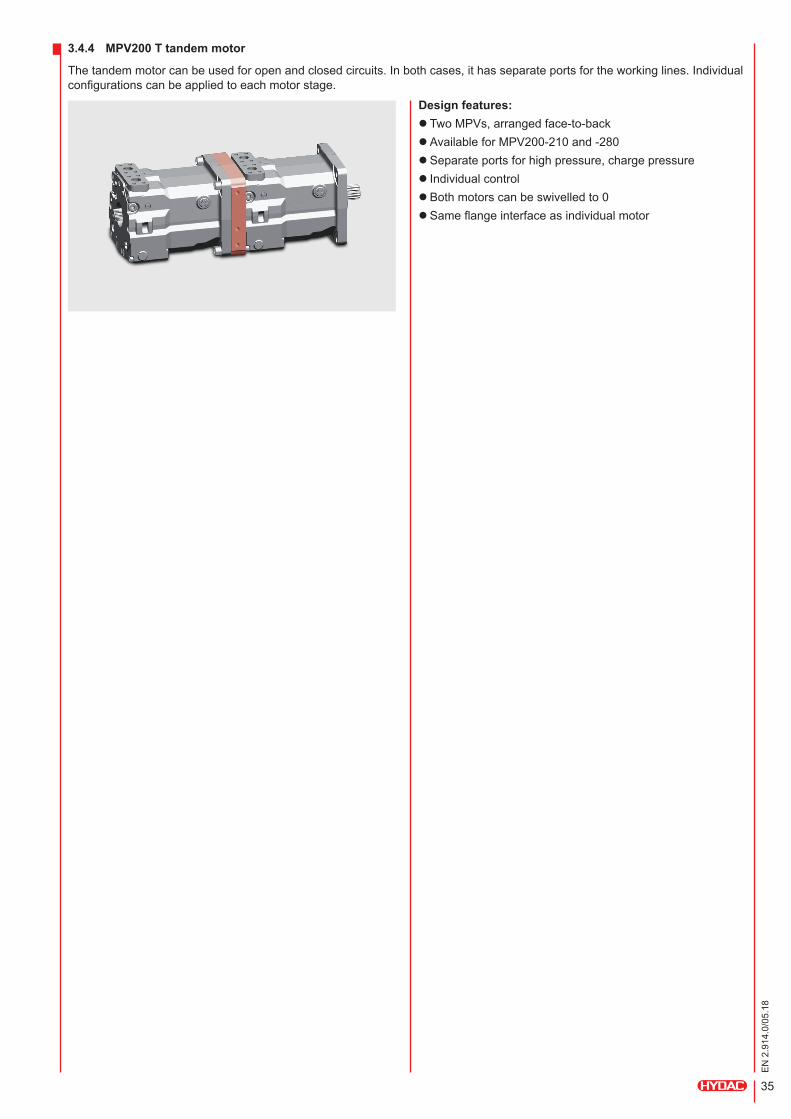
3.4.4 MPV200 T tandem motor
Thetandemmotorcanbeusedforopenandclosedcircuits.Inbothcases,ithasseparateportsfortheworkinglines.Individualconfigurationscanbeappliedtoeachmotorstage.
Design features: l TwoMPVs,arrangedface-to-back lAvailableforMPV200-210and-280 lSeparateportsforhighpressure,chargepressure l Individualcontrol lBothmotorscanbeswivelledto0 lSameflangeinterfaceasindividualmotor
36
EN
2.9
14.0
/05.
18
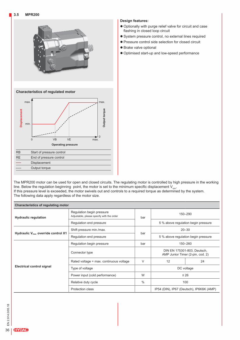
3.5 MPR200Design features:
lOptionallywithpurgereliefvalveforcircuitandcaseflashinginclosedloopcircuit lSystempressurecontrol,noexternallinesrequired lPressurecontrolsideselectionforclosedcircuit lBrakevalveoptional lOptimisedstart-upandlow-speedperformance
Characteristics of regulated motor
TheMPR200motorcanbeusedforopenandclosedcircuits.Theregulatingmotoriscontrolledbyhighpressureintheworkingline.Belowtheregulationbeginningpoint,themotorissettotheminimumspecificdisplacementVmin. Ifthispressurelevelisexceeded,themotorswivelsoutandcontrolstoarequiredtorqueasdeterminedbythesystem. Thefollowingdataapplyregardlessofthemotorsize.
Characteristics of regulating motor
Hydraulic regulationRegulationbeginpressureAdjustable,pleasespecifywiththeorder bar
150–290
Regulationendpressure 5%aboveregulationbeginpressure
Hydraulic Vmax override control X1Shiftpressuremin./max.
bar20–30
Regulationendpressure 5%aboveregulationbeginpressure
Electrical control signal
Regulationbeginpressure bar 150–260
Connectortype DINEN175301-803,Deutsch, AMPJuniorTimer(2-pin,cod.2)
Ratedvoltage=max.continuousvoltage V 12 24
Typeofvoltage DCvoltage
Powerinput(coldperformance) W ≤26
Relativedutycycle % 100
Protectionclass IP54(DIN),IP67(Deutsch),IP6K6K(AMP)
Dis
plac
emen
t
Out
put t
orqu
e
Operating pressure
RB StartofpressurecontrolRE Endofpressurecontrol
DisplacementOutputtorque
0 max.VEVB
max. max.
0
min.
37
EN
2.9
14.0
/05.
18
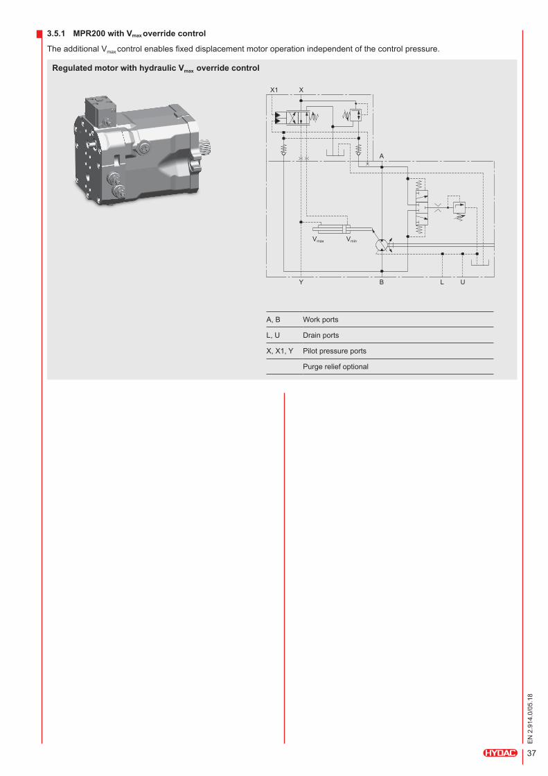
3.5.1 MPR200 with Vmax override control
TheadditionalVmaxcontrolenablesfixeddisplacementmotoroperationindependentofthecontrolpressure.
Regulated motor with hydraulic Vmax override control
A, B Workports
L, U Drainports
X,X1,Y Pilotpressureports
Purgereliefoptional
X1 X
A
Y B L U
VminVmax

38
EN
2.9
14.0
/05.
18
3.5.2 MPR200 pressure control side selection
Regulatingmotorsgenerallyswivelthetransmissiongeartothemaximumdisplacementwhenoperatingpressureishigh,regardlessofwhichsidethishighpressureison.Intransmissiondrivesthiscanresultinunpleasanteffects,suchasanextremelyseverebrakingeffectbeingproducedduringthetransitionfromdrivingonalevelsurfacewithlowsystempressuretocoasting.Selectingthepressurecontrolsidepreventsthecontrollerfrombeingexposedtothebrakingpressure,ensuringthatonlythedrivingpressureisswitchedtothepressurecontrolandthatthemotorremainsinminimumdisplacement.
A, B Workports
L, U Drainports
Y1 Pilotpressureport
Purgereliefoptional
A, B Workports
L, U Drainports
Y1 Pilotpressureport
Purgereliefoptional
MPR200 with electrical Vmax override control and signal selection for pressure regulator
MPR200 with electrical signal selection for pressure regulator
A
A
Y1
Y1
B
B
L
L
U
U
Vmin
Vmin
Vmax
Vmax

39
EN
2.9
14.0
/05.
18
ACCESSORIES4.1 Purge relief valve options
Thepurgereliefvalveoptionservesltoreducethetemperatureofthemotororthesystemintheclosedcircuitltoexchangetheoilinthecircuit
Purge flow in closed loop circuit
Version Purge flow in closed circuit Diagram Purge flow Diameter of
orifice
Standard 10bar 3 10l/minwith20barlowpressure 2.5mm
Standard 14bar 2 10l/minwith20barlowpressure withoutorifice
Reduced 10bar 3 5l/minwith20barlowpressure 2mm
Reduced 14bar 3 5l/minwith20barlowpressure 2.5mm
Increased 10bar 2 20l/minwith20barlowpressure withoutorifice
Quantity-controlled 14bar 4 6l/min Nooutput
Purge valve 1. – without (0 l/min)
Purge valve 4. – flow controlled
A, B WorkportsL, U Drainports
A, B WorkportsL, U Drainports
B
a
A
W
L
L
U
Purge valve 3. – restricted
A, B WorkportsL, U Drainports
A
W L U
Purge valve 2. – standard and increased
A, B WorkportsL, U Drainports
A
W L U
U
40
EN
2.9
14.0
/05.
18
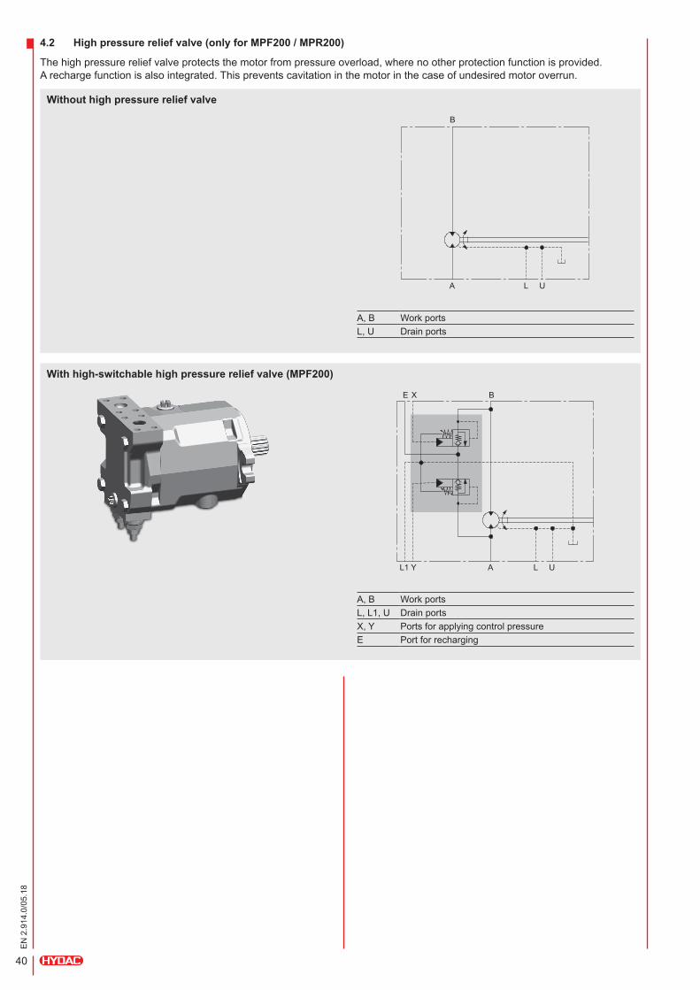
A, B WorkportsL, L1, U DrainportsX,Y PortsforapplyingcontrolpressureE Portforrecharging
4.2 High pressure relief valve (only for MPF200 / MPR200)
Thehighpressurereliefvalveprotectsthemotorfrompressureoverload,wherenootherprotectionfunctionisprovided. Arechargefunctionisalsointegrated.Thispreventscavitationinthemotorinthecaseofundesiredmotoroverrun.
L
With high-switchable high pressure relief valve (MPF200)
BE X
AL1 Y
Without high pressure relief valve
A, B WorkportsL, U Drainports
B
A L U
U

41
EN
2.9
14.0
/05.
18
With fixed high pressure relief valve (MPF200 / MPR200)
A, B WorkportsL, U DrainportsE Portforrecharging
WE
A L U
MPF200
MPR200
42
EN
2.9
14.0
/05.
18
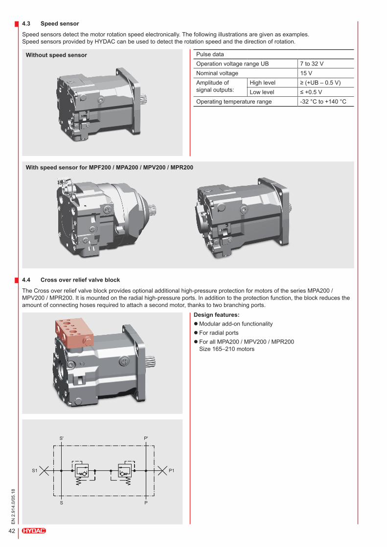
Without speed sensor
With speed sensor for MPF200 / MPA200 / MPV200 / MPR200
4.3 Speed sensor
Speedsensorsdetectthemotorrotationspeedelectronically.Thefollowingillustrationsaregivenasexamples. SpeedsensorsprovidedbyHYDACcanbeusedtodetecttherotationspeedandthedirectionofrotation.
4.4 Cross over relief valve block
TheCrossoverreliefvalveblockprovidesoptionaladditionalhigh-pressureprotectionformotorsoftheseriesMPA200/MPV200/MPR200.Itismountedontheradialhigh-pressureports.Inadditiontotheprotectionfunction,theblockreducestheamountofconnectinghosesrequiredtoattachasecondmotor,thankstotwobranchingports.
Design features: lModularadd-onfunctionality l Forradialports l ForallMPA200/MPV200/MPR200 Size165–210motors
Sʹ
S1 P1
S
Pʹ
P
PulsedataOperationvoltagerangeUB 7to32VNominalvoltage 15 VAmplitudeofsignaloutputs:
Highlevel ≥(+UB–0.5V)Lowlevel ≤+0.5V
Operatingtemperaturerange -32°Cto+140°C
43
EN
2.9
14.0
/05.
18
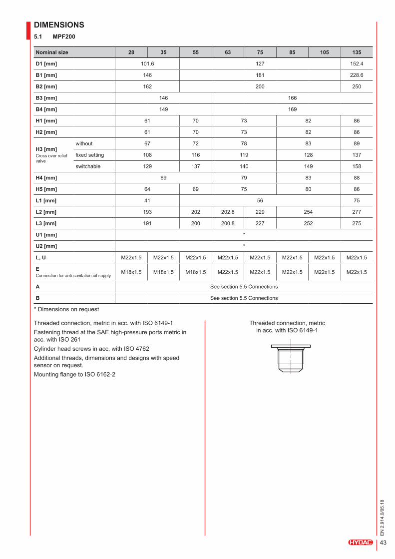
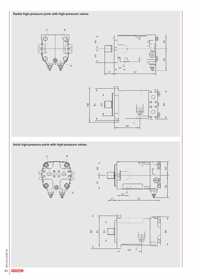
DIMENSIONS5.1 MPF200
Nominal size 28 35 55 63 75 85 105 135
D1 [mm] 101.6 127 152.4
B1 [mm] 146 181 228.6
B2 [mm] 162 200 250
B3 [mm] 146 166
B4 [mm] 149 169
H1 [mm] 61 70 73 82 86
H2 [mm] 61 70 73 82 86
H3 [mm]Crossoverreliefvalve
without 67 72 78 83 89
fixedsetting 108 116 119 128 137
switchable 129 137 140 149 158
H4 [mm] 69 79 83 88
H5 [mm] 64 69 75 80 86
L1 [mm] 41 56 75
L2 [mm] 193 202 202.8 229 254 277
L3 [mm] 191 200 200.8 227 252 275
U1 [mm] *
U2 [mm] *
L, U M22x1.5 M22x1.5 M22x1.5 M22x1.5 M22x1.5 M22x1.5 M22x1.5 M22x1.5
EConnectionforanti-cavitationoilsupply
M18x1.5 M18x1.5 M18x1.5 M22x1.5 M22x1.5 M22x1.5 M22x1.5 M22x1.5
A Seesection5.5Connections
B Seesection5.5Connections
*Dimensionsonrequest
Threadedconnection,metricinacc.withISO6149-1FasteningthreadattheSAEhigh-pressureportsmetricinacc.withISO261Cylinderheadscrewsinacc.withISO4762Additionalthreads,dimensionsanddesignswithspeedsensoronrequest.MountingflangetoISO6162-2
Threadedconnection,metric inacc.withISO6149-1
44
EN
2.9
14.0
/05.
18
Radial high-pressure ports with high-pressure valves
Axial high-pressure ports with high-pressure valves
A B
E
B2
B1
D1
B4
L
a B
E
H2
H4
H1
H3
L1
U
L2
U1
B2
B1
D1
B3
LU2
H2
H5
H1
H3
L1
U
L3
U1
U2

45
EN
2.9
14.0
/05.
18
5.2 MPA200
Nominal size 165 210 280
D1 [mm] 152.4 165.1
B1 [mm] 228.6 224.5
B2 [mm] 258 269
B3 [mm] 250 268
B4 [mm] 250 268
H1 [mm] 98 135
H2 [mm] 98 135
H3 [mm] 120 134 151.5
H4 [mm] 132 133 152.5
H5 [mm] 132 133 -
L1 [mm] 75
L2 [mm] 314 336 381
L3 [mm] 305 336 381
U1 [mm] *
U2 [mm] *
L, U M27x2 M27x2 M33x2
A Seesection5.5Connections
B Seesection5.5Connections
*Dimensionsonrequest
Threadedconnection,metricinacc.withISO6149-1FasteningthreadattheSAEhigh-pressureportsmetricinacc.withISO261Cylinderheadscrewsinacc.withISO4762Additionalthreads,dimensionsanddesignswithspeedsensoronrequest.MountingflangetoISO6162-2
Threadedconnection,metricinacc.withISO6149-1

46
EN
2.9
14.0
/05.
18
Radial high-pressure ports
A B
B2
B1
D1
B3
U
H2 H
4
H1
H3
L1
LU2
U1
L2

47
EN
2.9
14.0
/05.
18
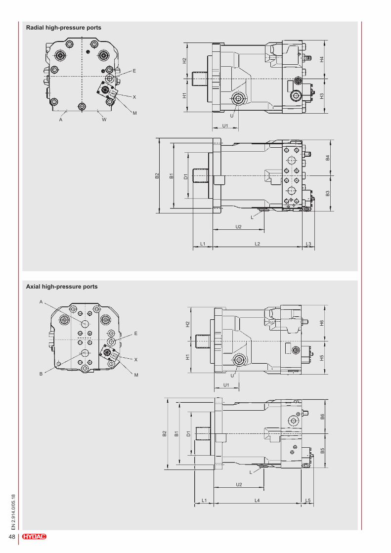
5.3 MPV200
Nominal size 55 75 105 135 165 210 280
D1 [mm] 127 152.4 165.1
B1 [mm] 181 228.6 224.5
B2 [mm] 208 258 269
B3 [mm] 86 95 96 108 125 134 156
B4 [mm] 95 96 108 125 134 156
B5 [mm] 86 95 96 108 125 * *B6 [mm] 85 95 96 108 125 * *B7 [mm]Withelectricoverridecontrol
– 180 181 193 210 * *B8 [mm]Withelectricoverridecontrol
– 180 181 193 210 * *H1 [mm] 80 86 91 98 98 135
H2 [mm] 83 93 99 103 98 135
H3 [mm] 84 93 95 108 120 134 151.5
H4 [mm] 90 105 106 114 132 133 152.5
H5 [mm] 84 93 96 107 118 * *H6 [mm] 90 105 114 132 * *H7 [mm]Withelectricoverridecontrol
– 88 102.5 * *H8 [mm]Withelectricoverridecontrol
– 92 77.5 * *L1 [mm] 41 56 75
L2 [mm] 212 226 247 270 314 336 381
L3 [mm] controlHydraulic 33 5 5 8
Electrical 75 58 55 59
L4 [mm] 217 231 252 275 305 * *
L5 [mm] controlHydraulic 18 5 * *Electrical 70 58 * *
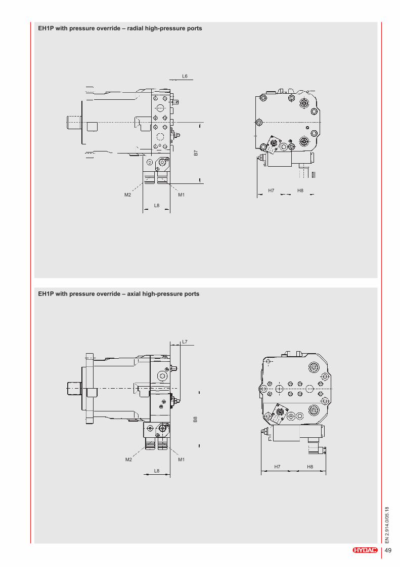
L6 [mm]Withelectricoverridecontrol
– 33 32.5 * *L7 [mm]Withelectricoverridecontrol
– 28 32.5 * *L8 [mm]Withelectricoverridecontrol
– 80 80.5 * *U1 [mm] *
U2 [mm] *
L, U M22x1.5 M27x2 M33x2
EPortforexternalservopressuresupply
M14x1.5
XPortforhydrauliccontrol
M14x1.5
M, M1Solenoidforelectricalcontrol
Seesection3.4MPV200
M2Solenoidsforsignalselectionforpressureregulator
Seesection3.4MPV200
A Seesection5.5Connections
B Seesection5.5Connections
*Productversion/dimensionsonrequest
Threadedconnectionmetricinacc.withISO6149-1.FasteningthreadattheSAEhigh-pressureports metricinacc.withISO261.Cylinderheadscrewsinacc.withISO4762.Additionalthreads,dimensionsanddesignswith speedsensoronrequest.MountingflangetoISO6162-2.
Threadedconnection,metric inacc.withISO6149-1
48
EN
2.9
14.0
/05.
18
Radial high-pressure ports
H2 H4
H1
H3
U
U1
E
X
MWA
B2
B1
D1
B3
B4
L1 L3
L
U2
L2
H2 H6
H1
H5
U
U1
E
X
MB
A
B2
B1
D1
B5
B6
L1 L5
L
U2
L4
Axial high-pressure ports
49
EN
2.9
14.0
/05.
18
EH1P with pressure override – radial high-pressure ports
EH1P with pressure override – axial high-pressure ports
H8H7
H8H7
B7
B8
L8
L8
L6
L7
M1
M1
M2
M2

50
EN
2.9
14.0
/05.
18
5.4 MPR200
Nominal size 75 105 135 165 210 280
D1 [mm] 127 152.4 165.1 *B1 [mm] 181 228.6 224.5 *B2 [mm] 208 256 269 *B3 [mm]Secondaryreliefvalve
without 95 99 108 – 134 *with 135 136 140 – 134 *
B4 [mm]Secondaryreliefvalve
without 95 105 108 – 134 *with 12 105 114 – 134 *
B5 [mm]Secondaryreliefvalve
without 95 99 108 * *with 135 139 141 148 * *
B6 [mm] 102 105 114 125 * *B7 [mm] 62 46 * *B8 [mm] 78 * *B9 [mm] 103 108 *H1 [mm] 86 91 96 98 135.5 *H2 [mm] 93 99 100 105 135.5 *H3 [mm] 93 98 108 – 134 *H4 [mm] 102 110 – 133.5 *H5 [mm] 56 *H6 [mm] 91 96 107 118 134 *H7 [mm] 102 107 109 125 133.5 *H8 [mm] 81 *L1 [mm] 56 75 *L2 [mm] 229 247 270 – 336 *L3 [mm] 231 252 275 304 – *L4 [mm] 53 *L5 [mm]regulatorwithelectricmax.displacementoverrideandsignalselectionforpressureregulator
80 *
U1 [mm] *
U2 [mm] *
L, U M22x1.5 M27x2 *X1 Portforhydraulicandpneumaticmax.displacementoverride
M14x1.5 *
M1 Solenoidforelectricmax.displacementoverride
Seesection3.5MPR200
M2 solenoidforsignalselectionforpressureregulator
Seesection3.5MPR200
A Seesection5.5Connections
B Seesection5.5Connections
*Productversion/dimensionsonrequest
Threadedconnectionmetricinacc.withISO6149-1.FasteningthreadattheSAEhigh-pressureports metricinacc.withISO261.Cylinderheadscrewsinacc.withISO4762.Additionalthreads,dimensionsanddesignswith speedsensoronrequest.MountingflangetoISO6162-2.
Threadedconnection,metric inacc.withISO6149-1

51
EN
2.9
14.0
/05.
18
H2 H7
H5
L4
B7 B8
H1
H6
U1
U
X1
A
W
B2
B1
D1
B5
B6
L1
L5 M1M2
LU2
L3
Radial high-pressure ports
Axial high-pressure ports
H2 H4
H5
L4
B7 B8
H1
H3
U
U1
X1
B2
B1
D1
B3
B4
H8
L1
B9a
B
L
U2
L2
52
EN
2.9
14.0
/05.
18
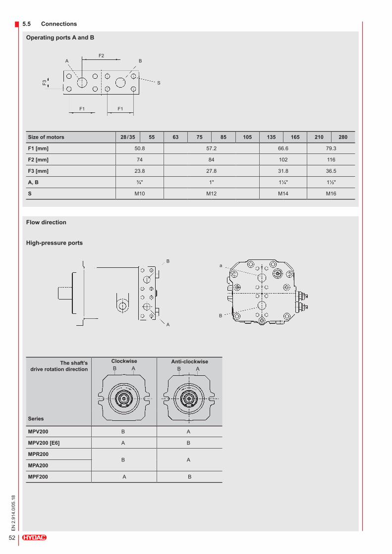
Operating ports A and B
Flow direction
High-pressure ports
5.5 Connections
Size of motors 28 / 35 55 63 75 85 105 135 165 210 280
F1 [mm] 50.8 57.2 66.6 79.3
F2 [mm] 74 84 102 116
F3 [mm] 23.8 27.8 31.8 36.5
A, B ¾" 1ʺ 1¼" 1½"
S M10 M12 M14 M16
The shaft’s drive rotation direction
ClockwiseB A
Anti-clockwiseB A
Series
MPV200 B A
MPV200 [E6] A B
MPR200B A
MPA200
MPF200 A B
F2
F1 F1
F3
B
S
A
B
A
B
a

53
EN
2.9
14.0
/05.
18
NOTES

54
EN
2.9
14.0
/05.
18
NOTES

55
EN
2.9
14.0
/05.
18
NOTES
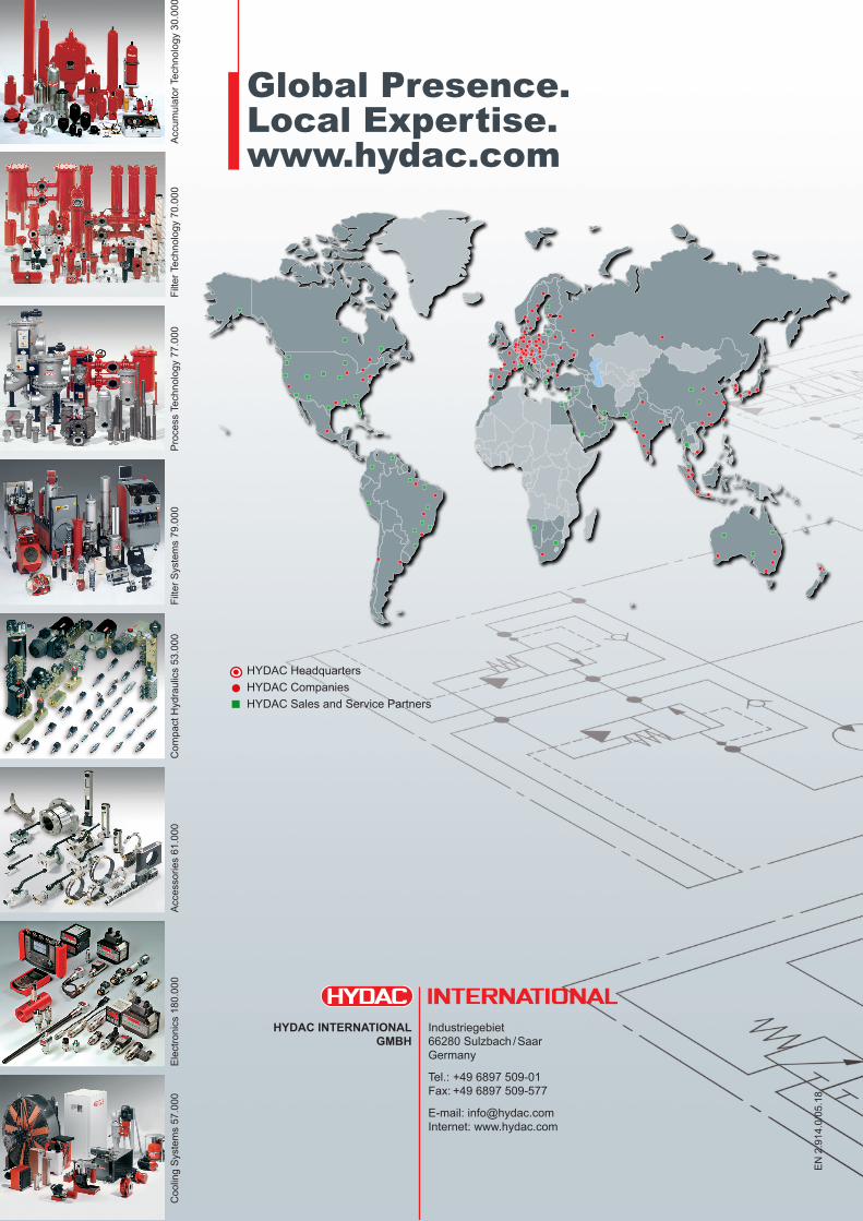
Global Presence.Local Expertise.www.hydac.com
EN
2.9
14.0
/05.
18
HYDACHeadquartersHYDACCompaniesHYDACSalesandServicePartners
CoolingSystems57.000
HYDAC INTERNATIONAL Industriegebiet GMBH 66280Sulzbach/Saar Germany
Tel.:+496897509-01 Fax:+496897509-577
E-mail:[email protected] Internet:www.hydac.com
ProcessTechnology77.000
FilterTechnology70.000
Accum
ulatorTechnology30.000
Com
pactHydraulics53.000
FilterS
ystems79.000
Accessories61.000
Electronics180.000