hydrachem operation manual - paragontrailer.com operati… · pre-initial start up check list 1....
TRANSCRIPT
HydraCHEM Operation ManualSeptember 21, 2016
Installation and
Operation Manual

Congratulationson your new Paragon purchase
2
3
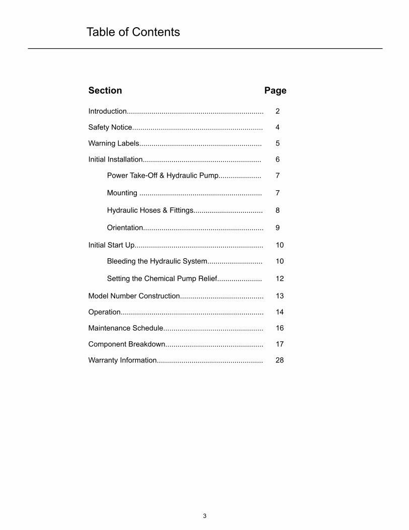
Table of Contents
Section! ! ! ! ! ! ! ! Page
Introduction................................................................... 2
Safety Notice................................................................ 4
Warning Labels............................................................ 5
Initial Installation.......................................................... 6
! Power Take-Off & Hydraulic Pump.....................! 7
! Mounting ............................................................! 7
! Hydraulic Hoses & Fittings..................................! 8
! Orientation...........................................................! 9
Initial Start Up............................................................... 10
! Bleeding the Hydraulic System...........................! 10
! Setting the Chemical Pump Relief......................! 12
Model Number Construction......................................... 13
Operation...................................................................... 14
Maintenance Schedule................................................. 16
Component Breakdown................................................ 17
Warranty Information.................................................... 28
This manual is designed to be read to its entirety prior to installation or operation of this product.
Do NOT install or operate prior to reading this manual completely - injury or property damage can occur.
Use adequate protection and safety equipment while preforming the steps indicated in this manual.
Protect against hazards involved during the installation and operation of this equipment.
Failure to read this manual completely or heed these warnings could result in serious bodily injury or loss of life.
For equipment covered specifically or indirectly in this operation manual, it is important that all personnel observe the appropriate safety precautions to minimize the changes of injury.
DO NOT....DO NOT....
- Attempt to install equipment with the truck engine running
- Allow the truck engine to be started while personnel are under the vehicle or working on any equipment
- Place any body part over any pneumatic ( or hydraulic ) leak or outlet while the equipment is in operation
- Engage or disengage driven equipment by hand from under the vehicle while the engine is running
- Use tools or equipment that are in poor or non-working condition
- Remove, obscure, cover, or paint over any warning labels
DO....DO....
- Read and Understand all original equipment manufacturers manuals before installation or operation of any equipment installed in the HydraCHEM
- Follow all safety rules and regulations as it applies to the equipment provided
- Immobilize truck wheels with suitable chocks before working under the truck
- Block any raised equipment before working on or under the equipment
- Obtain proper training on tools and equipment that are required
- Ensure all tools and components are in good working condition
- Use all tools and equipment for its intended purpose only
- Repair any leaks promptly
- Remain a safe distance away from any moving components during operation
4
Safety Notice
5
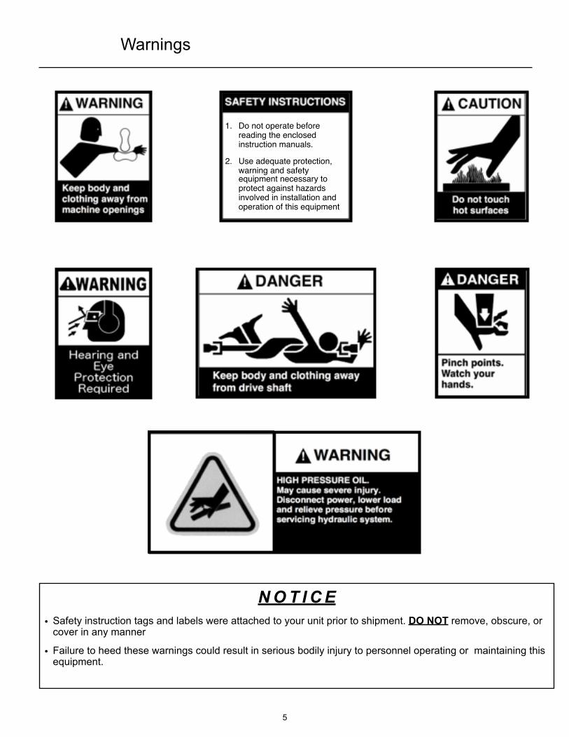
N O T I C E• Safety instruction tags and labels were attached to your unit prior to shipment. DO NOT remove, obscure, or
cover in any manner
• Failure to heed these warnings could result in serious bodily injury to personnel operating or maintaining this equipment.
1. Do not operate before reading the enclosed instruction manuals.
2. Use adequate protection, warning and safety equipment necessary to protect against hazards involved in installation and operation of this equipment
Warnings
6
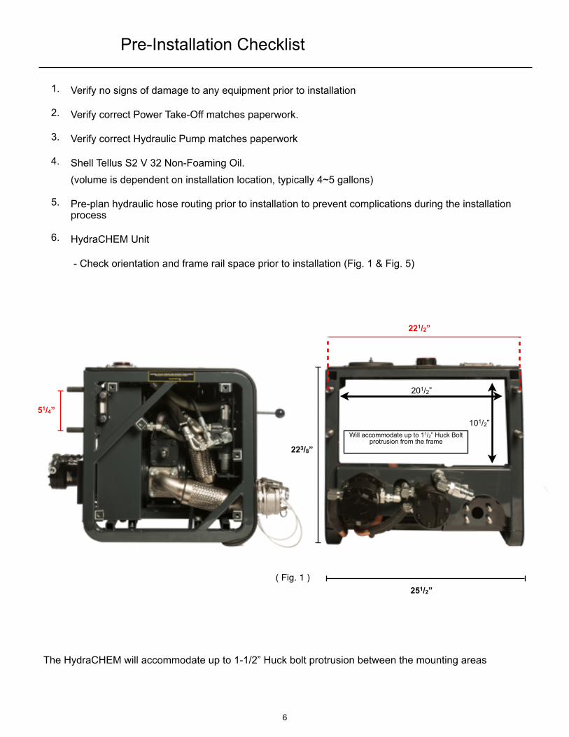
1. Verify no signs of damage to any equipment prior to installation
2. Verify correct Power Take-Off matches paperwork.
3. Verify correct Hydraulic Pump matches paperwork
4. Shell Tellus S2 V 32 Non-Foaming Oil.(volume is dependent on installation location, typically 4~5 gallons)
5. Pre-plan hydraulic hose routing prior to installation to prevent complications during the installation process
6. HydraCHEM Unit
- Check orientation and frame rail space prior to installation (Fig. 1 & Fig. 5)
201/2”
101/2”Will accommodate up to 11/2” Huck Bolt
protrusion from the frame223/8”
251/2”
221/2”
51/4”
( Fig. 1 )
Pre-Installation Checklist
The HydraCHEM will accommodate up to 1-1/2” Huck bolt protrusion between the mounting areas
7
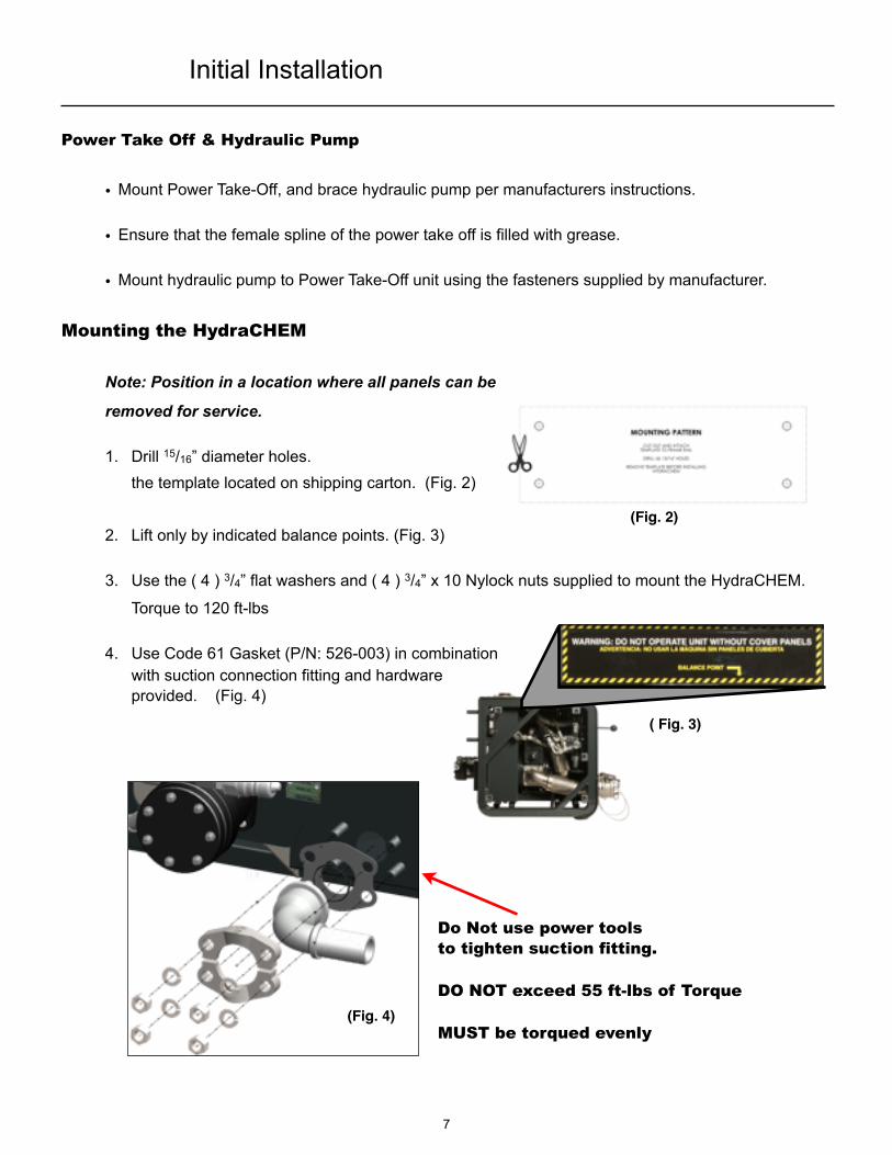
Power Take Off & Hydraulic Pump
• Mount Power Take-Off, and brace hydraulic pump per manufacturers instructions.
• Ensure that the female spline of the power take off is filled with grease.
• Mount hydraulic pump to Power Take-Off unit using the fasteners supplied by manufacturer.
Mounting the HydraCHEM
Note: Position in a location where all panels can be
removed for service.
1. Drill 15/16” diameter holes. the template located on shipping carton. (Fig. 2)
2. Lift only by indicated balance points. (Fig. 3)
3. Use the ( 4 ) 3/4” flat washers and ( 4 ) 3/4” x 10 Nylock nuts supplied to mount the HydraCHEM.
Torque to 120 ft-lbs
4. Use Code 61 Gasket (P/N: 526-003) in combination with suction connection fitting and hardware provided. (Fig. 4)
(Fig. 2)
(Fig. 4)
Initial Installation
Do Not use power tools to tighten suction fitting.
DO NOT exceed 55 ft-lbs of Torque
MUST be torqued evenly
( Fig. 3)

11/4” Suction Line(Type 100R4 & 28”hg vacuum)
3/4” High Pressure Line(Type 100R2 & 2500 psi wp)
8
Hydraulic Hoses & Fittings
1. DO NOT use thread tape or pipe dope on hydraulic NPT connections, this will
contaminate the hydraulic system. Use a hydraulic sealant for all NPT connections
(Locktite number 545 or similar).
2. High Pressure and Suction hoses are customer supplied, and will need to be measured
to fit according to system drawings and installation locations
3. High pressure hoses must have a pressure rating equal or higher than the hydraulic
system relief valve setting of 2500 psi
4. The suction hose must be capable of operating in 28” Hg vacuum service and routed
below the hydraulic motors (Fig. 5)
5. Attach Code 61 Gasket (P/N: 526-003, Fig. 4) in combination with suction connection
fitting and hardware provided before installing the Suction Hose.
Initial Installation / Continued

Orientation• The Quick Release Coupler is oriented for drivers side installation (standard
configuration) or can be rotated for Passenger Side installation.
• The Suction line can be rotated as needed and should run below the hydraulic motors in either Driver Side or Passenger Side orientation. (Fig. 5)
• Ensure all hoses are supported and the suction line is routed below the hydraulic motors.
• Do not allow the Suction Hose to pull on the HydraCHEM, it must be supported and not allowed to hang.
CAUTION: DO NOT Allow hydraulic hoses to rest on the hydraulic motors as this can cause damage to hoses over time
9
Initial Installation / Continued
Pre-Initial Start Up Check List
1. Check the P40 Oil level after installation and before bleeding the hydraulic system. (Fig. 6)
2. Ensure the Air lever is in the “Vent” position.
3. Ensure all grommets are in place.
4. Ensure all covers are in place prior to operation.
5. Ensure all D-Ring clips are fastened in place.
6. Ensure the hydraulic control handle is in the neutral position.
7. Ensure all dust caps/plugs are in place.
8. Double check all filter caps and fill caps to ensure they are tight.
FULLADD
( Fig. 6 )
High Pressure Line from Hydraulic Pump
Suction Line to Hydraulic Pump
Drivers Side installation Passengers Side installation
(Fig. 5)

Bleeding the Hydraulic System
1. Remove red hydraulic fill cap. (Fig. 7)
2. Use Shell Tellus S2 V 32 non-foaming hydraulic oil.
3. Fill HydraCHEM with hydraulic fluid until sight glass reaches half way.
It is recommended that the oil be filtered while being added. (a clean paint filter will suffice)
4. Replace fill cap.
5. Check all hoses and connections for leaks.
Installation must be free from leaks before continuing.
6. Start the truck engine.
7. Engage the PTO. (See PTO Owner’s Manual)
8. Run for 5 - 10 seconds to eliminate air from the system.
9. Remove Dust Caps from the chemical pump and slowly engage the chemical pump to remove air from this circuit, do not run for longer than 20 seconds dry.
10. Remove Universal Pneumatic Connector Plug and slowly engage the P40 to remove air from this circuit.
11. Disengage PTO.
12. Check hydraulic fluid level, fill back to 1/2 way on sight glass, and repeat steps 6-10 as needed.
13. Check for any signs of leaks, removal of the side panels is required.
14. Re-check oil level.
10
Initial Start Up

11
Hydraulic Filter Cap
Hydraulic Oil Fill Cap P40 Air Filter Cover
P40 Oil Fill Cap
P40 Oil Sight Glass
Hydraulic Oil Sight Glass
Universal Pneumatic Connector Plug
(Fig. 7)
Initial Start Up / Continued
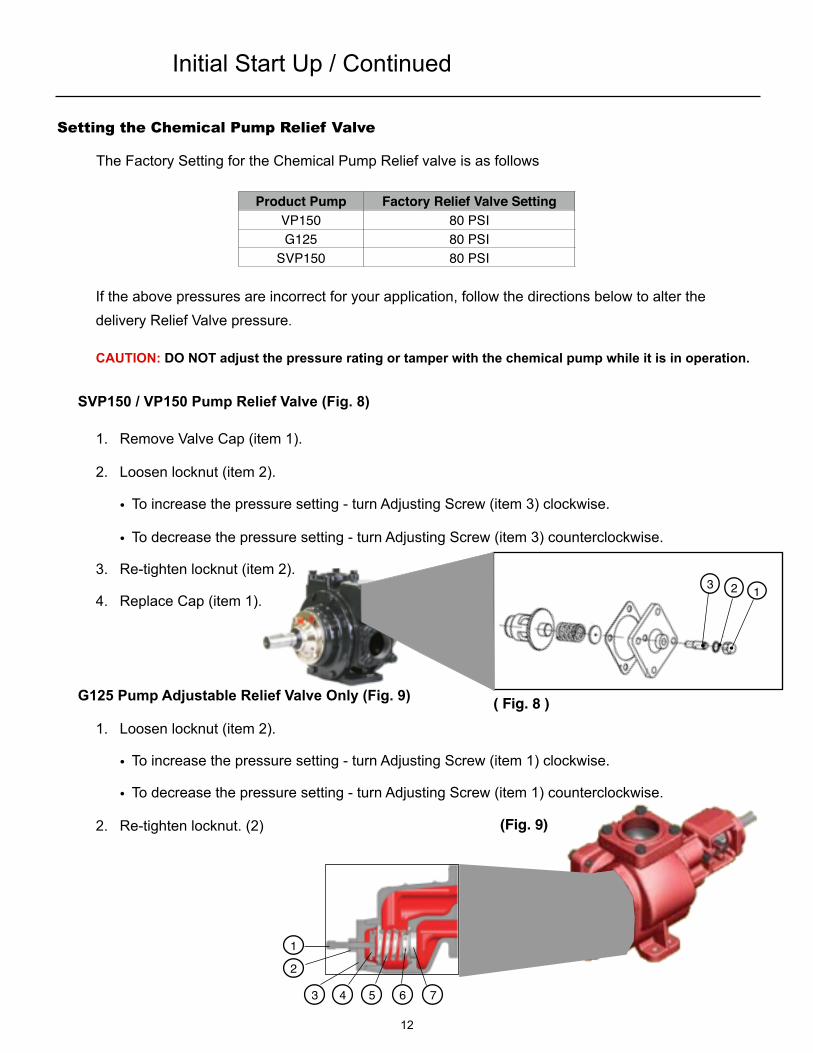
Setting the Chemical Pump Relief Valve
The Factory Setting for the Chemical Pump Relief valve is as follows
Product Pump Factory Relief Valve SettingVP150 80 PSIG125 80 PSI
SVP150 80 PSI
If the above pressures are incorrect for your application, follow the directions below to alter the delivery Relief Valve pressure.
CAUTION: DO NOT adjust the pressure rating or tamper with the chemical pump while it is in operation.
SVP150 / VP150 Pump Relief Valve (Fig. 8)
1. Remove Valve Cap (item 1).
2. Loosen locknut (item 2).
• To increase the pressure setting - turn Adjusting Screw (item 3) clockwise.
• To decrease the pressure setting - turn Adjusting Screw (item 3) counterclockwise.
3. Re-tighten locknut (item 2).
4. Replace Cap (item 1).
G125 Pump Adjustable Relief Valve Only (Fig. 9)
1. Loosen locknut (item 2).
• To increase the pressure setting - turn Adjusting Screw (item 1) clockwise.
• To decrease the pressure setting - turn Adjusting Screw (item 1) counterclockwise.
2. Re-tighten locknut. (2)
123
12
1
2
3 4 5 6 7
( Fig. 8 )
(Fig. 9)
Initial Start Up / Continued
13
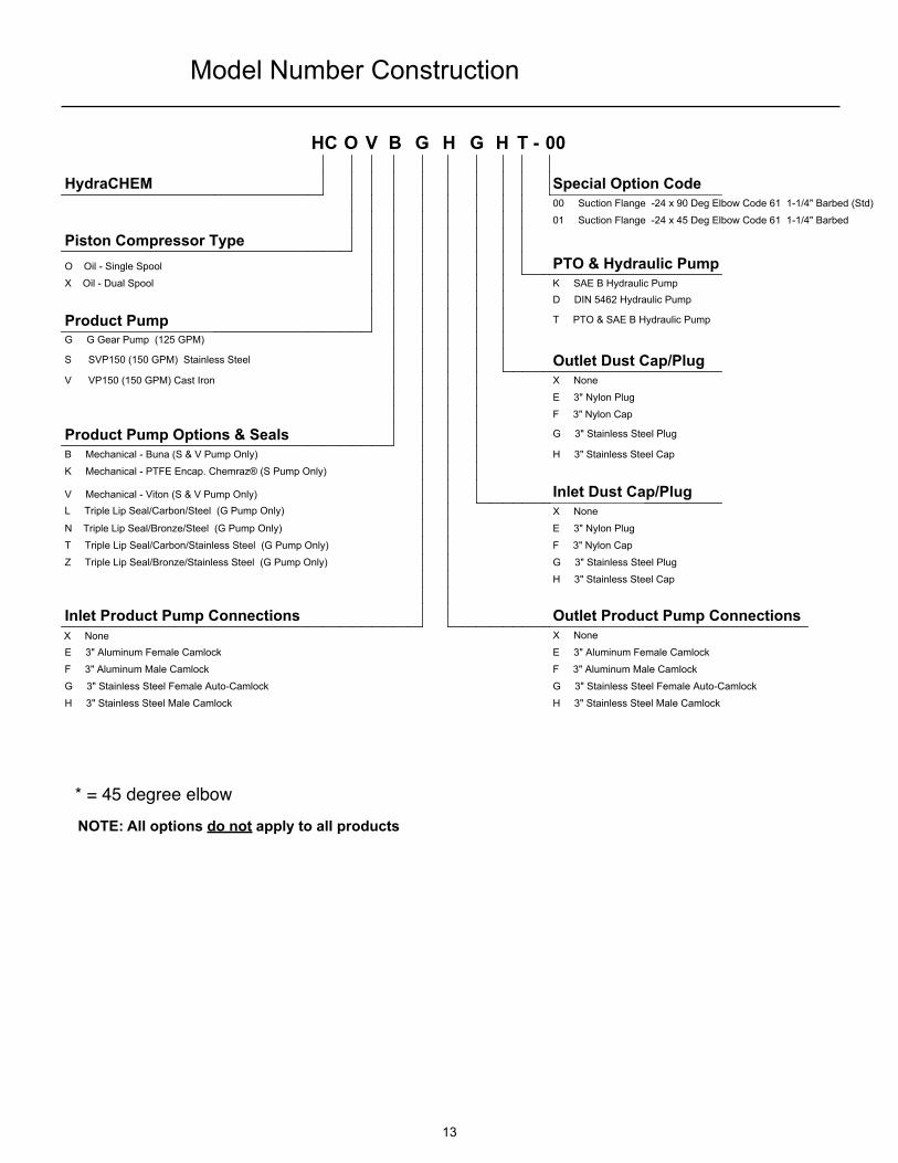
NOTE: All options do not apply to all products
Model Number Construction
* = 45 degree elbow
*
X None
HC O V B G H G H T - 00
HydraCHEM Special Option Code00 Suction Flange -24 x 90 Deg Elbow Code 61 1-1/4" Barbed (Std)
01 Suction Flange -24 x 45 Deg Elbow Code 61 1-1/4" Barbed
Piston Compressor TypeO Oil - Single Spool PTO & Hydraulic PumpX Oil - Dual Spool K SAE B Hydraulic Pump
D DIN 5462 Hydraulic Pump
Product Pump T PTO & SAE B Hydraulic Pump
G G Gear Pump (125 GPM)
S SVP150 (150 GPM) Stainless Steel Outlet Dust Cap/PlugV VP150 (150 GPM) Cast Iron X None
E 3" Nylon Plug
F 3" Nylon Cap
Product Pump Options & Seals G 3" Stainless Steel Plug
B Mechanical - Buna (S & V Pump Only) H 3" Stainless Steel Cap
K Mechanical - PTFE Encap. Chemraz® (S Pump Only)
V Mechanical - Viton (S & V Pump Only) Inlet Dust Cap/PlugL Triple Lip Seal/Carbon/Steel (G Pump Only) X None
N Triple Lip Seal/Bronze/Steel (G Pump Only) E 3" Nylon Plug
T Triple Lip Seal/Carbon/Stainless Steel (G Pump Only) F 3" Nylon Cap
Z Triple Lip Seal/Bronze/Stainless Steel (G Pump Only) G 3" Stainless Steel Plug
H 3" Stainless Steel Cap
Inlet Product Pump Connections Outlet Product Pump ConnectionsX None
E 3" Aluminum Female Camlock E 3" Aluminum Female Camlock
F 3" Aluminum Male Camlock F 3" Aluminum Male Camlock
G 3" Stainless Steel Female Auto-Camlock G 3" Stainless Steel Female Auto-Camlock
H 3" Stainless Steel Male Camlock H 3" Stainless Steel Male Camlock
14
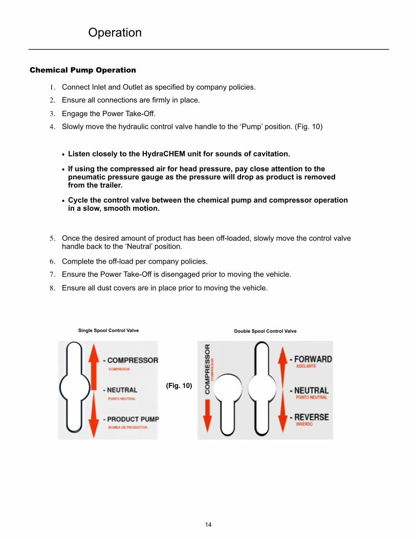
Chemical Pump Operation
1. Connect Inlet and Outlet as specified by company policies.
2. Ensure all connections are firmly in place.
3. Engage the Power Take-Off.
4. Slowly move the hydraulic control valve handle to the ‘Pump’ position. (Fig. 10)
• Listen closely to the HydraCHEM unit for sounds of cavitation.
• If using the compressed air for head pressure, pay close attention to the pneumatic pressure gauge as the pressure will drop as product is removed from the trailer.
• Cycle the control valve between the chemical pump and compressor operation in a slow, smooth motion.
5. Once the desired amount of product has been off-loaded, slowly move the control valve handle back to the ‘Neutral’ position.
6. Complete the off-load per company policies.
7. Ensure the Power Take-Off is disengaged prior to moving the vehicle.
8. Ensure all dust covers are in place prior to moving the vehicle.
Single Spool Control Valve Double Spool Control Valve
(Fig. 10)
Operation

15
Compressor Operation
1. Connect the air delivery hose to the HydraCHEM Universal Pneumatic Connection fitting and to the trailer.
• If using compressed air for head pressure, see Chemical Pump Operation
2. Ensure the air flow control valve is in the “Vent” position.
3. Ensure all connections are firmly in place.
4. Engage the Power Take-Off.
5. Slowly move the hydraulic control valve handle fully to the ‘Compressor’ position. (Fig. 10)
6. Slowly move the air flow control valve to the ‘Operation’ position.
• The air flow control valve can be used to bleed off excess pressure and air flow, simply crack the valve towards the vent position as desired. Do not exceed tank pressure rating or 36 psi whichever is lower.
7. Once the desired amount of product has been off-loaded, slowly move the air flow control valve handle back to the ‘Vent’ position.
8. Slowly move the control valve handle back to the ‘Neutral’ position.
9. Wrap-up the off-load per company policies.
CAUTION: The air delivery line may still be under pressure wait for pressure to return to zero.
10. Ensure all dust covers are in place prior to moving the vehicle.
11. Ensure the Power Take-Off is disengaged prior to moving the vehicle.
Trailer Chemical Outlet
All labels are for reference onlyActual locations may vary
HydraCHEM Universal Pneumatic Connection Fitting
Trailer Universal Pneumatic Connection Fitting
Storage Tank Inlet
Operation / Continued

16
Interval ItemItemItem
Daily
P40 Air CompressorP40 Air CompressorP40 Air CompressorCheck Oil level before operating the compressorCheck Oil level before operating the compressor
Hydraulic SystemHydraulic SystemHydraulic SystemCheck Oil level before operation.** Correct level is to the center of the sight glass when hydraulic system is cold, and not in operation.
Check Oil level before operation.** Correct level is to the center of the sight glass when hydraulic system is cold, and not in operation.
WeeklyGeneralGeneralGeneral
Visually inspect the system. (High pressure and suction hose, fittings, and mounting bolts)Visually inspect the system. (High pressure and suction hose, fittings, and mounting bolts)
3 MonthsGeneralGeneralGeneral
Inspect hydraulic motor couplings for damage, replace as neededInspect hydraulic motor couplings for damage, replace as neededHydraulic SystemHydraulic SystemHydraulic System
Change Hydraulic Oil Filter** An oil analysis is recommended to determine the lifetime of the oil remaining
Change Hydraulic Oil Filter** An oil analysis is recommended to determine the lifetime of the oil remaining
Chemical Pump MaintenanceChemical Pump MaintenanceChemical Pump MaintenanceLubricate ball bearings.
Recommended grease: Mobile Grease XHP 222 Lubricate ball bearings.
Recommended grease: Mobile Grease XHP 222
6 MonthsP40 Air CompressorP40 Air CompressorP40 Air Compressor
Change OilChange OilChange Air Filter ElementChange Air Filter Element
Hydraulic SystemHydraulic SystemHydraulic SystemChange Hydraulic Oil
** An oil analysis is recommended to determine the lifetime of the oil remainingChange Hydraulic Oil
** An oil analysis is recommended to determine the lifetime of the oil remaining
Power Take-Off UnitPower Take-Off UnitGrease the Power Take-Off / Hydraulic Pump SplinesGrease the Power Take-Off / Hydraulic Pump Splines
Yearly
GeneralGeneralGeneral
Inspect Chemical Pump for wear ( replace components as needed )Inspect Hydraulic Pump splines for wearInspect Chemical Pump for wear ( replace components as needed )Inspect Hydraulic Pump splines for wear
P40 Air CompressorP40 Air CompressorP40 Air CompressorChange Relief ValveChange Relief Valve
Maintenance Schedule
After use cleaning and lubrication is required to prevent pump components from seizing.
To lubricate the product pump, remove both inlet and outlet dust covers, spray an aerosol lubricant into the pump inlet while in operation, and watch for vapors on the outlet side of the pump.
NOTE: Always check chemical compatibility before introducing the lubricant Continue for 30 seconds or until vapors are seen exiting the outlet.
Annual service interval kit 621-032 available - check with your local dealer for pricing621-032 contains: Hyd. Filter, Air Filter, Compressor Relief Valve, and Compressor oil

3
7
1
2
8
4
5
6
17
Assembly Description Page
1 Hydraulic Tank Assembly 18
2 P40 Assembly 19
3 Frame Pre-Assembly 20
4Directional Control Valve Assembly
214Double Spool Directional Control Valve Assembly
21
5 Heat Exchanger Assembly 22
6 Cover Panel Assembly 23
7 Lower Front Mount Assembly 24
8Pump and Pipe Work Assembly (SVP150/VP150) 25
8Pump and Pipe Work Assembly (G125) 26
Component Breakdown
18
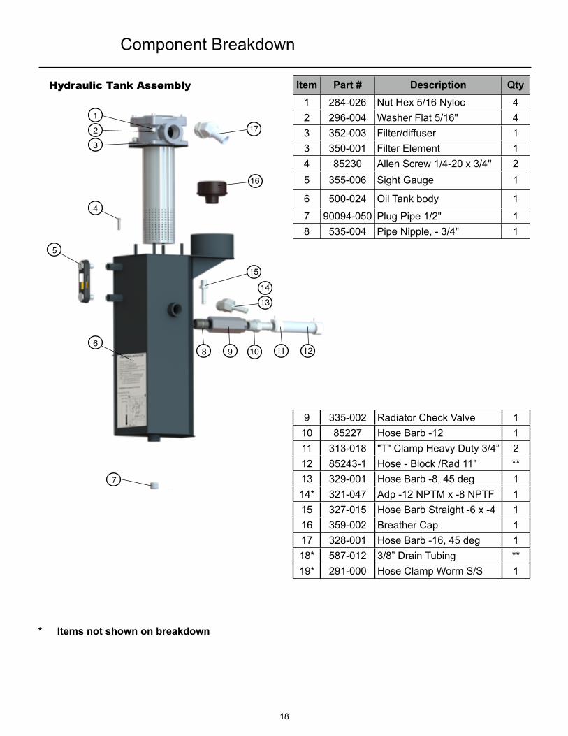
9 335-002 Radiator Check Valve 110 85227 Hose Barb -12 111 313-018 "T" Clamp Heavy Duty 3/4” 212 85243-1 Hose - Block /Rad 11" **13 329-001 Hose Barb -8, 45 deg 114* 321-047 Adp -12 NPTM x -8 NPTF 115 327-015 Hose Barb Straight -6 x -4 116 359-002 Breather Cap 117 328-001 Hose Barb -16, 45 deg 118* 587-012 3/8” Drain Tubing **19* 291-000 Hose Clamp Worm S/S 1
1
32
4
5
6
7
8 9 10 11 12
1314
15
16
17
Hydraulic Tank Assembly
* Items not shown on breakdown
Component Breakdown
Item Part # Description Qty1 284-026 Nut Hex 5/16 Nyloc 42 296-004 Washer Flat 5/16" 43 352-003 Filter/diffuser 13 350-001 Filter Element 14 85230 Allen Screw 1/4-20 x 3/4'' 25 355-006 Sight Gauge 1
6 500-024 Oil Tank body 1
7 90094-050 Plug Pipe 1/2" 18 535-004 Pipe Nipple, - 3/4" 1
1
3
2
45
6
7
8 9 10 11
12
13
1415
19
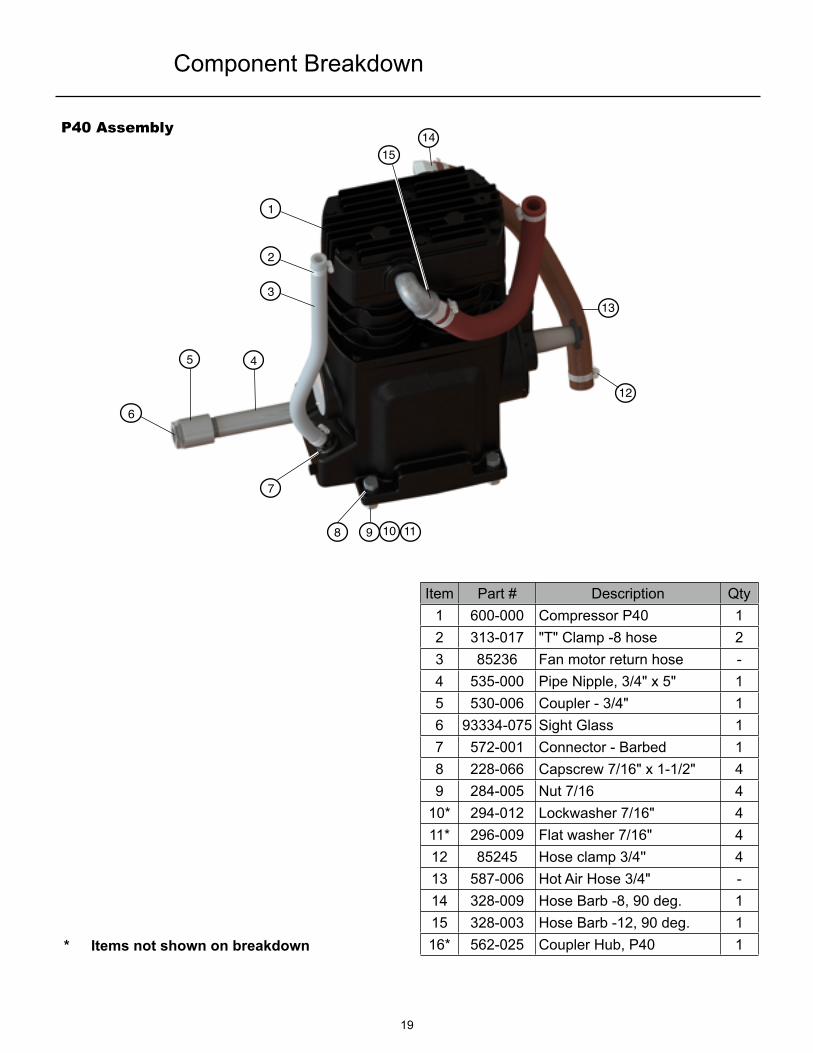
P40 Assembly
Component Breakdown
* Items not shown on breakdown
Item Part # Description Qty1 600-000 Compressor P40 12 313-017 "T" Clamp -8 hose 23 85236 Fan motor return hose -4 535-000 Pipe Nipple, 3/4" x 5" 15 530-006 Coupler - 3/4" 16 93334-075 Sight Glass 17 572-001 Connector - Barbed 18 228-066 Capscrew 7/16" x 1-1/2" 49 284-005 Nut 7/16 4
10* 294-012 Lockwasher 7/16" 411* 296-009 Flat washer 7/16" 412 85245 Hose clamp 3/4'' 413 587-006 Hot Air Hose 3/4" -14 328-009 Hose Barb -8, 90 deg. 115 328-003 Hose Barb -12, 90 deg. 116* 562-025 Coupler Hub, P40 1
20
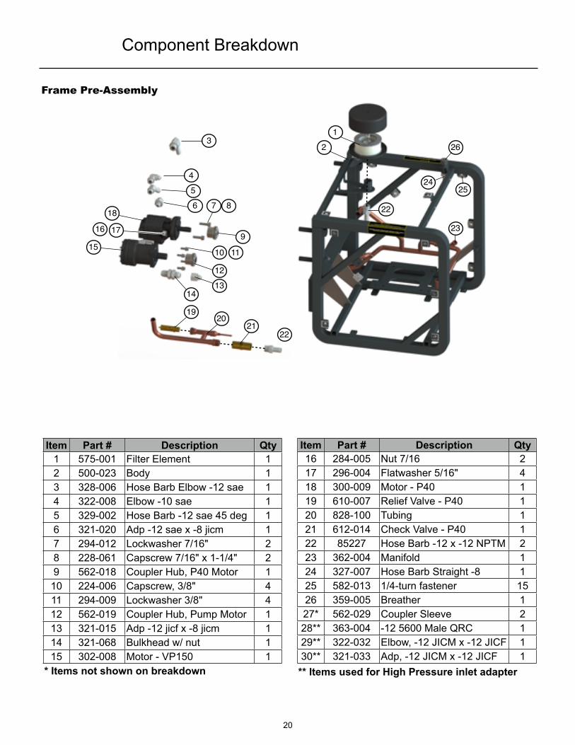
Frame Pre-Assembly
12
3
456 7 8
9
12
10 11
1314
15
16 17
18
1920
2122
22
23
2425
26
Component Breakdown
* Items not shown on breakdown
Item Part # Description Qty16 284-005 Nut 7/16 217 296-004 Flatwasher 5/16" 418 300-009 Motor - P40 119 610-007 Relief Valve - P40 120 828-100 Tubing 121 612-014 Check Valve - P40 122 85227 Hose Barb -12 x -12 NPTM 223 362-004 Manifold 124 327-007 Hose Barb Straight -8 125 582-013 1/4-turn fastener 1526 359-005 Breather 127* 562-029 Coupler Sleeve 228** 363-004 -12 5600 Male QRC 129** 322-032 Elbow, -12 JICM x -12 JICF 130** 321-033 Adp, -12 JICM x -12 JICF 1
Item Part # Description Qty1 575-001 Filter Element 12 500-023 Body 13 328-006 Hose Barb Elbow -12 sae 14 322-008 Elbow -10 sae 15 329-002 Hose Barb -12 sae 45 deg 16 321-020 Adp -12 sae x -8 jicm 17 294-012 Lockwasher 7/16" 28 228-061 Capscrew 7/16" x 1-1/4" 29 562-018 Coupler Hub, P40 Motor 1
10 224-006 Capscrew, 3/8" 411 294-009 Lockwasher 3/8" 412 562-019 Coupler Hub, Pump Motor 113 321-015 Adp -12 jicf x -8 jicm 114 321-068 Bulkhead w/ nut 115 302-008 Motor - VP150 1
** Items used for High Pressure inlet adapter

21
Directional Control Valve Assembly
1
2 3
4
5
67 8
9
12
10 11
13
1516
1718
14
14
Component Breakdown
Item Part # Description Qty15 322-017 Elbow -12 116 321-072 Adp -8 JICM x -8 JICF 117 320-011 Tee -8 118 361-023 Hose Assy HP 119 321-031 Adp -8 SAE x -8 JICM 320 334-018 Double Spool Control Valve 121 508-047 Dbl Spool DCV Bracket 122 228-010 Capscrew 5/16” 423 294-008 Lockwasher 5/16” 424 85234 Hex Nut 5/16” 425 321-018 Adp -10SAE x -8 JICM 126 327-018 Hose Barb -12 x -10SAE 127* 322-033 Elbow -8JICM x -8 JICF 128 508-047 Single Spool DCV Bracket 1
Item Part # Description Qty1 361-022 Hose Assy 2(3)2 321-018 Adp -10 SAE x -8 JICM 23 313-018 "T" Clamp -12 24 85243-1 Hose - Low Pressure -5 328-006 Hose Barb -12 - 90 deg. 16 334-008 Single Spool Control Valve 17 224-001 Capscrew 1/4-28 38 284-003 Nut 1/4" 39 284-024 Nut 1/4" 2
10 296-002 Flatwasher 1/4" 211 294-003 Lockwasher 1/4" 712 527-010 Handle - Straight 1(0)13 527-016 Phenolic Ball 1(0)14 85230 Allen Screw 1/4-20 4
19
26 25
20
21
22
23 24
Note: () contains qty’s needed for a double spool version (where different)* Not shown
28

22
1 2
45
4
3 6 7 8
9
10
11
12 13 14 15
9
1617
181920
13 15 16
21
2223
Heat Exchanger Assembly
Component Breakdown
Item Part # Description Qty14 296-002 Flatwasher 1/4" 215 294-003 Lockwasher 1/4" 916 85230 Allen screw 1/4-20 717 370-003 Heat Exchanger 118 328-005 Hose Barb -16, 90 deg. 119 313-021 "T" Clamp -16 hose 220 85244 Hose Filter/Radiator -21 85218 Hose Barb -8, 90deg. 122 313-017 "T" Clamp -8 hose 223 85236 Fan Motor Return Hose -24* 352-006 Fan Motor in-line filter 125* 322-001 Elb. -8 SAEM x -8 JICF 126* 321-075 Adp. -8 SAEM x -4 SAEF 1* Items not shown on breakdown* Items not shown on breakdown* Items not shown on breakdown* Items not shown on breakdown
Item Part # Description Qty1 361-000 Hose Assy SCV to DCV 12 322-027 Fan Flow control 13 300-007 Fan Motor 14 508-064 Bracket - heat shield 15 572-000 Fiberglass Heat Shield 15 572-003 Aluminum Heat Shield 16 85234 Nut 5/16'' 47 294-008 Lockwasher 5/16" 48 228-010 Capscrew 5/16" 49 85258 Retaining ring 2
10 570-000 Trim -11 508-049 Fan bracket 112 507-001 Fan 113 284-024 Nut 1/4" 6
1
2 5
78
12
10
11
14515
19
20
21
34
18
23
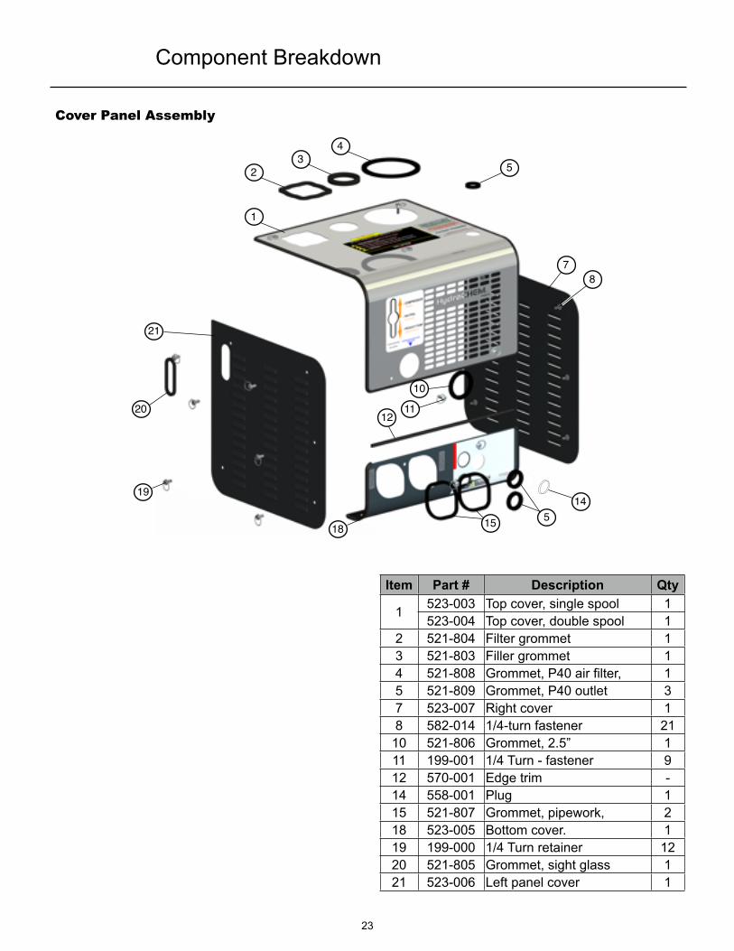
Cover Panel Assembly
Component Breakdown
Item Part # Description Qty
1 523-003 Top cover, single spool 11523-004 Top cover, double spool 1
2 521-804 Filter grommet 13 521-803 Filler grommet 14 521-808 Grommet, P40 air filter, 15 521-809 Grommet, P40 outlet 37 523-007 Right cover 18 582-014 1/4-turn fastener 21
10 521-806 Grommet, 2.5” 111 199-001 1/4 Turn - fastener 912 570-001 Edge trim -14 558-001 Plug 115 521-807 Grommet, pipework, 218 523-005 Bottom cover. 119 199-000 1/4 Turn retainer 1220 521-805 Grommet, sight glass 121 523-006 Left panel cover 1
24
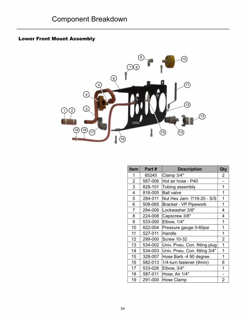
Lower Front Mount Assembly
1 2
4
5
3
6
7 8
9 10
11
12
13
1415
16
171819
Component Breakdown
Item Part # Description Qty1 85245 Clamp 3/4'' 22 587-006 Hot air hose - P40 -3 828-101 Tubing assembly 14 816-005 Ball valve 15 284-011 Nut Hex Jam- 7/16-20 - S/S 16 508-065 Bracket - VP Pipework 17 294-009 Lockwasher 3/8" 48 224-008 Capscrew 3/8" 49 533-000 Elbow, 1/4" 1
10 822-004 Pressure gauge 0-60psi 111 527-011 Handle 112 299-000 Screw 10-32 213 534-002 Univ. Pneu. Con. fitting plug 114 534-003 Univ. Pneu. Con. fitting 3/4" 115 328-007 Hose Barb -4 90 degree 116 582-013 1/4-turn fastener (9mm) 617 533-026 Elbow, 3/4" 118 587-011 Hose, Air 1/4" -19 291-000 Hose Clamp 2
25
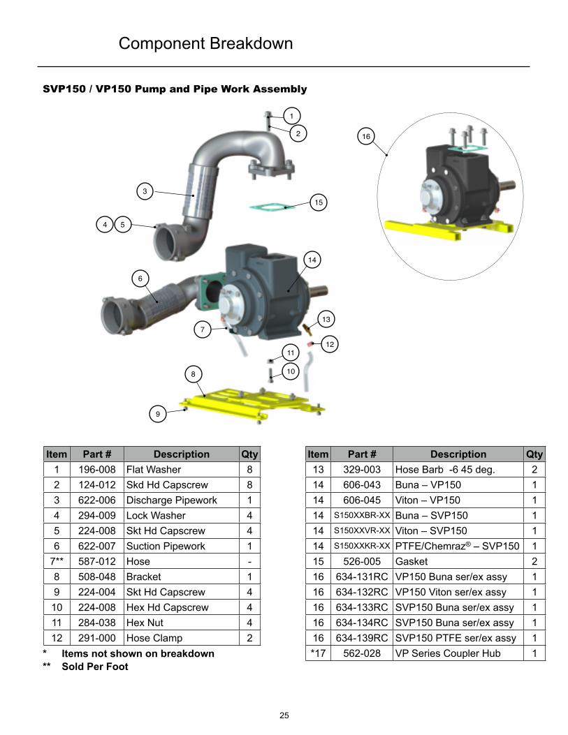
SVP150 / VP150 Pump and Pipe Work Assembly
Item Part # Description Qty13 329-003 Hose Barb -6 45 deg. 214 606-043 Buna – VP150 114 606-045 Viton – VP150 114 S150XXBR-XX Buna – SVP150 114 S150XXVR-XX Viton – SVP150 114 S150XXKR-XX PTFE/Chemraz® – SVP150 115 526-005 Gasket 216 634-131RC VP150 Buna ser/ex assy 116 634-132RC VP150 Viton ser/ex assy 116 634-133RC SVP150 Buna ser/ex assy 116 634-134RC SVP150 Buna ser/ex assy 116 634-139RC SVP150 PTFE ser/ex assy 1*17 562-028 VP Series Coupler Hub 1
Item Part # Description Qty1 196-008 Flat Washer 82 124-012 Skd Hd Capscrew 83 622-006 Discharge Pipework 14 294-009 Lock Washer 45 224-008 Skt Hd Capscrew 46 622-007 Suction Pipework 1
7** 587-012 Hose -8 508-048 Bracket 19 224-004 Skt Hd Capscrew 4
10 224-008 Hex Hd Capscrew 411 284-038 Hex Nut 412 291-000 Hose Clamp 2
* Items not shown on breakdown** Sold Per Foot
Component Breakdown
1
2
153
54
6
7
8
9
10
1112
13
14
16

26
G125 Pump and Pipe Work Assembly
Item Part # Description Qty9 224-004 Skt Hd Capscrew 4
10 224-008 Skt Hd Capscrew 411 294-009 Lock Washer 412 622-015 Inlet Pipework Assy 113 634-136RC G125,Steel, C - Bush. Assy 113 634-135RC G125,Steel, B - Bush. Assy 113 634-138RC G125,S/S, C - Bush. Assy 113 634-137RC G125,S/S, B - Bush. Assy 114* 327-016 Hose Barb -6 x NPT 115* 291-000 Hose Clamp 116** 587-012 Hose -17* 562-023 G125 Series Coupler Hub 1
Item Part # Description Qty1 228-070 Hex Hd Capscrew 82 622-014 Discharge Pipework Assy 13 526-027 Gasket 24 G125XXLLX-XX G125,Steel, Carbon Bush. 14 G125XXNLX-XX G125,Steel, Bronze Bush. 14 G125XXTLX-XX G125,S/S, Carbon Bush. 14 G125XXZLX-XX G125,S/S, Bronze Bush. 15 284-000 Hex Nut 46 296-010 Flat Washer 47 228-074 Hex Hd Capscrew 48 294-010 Lock Washer 4
* Items not shown on breakdown** Sold Per Foot
Component Breakdown
1
2
11
10
4
5
6
78
9
3
13
12

27
Notes

Warranty Subject to the terms and conditions hereinafter set forth in General Terms of Sale, Paragon Tank Truck Equipment LLC (the Seller) warrants products and parts of its manufacturer, when shipped and its work (including installation and start-up) when performed, will be of good quality and will be free from defects in material and workmanship. This warranty applies only to Seller’s equipment, under use and service of products, for a period as stated in the table below. Due to the varying condition of installation and operation, all performances claims are subject to a plus or minus 5% variation. (Non-standard materials are subject to a plus or minus 10% variation)
THIS WARRANTY EXTENDS ONLY TO BUYER AND/OR ORIGINAL END USER, AND IN NO EVENT SHALL THE SELLER BE LIABLE FOR THE PROPERTY DAMAGE SUSTAINED BY A PERSON DESIGNED BY THE LAW OF ANY JURISDICTION AS A THIRD PARTY BENEFICIARY OF THIS WARRANTY OR ANY OTHER WARRANTY HELD TO SURVIVE SELLER’S DISCLAIMER.
All accessories furnished by seller but manufactured by others bear only that manufacturer’s standard warranty.
All claims for defective products, parts, or work under this warranty must be made in writing immediately upon discovery and, in any event within one year from the date of the shipment of the applicable item and all claims for defective work must be made in writing immediately upon discovery and in any event within one year from date of completion thereof by Seller. Unless done with prior written consent of Seller, any repairs, alterations, or disassembly of Seller’s inspection and warranty. Installation and transportation costs are not included and defective items must be held for Seller’s inspection and warranty. Installation and transportation costs are not included and defective items must be held for Seller’s inspection and returned to Seller’s Ex-works upon request.
THERE ARE NO WARRANTIES, EXPRESSED, IMPLIED, OR STATUTORY WHICH EXTEND BEYOND THE DESCRIPTION ON THE FACE HEREOF, INCLUDING WITHOUT LIMITATION, THE IMPLIED WARRANTIES OF MERCHANTABILITY AND FITNESS OF PURPOSE.
After Buyer’s submission of claim as provided above and its approval, Seller shall either repair or replace its product, part, or work at the original Ex-works point of shipment, or refund an equitable portion of the purchase price.
The products and parts sold hereunder are not warranted for operation with erosive or corrosive materials or those which may lead to build up of materials within the product supplied, nor those which are incompatible with the materials of construction. The Buyer shall have no claim whatsoever and no product or part shall be deemed to be defective by reason of failure to resist erosive or corrosive action nor for problems resulting from build-up of material within the unit nor for problems due to incompatibility with the materials of construction.
Product Type Warranty Duration
New 18 months from date of shipment, or 12 months after initial startup date, whichever occurs first.
Remanufactured 12 months from date of shipment, or 12 months after initial startup date, whichever occurs first.
Repair 12 month from date of shipment, or remaining warranty period, whichever is greater.
Any improper use, operation beyond capacity, substitute of parts not approved by Seller, or any alteration or repair by others in such manner as in Seller’s judgement affects the product materially and adversely shall void this warranty.
No employee or representative of Seller other than an Officer of the Company is authorized to change this warranty in any way or grant other warranty. Any such change by an Officer of the Company must be in writing.
The foregoing is Seller’s only obligation and buyer’s only remedy for breach of warranty, and except for gross negligence, willful misconduct and remedies permitted under the General Terms of Sale in the sections on CONTRACT PERFORMANCE, INSPECTION AND ACCEPTANCE, and the PATENTS CLAUSE hereof, the forgoing is BUYER’S ONLY REMEDY HEREUNDER BY WAY OF BREACH OF CONTRACT TORT OR OTHERWISE, WITHOUT REGARD TO WORK WHETHER ANY DEFECT WAS DISCOVERED OR LATENT AT THE TIME OF DELIVERY OF THE PRODUCT OR WORK. In no event shall Buyer be entitled to incidental or consequential damages. Any action for breach of this agreement must commerce within one year after the cause of action has occurred.
Paragon Tank Truck Equipment LLC., 2111 US Hwy 411 NE | Cartersville, Georgia USA 30121Tel: 770-387-3820 | Toll: 800-471-8769 | Fax: 770-387-3824 | www.paragondirect.com | [email protected]
Copyright 2015 Paragon Tank Truck Equipment LLC
28