hydraulic chucks - ptsintl.com
TRANSCRIPT
Hydraulic Chucks
We reserve the right to change the design, data and dimensions without prior notice.
2
INDEX
Introduction 2 - 9
Index / Quick facts 2 - 3
System introduction / Example Hydraulic chucks 4 - 5
Facts about SPV SPINTEC milling membrane [+] 6 - 7
Options - Quick-set, Fine balancing, Torque table 8
Handeling, Maintenance, Tool shank info 9
Hydraulic chucks - CAT [inch] Form AD/B 10 - 18
Hydraulic chucks - CAT [mm] Form AD/B 16 - 24
Hydraulic chucks - HSK-A 25 - 31
Hydraulic chucks - BT-MAS 32 -37
Reduction sleeves / Torque mandrel 38
3
INTRODUCTION
QUICK FACTS ABOUT SPV SPINTEC HYDRAULIC CHUCKS
Why you should use our Hydraulic chucks
❙ High clamping force.
❙ Runout accuracy better than 0,003 mm.
❙ Quick application method for tools.
❙ Balanced for 10.000 rpm as standard - can be supplied fine balanced up to 30.000 rpm.
❙ Available with quick length adjustment from side (Quick-set).
❙ Widest range of hydraulic chucks on the market. Available for all applications.
Why you should use our Hydraulic chucks with milling membrane [+]
❙ They offer all the advantages of our standard Hydraulic chucks.
❙ Very stable tool fixing.
❙ Permits up to twice the recommended axial and radial cutting depths.
❙ Reduces vibration.
SPV SPINTEC’s Hydraulic chucks offer you:
❙ Increased tool life.
❙ Increased surface finish.
❙ Permits machining with much closer tolerances.
❙ Quicker and simpler tool changes.
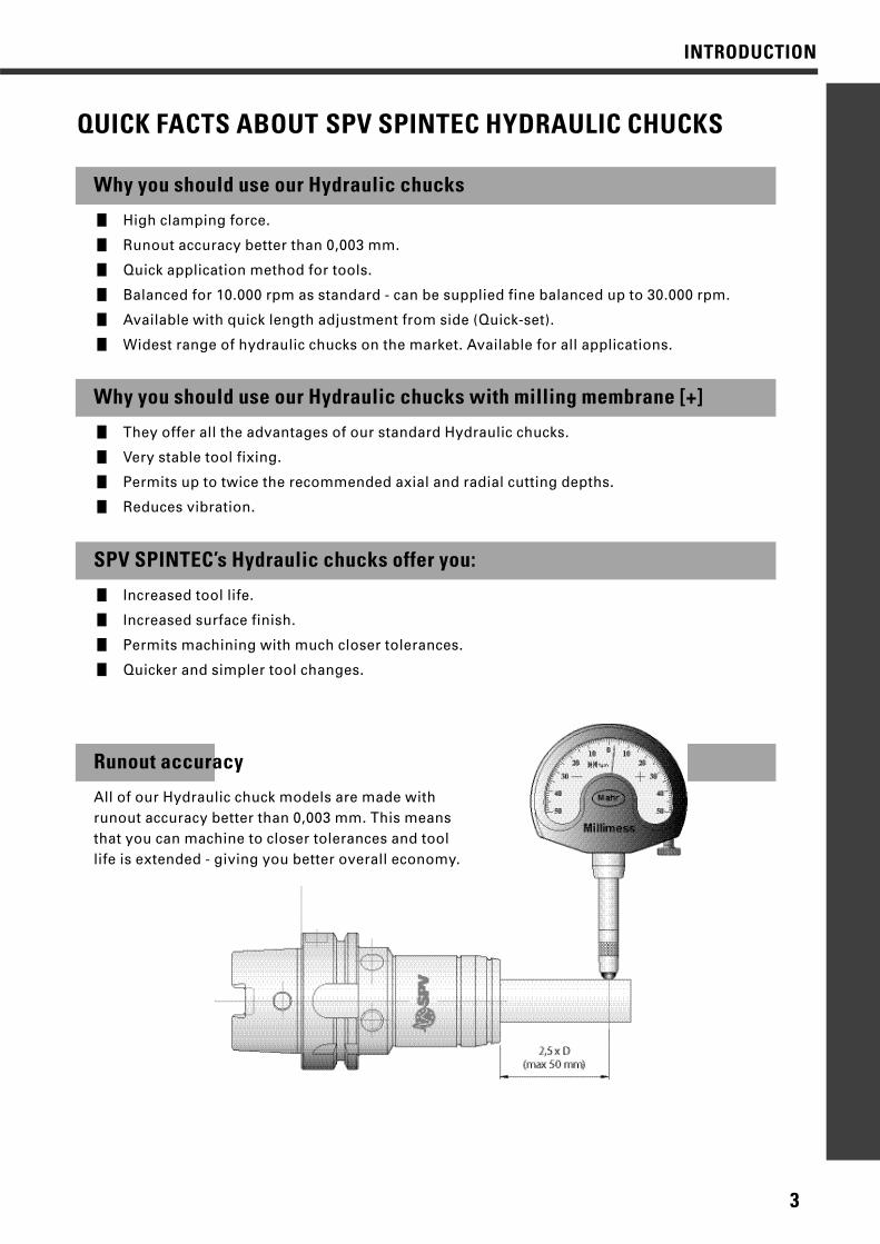
Runout accuracy
All of our Hydraulic chuck models are made with runout accuracy better than 0,003 mm. This means that you can machine to closer tolerances and tool life is extended - giving you better overall economy.
4
INTRODUCTION
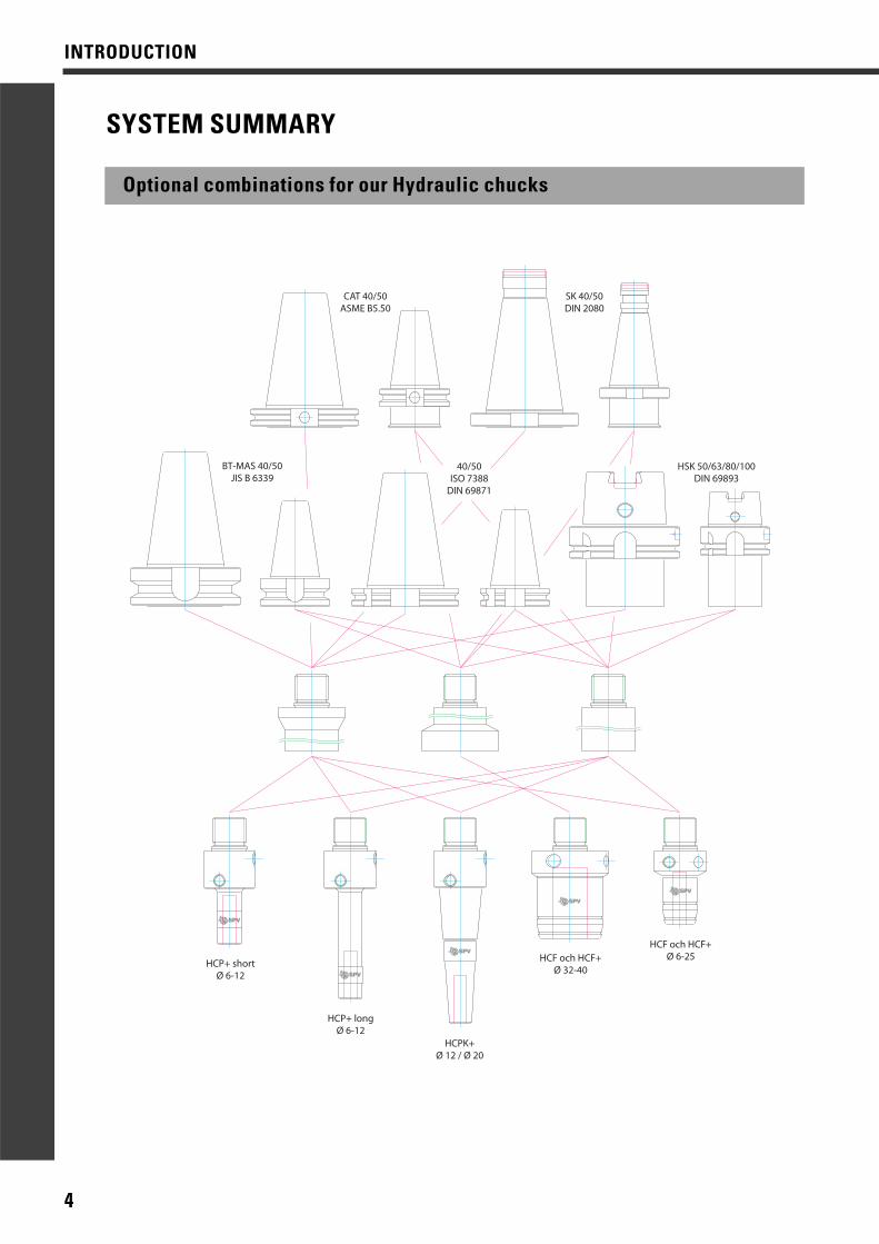
SYSTEM SUMMARY
Optional combinations for our Hydraulic chucks
CAT 40/50ASME B5.50
SK 40/50DIN 2080
BT-MAS 40/50JIS B 6339
HSK 50/63/80/100DIN 69893
HCP+ shortØ 6-12
HCP+ longØ 6-12
HCPK+Ø 12 / Ø 20
HCF och HCF+Ø 32-40
HCF och HCF+Ø 6-25
40/50ISO 7388
DIN 69871
5
INTRODUCTION
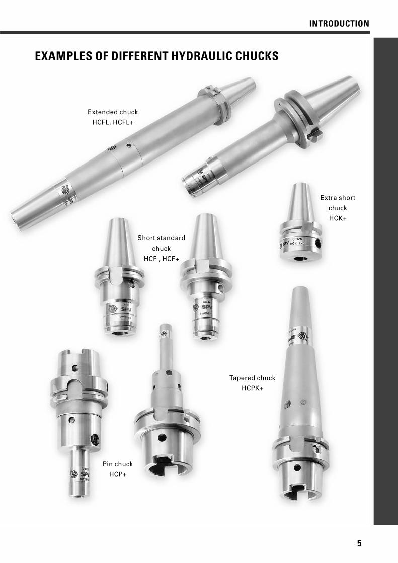
Short standard
chuck
HCF , HCF+
Extra short
chuck
HCK+
Extended chuck
HCFL, HCFL+
Pin chuck
HCP+
Tapered chuck
HCPK+
EXAMPLES OF DIFFERENT HYDRAULIC CHUCKS
6
INTRODUCTION
MILLING MEMBRANE [+]
Fact about Hydraulic chucks with milling membrane [+]
SPV SPINTEC’s hexagonal milling membrane (+membrane)permits tough, vibration-free milling. A highly stable toolanchorage makes it possible to machine at greater feedrates and with greater axial and radial depths of cut thannormally recommended.
Limitations of conventional Hydraulic chucksThe limitation in the use of hydraulic chucks has frequentlybeen the use of recommended cutting data for heavy dutymilling. Customers have often been obliged to purchasespecially shortened hydraulic milling chucks withincreased torque when they have needed to remove alarge amount of material in the shortest possible time.
We have eliminated this limitation and offers our cus-tomers the opportunity of using the newly-developedhydraulic milling chuck for both drilling and milling, which offers better overall economy.
Development - historyDevelopment started when British Aerospace in Englandhad problems with milling vibration, which lead to veryshort life for their expensive, solid metal cutters.
BA tried several commercially available retention systemsbut did not find a satisfactory solution. We then developedthe hexagonal milling membrane which was found in testsat British Aerospace to multiply the period of contact several times over and in some cases, enabled them todouble both radial and axial cutting depths.
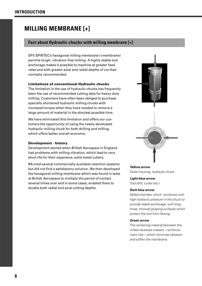
Yellow arrow
Outer housing, hydraulic chuck.
Light blue arrow
Tool (drill, cutter etc.)
Dark blue arrow
Milled chamber which combines withhigh hydraulic pressure in the chuck toprovide stable anchorage, with long, linear, thinwall gripping surfaces whichprotect the tool from flexing.
Green arrow
The remaining material between themilled recesses creates – reinforce-ment ribs – which minimise vibrationand stiffen the membrane.
7
INTRODUCTION
Coarse slab milling with rotational speed and
feed rate to Jabro’s recommendations:
Recommended depth of cut:axial = 1x tool diameterradial = 0.4x tool diameterThis gives a chip area of:1x D mm x 0.4x D mm = 0.4x D mm2
Coarse slab-milling with rotational speed and
feed rate to Jabro’s recommendations:
HCF+ test with twice the recommended depth ofcut, axially and radiallyThis gives a chip area of:2x D mm x 0.8x D mm = 1.6x D mm2
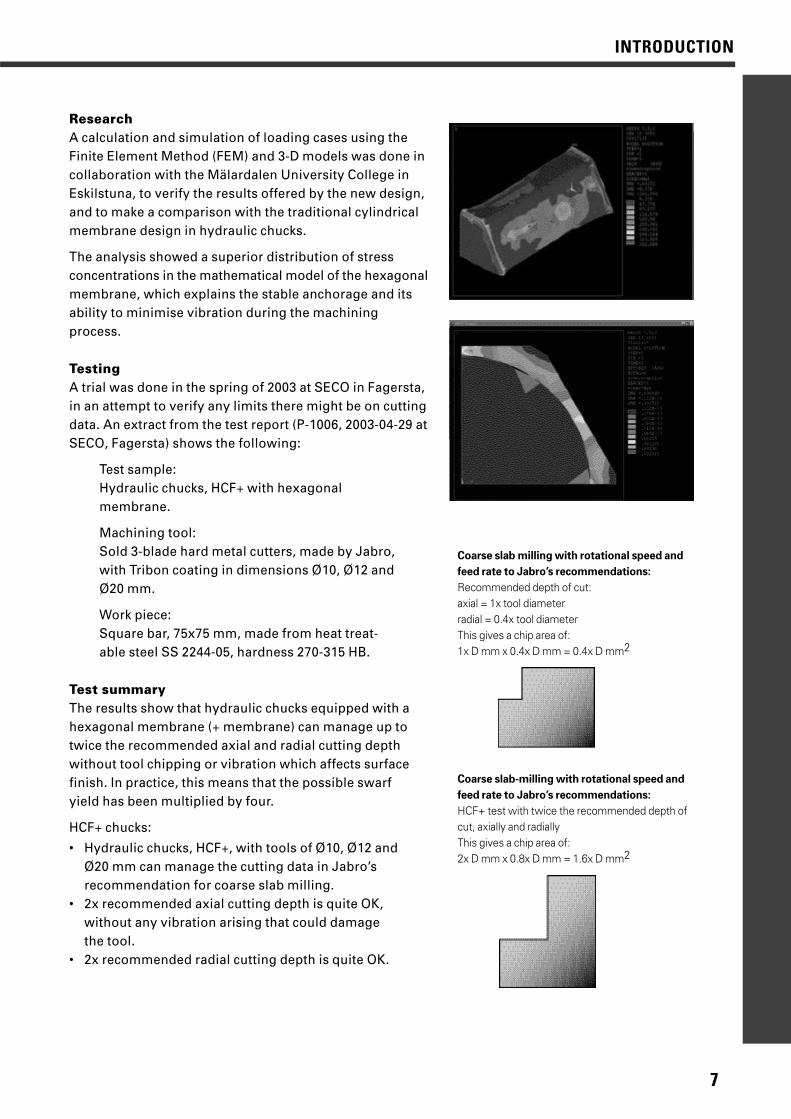
ResearchA calculation and simulation of loading cases using theFinite Element Method (FEM) and 3-D models was done incollaboration with the Mälardalen University College inEskilstuna, to verify the results offered by the new design,and to make a comparison with the traditional cylindricalmembrane design in hydraulic chucks.
The analysis showed a superior distribution of stress concentrations in the mathematical model of the hexagonalmembrane, which explains the stable anchorage and itsability to minimise vibration during the machiningprocess.
TestingA trial was done in the spring of 2003 at SECO in Fagersta,in an attempt to verify any limits there might be on cuttingdata. An extract from the test report (P-1006, 2003-04-29 atSECO, Fagersta) shows the following:
Test sample:Hydraulic chucks, HCF+ with hexagonal membrane.
Machining tool:Sold 3-blade hard metal cutters, made by Jabro,with Tribon coating in dimensions Ø10, Ø12 andØ20 mm.
Work piece:Square bar, 75x75 mm, made from heat treat-able steel SS 2244-05, hardness 270-315 HB.
Test summaryThe results show that hydraulic chucks equipped with ahexagonal membrane (+ membrane) can manage up totwice the recommended axial and radial cutting depthwithout tool chipping or vibration which affects surfacefinish. In practice, this means that the possible swarf yield has been multiplied by four.
HCF+ chucks:
• Hydraulic chucks, HCF+, with tools of Ø10, Ø12 and Ø20 mm can manage the cutting data in Jabro’s recommendation for coarse slab milling.
• 2x recommended axial cutting depth is quite OK, without any vibration arising that could damage the tool.
• 2x recommended radial cutting depth is quite OK.
8
INTRODUCTION
OPTION
Quick-set and Fine balancing
In most of our hydraulic chucks, it is possible to combine the standard version of the chuck with one or more optional features. In this way, you can design your hydraulic chucks to suityour needs.
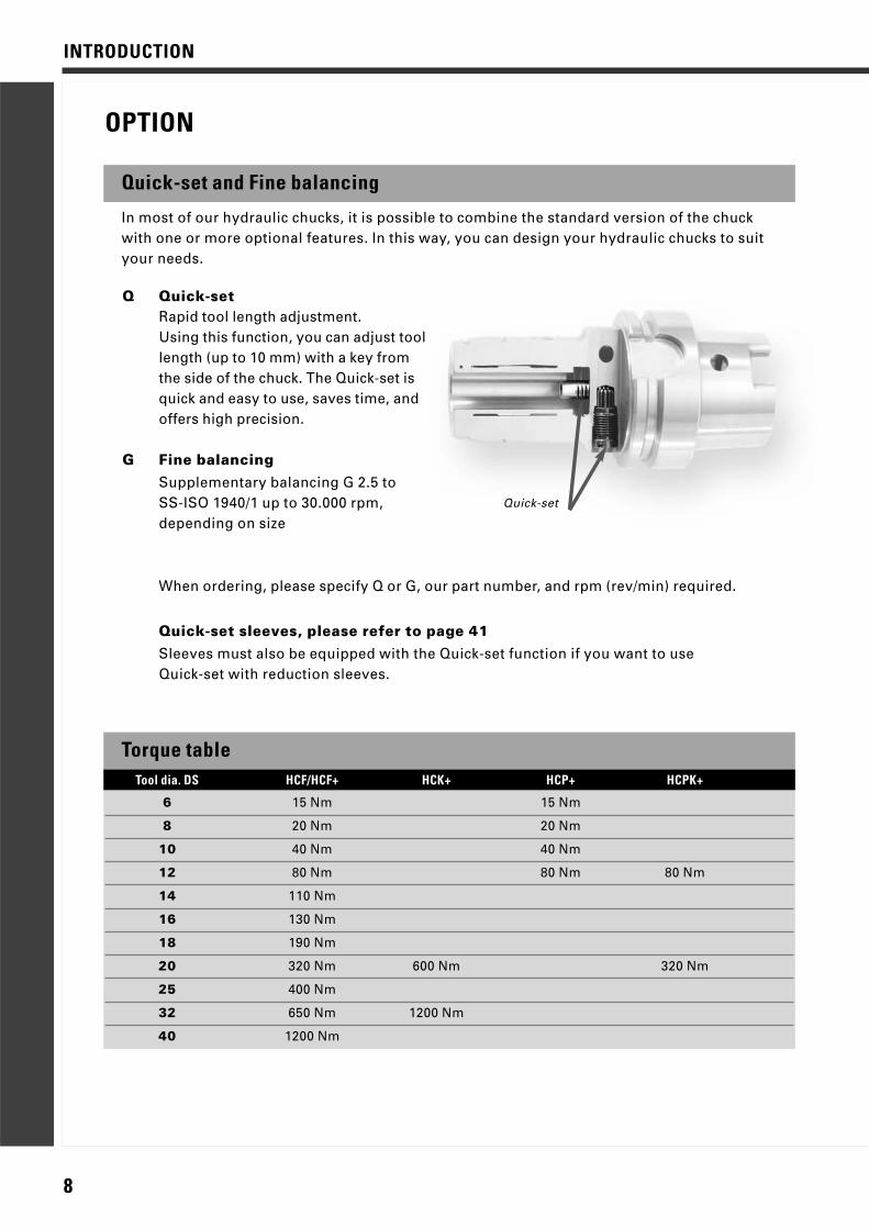
Q Quick-setRapid tool length adjustment.Using this function, you can adjust tool length (up to 10 mm) with a key from the side of the chuck. The Quick-set is quick and easy to use, saves time, and offers high precision.
G Fine balancingSupplementary balancing G 2.5 to SS-ISO 1940/1 up to 30.000 rpm, depending on size
When ordering, please specify Q or G, our part number, and rpm (rev/min) required.
Quick-set sleeves, please refer to page 41Sleeves must also be equipped with the Quick-set function if you want to useQuick-set with reduction sleeves.
Quick-set
Torque table
6 15 Nm 15 Nm
8 20 Nm 20 Nm
10 40 Nm 40 Nm
12 80 Nm 80 Nm 80 Nm
14 110 Nm
16 130 Nm
18 190 Nm
20 320 Nm 600 Nm 320 Nm
25 400 Nm
32 650 Nm 1200 Nm
40 1200 Nm
Tool dia. DS HCF/HCF+ HCK+ HCP+ HCPK+
9
INTRODUCTION
HANDELING, MAINTENANCE
Operation of Hydraulic chucks
Tool shank info
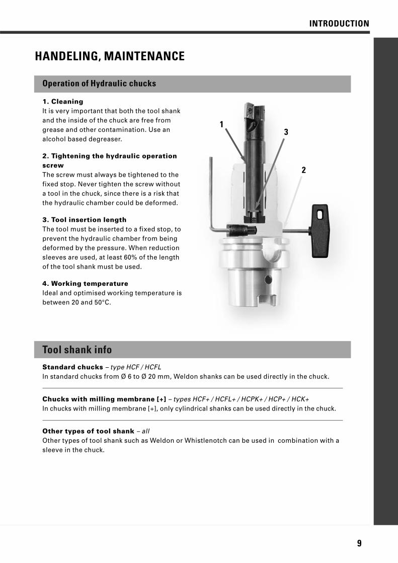
1. CleaningIt is very important that both the tool shankand the inside of the chuck are free fromgrease and other contamination. Use analcohol based degreaser.
2. Tightening the hydraulic operationscrewThe screw must always be tightened to thefixed stop. Never tighten the screw withouta tool in the chuck, since there is a risk thatthe hydraulic chamber could be deformed.
3. Tool insertion lengthThe tool must be inserted to a fixed stop, toprevent the hydraulic chamber from beingdeformed by the pressure. When reductionsleeves are used, at least 60% of the lengthof the tool shank must be used.
4. Working temperatureIdeal and optimised working temperature isbetween 20 and 50°C.
Standard chucks – type HCF / HCFLIn standard chucks from Ø 6 to Ø 20 mm, Weldon shanks can be used directly in the chuck.
Chucks with milling membrane [+] – types HCF+ / HCFL+ / HCPK+ / HCP+ / HCK+In chucks with milling membrane [+], only cylindrical shanks can be used directly in the chuck.
Other types of tool shank – allOther types of tool shank such as Weldon or Whistlenotch can be used in combination with asleeve in the chuck.
2
13
10
HYDRAULIC CHUCKS - ISO 7388 / DIN 69871 Form AD/BIS
O 7
388
/DIN
698
71 F
orm
AD
/B
type of tool shank, please refer to page 9
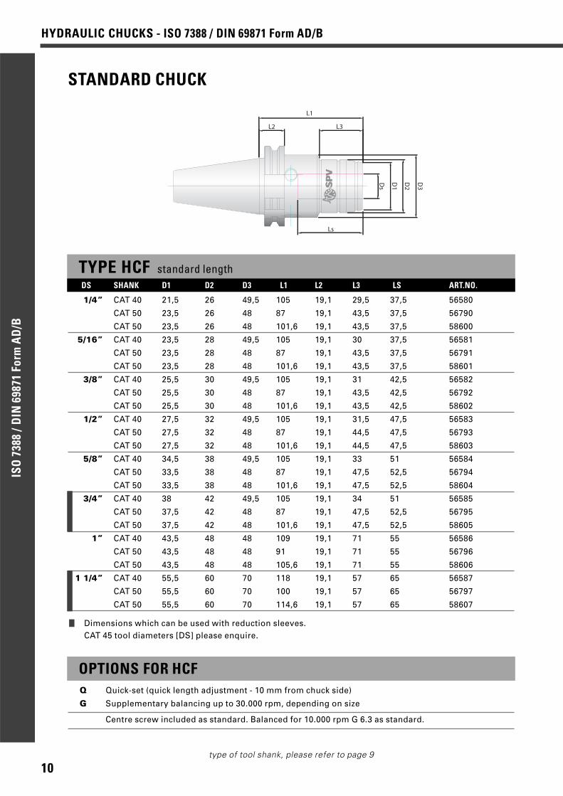
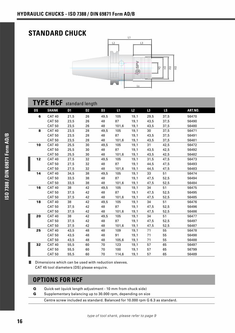
STANDARD CHUCK
TYPE HCF standard lengthDS SHANK D1 D2 D3 L1 L2 L3 LS ART.NO.
1/4” CAT 40 21,5 26 49,5 105 19,1 29,5 37,5 56580
CAT 50 23,5 26 48 87 19,1 43,5 37,5 56790
CAT 50 23,5 26 48 101,6 19,1 43,5 37,5 58600
5/16” CAT 40 23,5 28 49,5 105 19,1 30 37,5 56581
CAT 50 23,5 28 48 87 19,1 43,5 37,5 56791
CAT 50 23,5 28 48 101,6 19,1 43,5 37,5 58601
3/8” CAT 40 25,5 30 49,5 105 19,1 31 42,5 56582
CAT 50 25,5 30 48 87 19,1 43,5 42,5 56792
CAT 50 25,5 30 48 101,6 19,1 43,5 42,5 58602
1/2” CAT 40 27,5 32 49,5 105 19,1 31,5 47,5 56583
CAT 50 27,5 32 48 87 19,1 44,5 47,5 56793
CAT 50 27,5 32 48 101,6 19,1 44,5 47,5 58603
5/8” CAT 40 34,5 38 49,5 105 19,1 33 51 56584
CAT 50 33,5 38 48 87 19,1 47,5 52,5 56794
CAT 50 33,5 38 48 101,6 19,1 47,5 52,5 58604
3/4” CAT 40 38 42 49,5 105 19,1 34 51 56585
CAT 50 37,5 42 48 87 19,1 47,5 52,5 56795
CAT 50 37,5 42 48 101,6 19,1 47,5 52,5 58605
1” CAT 40 43,5 48 48 109 19,1 71 55 56586
CAT 50 43,5 48 48 91 19,1 71 55 56796
CAT 50 43,5 48 48 105,6 19,1 71 55 58606
1 1/4” CAT 40 55,5 60 70 118 19,1 57 65 56587
CAT 50 55,5 60 70 100 19,1 57 65 56797
CAT 50 55,5 60 70 114,6 19,1 57 65 58607
OPTIONS FOR HCFQ Quick-set (quick length adjustment - 10 mm from chuck side)
G Supplementary balancing up to 30.000 rpm, depending on size
Centre screw included as standard. Balanced for 10.000 rpm G 6.3 as standard.
D1
Ds
L1
Ls
D2
D3
L2 L3
❙ Dimensions which can be used with reduction sleeves.CAT 45 tool diameters [DS] please enquire.
11
HYDRAULIC CHUCKS - ISO 7388 / DIN 69871 Form AD/B
ISO
738
8 /D
IN 6
9871
For
m A
D/B
type of tool shank, please refer to page 9
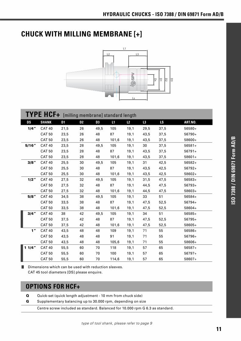
CHUCK WITH MILLING MEMBRANE [+]
TYPE HCF+ [milling membrane] standard lengthDS SHANK D1 D2 D3 L1 L2 L3 LS ART.NO.
1/4” CAT 40 21,5 26 49,5 105 19,1 29,5 37,5 56580+
CAT 50 23,5 26 48 87 19,1 43,5 37,5 56790+
CAT 50 23,5 26 48 101,6 19,1 43,5 37,5 58600+
5/16” CAT 40 23,5 28 49,5 105 19,1 30 37,5 56581+
CAT 50 23,5 28 48 87 19,1 43,5 37,5 56791+
CAT 50 23,5 28 48 101,6 19,1 43,5 37,5 58601+
3/8” CAT 40 25,5 30 49,5 105 19,1 31 42,5 56582+
CAT 50 25,5 30 48 87 19,1 43,5 42,5 56792+
CAT 50 25,5 30 48 101,6 19,1 43,5 42,5 58602+
1/2” CAT 40 27,5 32 49,5 105 19,1 31,5 47,5 56583+
CAT 50 27,5 32 48 87 19,1 44,5 47,5 56793+
CAT 50 27,5 32 48 101,6 19,1 44,5 47,5 58603+
5/8” CAT 40 34,5 38 49,5 105 19,1 33 51 56584+
CAT 50 33,5 38 48 87 19,1 47,5 52,5 56794+
CAT 50 33,5 38 48 101,6 19,1 47,5 52,5 58604+
3/4” CAT 40 38 42 49,5 105 19,1 34 51 56585+
CAT 50 37,5 42 48 87 19,1 47,5 52,5 56795+
CAT 50 37,5 42 48 101,6 19,1 47,5 52,5 58605+
1” CAT 40 43,5 48 48 109 19,1 71 55 56586+
CAT 50 43,5 48 48 91 19,1 71 55 56796+
CAT 50 43,5 48 48 105,6 19,1 71 55 58606+
1 1/4” CAT 40 55,5 60 70 118 19,1 57 65 56587+
CAT 50 55,5 60 70 100 19,1 57 65 56797+
CAT 50 55,5 60 70 114,6 19,1 57 65 58607+
D1
Ds
L1
Ls
D2
D3
L2 L3
OPTIONS FOR HCF+Q Quick-set (quick length adjustment - 10 mm from chuck side)
G Supplementary balancing up to 30.000 rpm, depending on size
Centre screw included as standard. Balanced for 10.000 rpm G 6.3 as standard.
❙ Dimensions which can be used with reduction sleeves.CAT 45 tool diameters [DS] please enquire.

12
HYDRAULIC CHUCKS - ISO 7388 / DIN 69871 Form AD/BIS
O 7
388
/DIN
698
71 F
orm
AD
/B
type of tool shank, please refer to page 9
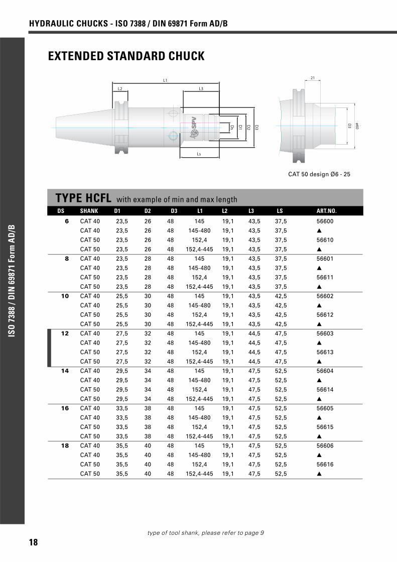
EXTENDED STANDARD CHUCK
TYPE HCFL with example of min and max lengthDS SHANK D1 D2 D3 L1 L2 L3 LS ART.NO.
1/4” CAT 40 23,5 26 48 145 19,1 43,5 37,5 56780
CAT 40 23,5 26 48 145-480 19,1 43,5 37,5 ▲
CAT 50 23,5 26 48 152,4 19,1 43,5 37,5 56740
CAT 50 23,5 26 48 152,4-445 19,1 43,5 37,5 ▲
5/16” CAT 40 23,5 28 48 145 19,1 43,5 37,5 56781
CAT 40 23,5 28 48 145-480 19,1 43,5 37,5 ▲
CAT 50 23,5 28 48 152,4 19,1 43,5 37,5 56741
CAT 50 23,5 28 48 152,4-445 19,1 43,5 37,5 ▲
3/8” CAT 40 25,5 30 48 145 19,1 43,5 42,5 56782
CAT 40 25,5 30 48 145-480 19,1 43,5 42,5 ▲
CAT 50 25,5 30 48 152,4 19,1 43,5 42,5 56742
CAT 50 25,5 30 48 152,4-445 19,1 43,5 42,5 ▲
1/2” CAT 40 27,5 32 48 145 19,1 44,5 47,5 56783
CAT 40 27,5 32 48 145-480 19,1 44,5 47,5 ▲
CAT 50 27,5 32 48 152,4 19,1 44,5 47,5 56743
CAT 50 27,5 32 48 152,4-445 19,1 44,5 47,5 ▲
5/8” CAT 40 33,5 38 48 145 19,1 47,5 52,5 56785
CAT 40 33,5 38 48 145-480 19,1 47,5 52,5 ▲
CAT 50 33,5 38 48 152,4 19,1 47,5 52,5 56745
CAT 50 33,5 38 48 152,4-445 19,1 47,5 52,5 ▲
D1
Ds
L1
LsD
2
D3
L2 L3
D3
ø60
21
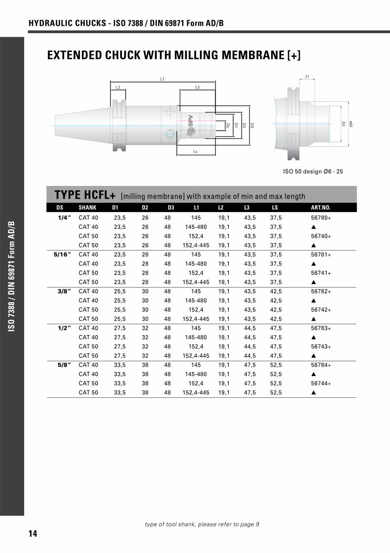
ISO 50 design Ø6 - 25

13
HYDRAULIC CHUCKS - ISO 7388 / DIN 69871 Form AD/B
ISO
738
8 /D
IN 6
9871
For
m A
D/B
type of tool shank, please refer to page 9
TYPE HCFL with example of min and max length
3/4” CAT 40 37,5 42 48 145 19,1 47,5 52,5 56785
CAT 40 37,5 42 48 145-480 19,1 47,5 52,5 ▲
CAT 50 37,5 42 48 152,4 19,1 47,5 52,5 56745
CAT 50 37,5 42 48 152,4-445 19,1 47,5 52,5 ▲
1” CAT 40 43,5 48 48 149 19,1 114 55 56786
CAT 40 43,5 48 48 149-480 19,1 - 55 ▲
CAT 50 43,5 48 48 156,4 19,1 144 55 56746
CAT 50 43,5 48 48 156,4-445 19,1 - 55 ▲
1 1/4” CAT 40 55,5 60 70 158 19,1 141 65 56787
CAT 40 55,5 60 70 158-480 19,1 - 65 ▲
CAT 50 55,5 60 70 160 19,1 141 65 56747
CAT 50 55,5 60 70 160-445 19,1 - 65 ▲
OPTIONS FOR HCFLQ Quick-set (quick length adjustment - 10 mm from chuck side)
G Supplementary balancing up to 30.000 rpm, depending on size
Centre screw included as standard. Balanced for 10.000 rpm G 6.3 as standard.
EXTRA LONG CHUCKS HCFL any length L1 as table
Ordering example
▲ CAT 40, Ø1/2”, L1=290 mm, type HCFL Art.no.: 56783/290
L1
❙ Dimensions which can be used with reduction sleeves.▲ Depending on L1 chosen
CAT 45 tool diameters [DS] please enquire.
DS SHANK D1 D2 D3 L1 L2 L3 LS ART.NO.
14
HYDRAULIC CHUCKS - ISO 7388 / DIN 69871 Form AD/BIS
O 7
388
/DIN
698
71 F
orm
AD
/B
type of tool shank, please refer to page 9
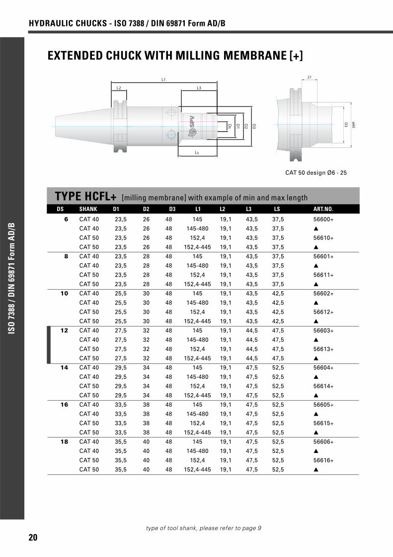
EXTENDED CHUCK WITH MILLING MEMBRANE [+]
D1
Ds
L1
LsD
2
D3
L2 L3
D3
ø60
21
ISO 50 design Ø6 - 25
TYPE HCFL+ [milling membrane] with example of min and max lengthDS SHANK D1 D2 D3 L1 L2 L3 LS ART.NO.
1/4” CAT 40 23,5 26 48 145 19,1 43,5 37,5 56780+
CAT 40 23,5 26 48 145-480 19,1 43,5 37,5 ▲
CAT 50 23,5 26 48 152,4 19,1 43,5 37,5 56740+
CAT 50 23,5 26 48 152,4-445 19,1 43,5 37,5 ▲
5/16” CAT 40 23,5 28 48 145 19,1 43,5 37,5 56781+
CAT 40 23,5 28 48 145-480 19,1 43,5 37,5 ▲
CAT 50 23,5 28 48 152,4 19,1 43,5 37,5 56741+
CAT 50 23,5 28 48 152,4-445 19,1 43,5 37,5 ▲
3/8” CAT 40 25,5 30 48 145 19,1 43,5 42,5 56782+
CAT 40 25,5 30 48 145-480 19,1 43,5 42,5 ▲
CAT 50 25,5 30 48 152,4 19,1 43,5 42,5 56742+
CAT 50 25,5 30 48 152,4-445 19,1 43,5 42,5 ▲
1/2” CAT 40 27,5 32 48 145 19,1 44,5 47,5 56783+
CAT 40 27,5 32 48 145-480 19,1 44,5 47,5 ▲
CAT 50 27,5 32 48 152,4 19,1 44,5 47,5 56743+
CAT 50 27,5 32 48 152,4-445 19,1 44,5 47,5 ▲
5/8” CAT 40 33,5 38 48 145 19,1 47,5 52,5 56784+
CAT 40 33,5 38 48 145-480 19,1 47,5 52,5 ▲
CAT 50 33,5 38 48 152,4 19,1 47,5 52,5 56744+
CAT 50 33,5 38 48 152,4-445 19,1 47,5 52,5 ▲

15
HYDRAULIC CHUCKS - ISO 7388 / DIN 69871 Form AD/B
ISO
738
8 /D
IN 6
9871
For
m A
D/B
type of tool shank, please refer to page 9
L1
TYPE HCFL+ [milling membrane] with example of min and max length
3/4” CAT 40 37,5 42 48 145 19,1 47,5 52,5 56785+
CAT 40 37,5 42 48 145-480 19,1 47,5 52,5 ▲
CAT 50 37,5 42 48 152,4 19,1 47,5 52,5 56745+
CAT 50 37,5 42 48 152,4-445 19,1 47,5 52,5 ▲
1” CAT 40 43,5 48 48 149 19,1 114 55 56786+
CAT 40 43,5 48 48 149-480 19,1 - 55 ▲
CAT 50 43,5 48 48 156,4 19,1 144 55 56746+
CAT 50 43,5 48 48 156,4-445 19,1 - 55 ▲
1 1/4” CAT 40 55,5 60 70 158 19,1 141 65 56787+
CAT 40 55,5 60 70 158-480 19,1 - 65 ▲
CAT 50 55,5 60 70 160 19,1 141 65 56747+
CAT 50 55,5 60 70 160-445 19,1 - 65 ▲
OPTIONS FOR HCFL+Q Quick-set (quick length adjustment - 10 mm from chuck side)
G Supplementary balancing up to 30.000 rpm, depending on size
Centre screw included as standard. Balanced for 10.000 rpm G 6.3 as standard.
EXTRA LONG CHUCKS HCFL+ [milling membrane] any length L1 as table
Ordering example
▲ CAT 40, Ø1/2”, L1=290 mm, type HCFL+ Art.no.: 56783+/290
❙ Dimensions which can be used with reduction sleeves.▲ Depending on L1 chosen
CAT 45 tool diameters [DS] please enquire.
DS SHANK D1 D2 D3 L1 L2 L3 LS ART.NO.
HYDRAULIC CHUCKS - ISO 7388 / DIN 69871 Form AD/BIS
O 7
388
/DIN
698
71 F
orm
AD
/B
type of tool shank, please refer to page 9
STANDARD CHUCK
TYPE HCF standard lengthDS SHANK D1 D2 D3 L1 L2 L3 LS ART.NO.
6 CAT 40 21,5 26 49,5 105 19,1 29,5 37,5 56470CAT 50 23,5 26 48 87 19,1 43,5 37,5 56490CAT 50 23,5 26 48 101,6 19,1 43,5 37,5 56480
8 CAT 40 23,5 28 49,5 105 19,1 30 37,5 56471CAT 50 23,5 28 48 87 19,1 43,5 37,5 56491CAT 50 23,5 28 48 101,6 19,1 43,5 37,5 56481
10 CAT 40 25,5 30 49,5 105 19,1 31 42,5 56472CAT 50 25,5 30 48 87 19,1 43,5 42,5 56492CAT 50 25,5 30 48 101,6 19,1 43,5 42,5 56482
12 CAT 40 27,5 32 49,5 105 19,1 31,5 47,5 56473CAT 50 27,5 32 48 87 19,1 44,5 47,5 56493CAT 50 27,5 32 48 101,6 19,1 44,5 47,5 56483
14 CAT 40 34,5 38 49,5 105 19,1 33 51 56474CAT 50 33,5 38 48 87 19,1 47,5 52,5 56494CAT 50 33,5 38 48 101,6 19,1 47,5 52,5 56484
16 CAT 40 38 42 49,5 105 19,1 34 51 56475CAT 50 37,5 42 48 87 19,1 47,5 52,5 56495CAT 50 37,5 42 48 101,6 19,1 47,5 52,5 56485
18 CAT 40 38 42 49,5 105 19,1 34 51 56476CAT 50 37,5 42 48 87 19,1 47,5 52,5 56496CAT 50 37,5 42 48 101,6 19,1 47,5 52,5 56486
20 CAT 40 38 42 49,5 105 19,1 34 51 56477CAT 50 37,5 42 48 87 19,1 47,5 52,5 56497CAT 50 37,5 42 48 101,6 19,1 47,5 52,5 56487
25 CAT 40 43,5 48 48 109 19,1 71 55 56478CAT 50 43,5 48 48 91 19,1 71 55 56498CAT 50 43,5 48 48 105,6 19,1 71 55 56488
32 CAT 40 55,5 60 70 123 19,1 57 65 56497CAT 50 55,5 60 70 100 19,1 57 65 56799CAT 50 55,5 60 70 114,6 19,1 57 65 56489
D1
Ds
L1
Ls
D2
D3
L2 L3
❙ Dimensions which can be used with reduction sleeves.CAT 45 tool diameters [DS] please enquire.
OPTIONS FOR HCFQ Quick-set (quick length adjustment - 10 mm from chuck side)G Supplementary balancing up to 30.000 rpm, depending on size
Centre screw included as standard. Balanced for 10.000 rpm G 6.3 as standard.
16

17
HYDRAULIC CHUCKS - ISO 7388 / DIN 69871 Form AD/B
ISO
738
8 /D
IN 6
9871
For
m A
D/B
type of tool shank, please refer to page 9
CHUCK WITH MILLING MEMBRANE [+]
D1
Ds
L1
Ls
D2
D3
L2 L3
TYPE HCF+ [milling membrane] standard lengthDS SHANK D1 D2 D3 L1 L2 L3 LS ART.NO.
6 CAT 40 21,5 26 49,5 105 19,1 29,5 37,5 56470+CAT 50 23,5 26 48 87 19,1 43,5 37,5 56490+CAT 50 23,5 26 48 101,6 19,1 43,5 37,5 56480+
8 CAT 40 23,5 28 49,5 105 19,1 30 37,5 56471+CAT 50 23,5 28 48 87 19,1 43,5 37,5 56491+CAT 50 23,5 28 48 101,6 19,1 43,5 37,5 56481+
10 CAT 40 25,5 30 49,5 105 19,1 31 42,5 56472+CAT 50 25,5 30 48 87 19,1 43,5 42,5 56492+CAT 50 25,5 30 48 101,6 19,1 43,5 42,5 56482+
12 CAT 40 27,5 32 49,5 105 19,1 31,5 47,5 56473+CAT 50 27,5 32 48 87 19,1 44,5 47,5 56493+CAT 50 27,5 32 48 101,6 19,1 44,5 47,5 56483+
14 CAT 40 34,5 38 49,5 105 19,1 33 51 56474+CAT 50 33,5 38 48 87 19,1 47,5 52,5 56494+CAT 50 33,5 38 48 101,6 19,1 47,5 52,5 56484+
16 CAT 40 38 42 49,5 105 19,1 34 51 56475+CAT 50 37,5 42 48 87 19,1 47,5 52,5 56495+CAT 50 37,5 42 48 101,6 19,1 47,5 52,5 56485+
18 CAT 40 38 42 49,5 105 19,1 34 51 56476+CAT 50 37,5 42 48 87 19,1 47,5 52,5 56496+CAT 50 37,5 42 48 101,6 19,1 47,5 52,5 56486+
20 CAT 40 38 42 49,5 105 19,1 34 51 56477+CAT 50 37,5 42 48 87 19,1 47,5 52,5 56497+CAT 50 37,5 42 48 101,6 19,1 47,5 52,5 56487+
25 CAT 40 43,5 48 48 109 19,1 71 55 56478+CAT 50 43,5 48 48 91 19,1 71 55 56498+CAT 50 43,5 48 48 105,6 19,1 71 55 56488+
32 CAT 40 55,5 60 70 123 19,1 57 65 56497+CAT 50 55,5 60 70 100 19,1 57 65 56799+CAT 50 55,5 60 70 114,6 19,1 57 65 56489+
❙ Dimensions which can be used with reduction sleeves.CAT 45 tool diameters [DS] please enquire.
OPTIONS FOR HCF+Q Quick-set (quick length adjustment - 10 mm from chuck side)G Supplementary balancing up to 30.000 rpm, depending on size
Centre screw included as standard. Balanced for 10.000 rpm G 6.3 as standard.
18
HYDRAULIC CHUCKS - ISO 7388 / DIN 69871 Form AD/BIS
O 7
388
/DIN
698
71 F
orm
AD
/B
type of tool shank, please refer to page 9
EXTENDED STANDARD CHUCK
TYPE HCFL with example of min and max lengthDS SHANK D1 D2 D3 L1 L2 L3 LS ART.NO.
6 CAT 40 23,5 26 48 145 19,1 43,5 37,5 56600
CAT 40 23,5 26 48 145-480 19,1 43,5 37,5 ▲
CAT 50 23,5 26 48 152,4 19,1 43,5 37,5 56610
CAT 50 23,5 26 48 152,4-445 19,1 43,5 37,5 ▲
8 CAT 40 23,5 28 48 145 19,1 43,5 37,5 56601
CAT 40 23,5 28 48 145-480 19,1 43,5 37,5 ▲
CAT 50 23,5 28 48 152,4 19,1 43,5 37,5 56611
CAT 50 23,5 28 48 152,4-445 19,1 43,5 37,5 ▲
10 CAT 40 25,5 30 48 145 19,1 43,5 42,5 56602
CAT 40 25,5 30 48 145-480 19,1 43,5 42,5 ▲
CAT 50 25,5 30 48 152,4 19,1 43,5 42,5 56612
CAT 50 25,5 30 48 152,4-445 19,1 43,5 42,5 ▲
12 CAT 40 27,5 32 48 145 19,1 44,5 47,5 56603
CAT 40 27,5 32 48 145-480 19,1 44,5 47,5 ▲
CAT 50 27,5 32 48 152,4 19,1 44,5 47,5 56613
CAT 50 27,5 32 48 152,4-445 19,1 44,5 47,5 ▲
14 CAT 40 29,5 34 48 145 19,1 47,5 52,5 56604
CAT 40 29,5 34 48 145-480 19,1 47,5 52,5 ▲
CAT 50 29,5 34 48 152,4 19,1 47,5 52,5 56614
CAT 50 29,5 34 48 152,4-445 19,1 47,5 52,5 ▲
16 CAT 40 33,5 38 48 145 19,1 47,5 52,5 56605
CAT 40 33,5 38 48 145-480 19,1 47,5 52,5 ▲
CAT 50 33,5 38 48 152,4 19,1 47,5 52,5 56615
CAT 50 33,5 38 48 152,4-445 19,1 47,5 52,5 ▲
18 CAT 40 35,5 40 48 145 19,1 47,5 52,5 56606
CAT 40 35,5 40 48 145-480 19,1 47,5 52,5 ▲
CAT 50 35,5 40 48 152,4 19,1 47,5 52,5 56616
CAT 50 35,5 40 48 152,4-445 19,1 47,5 52,5 ▲
D1
Ds
L1
LsD
2
D3
L2 L3
D3
ø60
21
CAT 50 design Ø6 - 25
19
HYDRAULIC CHUCKS - ISO 7388 / DIN 69871 Form AD/B
ISO
738
8 /D
IN 6
9871
For
m A
D/B
type of tool shank, please refer to page 9
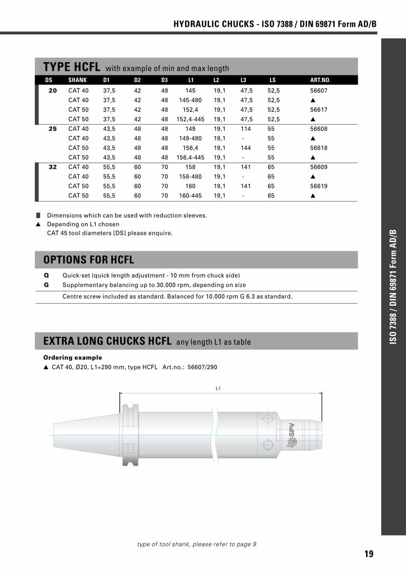
TYPE HCFL with example of min and max length
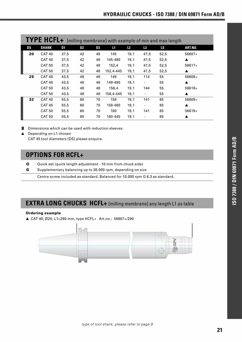
20 CAT 40 37,5 42 48 145 19,1 47,5 52,5 56607
CAT 40 37,5 42 48 145-480 19,1 47,5 52,5 ▲
CAT 50 37,5 42 48 152,4 19,1 47,5 52,5 56617
CAT 50 37,5 42 48 152,4-445 19,1 47,5 52,5 ▲
25 CAT 40 43,5 48 48 149 19,1 114 55 56608
CAT 40 43,5 48 48 149-480 19,1 - 55 ▲
CAT 50 43,5 48 48 156,4 19,1 144 55 56618
CAT 50 43,5 48 48 156,4-445 19,1 - 55 ▲
32 CAT 40 55,5 60 70 158 19,1 141 65 56609
CAT 40 55,5 60 70 158-480 19,1 - 65 ▲
CAT 50 55,5 60 70 160 19,1 141 65 56619
CAT 50 55,5 60 70 160-445 19,1 - 65 ▲
OPTIONS FOR HCFLQ Quick-set (quick length adjustment - 10 mm from chuck side)
G Supplementary balancing up to 30.000 rpm, depending on size
Centre screw included as standard. Balanced for 10.000 rpm G 6.3 as standard.
EXTRA LONG CHUCKS HCFL any length L1 as table
Ordering example
▲ CAT 40, Ø20, L1=290 mm, type HCFL Art.no.: 56607/290
L1
❙ Dimensions which can be used with reduction sleeves.▲ Depending on L1 chosen
CAT 45 tool diameters [DS] please enquire.
DS SHANK D1 D2 D3 L1 L2 L3 LS ART.NO.
20
HYDRAULIC CHUCKS - ISO 7388 / DIN 69871 Form AD/BIS
O 7
388
/DIN
698
71 F
orm
AD
/B
type of tool shank, please refer to page 9
EXTENDED CHUCK WITH MILLING MEMBRANE [+]
D1
Ds
L1
LsD
2
D3
L2 L3
D3
ø60
21
CAT 50 design Ø6 - 25
TYPE HCFL+ [milling membrane] with example of min and max lengthDS SHANK D1 D2 D3 L1 L2 L3 LS ART.NO.
6 CAT 40 23,5 26 48 145 19,1 43,5 37,5 56600+
CAT 40 23,5 26 48 145-480 19,1 43,5 37,5 ▲
CAT 50 23,5 26 48 152,4 19,1 43,5 37,5 56610+
CAT 50 23,5 26 48 152,4-445 19,1 43,5 37,5 ▲
8 CAT 40 23,5 28 48 145 19,1 43,5 37,5 56601+
CAT 40 23,5 28 48 145-480 19,1 43,5 37,5 ▲
CAT 50 23,5 28 48 152,4 19,1 43,5 37,5 56611+
CAT 50 23,5 28 48 152,4-445 19,1 43,5 37,5 ▲
10 CAT 40 25,5 30 48 145 19,1 43,5 42,5 56602+
CAT 40 25,5 30 48 145-480 19,1 43,5 42,5 ▲
CAT 50 25,5 30 48 152,4 19,1 43,5 42,5 56612+
CAT 50 25,5 30 48 152,4-445 19,1 43,5 42,5 ▲
12 CAT 40 27,5 32 48 145 19,1 44,5 47,5 56603+
CAT 40 27,5 32 48 145-480 19,1 44,5 47,5 ▲
CAT 50 27,5 32 48 152,4 19,1 44,5 47,5 56613+
CAT 50 27,5 32 48 152,4-445 19,1 44,5 47,5 ▲
14 CAT 40 29,5 34 48 145 19,1 47,5 52,5 56604+
CAT 40 29,5 34 48 145-480 19,1 47,5 52,5 ▲
CAT 50 29,5 34 48 152,4 19,1 47,5 52,5 56614+
CAT 50 29,5 34 48 152,4-445 19,1 47,5 52,5 ▲
16 CAT 40 33,5 38 48 145 19,1 47,5 52,5 56605+
CAT 40 33,5 38 48 145-480 19,1 47,5 52,5 ▲
CAT 50 33,5 38 48 152,4 19,1 47,5 52,5 56615+
CAT 50 33,5 38 48 152,4-445 19,1 47,5 52,5 ▲
18 CAT 40 35,5 40 48 145 19,1 47,5 52,5 56606+
CAT 40 35,5 40 48 145-480 19,1 47,5 52,5 ▲
CAT 50 35,5 40 48 152,4 19,1 47,5 52,5 56616+
CAT 50 35,5 40 48 152,4-445 19,1 47,5 52,5 ▲
21
HYDRAULIC CHUCKS - ISO 7388 / DIN 69871 Form AD/B
ISO
738
8 /D
IN 6
9871
For
m A
D/B
type of tool shank, please refer to page 9
L1
OPTIONS FOR HCFL+Q Quick-set (quick length adjustment - 10 mm from chuck side)
G Supplementary balancing up to 30.000 rpm, depending on size
Centre screw included as standard. Balanced for 10.000 rpm G 6.3 as standard.
EXTRA LONG CHUCKS HCFL+ [milling membrane] any length L1 as table
Ordering example
▲ CAT 40, Ø20, L1=290 mm, type HCFL+ Art.no.: 56607+/290
❙ Dimensions which can be used with reduction sleeves.▲ Depending on L1 chosen
CAT 45 tool diameters [DS] please enquire.
TYPE HCFL+ [milling membrane] with example of min and max length
20 CAT 40 37,5 42 48 145 19,1 47,5 52,5 56607+
CAT 40 37,5 42 48 145-480 19,1 47,5 52,5 ▲
CAT 50 37,5 42 48 152,4 19,1 47,5 52,5 56617+
CAT 50 37,5 42 48 152,4-445 19,1 47,5 52,5 ▲
25 CAT 40 43,5 48 48 149 19,1 114 55 56608+
CAT 40 43,5 48 48 149-480 19,1 - 55 ▲
CAT 50 43,5 48 48 156,4 19,1 144 55 56618+
CAT 50 43,5 48 48 156,4-445 19,1 - 55 ▲
32 CAT 40 55,5 60 70 158 19,1 141 65 56609+
CAT 40 55,5 60 70 158-480 19,1 - 65 ▲
CAT 50 55,5 60 70 160 19,1 141 65 56619+
CAT 50 55,5 60 70 160-445 19,1 - 65 ▲
DS SHANK D1 D2 D3 L1 L2 L3 LS ART.NO.
22
HYDRAULIC CHUCKS - ISO 7388 / DIN 69871 Form AD/BIS
O 7
388
/DIN
698
71 F
orm
AD
/B
type of tool shank, please refer to page 9
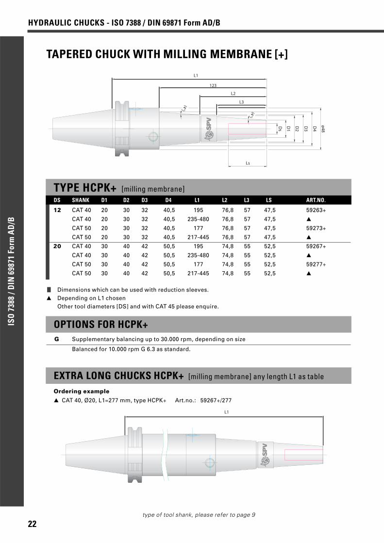
TAPERED CHUCK WITH MILLING MEMBRANE [+]
TYPE HCPK+ [milling membrane]
12 CAT 40 20 30 32 40,5 195 76,8 57 47,5 59263+
CAT 40 20 30 32 40,5 235-480 76,8 57 47,5 ▲
CAT 50 20 30 32 40,5 177 76,8 57 47,5 59273+
CAT 50 20 30 32 40,5 217-445 76,8 57 47,5 ▲
20 CAT 40 30 40 42 50,5 195 74,8 55 52,5 59267+
CAT 40 30 40 42 50,5 235-480 74,8 55 52,5 ▲
CAT 50 30 40 42 50,5 177 74,8 55 52,5 59277+
CAT 50 30 40 42 50,5 217-445 74,8 55 52,5 ▲
D1
Ds
L1
Ls
D2
D3
L2
L3
D4
ø48
123
(4°)
(4°)
EXTRA LONG CHUCKS HCPK+ [milling membrane] any length L1 as table
Ordering example
▲ CAT 40, Ø20, L1=277 mm, type HCPK+ Art.no.: 59267+/277
L1
❙ Dimensions which can be used with reduction sleeves.▲ Depending on L1 chosen
Other tool diameters [DS] and with CAT 45 please enquire.
DS SHANK D1 D2 D3 D4 L1 L2 L3 LS ART.NO.
OPTIONS FOR HCPK+G Supplementary balancing up to 30.000 rpm, depending on size
Balanced for 10.000 rpm G 6.3 as standard.
23
HYDRAULIC CHUCKS - ISO 7388 / DIN 69871 Form AD/B
ISO
738
8 /D
IN 6
9871
For
m A
D/B
type of tool shank, please refer to page 9
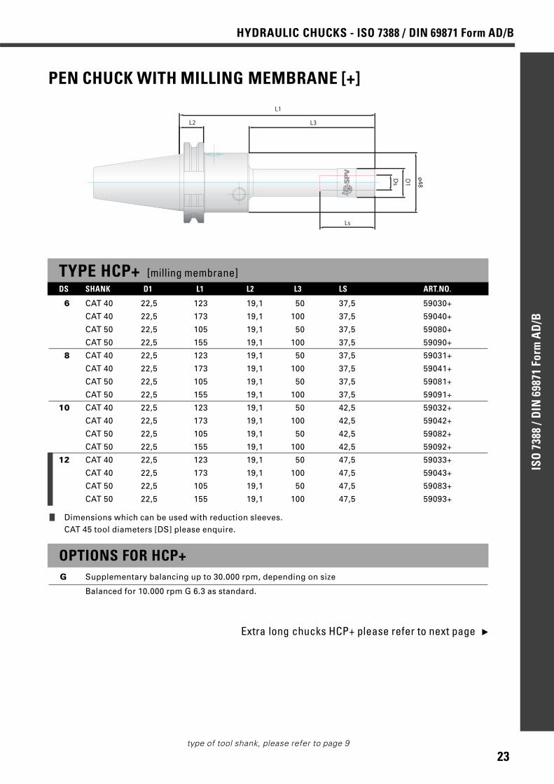
PEN CHUCK WITH MILLING MEMBRANE [+]
TYPE HCP+ [milling membrane] DS SHANK D1 L1 L2 L3 LS ART.NO.
6 CAT 40 22,5 123 19,1 50 37,5 59030+
CAT 40 22,5 173 19,1 100 37,5 59040+
CAT 50 22,5 105 19,1 50 37,5 59080+
CAT 50 22,5 155 19,1 100 37,5 59090+
8 CAT 40 22,5 123 19,1 50 37,5 59031+
CAT 40 22,5 173 19,1 100 37,5 59041+
CAT 50 22,5 105 19,1 50 37,5 59081+
CAT 50 22,5 155 19,1 100 37,5 59091+
10 CAT 40 22,5 123 19,1 50 42,5 59032+
CAT 40 22,5 173 19,1 100 42,5 59042+
CAT 50 22,5 105 19,1 50 42,5 59082+
CAT 50 22,5 155 19,1 100 42,5 59092+
12 CAT 40 22,5 123 19,1 50 47,5 59033+
CAT 40 22,5 173 19,1 100 47,5 59043+
CAT 50 22,5 105 19,1 50 47,5 59083+
CAT 50 22,5 155 19,1 100 47,5 59093+
D1
ø48
Ls
Ds
L2 L3
L1
❙ Dimensions which can be used with reduction sleeves.CAT 45 tool diameters [DS] please enquire.
OPTIONS FOR HCP+G Supplementary balancing up to 30.000 rpm, depending on size
Balanced for 10.000 rpm G 6.3 as standard.
Extra long chucks HCP+ please refer to next page ▲

24
HYDRAULIC CHUCKS - ISO 7388 / DIN 69871 Form AD/BIS
O 7
388
/DIN
698
71 F
orm
AD
/B
type of tool shank, please refer to page 9
EXTRA SHORT POWER CHUCK WITH MILLING MEMBRANE [+]
❙ Dimensions which can be used with reduction sleeves.
OPTIONS FOR HCK+G Supplementary balancing up to 30.000 rpm, depending on size
Centre screw included as standard. Balanced for 10.000 rpm G 6.3 as standard.
TYPE HCK+ [milling membrane] extra short length, extended torque
20 CAT 40 61 56 70 66122+
DS SHANK D1 L1 LS ART.NO.
D1
Ds
L1
Ls
EXTRA LONG CHUCKS HCP+ [milling membrane] any length L1 as table
Ordering example
CAT 40, Ø12, L1=255 mm, type HCP+ Art.no.: 59030+/255
Max L1: CAT 40 = 480 mm CAT 50 = 445 mm
L1
25
HYDRAULIC CHUCKS - HSK-A
HHSSKK
--AA
type of tool shank, please refer to page 9
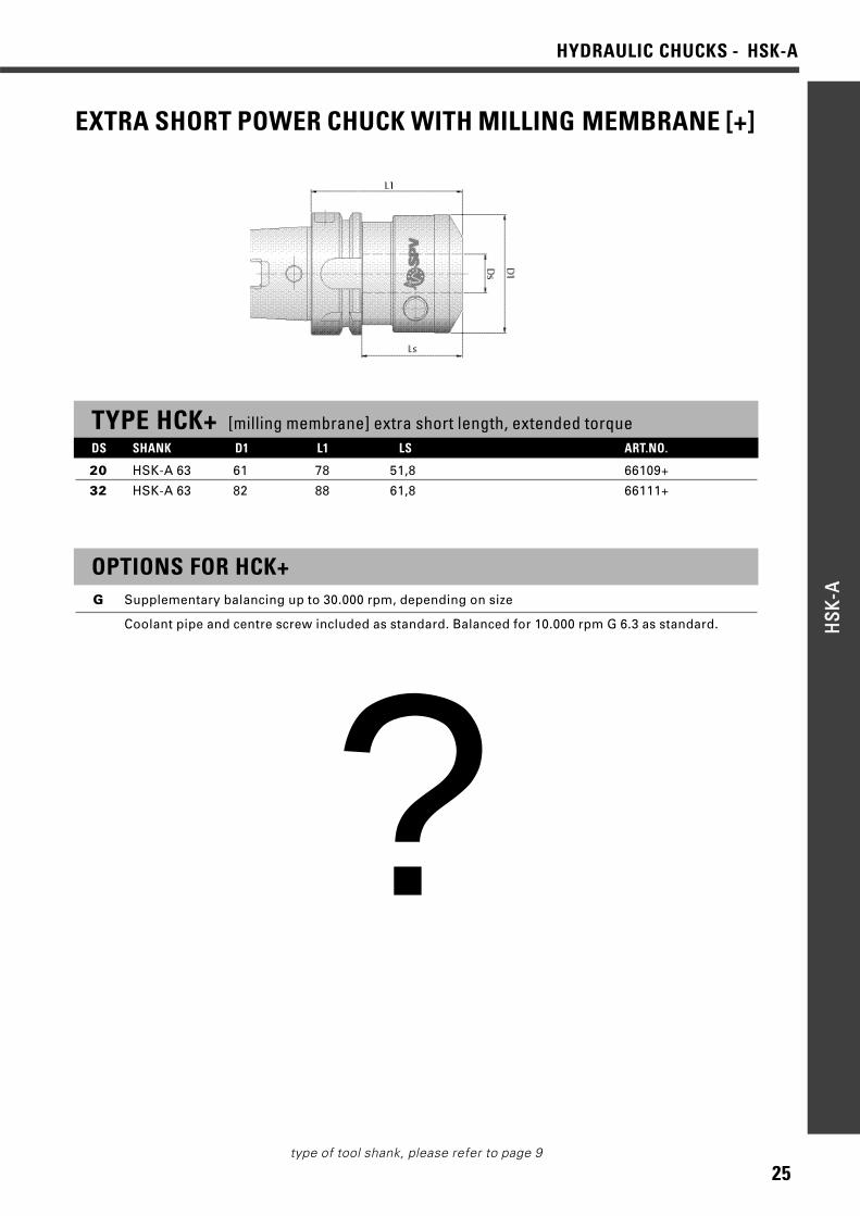
EXTRA SHORT POWER CHUCK WITH MILLING MEMBRANE [+]
OPTIONS FOR HCK+G Supplementary balancing up to 30.000 rpm, depending on size
Coolant pipe and centre screw included as standard. Balanced for 10.000 rpm G 6.3 as standard.
TYPE HCK+ [milling membrane] extra short length, extended torque
20 HSK-A 63 61 78 51,8 66109+
32 HSK-A 63 82 88 61,8 66111+
DS SHANK D1 L1 LS ART.NO.
?
26
HYDRAULIC CHUCKS - HSK-AHH
SSKK--AA
type of tool shank, please refer to page 9
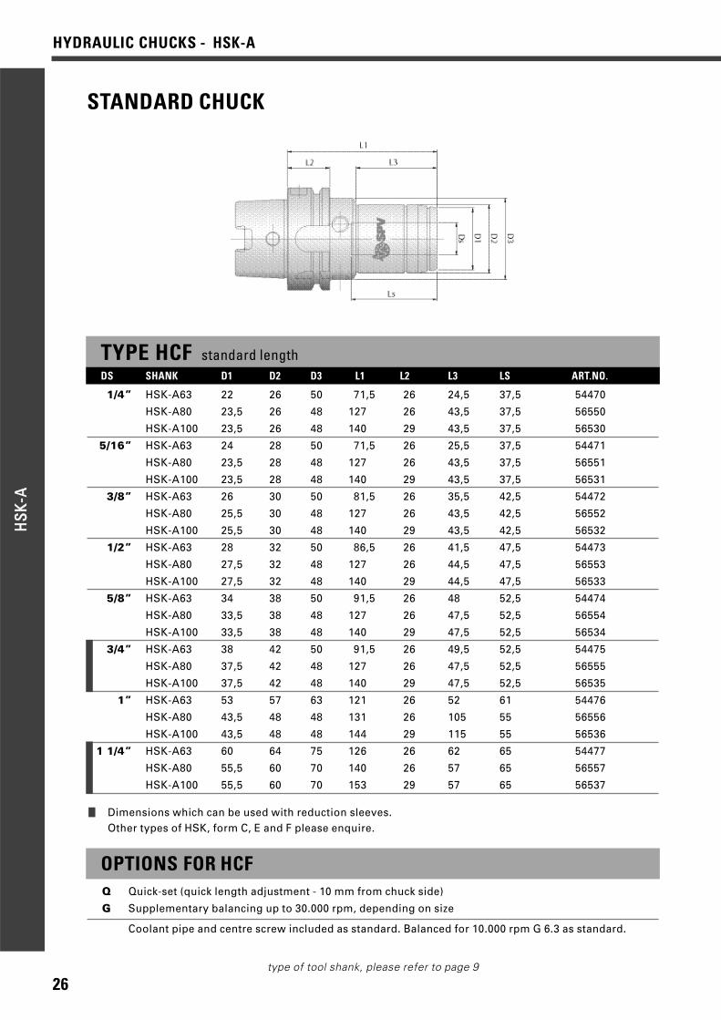
TYPE HCF standard lengthDS SHANK D1 D2 D3 L1 L2 L3 LS ART.NO.
1/4” HSK-A63 22 26 50 71,5 26 24,5 37,5 54470
HSK-A80 23,5 26 48 127 26 43,5 37,5 56550
HSK-A100 23,5 26 48 140 29 43,5 37,5 56530
5/16” HSK-A63 24 28 50 71,5 26 25,5 37,5 54471
HSK-A80 23,5 28 48 127 26 43,5 37,5 56551
HSK-A100 23,5 28 48 140 29 43,5 37,5 56531
3/8” HSK-A63 26 30 50 81,5 26 35,5 42,5 54472
HSK-A80 25,5 30 48 127 26 43,5 42,5 56552
HSK-A100 25,5 30 48 140 29 43,5 42,5 56532
1/2” HSK-A63 28 32 50 86,5 26 41,5 47,5 54473
HSK-A80 27,5 32 48 127 26 44,5 47,5 56553
HSK-A100 27,5 32 48 140 29 44,5 47,5 56533
5/8” HSK-A63 34 38 50 91,5 26 48 52,5 54474
HSK-A80 33,5 38 48 127 26 47,5 52,5 56554
HSK-A100 33,5 38 48 140 29 47,5 52,5 56534
3/4” HSK-A63 38 42 50 91,5 26 49,5 52,5 54475
HSK-A80 37,5 42 48 127 26 47,5 52,5 56555
HSK-A100 37,5 42 48 140 29 47,5 52,5 56535
1” HSK-A63 53 57 63 121 26 52 61 54476
HSK-A80 43,5 48 48 131 26 105 55 56556
HSK-A100 43,5 48 48 144 29 115 55 56536
1 1/4” HSK-A63 60 64 75 126 26 62 65 54477
HSK-A80 55,5 60 70 140 26 57 65 56557
HSK-A100 55,5 60 70 153 29 57 65 56537
OPTIONS FOR HCFQ Quick-set (quick length adjustment - 10 mm from chuck side)
G Supplementary balancing up to 30.000 rpm, depending on size
Coolant pipe and centre screw included as standard. Balanced for 10.000 rpm G 6.3 as standard.
❙ Dimensions which can be used with reduction sleeves.Other types of HSK, form C, E and F please enquire.
STANDARD CHUCK
27
HYDRAULIC CHUCKS - HSK-A
HHSSKK
--AA
type of tool shank, please refer to page 9
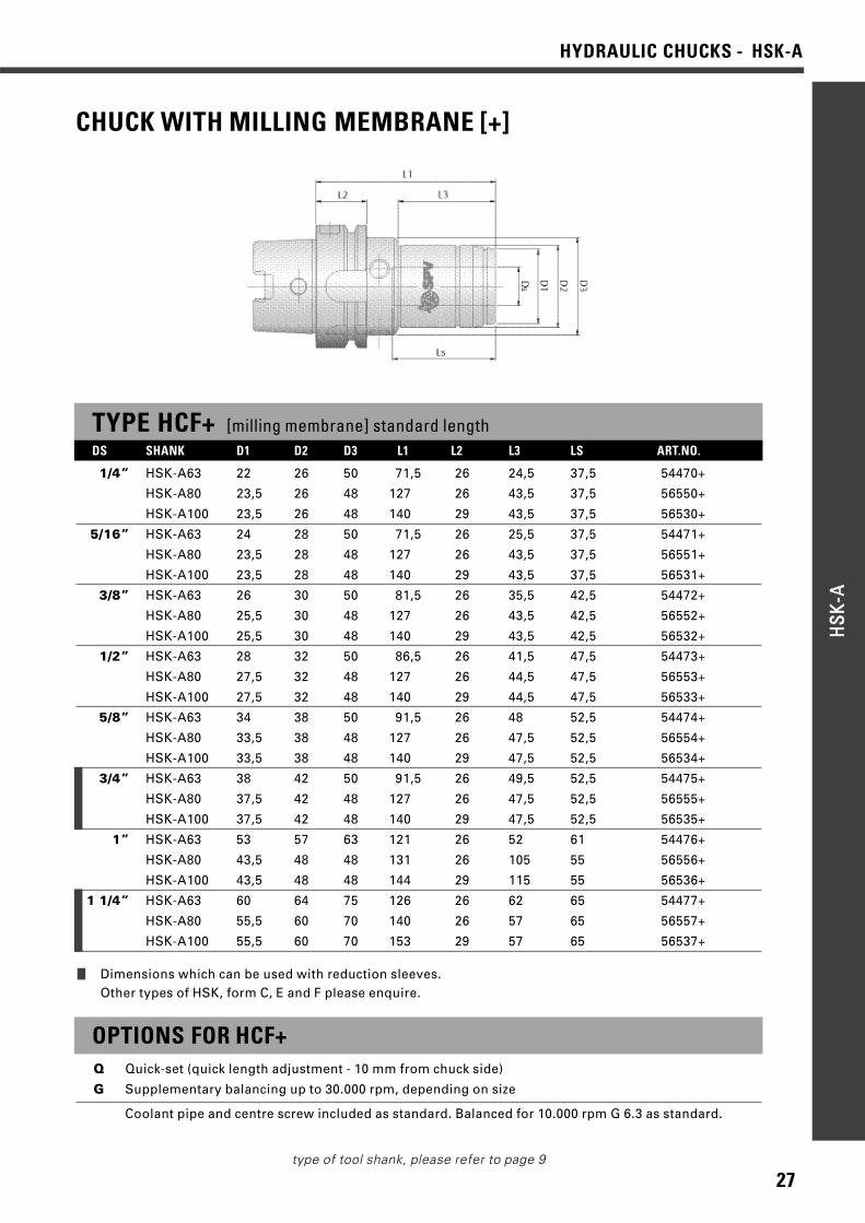
TYPE HCF+ [milling membrane] standard lengthDS SHANK D1 D2 D3 L1 L2 L3 LS ART.NO.
1/4” HSK-A63 22 26 50 71,5 26 24,5 37,5 54470+
HSK-A80 23,5 26 48 127 26 43,5 37,5 56550+
HSK-A100 23,5 26 48 140 29 43,5 37,5 56530+
5/16” HSK-A63 24 28 50 71,5 26 25,5 37,5 54471+
HSK-A80 23,5 28 48 127 26 43,5 37,5 56551+
HSK-A100 23,5 28 48 140 29 43,5 37,5 56531+
3/8” HSK-A63 26 30 50 81,5 26 35,5 42,5 54472+
HSK-A80 25,5 30 48 127 26 43,5 42,5 56552+
HSK-A100 25,5 30 48 140 29 43,5 42,5 56532+
1/2” HSK-A63 28 32 50 86,5 26 41,5 47,5 54473+
HSK-A80 27,5 32 48 127 26 44,5 47,5 56553+
HSK-A100 27,5 32 48 140 29 44,5 47,5 56533+
5/8” HSK-A63 34 38 50 91,5 26 48 52,5 54474+
HSK-A80 33,5 38 48 127 26 47,5 52,5 56554+
HSK-A100 33,5 38 48 140 29 47,5 52,5 56534+
3/4” HSK-A63 38 42 50 91,5 26 49,5 52,5 54475+
HSK-A80 37,5 42 48 127 26 47,5 52,5 56555+
HSK-A100 37,5 42 48 140 29 47,5 52,5 56535+
1” HSK-A63 53 57 63 121 26 52 61 54476+
HSK-A80 43,5 48 48 131 26 105 55 56556+
HSK-A100 43,5 48 48 144 29 115 55 56536+
1 1/4” HSK-A63 60 64 75 126 26 62 65 54477+
HSK-A80 55,5 60 70 140 26 57 65 56557+
HSK-A100 55,5 60 70 153 29 57 65 56537+
OPTIONS FOR HCF+Q Quick-set (quick length adjustment - 10 mm from chuck side)
G Supplementary balancing up to 30.000 rpm, depending on size
Coolant pipe and centre screw included as standard. Balanced for 10.000 rpm G 6.3 as standard.
❙ Dimensions which can be used with reduction sleeves.Other types of HSK, form C, E and F please enquire.
CHUCK WITH MILLING MEMBRANE [+]
28
HYDRAULIC CHUCKS - HSK-AHH
SSKK--AA
type of tool shank, please refer to page 9
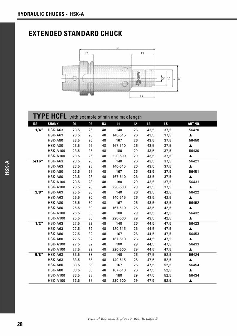
EXTENDED STANDARD CHUCK
TYPE HCFL with example of min and max lengthDS SHANK D1 D2 D3 L1 L2 L3 LS ART.NO.
1/4” HSK-A63 23,5 26 48 140 26 43,5 37,5 56420HSK-A63 23,5 26 48 140-515 26 43,5 37,5 ▲
HSK-A80 23,5 26 48 167 26 43,5 37,5 56450HSK-A80 23,5 26 48 167-510 26 43,5 37,5 ▲
HSK-A100 23,5 26 48 180 29 43,5 37,5 56430HSK-A100 23,5 26 48 220-500 29 43,5 37,5 ▲
5/16” HSK-A63 23,5 28 48 140 26 43,5 37,5 56421HSK-A63 23,5 28 48 140-515 26 43,5 37,5 ▲
HSK-A80 23,5 28 48 167 26 43,5 37,5 56451HSK-A80 23,5 28 48 167-510 26 43,5 37,5 ▲
HSK-A100 23,5 28 48 180 29 43,5 37,5 56431HSK-A100 23,5 28 48 220-500 29 43,5 37,5 ▲
3/8” HSK-A63 25,5 30 48 140 26 43,5 42,5 56422HSK-A63 25,5 30 48 140-515 26 43,5 42,5 ▲
HSK-A80 25,5 30 48 167 26 43,5 42,5 56452HSK-A80 25,5 30 48 167-510 26 43,5 42,5 ▲
HSK-A100 25,5 30 48 180 29 43,5 42,5 56432HSK-A100 25,5 30 48 220-500 29 43,5 42,5 ▲
1/2” HSK-A63 27,5 32 48 140 26 44,5 47,5 56423HSK-A63 27,5 32 48 180-515 26 44,5 47,5 ▲
HSK-A80 27,5 32 48 167 26 44,5 47,5 56453HSK-A80 27,5 32 48 167-510 26 44,5 47,5 ▲
HSK-A100 27,5 32 48 180 29 44,5 47,5 56433HSK-A100 27,5 32 48 220-500 29 44,5 47,5 ▲
5/8” HSK-A63 33,5 38 48 140 26 47,5 52,5 56424HSK-A63 33,5 38 48 140-515 26 47,5 52,5 ▲
HSK-A80 33,5 38 48 167 26 47,5 52,5 56454HSK-A80 33,5 38 48 167-510 26 47,5 52,5 ▲
HSK-A100 33,5 38 48 180 29 47,5 52,5 56434HSK-A100 33,5 38 48 220-500 29 47,5 52,5 ▲

29
HYDRAULIC CHUCKS - HSK-A
HHSSKK
--AA
type of tool shank, please refer to page 9
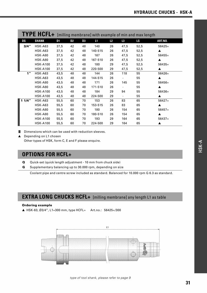
TYPE HCFL with example of min and max length
3/4” HSK-A63 37,5 42 48 140 26 47,5 52,5 56425HSK-A63 37,5 42 48 140-515 26 47,5 52,5 ▲
HSK-A80 37,5 42 48 167 26 47,5 52,5 56455HSK-A80 37,5 42 48 167-510 26 47,5 52,5 ▲
HSK-A100 37,5 42 48 180 29 47,5 52,5 56435HSK-A100 37,5 42 48 220-500 29 47,5 52,5 ▲
1” HSK-A63 43,5 48 48 144 26 118 55 56426HSK-A63 43,5 48 48 144-515 26 - 55 ▲
HSK-A80 43,5 48 48 171 26 145 55 56456HSK-A80 43,5 48 48 171-510 26 - 55 ▲
HSK-A100 43,5 48 48 184 29 94 55 56436HSK-A100 43,5 48 48 224-500 29 - 55 ▲
1 1/4” HSK-A63 55,5 60 70 153 26 83 65 56427HSK-A63 55,5 60 70 153-515 26 83 65 ▲
HSK-A80 55,5 60 70 180 26 154 65 56457HSK-A80 55,5 60 70 180-510 26 154 65 ▲
HSK-A100 55,5 60 70 193 29 164 65 56437HSK-A100 55,5 60 70 224-500 29 164 65 ▲
DS SHANK D1 D2 D3 L1 L2 L3 LS ART.NO.
OPTIONS FOR HCFLQ Quick-set (quick length adjustment - 10 mm from chuck side)
G Supplementary balancing up to 30.000 rpm, depending on size
Coolant pipe and centre screw included as standard. Balanced for 10.000 rpm G 6.3 as standard.
EXTRA LONG CHUCKS HCFL any length L1 as table
Ordering example
▲ HSK-63, Ø3/4”, L1=300 mm, type HCFL Art.no.: 56425/300
❙ Dimensions which can be used with reduction sleeves.▲ Depending on L1 chosen
Other types of HSK, form C, E and F please enquire.
30
HYDRAULIC CHUCKS - HSK-AHH
SSKK--AA
type of tool shank, please refer to page 9
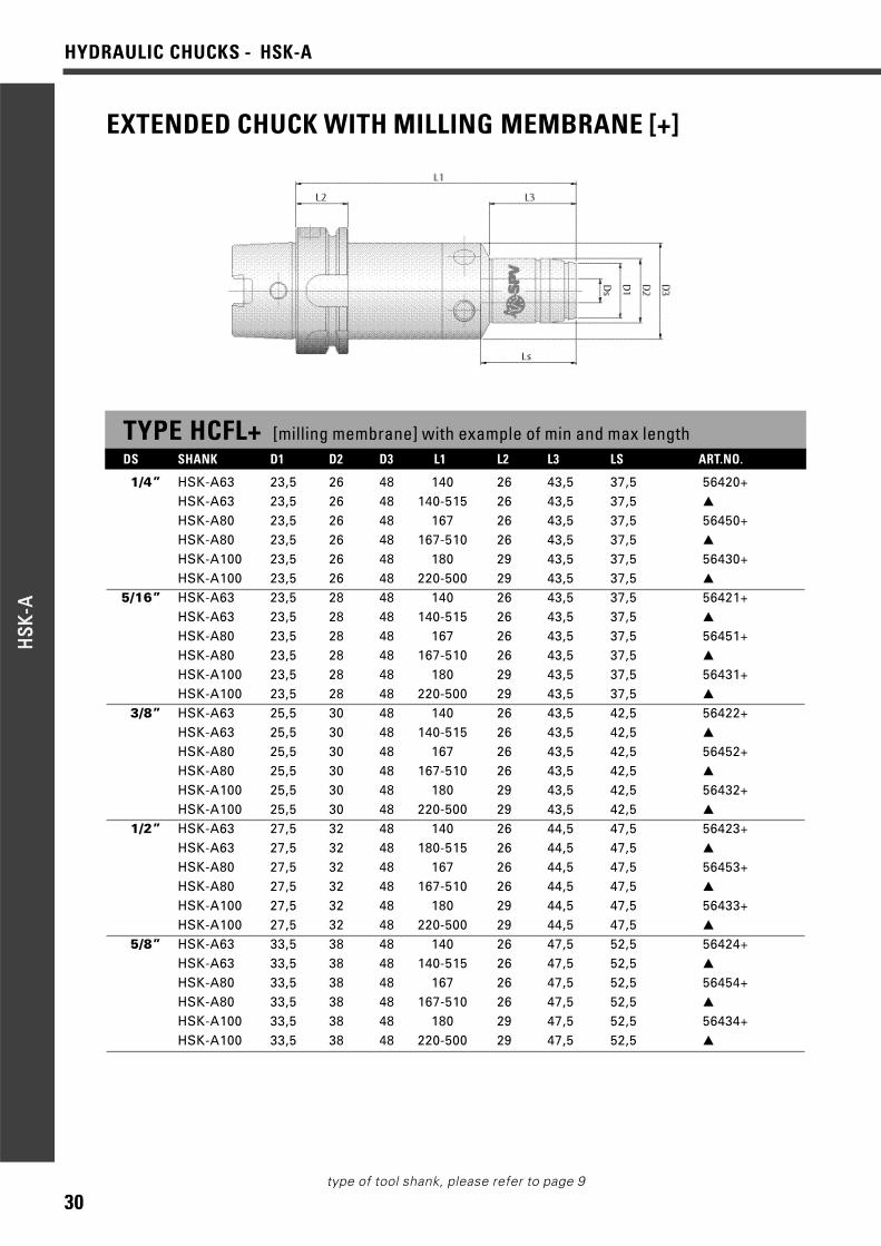
EXTENDED CHUCK WITH MILLING MEMBRANE [+]
TYPE HCFL+ [milling membrane] with example of min and max lengthDS SHANK D1 D2 D3 L1 L2 L3 LS ART.NO.
1/4” HSK-A63 23,5 26 48 140 26 43,5 37,5 56420+HSK-A63 23,5 26 48 140-515 26 43,5 37,5 ▲
HSK-A80 23,5 26 48 167 26 43,5 37,5 56450+HSK-A80 23,5 26 48 167-510 26 43,5 37,5 ▲
HSK-A100 23,5 26 48 180 29 43,5 37,5 56430+HSK-A100 23,5 26 48 220-500 29 43,5 37,5 ▲
5/16” HSK-A63 23,5 28 48 140 26 43,5 37,5 56421+HSK-A63 23,5 28 48 140-515 26 43,5 37,5 ▲
HSK-A80 23,5 28 48 167 26 43,5 37,5 56451+HSK-A80 23,5 28 48 167-510 26 43,5 37,5 ▲
HSK-A100 23,5 28 48 180 29 43,5 37,5 56431+HSK-A100 23,5 28 48 220-500 29 43,5 37,5 ▲
3/8” HSK-A63 25,5 30 48 140 26 43,5 42,5 56422+HSK-A63 25,5 30 48 140-515 26 43,5 42,5 ▲
HSK-A80 25,5 30 48 167 26 43,5 42,5 56452+HSK-A80 25,5 30 48 167-510 26 43,5 42,5 ▲
HSK-A100 25,5 30 48 180 29 43,5 42,5 56432+HSK-A100 25,5 30 48 220-500 29 43,5 42,5 ▲
1/2” HSK-A63 27,5 32 48 140 26 44,5 47,5 56423+HSK-A63 27,5 32 48 180-515 26 44,5 47,5 ▲
HSK-A80 27,5 32 48 167 26 44,5 47,5 56453+HSK-A80 27,5 32 48 167-510 26 44,5 47,5 ▲
HSK-A100 27,5 32 48 180 29 44,5 47,5 56433+HSK-A100 27,5 32 48 220-500 29 44,5 47,5 ▲
5/8” HSK-A63 33,5 38 48 140 26 47,5 52,5 56424+HSK-A63 33,5 38 48 140-515 26 47,5 52,5 ▲
HSK-A80 33,5 38 48 167 26 47,5 52,5 56454+HSK-A80 33,5 38 48 167-510 26 47,5 52,5 ▲
HSK-A100 33,5 38 48 180 29 47,5 52,5 56434+HSK-A100 33,5 38 48 220-500 29 47,5 52,5 ▲
31
HYDRAULIC CHUCKS - HSK-A
HHSSKK
--AA
type of tool shank, please refer to page 9
TYPE HCFL+ [milling membrane] with example of min and max length
3/4” HSK-A63 37,5 42 48 140 26 47,5 52,5 56425+HSK-A63 37,5 42 48 140-515 26 47,5 52,5 ▲
HSK-A80 37,5 42 48 167 26 47,5 52,5 56455+HSK-A80 37,5 42 48 167-510 26 47,5 52,5 ▲
HSK-A100 37,5 42 48 180 29 47,5 52,5 56435+HSK-A100 37,5 42 48 220-500 29 47,5 52,5 ▲
1” HSK-A63 43,5 48 48 144 26 118 55 56426+HSK-A63 43,5 48 48 144-515 26 - 55 ▲
HSK-A80 43,5 48 48 171 26 145 55 56456+HSK-A80 43,5 48 48 171-510 26 - 55 ▲
HSK-A100 43,5 48 48 184 29 94 55 56436+HSK-A100 43,5 48 48 224-500 29 - 55 ▲
1 1/4” HSK-A63 55,5 60 70 153 26 83 65 56427+HSK-A63 55,5 60 70 153-515 26 83 65 ▲
HSK-A80 55,5 60 70 180 26 154 65 56457+HSK-A80 55,5 60 70 180-510 26 154 65 ▲
HSK-A100 55,5 60 70 193 29 164 65 56437+HSK-A100 55,5 60 70 224-500 29 164 65 ▲
DS SHANK D1 D2 D3 L1 L2 L3 LS ART.NO.
OPTIONS FOR HCFL+Q Quick-set (quick length adjustment - 10 mm from chuck side)
G Supplementary balancing up to 30.000 rpm, depending on size
Coolant pipe and centre screw included as standard. Balanced for 10.000 rpm G 6.3 as standard.
EXTRA LONG CHUCKS HCFL+ [milling membrane] any length L1 as table
Ordering example
▲ HSK-63, Ø3/4”, L1=300 mm, type HCFL+ Art.no.: 56425+/300
❙ Dimensions which can be used with reduction sleeves.▲ Depending on L1 chosen
Other types of HSK, form C, E and F please enquire.
32
HYDRAULIC CHUCKS - BT-MASBB
TT--MM
AASS
type of tool shank, please refer to page 9
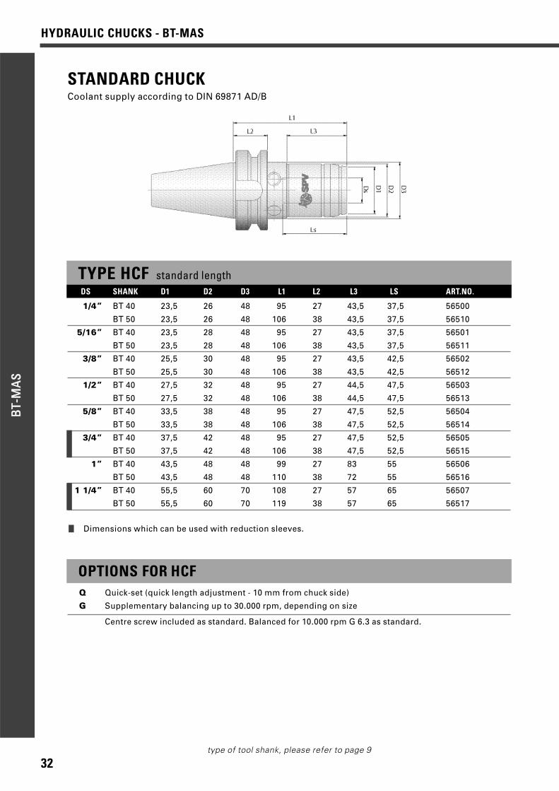
STANDARD CHUCKCoolant supply according to DIN 69871 AD/B
TYPE HCF standard lengthDS SHANK D1 D2 D3 L1 L2 L3 LS ART.NO.
1/4” BT 40 23,5 26 48 95 27 43,5 37,5 56500
BT 50 23,5 26 48 106 38 43,5 37,5 56510
5/16” BT 40 23,5 28 48 95 27 43,5 37,5 56501
BT 50 23,5 28 48 106 38 43,5 37,5 56511
3/8” BT 40 25,5 30 48 95 27 43,5 42,5 56502
BT 50 25,5 30 48 106 38 43,5 42,5 56512
1/2” BT 40 27,5 32 48 95 27 44,5 47,5 56503
BT 50 27,5 32 48 106 38 44,5 47,5 56513
5/8” BT 40 33,5 38 48 95 27 47,5 52,5 56504
BT 50 33,5 38 48 106 38 47,5 52,5 56514
3/4” BT 40 37,5 42 48 95 27 47,5 52,5 56505
BT 50 37,5 42 48 106 38 47,5 52,5 56515
1” BT 40 43,5 48 48 99 27 83 55 56506
BT 50 43,5 48 48 110 38 72 55 56516
1 1/4” BT 40 55,5 60 70 108 27 57 65 56507
BT 50 55,5 60 70 119 38 57 65 56517
OPTIONS FOR HCFQ Quick-set (quick length adjustment - 10 mm from chuck side)
G Supplementary balancing up to 30.000 rpm, depending on size
Centre screw included as standard. Balanced for 10.000 rpm G 6.3 as standard.
❙ Dimensions which can be used with reduction sleeves.
33
HYDRAULIC CHUCKS - BT-MAS
BBTT--
MMAA
SS
type of tool shank, please refer to page 9
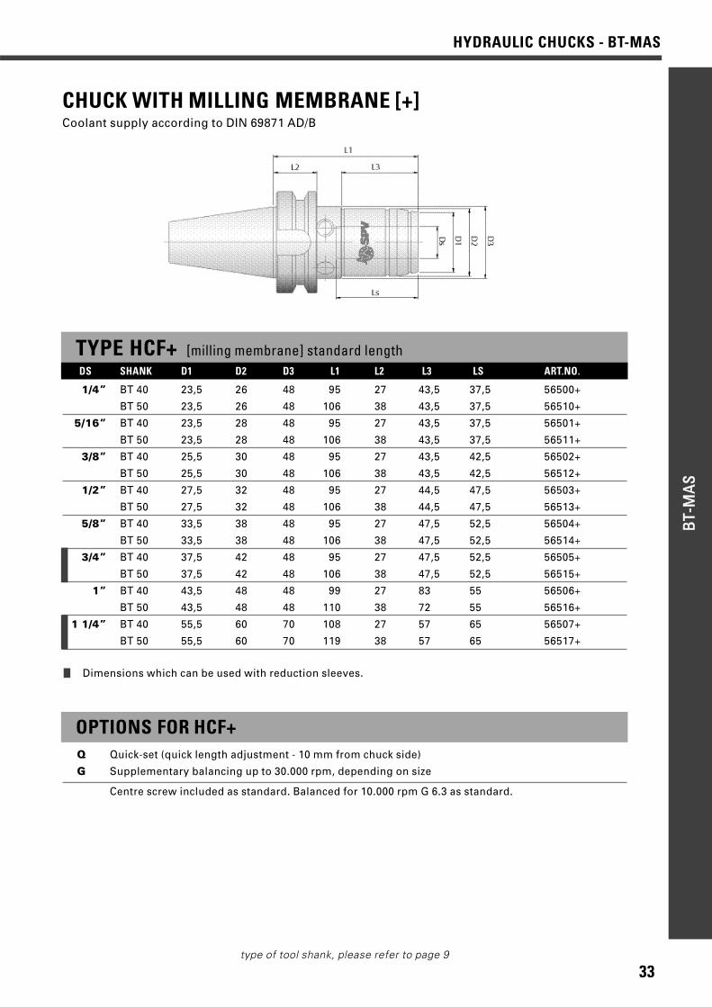
CHUCK WITH MILLING MEMBRANE [+]Coolant supply according to DIN 69871 AD/B
TYPE HCF+ [milling membrane] standard lengthDS SHANK D1 D2 D3 L1 L2 L3 LS ART.NO.
1/4” BT 40 23,5 26 48 95 27 43,5 37,5 56500+
BT 50 23,5 26 48 106 38 43,5 37,5 56510+
5/16” BT 40 23,5 28 48 95 27 43,5 37,5 56501+
BT 50 23,5 28 48 106 38 43,5 37,5 56511+
3/8” BT 40 25,5 30 48 95 27 43,5 42,5 56502+
BT 50 25,5 30 48 106 38 43,5 42,5 56512+
1/2” BT 40 27,5 32 48 95 27 44,5 47,5 56503+
BT 50 27,5 32 48 106 38 44,5 47,5 56513+
5/8” BT 40 33,5 38 48 95 27 47,5 52,5 56504+
BT 50 33,5 38 48 106 38 47,5 52,5 56514+
3/4” BT 40 37,5 42 48 95 27 47,5 52,5 56505+
BT 50 37,5 42 48 106 38 47,5 52,5 56515+
1” BT 40 43,5 48 48 99 27 83 55 56506+
BT 50 43,5 48 48 110 38 72 55 56516+
1 1/4” BT 40 55,5 60 70 108 27 57 65 56507+
BT 50 55,5 60 70 119 38 57 65 56517+
OPTIONS FOR HCF+Q Quick-set (quick length adjustment - 10 mm from chuck side)
G Supplementary balancing up to 30.000 rpm, depending on size
Centre screw included as standard. Balanced for 10.000 rpm G 6.3 as standard.
❙ Dimensions which can be used with reduction sleeves.
34
HYDRAULIC CHUCKS - BT-MASBB
TT--MM
AASS
type of tool shank, please refer to page 9
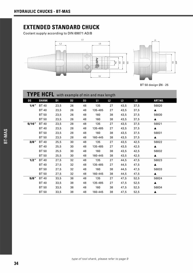
TYPE HCFL with example of min and max lengthDS SHANK D1 D2 D3 L1 L2 L3 LS ART.NO.
1/4” BT 40 23,5 26 48 135 27 43,5 37,5 56820
BT 40 23,5 26 48 135-485 27 43,5 37,5 ▲
BT 50 23,5 26 48 160 38 43,5 37,5 56830
BT 50 23,5 26 48 160 38 43,5 37,5 ▲
5/16” BT 40 23,5 28 48 135 27 43,5 37,5 56821
BT 40 23,5 28 48 135-485 27 43,5 37,5 ▲
BT 50 23,5 28 48 160 38 43,5 37,5 56831
BT 50 23,5 28 48 160-445 38 43,5 37,5 ▲
3/8” BT 40 25,5 30 48 135 27 43,5 42,5 56822
BT 40 25,5 30 48 135-485 27 43,5 42,5 ▲
BT 50 25,5 30 48 160 38 43,5 42,5 56832
BT 50 25,5 30 48 160-445 38 43,5 42,5 ▲
1/2” BT 40 27,5 32 48 135 27 44,5 47,5 56823
BT 40 27,5 32 48 135-485 27 44,5 47,5 ▲
BT 50 27,5 32 48 160 38 44,5 47,5 56833
BT 50 27,5 32 48 160-445 38 44,5 47,5 ▲
5/8” BT 40 33,5 38 48 135 27 47,5 52,5 56824
BT 40 33,5 38 48 135-485 27 47,5 52,5 ▲
BT 50 33,5 38 48 160 38 47,5 52,5 56834
BT 50 33,5 38 48 160-445 38 47,5 52,5 ▲
EXTENDED STANDARD CHUCKCoolant supply according to DIN 69871 AD/B
BT 50 design Ø6 - 25
35
HYDRAULIC CHUCKS - BT-MAS
BBTT--
MMAA
SS
type of tool shank, please refer to page 9
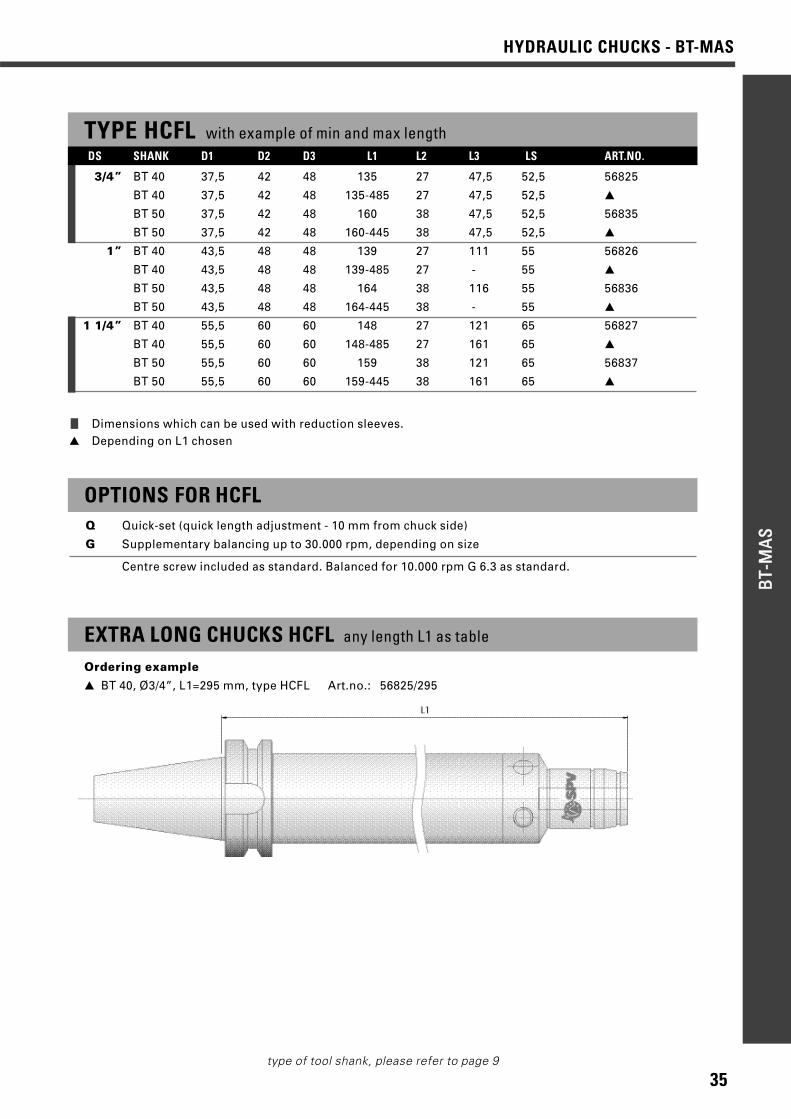
TYPE HCFL with example of min and max length
3/4” BT 40 37,5 42 48 135 27 47,5 52,5 56825
BT 40 37,5 42 48 135-485 27 47,5 52,5 ▲
BT 50 37,5 42 48 160 38 47,5 52,5 56835
BT 50 37,5 42 48 160-445 38 47,5 52,5 ▲
1” BT 40 43,5 48 48 139 27 111 55 56826
BT 40 43,5 48 48 139-485 27 - 55 ▲
BT 50 43,5 48 48 164 38 116 55 56836
BT 50 43,5 48 48 164-445 38 - 55 ▲
1 1/4” BT 40 55,5 60 60 148 27 121 65 56827
BT 40 55,5 60 60 148-485 27 161 65 ▲
BT 50 55,5 60 60 159 38 121 65 56837
BT 50 55,5 60 60 159-445 38 161 65 ▲
OPTIONS FOR HCFLQ Quick-set (quick length adjustment - 10 mm from chuck side)
G Supplementary balancing up to 30.000 rpm, depending on size
Centre screw included as standard. Balanced for 10.000 rpm G 6.3 as standard.
EXTRA LONG CHUCKS HCFL any length L1 as table
Ordering example
▲ BT 40, Ø3/4”, L1=295 mm, type HCFL Art.no.: 56825/295
❙ Dimensions which can be used with reduction sleeves.▲ Depending on L1 chosen
DS SHANK D1 D2 D3 L1 L2 L3 LS ART.NO.

36
HYDRAULIC CHUCKS - BT-MASBB
TT--MM
AASS
type of tool shank, please refer to page 9
EXTENDED CHUCK WITH MILLING MEMBRANE [+]Coolant supply according to DIN 69871 AD/B
BT 50 design Ø6 - 25
TYPE HCFL+ [milling membrane] with example of min and max lengthDS SHANK D1 D2 D3 L1 L2 L3 LS ART.NO.
1/4” BT 40 23,5 26 48 135 27 43,5 37,5 56820+
BT 40 23,5 26 48 135-485 27 43,5 37,5 ▲
BT 50 23,5 26 48 160 38 43,5 37,5 56830+
BT 50 23,5 26 48 160 38 43,5 37,5 ▲
5/16” BT 40 23,5 28 48 135 27 43,5 37,5 56821+
BT 40 23,5 28 48 135-485 27 43,5 37,5 ▲
BT 50 23,5 28 48 160 38 43,5 37,5 56831+
BT 50 23,5 28 48 160-445 38 43,5 37,5 ▲
3/8” BT 40 25,5 30 48 135 27 43,5 42,5 56822+
BT 40 25,5 30 48 135-485 27 43,5 42,5 ▲
BT 50 25,5 30 48 160 38 43,5 42,5 56832+
BT 50 25,5 30 48 160-445 38 43,5 42,5 ▲
1/2” BT 40 27,5 32 48 135 27 44,5 47,5 56823+
BT 40 27,5 32 48 135-485 27 44,5 47,5 ▲
BT 50 27,5 32 48 160 38 44,5 47,5 56833+
BT 50 27,5 32 48 160-445 38 44,5 47,5 ▲
5/8” BT 40 33,5 38 48 135 27 47,5 52,5 56824+
BT 40 33,5 38 48 135-485 27 47,5 52,5 ▲
BT 50 33,5 38 48 160 38 47,5 52,5 56834+
BT 50 33,5 38 48 160-445 38 47,5 52,5 ▲

37
HYDRAULIC CHUCKS - BT-MAS
BBTT--
MMAA
SS
type of tool shank, please refer to page 9
TYPE HCFL+ [milling membrane] with example of min and max length
3/4” BT 40 37,5 42 48 135 27 47,5 52,5 56825+
BT 40 37,5 42 48 135-485 27 47,5 52,5 ▲
BT 50 37,5 42 48 160 38 47,5 52,5 56835+
BT 50 37,5 42 48 160-445 38 47,5 52,5 ▲
1” BT 40 43,5 48 48 139 27 111 55 56826+
BT 40 43,5 48 48 139-485 27 - 55 ▲
BT 50 43,5 48 48 164 38 116 55 56836+
BT 50 43,5 48 48 164-445 38 - 55 ▲
1 1/4” BT 40 55,5 60 60 148 27 121 65 56827+
BT 40 55,5 60 60 148-485 27 161 65 ▲
BT 50 55,5 60 60 159 38 121 65 56837+
BT 50 55,5 60 60 159-445 38 161 65 ▲
OPTIONS FOR HCFL+Q Quick-set (quick length adjustment - 10 mm from chuck side)
G Supplementary balancing up to 30.000 rpm, depending on size
Centre screw included as standard. Balanced for 10.000 rpm G 6.3 as standard.
EXTRA LONG CHUCKS HCFL+ any length L1 as table
Ordering example
▲ BT 40, Ø3/4”, L1=295 mm, type HCFL+ Art.no.: 56825+/295
❙ Dimensions which can be used with reduction sleeves.▲ Depending on L1 chosen
DS SHANK D1 D2 D3 L1 L2 L3 LS ART.NO.

38
REDUCTION SLEEVESRE
DU
CTIO
NSL
EEVE
S
REDUCTION SLEEVES
Standard sleevesD DS L Type ART.NO.
12 3 46 C 684134 C 684145 A 684256 A 684268 A 68428
10 C 6842010 B 68430
20 3 53 C 669294 C 669305 C 669316 A 658008 A 65801
10 A 6580212 A 6580314 A 6580416 A 65805
32 10 64,5 A 6580712 A 6580814 A 6580916 A 6581018 A 6581120 A 6581225 A 65813
With Quick-set [adjustable]D DS L Type ART.NO.
20 6 53 A 65800Q8 A 65801Q
10 A 65802Q12 A 65803Q14 A 65804Q
32 10 64,5 A 65807Q12 A 65808Q14 A 65809Q16 A 65810Q18 A 65811Q20 A 65812Q25 A 65813Q
40 16 71 A 66904Q20 A 66905Q25 A 66906Q32 A 66907Q
TYPE ASealed sleeve with rubber stop.Sleeves can be converted to unsealedby removing the rubber stop.
TYPE BSealed sleeve.With short slot length.
TYPE CUnsealed sleeve.With long slot length.
TORQUE MANDRELD L ART.NO.
6 65 668008 65 66801
10 69 6680212 74 6680314 74 66808
D L ART.NO.
16 77 6680418 77 6680920 81 6680525 85 6680632 92 66807
short slot length
long slot length
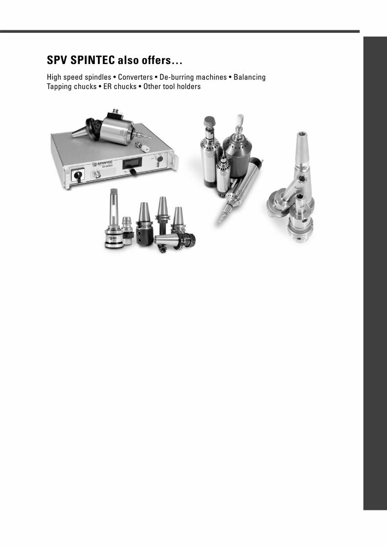
SPV SPINTEC also offers…High speed spindles • Converters • De-burring machines • BalancingTapping chucks • ER chucks • Other tool holders
Spintec AB is a family company which was formed in 1977
in Eskilstuna, with the aim of making and marketing high speed
electric machining spindles, plus converters and accessories for
the Swedish market and other industrialised countries.
Right from the start, the company aimed at marketing high quality
products and services, with a high technology content, and always
endeavoured to use the latest machine and appliance technology
in its own manufacture.
In the summer of 2003, it acquired SPV Tools as a measure to
widen its product range. SPV Tools was founded in 1933 and makes
very high precision tool holders for industry. Its products include
hydraulic chucks, threading tools and other tool holders. When
combined with Spintec products, this gives a full-range supplier of
equipment for industrial machining.
After SPV Tools was acquired, the SPV Spintec AB was formed.
These days, the SPV Spintec AB has become known as a problem-
solving collaboration partner, whose unique machining know-how
can offer customised solutions.
Technical consultation, quick service and reliable deliveries are
our hall-marks.
SPV SPINTEC ABBOX 303, SE-631 04 ESKILSTUNA, SWEDENVISITING ADDRESS Fabriksgatan 13, SE-633 46 EskilstunaTELEPHONE +46 16 12 54 70
+46 16 15 30 30TELEFAX +46 16 14 04 04
+46 16 51 34 64E-MAIL [email protected] www.spintec.se
© 2
005
SPV
SPIN
TEC
AB -
0506
.100
0 •
prod
uctio
n Gr
afis
k Vis
ion