hydraulic control, hd · unit dimensions hd.d / hd.g 34 hd1p with power control 39 unit dimensions...
TRANSCRIPT

Linear Motion andAssembly Technologies ServicePneumaticsHydraulics
Electric Drives and Controls
Technical Data Sheet
Hydraulic control,pilot pressure dependent HD
RA 92 080/06.06 1/56Replaces: 05.95
for the variable pumps(A)A4VSO and (A)A4VSG series 1 and 3(A)A4CSG series 3open and closed circuits
Features– Displacement control for the variable pumps (A)A4VSO,
(A)A4VSG and (A)A4CSG
– Control is pilot pressure dependent
– Different pilot pressure ranges available
– Optional pressure control
– Optional hydraulic power control
– Optional electrical control of pilot pressure
– Mechanical limitation of Vg min and Vg max
– Standard spring centering of control cylinder
– Loss of pilot pressure signal causes swivel back to center
– Mooring operation: enables swiveling over center and de-compression via the pump
Further information:
Variable pump (A)A4VSO Size 40...1000 RA 92050
Variable pump (A)A4VSG Size 40...1000 RA 92100
Variable pump (A)A4CSG Size 250...750 RA 92105
ISO Version Sizes 40...355 see RE 92080
ContentsOrdering code / Standard program 2
HD1/2/3 – Hydraulic control, pilot pressure dependent 4
Unit dimensions HD1/2/3 9
Pressure control 13
HD.A with pressure control on one side for port A 14
HD.GA with remote pressure control for port A 16
Unit dimensions HD.A / HD.GA 18
HD.B with pressure control on one side for port B 22
HD.GB with remote pressure control for port B 24
Unit dimensions HD.B / HD.GB 26
HD.D with pressure control for ports A and B 30
HD.G with remote pressure control for A and B 32
Unit dimensions HD.D / HD.G 34
HD1P with power control 39
Unit dimensions HD1P 41
HD1T with electrical control of pilot pressure 44
Unit dimensions HD1T 48
HD1U with power control and elec. control of pilot press. 51
Unit dimensions HD1U 52
General notes 56

2/56 Bosch Rexroth Corporation HD | RA 92 080/06.06
(A)A4 . . . HD . / –01 02 03 04 05 06 07 08 09 10 11 12 13 14 15
Ordering code / Standard program
01 Hydraulic fluid (for detailed information see RA 92050, RA 92100 or RA 92105)
Axial piston unit / type of operation
02
Swash plate design, variable / pump, open circuit (see RA 92050) Size 40...355 AA4VSO
Size 500...1000 A4VSO
Swash plate design, variable / pump, closed circuit (see RA92100) Size 40...355 AA4VSG
Size 500...1000 A4VSG
Compact unit swash plate design, variable / pump, closed circuit (see RA 92105) Size 250 and 355 AA4CSG
Size 500 and 750 A4CSG
Size 40 71 125 180 250 355 500 750 1000
03Displacement Vg max in3/rev 2.44 4.33 7.63 10.98 15.26 21.66 30.51 45.76 61.02
cm3/rev 40 71 125 180 250 355 500 750 1000
Control and regulating devices
04
Hydraulic control, pilot pressure dependent HD
Pilot pressure characteristic
145 to 650 psi (10...45 bar) ● ● ● ● ● ● ● ● ● 1
145 to 400 psi (10...28 bar) ● ● ● ● ● ● ● ● ● 2
80 to 275 psi (5,5...19 bar) ● ● ● ● ● ● ● ● ● 3
05
Pressure control
without pressure control (no code)
with pressure control in A ● ● ● ● ● ● ● ● ● A1) 2)
with remote pressure control in A ● ● ● ● ● ● ● ● ● GA1) 2)
with pressure control in B ● ● ● ● ● ● ● ● ● B2)
with remote pressure control in B ● ● ● ● ● ● ● ● ● GB2)
with pressure control in both ports ● ● ● ● ● ● ● ● ● D1) 2)
with remote pressure control in both ports ● ● ● ● ● ● ● ● ● G1) 2)
06
Power control and/or electrical control of pilot pressure for HD1
without power control or electrical control of pilot pressure (no code)
Power control with power control valve LV 06 ● ● ● ● ● ● ● ● ● P
Electrical control of pilot pressure ● ● ● ● ● ● ● ● ● T3)
Power control and electrical control of pilot pressure ● ● ● ● ● ● ● ● ● U3)
Series
07
for (A)A4VSO ● ● – – – – – – – 11
– – ● ● ● ● ● ● ● 30
for (A)A4VSG ● ● – – – – – – – 11
– – ● ● ● ● ● ● ● 30
for (A)A4CSG – – – – ● ● ● ● – 30
1) not available on (A)A4VSO 2) not possible for bi-directional rotation 3) for operation with HF-fluids please observe data sheet RA 29164 (Prop. pressure relief valve type DBEP); for (A)A4CSG please consult us
available – not available

RA 92 080/06.06 | HD Bosch Rexroth Corporation 3/56
08 Direction of rotation
09 Seals
10 Shaft endfor detailed data see:RA 92050 – (A)A4VSORA 92100 – (A)A4VSGRA 92105 – (A)A4CSG
11 Mounting flange
12 Connecting options for service ports
13 Through drive
14 Valves
15 Filter options
(A)A4 . . . HD . / –01 02 03 04 05 06 07 08 09 10 11 12 13 14 15

4/56 Bosch Rexroth Corporation HD | RA 92 080/06.06
HD1/2/3 – Hydraulic control, pilot pressure dependentThe HD1/2/3 control sets the pump displacement dependent on a pilot pressure signal.
One control chamber is permanently pressurized by control pressure. The pilot piston is shifted through the pilot pressure diffe-rential X1–X2 and controls the oil supply to the opposite control chamber. The resulting control stroke gives a spring pressure feedback signal to the pilot pressure piston. This enables a proportional control stroke movement, dependent on the pressure differential (X2–X1).
When determining the pilot pressure requirements, it must be considered, that on the (A)A4VSO the effective pilot pressure command signal is equal to the difference between actual pilot pressure and housing pressure, in case of the (A)A4VSG and (A)A4CSG it is the pressure differential between X1 and X2.
– Upon loss of pilot pressure signal the pump control system will swivel back to center through the built in spring centering.
– When loosing control pressure, the spring centering of the control piston will support the reset to center position. Both features are standard.
Note The spring centering in the pilot control unit is not a safety deviceThrough contamination in the control unit – eg. in hydraulic fluid, wear particles, or particles out of a system – the valve spool can get stuck in an undefined position. In this case, the pump flow does not follow the command inputs of the machine operator anymore.
• Make sure that a proper emergency shut down function can bring the driven machine movements to a safe position immediately (eg. stop).
• Adhere to the specified cleanliness level 20/18/15 (< 194°F (90 °C)) or 19/17/14 (> 194°F (90 °C)) to ISO 4406.
The mechanical swivel angle limitation can be set at both sides of center in the range of Vg max to 50 % of Vg max, on size 500 Vg max to 70% of Vg max.
The sizes 500...1000 offer the possibility to adjust the control time at the pilot unit. As standard the units are set at the long control times (for times see table on page 5). This is necessary for the power control valve LV06 on HD1P and HD1U.
3 executions are available:HD1 pilot pressure range 145 to 650 psi (10...45 bar)HD2 pilot pressure range 145 to 400 psi (10...28 bar)HD3 pilot pressure range 80 to 275 psi (5.5...19 bar)
An execution with inductive displacement transducer is available on request.
Supply of control and pilot pressure On (A)A4VSO and (A)A4VSG the minimum required control pressure must be connected externally to P. This enables a control out of center position without sufficient control pressure from the pump itself. The pump internal pressure output supplies the control pressure as soon as pA, pB > p.On (A)A4CSG in standard execution (boost pump „F“) the control pressure comes internally out of the boost circuit. This elimina-tes the need for a separate control pressure pump, that means port P is already hooked up internally. Recommended setting on control pressure relief valve: double the boost pressure
Recommended: as separate control/pilot press. pump for the sizes 40...250 an auxiliary pump with 0.49 in3 (8 cm3) displacement for the sizes 355...1000 an auxiliary pump with 0.67 in3 (11 cm3) displacementDirect mounting at the through drive on (A)A4VSO/G or (A)A4CSG is possible, see the technical data sheet of the relevant pump.
RA 92 080/06.06 | HD Bosch Rexroth Corporation 5/56
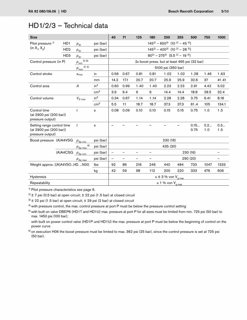
HD1/2/3 – Technical dataSize 40 71 125 180 250 355 500 750 1000
Pilot pressure 1) (in X1, X2)
HD1 pSt psi (bar) 1452) – 6503) (10 2) – 45 3))
HD2 pSt psi (bar) 1452) – 4003) (10 2) – 28 3))
HD3 pSt psi (bar) 802) – 2753) (5.5 2) – 19 3))
Control pressure (in P) pmin 5) 6) 2x boost press. but at least 465 psi (32 bar)
pmax 4) 5) 5100 psi (350 bar)
Control stroke smax in 0.56 0.67 0.81 0.81 1.02 1.02 1.28 1.46 1.63
mm 14.2 17.1 20.7 20.7 25.9 25.9 32.6 37 41.41
Control area A in2 0.60 0.99 1.40 1.40 2.23 2.23 2.91 4.42 5.02
cm2 3.9 6.4 9 9 14.4 14.4 18.8 28.5 32.4
Control volume VS max in3 0.34 0.67 1.14 1.14 2.28 2.28 3.75 6.41 8.18
cm3 5.5 11 18.7 18.7 37.3 37.3 61.4 105 134.1
Control time (at 2900 psi (200 bar)) pressure output)
t s 0.08 0.09 0.10 0.10 0.15 0.15 0.75 1.0 1.5
Setting range control time (at 2900 psi (200 bar)) pressure output)
t s – – – – – – 0.15...0.75
0.2...1.0
0.3...1.5
Boost pressure (A)A4VSG pSp min psi (bar) 230 (16)
pSp max 6) psi (bar) 435 (30)
(A)A4CSG pSp min psi (bar) – – – – 230 (16) –
pSp max psi (bar) – – – – 290 (20) –
Weight approx. ((A)A4VSO...HD. ...N00) lbs 92 86 216 246 440 484 733 1047 1333
kg 42 59 98 112 200 220 333 476 606
Hysteresis ≤ ± 3 % von Vg max
Repeatability ≤ 1 % von Vg max
1) Pilot pressure characteristics see page 6.2) ± 7 psi (0.5 bar) at open circuit; ± 22 psi (1.5 bar) at closed circuit3) ± 22 psi (1.5 bar) at open circuit; ± 29 psi (2 bar) at closed circuit4) with pressure control, the max. control pressure at port P must be below the pressure control setting5) with built on valve DBEP6 (HD1T and HD1U) max. pressure at port P for all sizes must be limited from min. 725 psi (50 bar) to
max. 1450 psi (100 bar);
with built on power control valve (HD1P und HD1U) the max. pressure at port P must be below the beginning of control on the power curve
6) on execution H06 the boost pressure must be limited to max. 362 psi (25 bar), since the control pressure is set at 725 psi (50 bar).

6/56 Bosch Rexroth Corporation HD | RA 92 080/06.06
Characteristics(A)A4VSO - open circuitPlease note: on the (A)A4VSO for open circuit (swivel to one side of center only) the Vg min-stop is set so that pump pressure reaches 20 bar when port B is closed.
Mooring or over center operation available on request.
��������
��������
��������
��������
��� ��� ��� ��� ��� � ��� ��� ��� ��� ���
��������
��������
��
�����
��
�����
�
��������
����������
��������
��������
��� ��� ��� ��� ��� � ��� ��� ��� ��� ���
��
�����
��
�����
�
��������
��������
��������
��������
(A)A4VSG and (A)A4CSG - closed circuitOn the standard execution of the (A)A4CSG (boostpump „F“) with HD, control fluid is taken internally out of the boost circuit. This eliminates the need for a separate control pressure pump.
Relation between
Direction of rotation – Pilot pressure – Direction of flow
Direction of rotation
Pilot pressure
Swivel range1)
Direction of flow
Pressure outlet port
clockwise in X1 right B to A A
in X2 left A to B B
counter clockwise
in X1 right A to B B
in X2 left B to A A
1) compare swivel angle indicator
Relation between
Direction of rotation – Pilot pressure – Direction of flow
Direction of rotation
Pilot pressure
Swivel range1)
Direction of flow
Pressure output port
clockwise in X2 left S to B B
counter clockwise
in X1 right S to B B
1) compare swivel angle indicator
Characteristic
Example: HD1 pilot pressure 10...45 bar
Characteristic
HD2 pilot pressure 145...400 psi (10...28 bar)
Characteristic
HD3 pilot pressure 80...275 psi (5.5...19 bar)
15°
0° 1
5°
Pilot pressure in X1 psi [bar]
Pilot pressure in X2 psi [bar]
Pilot pressure in X1 psi [bar]
Pilot pressure in X2 psi [bar]
15°
0° 1
5°
��
�����
��
�����
�� ��� ��� ��� ��� ������������������
����������������
����������������
��������
��������
��������
��������
��������
��������
Pilot pressure in X1 psi [bar]
Pilot pressure in X2 psi [bar]
Characteristic
HD1 pilot pressure 145...650 psi (10...45 bar)
Pilo
t pre
ssur
e in
X1/
2 ps
i [ba
r]
Displacement
��������
��������
�
��������
��������
��������
� ��� ��� ��� ��� ���
��
�����
rightleft
rightleft

RA 92 080/06.06 | HD Bosch Rexroth Corporation 7/56
P
U R(L)TK1 K2MSS
BB1 MB
X1
1.1
2P
U R(L)TK1 K2MSS
BB1 MB
X2
1.1
2
Size 40 and 71Direction of rotation clockwise Direction of rotation counter clockwise
X1X2
U M
MBB1 B
MSS R(L)TK1 K2 P
1.1
2X1X2
U M
MBB1 B
MSS R(L)TK1K2 P
1.1
2
Size 125...355Direction of rotation clockwise Direction of rotation counter clockwise
X1X2
U
B1 B MB
S MS R(L)TK2K1
M1 PM2
1.1
3
2X1X2
U
B1 B MB
S MS R(L)TK2K1
M1 PM2
1.1
3
2
Schematics (A)A4VSO HD1/2/3
Size 500...1000Direction of rotation clockwise Direction of rotation counter clockwise
PortsX1; X2 Pilot pressure ports
P Control pressure port
M; M1; M2 Gauging ports control chamber pressure
Sub-assemblies see page 8.

8/56 Bosch Rexroth Corporation HD | RA 92 080/06.06
M2M1
S MS
X1X2
K4
MK4
B AMB MAK1
R(L)TK3K2
ME3
MAB U
E3
1.3
3
2
R(L)TU K2 K3
MAMB
AB P X1X2
1.2
2
E
Size 40 and 71Example: AA4VSG
PU MR(L)TK2 K3
X2 X1
ABMAMB
E
1.2
2
Size 125...355Example: AA4VSG
Schematics (A)A4VSG and (A)A4CSG HD1/2/3Size 500...1000Example: A4CSG
Sub-assemblies1 Pump with hydraulic control device1.1 (A)A4VSO (see RA 92050)1.2 (A)A4VSG (see RA 92100)1.3 (A)A4CSG (see RA 92105)
2 Pilot control unit
3 Sandwich plate
PortsX1; X2 Pilot pressure ports
P Control pressure port (at (A)A4VSG)
M Gauging port control chamber pressure (Size 125...355)
M1 Gauging port small control chamber (Size 500...1000)
M2 Gauging port large control chamber (Size 500...1000)

RA 92 080/06.06 | HD Bosch Rexroth Corporation 9/56
15°
15°
0LR
Einschraubloch M33
X2
(X1)
R(L)
(X1), X2
B
P
A5
A4
A6
A3
(A5)
A7
A2
A1
1.1 2
P
15°
15°
0LR
Einschraubloch M33
P
B
A
X2
X1
R(L)
X1
1.2 2
P
X2
A5
A4
A6
A3
A8
A7
A9
A2
A1
Unit dimensions HD1/2/3Size 40 and 71AA4VSO – open circuit AA4VSG – closed circuit
Sub-assemblies see page 8. Ports max. tightening torques 1)
X1; X2 Pilot pressure ports ISO 11926 9/16-18UNF-2B; 0.51 (13) deep 59 lb-ft (80 Nm)AA4VSO in clockwise rotation shows only X2, AA4VSO in counter clockwise rotation has only X1
P Control pressure port Tube dia 8x1.5mm (DIN 3853 S8 Form W) 37 lb-ft (50 Nm)
Unit dimensions Size A1 A2 A3 A4 A5 A6 A7 A8 A9
4011.65(296)
7.60(193)
9.25(235)
2.28(58)
5.31(135)
8.66(220)
4.17(106)
3.25(82.5)
6.10(155)
For detailed unit dimensions and technical data on the variable pumps see the technical data sheets AA4VSO RA 92050 or AA4VSG RA 9210071
13.07(332)
8.23(209)
10.31(262)
2.28(58)
5.31(135)
9.72(247)
4.80(122)
3.25(82.5)
6.73(171)
1) see general notes
Before finalising your design please request a certified installation drawing.Dimensions in inches and (millimeters)
to pump mounting faceto pump mounting face to pump mounting face
to pump mounting face
only at counter clockwise rotation

10/56 Bosch Rexroth Corporation HD | RA 92 080/06.06
15°
15°
0LR
Einschraubloch M33
P
B
21.11.2
X1
X2
M
P
R(L)
X1, X2
A8A
2
A7
A4 A6
A3
A5
A1
Unit dimensions HD1/2/3Size 125...355AA4VSO and AA4VSG AA4CSG in preparation, dimensions on request
Ports max. tightening torques 1)
X1; X2 Pilot pressure ports ISO 11926 9/16-18UNF-2B; 0.51 (13) deep 59 lb-ft (80 Nm)on AA4VSO in clockwise rotation X1 is plugged, on AA4VSO in counter clockwise rotation X2 is plugged (M14x1.5)
P Control pressure port Tube dia 8x1,5 mm (DIN 3853 S8 Form W) (size 125 u. 180)Tube dia 12x2 mm (DIN 3853 S12 Form W) (size 250 u. 355)
37 lb-ft (50 Nm)66 lb-ft (90 Nm)
M Gauging port control chamber pressure
DIN 3852 M14x1.5; 0.47 (12) deep; plugged (size 125 a. 180)M18x1.5; 0.47 (12) deep; plugged (size 250 a. 355)
59 lb-ft (80 Nm)103 lb-ft (140 Nm)
Unit dimensionsSize A1 A2 A3 A4 A5 A6 A7 A8
125 15.83(402)
9.65(245)
9.96(253)
2.64(67)
11.61(295)
2.80(71)
4.37(111)
8.82(224)
For detailed dimensions and technical data on the variable pumps see the technical data sheetsAA4VSO RA 92050, AA4VSG RA 92100 or AA4CSG RA 92105
180 15.83(402)
9.65(245)
9.96(253)
2.64(67)
11.61(295)
2.80(71)
4.37(111)
8.82(224)
250 19.09(485)
11.71(297.5)
12.32(313)
2.80(71)
14.06(357)
2.80(71)
4.37(111)
10.24(260)
355 19.09(485)
11.71(297.5)
12.32(313)
2.80(71)
14.06(357)
2.80(71)
4.37(111)
10.24(260)
1) see general notes
Before finalising your design please request a certified installation drawing.Dimensions in inches and (millimeters)
to pump mounting face
to pump mounting face
Sub-assemblies1 Pump with hydraulic control device1.1 AA4VSO (see RA 92050)1.2 AA4VSG (see RA 92100)
2 Pilot control unit

RA 92 080/06.06 | HD Bosch Rexroth Corporation 11/56
R(L)
M2
M1
X1
P
X2
B
21.11.2
3
X1, X2
3
P
LR
A4
A7
A3A
6
A9
A8
A5
A2
A1
15°
15°
0 Einschraubloch M33
Unit dimensions HD1/2/3Size 500...1000A4VSO and A4VSG
Ports max. tightening torques 1)
X1; X2 Pilot pressure ports DIN 3852 M14x1.5; 0.47 (12) deep 59 lb-ft (80 Nm)on A4VSO in clockwise rotation X1 is plugged, on A4VSO in counter clockwise rotation X2 is plugged
P Control pressure port DIN 3852 M22x1.5; 0.55 (14) deep 155 lb-ft (210 Nm)
M1 Gauging port small control chamber DIN 3852 M18x1.5; 0.47 (12) deep; plugged 103 lb-ft (140 Nm)
M2 Gauging port large control chamber DIN 3852 M14x1.5; 0.47 (12) deep; plugged 59 lb-ft (80 Nm)
Unit dimensions
Size A1 A2 A3 A4 A5 A6 A7 A8 A9
500 21.85(555)
11.14(283)
15.08(383)
6.89(175)
7.87(200)
6.22(158)
5.71(145)
8.86(225)
19.37(492)
For detailed dimensions and technical data on the variable pumps see the technical data sheetsA4VSO RA 92050 or A4VSG RA 92100
750 24.80(630)
12.68(322)
16.34(415)
6.89(175)
9.06(230)
6.22(158)
5.71(145)
11.02(280)
20.63(524)
1000 26.38(670)
13.66(347)
18.98(482)
6.89(175)
9.96(253)
6.22(158)
5.71(145)
10.94(278)
23.23(590)
1) see general notes
to pump mounting face
to pump mounting face
Before finalising your design please request a certified installation drawing.Dimensions in inches and (millimeters)
Sub-assemblies1 Pump with hydraulic control device1.1 A4VSO (see RA 92050)1.2 A4VSG (see RA 92100)
2 Pilot control unit
3 Sandwich plate

12/56 Bosch Rexroth Corporation HD | RA 92 080/06.06
15°
15°
0LR
Einschraubloch M33
A7
A6
A 9A
8
A10
A1
21.3 3
R(L)
M2
X1
M1 X2
B
X1, X2
Unit dimensions HD1/2/3Size 500...1000A4CSG
Ports max. tightening torques 1)
X1; X2 Pilot pressure ports DIN 3852 M14x1.5; 0.47 (12) deep 59 lb-ft (80 Nm)
M1 Gauging port small control chamber DIN 3852 M22x1.5; 0.55 (14) deep; plugged 155 lb-ft (210 Nm)
M2 Gauging port large control chamber DIN 3852 M14x1.5; 0.47 (12) deep; plugged 59 lb-ft (80 Nm)
Unit dimensions
Size A1 A6 A7 A8 A9 A10
500 21.85(555)
6.22(158)
5.71(145)
8.86(225)
19.37(492)
11.69(297)
For detailed dimensions and technical data on the variable pump see the technical data sheet A4CSG RA 92105
750 24.80(630)
6.22(158)
5.71(145)
11.02(280)
20.63(524)
13.98(355)
1000 26.38(670)
6.22(158)
5.71(145)
10.94(278)
23.23(590)
–
1) see general notes
to pump mounting face
Before finalising your design please request a certified installation drawing.Dimensions in inches and (millimeters)
Sub-assemblies1 Pump with hydraulic control device1.3 A4CSG (see RA 92105)
2 Pilot control unit
3 Sandwich plate

RA 92 080/06.06 | HD Bosch Rexroth Corporation 13/56
Pressure control The pressure control is an additional function, which controls pump displacement as soon as a certain preset pressure level is rea-ched. When this preset pressure level is exceeded, the pressure control valve opens and destrokes the pump till this set pressure level is reached again. With control on both sides of center, this pressure control feature enables swiveling over center (pump „swallows“ fluid) an thereby a fast decompression of the pressure line.
On rotary drives with inert, large rotating masses, the pressure control enables a smooth, controlled deceleration.
The pressure control is optionally available as: HD.A one side in port A (schematics see page 14 and 15) HD.B one side in port B (schematics see page 22 and 23) HD.D both sides in ports A and B (schematics see page 30 and 31)
Setting range 725...5075 psi (50...350 bar)
Standard setting 5075 psi (350 bar). Other settings please state in clear text when ordering.
The settings must be 435 psi (30 bar) below the setting of the main line relief valves ((A)A4CSG), since the system induced pres-sure spikes should be limited through these relief valves.
Moreover, the setting must be higher than the control pressure level at port P.
Characteristic
Vg
Vgmax
Main line relief valves (max. 5500* psi (380* bar))Opening pressure of main line relief valves
Pressure controlSetting directly at pilot control valve (HD.A, HD.B, HD.D)or at remote pilot relief valves (HD.GA, HD.GB, HD.G) (see note referring to setting)
435
psi
(30
bar)
Displacement
Ope
ratin
g pr
essu
re p
A,B
Remote pressure control Remote control is carried out via ports XA or XB.
The external pilot pressure relief valves are not included in the supply.
Recommended: DBD 6 (RA 25 402)
The max. line lenght should not exceed 6.5 ft (2m).
The standard setting of the differential pressure at the pumps control valve is 435 psi (30 bar). With this setting the pilot oil con-sumption amounts to approx. 0.53 gpm (2 L/min). If another setting is required (range 200...725 psi (14...50 bar)) please state in clear text.Notes about the setting of the remote pressure control level:
The setting of the external relief valve plus the differential pressure at the control valve make up the value of the overall pressure control level.Example: external pilot relief valve setting 4640 psi (320 bar)
differential pressure at control valve 435 psi (30 bar)
equals pressure control level of 4640 + 435 = 5075 psi (320 + 30 = 350 bar)
Remote pressure control available as : HD.GA one side in port A (schematics see page 16 and 17) HD.GB one side in port B (schematics see page 24 and 25) HD.G both sides in ports A and B (schematics see page 32 and 33)
Pressure rise Δp ≤ 73 psi (5 bar)
Hysteresis ≤ ± 73 psi (5 bar)
* only valid in combination with pressure control – without pressure control, max. main line relief settings 5075 psi (350 bar)

14/56 Bosch Rexroth Corporation HD | RA 92 080/06.06
HD.A with pressure control on one side for port AThe pressure control valve controls the pressure in port A. Description see page 13.
Not available on AA4VSO.
Not possible for bi-directional rotation.
Schematics example AA4VSGSize 40 and 71Direction of rotation clockwise Direction of rotation counter clockwise
R(L)TU K2 K3
X1X2P
MA
ABMB
E
1.2
2
4
R(L)TU MP K2 K3
X1X2
MA
ABMB
E
1.2
2
4
Size 125...355Direction of rotation clockwise Direction of rotation counter clockwise
R(L)TU MP K2 K3
X1X2
MA
ABMB
E
1.2
2
4
PortsX1; X2 Pilot pressure ports
P Control pressure port
M Gauging port control chamber pressure (Size 125...355)
R(L)TU K2 K3
X1X2P
MA
ABMB
E
1.2
2
4
Size 500...1000 see page 15
Sub-assemblies1 Pump with hydraulic control device1.2 AA4VSG (see RA 92100)
2 Pilot control unit
4 Pressure control valve for port A

RA 92 080/06.06 | HD Bosch Rexroth Corporation 15/56
HD.A with pressure control on one side for port A
Schematics example A4VSGSize 500...1000Direction of rotation clockwise Direction of rotation counter clockwise
R(L)TU K2 K3
X1X2
MA
ABMB
M2M1
E P
1.2
4
3
2
R(L)TU K2 K3
X1X2
MA
ABMB
M2M1
E P
1.2
4
3
2
Sub-assemblies1 Pump with hydraulic control device1.2 A4VSG (see RA 92100)
2 Pilot control unit
3 Sandwich plate
4 Pressure control valve for port A
PortsX1; X2 Pilot pressure ports
P Control pressure port
M1 Gauging port small control chamber
M2 Gauging port large control chamber
Size 40...355 see page 14

16/56 Bosch Rexroth Corporation HD | RA 92 080/06.06
R(L)TU K2 K3
X1X2P
AB
1.2
2
4
XA
5
MAMB
R(L)TU MP K2 K3
X1X2
AB
1.2
2
4
XA
5
Size 125...355Direction of rotation clockwise Direction of rotation counter clockwise
R(L)TU MP K2 K3
X1X2
AB
1.2
2
4
XA
5
Sub-assemblies1 Pump with hydraulic control device1.2 AA4VSG (see RA 92100)
2 Pilot control valve
4 Pressure control valve for port A
5 External pilot relief valve (not included in supply)
PortsXA Pilot pressure port for remote pressure control in A
X1; X2 Pilot pressure ports
P Control pressure port
M Gauging port control chamber press. (Size 125...355)
R(L)TU K2 K3
X1X2P
AB
1.2
2
4
XA
5
MAMB
Size 500...1000 see page 17
HD.GA with remote pressure control for port AThe remote control is carried out via port XA. The external pilot relief valve (item 5) is not included in the supply. Description on page 13.
Not available on AA4VSO.
Not possible for bi-directional rotation.
Schematics example AA4VSGSize 40 and 71Direction of rotation clockwise Direction of rotation counter clockwise

RA 92 080/06.06 | HD Bosch Rexroth Corporation 17/56
HD.GA with remote pressure control on one side for port A
Schematics example A4VSGSize 500...1000Direction of rotation clockwise Direction of rotation counter clockwise
R(L)TU K2 K3
X1X2
MA
ABMB
M2M1
E P
1.2
2 4
3
XA
5
Sub-assemblies1 Pump with hydraulic control device1.2 A4VSG (see RA 92100)
2 Pilot control unit
3 Sandwich plate
4 Pressure control valve for port A
5 External pilot relief valve (not included in supply)
PortsXA Pilot pressure port for remote pressure control in A
X1; X2 Pilot pressure ports
P Control pressure port
M1 Gauging port small control chamber
M2 Gauging port large control chamber
R(L)TU K2 K3
X1X2
MA
ABMB
M2M1
E P
1.2
4
3
XA
52
Size 40...355 see page 16
18/56 Bosch Rexroth Corporation HD | RA 92 080/06.06
15°
15°
0LR
Einschraubloch M33
P
B
A
X2
X1
R(L)
X11.2 2
P
X2
XA4
XA
A5
A4
A6
A3
A122)
A8
A7
A10 A
13A
14
A2
A11
A153)
A9
A1
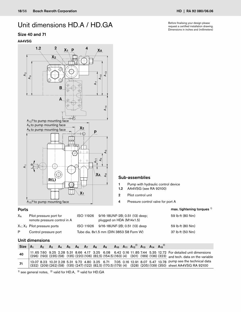
Unit dimensions HD.A / HD.GASize 40 and 71
AA4VSG
Ports max. tightening torques 1)
XA Pilot pressure port forremote pressure control in A
ISO 11926 9/16-18UNF-2B; 0.51 (13) deep; plugged on HDA (M14x1.5)
59 lb-ft (80 Nm)
X1; X2 Pilot pressure ports ISO 11926 9/16-18UNF-2B; 0.51 (13) deep 59 lb-ft (80 Nm)
P Control pressure port Tube dia. 8x1.5 mm (DIN 3853 S8 Form W) 37 lb-ft (50 Nm)
Unit dimensionsSize A1 A2 A3 A4 A5 A6 A7 A8 A9 A10 A11 A12
2) A13 A14 A153)
40 11.65(296)
7.60(193)
9.25(235)
2.28(58)
5.31(135)
8.66(220)
4.17(106)
3.25(82,5)
6.08(154.5)
6.42(163)
0.16(4)
11.85(301)
7.44(189)
5.35(136)
12.72(323)
For detailed unit dimensions and tech. data on the variable pump see the technical data sheet AA4VSG RA 92100 71 13.07
(332)8.23(209)
10.31(262)
2.28(58)
5.31(135)
9.72(247)
4.80(122)
3.25(82,5)
6.71(170.5)
7.05(179)
0.16(4)
12.91(328)
8.07(205)
5.47(139)
13.78(350)
1) see general notes, 2) valid for HD.A, 3) valid for HD.GA
to pump mounting faceto pump mounting face
Sub-assemblies1 Pump with hydraulic control device1.2 AA4VSG (see RA 92100)
2 Pilot control unit
4 Pressure control valve for port A
to pump mounting face
Before finalising your design please request a certified installation drawing.Dimensions in inches and (millimeters)
to pump mounting face

RA 92 080/06.06 | HD Bosch Rexroth Corporation 19/56
15°
15°
0LR
Einschraubloch M33
B
P 2
1.2
X1
X2
M
P
R(L)
XA
4
XAX1, X2
A8
A11
2)A2
A7
A12
A9
A4 A6
A 10
A1
A3
A5
A13A
143)
Unit dimensions HD.A / HD.GASize 125...355AA4VSG AA4CSG in preparation, dimensions on request
Ports max. tightening torques 1)
XA Pilot pressure port forremote pressure control in A
ISO 11926 9/16-18UNF-2B; 0.51 (13) deep;plugged on HDA (M14x1.5)
59 lb-ft (80 Nm)
X1; X2 Pilot pressure ports ISO 11926 9/16-18UNF-2B; 0.51 (13) deep 59 lb-ft (80 Nm)
P Control pressure port Tube dia. 8x1.5mm (DIN 3853 S8 Form W) (Size 125 a. 180)Tube dia. 12x2mm (DIN 3853 S12 Form W (Size 250 a. 355)
37 lb-ft (50 Nm)66 lb-ft (90 Nm)
M Gauging port control chamber pressure
DIN 3852 M14x1.5; 0.47 (12) deep; plugged (Size 125 a. 180)M18x1.5; 0.47 (12) deep; plugged (Size 250 a. 355)
59 lb-ft (80 Nm)103 lb-ft (140 Nm)
Unit dimensionsSize A1 A2 A3 A4 A5 A6 A7 A8 A9 A10 A11
2) A12 A13 A143)
125 15.83(402)
9.65(245)
9.96(253)
2.64(67)
11.61(295)
2.80(71)
4.37(111)
8.82(224)
0.51(13)
14.49(368)
7.56(192)
8.82(224)
15.51(394)
8.43(214) For detailed dimensions
and technical data on the variable pumps see the technical data sheets AA4VSG RA 92100 or AA4CSG RA 92105
180 15.83(402)
9.65(245)
9.96(253)
2.64(67)
11.61(295)
2.80(71)
4.37(111)
8.82(224)
0.51(13)
14.49(368)
7.56(192)
8.82(224)
15.59(396)
8.43(214)
250 19.09(485)
11.71(297,5)
12.32(313)
2.80(71)
14.06(357)
2.80(71)
4.37(111)
10.24(260)
0.51(13)
16.93(430)
8.98(228)
8.82(224)
17.95(456)
9.84(250)
355 19.09(485)
11.71(297,5)
12.32(313)
2.80(71)
14.06(357)
2.80(71)
4.37(111)
10.24(260)
0.51(13)
16.93(430)
8.98(228)
8.82(224)
17.95(456)
9.84(250)
1) see general notes, 2) valid for HD.A, 3) valid for HD.GA
to pump mounting face
Sub-assemblies1 Pump with hydraulic control device1.2 AA4VSG (see RA 92100)
2 Pilot control unit
4 Pressure control valve for port A
to pump mounting faceto pump mounting face
to pump mounting face
Before finalising your design please request a certified installation drawing.Dimensions in inches and (millimeters)

20/56 Bosch Rexroth Corporation HD | RA 92 080/06.06
Before finalising your design please request a certified installation drawing.Dimensions in inches and (millimeters)
R(L)
M2
M1
X1
PX2
B
2
1.2
3
X1, X2
3
PXA
XA
4
A4
A11 A
7
A 3
A13
A8
A12
A5
A2
A1
A 9
15°
15°
0LR
Einschraubloch M33
A6
to pump mounting faceto pump mounting face
Unit dimensions HD.A / HD.GASize 500...1000A4VSG
Ports max. tightening torques 1)
XA Pilot pressure port forremote pressure control in A DIN 3852 M14x1.5; 0.47 (12) deep; plugged on HDA 59 lb-ft (80 Nm)
X1; X2 Pilot pressure ports DIN 3852 M14x1.5; 0.47 (12) deep 59 lb-ft (80 Nm)
P Control pressure port DIN 3852 M22x1.5; 0.55 (14) deep 155 lb-ft (210 Nm)
M1 Gauging port small control chamber DIN 3852 M18x1.5; 0.47 (12) deep; plugged 103 lb-ft (140 Nm)
M2 Gauging port large control chamber DIN 3852 M14x1.5; 0.47 (12) deep; plugged 59 lb-ft (80 Nm)
Unit dimensions
Size A1 A2 A3 A4 A5 A6 A7 A8 A9 A11 A12 A13
500 21.85(555)
13.46(342)
15.08(383)
6.89(175)
7.87(200)
6.22(158)
5.71(145)
8.86(225)
19.37(492)
5.35(136)
12.40(315)
18.46(469) For detailed dimensions and
technical data on the variable pump see the technical data sheet A4VSG RA 92100
750 24.80(630)
14.61(371)
16.34(415)
6.89(175)
9.06(230)
6.22(158)
5.71(145)
11.02(280)
20.63(524)
5.35(136)
13.58(345)
19.72(501)
1000 26.38(670)
15.51(394)
18.94(481)
6.89(175)
9.96(253)
6.22(158)
5.71(145)
10.94(278)
23.23(590)
5.35(136)
14.49(368)
22.32(567)
1) see general notes
to pump mounting face
Sub-assemblies1 Pump with hydraulic control device1.2 A4VSG (see RA 92100)
2 Pilot control unit
3 Sandwich plate
4 Pressure control valve for port A

RA 92 080/06.06 | HD Bosch Rexroth Corporation 21/56
Before finalising your design please request a certified installation drawing.Dimensions in inches and (millimeters)
Unit dimensions HD.A / HD.GASize 500...1000A4CSG
X1
M1
B
1.3X1, X2
R(L)
M2
X2
23 XA4
XA
L
A7
A11
A6
A 9
A13A
12
A8
A2
A1
15°
15°
0
R
Einschraubloch M33
to pump mounting faceto pump mounting face
Ports max. tightening torques 1)
XA Pilot pressure port forremote pressure control in A DIN 3852 M14x1.5; 0.47 (12) deep; plugged on HDA 59 lb-ft (80 Nm)
X1; X2
Pilot pressure ports DIN 3852 M14x1.5; 0.47 (12) deep 59 lb-ft (80 Nm)
M1 Gauging port small control chamber DIN 3852 M22x1.5; 0.55 (14) deep; plugged (A4CSG) 155 lb-ft (210 Nm)
M2 Gauging port large control chamber DIN 3852 M14x1.5; 0.47 (12) deep; plugged 59 lb-ft (80 Nm)
Unit dimensions
Size A1 A2 A6 A7 A8 A9 A11 A12 A13
500 21.85(555)
13.46(342)
6.22(158)
5.71(145)
8.86(225)
19.37(492)
5.35(136)
12.40(315)
18.46(469)
For detailed dimensions and technical data on the variable pump see the technical data sheet A4CSG RA 92105
750 24.80(630)
14.61(371)
6.22(158)
5.71(145)
11.02(280)
20.63(524)
5.35(136)
13.58(345)
19.72(501)
1000 26.38(670)
15.51(394)
6.22(158)
5.71(145)
10.94(278)
23.23(590)
5.35(136)
14.49(368)
22.32(567)
1) see general notes
Sub-assemblies1 Pump with hydraulic control device1.3 A4CSG (see RA 92105)
2 Pilot control unit
3 Sandwich plate
4 Pressure control valve for port A

22/56 Bosch Rexroth Corporation HD | RA 92 080/06.06
HD.B with pressure control on one side for port BThe pressure control valve controls the pressure in port B. Description see page 13.
Not possible for bi-directional rotation.
Schematics Size 40 and 71Direction of rotation clockwise Direction of rotation counter clockwise(Example AA4VSO) (Example AA4VSO)
X2P
MBB
1.1
2
4
B1
R(L)TU S MS K2 K3
R(L)TU MK2MSS K3
X1
P
B
1.1
2
4
X2
MBB1
Size 125...355Direction of rotation clockwise Direction of rotation counter clockwise(Example AA4VSO) (Example AA4VSG)
R(L)TU MK2 K3
X1
P
AB
1.2
2
4
X2
R(L)TU S MS K2 K3
X1P
MBB
1.1
2
4
B1
PortsX1; X2 Pilot pressure ports
P Control pressure port
M Gauging port control chamber pressure (Size 125...355)
Size 500...1000 see page 23
Sub-assemblies1 Pump with hydraulic control device1.1 AA4VSO (see RA 92050)1.2 AA4VSG (see RA 92100)
2 Pilot control unit
4 Pressure control valve for port B

RA 92 080/06.06 | HD Bosch Rexroth Corporation 23/56
HD.B with pressure control on one side for port B
Schematics example A4VSOSize 500...1000Direction of rotation clockwise Direction of rotation counter clockwise
R(L)TU K2MSS K3
X1
PB
1.1
2 4X2
MBB1
M2M1
3
R(L)TU K2MSS K3
X1
PB
1.1
2 4X2
MBB1
M2M1
3
Sub-assemblies1 Pump with hydraulic control device1.1 A4VSO (see RA 92050)
2 Pilot control unit
3 Sandwich plate
4 Pressure control valve for port B
PortsX1; X2 Pilot pressure ports
P Control pressure port
M1 Gauging port small control chamber
M2 Gauging port large control chamber
Size 40...355 see page 22

24/56 Bosch Rexroth Corporation HD | RA 92 080/06.06
HD.GB with remote pressure control for port BThe remote pressure control is carried out via port XB. The external pilot relief valve (item 5) is not included in the supply. Description see page 13.
Not possible for bi-directional rotation.
Schematics example AA4VSGSize 40 and 71Direction of rotation clockwise Direction of rotation counter clockwise
R(L)TU K2 K3
X1X2P
AB
1.2
2
4
XB
5
MAMB
R(L)TU K2 K3
X1X2
P
AB
1.2
2
4
XB
5
M
Size 125...355Direction of rotation clockwise Direction of rotation counter clockwise
R(L)TU K2 K3
X1X2
P
AB
1.2
2
4
XB
5
M
PortsXB Pilot pressure port for remote pressure control in B
X1; X2 Pilot pressure ports
P Control pressure port
M Gauging port control chamber pressure (Size 125...355)
Size 500...1000 see page 25
R(L)TU K2 K3
X1X2P
AB
1.2
2
4
XB
5
MAMB
Sub-assemblies1 Pump with hydraulic control device1.2 AA4VSG (see RA 92100)
2 Pilot control unit
4 Pressure control valve for port B
5 External pilot relief valve (not included in supply)

RA 92 080/06.06 | HD Bosch Rexroth Corporation 25/56
HD.GB with remote pressure control for port B
Schematics example A4VSOSize 500...1000Direction of rotation clockwise Direction of rotation counter clockwise
R(L)TU K2MSS K3
X1
PB
1.1
2
4
X2
MBB1
M2M1
3
XB
5
R(L)TU K2MSS K3
X1
PB
1.1
2
4
X2
MBB1
M2M1
3
XB
5
Sub-assemblies1 Pump with hydraulic control device1.1 A4VSO (see RA 92050)
2 Pilot control valve
3 Sandwich plate
4 Pressure control valve for port B
5 External pilot relief valve (not included in supply)
PortsXB Pilot pressure port for remote pressure control in B
X1; X2 Pilot pressure ports
P Control pressure port
M1 Gauging port small control chamber
M2 Gauging port large control chamber
Size 40...355 see page 24

26/56 Bosch Rexroth Corporation HD | RA 92 080/06.06
15°
15°
0LR
Einschraubloch M33
P
X2
R(L)
1.1 2
P
(X1), X2
XB4
XB
B
(X1)
A5
A4
A6
A3
A12
A7
A10 A
13
A2
A1
A11
(A5)
A15
Unit dimensions HD.B / HD.GBSize 40 and 71
AA4VSO AA4VSG
2) to pump mounting faceto pump mounting faceto pump mounting face
Sub-assemblies see page 27
Ports max. tightening torques 1)
XB Pilot pressure port forremote pressure control in B
ISO 11926 9/16-18UNF-2B; 0.51 (13) deep; plugged on HDB (M14x1.5)
59 lb-ft (80 Nm)
X1; X2 Pilot pressure ports ISO 11926 9/16-18UNF-2B; 0.51 (13) deep 59 lb-ft (80 Nm)on AA4VSO clockwise rotation only X2 exists, on AA4VSO counter clockwise rotation only X1 exists
P Control pressure port Tube dia. 8x1.5 mm (DIN 3853 S8 Form W) 37 lb-ft (50 Nm)
Unit dimensionsSize A1 A2 A3 A4 A5 A6 A7 A8 A9 A10 A11 A12
2) A13 A14 A153)
4011.65(296)
7.60(193)
9.25(235)
2.28(58)
5.31(135)
8.66(220)
4.17(106)
3.25(82.5)
6.08(154.5)
6.42(163)
0.16(4)
11.85(301)
7.44(189)
5.35(136)
12.72(323)
For detailed unit dimensions and tech. data on the variable pumps see the technical data sheets AA4VSO RA 92050 or AA4VSG RA 92100
7113.07(332)
8.23(209)
10.31(262)
2.28(58)
5.31(135)
9.72(247)
480(122)
3.25(82.5)
6.71(170.5)
7.05(179)
0.16(4)
12.91(328)
8.07(205)
5.47(139)
13.78(350)
1) see general notes, 2) valid for HD.B, 3) valid for HD.GB
15°
15°
0LR
Einschraubloch M33
P
B
A
X2
X1
R(L)
X11.2 2
P
X2
XB4
XB
A5
A4
A6
A3
A12
A8
A7
A9 A10 A
13A
14
A2
A1
A11
A15
2) to pump mounting faceto pump mounting faceto pump mounting face
only on counterclockwise rotation
Before finalising your design please request a certified installation drawing.Dimensions in inches and (millimeters)
3) to pump mounting face
3) to pump mounting face

RA 92 080/06.06 | HD Bosch Rexroth Corporation 27/56
15°
15°
0LR
Einschraubloch M33
P
B
2
1.11.2
X1
X2
M
P
R(L)
XB
4XBX1, X2
A14
4)
A11
3)
A8
A7
A12
2 )
A9
A4 A6
A 10
A1
A3
A13
A2
A5
Unit dimensions HD.B / HD.GBSize 125...355AA4VSO and AA4VSG AA4CSG in preparation, dimensions on request
Ports max. tightening torques 1)
XB Pilot pressure port forremote pressure control in B
ISO 11926 9/16-18UNF-2B; 0.51 (13) deep;plugged on HDB (M14x1.5)
59 lb-ft (80 Nm)
X1; X2 Pilot pressure ports ISO 11926 9/16-18UNF-2B; 0.51 (13) deep 59 lb-ft (80 Nm)on AA4VSO in clockwise rotation X1 is plugged, on AA4VSO in counter clockwise rotation X2 is plugged (M14x1.5)
P Control pressure port Tube dia. 8x1.5mm (DIN 3853 S8 Form W) (Size 125 a. 180)Tube dia. 12x2mm (DIN 3853 S12 Form W (Size 250 a. 355)
37 lb-ft (50 Nm)66 lb-ft (90 Nm)
M Gauging port control chamber pressure
DIN 3852 M14x1.5; 0.47 (12) deep; plugged (Size 125 a. 180)M18x1.5; 0.47 (12) deep; plugged (Size 250 a. 355)
59 lb-ft (80 Nm)103 lb-ft (140 Nm)
Unit dimensionsSize A1 A2 A3 A4 A5 A6 A7 A8 A9 A10 A11
3) A12 A13 A144)
125 15.83(402)
9.65(245)
9.96(253)
2.64(67)
11.61(295)
2.80(71)
4.37(111)
8.82(224)
0.51(13)
14.49(368)
7.56(192)
8.82(224)
15.51(394)
8.43(214) For detailed dimensions
and technical data on the variable pumps see the technical data sheets AA4VSO RA 92050, AA4VSG RA 92100 or AA4CSG RA 92105
180 15.83(402)
9.65(245)
9.96(253)
2.64(67)
11.61(295)
2.80(71)
4.37(111)
8.82(224)
0.51(13)
14.49(368)
7.56(192)
8.82(224)
15.51(394)
8.43(214)
250 19.09(485)
11.73(298)
12.32(313)
2.80(71)
14.06(357)
2.80(71)
4.37(111)
10.24(260)
0.51(13)
16.93(430)
8.98(228)
8.82(224)
17.95(456)
9.84(250)
355 19.09(485)
11.73(298)
12.32(313)
2.80(71)
14.06(357)
2.80(71)
4.37(111)
10.24(260)
0.51(13)
16.93(430)
8.98(228)
8.82(224)
17.95(456)
9.84(250)
1) see general notes, 2) Piping exists only on AA4VSO, 3) valid for HD.B, 4) valid for HD.GB
to pump mounting face
Sub-assemblies1 Pump with hydraulic control device1.1 AA4VSO (see RA 92050)1.2 AA4VSG (see RA 92100)1.3 AA4CSG (see RA 92105)
2 Pilot control unit
4 Pressure control valve for port B
to pump mounting faceto pump mounting face
to pump mounting face
Before finalising your design please request a certified installation drawing.Dimensions in inches and (millimeters)

28/56 Bosch Rexroth Corporation HD | RA 92 080/06.06
R(L)
M2
M1
X1
PX2
B
2
1.11.2
3
X1, X2
3
PXB4
XB
LR
A4
A7
A11
A3
A6
A13
A8
A12
A5
A2
A1
A 9
15°
15°
0 Einschraubloch M33
Unit dimensions HD.B / HD.GBSize 500...1000A4VSO and A4VSG
to pump mounting face
to pump mounting face
to pump mounting face
Before finalising your design please request a certified installation drawing.Dimensions in inches and (millimeters)
Ports max. tightening torques 1)
XB Pilot pressure port forremote pressure control in B DIN 3852 M14x1.5; 0.47 (12) deep; plugged on HDB 59 lb-ft (80 Nm)
X1; X2 Pilot pressure ports DIN 3852 M14x1.5; 0.47 (12) deep 59 lb-ft (80 Nm)on A4VSO in clockwise rotation X1 is plugged, on A4VSO in counter clockwise rotation X2 is plugged
P Control pressure port DIN 3852 M22x1.5; 0.55 (14) deep 155 lb-ft (210 Nm)
M1 Gauging port small control chamber DIN 3852 M18x1.5; 0.47 (12) deep; plugged 103 lb-ft (140 Nm)
M2 Gauging port large control chamber DIN 3852 M14x1.5; 0.47 (12) deep; plugged 59 lb-ft (80 Nm)
Unit dimensions
Size A1 A2 A3 A4 A5 A6 A7 A8 A9 A11 A12 A13
500 21.85(555)
13.46(342)
15.08(383)
6.89(175)
7.87(200)
6.22(158)
5.71(145)
8.86(225)
19.37(492)
5.35(136)
11.97(304)
18.46(469) For detailed dimensions and
tech. data on the variable pumps see the technical data sheets A4VSO RA 92050 or A4VSG RA 92100
750 24.80(630)
14.61(371)
16.34(415)
6.89(175)
9.06(230)
6.22(158)
5.71(145)
11.02(280)
20.63(524)
5.35(136)
13.15(334)
19.72(501)
1000 26.38(670)
15.51(394)
18.94(481)
6.89(175)
9.96(253)
6.22(158)
5.71(145)
10.94(278)
23.23(590)
5.35(136)
14.06(357)
22.32(567)
1) see general notes
Sub-assemblies1 Pump with hydraulic control device1.1 A4VSO (see RA 92050)1.2 A4VSG (see RA 92100)
2 Pilot control unit
3 Sandwich plate
4 Pressure control valve for port B

RA 92 080/06.06 | HD Bosch Rexroth Corporation 29/56
Unit dimensions HD.B / HD.GBSize 500...1000A4CSG
X1
M1
B
1.3X1, X2
R(L)
M2
X2
23 XB4
XB
LR
A7
A11
A6
A 9
A13
A12
A8
A2
A1
15°
15°
0 Einschraubloch M33
to pump mounting face
to pump mounting face
Before finalising your design please request a certified installation drawing.Dimensions in inches and (millimeters)
Ports max. tightening torques 1)
XB Pilot pressure port forremote pressure control in B DIN 3852 M14x1.5; 0.47 (12) deep; plugged on HDB 59 lb-ft (80 Nm)
X1; X2 Pilot pressure ports DIN 3852 M14x1.5; 0.47 (12) deep 59 lb-ft (80 Nm)
M1 Gauging port small control chamber DIN 3852 M22x1.5; 0.55 (14) deep; plugged 155 lb-ft (210 Nm)
M2 Gauging port large control chamber DIN 3852 M14x1.5; 0.47 (12) deep; plugged 59 lb-ft (80 Nm)
Unit dimensions
Size A1 A2 A6 A7 A8 A9 A11 A12 A13
500 21.85(555)
13.46(342)
6.22(158)
5.71(145)
8.86(225)
19.37(492)
5.35(136)
11.97(304)
18.46(469)
For detailed dimensions and technical data on the variable pump see the technical data sheet A4CSG RA 92105
750 24.80(630)
14.61(371)
6.22(158)
5.71(145)
11.02(280)
20.63(524)
5.35(136)
13.15(334)
79.72(501)
1000 26.38(670)
15.51(394)
6.22(158)
5.71(145)
10.94(278)
23.23(590)
5.35(136)
14.06(357)
22.32(567)
1) see general notes
Sub-assemblies1 Pump with hydraulic control device1.3 A4CSG (see RA 92105)
2 Pilot control unit
3 Sandwich plate
4 Pressure control valve for port B

30/56 Bosch Rexroth Corporation HD | RA 92 080/06.06
HD.D with pressure control for ports A and BTwo pressure control valves enable a control of max. pressure in ports A or B independent of each other. Description see page 13.
Not available on AA4VSO.
Not possible for bi-directional rotation.
Schematics example AA4VSGSize 40 and 71Direction of rotation clockwise Direction of rotation counter clockwise
X2 X1P
AMB MAB
1.2
2 4 6
R(L)TU K2 K3
X2 X1
P
A
M
B
1.2
2 4
R(L)TU K2 K3
6
Size 125...355Direction of rotation clockwise Direction of rotation counter clockwise
X2 X1
P
A
M
B
1.2
2 4
R(L)TU K2 K3
6
Sub-assemblies1 Pump with hydraulic control device1.2 AA4VSG (see RA 92100)
2 Pilot control unit
4 Pressure control valve for port A (for port B on counter clockwise rotation)
6 Pressure control valve for port B (for port A on counter clockwise rotation)
PortsX1; X2 Pilot pressure ports
P Control pressure port
M Gauging port control chamber pressure (Size 125...355)
Size 500...1000 see page 31
X2 X1P
AMB MAB
1.2
2 4 6
R(L)TU K2 K3

RA 92 080/06.06 | HD Bosch Rexroth Corporation 31/56
HD.D with pressure control on both sides for ports A and B
Schematics example A4VSGSize 500...1000Direction of rotation clockwise Direction of rotation counter clockwise
X2 X1
AMB MA
B
1.2
2 4 6
R(L)TU K2 K3
EM1M2
P
3E
X2 X1
AMB MA
B
1.2
R(L)TU K2 K3
M1M2
P
3
2 4 6
Sub-assemblies1 Pump with hydraulic control device1.2 A4VSG (see RA 92100)
2 Pilot control valve
4 Pressure control valve for port A
6 Pressure control valve for port B
PortsX1; X2 Pilot pressure ports
P Control pressure port
M1 Gauging port small control chamber
M2 Gauging port large control chamber
Size 40...355 see page 30

32/56 Bosch Rexroth Corporation HD | RA 92 080/06.06
HD.G with remote pressure control for A and BThe remote pressure control is carried out via the ports XA and XB. The external pilot relief valves (item 5 and item 7) are not included in the supply. Description see page 13.
Not available on AA4VSO.
Not possible for bi-directional rotation.
Schematics example AA4VSGSize 40 and 71Direction of rotation clockwise Direction of rotation counter clockwise
X2 X1P
AMB MAB
1.2
2 4 6
R(L)TU K2 K3
XA XB
5 7
X2 X1
AB
1.2
2 4 6
R(L)TU K2 K3
XA XB
5 7
P M
Size 125...355Direction of rotation clockwise Direction of rotation counter clockwise
X2 X1
AB
1.2
2 4 6
R(L)TU K2 K3
XA XB
5 7
P M
Sub-assemblies1 Pump with hydraulic control device1.2 AA4VSG (see RA 92100)
2 Pilot control unit
4 Pressure control valve for port A (for port B on counter clockwise rotation)
5; 7 External pilot relief valves (not included in supply)
6 Pressure control valve for port B (for port A on counter clockwise rotation)
PortsXA; XB Pilot pressure ports for remote pressure control
X1; X2 Pilot pressure ports
P Control pressure port
M Gauging port control chamber pressure (size 125...355)
Size 500...1000 see page 33
X2 X1P
AMB MAB
1.2
2 4 6
R(L)TU K2 K3
XB XA
5 7

RA 92 080/06.06 | HD Bosch Rexroth Corporation 33/56
HD.G with remote pressure control on both side for A and B
Schematics example A4VSGSize 500...1000Direction of rotation clockwise Direction of rotation counter clockwise
X2 X1
AMB MA
B
1.2
2 4 6
R(L)TU K2 K3
EM1M2
XA XB
P
5 7
3E
X2 X1
AMB MA
B
1.2
2 4 6
R(L)TU K2 K3
M1M2
XA XB
P
5 7
3
Sub-assemblies1 Pump with hydraulic control device1.2 A4VSG (see RA 92100)
2 Pilot control unit
3 Sandwich plate
4 Pressure control valve for port A
5; 7 External pilot relief valves (not included in supply)
6 Pressure control valve for port B
PortsXA Pilot pressure port for remote pressure control in A
XB Pilot pressure port for remote pressure control in B
X1; X2 Pilot pressure ports
P Control pressure port
M1 Gauging port small control chamber
M2 Gauging port large control chamber
Size 40...355 see page 32

34/56 Bosch Rexroth Corporation HD | RA 92 080/06.06
15°
15°
0LR
Einschraubloch M33
P
B
A
X2
X1
R(L)
X1
1.2
2
P
X2
XB
XA
XB, XA
6
4
A5
A11 A
4
A6
A3
A8
A7
A9
A10
A1
A2 A13 A
14
A15
A12
A16
Unit dimensions HD.D / HD.GSize 40 and 71AA4VSG
Ports max. tightening torques 1)
XA; XB Pilot pressure ports forremote pressure control
ISO 11926 9/16-18UNF-2B; 0.51 (13) deep; plugged on HDD (M14x1.5)
59 lb-ft (80 Nm)
X1; X2 Pilot pressure ports ISO 11926 9/16-18UNF-2B; 0.51 (13) deep 59 lb-ft (80 Nm)
P Control pressure port Tube dia. 8x1.5 mm (DIN 3853 S8 Form W) 37 lb-ft (50 Nm)
Unit dimensionsSize A1 A2 A3 A4 A5 A6 A7 A8 A9 A10 A11 A12
2) A13 A14 A15 A163)
4011.65(296)
7.60(193)
9.25(235)
2.28(58)
5.31(135)
8.66(220)
4.17(106)
3.25(82.5)
6.10(155)
6.42(163)
0.16(4)
11.85(301)
7.99(203)
9.02(229)
6.50(165)
12.72(323)
For detailed unit dimen-sions and tech. data on the variable pump see the tech. data sheet AA4VSG RA 92100
7112.68(332)
8.23(209)
10.31(262)
2.28(58)
5.31(135)
9.76(248)
480(122)
3.25(82.5)
6.73(171)
7.05(179)
0.16(4)
12.91(328)
8.62(219)
9.65(245)
6.61(168)
13.78(350)
1) see general notes, 2) valid for HD.D, 3) valid for HD.G
to pump mounting faceto pump mounting face
2) to pump mounting face
Sub-assemblies1 Pump with hydraulic control device1.2 AA4VSG (see RA 92100)
2 Pilot control unit
4 Pressure control valve for port A (for port B on counter clockwise rotation size 40...355)
6 Pressure control valve for port B (for port A on counter clockwise rotation size 40...355)
Before finalising your design please request a certified installation drawing.Dimensions in inches and (millimeters)
3) to pump mounting face

RA 92 080/06.06 | HD Bosch Rexroth Corporation 35/56
15°
15°
0LR
Einschraubloch M33
XAP
B
21.2
X1 X2
M
P
R(L) XA XB
64
XBX1, X2
A11
2)
A16
3)
A8
A7
A13
A14A9
A4 A6
A 10
A12
A15
A1
A3
A5
A2
to pump mounting faceto pump mounting face
Unit dimensions HD.D / HD.GSize125...355AA4VSG
Ports max. tightening torques 1)
XA; XB Pilot pressure ports forremote pressure control
ISO 11926 9/16-18UNF-2B; 0.51 (13) deep;plugged on HDD (M14x1.5)
59 lb-ft (80 Nm)
X1; X2 Pilot pressure ports ISO 11926 9/16-18UNF-2B; 0.51 (13) deep 59 lb-ft (80 Nm)
P Control pressure port Tube dia. 8x1.5mm (DIN 3853 S8 Form W) (Size 125 a. 180)Tube dia. 12x2mm (DIN 3853 S12 Form W) (Size 250 a. 355)
37 lb-ft (50 Nm)66 lb-ft (90 Nm)
M Gauging port control chamber pressure
DIN 3852 M14x1.5; 0.47 (12) deep; plugged (Size 125 a. 180)M18x1.5; 0.47 (12) deep; plugged (Size 250 a. 355)
59 lb-ft (80 Nm)103 lb-ft (140 Nm)
Unit dimensionsSize A1 A2 A3 A4 A5 A6 A7 A8 A9 A10 A11
2) A12 A13 A14 A15 A163)
125 15.83(402)
9.65(245)
9.96(253)
2.64(67)
11.61(295)
2.80(71)
4.37(111)
8.82(224)
0.51(13)
14.49(368)
7.56(192)
16.06(408)
9.41(239)
8.82(224)
17.09(434)
8.43(214) For detailed
dimensions and tech. data on the variable pump see the tech. data sheet AA4VSG RA 92100
180 15.83(402)
9.65(245)
9.96(253)
2.64(67)
11.61(295)
2.80(71)
4.37(111)
8.82(224)
0.51(13)
14.49(368)
7.56(192)
16.06(408)
9.41(239)
8.82(224)
17.09(434)
8.43(214)
250 19.09(485)
11.73(298)
12.32(313)
2.80(71)
14.06(357)
2.80(71)
4.37(111)
10.24(260)
0.51(13)
16.93(430)
8.98(228)
18.50(470)
9.41(239)
8.82(224)
19.53(496)
9.84(250)
355 19.09(485)
11.73(298)
12.32(313)
2.80(71)
14.06(357)
2.80(71)
4.37(111)
10.24(260)
0.51(13)
16.93(430)
8.98(228)
18.50(470)
9.41(239)
8.82(224)
19.53(496)
9.84(250)
1) see general notes, 2) valid for HD.D, 3) valid for HD.G
to pump mounting face
to pump mounting faceto pump mounting face
C.c
lock
wis
e ro
tatio
nC
lock
wis
e ro
tatio
n
Before finalising your design please request a certified installation drawing.Dimensions in inches and (millimeters)
Sub-assemblies1 Pump with hydraulic control device1.2 AA4VSG (see RA 92100)
2 Pilot control unit
4 Pressure control valve for port A (for port B on counter clockwise rotation size 40...355)
6 Pressure control valve for port B (for port A on counter clockwise rotation size 40...355)

36/56 Bosch Rexroth Corporation HD | RA 92 080/06.06
Unit dimensions HD.D / HD.GSize125...355AA4CSG
Ports max. tightening torques 1)
XA; XB Pilot pressure ports forremote pressure control
ISO 11926 9/16-18UNF-2B; 0.51 (13) deep;plugged on HDD (M14x1.5)
59 lb-ft (80 Nm)
X1; X2 Pilot pressure ports ISO 11926 9/16-18UNF-2B; 0.51 (13) deep 59 lb-ft (80 Nm)
M Gauging port control chamber pressure
DIN 3852 M14x1.5; 0.47 (12) deep; plugged (Size 125 a. 180)M18x1.5; 0.47 (12) deep; plugged (Size 250 a. 355)
59 lb-ft (80 Nm)103 lb-ft (140 Nm)
Unit dimensionsSize A1 A5 A6 A7 A8 A9 A10 A11
2) A12 A15 A163)
125 15.83(402)
11.61(295)
2.80(71)
4.37(111)
8.82(224)
0.51(13)
14.49(368)
7.56(192)
16.06(408)
17.09(434)
8.43(214)
For detailed dimensions and technical data on the variable pump see the technical data sheet AA4CSG RA 92105
180 15.83(402)
11.61(295)
2.80(71)
4.37(111)
8.82(224)
0.51(13)
14.49(368)
7.56(192)
16.06(408)
17.09(434)
8.43(214)
250 19.09(485)
14.06(357)
2.80(71)
4.37(111)
10.24(260)
0.51(13)
16.93(430)
8.98(228)
18.50(470)
19.53(496)
9.84(250)
355 19.09(485)
14.06(357)
2.80(71)
4.37(111)
10.24(260)
0.51(13)
16.93(430)
8.98(228)
18.50(470)
19.53(496)
9.84(250)
1) see general notes, 2) valid for HD.D, 3) valid for HD.G
XA XB
15°
15°
0LR
Einschraubloch M33
X1 X2
B
R(L)
21.3
64
X1, X2
A7
A9
A6
A 5
A1
A11
2)
A16
3)
A8
A 10
A12
A15
XA XB
to pump mounting face
to pump mounting faceto pump mounting face
to pump mounting face
Before finalising your design please request a certified installation drawing.Dimensions in inches and (millimeters)
Sub-assemblies1 Pump with hydraulic control device1.3 AA4CSG (see RA 92105)
2 Pilot control unit
4 Pressure control valve for port A (for port B on counter clockwise rotation size 40...355)
6 Pressure control valve for port B (for port A on counter clockwise rotation size 40...355)

RA 92 080/06.06 | HD Bosch Rexroth Corporation 37/56
Sub-assemblies1 Pump with hydraulic control device1.2 A4VSG (see RA 92100)
2 Pilot control unit
3 Sandwich plate
4 Pressure control valve for port A
6 Pressure control valve for port B
R(L)
M2
M1
X1
PX2
B
2
1.2
3
X1, X2
3
PXA
4
XA
XB
6
XB
A4
A11 A
7A
11
A3
A6
A13
A8
A14 A12
A5
A2
A1
A 9
15°
15°
0LR
Einschraubloch M33
to pump mounting face
to pump mounting face
Unit dimensions HD.D / HD.GSize 500...1000A4VSG
Ports max. tightening torques 1)
XA; XB Pilot pressure ports forremote pressure control DIN 3852 M14x1.5; 0.47 (12) deep; plugged on HDB 59 lb-ft (80 Nm)
X1; X2 Pilot pressure ports DIN 3852 M14x1.5; 0.47 (12) deep 59 lb-ft (80 Nm)
P Control pressure port DIN 3852 M22x1.5; 0.55 (14) deep 155 lb-ft (210 Nm)
M1 Gauging port small control chamber DIN 3852 M18x1.5; 0.47 (12) deep; plugged 103 lb-ft (140 Nm)
M2 Gauging port large control chamber DIN 3852 M14x1.5; 0.47 (12) deep; plugged 59 lb-ft (80 Nm)
Unit dimensions
Size A1 A2 A3 A4 A5 A6 A7 A8 A9 A11 A12 A13 A14
500 21.85(555)
13.46(342)
15.08(383)
6.89(175)
7.87(200)
6.22(158)
5.71(145)
8.86(225)
19.37(492)
5.35(136)
12.40(315)
18.46(469)
11.97(304) For detailed dimensions
and tech. data on the variable pump see the technical data sheet A4VSG RA 92100
750 24.80(630)
14.61(371)
16.34(415)
6.89(175)
9.06(230)
6.22(158)
5.71(145)
11.02(280)
20.63(524)
5.35(136)
13.58(345)
19.72(501)
13.15(334)
1000 26.38(670)
15.51(394)
18.94(481)
6.89(175)
9.96(253)
6.22(158)
5.71(145)
10.94(278)
23.23(590)
5.35(136)
14.49(368)
22.32(567)
14.06(357)
1) see general notes
to pump mounting face
Before finalising your design please request a certified installation drawing.Dimensions in inches and (millimeters)

38/56 Bosch Rexroth Corporation HD | RA 92 080/06.06
Sub-assemblies1 Pump with hydraulic control device1.3 A4CSG (see RA 92105)
2 Pilot control unit
3 Sandwich plate
4 Pressure control valve for port A
6 Pressure control valve for port B
Unit dimensions HD.D / HD.GSize 500...1000A4CSG
X1
M1
B
1.3X1, X2
R(L)
M2
X2
23 XA
XA
4
6
XB
LR
A7
A11
A11
A6
A 9
A13
A12
A8
A2
A1
15°
15°
0 Einschraubloch M33
to pump mounting faceto pump mounting face
Ports max. tightening torques 1)
XA; XB Pilot pressure ports forremote pressure control DIN 3852 M14x1.5; 0.47 (12) deep; plugged on HDB 59 lb-ft (80 Nm)
X1; X2 Pilot pressure ports DIN 3852 M14x1.5; 0.47 (12) deep 59 lb-ft (80 Nm)
M1 Gauging port small control chamber DIN 3852 M22x1.5; 0.55 (14) deep; plugged 155 lb-ft (210 Nm)
M2 Gauging port large control chamber DIN 3852 M14x1.5; 0.47 (12) deep; plugged 59 lb-ft (80 Nm)
Unit dimensions
Size A1 A2 A6 A7 A8 A9 A11 A12 A13
500 21.85(555)
13.46(342)
6.22(158)
5.71(145)
8.86(225)
19.37(492)
5.35(136)
12.40(315)
18.46(469)
For detailed dimensions and technical data on the variable pump see the technical data sheet A4CSG RA 92105
750 24.80(630)
14.61(371)
6.22(158)
5.71(145)
11.02(280)
20.63(524)
5.35(136)
13.58(345)
19.72(501)
1000 26.38(670)
15.51(394)
6.22(158)
5.71(145)
10.94(278)
23.23(590)
5.35(136)
14.49(368)
22.32(567)
1) see general notes
Before finalising your design please request a certified installation drawing.Dimensions in inches and (millimeters)

RA 92 080/06.06 | HD Bosch Rexroth Corporation 39/56
HD1P with power control As the operating pressure rises, the pilot pressure (i.e. the command value for HD) is reduced by the power limiting valve LV 06, thereby reducing the pump displacement in such a manner, that a certain preset drive torque cannot be exceeded.
On some pump combinations A4 + A4 dimensional restrictions can limit the mounting of the power limiting valve. In the following cases we recommend the mounting of the power valve on the rear pump, or consult us for more information: Size 40 + Size 40 Size 71 with pressure control + Size 71
Characteristic
Operating pressure p
Operating pressure p
+Vg
Vgmax
_ Vg
Vgmax
X2
MBB1 B
8
R(L)TS K2MS K3
8.1
P
1.1
2
8.2
U
Schematics Size 40 and 71(Example AA4VSO in clockwise rotation; in counter clockwise rotation only X1 exists and is connected to the power valve) (Example AA4VSG)
X2 X1AMB MA
B8
8.2
R(L)TU K2 K3
E
8.1
P
1.2
2
PortsX1; X2 Pilot pressure ports
P Control pressure port
Sub-assemblies1.1 AA4VSO (see RA 92050)1.2 AA4VSG (see RA 92100)
2 Pilot control unit
8 Power limiting valve (see RA 95546) LV 06 405 (on size 40 and 71)
8.1 Sandwich plate for mounting of power valve (size 40 and 71)
8.2 Shuttle valve (on AA4VSG)
Technical dataMin. beginning of control for pump operating pressure must be higher than the set control pressure at P or at the control pressure relief valve on the (A)A4CSG.
The power control curve is factory set
Please state in clear text when ordering e.g. 55 kW at 1500 rpm.
Examples of power control curves see RA 95546
Schematics size 125...1000 see page 40

40/56 Bosch Rexroth Corporation HD | RA 92 080/06.06
HD1P with power control Schematics On the (A)A4VSG and (A)A4CSG both ports X1 and X2 are connected to the shuttle valve (either internally or via a T–joint) and open. On the (A)A4VSO in clockwise rotation only port X2, and in counter clockwise rotation only port X1, is connected to the power valve and open.
Size 125...355
Example AA4VSO clockwise rotation Example AA4VSO counter clockwise rotation
X2X1
M2M1
A8
R(L)TK2 K3
MB
B
U
Mst
P
1.2
2
MA
E
8.2
Size 500...1000Example A4VSO clockwise rotation Example A4VSG
X2
X1
M2M1B
8
R(L)TS K2MS K3
MBB1
U
MstP
1.1
2
8.2
PortsX1; X2 Pilot pressure ports
P Control pressure port
Mst Gauging port pilot pressure (Size 500...1000)
M Gauging port control chamber pressure (Size 125...355)
M1 Gauging port small control chamber (Size 500....1000)
M2 Gauging port large control chamber (Size 500...1000)
Sub-assemblies1.1 (A)A4VSO (see RA 92050)1.2 (A)A4VSG (see RA 92100)
2 Pilot control unit
8 Power valve (see RA 95546) LV 06 205 (on size 125...1000)
8.2 Shuttle valve assembly (on (A)A4VSG and (A)A4CSG)
R(L)TU S K2MS K3 M2
MBB1 B
X2 X1
P
88.2
1.1
2
Size 40 and 71 see page 39
R(L)TU S K2MS K3 M
MBB1 B
X2 X1
P
88.2
1.1
2

RA 92 080/06.06 | HD Bosch Rexroth Corporation 41/56
M14x1.5
15°
15°
0LR
Einschraubloch M33
A2
X2
R(L)
B
P
P
(X1)
(X1), X21.1 2
A5
A4
A6
A3
(A5)
A7
A10
A1
A12
A11
8.2
8
8.1
Unit dimensions HD1PSize 40 and 71 AA4VSO AA4VSG
to pump mounting faceto pump mounting face
to pump mounting face
Sub-assemblies see page 42
Ports max. tightening torques 1)
X1; X2 Pilot pressure ports Tube dia. 8x1.5 mm (DIN 3853 S8 Form W) 37 lb-ft (50 Nm)on AA4VSO clockwise rotation only X2 exists, on AA4VSO counter clockwise rotation only X1 exists
P Control pressure port Tube dia. 8x1.5 mm (DIN 3853 S8 Form W) 37 lb-ft (50 Nm)
Unit dimensionsSize A1 A2 A3 A4 A5 A6 A7 A8 A9 A10 A11 A12
405.83(148)
7.60(193)
9.25(235)
2.28(58)
5.04(128)
8.58(218)
4.17(106)
3.25(82.5)
6.87(174.5)
8.74(222)
12.80(325)
6.89(175)
For detailed dimensions and tech. data on the variable pumps see the technical data sheets AA4VSO RA 92050 or AA4VSG RA 92100 71
6.54(166)
8.23(209)
10.31(262)
2.28(58)
5.04(128)
9.65(245)
4.80(122)
3.25(82.5)
7.50(190.5)
9.37(238)
13.86(352)
6.89(175)
1) see general notes
M14x1.5
15°
15°
0LR
Einschraubloch M33
A2
A9
B
X2
X1
R(L)
P
P
X11.2 2
X2
A5
A4
A8
A6
A3
A7
A10
A1
A12
A11
8.2
8
8.1
to pump mounting faceto pump mounting face
to pump mounting face
not on pumps for counter clockwise rotation
only on pumps for counter clockwise rotation
Before finalising your design please request a certified installation drawing.Dimensions in inches and (millimeters)

42/56 Bosch Rexroth Corporation HD | RA 92 080/06.06
Unit dimensions HD1PSize 125...355 AA4VSO and AA4VSG AA4CSG in preparation, dimensions on request
Ports max. tightening torques 1)
P Control pressure port ISO 11926 3/4-16UNF-2B; 0.59 (15) deep 103 lb-ft (140 Nm)
X1; X2 Pilot pressure ports ISO 11926 9/16-18UNF-2B; 0.51 (13) deep 59 lb-ft (80 Nm)on AA4VSO clockwise rotation X1 is plugged, on AA4VSO counter clockwise rotation X2 is plugged (M14x1.5)
M Gauging port control chamber pressure
DIN 3852 M14x1.5; 0.47 (12) deep; plugged (size 125...180)M18x1.5; 0.47 (12) deep; plugged (size 250 a. 355)
59 lb-ft (80 Nm)103 lb-ft (140 Nm)
Unit dimensionsSize A1 A2 A3 A4 A5 A6
2) A7 A8 A9 A10 A11
125 7.91(201)
9.06(230)
8.70(221)
3.76(95.5)
11.77(299)
1.32(33.5)
5.96(151.5)
8.50(216)
15.20(386)
10.12(257)
8.94(227)
For detailed dimensions and techni-cal data on the variable pumps see the technical data sheets AA4VSO RA 92050 or AA4VSG RA 92100
180 7.91(201)
9.06(230)
8.70(221)
3.76(95.5)
11.77(299)
1.32(33.5)
5.96(151.5)
8.50(216)
15.20(386)
10.12(257)
8.94(227)
250 9.57(243)
10.47(266)
11.14(283)
3.76(95.5)
14.21(361)
1.32(33.5)
5.96(151.5)
9.92(252)
17.64(448)
11.54(293)
8.94(227)
355 9.57(243)
10.47(266)
11.14(283)
3.76(95.5)
14.21(361)
1.32(33.5)
5.96(151.5)
9.92(252)
17.64(448)
11.54(293)
8.94(227)
1) see general notes2) on A4VSO counter clockwise rotation and A4VSG
Einschraubloch M14 (Form X)
15°
15°
0LR
Einschraubloch M33
B
X1
X2
M
R(L)
P
P
X1, X2
A8
A62)
A4
A3
A5
A1
A10 A
2
A7
A11
A9
8.2
81.11.2
2
to pump mounting faceto pump mounting face
to pump mounting face
Sub-assemblies1 Pump with hydraulic control device1.1 (A)A4VSO (see RA 92050)1.2 (A)A4VSG (see RA 92100)
2 Pilot control unit
8 Power valve (see RA 95546) LV 06 405 (on size 40 and 71) LV 06 205 (on size 125...1000)
8.1 Adapter plate for power valve (Size 40 and 71)
8.2 Shuttle valve assembly (on (A)A4VSG and (A)A4CSG)
Before finalising your design please request a certified installation drawing.Dimensions in inches and (millimeters)

RA 92 080/06.06 | HD Bosch Rexroth Corporation 43/56
R(L)
X1
P X2
B
X1, X2
MSt
8.2
8
1.1 2
2.1
2.1
M2
P
M1
15°
15°
0LR
Einschraubloch M33
A4
A7
A3A
6
A9
A8
A5
A2
A1
Unit dimensions HD1PSize 500...1000 A4VSO A4VSG (A4CSG on request)
to pump mounting face
to pump mounting face
Sub-assemblies see page 42
Ports max. tightening torques 1)
P Control pressure port DIN 3852 M22x1.5; 0.55 (14) deep 155 lb-ft (210 Nm)
X1; X2 Pilot pressure ports Tube dia. 8x1.5mm (DIN 3853 S8 Form W) 37 lb-ft (50 Nm)on A4VSO clockwise rotation X1, on A4VSO counter clockwise rotation X2 M14x1.5 plugged
Mst Gauging port pilot pressure DIN 3852 M14x1.5; 0.47 (12) deep; plugged 59 lb-ft (80 Nm)
M1 Gauging port small control chamber DIN 3852 M18x1.5; 0.47 (12) deep; plugged 103 lb-ft (140 Nm)
M2 Gauging port large control chamber DIN 3852 M14x1.5; 0.47 (12) deep; plugged 59 lb-ft (80 Nm)
Unit dimensionsSize A1 A2 A3 A4 A5 A6 A7 A8 A9
500 21.85(555)
15.98(406)
15.08(383)
9.88(251)
8.11(206)
6.22(158)
5.71(145)
8.86(225)
20.51(521)
For detailed dimensions and technical data on the variable pumps see the technical data sheets A4VSO RA 92050 or A4VSG RA 92100
750 24.80(630)
16.93(430)
16.34(415)
9.88(251)
9.29(236)
6.22(158)
5.71(145)
11.02(280)
21.77(553)
1000 26.38(670)
18.07(459)
18.94(481)
9.88(251)
10.20(259)
5.51140)
5.51140)
10.94(278)
24.37(619)
1) see general notes
M12 (x1.75)
X2
R(L)
X1
P
X1, X2
MSt
8.2
8
1.2 2
M2
P
M1
B
15°
15°
0LR
Einschraubloch M33
A4
A7
A3
A6
A9
A8
A5
A2
A1
to pump mounting face
to pump mounting face
Before finalising your design please request a certified installation drawing.Dimensions in inches and (millimeters)

44/56 Bosch Rexroth Corporation HD | RA 92 080/06.06
HD1T with electrical control of pilot pressureThe pilot pressure level in the X1 or X2 pilot channel is generated by means of a proportional current signal to to one of the solenoids a or b at the proportional valve DBEP6 (acc. to RA 29164).
The pilot pressure is limited by the current signal.
In pumps for closed circuit operation each direction of swivel is controlled by its own proportional solenoid. In open circuit pumps (one side of center) there is only one solenoid.
Control through an electrical command value. Current control through pulsewidth modulation.
Analog or digital amplifiers can be used for control of the solenoids e.g. proportional amplifier VT 3000 with 170 Hz (see RA 29935). Please order separately.
For more information on the selection of available control electronics and hydraulic fluid, functional discription and manu-al emergency override and further technical data please consult RA 29164.
Technical data – electrical
Operating voltage 24 V
Nominal solenoid current 700 mA
Control current
Beginning of control at Vg0 and 10 bar pilot pressure 300 mA
End of control at Vgmax and 45 bar pilot pressure 700 mA
Nominal resistance at 68°F (20°C) (R20) 19,5 Ω
Max. duty cycle 100 % (S1)
Type of plug DIN EN 175 301-803/ISO 4400with wiring screw joint M16x1,5 for cable dia. 4,5...10 mm
Type of protection DIN/EN 60529 IP 65
Manual emergency override exists, see RA 29164
Coil operating temperature up to 300°F (150 °C)
Caution! Avoid being burned:The pump and especially the solenoids are during and shortly after operation very hot! Wear always suitable protective clothing.
Calculation formula for the resistanceat T > 68 °F at T > 20 °C
RW =R68 x (391 + T°F) RW =
R20 x (235 + T°C)
459 255
Technical data – hydraulic
Control pressure (in P) pmin psi (bar) 725 (50)
pmax psi (bar) 1450 (100)
Hysteresis ≤ ± 4 % of Vgmax
Repeatability ≤ 2% of Vgmax
Because of the restrictions in RA 29164 the control pressure in P is limited to 725...1450 psi (50...100 bar) on the controls HD1T and HD1U.The flow losses in the proportional valve (e.g. 1.06 gpm (4 L/min) per de-energized solenoid at p = 725 psi (50 bar)) must be compensated for in the calculation of the required control oil flow in P.

RA 92 080/06.06 | HD Bosch Rexroth Corporation 45/56
���������
����
���
���
���
���
�� �� �� ���
���
����
����
��������
����
���
���
������
���
Displacement
Pilo
t pre
ssur
e p st
[ba
r]
(A)A4VSG - closed circuit DBEP 6, Execution C
Characteristic
15°
0° 1
5°15°
0° 1
5°
Cur
rent
I [
mA
]
����
����
��������
����
���
���
���
���
���
�� �� �� ���
�
��������
�����
�� �� �� ���
��������
����
����
����
���
���
������
���
������
���
���
���
���
���
���
���
���
��������
����
Relation between
Direction of rotation – Direction of flow at actuation of solenoid
Direction of rotation
Swivel range1)
Direction of flow
Pressure outlet port
clockwise left S to B B
counter clockwise right S to B B
1) compare swivel angle indicator
Relation between
Direction of rotation – Actuation of solenoid – Direction of flow
Direction of rotation
Actuation of solenoid
Swivel range1)
Direction of flow
Pressure outlet port
clockwise b right B to A A
a left A to B B
counterclockwise
b right A to B B
a left B to A A
1) compare swivel angle indicator
Cur
rent
I [m
A]
Pilo
t pre
ssur
e p st
[ps
i]
Cur
rent
I [m
A]
HD1T with electrical control of pilot pressure (A)A4VSO - open circuitDBEP 6, Execution B resp. A
Characteristic
(A)A4CSG with HD1Tis in preparation and can be supplied on request.
rightleft
rightleft
Pilo
t pre
ssur
e p st
[ps
i]
Pilo
t pre
ssur
e p st
[ba
r]

46/56 Bosch Rexroth Corporation HD | RA 92 080/06.06
HD1T with electrical control of pilot pressure Schematics Size 40 and 71Example AA4VSO in clockwise rotation, in counter clockwise Example AA4VSGrotation X1 connected to the prop. valve and X2 deleted
MSS
X2
MBB
R(L)TU K2 K3
P
B1
1.1
2 9.1
9.3
R(L)TU S K2MS K3 M
B1 B MB
X2 X1
P
b9.1
9.3
1.1
2
Size 125...355 Example AA4VSO in counter clockwise rotation Example AA4VSG
PortsP Control pressure port
X1; X2 Gauging ports pilot pressure
M Gauging port control chamber pressure (Size 125...355)
Sub-assemblies see page 47
X2 X1
MA
A
R(L)TU K2 K3
P
E
1.2
29.2
9.3MB
B
b a
R(L)TU K2 K3 M
AMB MA
B
X2 X1
P
E
a b9.2
9.3
1.2
2
Size 500...1000 see page 47

RA 92 080/06.06 | HD Bosch Rexroth Corporation 47/56
HD1T with electrical control of pilot pressure Schematics Size 500...1000Example A4VSO in clockwise rotation, in counter clockwise Example A4VSG rotation X1 connected to the proportional valve
R(L)TU S K2 K3
P
X1
X2
MS
B MBB1
M2M1
b
9.1
1.1
2
9.3
PortsP Control pressure port
X1; X2 Gauging ports pilot pressure
M1 Gauging port small control chamber (size 500...1000)
M2 Gauging port large control chamber (size 500...1000)
Sub-assemblies1 Pump with hydraulic control device1.1 (A)A4VSO (see RA 92050)1.2 (A)A4VSG (see RA 92100)
2 Pilot control unit
9.1 Proportional-pressure relief valve (open circuit)DBEP6 B06-1X/45AG24NZ4M-382 with inlet orifice dia. 0.04 (1.0 mm) DBEP6 A06-1X/45AG24NZ4M-382 on size 125...355 clockwise rotation
Solenoids with plugs to DIN EN 175 301-803 / ISO 4400 Type of protection IP 65and wiring screw joint M16x1.5 for cable dia. 0.18...0.39 in (4.5...10mm)
9.2 Proportional-pressure relief valve (closed circuit )DBEP6 C06-1X/45AG24NZ4M-382 with inlet orifice dia. 0.04 (1.0 mm)
9.3 Sandwich plate to mount proportional valve
R(L)TU K2 K3
P
X1X2
MA
ABMB
E M2M1
b a
9.2
1.2
2
9.3
Size 40...355 see page 46

48/56 Bosch Rexroth Corporation HD | RA 92 080/06.06
15°
15°
0LR
Einschraubloch M33
M6 (x1)
P
X2
R(L)
B
P
1.1 2
9.1
A4
A3
A5
A6
A2
A1
Unit dimensions HD1TSize 40 and 71AA4VSO in clockwise rotation AA4VSG(Counter clockwise rotation on request)
Sub-assemblies see page 47 Ports max. tightening torques 1)
P Control pressure port Tube dia. 8x1.5mm (DIN 3853 S8 Form W) 37 lb-ft (50 Nm)
X1; X2 Gauging ports pilot pressure Tube dia. 8x1.5mm (DIN 3853 S8 Form W) closed 37 lb-ft (50 Nm)on AA4VSO clockwise rotation only X2 exists, on AA4VSO counter clockwise rotation only X1 exists (dimensions on request)
Unit dimensionsSize A1 A2 A3 A4 A5 A6 A7
40 11.65(296)
8.03(204)
9.25(235)
2.28(58)
12.80(325)
10.12(257)
7.44(189) For detailed dimensions and technical data on the variable pumps
see the technical data sheets AA4VSO RA 92050 or AA4VSG RA 92100 71 13.07
(332)8.66(220)
10.31(262)
2.28(58)
13.86(352)
10.75(273)
7.44(189)
1) see general notes
M14x1.50
M14x1.5
X1
9.2
15°
15°
0LR
Einschraubloch M33
M6 (x1)
P
R(L)
B
P
1.2 2
X2
A4
A3
A5
A6
A2
A1
A7
to pump mounting faceto pump mounting face
to pump mounting faceto pump mounting face
Solenoid b with manual override
Solenoid a with manual override
Solenoid b with manual override
Before finalising your design please request a certified installation drawing.Dimensions in inches and (millimeters)

RA 92 080/06.06 | HD Bosch Rexroth Corporation 49/56
Unit dimensions HD1TSize 125...355 AA4VSO AA4VSG (AA4CSG in preparation, dimensions on request)
15°
15°
0LR
Einschraubloch M33
B
P
M
P
R(L)
X1, X21.12
9.3
9.1
X2
X1
A6
A4
A1
A5
A2
A3
A7
Sub-assemblies see page 47
Ports max. tightening torques 1)
P Control pressure port ISO 11926 3/4-16UNF-2B; 0.59 (15) deep 103 lb-ft (140 Nm)
M Gauging port control chamber pressure
DIN 3852 M14x1.5; 0.47 (12) deep; plugged (size 125...180)M18x1.5; 0.47 (12) deep; plugged (size 250 a. 355)
59 lb-ft (80 Nm)103 lb-ft (140 Nm)
X1; X2 Gauging ports pilot pressure DIN 3852 M14x1.5; 0.47 (12) deep; plugged 59 lb-ft (80 Nm)
Unit dimensionsSize A1 A2 A3 A4 A5 A6 A7
125 15.83(402)
9.06(230)
8.70(221)
3.78(96)
14.25(362)
11.89(302)
9.29(236)
For detailed dimensions and technical data on the variable pumps see the technical data sheets AA4VSO RA 92050 or AA4VSG RA 92100
180 15.83(402)
9.06(230)
8.70(221)
3.78(96)
14.25(362)
11.89(302)
9.29(236)
250 19.09(485)
10.47(266)
11.14(283)
3.78(96)
16.69(424)
13.31(338)
9.29(236)
355 19.09(485)
10.47(266)
11.14(283)
3.78(96)
16.69(424)
13.31(338)
9.29(236)
1) see general notes
LR
15°
15°
0 Einschraubloch M33
P
M
P
R(L)
X1, X2
2
9.3
9.2
X2
X1
1.2
B
A6
A4
A1
A5
A2
A3
A7
to pump mounting face to pump mounting face
to pump mounting faceto pump mounting face
Solenoid b withmanual override
on c. clockwise rotation solenoid b
with manual override
on clockwise rotation solenoid a with
manual override
Solenoid a with manual override
Before finalising your design please request a certified installation drawing.Dimensions in inches and (millimeters)

50/56 Bosch Rexroth Corporation HD | RA 92 080/06.06
Unit dimensions HD1TSize 500...1000 A4VSO A4VSG (A4CSG in preparation, dimensions on request)
R(L)
X1
P
X2
M2 P9.1
1.1 2
A5
9.3
M1
X1, X2
15
°1
5°
0LR
Einschraubloch M33
A8
A2
A4
A3
A7
A1
B
Sub-assemblies see page 47
Ports max. tightening torques 1)
P Control pressure port DIN 3852 M22x1.5; 0.55 (14) deep 155 lb-ft (210 Nm)
M1 Gauging port small control chamber DIN 3852 M18x1.5; 0.47 (12) deep; plugged 103 lb-ft (140 Nm)
M2 Gauging port large control chamber DIN 3852 M14x1.5; 0.47 (12) deep; plugged 59 lb-ft (80 Nm)
X1; X2 Gauging ports pilot pressure Tube dia. 8x1.5mm (DIN 3853 S8 Form W) (closed) 37 lb-ft (50 Nm)on A4VSO clockwise rot. X1, c. clockw. X2 DIN 3852 M14x1.5; 0.47 (12) deep; plugged 59 lb-ft (80 Nm)
Unit dimensionsSize A1 A2 A3 A4 A5 A6 A7 A8
500 10.94(278)
15.39(391)
15.08(383)
9.88(251)
8.11(206)
13.70(348)
10.94(278)
20.51(521)
For detailed dimensions and technical data on the variable pumps see the technical data sheets A4VSO RA 92050 or A4VSG RA 92100
750 12.40(315)
16.65(423)
16.34(415)
9.88(251)
9.29(236)
13.70(348)
10.94(278)
21.77(553)
1000 13.19(335)
17.48(444)
18.94(481)
9.88(251)
10.20(259)
13.70(348)
10.94(278)
24.37(619)
1) see general notes
X1, X2
R(L)
X1
P
X2
M2 P9.2
1.2 2
A5
9.3
M1
15
°1
5°
0LR
Einschraubloch M33
A8
A2
A6
A4
A3
A1
to pump mounting faceto pump mounting face
to pump mounting face to pump mounting face
Solenoid b with manual override
Solenoid a withmanual override
Solenoid b with manual override
Before finalising your design please request a certified installation drawing.Dimensions in inches and (millimeters)

RA 92 080/06.06 | HD Bosch Rexroth Corporation 51/56
HD1U with power control and elec. control of pilot press.This version is a combination of HD1P (see page 39) and HD1T (see page 44)
SchematicsSize 40 and 71Example AA4VSG; on AA4VSO clockwise rotation only X2, on Size 125...355AA4VSO counter clockwise rotation only X1 exists Example AA4VSG
MA
E
X2
MB
B A
R(L)TU K2 K3
P
b
X1
1.2
2
9.2
8.1
8
a
9.3
R(L)TU K2 K3 M
AMB MA
B
X2 X1
P
E
a b
1.2
2
9.3
9.2
8
R(L)TU K2MSS K3
X1
PB
X2
MBB1
M2M1
Mst
b
1.1
2
8
9.3
9.1
Sub-assemblies1 Pump with hydraulic control device1.1 (A)A4VSO (see RA 92050)1.2 (A)A4VSG (see RA 92100)
2 Pilot control unit
8 Power valve (see RA 95546) LV 06 405 (on size 40 and 71) LV 06 205 (on size 125...1000)
8.1 Sandwich plate for mounting of power valve (size 40 a. 71)
9.1* Proportional-pressure relief valve (on (A)A4VSO) DBEP6 B06 DBEP6 A06 (on size 125...355 clockwise rotation)
9.2* Proportional-pressure relief valve DBEP6 C06 (on (A)A4VSG and (A)A4CSG)
9.3 Sandwich plate for mounting of proportional valve
* detailed information see page 47
PortsP Control pressure port
X1; X2 Gauging ports pilot pressure
M Gauging port control chamber pressure (size 125...355)
M1 Gauging port small control chamber (size 500...1000)
M2 Gauging port large control chamber (size 500...1000)
Mst Gauging port pilot pressure (size 500...1000)
Size 500...1000Example A4VSO clockwise rotation; on counter clockwise rotation X1 is connected to the power valve

52/56 Bosch Rexroth Corporation HD | RA 92 080/06.06
M14x1.50
M14x1.5
15°
15°
0LR
Einschraubloch M33
M6 (x1)
P
R(L)
P
1.1 2
X2
9.1
9.3
8
8.1
B
A4
A3
A5
A6
A2
A1
A7
Unit dimensions HD1USize 40 and 71 AA4VSO clockwise rotation AA4VSG(Counter clockwise rotation on request)
to pump mounting faceto pump mounting face
M14x1.50
M14x1.5
X1
15°
15°
0LR
Einschraubloch M33
M6 (x1)
P
R(L)
B
P
1.2 2
X2
9.2
9.3
8
8.1
X1
A4
A3
A5
A6
A2
A1
A7 A8
to pump mounting faceto pump mounting face
Solenoid b with manual override
Solenoid a with manual override
Solenoid b withmanual override
Before finalising your design please request a certified installation drawing.Dimensions in inches and (millimeters)
Sub-assemblies see page 51 Ports max. tightening torques 1)
P Control pressure port Tube dia. 8x1.5mm (DIN 3853 S8 Form W) 37 lb-ft (50 Nm)
X1; X2 Gauging ports pilot pressure Tube dia. 8x1.5mm (DIN 3853 S8 Form W) (closed) 37 lb-ft (50 Nm)on AA4VSO clockwise rotation only X2 exists, on AA4VSO counter clockwise rotation only X1 exists (dimensions on request)
Unit dimensionsSize A1 A2 A3 A4 A5 A6 A7 A8
40 11.65(296)
8.03(204)
9.25(235)
2.28(58)
12.80(325)
10.47(266)
6.89(175)
7.44(189) For detailed dimensions and technical data on the variable
pumps see the technical data sheets AA4VSO RA 92050 or AA4VSG RA 92100 71 13.07
(332)8.66(220)
10.31(262)
2.28(58)
13.86(352)
11.10(282)
6.89(175)
7.44(189)
1) see general notes

RA 92 080/06.06 | HD Bosch Rexroth Corporation 53/56
15°
15°
0LR
Einschraubloch M33
B
P
M
P
R(L)
X1, X21.12
9.3
9.1
8
A6
A4
A1
A5
A2
A3
A7 A82)
X2
X1
Unit dimensions HD1USize 125...355AA4VSO AA4VSG (AA4CSG in preparation, dimensions on request)
15°
15°
0LR
Einschraubloch M33
B
P
M
P
R(L)
X1, X21.22
9.3
9.2
8
X2
X1
A6
A4
A1
A5
A2
A3
A7 A8
to pump mounting face
to pump mounting face
Sub-assemblies see page 54
Ports max. tightening torques 1)
P Control pressure port ISO 11926 3/4-16UNF-2B; 0.59 (15) deep 103 lb-ft (140 Nm)
M Gauging port control chamber pressure
DIN 3852 M14x1.5; 0.47 (12) deep; plugged (size 125 a. 180)M18x1.5; 0.47 (12) deep; plugged (size 250 a. 355)
59 lb-ft (80 Nm)103 lb-ft (140 Nm)
X1; X2 Gauging ports pilot pressure DIN 3852 M14x1.5; 0.47 (12) deep; plugged 59 lb-ft (80 Nm)
Unit dimensionsSize A1 A2 A3 A4 A5 A6 A7 A8
2)
125 15.83(402)
9.06(230)
8.70(221)
3.78(96)
15.20(386)
11.89(302)
8.94(227)
9.29(236)
For detailed dimensions and technical data on the variable pumps see the technical data sheets AA4VSO RA 92050 or AA4VSG RA 92100
180 15.83(402)
9.06(230)
8.70(221)
3.78(96)
15.20(386)
11.89(302)
8.94(227)
9.29(236)
250 19.09(485)
10.47(266)
11.14(283)
3.78(96)
17.64(448)
13.31(338)
8.94(227)
9.29(236)
355 19.09(485)
10.47(266)
11.14(283)
3.78(96)
17.64(448)
13.31(338)
8.94(227)
9.29(236)
1) see general notes 2) deleted on counter clockwise rotation, since only solenoid b exists
Solenoid b with manual override
Solenoid a with manual override
at c. clockwise rotation solenoid b
with manual override
at clockwise rotation solenoid a with
manual override
to pump mounting face
to pump mounting face
2 )
Before finalising your design please request a certified installation drawing.Dimensions in inches and (millimeters)

54/56 Bosch Rexroth Corporation HD | RA 92 080/06.06
Unit dimensions HD1USize 500...1000 A4VSO A4VSG has additional solenoid a (see dimension A6) A4CSG in preparation, dimensions on request8
R(L)
X1
P
X2
M2 P1.12
A5
9.3
M1
X1, X2
15
°1
5°
0LR
Einschraubloch M33
A8
A2
A4
A6
A3
A7
A1
Bto pump mounting face
to pump mounting face
Ports max. tightening torques 1)
P Control pressure port DIN 3852 M22x1.5; 0.55 (14) deep 155 lb-ft (210 Nm)
M1 Gauging port small control chamber DIN 3852 M18x1.5; 0.47 (12) deep; plugged 103 lb-ft (140 Nm)
M2 Gauging port large control chamber DIN 3852 M14x1.5; 0.47 (12) deep; plugged 59 lb-ft (80 Nm)
X1; X2 Gauging ports pilot pressure Tube dia. 8x1.5mm (DIN 3853 S8 Form W) (closed) 37 lb-ft (50 Nm)on A4VSO clockwise rot. X1, c. clockw. X2 DIN 3852 M14x1,5; 12 deep; plugged 59 lb-ft (80 Nm)
Unit dimensionsSize A1 A2 A3 A4 A5 A6 A7 A8
500 10.94(278)
15.98(406)
15.08(383)
9.88(251)
8.11(206)
13.86(352)
10.94(278)
20.51(521)
For detailed dimensions and technical data on the variable pumps see the technical data sheets A4VSO RA 92050 or A4VSG RA 92100
750 12.40(315)
16.93(430)
16.34(415)
9.88(251)
9.29(236)
13.70(348)
10.94(278)
21.77(553)
1000 13.19(335)
18.07(459)
18.94(481)
9.88(251)
10.20(259)
13.70(348)
10.94(278)
24.37(619)
1) see general notes
Sub-assemblies1 Pump with hydraulic control device1.1 A4VSO (see RA 92050)1.2 A4VSG (see RA 92100)
2 Pilot control unit
8 Power valve (see RA 95546) LV 06 405 (on size 40 and 71) LV 06 205 (on size 125...1000)
8.1 Sandwich plate for mounting of power valve
9.1 Proportional-pressure relief valve (on A4VSO) DBEP6 B06 DBEP6 A06 (on size 125...355 clockwise rotation)
9.2 Proportional-pressure relief valve DBEP6 C06 (on A4VSG and A4CSG)
9.3 Sandwich plate for mounting of proportional valve
9.1 solenoid b with manual override
only on A4VSG 9.2 solenoid a with
manual override
Before finalising your design please request a certified installation drawing.Dimensions in inches and (millimeters)

RA 92 080/06.06 | HD Bosch Rexroth Corporation 55/56

56/56 Bosch Rexroth Corporation HD | RA 92 080/06.06
© 2006 Bosch Rexroth Corporation
All rights reserved. Neither this document, nor any part of it, may be reproduced, duplicated, circulated or disseminated, whether by copy, electronic format or any other means, without the prior consent and authorization of Bosch Rexroth Corporation.
The data and illustrations in this brochure/data sheet are intended only to descri-be or depict the products. No representation or warranty, either express or imp-lied, relating to merchantability or fitness for intended use, is given or intended by virtue of the information contained in this brochure/data sheet. The information contained in this brochure/data sheet in no way relieves the user of its obligation to insure the proper use of the products for a specific use or application. All products contained in this brochure/data sheet are subject to normal wear and tear from usage.
Subject to change.
Bosch Rexroth CorporationAxial & Radial Piston Units8 Southchase CourtFountain Inn, SC 29644-9018 USATelephone (864) 967-2777Facsimile (864) 967-8900www.boschrexroth-us.com
Bosch Rexroth Corporation2315 City Line Road Bethlehem, PA 18017-2131 USATelephone (610) 694-8300Facsimile (610) 694-8467www.boschrexroth-us.com
General notes– The hydraulic control HD is, depending on the type of operation, suitable for open circuit ((A)A4VSO) or closed circuit operati-
on ((A)A4VSG, (A)A4CSG).
– Project planning, assembly, and startup of the motor require the involvement of trained personnel.
– The working and functional ports are only designed to accommodate hydraulic piping.
– Tightening torques: The tightening torques specified in this data sheet are maximum values and may not be exceeded (maxi-mum value for screw thread). Manufacturer specifications for the max. permissible tightening torques of the used fittings must be observed! For ISO 68/DIN 13 fastening screws we recommend checking the tightening torque individually according to VDI 2230 Edition 2003.
– The housing temperature rises during and shortly after operation. Take suitable safety precautions (e.g. wear protective clothing).
– The data and information contained herein must be adhered to.