hydraulic design for gravity based water schemes · hydraulic design for gravity based water...
TRANSCRIPT
AquaShareware
Dick Bouman, April 2014
Hydraulic design for gravity based water schemes
Aqua for All Koningskade 40 2596 AA Den Haag P.O.Box 93218 2509 AE Den Haag +31 (0) 70 351 725 www.aquaforall.nl [email protected]
KvK 27248417 IBAN NL81 RABO 038384584

Aqua for All April 2014
2
Aqua for All is a Dutch organization, aiming to mobilize expertise and resources from the Dutch private sector to contribute to reaching the 7th Millennium Development Goal on water and sanitation.
AquaShareware products are open source support materials for the water and sanitation sector and may be used free of charge, but with reference to Aqua for All. Any suggestion for correction, addition or remark is welcome at [email protected].
The author of this AquaShareware product, Mr. Dick Bouman, is head of the program desk and experienced in water resources and water supply. Mr. Dick Bouman started his career in 1981 with a water resource mapping in the Morogoro Region for DHV Consultants (now Royal Haskoning DHV), with emphasis on low flow analysis of small streams.
Aqua for All April 2014
3
Contents
1. Introduction.........................................................................................................................4 2. Design ................................................................................................................................5
2.1 Preliminary work ............................................................................................................5 2.2 Design criteria ...............................................................................................................6 2.3 Hydraulics .....................................................................................................................8 2.4 Pipes ...........................................................................................................................14 2.5 Storage tanks ..............................................................................................................15 2.6 Other Devices ............................................................................................................16 2.7 Valves .........................................................................................................................17
3. Specific Issues .................................................................................................................18
3.1 Too high pressures......................................................................................................18 3.2 Air locks ......................................................................................................................19 3.3 Water hammer ...........................................................................................................19 3.4 Preferential flow in TEES.............................................................................................19
4. Final Remarks ..................................................................................................................20
References ....................................................................................................................21
Appendix A - Example of a hydraulic calculation ...............................................................22 Appendix B - Explanation of terms in design of water schemes .........................................25
Aqua for All April 2014
4
1. Introduction
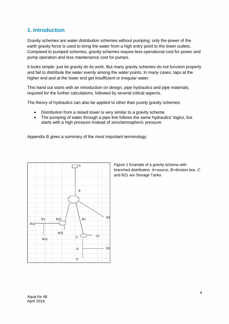
Gravity schemes are water distribution schemes without pumping; only the power of the earth gravity force is used to bring the water from a high entry point to the lower outlets. Compared to pumped schemes, gravity schemes require less operational cost for power and pump operation and less maintenance cost for pumps.
It looks simple: just let gravity do its work. But many gravity schemes do not function properly and fail to distribute the water evenly among the water points. In many cases, taps at the higher end and at the lower end get insufficient or irregular water.
This hand out starts with an introduction on design, pipe hydraulics and pipe materials, required for the further calculations, followed by several critical aspects.
The theory of hydraulics can also be applied to other than purely gravity schemes:
Distribution from a raised tower is very similar to a gravity scheme The pumping of water through a pipe line follows the same hydraulics’ logics, but
starts with a high pressure instead of zero/atmospheric pressure
Appendix B gives a summary of the most important terminology.
Figure 1 Example of a gravity scheme with branched distribution. A=source, B=division box, C and B21 are Storage Tanks
A
B
B2
B11
D
C
B3
E
B12B21B1
D1
C1B22
Aqua for All April 2014
5
2. Design
2.1 Preliminary work Most schemes exist of a central transmission main between an intake and the main Storage Tank. From the Storage Tank the water is distributed to water points (public or private). Most systems are so called closed systems (the water flow can be stopped by closing valves and taps). In case of abundant yield at the source and high pressure differences, an open system is recommended, where the flow in the pipelines is not interrupted by valves and taps. In this general instruction, the closed system is used as a reference, except when the exception of an open system is mentioned.
Appendix A provides a module to exercise the theory provided in this manual.
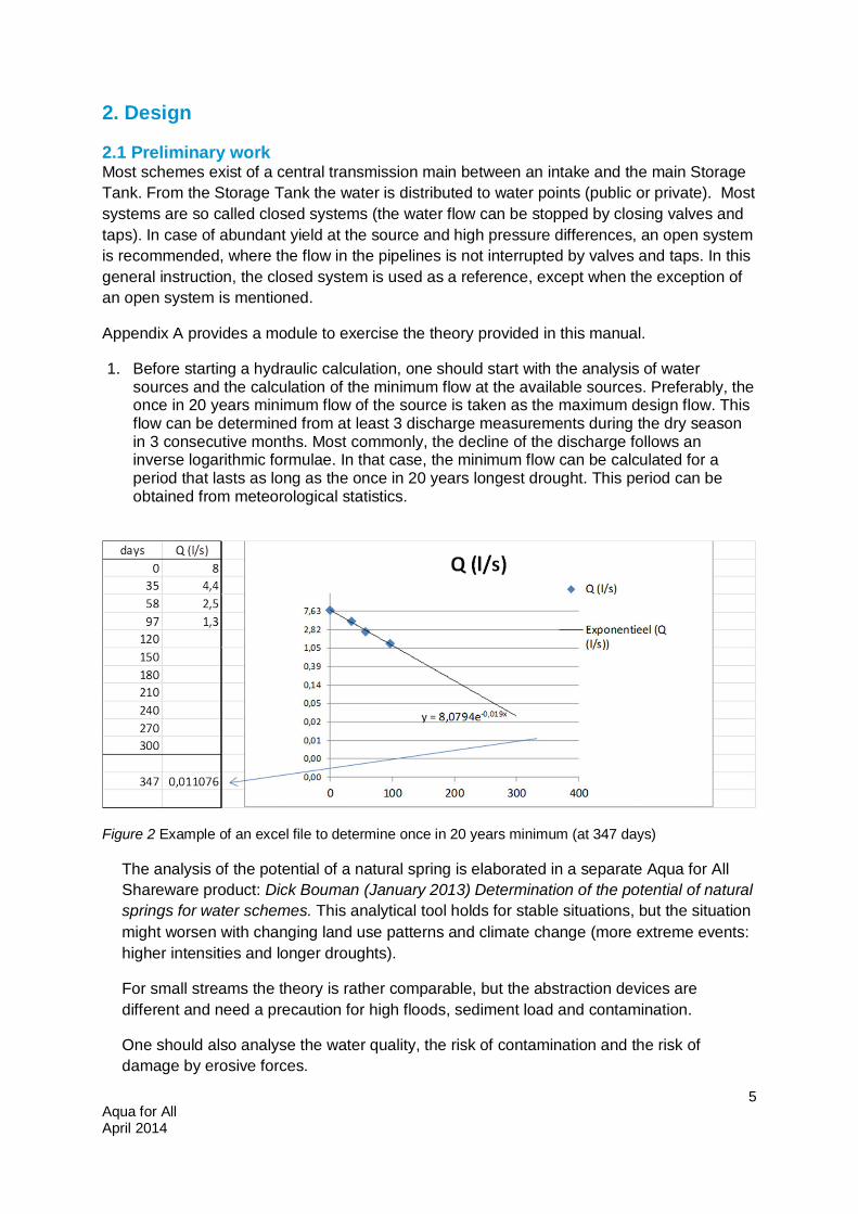
1. Before starting a hydraulic calculation, one should start with the analysis of water sources and the calculation of the minimum flow at the available sources. Preferably, the once in 20 years minimum flow of the source is taken as the maximum design flow. This flow can be determined from at least 3 discharge measurements during the dry season in 3 consecutive months. Most commonly, the decline of the discharge follows an inverse logarithmic formulae. In that case, the minimum flow can be calculated for a period that lasts as long as the once in 20 years longest drought. This period can be obtained from meteorological statistics.
Figure 2 Example of an excel file to determine once in 20 years minimum (at 347 days)
The analysis of the potential of a natural spring is elaborated in a separate Aqua for All Shareware product: Dick Bouman (January 2013) Determination of the potential of natural springs for water schemes. This analytical tool holds for stable situations, but the situation might worsen with changing land use patterns and climate change (more extreme events: higher intensities and longer droughts).
For small streams the theory is rather comparable, but the abstraction devices are different and need a precaution for high floods, sediment load and contamination.
One should also analyse the water quality, the risk of contamination and the risk of damage by erosive forces.
Aqua for All April 2014
6
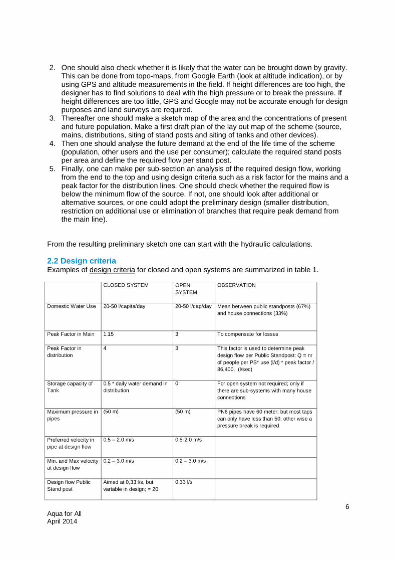
2. One should also check whether it is likely that the water can be brought down by gravity. This can be done from topo-maps, from Google Earth (look at altitude indication), or by using GPS and altitude measurements in the field. If height differences are too high, the designer has to find solutions to deal with the high pressure or to break the pressure. If height differences are too little, GPS and Google may not be accurate enough for design purposes and land surveys are required.
3. Thereafter one should make a sketch map of the area and the concentrations of present and future population. Make a first draft plan of the lay out map of the scheme (source, mains, distributions, siting of stand posts and siting of tanks and other devices).
4. Then one should analyse the future demand at the end of the life time of the scheme (population, other users and the use per consumer); calculate the required stand posts per area and define the required flow per stand post.
5. Finally, one can make per sub-section an analysis of the required design flow, working from the end to the top and using design criteria such as a risk factor for the mains and a peak factor for the distribution lines. One should check whether the required flow is below the minimum flow of the source. If not, one should look after additional or alternative sources, or one could adopt the preliminary design (smaller distribution, restriction on additional use or elimination of branches that require peak demand from the main line).
From the resulting preliminary sketch one can start with the hydraulic calculations.
2.2 Design criteria Examples of design criteria for closed and open systems are summarized in table 1.
CLOSED SYSTEM OPEN SYSTEM
OBSERVATION
Domestic Water Use 20-50 l/capita/day
20-50 l/cap/day Mean between public standposts (67%) and house connections (33%)
Peak Factor in Main 1.15 3 To compensate for losses
Peak Factor in distribution
4 3 This factor is used to determine peak design flow per Public Standpost: Q = nr of people per PS* use (l/d) * peak factor / 86,400. (l/sec)
Storage capacity of Tank
0.5 * daily water demand in distribution
0 For open system not required; only if there are sub-systems with many house connections
Maximum pressure in pipes
(50 m) (50 m) PN6 pipes have 60 meter; but most taps can only have less than 50; other wise a pressure break is required
Preferred velocity in pipe at design flow
0.5 – 2.0 m/s 0.5-2.0 m/s
Min. and Max velocity at design flow
0.2 – 3.0 m/s 0.2 – 3.0 m/s
Design flow Public Stand post
Aimed at 0,33 l/s, but variable in design; = 20
0.33 l/s
Aqua for All April 2014
7
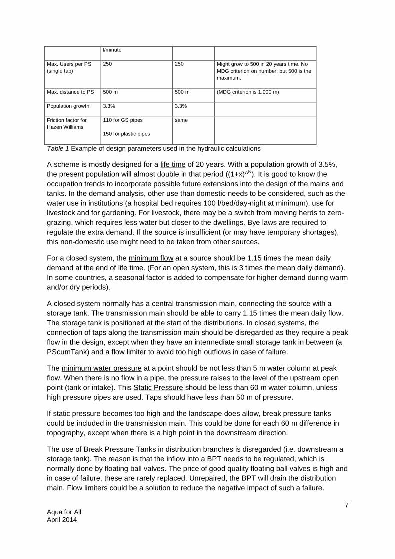
l/minute
Max. Users per PS (single tap)
250 250 Might grow to 500 in 20 years time. No MDG criterion on number; but 500 is the maximum.
Max. distance to PS 500 m 500 m (MDG criterion is 1.000 m)
Population growth 3.3% 3.3%
Friction factor for Hazen Williams
110 for GS pipes
150 for plastic pipes
same
Table 1 Example of design parameters used in the hydraulic calculations
A scheme is mostly designed for a life time of 20 years. With a population growth of 3.5%, the present population will almost double in that period ((1+x)^N). It is good to know the occupation trends to incorporate possible future extensions into the design of the mains and tanks. In the demand analysis, other use than domestic needs to be considered, such as the water use in institutions (a hospital bed requires 100 l/bed/day-night at minimum), use for livestock and for gardening. For livestock, there may be a switch from moving herds to zero-grazing, which requires less water but closer to the dwellings. Bye laws are required to regulate the extra demand. If the source is insufficient (or may have temporary shortages), this non-domestic use might need to be taken from other sources.
For a closed system, the minimum flow at a source should be 1.15 times the mean daily demand at the end of life time. (For an open system, this is 3 times the mean daily demand). In some countries, a seasonal factor is added to compensate for higher demand during warm and/or dry periods).
A closed system normally has a central transmission main, connecting the source with a storage tank. The transmission main should be able to carry 1.15 times the mean daily flow. The storage tank is positioned at the start of the distributions. In closed systems, the connection of taps along the transmission main should be disregarded as they require a peak flow in the design, except when they have an intermediate small storage tank in between (a PScumTank) and a flow limiter to avoid too high outflows in case of failure.
The minimum water pressure at a point should be not less than 5 m water column at peak flow. When there is no flow in a pipe, the pressure raises to the level of the upstream open point (tank or intake). This Static Pressure should be less than 60 m water column, unless high pressure pipes are used. Taps should have less than 50 m of pressure.
If static pressure becomes too high and the landscape does allow, break pressure tanks could be included in the transmission main. This could be done for each 60 m difference in topography, except when there is a high point in the downstream direction.
The use of Break Pressure Tanks in distribution branches is disregarded (i.e. downstream a storage tank). The reason is that the inflow into a BPT needs to be regulated, which is normally done by floating ball valves. The price of good quality floating ball valves is high and in case of failure, these are rarely replaced. Unrepaired, the BPT will drain the distribution main. Flow limiters could be a solution to reduce the negative impact of such a failure.
Aqua for All April 2014
8
Some schemes have Storage Tanks in series. In most cases this is not very efficient, as the downstream tanks constantly drain the upstream tank. In such cases, it can be more efficient to continue the main line to the downstream tank, bypassing the upstream tank. The division of flows between the two lines can be regulated through valves, or by a so-called division box.
For the distribution, one should include the peak factor to determine the design flow at each outflow point. For stand posts, normally a peak factor of 3 – 4 is used, to compensate for the uneven distribution of demand during the day. For institutions, houses and irrigation, the peak factor may be different.
There are 2 principle lay-outs:
Branched systems Looped systems
A variation is a looped ring, to which branched systems are connected, with or without secondary storage tanks. Advantage of a looped system is a better response to peak demands and the possibility to continue the water supply during maintenance works along the main. It is mostly a bit more costly, and more complicated to calculate without a computer programme.
In this manual, only the branched system is elaborated.
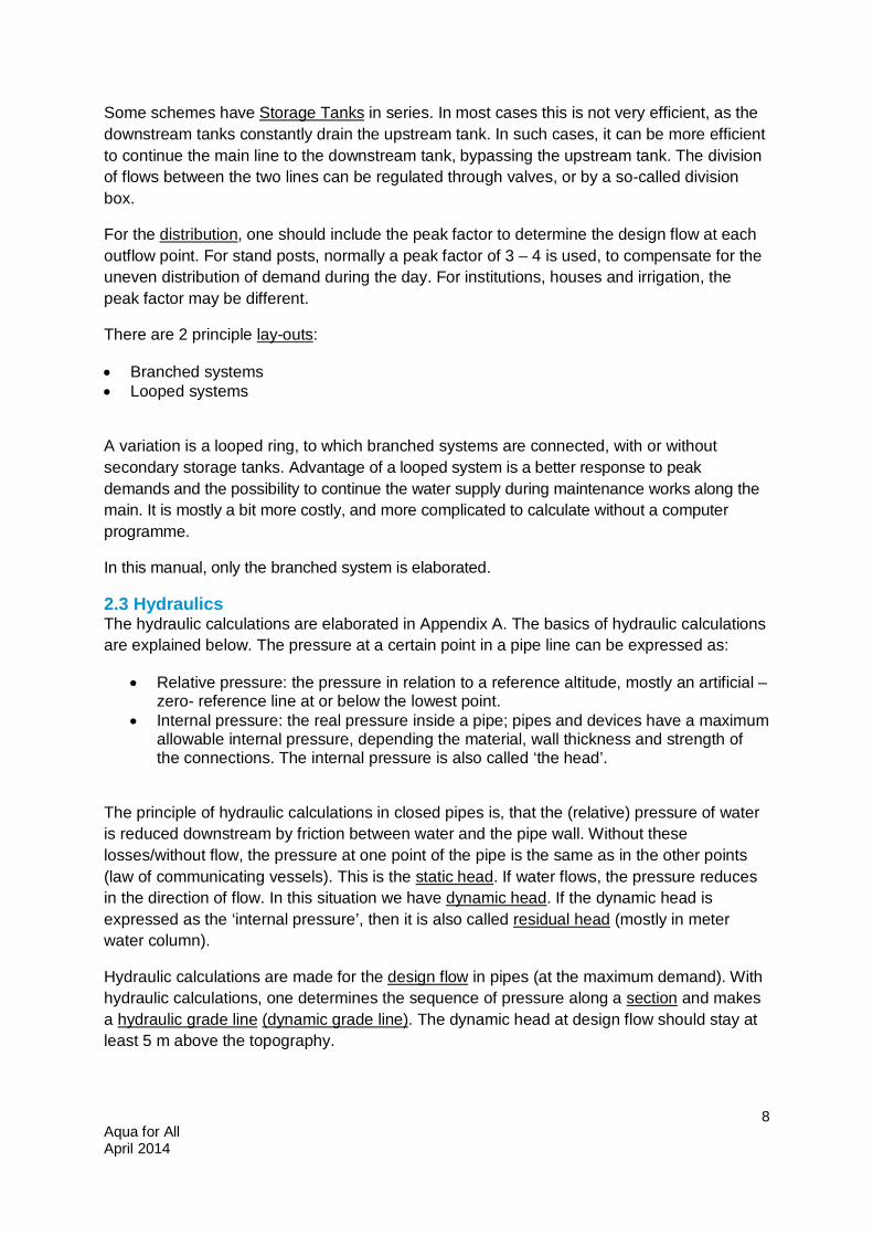
2.3 Hydraulics The hydraulic calculations are elaborated in Appendix A. The basics of hydraulic calculations are explained below. The pressure at a certain point in a pipe line can be expressed as:
Relative pressure: the pressure in relation to a reference altitude, mostly an artificial –zero- reference line at or below the lowest point.
Internal pressure: the real pressure inside a pipe; pipes and devices have a maximum allowable internal pressure, depending the material, wall thickness and strength of the connections. The internal pressure is also called ‘the head’.
The principle of hydraulic calculations in closed pipes is, that the (relative) pressure of water is reduced downstream by friction between water and the pipe wall. Without these losses/without flow, the pressure at one point of the pipe is the same as in the other points (law of communicating vessels). This is the static head. If water flows, the pressure reduces in the direction of flow. In this situation we have dynamic head. If the dynamic head is expressed as the ‘internal pressure’, then it is also called residual head (mostly in meter water column).
Hydraulic calculations are made for the design flow in pipes (at the maximum demand). With hydraulic calculations, one determines the sequence of pressure along a section and makes a hydraulic grade line (dynamic grade line). The dynamic head at design flow should stay at least 5 m above the topography.
Aqua for All April 2014
9
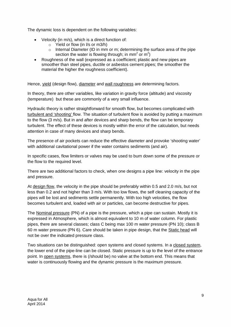
The dynamic loss is dependent on the following variables:
Velocity (in m/s), which is a direct function of: o Yield or flow (in l/s or m3/h) o Internal Diameter (ID in mm or m; determining the surface area of the pipe
section the water is flowing through; in mm2 or m2) Roughness of the wall (expressed as a coefficient; plastic and new pipes are
smoother than steel pipes, ductile or asbestos cement pipes; the smoother the material the higher the roughness coefficient).
Hence, yield (design flow), diameter and wall roughness are determining factors.
In theory, there are other variables, like variation in gravity force (altitude) and viscosity (temperature) but these are commonly of a very small influence.
Hydraulic theory is rather straightforward for smooth flow, but becomes complicated with turbulent and ‘shooting’ flow. The situation of turbulent flow is avoided by putting a maximum to the flow (3 m/s). But in and after devices and sharp bends, the flow can be temporary turbulent. The effect of these devices is mostly within the error of the calculation, but needs attention in case of many devices and sharp bends.
The presence of air pockets can reduce the effective diameter and provoke ‘shooting water’ with additional cavitational power if the water contains sediments (and air).
In specific cases, flow limiters or valves may be used to burn down some of the pressure or the flow to the required level.
There are two additional factors to check, when one designs a pipe line: velocity in the pipe and pressure.
At design flow, the velocity in the pipe should be preferably within 0.5 and 2.0 m/s, but not less than 0.2 and not higher than 3 m/s. With too low flows, the self cleaning capacity of the pipes will be lost and sediments settle permanently. With too high velocities, the flow becomes turbulent and, loaded with air or particles, can become destructive for pipes.
The Nominal pressure (PN) of a pipe is the pressure, which a pipe can sustain. Mostly it is expressed in Atmosphere, which is almost equivalent to 10 m of water column. For plastic pipes, there are several classes; class C being max 100 m water pressure (PN 10); class B 60 m water pressure (PN 6). Care should be taken in pipe design, that the Static head will not be over the indicated pressure class.
Two situations can be distinguished: open systems and closed systems. In a closed system, the lower end of the pipe-line can be closed. Static pressure is up to the level of the entrance point. In open systems, there is (/should be) no valve at the bottom end. This means that water is continuously flowing and the dynamic pressure is the maximum pressure.
Aqua for All April 2014
10
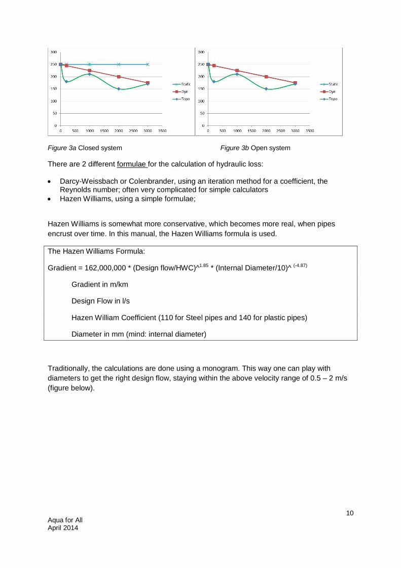
Figure 3a Closed system Figure 3b Open system
There are 2 different formulae for the calculation of hydraulic loss:
Darcy-Weissbach or Colenbrander, using an iteration method for a coefficient, the Reynolds number; often very complicated for simple calculators
Hazen Williams, using a simple formulae;
Hazen Williams is somewhat more conservative, which becomes more real, when pipes encrust over time. In this manual, the Hazen Williams formula is used.
The Hazen Williams Formula:
Gradient = 162,000,000 * (Design flow/HWC)^1.85 * (Internal Diameter/10)^ (-4.87)
Gradient in m/km
Design Flow in l/s
Hazen William Coefficient (110 for Steel pipes and 140 for plastic pipes)
Diameter in mm (mind: internal diameter)
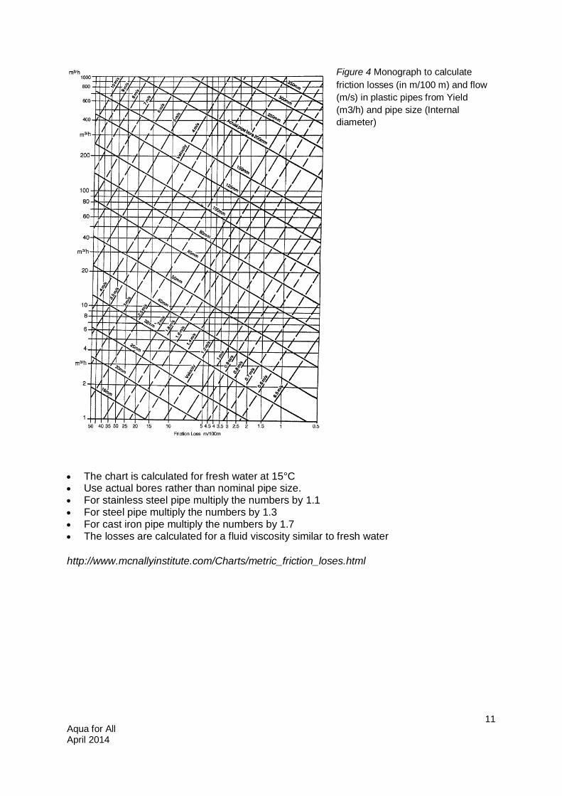
Traditionally, the calculations are done using a monogram. This way one can play with diameters to get the right design flow, staying within the above velocity range of 0.5 – 2 m/s (figure below).
Aqua for All April 2014
11
Figure 4 Monograph to calculate friction losses (in m/100 m) and flow (m/s) in plastic pipes from Yield (m3/h) and pipe size (Internal diameter)
The chart is calculated for fresh water at 15°C Use actual bores rather than nominal pipe size. For stainless steel pipe multiply the numbers by 1.1 For steel pipe multiply the numbers by 1.3 For cast iron pipe multiply the numbers by 1.7 The losses are calculated for a fluid viscosity similar to fresh water
http://www.mcnallyinstitute.com/Charts/metric_friction_loses.html
Aqua for All April 2014
12
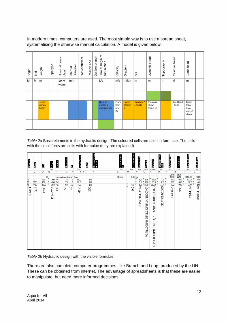
In modern times, computers are used. The most simple way is to use a spread sheet, systematising the otherwise manual calculation. A model is given below.
Beg
in
End
Leng
th
Pip
e ty
pe
Nom
inal
pre
ss
clas
s
Inte
rnal
D
iam
eter
HW
Coe
ffici
ent
Rea
son
end
Out
flow
bra
nch
Flow
at b
egin
of
sub-
sect
ion
Vel
ocity
Gra
dien
t
DH
Dyn
amic
Hea
d
Topo
grap
hy
Res
idua
l hea
d
Sta
tic h
ead
M M m 10 M water
mm L/s m/s m/km m m m M m
= end minus begin
Sum of outflows downstream
From flow and ID
Hazen Wiiliams
Gradient * Length
Pressure above minus DH
Dyn Head - Topo
Begin topo – topo end of chain
Table 2a Basic elements in the hydraulic design. The coloured cells are used in formulae. The cells with the small fonts are cells with formulae (they are explained)
Table 2b Hydraulic design with the visible formulae
There are also complete computer programmes, like Branch and Loop, produced by the UN. These can be obtained from internet. The advantage of spreadsheets is that these are easier to manipulate, but need more informed decisions.
(m) (mm) (l/s) (l/s) (l/s) (m/s) (m/km) (m) (m) (m) (m) (m)C D E F G H I J K L M N O P Q R S T U
1100 11000 calculation design flow Qpipe 5,00 l/s 1000 1000 1000,00 1000
1 0 300 300 PV 75 6 68,0 150 5,0 1,38 26,5 7,9 992 940 52,06 602 300 750 450 PV 75 6 68,0 150 5,0 1,38 26,5 11,9 980 960 20,16 403 750 1000 250 PE 50 10 41,0 150 5,0 5,0 3,79 310,9 77,7 902 900 2,44 100
B13+
1
D13
1200
D14
-C14 PE 50 10
41,0
150
0,0
P15+
N14
+O14
P14/
(100
0*0,
25*3
,142
*(K1
4/10
00)^
2)
1620
0000
0*(P
14/L
14)^
1,85
*(K1
4/10
)^(-
4,87
)
G14
*R14
/100
0
T13-
S14
900
T14-
U14
U$1
0-U
14
Aqua for All April 2014
13
Procedure:
1. One starts to divide the full section into different chainages (sub-sections), normally split at the highest points or at indicated special points with a proposed branch and stretches where it is known that special pipes are required (such as GI pipes in a valley crossing; or where high pressure pipes are required).
2. The line with formulae in the spread sheet needs to be copied as many times as the number of sub-sections.
3. Above the first line one adds the elevation of the source or starting point at Dynamic head and Topography.
4. Below the last line one fills in the design outflow (green cell). 5. For each sub-section one fills in the End distance from the zero point (the Begin is
calculated), or Length; the design outflow into a branch at the begin of the sub-section and the topography.
6. The rest is an iterative process by trial and error, filling in the Internal Diameter. The best result is reached if:
a. there is no point with less than 5 m residual head b. there is no line with velocity between 0.2 and 3.0 m/s c. there is no static pressure which is above the pipe pressure class d. the residual head at the final point is as close as possible to 5 m*
7. Now, the reached Internal Diameters are translated to real pipe sizes of the required quality and type. This needs another iterative round.
If the residual head at the final point is much higher than 5 meter, the system will react in a way that it will increase the flow till the hydraulic losses have reached the situation that the residual head at the final point becomes zero. This may result in a situation where the optimum flow becomes higher than the inflow at the source. Then air will be attracted into the system, which will provoke a lot of hydraulic problems. Therefore it is always required to burn off the pressure in the last part of the section to reach almost zero residual head at the outflow point.
In most cases it is desirable that, between an inlet and an outlet point, downstream pipe sizes are smaller than upstream sizes.
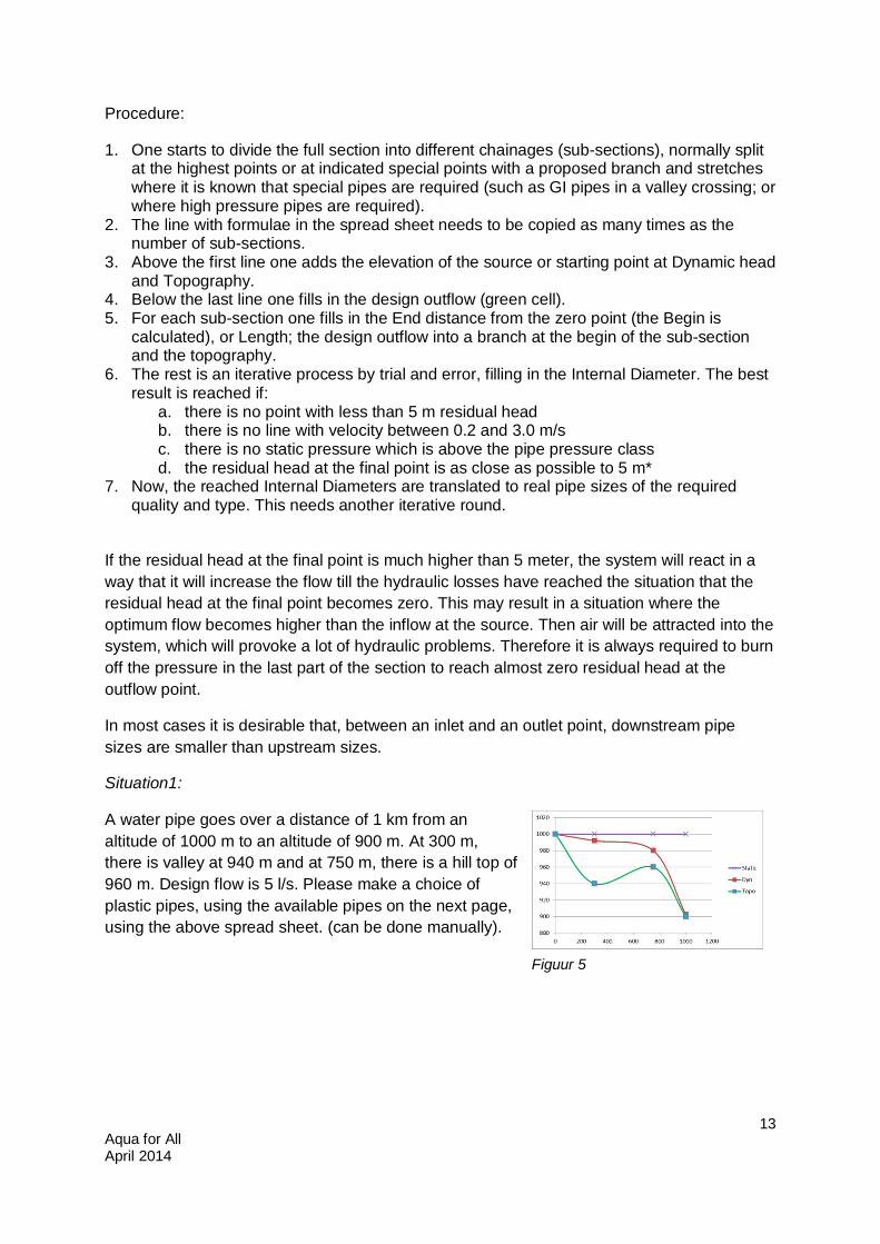
Situation1:
A water pipe goes over a distance of 1 km from an altitude of 1000 m to an altitude of 900 m. At 300 m, there is valley at 940 m and at 750 m, there is a hill top of 960 m. Design flow is 5 l/s. Please make a choice of plastic pipes, using the available pipes on the next page, using the above spread sheet. (can be done manually).
Figuur 5
Aqua for All April 2014
14
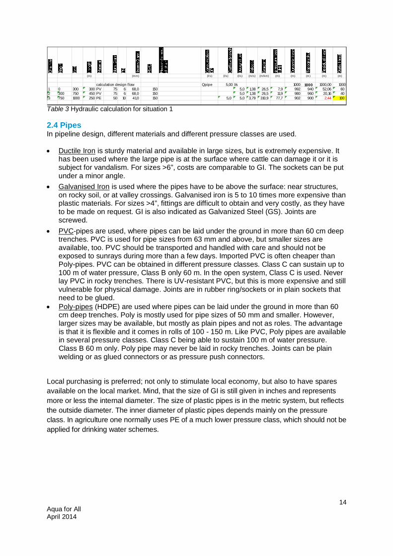
Table 3 Hydraulic calculation for situation 1
2.4 Pipes In pipeline design, different materials and different pressure classes are used.
Ductile Iron is sturdy material and available in large sizes, but is extremely expensive. It has been used where the large pipe is at the surface where cattle can damage it or it is subject for vandalism. For sizes >6”, costs are comparable to GI. The sockets can be put under a minor angle.
Galvanised Iron is used where the pipes have to be above the surface: near structures, on rocky soil, or at valley crossings. Galvanised iron is 5 to 10 times more expensive than plastic materials. For sizes >4”, fittings are difficult to obtain and very costly, as they have to be made on request. GI is also indicated as Galvanized Steel (GS). Joints are screwed.
PVC-pipes are used, where pipes can be laid under the ground in more than 60 cm deep trenches. PVC is used for pipe sizes from 63 mm and above, but smaller sizes are available, too. PVC should be transported and handled with care and should not be exposed to sunrays during more than a few days. Imported PVC is often cheaper than Poly-pipes. PVC can be obtained in different pressure classes. Class C can sustain up to 100 m of water pressure, Class B only 60 m. In the open system, Class C is used. Never lay PVC in rocky trenches. There is UV-resistant PVC, but this is more expensive and still vulnerable for physical damage. Joints are in rubber ring/sockets or in plain sockets that need to be glued.
Poly-pipes (HDPE) are used where pipes can be laid under the ground in more than 60 cm deep trenches. Poly is mostly used for pipe sizes of 50 mm and smaller. However, larger sizes may be available, but mostly as plain pipes and not as roles. The advantage is that it is flexible and it comes in rolls of 100 - 150 m. Like PVC, Poly pipes are available in several pressure classes. Class C being able to sustain 100 m of water pressure. Class B 60 m only. Poly pipe may never be laid in rocky trenches. Joints can be plain welding or as glued connectors or as pressure push connectors.
Local purchasing is preferred; not only to stimulate local economy, but also to have spares available on the local market. Mind, that the size of GI is still given in inches and represents more or less the internal diameter. The size of plastic pipes is in the metric system, but reflects the outside diameter. The inner diameter of plastic pipes depends mainly on the pressure class. In agriculture one normally uses PE of a much lower pressure class, which should not be applied for drinking water schemes.
(m) (mm) (l/s) (l/s) (l/s) (m/s) (m/km) (m) (m) (m) (m) (m)
calculation design flow Qpipe 5,00 l/s 1000 1000 1000,00 10001 0 300 300 PV 75 6 68,0 150 5,0 1,38 26,5 7,9 992 940 52,06 602 300 750 450 PV 75 6 68,0 150 5,0 1,38 26,5 11,9 980 960 20,16 403 750 1000 250 PE 50 10 41,0 150 5,0 5,0 3,79 310,9 77,7 902 900 2,44 100
Aqua for All April 2014
15
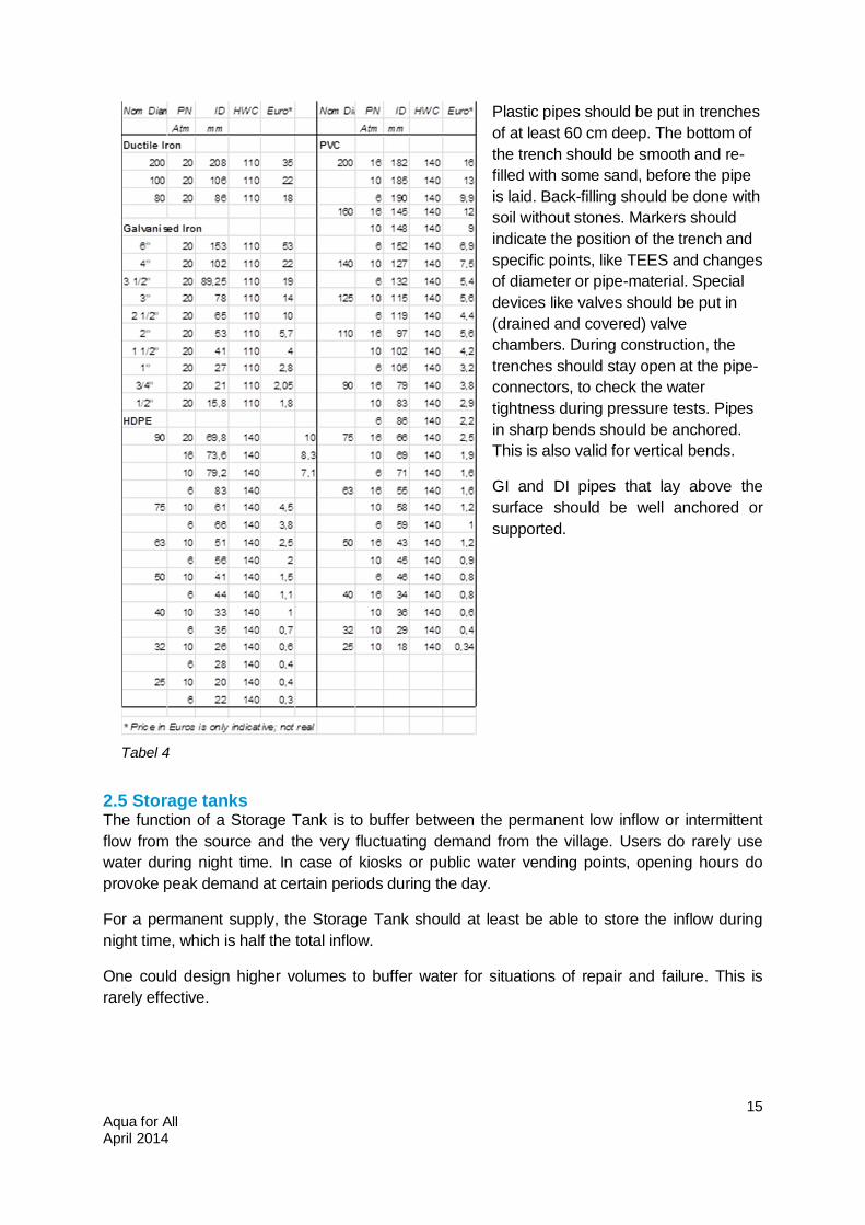
Plastic pipes should be put in trenches of at least 60 cm deep. The bottom of the trench should be smooth and re-filled with some sand, before the pipe is laid. Back-filling should be done with soil without stones. Markers should indicate the position of the trench and specific points, like TEES and changes of diameter or pipe-material. Special devices like valves should be put in (drained and covered) valve chambers. During construction, the trenches should stay open at the pipe-connectors, to check the water tightness during pressure tests. Pipes in sharp bends should be anchored. This is also valid for vertical bends.
GI and DI pipes that lay above the surface should be well anchored or supported.
2.5 Storage tanks The function of a Storage Tank is to buffer between the permanent low inflow or intermittent flow from the source and the very fluctuating demand from the village. Users do rarely use water during night time. In case of kiosks or public water vending points, opening hours do provoke peak demand at certain periods during the day.
For a permanent supply, the Storage Tank should at least be able to store the inflow during night time, which is half the total inflow.
One could design higher volumes to buffer water for situations of repair and failure. This is rarely effective.
Tabel 4
Aqua for All April 2014
16
Storage tanks need a wash-out at the bottom (for cleaning), an overflow at the top (to spill excess water) a ventilation opening and a manhole. Tanks need roofs to prevent dust, leaves, animals and insects from entering and to avoid algae bloom.
Some details for the design:
the wash-out should be at the lowest point distribution lines should have their own outlet (and valve) each Tanks should be roofed. In case of circular design, supporting columns might be required
(for both concrete and metal sheet roofs). there should be a man-hole in one of the walls for entering, or a manhole on top, in which
drainage water is prevented from entering.
2.6 Other Devices In pipe line design, four more devices are important.
The intake structure has to be specifically designed for the natural situation. Natural springs are the best, but still need a good protection. Surface water intakes in streams need specific attention to minimize the inflow of mud, sands and debris. Both need a strainer, which is to be inspected (and cleaned) on a daily basis.
One needs to make a pre-survey of the minimum flow in a source. Mostly, the once in 10 or 20 years minimum flow should be above the required design flow (mostly the mean demand over 20 years). The determination of the minimum flow is to be based on at least three measurements during the same dry season. (see further in Bouman, January 2013a)
In both cases, a nearby collection or pre-sedimentation tank is recommended. In case of risk of contamination, further treatment is required. For turbid water, treatment is done close to the source to avoid clogging in the main. For water that is contaminated with pathogens, various treatments can be applied from sedimentation and filtration to chlorination. It is beyond the subject of this reader to deal with this issue.
A break pressure tank can interrupt the pressure and break it down to zero. This is important, when pressure would come too high. Care should be taken not to design the capacity of the downstream pipe to be (much) higher than that of the upper pipe. In that case, the pipe will suck air and the downstream part will get problems with air locks (see later). Break pressure tanks are mostly made along main lines. Their use in distribution systems is not recommended, as they will counteract the effect of a storage tank. Except when a float valve is used, but these float valves need a lot of maintenance and are very costly. One might also Break Pressure Valves or other devices, but these are vulnerable for clogging.
Automatic air release valves. It is difficult to avoid the entrance of air into a pipe line. Natural water contains air, which is released under certain pressure circumstances. Furthermore, over-capacity of the pipe may suck air at the entrance point. Air may accumulate in the course of the pipe-line, especially at the highest points, at reducers, or deflections. In mains, air valves are mostly placed at these critical spots. Or at least one in 1.5 km, especially where the terrain is (semi-) horizontal. Generally it is recommended to try to change the slope of the pipe line once in a while, instead of maintaining its slope equal for a long time. Also break pressure tanks and well positioned standposts may function as air release devices. Or one may bring up a branch
Aqua for All April 2014
17
higher up to an adjacent hill slope (if available). The latter and break pressure tanks, may also suck air into the pipe in case of under pressure, which is a disadvantage.
Wash outs are positioned at each lower point of a pipe line, or where one can expect the accumulation of sediment. Wash outs are gate valves, mounted on the TEE-branch to a main. It is regularly opened to clean the pipe.
2.7 Valves There are several types of valves:
Air-valves have been installed at points where air may accumulate. Float valves in tanks, which automatically regulate the inflow of water. The closing
mechanism is a pin, which enters into the pipe. It is linked to a ball, which floats on the water. But don’t mix them up with ball valves. Float valves are expensive and need regular replacement. Critical element is the spindle.
Ball valves. These valves have a ball inside with a drilled hole. The valve is open, when this drilled hole is in line with the pipe. Turning the handle one quarter, which brings the drilled hole perpendicular to the pipe, can close the valve. This type of valve is used near standposts, or at the inlet or as a bib-cock. It can be recognised by a handle. It is not used in mains, because they close pipes abruptly, which may cause the damaging of pipes by pressure waves.
Gate valves. These valves have a metal plate inside, which can slowly shut off the flow, when the wheel (held by a spindle) is (slowly) turned clock-wise. These valves may be used as control valves at the back of standposts and in the mains. They are also used in wash-outs. To a limited extend they can be used to control the quantity of flow. Gate valves need to be opened and closed regularly, to keep them operational.
Globe valves. These are used to control the flow more accurately and to burn down the pressure. The water is lead in a very complicated way through the valve. Stopcocks are mostly globe valve types.
Aqua for All April 2014
18
3. Specific Issues
There are 4 main problems with pipe-lines: too high pressure, air locks, water hammer and distribution of flow at TEES.
3.1 Too high pressures As indicated before, too high pressures can be responded by applying pipes with higher pressure class, inclusion of Break Pressure Tanks, mechanical Pressure Reducers, burning down pressure with valves or applying an open system without valves in part of the main. BPTs and pressure reducer valves are not very effective in case of low flow, while Break Pressure Tanks are preferably not applied in distribution mains.
An alternative solution is the use of an ‘open system’, or at least a minimum outflow at the lower end or at certain overflow points. This can only be done with sufficient water.
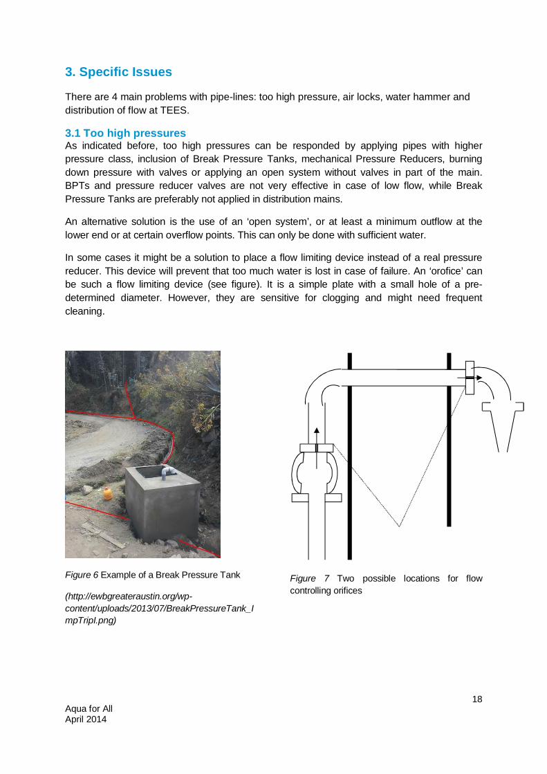
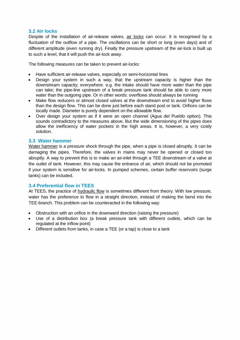
In some cases it might be a solution to place a flow limiting device instead of a real pressure reducer. This device will prevent that too much water is lost in case of failure. An ‘orofice’ can be such a flow limiting device (see figure). It is a simple plate with a small hole of a pre-determined diameter. However, they are sensitive for clogging and might need frequent cleaning.
Figure 6 Example of a Break Pressure Tank
(http://ewbgreateraustin.org/wp-content/uploads/2013/07/BreakPressureTank_ImpTripI.png)
Figure 7 Two possible locations for flow controlling orifices
3.2 Air locks Despite of the installation of air-release valves, air locks can occur. It is recognised by a fluctuation of the outflow of a pipe. The oscillations can be short or long (even days) and of different amplitude (even running dry). Finally the pressure upstream of the air-lock is built up to such a level, that it will push the air-lock away.
The following measures can be taken to prevent air-locks:
Have sufficient air-release valves, especially on semi-horizontal lines Design your system in such a way, that the upstream capacity is higher than the
downstream capacity; everywhere. e.g. the intake should have more water than the pipe can take; the pipe-line upstream of a break pressure tank should be able to carry more water than the outgoing pipe. Or in other words: overflows should always be running
Make flow reducers or almost closed valves at the downstream end to avoid higher flows than the design flow. This can be done just before each stand post or tank. Orifices can be locally made. Diameter is purely dependent on the allowable flow.
Over design your system as if it were an open channel (Agua del Pueblo option). This sounds contradictory to the measures above. But the wide dimensioning of the pipes does allow the inefficiency of water pockets in the high areas. It is, however, a very costly solution.
3.3 Water hammer Water hammer is a pressure shock through the pipe, when a pipe is closed abruptly. It can be damaging the pipes. Therefore, the valves in mains may never be opened or closed too abruptly. A way to prevent this is to make an air-inlet through a TEE downstream of a valve at the outlet of tank. However, this may cause the entrance of air, which should not be promoted if your system is sensitive for air-locks. In pumped schemes, certain buffer reservoirs (surge tanks) can be included.
3.4 Preferential flow in TEES At TEES, the practice of hydraulic flow is sometimes different from theory. With low pressure, water has the preference to flow in a straight direction, instead of making the bend into the TEE-branch. This problem can be counteracted in the following way:
Obstruction with an orifice in the downward direction (raising the pressure) Use of a distribution box (a break pressure tank with different outlets, which can be
regulated at the inflow point) Different outlets from tanks, in case a TEE (or a tap) is close to a tank
Aqua for All April 2014
20
4. Final Remarks
Water supply schemes need to be managed professionally. Simple schemes in one village with a few public taps might be managed and operated by a community water committee. More complex schemes, however, require a well thought management structure with legal status and service contracts for the more complicated aspects. More information can be found in another Aqua for All Shareware product (D.Bouman (2013c) Institutional models ).
Maintenance requirements of gravity schemes are limited, but should not be overlooked. In case of treatment plants, operation and maintenance is demanding. Scheme attendants are also required for intake inspection, management of valves and tanks, maintenance of the distribution system and for the water meter reading and fee collection.
Costs include investment (and replacement), repair/maintenance and operation costs. Preferably, one includes the cost for replacement, extension and upgrading in the unit price.
Other issues:
By bringing water to homes (or to inhabited places) one creates a drainage problem. Sanitation should make an integral part of a water supply project.
Water supply is often a new technology. Hygiene, water storage at home, regulations about irrigation etc. should be discussed and communicated with the (future) users. Education is often required. Contracts may define the details.
Users have to be considered as clients or owners of the system, not as beneficiaries. Improvement of the ownership can be reached by involving the users in project planning and management and by asking an initial financial contribution. Water utilities need to see the users as clients, and proper communication is required. For example on tariffs, billing, planned maintenance routines etc. A proper ‘complaints procedure’ should be in place.
There is a need for a decision on contracting out or doing everything internally. There are several systems for fee collection. Fee collection in mixed private and public tap
systems is very problematic. There is a separate AquaShareware product on institutional models for rural water supply schemes.
Aqua for All April 2014
21
References
Dick Bouman (2013) Determination of the potential of natural springs for water schemes (an AquaShareware product) Dick Bouman (2014) Institutional models for rural water schemes (an Aquashareware product; still to be published) Thomas Jordan (1980) Handbook of gravity flow water systems (Nepal) Corcos, Gilles (1992) Air in Water Pipes, (Aqua para la Vida)
Aqua for All April 2014
22
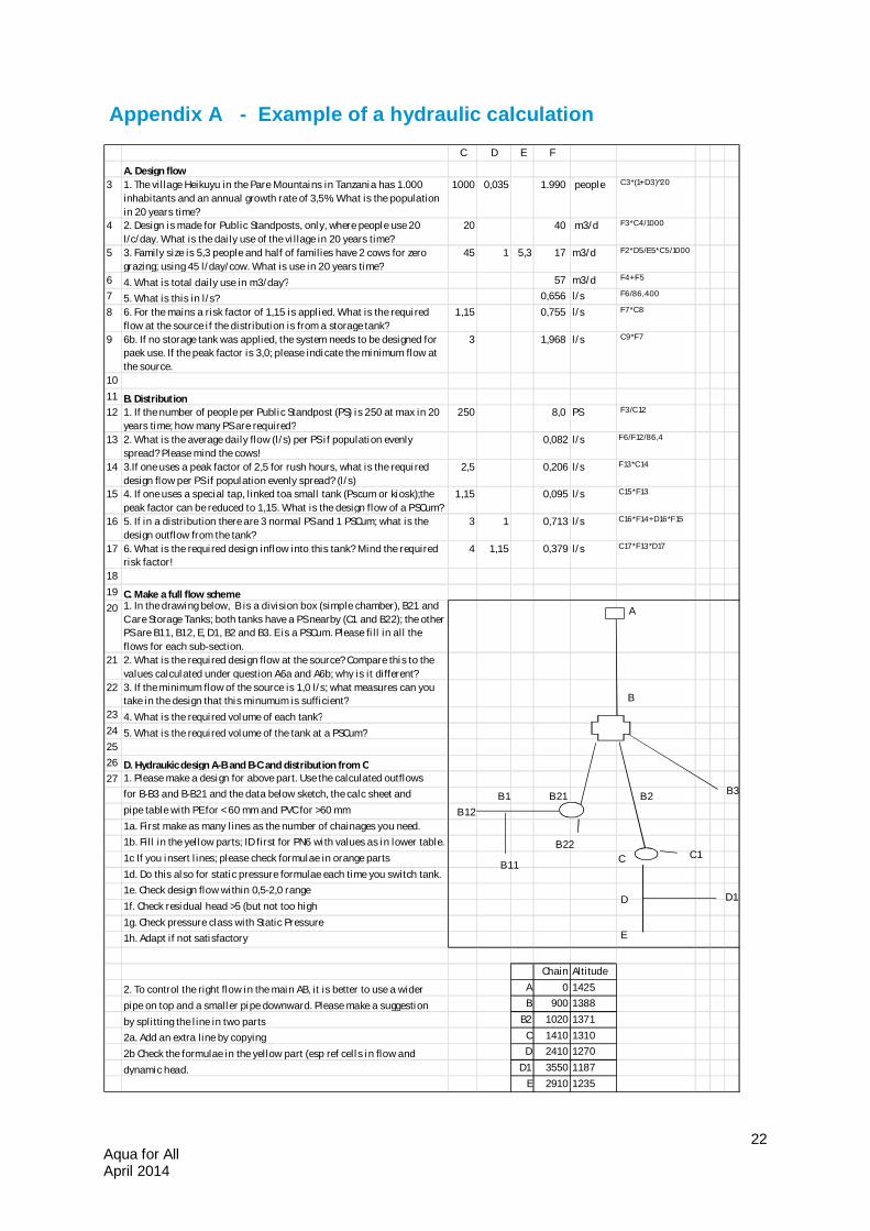
Appendix A - Example of a hydraulic calculation
C D E F
A. Design flow3 1. The village Heikuyu in the Pare Mountains in Tanzania has 1.000
inhabitants and an annual growth rate of 3,5%. What is the population in 20 years time?
1000 0,035 1.990 people C3*(1+D3) 2̂0
4 2. Design i s made for Public Standposts, only, where people use 20 l/c/day. What is the dai ly use of the vi llage in 20 years time?
20 40 m3/d F3*C4/1000
5 3. Family size is 5,3 people and half of families have 2 cows for zero grazing; using 45 l/day/cow. What is use in 20 years time?
45 1 5,3 17 m3/d F2*D5/E5*C5/1000
6 4. What is total daily use in m3/day? 57 m3/d F4+F5
7 5. What is this in l/s? 0,656 l/s F6/86,400
8 6. For the mains a risk factor of 1,15 i s applied. What is the required flow at the source i f the distribution is from a storage tank?
1,15 0,755 l/s F7*C8
9 6b. If no storage tank was applied, the system needs to be designed for paek use. If the peak factor is 3,0; please indicate the minimum flow at the source.
3 1,968 l/s C9*F7
1011 B. Distribution12 1. If the number of people per Public Standpost (PS) i s 250 at max in 20
years time; how many PS are required?250 8,0 PS F3/C12
13 2. What is the average daily flow (l/s) per PS i f population evenly spread? Please mind the cows!
0,082 l/s F6/F12/86,4
14 3.If one uses a peak factor of 2,5 for rush hours, what is the required design flow per PS if population evenly spread? (l/s)
2,5 0,206 l/s F13*C14
15 4. If one uses a special tap, linked toa small tank (Pscum or kiosk);the peak factor can be reduced to 1,15. What is the design flow of a PSCum?
1,15 0,095 l/s C15*F13
16 5. If in a distribution there are 3 normal PS and 1 PSCum; what is the design outflow from the tank?
3 1 0,713 l/s C16*F14+D16*F15
17 6. What is the required design inflow into this tank? Mind the required risk factor!
4 1,15 0,379 l/s C17*F13*D17
1819 C. Make a full flow scheme20 1. In the drawing below, B is a division box (simple chamber), B21 and
C are Storage Tanks; both tanks have a PS nearby (C1 and B22); the other PS are B11, B12, E, D1, B2 and B3. E is a PSCum. Please fi ll in all the flows for each sub-section.
21 2. What is the required design flow at the source? Compare this to the values calculated under question A6a and A6b; why is it different?
22 3. If the minimum flow of the source is 1,0 l/s; what measures can you take in the design that this minumum is sufficient?
23 4. What is the required volume of each tank?24 5. What is the required volume of the tank at a PSCum?2526 D. Hydraukic design A-B and B-C and distribution from C27 1. Please make a design for above part. Use the calculated outflows
for B-B3 and B-B21 and the data below sketch, the calc sheet and pipe table with PE for < 60 mm and PVC for >60 mm1a. First make as many l ines as the number of chainages you need.1b. Fill in the yellow parts; ID first for PN6 with values as in lower table.1c If you insert l ines; please check formulae in orange parts1d. Do this also for static pressure formulae each time you switch tank.1e. Check design flow within 0,5-2,0 range1f. Check residual head >5 (but not too high1g. Check pressure class with Static Pressure1h. Adapt if not satisfactory
Chain Altitude
2. To control the right flow in the main AB, it is better to use a wider A 0 1425
pipe on top and a smaller pipe downward. Please make a suggestion B 900 1388
by splitting the l ine in two parts B2 1020 1371
2a. Add an extra line by copying C 1410 1310
2b Check the formulae in the yellow part (esp ref cell s in flow and D 2410 1270
dynamic head. D1 3550 1187E 2910 1235
A
B
B2
B11
D
C
B3
E
B12B21B1
D1
C1B22
Aqua for All April 2014
23
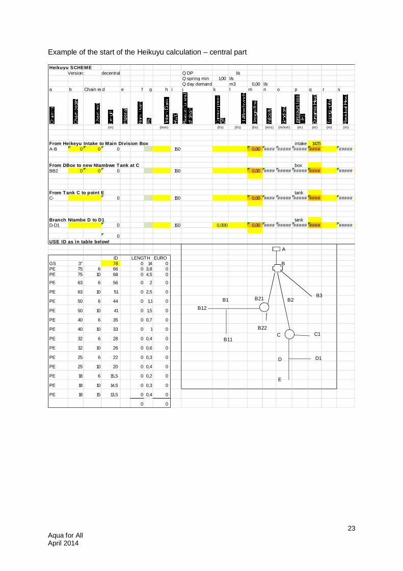
Example of the start of the Heikuyu calculation – central part
Heikuyu SCHEME Version: decentral Q DP l/s
Q spring min 1,00 l/sQ day demand m3 0,00 l/s
a b Chain endd e f g h i j k l m n o p q r s
(m) (mm) (l/s) (l/s) (l/s) (m/s) (m/km) (m) (m) (m) (m)
From Heikeyu Intake to Main Division Box intake 1425A-B 0 0 0 150 0,00 #### ##### ##### #### #####
From DBox to new Ntambwe Tank at C boxBB2 0 0 0 150 0,00 #### ##### ##### #### #####
From Tank C to point E tankC- 0 150 0,00 #### ##### ##### #### #####
Branch Ntambe D to D1 tankD-D1 0 150 0,000 0,00 #### ##### ##### #### #####
0USE ID as in table below!
ID LENGTH EUROGS 3" 78 0 14 0PE 75 6 66 0 3,8 0PE 75 10 68 0 4,5 0
PE 63 6 56 0 2 0
PE 63 10 51 0 2,5 0
PE 50 6 44 0 1,1 0
PE 50 10 41 0 1,5 0
PE 40 6 35 0 0,7 0
PE 40 10 33 0 1 0
PE 32 6 28 0 0,4 0
PE 32 10 26 0 0,6 0
PE 25 6 22 0 0,3 0
PE 25 10 20 0 0,4 0
PE 18 6 15,5 0 0,2 0
PE 18 10 14,5 0 0,3 0
PE 18 15 13,5 0 0,4 0
0 0
A
B
B2
B11
D
C
B3
E
B12
B21B1
D1
C1B22
Aqua for All April 2014
24
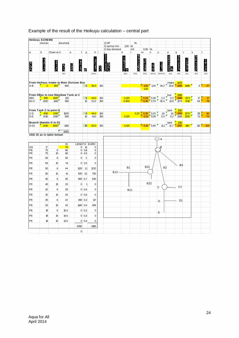
Example of the result of the Heikuyu calculation – central part
Heikeyu SCHEME Version: decentral Q DP l/s
Q spring min 1,00 l/sQ day demand m3 0,00 l/s
a b Chain endd e f g h i j k l m n o p q r s t
(m) (mm) (l/s) (l/s) (l/s) (m/s) (m/km) (m) (m) (m) (m) (m)
From Heikeyu Intake to Main Division Box intake 1425A-B 0 900 900 6 35,0 150 1,00 1,04 34,2 30,8 1394 1388 6 37
1,00
From DBox to new Ntambwe T ank at C box 1388BB2 900 1020 120 6 44,0 150 0,125 0,43 0,28 2,3 0,3 1388 1371 17 17B2-C 1020 1410 390 10 22,0 150 0,300 0,30 0,79 35,4 13,8 1374 1310 64 78
From T ank C to point E tank 1310C-D 1410 2410 1000 6 44,0 150 0,23 0,35 0,23 1,6 1,6 1308 1270 38 40D-E 2410 2910 500 10 41,0 150 0,125 0,13 0,09 0,3 0,2 1308 1235 73 75
Branch Ntambe D to D1 tank 1310D-D1 2410 3550 1140 10 20,0 150 0,125 0,13 0,40 11,1 12,7 1297 1187 110 123
4050USE ID as in table below!
ID LENGTH EUROGS 3" 78 0 14 0PE 75 6 66 0 3,8 0PE 75 10 68 0 4,5 0
PE 63 6 56 0 2 0
PE 63 10 51 0 2,5 0
PE 50 6 44 1120 1,1 1232
PE 50 10 41 500 1,5 750
PE 40 6 35 900 0,7 630
PE 40 10 33 0 1 0
PE 32 6 28 0 0,4 0
PE 32 10 26 0 0,6 0
PE 25 6 22 390 0,3 117
PE 25 10 20 1140 0,4 456
PE 18 6 15,5 0 0,2 0
PE 18 10 14,5 0 0,3 0
PE 18 15 13,5 0 0,4 0
4050 3185
0
A
B
B2
B11
D
C
B3
E
B12
B21B1
D1
C1B22
Aqua for All April 2014
25
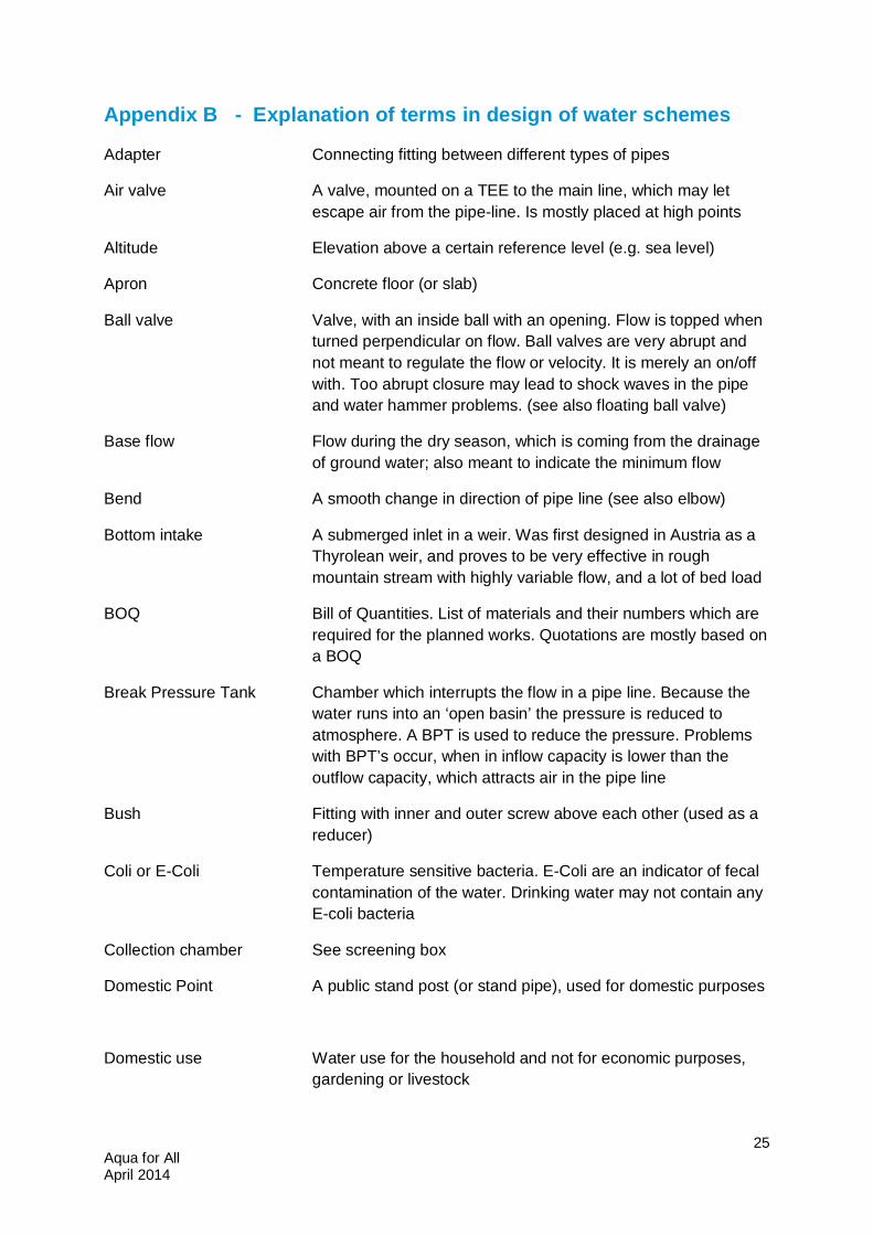
Appendix B - Explanation of terms in design of water schemes
Adapter Connecting fitting between different types of pipes
Air valve A valve, mounted on a TEE to the main line, which may let escape air from the pipe-line. Is mostly placed at high points
Altitude Elevation above a certain reference level (e.g. sea level)
Apron Concrete floor (or slab)
Ball valve Valve, with an inside ball with an opening. Flow is topped when turned perpendicular on flow. Ball valves are very abrupt and not meant to regulate the flow or velocity. It is merely an on/off with. Too abrupt closure may lead to shock waves in the pipe and water hammer problems. (see also floating ball valve)
Base flow Flow during the dry season, which is coming from the drainage of ground water; also meant to indicate the minimum flow
Bend A smooth change in direction of pipe line (see also elbow)
Bottom intake A submerged inlet in a weir. Was first designed in Austria as a Thyrolean weir, and proves to be very effective in rough mountain stream with highly variable flow, and a lot of bed load
BOQ Bill of Quantities. List of materials and their numbers which are required for the planned works. Quotations are mostly based on a BOQ
Break Pressure Tank Chamber which interrupts the flow in a pipe line. Because the water runs into an ‘open basin’ the pressure is reduced to atmosphere. A BPT is used to reduce the pressure. Problems with BPT’s occur, when in inflow capacity is lower than the outflow capacity, which attracts air in the pipe line
Bush Fitting with inner and outer screw above each other (used as a reducer)
Coli or E-Coli Temperature sensitive bacteria. E-Coli are an indicator of fecal contamination of the water. Drinking water may not contain any E-coli bacteria
Collection chamber See screening box
Domestic Point A public stand post (or stand pipe), used for domestic purposes
Domestic use Water use for the household and not for economic purposes, gardening or livestock
Aqua for All April 2014
26
Dynamic grade line A line in a cross section along a pipe line, which represents the pressure when the flow in the pipe line is according to design flow. The line is expressed in meters above a reference level and should stay at least 5 m above the pipe line
Dynamic pressure The pressure in a pipe line (mostly expressed in meter water column above a reference line) when the flow in the pipe line is according to the design capacity (see also residual head and static pressure). Residual head is the dynamic head, expressed as meter water column above the pipe line
Elbow Bend in a pipe with a sharp corner. A bend is smooth. Mind the sharp point of a human elbow
Electrical Conductivity Variable, which is a measure for the salt content of the water. EC is expressed in micro Siemens per cm
Female Terminology, used for fittings, in which other fittings or pipes penetrate (see male)
Flange a circular device, perpendicular on the pipe line, which is meant to join pipes or fittings. Bolds, nuts and gaskets are required to tighten the connection
Floating ball valve Closing device in a water tank, in which the opening and closure of the valve is regulated by a floating ball on the water (as in a toilet). It is not a ball valve
Galvanized Iron (GI) Iron pipes, which are protected against rusting by being ‘galvanized’
Gate valves (or sluice valves); a valve which closes through the movement of a sluice perpendicular on the pipe. Are merely meant to slowly open/close the pipe, but can also be used for flow control
Gravity main The water conduct from the source to the Storage Tank, from where the water is distributed
Gravity scheme A water scheme, where water is not pumped, but only flows because of gravity (the attractive force to earth, which may make things to fall down)
Hardness A chemical expression, which indicates how much carbonate would deposit in case of boiling (kettle stone). It is also a measure for the effectiveness of soap
Hazen Willams Author of a formulae to calculate the friction loss in pipes. To express the roughness of the wall of the pipe, the Hazen William coefficient is used
Aqua for All April 2014
27
HDPE (also “poly” pipe). High density Poly-Ethylene pipe, which is normally black and comes in long rolls. Poly pipe is flexible and not very hard
Hydraulic calculations The calculation of pressure and flow in a water scheme in relation to water consumption and pipe sizes and types. Hydraulic calculations are mostly done to determine the size of the pipes
Hydraulic gradient The decrease of the pressure along a pipe line (as a function of pipe size, flow and altitude)
Hydrostatic water pressure The pressure of water at a certain depth below the water level.
Intake An inlet of raw water (see bottom intake and spring intake)
Karoo A geological period, in which the African and Australian continent broke apart and in which sediments were deposited in a shallow wet environment
Male Terminology, used for fittings which penetrate into other fittings or pipes and have screw on the outside (see female)
Nipple Fitting with two male sides
Nominal Diameter Diameter of reference
Orifice A device in a pipe line to control the flow. The device consists of a ring with a pre-determined central hole. The diameter of the hole defines the maximum flow through the pipe
Overflow Outlet pipe of a tank, which evacuates excessive water and avoids the tank from over flowing through its roof
PE See HDPE
Peak factor A factor, used in hydraulic calculations to determine the maximum required flow in a scheme. The peak factor in the distribution is used to compensate for the uneven distribution of demand during the day. Mostly it is assumed, that people fetch only during 8 or 10 hours water during the day, which correlates with a peak factor of 3 or 2.5 respectively. In the gravity (feeder) mains, mostly a safety factor is used, to compensate for hours of non-service. In Luwuchi a factor 1.4 is used for the first part to the BPT, to enable a higher flow to wash the roughing filters
pH A chemical expression for the acidity of water . pH 7 means neutral; lower is acid and higher is basic
PN Nominal Pressure (normally expressed as 10 m water column)
Poly See HDPE pipe
Aqua for All April 2014
28
PVC Poly-Vinyl Chloride; a plastic, used for many purposes, among which are pipes. When burned, PVC has a very negative environmental impact. PVC pipes are mostly made of recycled PVC
Residual pressure/head The internal pressure in a pipe when water is flowing, expressed as meter water column above the pipe (see also dynamic pressure)
Roughing filter A pre-treatment tank, filled with coarse material (gravels), which is meant to reduce the turbidity of the water to facilitate the real treatment process afterwards
Screening box Chamber which collects raw water from one or more sources and has the function to remove the coarser particles from the water by stilling the water in a ‘basin’ and having a deep storage in which the particles can settle
Slow sand filter A treatment tank, filled with different layers of sand, through which water percolates from the top to the bottom to reduce the level of contamination of the water. The treatment process is most effective in the upper ‘active’ layer
Socket A connector between two pipes, which is wider than the pipe (‘female’); see also spigot
Spigot Plain end of a pipe (‘Male’), which joins to a socket
Static Pressure The pressure in a pipe line in case of absence of flow. The static pressure is mostly expressed in meters water column above the pipe line and is equal to the difference in height between the pipe line and the elevation of the nearest upward tank or intake
Storage Reservoir Tank, used to store water. The purpose of storage is, that it balances between a constant inflow from a source and a highly variable demand from the distribution. Storage is mostly half of the daily consumption
Strainer A device at a pipe inlet, which sieves the coarse materials from the water
Suspended particles Particles that are suspended in the water
TEE Fitting which represents a main pipe and a branch (equal or reducing TEE)
Turbidity Degree of mud content of the water, mostly expressed in Nominal Turbidity Units
Union Fitting of which both sides are female; used to facilitate dismantling of pipes

Aqua for All April 2014
29
Washing Basin One or more slabs meant to do the laundry
Wash Out A device, in which a TEE branches from the main line. The branches has a plug or a valve. When opened, the speed of the water will take all the deposited particles with it. A Wash-out can also be found at the bottom of a tank, where it may drain the dirt, settled at the bottom, if opened
Weir Structure in the water bed to obstruct the flow