hydraulic interface units - coster group - home page€¦ · · 2016-10-044 we resere the right...
TRANSCRIPT
Hydraulic interface units
Electronic Technologies

We reserve the right to make changes without notice.
e-mail: [email protected]
visit: www.coster.eu
“Independent heating” with wall-mounted boilers and hydraulic interface units.
4
Table summarising the advantages of hydraulic interface units against wall mounted boilers.
5
Choosing the correct type of hydraulic interface unit, for maximum and energy efficiency.
7
Recommendations for choosing type of system 8
.1 FAMILIES OF hydrAuLIc IntErFAcE unItS.
utF xxxxx Family of hydraulic interface units. • Fan coils, radiators or panels. • A zone with a temperature equal to that of the risers (climatic or fixed). • Suitable for summer/winter use (cooling/heating). • 3-way zone valve for recirculation with valve closed (not suitable for condensing boilers). • Possibility of distributing and metering hot and cold domestic water.
C BUSC RING
M BUS
14
utF xxxxx Family of hydraulic interface units. • Fan coils, radiators or panels. • A zone with a temperature equal to that of the risers (climatic or fixed). • Suitable for summer/winter use (cooling/heating). • 2-way zone valve without recirculation with valve closed (correct system for condensing boilers). • Possibility of distributing and metering hot and cold domestic water.
C BUSC RING
M BUS
15
uEP xxxxx Family of hydraulic interface units. • Panels.• A summer and winter climatic zone for panels.• Suitable for summer/winter use (cooling/heating).• Fitted with mixing valve and pump.• Possibility of distributing and metering hot and cold domestic water
C BUSC RING
M BUS
16
uEP xxxxx Family of hydraulic interface units. • Panels and bathroom fixtures.• A zone with a temperature equal to that of the risers for bathroom fixture (winter) and
dehumidifier (summer).• A second summer and winter climatic zone for panels.• Suitable for summer/winter use (cooling/heating).• Fitted with mixing valve and pump. • Possibility of distributing and metering hot and cold domestic water
C BUSC RING
M BUS
17
C BUSC RING
RS 232
M BUS
P LOC
Telemanagement

3We reserve the right to make changes without notice.
Hydraulic interfaceunits
.2 AccESSOrIES FOr hydrAuLIc IntErFAcE unItS.
AcP 110 Variable speed circulation pump automation. 20
AcP 120 Apartment energy metering command. 20
AcP 130 Service blocking for users in arrears. 20
AcP 140 Reporting status of summer/winter block of flats signal to apartment.
21
AcP 730 Multipurpose accessory. 21
IPS 438 Variable speed circulation pump automation. 22
SPr 912 Room temperature and dew point sensor. 22
drP 41. Circulation pump regulating unit. 23

4We reserve the right to make changes without notice.
Hydraulic interfaceunits
Hydraulic interface units
The advantages and disadvantages of the three systems are reviewed below from various points of view.A condominium with 30 units is taken as an example, and these may be apartments, offices, commercial busineses, etc.It is assumed that the average maximum heating capacity for the individual units is 7,000 kcal/h.
Definitions.WALL-MOUNTED BOILER• Small gas boiler for each condominium unit (35,000 kcal/h).• Provides heating and domestic hot water.
HYDRAULIc INTERFAcE UNIT• Hydraulic and electrical unit which receives the heat from centralised boiler(s) • Meters the heating for each condominium unit. • Meters the domestic hot water generated centrally.• Meters the domestic cold water for each condominium unit
The answer from a comparative review
“Independent heating” with wall-mounted boilers, or hydraulic interface units?
WALL-MOUNTED BOILERSIn practice, there is no sharing of the costs as the gas bill is paid directly to the supplier.The sharing of the cold water costs may be direct or indirect.
HYDRAULIc INTERFAcE UNITS The sharing is carried out by measuring the energy or other parameters in the individual units and applying the criteria established by the block of flats. These are well-established criteria.
Sharing of the heating, hot water and cold water costs.
The ease of use of the service is absolutely the same for the three systems.
Ease of use of the systems
HYDRAULIc INTERFAcE UNITS✧ 4 inlet pipes (boiler supply and return + cold water + hot water).✧ 4 outlet pipes (2 for heating, 1 for hot
water and 1 for cold water).
WALL-MOUNTED BOILERS✧ 2 inlet pipes (gas + cold water).✧ 3 outlet pipes (2 for heating and 1 for hot water).✧ 1 flue.✧ 1 pipe, if necessary, for outgoing cold water.
Installation
5We reserve the right to make changes without notice.
Hydraulic interfaceunits
wall-mounted boilers
hydraulic interface units notes
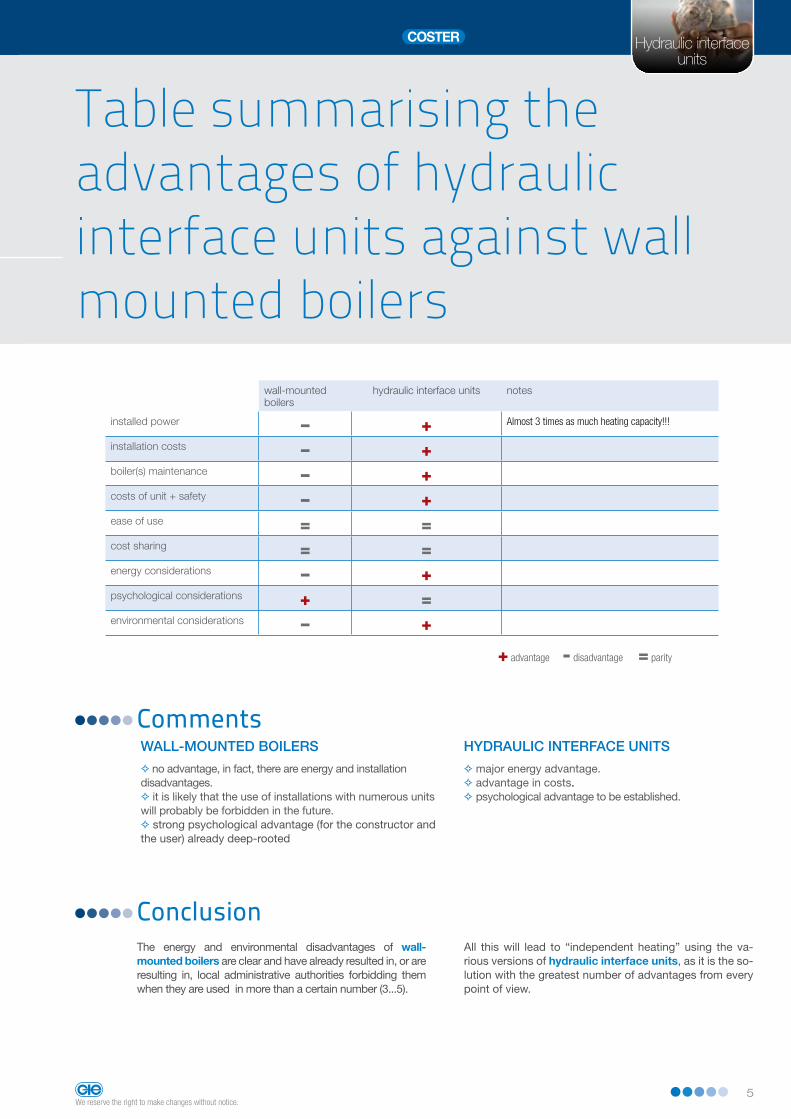
installed power – + Almost 3 times as much heating capacity!!!
installation costs – +boiler(s) maintenance – +costs of unit + safety – +ease of use = =cost sharing = =energy considerations – +psychological considerations + =environmental considerations – +
+ advantage - disadvantage = parity
The energy and environmental disadvantages of wall-mounted boilers are clear and have already resulted in, or are resulting in, local administrative authorities forbidding them when they are used in more than a certain number (3...5).
All this will lead to “independent heating” using the va-rious versions of hydraulic interface units, as it is the so-lution with the greatest number of advantages from every point of view.
Conclusion
CommentsHYDRAULIc INTERFAcE UNITS
✧ major energy advantage.✧ advantage in costs. ✧ psychological advantage to be established.
Hydraulic interface units
Table summarising the advantages of hydraulic interface units against wall mounted boilers
WALL-MOUNTED BOILERS
✧ no advantage, in fact, there are energy and installation disadvantages.✧ it is likely that the use of installations with numerous units will probably be forbidden in the future.✧ strong psychological advantage (for the constructor and the user) already deep-rooted

6We reserve the right to make changes without notice.
Hydraulic interfaceunits
Hydraulic interface units
Comfort and energy saving
Maximum comfort and maximum energy efficiency

7We reserve the right to make changes without notice.
Hydraulic interfaceunits
Once the type of system to be installed in the apartments has been established it is possible to select the simplest type of enclosed control module which satisfies the requi-rements of this system.
The method by which the domestic hot water is distribu-ted or produced significantly influences the selection of the hydraulic interface unit.
Type of system
The best comfort is achieved by supplying the heating appliances, whatever they are with a climatic control tem-perature.
The room thermostats will perform the fine adjustment. Efficiency improves as the regulation of the climatic tem-perature to the heating appliances is improved.
Comfort
The choice of hydraulic interface unit must be made on the basis of:
• Type of system in the apartments;
• Maximum comfort;
• Maximum energy efficiency;
Choosing the correct type of hydraulic interface unit, for maximum comfort and energy efficiency
The energy efficiency refers to the condensing boilers. The system return temperature must be as low as possible.To optimise the condensing efficiency. In order to achieve this, the centralised temperature adjustment must be cli-matic.The climatic temperature adjustment may also be achieved locally, directly in the enclosed control modules.
In order to optimise the comfort or efficiency it is always recommended that the local climatic control is also pre-ceded, whenever possible, by centralised climatic control, calibrated at a slightly higher value.
This facilitates the local adjustment and optimises the sy-stem circulation.
Energy efficiency, climatic adjustment of supply temperature
Hydraulic interface units

8We reserve the right to make changes without notice.
Hydraulic interfaceunits
Hydraulic interface units
Recommendations for choosing type of systemThe type of system to be selected for apartments must consider, whenever possible, the following points:
The use of variable speed pumps a is strongly recommen-ded, automated as best as possible on the basis of the requirements of the various apartments: there is a wide range of possible adjustments.
• Choice for maximum energy efficiency. Systems suitable for the following families of enclosed control modules:
✧ UTF xxxxX. They have centralised production of domestic hot water; they can be supplied with centralised climatic temperature and have 2-way valves.
✧ UEP xxxxX, UEP xxxxX.They have centralised production of domestic hot water, they can be supplied with slightly higher centralised clima-tic temperature and have a local climatic adjustment which is able to better adapt the temperature to the individual apartment or zone. The local climatic adjustment minimises the recirculation into the boiler.
✧ UTF xxxxX.They have 3-way heating valves which circulate all flow back into the boiler when heating is not required. The use of these hydraulic interface units must be reduced to not more than 10-20% of the total when a variable speed system circulation pump, or another type of flow rate automation, is to be used.All the other hydraulic interface units must be fitted with 2-way valves or equivalent.This enables comfort and efficiency to be achieved, even with fixed speed pumps.

9We reserve the right to make changes without notice.
Hydraulic interfaceunits
Recommended family of hydraulic interface units
System with:• Heating, cooling single zone.Radiators, panels or fan coils, single supply temperature.• Domestic hot water with centralised DHW distributed and metered to the users.
This system requires that the apartment is heated with the water at a single temperature, e.g. : a single type of heating appliances.
• Radiators. All the rooms are fitted with radiators designed for the same temperature.
• Panels. All the rooms are heated with floor or ceiling-mounted panels. The bathrooms are fitted with electrical bathroom heating appliances or low temperature bathroom heating appliances with or without electrical integration.
• Fan coils. All the rooms are fitted with fan coils designed for the same temperature. The user may adjust the fan speed to achieve a greater local control, using the built-in thermostat.The enclosed module may be controlled to close the zone valve, when all the fan coils have their own valves closed, using the limit switches of the valves themselves. The climatic control of the supply temperature is centralised and must be calibrated on the type of system.The flow rate may either be adjusted on the number of enclosed modules active at any time, or in climatic mode.
The advantages of this combination are as follows:
• Comfort.The temperature of the heating appliances is always clima-tic or slightly higher, making the temperature perceived by the human body that most suitable for its physiology. The thermal hunting of the heating appliances are eliminated.
• Heating Energy efficiency.The temperature of the water circulating in the heating system is always the lowest, but sufficient at any time, thereby optimising the efficiency of the condensing boilers and minimising the distribution losses.The flow rate adjustment further increases the energy efficiency.
• Domestic hot water energy efficiency. The hot water is produced by a centralised DHW.The DHW temperature may be kept high (70 – 80 °C) and adjusted by means of an electronic mixing device, before being introduced into the distribution network, with recir-culation. The electronic mixing device will be calibrated for the legal requirement of 48 °C.
The DHW may be heated so that the burner operates just a few times a day, at full power to achieve maximum efficiency.
The recommended hydraulic interface unit is of the UTF 5111S, family, which has a two-way zone valve. The 2-way zone valve prevents, with the valve closed, that there is bypass between the system flow and return.
This raises the return temperature considerably, and cen-cels any energy advantage of the condensing boilers. The 3-way valve is not necessary in this type of system, as the system circulation may be automatically balanced by the automatic adjustment of the variable speed pump. In all the enclosed control modules the use of variable speed centralised pumps and an automatic adjustment of the head/flow rate is strongly recommended, for using systems with 2-way zone valves without recirculation, which are harmful for condensing boilers.
UTF xxxxX
Hydraulic interface units

10We reserve the right to make changes without notice.
Hydraulic interfaceunits
With this system the apartment must be heated or air-condi-tioned with water with two temperatures with two supplies.
• Panels. The supply to the panels is adjusted locally with mixer valves and individual circulation pumps. The panels are used for winter heating and summer cooling.
• Radiators Winter radiators (bathrooms) and summer de-humidifiersA second supply arrives in the apartment from the enclosed control module with the temperature equal to that of the heating/cooling plant. Hot water arrives during the winter at climatic temperature suitable for the radiators (bathrooms) which generally have an average temperature. This supply is switched during the summer from the radiators to the dehu-midifiers, to remove humidity from the apartment and allow a better efficiency for the panels without condensation on the floors or ceilings. The centralised winter/summer climatic adjustment of the supply temperature must be calibrated in a slightly excessive manner, to allow the local control to supply the apartment with the best climatic temperature for the comfort. In this way each apartment may have its personalised summer/winter climatic temperature. The flow rate may either be adjusted on the basis of the number of enclosed modules active at any time, or in climatic mode.This type of enclosed module does not generate circulations when it is not active. The local climatic adjustment during the winter is of the conventional type, which may be calibrated for each apartment.The local climatic adjustment during the summer may also be calibrated for each apartment in this case. One or more sen-sors may be installed in one or more rooms of the apartment to continuously monitor the dew point temperatureThe dew point temperature represents the point at which the panels start to produce condensation. This point depends on the temperature and humidity present in the room at that time. The electronic unit of the enclosed control module adjusts the temperature so that it never falls below the condensation level.
The advantages of this system are as follows :
• Comfort. The temperature of the panels is personalised and it is always climatic or slightly higher, making the temperature perceived by the human body that most suitable for its physiology.
• Heating energy efficiency. The temperature of the water circulating in the heating sy-stem is always the lowest, but sufficient at any time, thereby optimising the efficiency of the condensing boilers and minimising the distribution losses. The flow rate adjustment further increases the energy efficiency.
• Air-conditioning energy efficiency.The temperature of the water circulating in the heating system is always the highest, but sufficient at any time, the-reby optimising the efficiency of the cooling equipment and minimising the distribution losses. The flow rate adjustment further increases the energy efficiency .
• Elimination of summer condensation in the panels.During the summer the system sends the correct temperature to the panels for the cooling, but it is never too low, in order to avoid condensation.
• Domestic hot water energy efficiency. The hot water is produced by a centralised DHW. The DHW temperature may be kept high (70 – 80 °C) and adjusted by means of an automatic mixing device, before being introdu-ced into the distribution network, provided with recirculation.The automatic mixing device will be calibrated for the legal requirement of 48 °C.The DHW may be heated so that the burner operates just a few times a day, at full power to achieve maximum efficiency.The centralised climatic adjustment has a summer/winter ca-libration slightly higher than that needed for the apartments.This optimises the temperature and flow rate to the boilers or to the cooling unit.
System with:• 2 zone heating and cooling: one zone with panels and a second zone with radiators.• Domestic hot water with
centralised DHW distributed and metered to the users
Recommended family of hydraulic interface units
UEP xxxxX
Hydraulic interface units

11We reserve the right to make changes without notice.
Hydraulic interfaceunits
Composition of hydraulic interface units
All the distribution and hydraulic interface units consist of the following components::
• Metal enclosure (BXO ......, BXV ......). This consists of a galvanised metal enclosure for embed-ding in the wall, fitted with a frame and a galvanised cover, painted white..
First stage: building works.
• Sub-module plate.This is a plate on which the system’s on-off valves are installed.The plate may be mounted on the bottom of the metal en-closure or, if necessary, fixed to the wall for an “exposed” mounting of the module in a special technological room.Second stage: hydraulic works.
• Distribution and metering module.This includes the hydraulic components, the volume-tric flow meters and the electronic devices for control, adjustment and data processing.
Third stage: final hydraulic and electrical assembly.
The distribution and metering hydraulic hydarulic interface unit may have three basic designs:• horizontal hydraulic interface units with boiler inlets coming from the left,
• horizontal hydraulic interface units with boiler inlets coming from the right, • vertical hydraulic interface units with boiler inlets coming from above.Special designs may be prepared upon request
Metal enclosure Sub-module Distribution and metering module
Complete system
• Horizontal hydraulic interface unit with boiler inlets coming from left.✧ horizontal enclosure BXO xxxxxx✧ sub-module SMF xxxx✧ module UTF xxxxX
• Horizontal hydraulic interface unit with boiler inlets coming from right.✧ horizontal enclosure BXO xxxxxx✧ sub-module SMF xxxx✧ module xxxxX
• Vertical hydraulic interface unit with boiler inlets coming from above.✧ horizontal enclosure BXV xxxxxx✧ sub-module SMF xxxx✧ module UTF xxxxX
Example of distribution and hydraulic interface units
Hydraulic interface units

12We reserve the right to make changes without notice.
Hydraulic interfaceunits

13We reserve the right to make changes without notice.
Hydraulic interfaceunits
Hydraulic interface units• UTF xxxxX;
• UTF xxxxX;
• UEP xxxxX;
• UEP xxxxX;
Tecnologie Elettroniche
Families of hydraulic interface units
14We reserve the right to make changes without notice.
Hydraulic interfaceunits
Heating plant
SUPPLY LINE
Apartment
Hot water Hot water
Wiring connector
Apartment
Cold water Cold water
INCOMING LINE
INCOMING LINE
rEtUrN LINE rEtUrN LINE
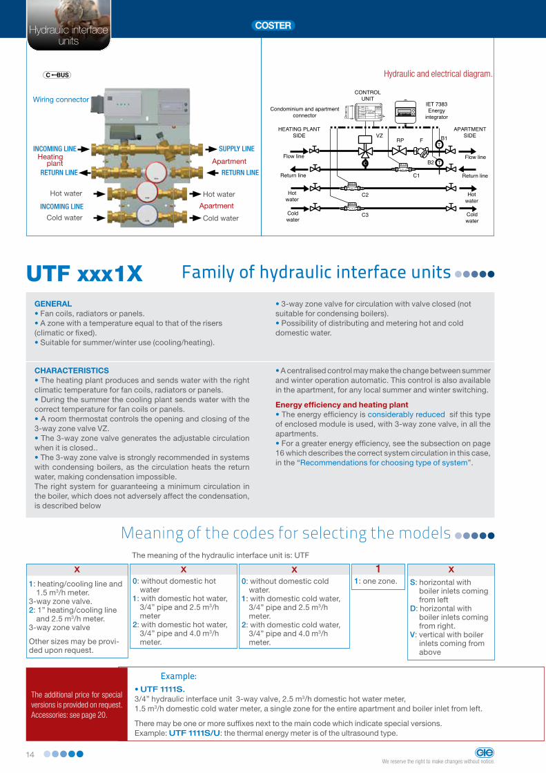
The meaning of the hydraulic interface unit is: UTF
x1: heating/cooling line and
1.5 m3/h meter.3-way zone valve. 2: 1” heating/cooling line
and 2.5 m3/h meter. 3-way zone valve
Other sizes may be provi-ded upon request.
C BUS
SIGLA
C RINGC LOC
Family of hydraulic interface unitsUTF xxx1XGENERAL• Fan coils, radiators or panels.• A zone with a temperature equal to that of the risers (climatic or fixed).• Suitable for summer/winter use (cooling/heating).
• 3-way zone valve for circulation with valve closed (not suitable for condensing boilers).• Possibility of distributing and metering hot and cold domestic water.
CHARACTERISTICS• The heating plant produces and sends water with the right climatic temperature for fan coils, radiators or panels.• During the summer the cooling plant sends water with the correct temperature for fan coils or panels.• A room thermostat controls the opening and closing of the 3-way zone valve VZ.• The 3-way zone valve generates the adjustable circulation when it is closed..• The 3-way zone valve is strongly recommended in systems with condensing boilers, as the circulation heats the return water, making condensation impossible.The right system for guaranteeing a minimum circulation in the boiler, which does not adversely affect the condensation, is described below
• A centralised control may make the change between summer and winter operation automatic. This control is also available in the apartment, for any local summer and winter switching.
Energy efficiency and heating plant • The energy efficiency is considerably reduced sif this type of enclosed module is used, with 3-way zone valve, in all the apartments.• For a greater energy efficiency, see the subsection on page 16 which describes the correct system circulation in this case, in the “Recommendations for choosing type of system”.
Hydraulic interface units
x0: without domestic hot
water1: with domestic hot water,
3/4” pipe and 2.5 m3/h meter
2: with domestic hot water, 3/4” pipe and 4.0 m3/h meter.
x0: without domestic cold
water.1: with domestic cold water,
3/4” pipe and 2.5 m3/h meter.
2: with domestic cold water, 3/4” pipe and 4.0 m3/h meter.
11: one zone.
xS: horizontal with
boiler inlets coming from left
D: horizontal with boiler inlets coming from right.
V: vertical with boiler inlets coming from above
Example:• UTF 1111S. 3/4” hydraulic interface unit 3-way valve, 2.5 m3/h domestic hot water meter,1.5 m3/h domestic cold water meter, a single zone for the entire apartment and boiler inlet from left.
There may be one or more suffixes next to the main code which indicate special versions.Example: UTF 1111S/U: the thermal energy meter is of the ultrasound type.
The additional price for special versions is provided on request. Accessories: see page 20.
Meaning of the codes for selecting the models
Hydraulic and electrical diagram.
TB1
TB2
C2
C3
C1
VZ
NO
SIAPERTURA FORZATA
VALVOLA
10
9
8
7
6
5
4
3
2
1
Tm
Tm
A+
A0
P
P
0C
C
N
L
COMANDOPOMPA
ALLARME
TERMOSTATO(contatto chiuso= valvola aperta)
ZONA:
UTENTE:
INDIRIZZO C-BUS:
0C BUS
N
L230 V ~
RETE VALVOLA
CASSETTA DICONTABILIZZAZIONE
COSTER
RP F
Condominium and apartment connector
APARTMENT SIDE
Flow line
Return line
Hotwater
Coldwater
Flow line
Return line
Hotwater
Coldwater
CONTROLUNIT
IET 7383Energy
integrator

15We reserve the right to make changes without notice.
Hydraulic interfaceunits
Hydraulic interface units
Heating plant
SUPPLY LINE
Apartment
Hot water Hot water
Wiring connector
Cold water Cold water
INCOMING LINE
INCOMING LINE
rEtUrN LINE rEtUrN LINE
C BUS
SIGLA
C RINGC LOC
Family of hydraulic interface unitsUTF xxx1XGENERAL• Fan coils, radiators or panels.• A zone with a temperature equal to that of the risers (climatic or fixed).• Suitable for summer/winter use (cooling/heating).
• 2-way zone valve without circulation with valve closed (correct system for condensing boilers).• Possibility of distributing and metering hot and cold domestic water
CHARACTERISTICS • The heating plant produces and sends water with the right climatic temperature for fan coils, radiators or panels.• During the summer the cooling plant sends water with the correct temperature for fan coils or panels.• A room thermostat controls the opening and closing of the 2-way zone valve VZ.• The 2-way zone valve does not generate the circulation when it is closed..• The 2-way zone valve is strongly recommended in systems with condensing boilers, as it does not generate circulation between system supply and return, when it is closed. • When the use of this type of enclosed module is planned, without circulation with zone valve closed, the use of automa-tion is strongly recommended, to control the system variable speed circulation pump. It is necessary to guarantee a minimum circulation when all the users are closed, and an ever-increasing circulation as the number of active users is increased.
• A centralised control may make the change between summer and winter operation automatic. This control is also available in the apartment, for any local summer and winter switching.
Energy efficiency and heating plant. • The energy efficiency is the greatest with the use of this type of hydraulic interface unit and with the correct control of the system circulation.
The meaning of the hydraulic interface unit code is: UTF
x5: 3/4” heating/cooling
line and 1.5 m3/h meter. 2-way zone valve.
6: 1” heating/cooling line and 2.5 m3/h meter 2-way zone valve.
Other sizes may be provi-ded upon request..
x0: without domestic hot
water.1: with domestic hot water,
3/4” pipe and 2.5 m3/h meter.
2: with domestic hot water, 3/4” pipe and 4.0 m3/h meter.
x0: without domestic cold
water.1: with domestic cold wa-
ter, 3/4” pipe and 2.5 m3/h meter.
2: with domestic cold water, 3/4” pipe and 4.0 m3/h meter.
11: one zone.
xS: horizontal with
boiler inlets coming from left..
D: horizontal with boiler inlets coming from right.
V: vertical with boiler inlets coming from above
Examples:• UTF 5111S. 3/4” hydraulic interface unit 2-way valve, 2.5 m3/h domestic hot water meter, 4.0 m3/h domestic cold water meter, a single zone for the entire apartment and boiler inlet from left..
There may be one or more suffixes next to the main code which indicate special versions.Example: UTF 5111S/U: the thermal energy meter is of the ultrasound type
Hydraulic and electrical diagram.
The additional price for special versions is provided on request. Accessories: see page 20.
Meaning of the codes for selecting the models
APARTMENT
Flow line
Return line
Flow line
Return line
IET 7383Energy integrator
TB1
TB2
C2
C3
C1
VZ
NO
SIAPERTURA FORZATA
VALVOLA
10
9
8
7
6
5
4
3
2
1
Tm
Tm
A+
A0
P
P
0C
C
N
L
COMANDOPOMPA
ALLARME
TERMOSTATO(contatto chiuso= valvola aperta)
ZONA:
UTENTE:
INDIRIZZO C-BUS:
0C BUS
N
L230 V ~
RETE VALVOLA
CASSETTA DICONTABILIZZAZIONE
COSTER
RP F
Condominium and apartment connector
HEATING PLANTSIDE
APARTMENT SIDE
CONTROLUNIT
Hotwater
Coldwater
Hotwater
Coldwater
16We reserve the right to make changes without notice.
Hydraulic interfaceunits
Heating plant
rEtUrN LINE
INCOMING LINE
INCOMING LINE APARTAMENT
SUPPLY LINE
rEtUrN LINEPanels
Hot water Hot water
Cold waterCold Water
Wiring connector
Meaning of the codes for selecting the models
C BUS
SIGLA
C RINGC LOC
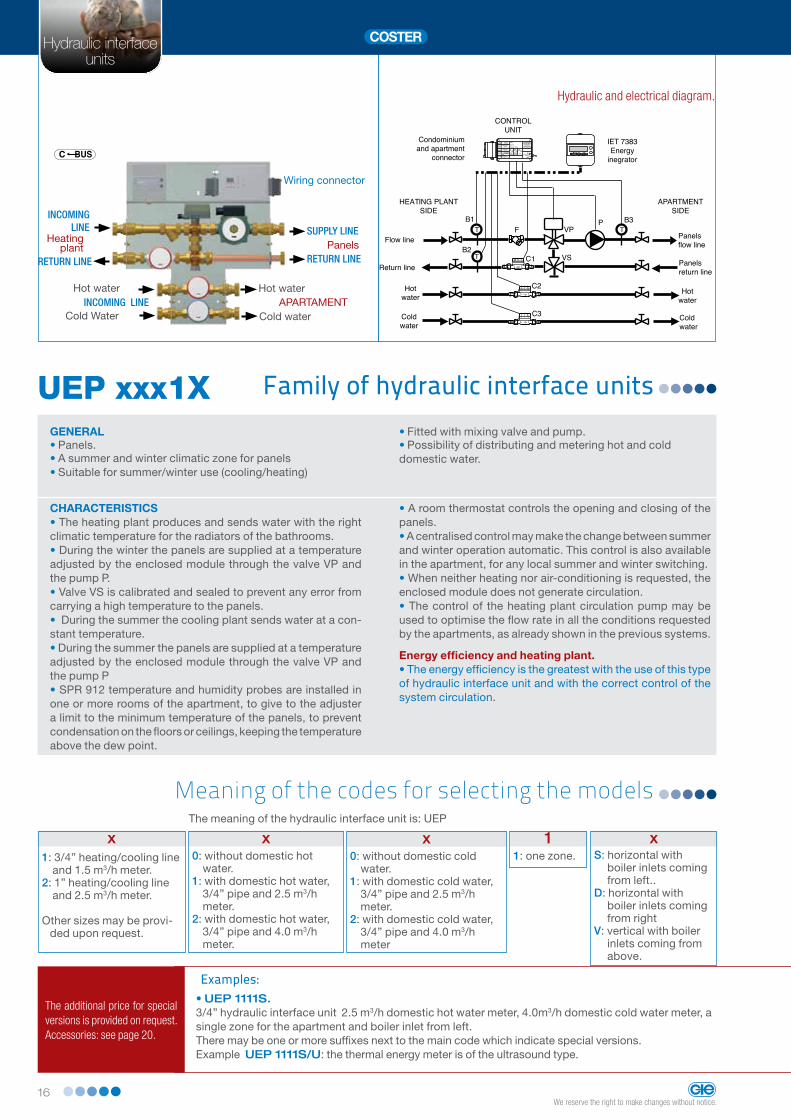
Family of hydraulic interface unitsUEP xxx1XGENERAL• Panels.• A summer and winter climatic zone for panels• Suitable for summer/winter use (cooling/heating)
• Fitted with mixing valve and pump.• Possibility of distributing and metering hot and cold domestic water.
CHARACTERISTICS• The heating plant produces and sends water with the right climatic temperature for the radiators of the bathrooms.• During the winter the panels are supplied at a temperature adjusted by the enclosed module through the valve VP and the pump P.• Valve VS is calibrated and sealed to prevent any error from carrying a high temperature to the panels.• During the summer the cooling plant sends water at a con-stant temperature.• During the summer the panels are supplied at a temperature adjusted by the enclosed module through the valve VP and the pump P• SPR 912 temperature and humidity probes are installed in one or more rooms of the apartment, to give to the adjuster a limit to the minimum temperature of the panels, to prevent condensation on the floors or ceilings, keeping the temperature above the dew point.
• A room thermostat controls the opening and closing of the panels.• A centralised control may make the change between summer and winter operation automatic. This control is also available in the apartment, for any local summer and winter switching.• When neither heating nor air-conditioning is requested, the enclosed module does not generate circulation.• The control of the heating plant circulation pump may be used to optimise the flow rate in all the conditions requested by the apartments, as already shown in the previous systems.
Energy efficiency and heating plant. • The energy efficiency is the greatest with the use of this type of hydraulic interface unit and with the correct control of the system circulation.
The meaning of the hydraulic interface unit is: UEP
x1: 3/4” heating/cooling line
and 1.5 m3/h meter. 2: 1” heating/cooling line
and 2.5 m3/h meter.
Other sizes may be provi-ded upon request.
x0: without domestic hot
water.1: with domestic hot water,
3/4” pipe and 2.5 m3/h meter.
2: with domestic hot water, 3/4” pipe and 4.0 m3/h meter.
x0: without domestic cold
water.1: with domestic cold water,
3/4” pipe and 2.5 m3/h meter.
2: with domestic cold water, 3/4” pipe and 4.0 m3/h meter
11: one zone.
xS: horizontal with
boiler inlets coming from left..
D: horizontal with boiler inlets coming from right
V: vertical with boiler inlets coming from above.
Examples:• UEP 1111S. 3/4” hydraulic interface unit 2.5 m3/h domestic hot water meter, 4.0m3/h domestic cold water meter, a single zone for the apartment and boiler inlet from left.There may be one or more suffixes next to the main code which indicate special versions.Example UEP 1111S/U: the thermal energy meter is of the ultrasound type.
The additional price for special versions is provided on request.Accessories: see page 20.
Hydraulic and electrical diagram.
Hydraulic interface units
T
T
TB1
B2
B3PVP
C2
C3
C1
NO
SIAPERTURA FORZATA
VALVOLA
10
9
8
7
6
5
4
3
2
1
Tm2
Tm2
0V
0..5V
0C
C
N
L
Comando climatico
bassa temp.
TERMOSTATO 1Radiatori
(chiuso = valvola aperta)
ZONA:
UTENTE:
INDIRIZZO C-BUS:
0C BUS
N
L230 V ~
APERTABASSA
TEMPER.
CASSETTA DICONTABILIZZAZIONE2 ZONE 2 TEMPERAT.
COSTER
RETEAPERTA
ALTATEMPER.
TERMOSTATO 2Pannelli
(chiuso = valvola aperta)
Tm1
Tm1
Condominium and apartment
connector
CONTROLUNIT
HEATING PLANTSIDE
Flow line
Return line
Hotwater
Coldwater
Panelsflow line
Panelsreturn line
Hot water
Coldwater
APARTMENT SIDE
F
VS
IET 7383Energy
inegrator

17We reserve the right to make changes without notice.
Hydraulic interfaceunits
Hydraulic interface units
Heating plant
rEtUrN LINE
INCOMING LINE
SUPPLY LINERadiator
rEtUrN LINEPanels
SUPPLY LINEPanels
rEtUrN LINERadiators
Hot water
Cold waterINCOMING LINE
Hot water
Cold water
Wiring connector
Meaning of the codes for selecting the models
C BUS
SIGLA
C RINGC LOC
Family of hydraulic interface unitsUEP xxx2XGENERAL• Panels and bathroom fixtures • A zone with a temperature equal to that of the risers for bathroom fixture (winter) or dehumidifier (summer). • A second summer and winter climatic zone for panels.• Suitable for summer/winter use (cooling/heating).
• Fitted with mixing valve and pump.• Possibility of distributing and metering hot and cold domestic water.
CHARACTERISTICS• The heating plant produces and sends water with the right climatic temperature for the radiators of the bathrooms• During the winter the panels are supplied at a temperature regulated by the enclosed module by means of the valve VP and the pump P.• Valve VS is calibrated and sealed to prevent any error from carrying a high temperature to the panels.• During the summer the cooling plant sends water with the correct temperature for any dehumidifiers• During the summer the panels are supplied at a temperature adjusted by the enclosed module by means of the valve VP and the pump P.• SPR 912, temperature and humidity probes are installed in one or more rooms of the apartment, to give to the adjuster a limit to the minimum temperature of the panels, to prevent condensation on the floors or ceilings, keeping the temperature above the dew point.
• Two room thermostats control the opening and closing of the panels and the radiators (bathrooms)
• A centralised control may make the change between summer and winter operation automatic. This control is also available in the apartment, for any local summer and winter switching (e.g. summer dehumidifier control).• When neither heating nor air-conditioning is requested, the enclosed module does not generate circulation• The control of the heating plant circulation pump may be used to optimise the flow rate in all the conditions requested by the apartments, as already shown in the previous systems.
Energy efficiency and heating plant. • The energy efficiency is the greatest with the use of this type of hydraulic interface unit and with the correct control of the system circulation.
The meaning of the hydraulic interface unit is: UEP
x1: 3/4” heating/cooling line
and 1.5 m3/h meter.. 2: 1” heating/cooling line
and 2.5 m3/h meter..
Other sizes may be provi-ded upon request
x0: without domestic hot
water.1: with domestic hot water,
3/4” pipe and 2.5 m3/h meter
2: with domestic hot water, 3/4” pipe and 4.0 m3/h meter.
x0: without domestic cold
water.1: with domestic cold water,
3/4” pipe and 2.5 m3/h meter..
2: with domestic cold water, 3/4” pipe and 4.0 m3/h meter.
22: two zones.
xS: horizontal with
boiler inlets coming from left.
D: horizontal with boiler inlets coming from right.
V: vertical with boiler inlets coming from above.
The additional price for special versions is provided on request.Accessories: see page 20.Contact the sales network to check availability and delivery times.
Hydraulic and electrical diagram.
Example• UEP 1112S. 3/4” hydraulic interface unit 2.5 m3/h domestic hot water meter, 4.0m3/h domestic cold water meter, two zones for the apartment and boiler inlet from left .There may be one or more suffixes next to the main code which indicate special versions..Example: UEP 1112S/U: the thermal energy meter is of the ultrasound type.
APARTMENT
T
T
TB1
B2
B3PVP
VR
C2
C3
C1
NO
SIAPERTURA FORZATA
VALVOLA
10
9
8
7
6
5
4
3
2
1
Tm2
Tm2
0V
0..5V
0C
C
N
L
Comando climatico
bassa temp.
TERMOSTATO 1Radiatori
(chiuso = valvola aperta)
ZONA:
UTENTE:
INDIRIZZO C-BUS:
0C BUS
N
L230 V ~
APERTABASSA
TEMPER.
CASSETTA DICONTABILIZZAZIONE2 ZONE 2 TEMPERAT.
COSTER
RETEAPERTA
ALTATEMPER.
TERMOSTATO 2Pannelli
(chiuso = valvola aperta)
Tm1
Tm1
Condominium and apartment connector
CONTROLUNIT
HEATING PLANTSIDE
Flow line
Return line
Hotwater
Coldwater
Radiators flow line
(bathrooms)
Panelsflow line
Panels return line
Radiators return line (bathrooms)
Hotwater
Coldwater
APARTMENT SIDE
F
VS
IET 7383Energy integrator

18We reserve the right to make changes without notice.
Hydraulic interfaceunits
Hydraulic interface units
Accessories for hydraulic interface units

19We reserve the right to make changes without notice.
Hydraulic interfaceunits
Tecnologie Elettroniche
Accessories for hydraulic interface units
All the units are fitted with a C-Bus communication line for local centralised readout or remote readout by remote management.They can also be completed with accessories which, with additional functions, allow the comfort and the energy efficiency of the system to be optimised.The main functions which can be performed with the ac-cessories are as follows:
• Intelligent automation of the variable speed circulation pump of the primary circuit (boiler/cooler circuit).An accessory, inserted in every hydraulic interface unit signals to a central unit whether the enclosed module is “active” (that is, whether it requests hot/cold). By knowing the number of apartments which request the service and, therefore, the instantaneous heating/cooling requirements, the operation of the variable speed circulation pump for the heating plant may be optimised
• Providing the user with the possibility of controlling the consumption of heat/cool.A meter installed in the apartment receives the pulses from an accessory inserted in the hydraulic interface unit displaying the energy consumption of the apartment.
• Stopping heating/cooling for users with unpaid service billsThis function is made available by inserting an accessory in the hydraulic interface unit and may only be activated by remote management.
• Signalling to the apartment the status of the condomi-nium winter/summer controls.An accessory installed in the hydraulic interface unit provides the apartment with a dry contact which may be:• The summer/winter condominium command may be transferred to the apartment in the form of a dry contact, and be used, for example✧ insertion of radiators (bathroom fixture) in the winter;✧ insertion of a de-humidifier in the summer;✧ switching of the thermostat function

20We reserve the right to make changes without notice.
Hydraulic interfaceunits
GENERALAccessory cable to be inserted in the hydraulic interface unit unit by means of an RJ 6 pole connector.The auxiliary output of the IET 73.3 integrator/me-tering device, programmed on “energy+remote control”, launches a pulse in kWh.
The ACP 120 accessory receives the pulses from the integrator and transfers them, in the form of open/closed contact, to the UCI 120 meter installed in the apartment.This allows the user to know the quantity of energy consumed
code description Data sheet
ACP 120 Energy meter control H 890
Apartment energy metering commandACP 120
code description Data sheet
ACP 130 Accessory cable for blocking service to users in arrears H 890
GENERALAccessory cable to be inserted in the hydrau-lic interface unit or by means of an RJ 6 pole connector. The ACP 130 accessory allows the heating/cooling to be locked for users with unpaid service bills.
The lock may only be activated by remote control.The service for the supply of domestic hot and cold water, which is considered to be essential, is not locked.
Service blocking for users in arrearsACP 130
Variable speed circulation pump automation
ACP 110
GENERALAccessory cable to be inserted in every hydrau-lic interface units by means of an RJ 6 pole connector.Connected in parallel with the ACP 110 of all the other enclosed modules or satellite units, is carried to the heating plant and connected to the IPS 438 unit.This unit, after determining the instantaneous thermal head of the system, controls the speed
of the variable speed circulation pump and commands the opening of the bypass which allows an adequate circulation when the number of “active” hydraulic interface unit falls below the minimum established value.The hydraulic interface units with 3-way valves can therefore be completely eliminated, as the pump has a minimum guaranteed circulation and is only switched off when no hydraulic interface unit is “active”
code description Data sheet
ACP 110 Accessory cable for automation of hydraulic interface units H 890
21We reserve the right to make changes without notice.
Hydraulic interfaceunits
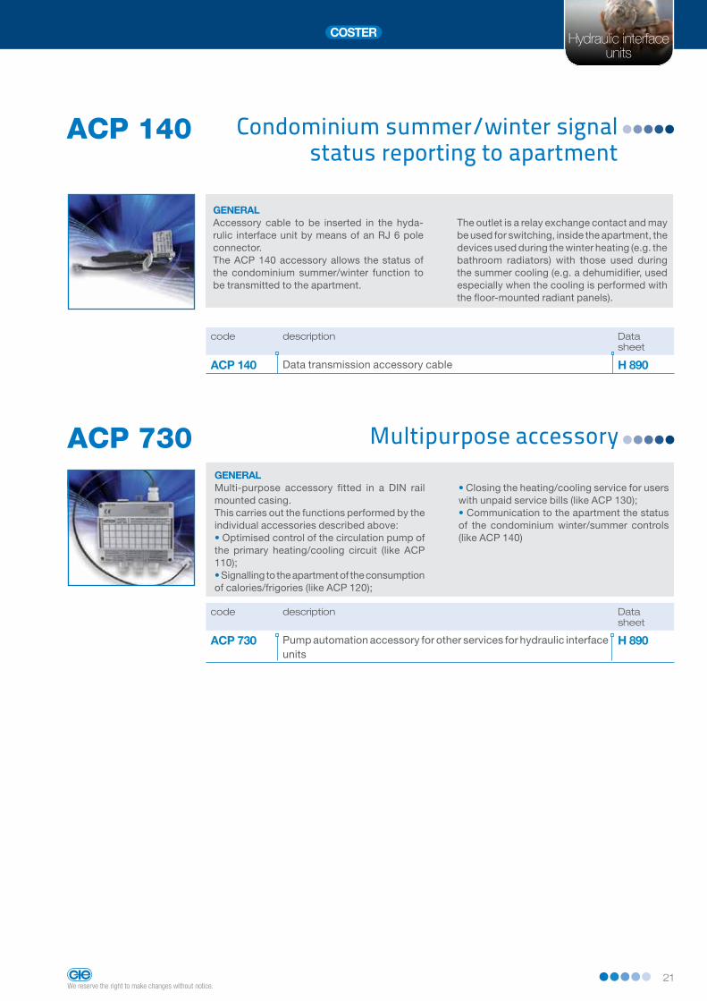
Multipurpose accessoryACP 730GENERALMulti-purpose accessory fitted in a DIN rail mounted casing.This carries out the functions performed by the individual accessories described above:• Optimised control of the circulation pump of the primary heating/cooling circuit (like ACP 110);• Signalling to the apartment of the consumption of calories/frigories (like ACP 120);
• Closing the heating/cooling service for users with unpaid service bills (like ACP 130);• Communication to the apartment the status of the condominium winter/summer controls (like ACP 140)
code description Data sheet
ACP 730 Pump automation accessory for other services for hydraulic interface units
H 890
code description Data sheet
ACP 140 Data transmission accessory cable H 890
Condominium summer/winter signal status reporting to apartment
ACP 140
GENERALAccessory cable to be inserted in the hyda-rulic interface unit by means of an RJ 6 pole connector. The ACP 140 accessory allows the status of the condominium summer/winter function to be transmitted to the apartment.
The outlet is a relay exchange contact and may be used for switching, inside the apartment, the devices used during the winter heating (e.g. the bathroom radiators) with those used during the summer cooling (e.g. a dehumidifier, used especially when the cooling is performed with the floor-mounted radiant panels).

22We reserve the right to make changes without notice.
Hydraulic interfaceunits
Variable speed circulation pump automation
IPS 438
GENERALThe hydraulic interface units must be provided with the ACP 110 or ACP 730 accessory.The IPS 438 unit collects all the data and knows, in real time, the number of “active” hydraulic interface units.Depending on the number determined it acts as follows:• Switches off the pump of the primary heating/cooling circuit when no hydraulic interface unit is “active”.This function is very useful especially in the period between the winter and summer months, when the request for heat (in the winter) or co-oling (in the summer) may be zero.• Switches off the heating plant or forces it into frost protection mode when no hydraulic interface unit is “active”.
• Opens a bypass to guarantee a minimum circulation in the primary system when the number of “active” hydraulic interface unit is less than 3 elements.In this way, all the hydraulic interface units with 2-way zone valves (without circulation with valve closed) can be used to favour the use of condensing boilers.• Control of speed of variable speed circulation pump.The speed is proportional to the number of hydraulic interface units “active” at any time, so the flow rate is optimised on the basis of the request, thereby guaranteeing greater comfort and energy efficiency.
CHARACTERISTICS • Power Supply: 230 Volt~;• Consumption: 2 VA;
• Modular enclosure DIN 71x116;• Protection rating: IP 40.
code description Data sheet
IPS 438 Circulation pump automation unit in systems with hydraulic interface units
H 890
Room temperature and dew point sensorSPR 912
GENERALIn all the hydraulic interface units which include a climatic temperature regulator for floor-mounted radiant panels, it is essential that one or more dew point sensors are installed in the apartment during the summer cooling period.
The climatic regulator will ensure that the tem-perature of the floor-mounted radiant panels does not fall below the dew point value, thereby ensuring that condensation does not form on the radiant surfaces.
code description Data sheet
SPR 912 Room temperature and dew point sensor N 610
CHARACTERISTICS• Power Supply: 12 Volt~ from the hydraulic interface unit

23We reserve the right to make changes without notice.
Hydraulic interfaceunits
Circulation pump regulating unitDRP 41...GENERAL• Control: ✧ modulating with 3 points or progressive 0...10 V;or ✧ modulating with 3 points with in sequence
the progressive no
• Programming with 4 operational keys and alphanumeric display.
CHARACTERISTICS• It is possible to control and regulate: ✧ one or two variable speed pumps; ✧ a fixed speed pump + a variable speed
pump; ✧ two fixed speed pumps; ✧ a fixed speed pump + a bypass valve; ✧ a variable speed pump + a bypass valve.
TECHNICAL DATA• Power supply:: ✧ DRP 418: 230V AC ±10% 50...60Hz; ✧ DRP 414: 24 V AC.• Power consumption: 3VA.• Capacity of contacts without voltage:
250V AC, 5(1)A.• Mounted on DIN.• Protection: IP 40.• Analogue inputs: ✧ 1 x head sensor 0...10 Volt;; ✧ 1 of 0...10 Volt from outside x head nee-
ded by system• Communication systems: ✧ C-Bus for remote management
code description Data sheet
DPR 418 230 VAC Circulation pump regulating unit D 413
DPR 414 24 VAC Circulation pump regulating unit D 413
C BUS
RS 232
C RING
M BUS
SENSORS NECESSARY• 1 for differential pressure;• 1 for hydraulic pressure
code description measurementrange
maximumpressure
Datasheet
SPW 204 Liquids pressure sensor 0...4 bar 8 bar N 412
SPW 210 Liquids pressure sensor 0...10 bar 20 bar N 412
SPW 216 Liquids pressure sensor 0...16 bar 32 bar N 412
SDW 201 Liquids differential pressure sensor 0...1 bar 6 bar N 422
SDW 202 Liquids differential pressure sensor 0...2,5 bar 6 bar N 422
SDW 206 Liquids differential pressure sensor 0...6 bar 16 bar N 422
SENSORS AND ACCESSORIES

Head Office and Salesvia San G.B. De La Salle, 4/a 20132 MilanoTel. +39 02 2722121 Fax +39 02 [email protected] [email protected]
Branch in UK.COSTER T.E. UK BRANCH
5 Shaftesbury Street South, Sir Francis Ley Industrial Park - Derby DE23 8YH
Tel. +44 (0) 1332 200555 Fax +44 (0) 1332 204181
COSTER TECNOLOGIE ELETTRONICHE S.p.A.
ww
w.c
os
te
r.e
u
2014
ver
sion
00
D31
110
agen
ziaz
elas
chi.i
t
COSTERmade in Italy