hydraulic nuts hydnut..-e - · pdf filest4_9007213134647435_hydraulik.fm seite 7 montag, 20....
TRANSCRIPT
Hydraulic NutsHYDNUT..-E, HYDNUT..-E-INCH
User manual

Foreword
New designation The new hydraulic nuts can be identified from the -E inthe designation. The E stands for Enhanced and this means that some improvements have been made.
Measuringthe drive-up distance
At first sight, it is not possible to identify the new piston form,but it is precisely this characteristic that gives a major advantage: the drive-up distance can be measured simply using a conventional dial gauge. This is fitted in the hole for the dial gauge and is located by hand using a knurled clamping screw made from plastic.The tip of the measuring pin lies flat on the new collar of the piston, which means that the stroke can be measured precisely.
Marking The marking is also a new feature. Each hydraulic nut is markedwith the maximum permissible pressure and the thread present.This facilitates reliable operation and damage-free mounting.
Mounting and dismounting Mounting and dismounting is aided by the hand lever now supplied. This is inserted in a handling hole and, as a result, the hydraulic nut can be easily screwed and unscrewed.If maintenance or repair becomes necessary at any time, the new dismounting screws made from corrosion-resistant steel give considerable benefit in dismounting. The annular piston can thusbe unscrewed uniformly from the press ring.The maximum stroke is indicated by a red O ring, thus reliably preventing excessive outward movement of the piston and allthe resulting consequences. Simple visual inspection is sufficient during use.
Current version A current version of this user manual can be found at http://medien.schaeffler.com using the search term BA4.
2 BA 04 Schaeffler Technologies
Page
Contents
About the user manual Symbols ................................................................................... 4
Availability................................................................................ 4
Legal guidelines........................................................................ 4
Original user manual................................................................. 4
Generalsafety guidelines
Usage for the intended purpose ................................................ 5
Usage not for the intended purpose........................................... 5
Qualified personnel .................................................................. 5
Hazards .................................................................................... 5
Protective equipment ................................................................ 5
Safety regulations ..................................................................... 6
Scope of delivery ................................................................................................. 7
Accessories .............................................................................. 8
Further information ................................................................... 8
Damage during transit............................................................... 8
Defects ..................................................................................... 8
Description Press ring.................................................................................. 9
Annular piston .......................................................................... 9
Sealing rings............................................................................. 9
Red O ring................................................................................. 9
Press ring.................................................................................. 10
Annular piston .......................................................................... 14
Other components .................................................................... 15
Function ................................................................................... 17
Commissioning Checking the hydraulic nut ........................................................ 20
Lifting the hydraulic nut out of the transport container and transporting the hydraulic nut ................................................... 21
Preparation for mounting .......................................................... 23
Mounting the hydraulic nut ....................................................... 25

Schaeffler Technologies BA 04 3
PageApplying the mounting ring ....................................................... 32
Applying the intermediate ring .................................................. 33
Selecting and mounting the dial gauge...................................... 34
Selecting the pressure generation device .................................. 37
Operation Drive-up distance ..................................................................... 38
Hydraulic oil ............................................................................. 38
Maximum pressure ................................................................... 39
Mounting the hydraulic hose..................................................... 40
Bleeding................................................................................... 42
Pressing the component into place ........................................... 44
Pressing back the annular pistonHYDNUT50-E to HYDNUT190-E................................................... 47
Pressing back the annular pistonHYDNUT200-E to HYDNUT1180-E............................................... 48
Decommissioning Storage .................................................................................... 54
Troubleshooting ................................................................................................ 55
Maintenance Maintenance plan..................................................................... 56
Ordering the seal ...................................................................... 56
Replacing the seal .................................................................... 56
Dismounting the annular piston ................................................ 57
Dismounting the seals .............................................................. 58
Cleaning the components ......................................................... 59
Mounting the seals ................................................................... 60
Mounting the annular piston..................................................... 61
Disposal Regulations .............................................................................. 63
Technical data, accessoriesand replacement parts
................................................................................................ 64
Appendix EC Declaration of Conformity..................................................... 65
4 BA 04 Schaeffler Technologies
Hydraulic nuts HYD-NUT..-E, HYDNUT..-E-INCH
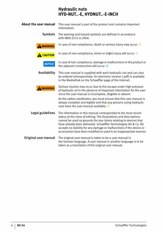
About the user manual This user manual is part of the product and contains important information.
Symbols The warning and hazard symbols are defined in accordancewith ANSI Z535.6-2006.
WARNING In case of non-compliance, death or serious injury may occur.
CAUTION In case of non-compliance, minor or slight injury will occur.
NOTICE In case of non-compliance, damage or malfunctions in the product or the adjacent construction will occur.
Availability This user manual is supplied with each hydraulic nut and can alsobe ordered retrospectively. An electronic version (.pdf) is availablein the Mediathek on the Schaeffler page of the Internet.
WARNING Serious injuries may occur due to the escape under high pressureof hydraulic oil in the absence of important information for the user since the user manual is incomplete, illegible or absent.As the safety coordinator, you must ensure that this user manual is always complete and legible and that any persons using hydraulic nuts have the user manual available.
Legal guidelines The information in this manual corresponded to the most recent status at the close of editing. The illustrations and descriptions cannot be used as grounds for any claims relating to devices that have already been delivered. Schaeffler Technologies AG & Co. KG accepts no liability for any damage or malfunctions if the device or accessories have been modified or used in an inappropriate manner.
Original user manual The original user manual is taken to be a user manual inthe German language. A user manual in another language is to be taken as a translation of the original user manual.

Schaeffler Technologies BA 04 5
General safety guidelines It describes how the hydraulic nut may be used, who may usethe hydraulic nut and what must be observed in general during its use.
Usagefor the intended purpose
In the case of hydraulic nuts, usage for the intended purpose comprises the mounting and dismounting of rolling bearingsas well as the mounting and loosening of press fits such as ships’ propellers and rubber blades, shaft couplings and gears.
Usage notfor the intended purpose
The hydraulic nut must not be used to lift loads. Unilateral loadingis not possible, instead load must be applied uniformly overthe circumference of the annular piston.Usage not for the intended purpose can lead to injury or damage.
Qualified personnel The hydraulic nut must only be used by suitably qualified personnel.A person defined as qualified personnel:■ has all the necessary knowledge■ has been trained in working on rolling bearings and hydraulic
tools■ is aware of all the hazards and safety guidelines■ is authorised to use a hydraulic nut by the safety co-ordinator■ has fully read and understood this user manual.
Hazards If a hydraulic nut is damaged, hydraulic oil may be sprayed out under high pressure. For this reason, only an undamaged hydraulic nut may be used and repairs to the hydraulic nut are therefore prohibited.
Protective equipment Personal protective equipment is intended to protect operating personnel against health hazards. This comprises safety goggles, safety shoes and gloves and these must be used in the interestsof personal safety.
6 BA 04 Schaeffler Technologies
Hydraulic nuts HYD-NUT..-E, HYDNUT..-E-INCH
Safety regulations The following safety specifications must be observed when working with the hydraulic nut. Further guidelines on hazards and specific operating procedures can be found, for example, in the descriptions of the operation of hydraulic nuts, see page 38.Safety specifications for the pressure generation device can be found in the user manual of the pressure generation device.
Transport If the ambient conditions during transport differ to a large extent from the ambient conditions specified for its operation, usage ofthe hydraulic nut must be stopped immediately.The hydraulic nut must always be stored and operated underthe ambient conditions described. Before storage, preservative must be applied to the hydraulic nut in order to give protection against corrosion.Unsuitable ambient conditions can endanger the health ofthe operating personnel.The hydraulic nut must not be operated at a pressure greater than the maximum permissible operating pressure.These ambient conditions are as follows:■ humidity max. 65%, non-condensing■ no aggressive chemicals in the environment■ temperature from +5 °C to +40 °C■ clean environment.
Maintenance The hydraulic nut must undergo regular maintenance, see page 56.Only original replacement parts may be used.
Conversion The hydraulic nut must not be converted.

Schaeffler Technologies BA 04 7
Scope of delivery The scope of delivery comprises the hydraulic nut, accessories and user manual, see table and Figure 1.
Hydraulic nut HYDNUT
1) Allocation, see tables, page 12.2) Allocation, see tables, page 11.
Component Designation Quan-tity
Hydraulic nut HYDNUT 1
Clamping screw – 3
Screw plug (G1/4) HYDNUT.PLUG 2
Dismounting screw1) – 35
Valve nipple (G1/4) PUMP1000.VALVE-NIPPLE 1
Hand lever2) HYDNUT-HANDHEBEL-D10.PRT 1
HYDNUT-HANDHEBEL-D12.PRT 1
HYDNUT-HANDHEBEL-D16.PRT 1
Seal set(replacement outer seal, replacement inner seal andred O ring)
HYDNUT...SEAL 1
User manual – 1
� Hydraulic nut� Clamping screws
� Screw plug� Dismounting screws
� Hand lever� Valve nipple
� Replacement seals for outer side,inner side and red O ring
User manual
Figure 1Scope of delivery
HYDNUT...-E(-INCH) 000B
0603
000B
0603

8 BA 04 Schaeffler Technologies
Hydraulic nuts HYD-NUT..-E, HYDNUT..-E-INCH
Accessories Hydraulic nuts are supplied with the appropriate replacement seals. Other accessories are available, see page 64.
Further information The scope of delivery does not include the following documents:■ TPI 195, FAG Pressure Generation Devices■ TPI 196, Hydraulic Nuts HYDNUT■ MH 1, Mounting of Rolling Bearings■ WL 80110, Reduction in Radial Internal Clearance in Mounting
of FAG Spherical Roller Bearings with Tapered Bore.
Damage during transit Any damage during transit must be reported as a complaint tothe carrier.
Defects Any defects must be reported promptly to Schaeffler Technologies AG & Co. KG.
Schaeffler Technologies BA 04 9
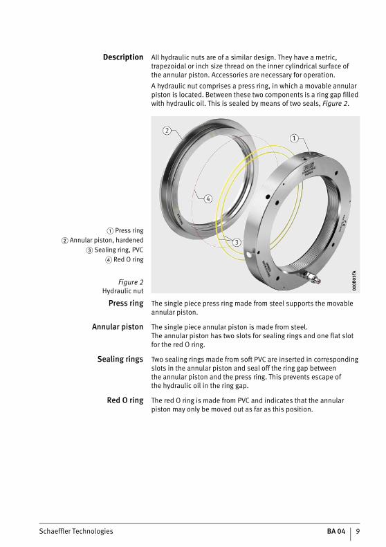
Description All hydraulic nuts are of a similar design. They have a metric, trapezoidal or inch size thread on the inner cylindrical surface ofthe annular piston. Accessories are necessary for operation.A hydraulic nut comprises a press ring, in which a movable annular piston is located. Between these two components is a ring gap filled with hydraulic oil. This is sealed by means of two seals, Figure 2.
Press ring The single piece press ring made from steel supports the movable annular piston.
Annular piston The single piece annular piston is made from steel.The annular piston has two slots for sealing rings and one flat slotfor the red O ring.
Sealing rings Two sealing rings made from soft PVC are inserted in corresponding slots in the annular piston and seal off the ring gap betweenthe annular piston and the press ring. This prevents escape ofthe hydraulic oil in the ring gap.
Red O ring The red O ring is made from PVC and indicates that the annular piston may only be moved out as far as this position.
� Press ring� Annular piston, hardened
� Sealing ring, PVC� Red O ring
Figure 2Hydraulic nut 00
0B05
FA00
0B05
FA
10 BA 04 Schaeffler Technologies
Hydraulic nuts HYD-NUT..-E, HYDNUT..-E-INCH
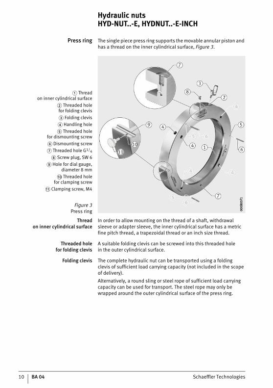
Press ring The single piece press ring supports the movable annular piston and has a thread on the inner cylindrical surface, Figure 3.
Threadon inner cylindrical surface
In order to allow mounting on the thread of a shaft, withdrawal sleeve or adapter sleeve, the inner cylindrical surface has a metric fine pitch thread, a trapezoidal thread or an inch size thread.
Threaded holefor folding clevis
A suitable folding clevis can be screwed into this threaded holein the outer cylindrical surface.
Folding clevis The complete hydraulic nut can be transported using a foldingclevis of sufficient load carrying capacity (not included in the scope of delivery).Alternatively, a round sling or steel rope of sufficient load carrying capacity can be used for transport. The steel rope may only be wrapped around the outer cylindrical surface of the press ring.
� Threadon inner cylindrical surface
� Threaded holefor folding clevis� Folding clevis� Handling hole� Threaded hole
for dismounting screw� Dismounting screw� Threaded hole G1/4
Screw plug, SW 6 Hole for dial gauge,
diameter 8 mm�� Threaded hole
for clamping screw� Clamping screw, M4
Figure 3Press ring 00
0B05
F100
0B05
F1
Schaeffler Technologies BA 04 11
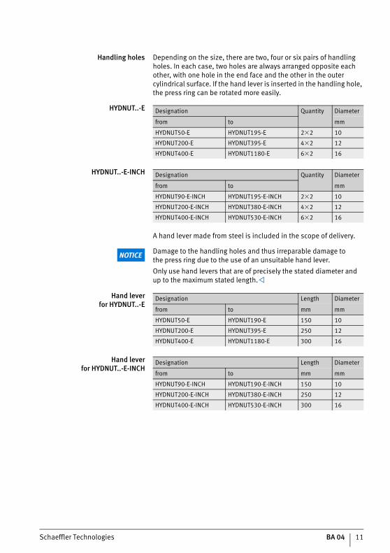
Handling holes Depending on the size, there are two, four or six pairs of handling holes. In each case, two holes are always arranged opposite each other, with one hole in the end face and the other in the outer cylindrical surface. If the hand lever is inserted in the handling hole, the press ring can be rotated more easily.
HYDNUT..-E
HYDNUT..-E-INCH
A hand lever made from steel is included in the scope of delivery.
NOTICE Damage to the handling holes and thus irreparable damage tothe press ring due to the use of an unsuitable hand lever.Only use hand levers that are of precisely the stated diameter andup to the maximum stated length.
Hand leverfor HYDNUT..-E
Hand leverfor HYDNUT..-E-INCH
Designation Quantity Diameter
from to mm
HYDNUT50-E HYDNUT195-E 2�2 10
HYDNUT200-E HYDNUT395-E 4�2 12
HYDNUT400-E HYDNUT1180-E 6�2 16
Designation Quantity Diameter
from to mm
HYDNUT90-E-INCH HYDNUT195-E-INCH 2�2 10
HYDNUT200-E-INCH HYDNUT380-E-INCH 4�2 12
HYDNUT400-E-INCH HYDNUT530-E-INCH 6�2 16
Designation Length Diameter
from to mm mm
HYDNUT50-E HYDNUT190-E 150 10
HYDNUT200-E HYDNUT395-E 250 12
HYDNUT400-E HYDNUT1180-E 300 16
Designation Length Diameter
from to mm mm
HYDNUT90-E-INCH HYDNUT190-E-INCH 150 10
HYDNUT200-E-INCH HYDNUT380-E-INCH 250 12
HYDNUT400-E-INCH HYDNUT530-E-INCH 300 16
12 BA 04 Schaeffler Technologies
Hydraulic nuts HYD-NUT..-E, HYDNUT..-E-INCH
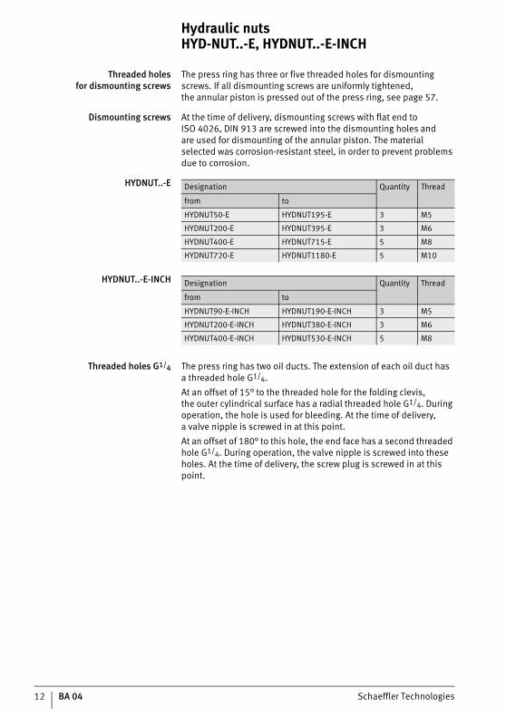
Threaded holesfor dismounting screws
The press ring has three or five threaded holes for dismounting screws. If all dismounting screws are uniformly tightened,the annular piston is pressed out of the press ring, see page 57.
Dismounting screws At the time of delivery, dismounting screws with flat end to ISO 4026, DIN 913 are screwed into the dismounting holes andare used for dismounting of the annular piston. The material selected was corrosion-resistant steel, in order to prevent problems due to corrosion.
HYDNUT..-E
HYDNUT..-E-INCH
Threaded holes G1/4 The press ring has two oil ducts. The extension of each oil duct hasa threaded hole G1/4.At an offset of 15° to the threaded hole for the folding clevis,the outer cylindrical surface has a radial threaded hole G1/4. During operation, the hole is used for bleeding. At the time of delivery,a valve nipple is screwed in at this point.At an offset of 180° to this hole, the end face has a second threaded hole G1/4. During operation, the valve nipple is screwed into these holes. At the time of delivery, the screw plug is screwed in at this point.
Designation Quantity Thread
from to
HYDNUT50-E HYDNUT195-E 3 M5
HYDNUT200-E HYDNUT395-E 3 M6
HYDNUT400-E HYDNUT715-E 5 M8
HYDNUT720-E HYDNUT1180-E 5 M10
Designation Quantity Thread
from to
HYDNUT90-E-INCH HYDNUT190-E-INCH 3 M5
HYDNUT200-E-INCH HYDNUT380-E-INCH 3 M6
HYDNUT400-E-INCH HYDNUT530-E-INCH 5 M8
Schaeffler Technologies BA 04 13
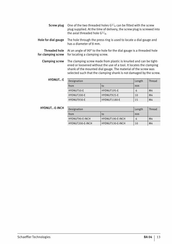
Screw plug One of the two threaded holes G1/4 can be fitted with the screwplug supplied. At the time of delivery, the screw plug is screwed into the axial threaded hole G1/4.
Hole for dial gauge The hole through the press ring is used to locate a dial gauge andhas a diameter of 8 mm.
Threaded holefor clamping screw
At an angle of 90° to the hole for the dial gauge is a threaded holefor locating a clamping screw.
Clamping screw The clamping screw made from plastic is knurled and can be tight-ened or loosened without the use of a tool. It locates the clamping shank of the mounted dial gauge. The material of the screw was selected such that the clamping shank is not damaged by the screw.
HYDNUT..-E
HYDNUT..-E-INCH
Designation Length Thread
from to mm
HYDNUT50-E HYDNUT195-E 6 M4
HYDNUT200-E HYDNUT925-E 10 M4
HYDNUT930-E HYDNUT1180-E 15 M4
Designation Length Thread
from to mm
HYDNUT90-E-INCH HYDNUT190-E-INCH 6 M4
HYDNUT200-E-INCH HYDNUT530-E-INCH 10 M4

14 BA 04 Schaeffler Technologies
Hydraulic nuts HYD-NUT..-E, HYDNUT..-E-INCH
Annular piston The single piece annular piston is made from steel. The annular piston has two slots for sealing rings and one flat slot for the red O ring. At or above a stipulated size, there are three threaded holes in the annular piston, Figure 4.
Slots for sealing rings Two slots support the sealing rings made from soft PVC.
Slot for red O ring A flat slot supports the red O ring made from PVC.
Threaded holes for eye bolts In the case of hydraulic nuts HYDNUT410 or larger, there are threaded holes in the annular piston. At the pitch circle, the holes have a spacing of 120° to each other. If eye bolts are screwedinto these threaded holes, the annular piston can be transportedby means of a lifting device, see page 58.
HYDNUT..-E
HYDNUT..-E-INCH
� Slot for sealing ring� Slot for red O ring
� Threaded hole for eye bolt
Figure 4Annular piston
000B
05E8
000B
05E8
Designation Thread
from to
HYDNUT410-E HYDNUT595-E 3�M6
HYDNUT600-E HYDNUT1180-E 3�M8
Designation Thread
from to
HYDNUT410-E-INCH HYDNUT530-E-INCH 3�M6
Schaeffler Technologies BA 04 15
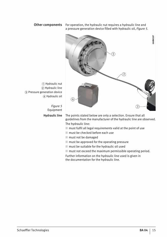
Other components For operation, the hydraulic nut requires a hydraulic line anda pressure generation device filled with hydraulic oil, Figure 5.
Hydraulic line The points stated below are only a selection. Ensure that all guidelines from the manufacturer of the hydraulic line are observed.The hydraulic line:■ must fulfil all legal requirements valid at the point of use■ must be checked before each use■ must not be damaged■ must be approved for the operating pressure■ must be suitable for the hydraulic oil used■ must not exceed the maximum permissible operating period.Further information on the hydraulic line used is given inthe documentation for the hydraulic line.
� Hydraulic nut� Hydraulic line
� Pressure generation device� Hydraulic oil
Figure 5Equipment
000B
05D
F00
0B05
DF

16 BA 04 Schaeffler Technologies
Hydraulic nuts HYD-NUT..-E, HYDNUT..-E-INCH
Pressure generation device The points stated below are only a selection. Ensure that all guidelines from the manufacturer of the pressure generation device are observed.The pressure generation device:■ must fulfil all legal requirements valid at the point of use■ must be checked before each use■ must not be damaged■ may only be operated at a pressure that is lower than
the maximum permissible pressure of the hydraulic nut■ must have a sufficiently large tank, see page 37.Further information on the pressure generation device used is given in the documentation for the pressure generation device.
Hydraulic oil The hydraulic oil used must correspond to a particular viscosity class, see page 64.
Schaeffler Technologies BA 04 17
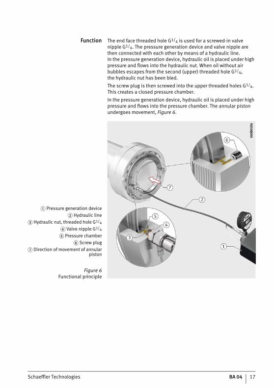
Function The end face threaded hole G1/4 is used for a screwed-in valve nipple G1/4. The pressure generation device and valve nipple are then connected with each other by means of a hydraulic line.In the pressure generation device, hydraulic oil is placed under high pressure and flows into the hydraulic nut. When oil without air bubbles escapes from the second (upper) threaded hole G1/4,the hydraulic nut has been bled.The screw plug is then screwed into the upper threaded holes G1/4. This creates a closed pressure chamber. In the pressure generation device, hydraulic oil is placed under high pressure and flows into the pressure chamber. The annular piston undergoes movement, Figure 6.
� Pressure generation device� Hydraulic line
� Hydraulic nut, threaded hole G1/4
� Valve nipple G1/4
� Pressure chamber� Screw plug
� Direction of movement of annularpiston
Figure 6Functional principle
000B
05D
600
0B05
D6

18 BA 04 Schaeffler Technologies
Hydraulic nuts HYD-NUT..-E, HYDNUT..-E-INCH
Mounting In the mounting of rolling bearings, the end face of the annular piston presses on the end face of the bearing inner ring, withdrawal sleeve or mounting plate, Figure 7.Mounting on and dismounting from an adapter sleeve can be carried out using the oil pressure method. In this method, an additional pressure generation device is used to press hydraulic oil between the fit surfaces of the sleeve and bearing inner ring as well as between the sleeve and shaft.
� Mounting on shaft� Mounting on adapter sleeve,
oil pressure method� Mounting on withdrawal sleeve
� Mounting on withdrawal sleeve,oil pressure
Figure 7Mounting method 00
0B02
5C00
0B02
5C
Schaeffler Technologies BA 04 19
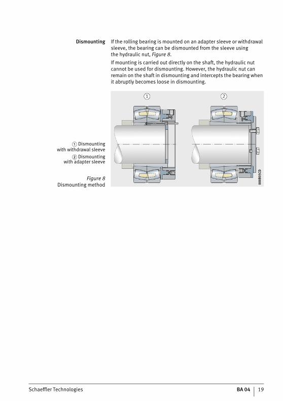
Dismounting If the rolling bearing is mounted on an adapter sleeve or withdrawal sleeve, the bearing can be dismounted from the sleeve usingthe hydraulic nut, Figure 8.If mounting is carried out directly on the shaft, the hydraulic nut cannot be used for dismounting. However, the hydraulic nut can remain on the shaft in dismounting and intercepts the bearing when it abruptly becomes loose in dismounting.
� Dismountingwith withdrawal sleeve
� Dismountingwith adapter sleeve
Figure 8Dismounting method 00
0B05
CD00
0B05
CD

20 BA 04 Schaeffler Technologies
Hydraulic nuts HYD-NUT..-E, HYDNUT..-E-INCH
Commissioning Commissioning is divided into the following actions:■ checking the hydraulic nut■ lifting the hydraulic nut out of the transport container and
transporting the hydraulic nut■ preparation for mounting■ mounting the hydraulic nut■ applying the mounting ring, optional■ applying the intermediate ring, optional■ selecting and mounting the dial gauge■ selecting the pressure generation device.
Checking the hydraulic nut Before use, it is advisable to check whether the hydraulic nut is suitable for the thread present. The press ring has the diameter and thread information engraved on the surface, Figure 9.
Check also whether the thread is damaged. A hydraulic nut witha damaged thread must not be used, since it can damage the thread on the shaft.
� Diameter and thread information
Figure 9Checking the hydraulic nut 00
0B05
C400
0B05
C4
Schaeffler Technologies BA 04 21
Lifting the hydraulic nut out ofthe transport container and
transporting the hydraulic nut
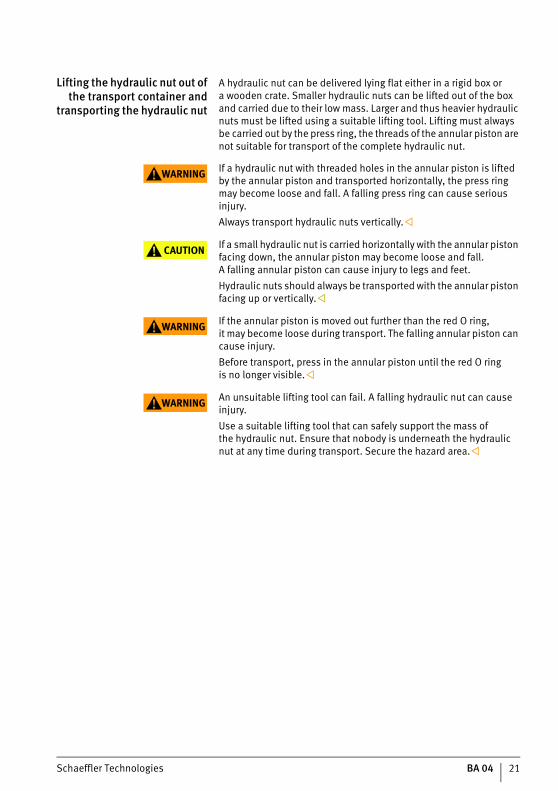
A hydraulic nut can be delivered lying flat either in a rigid box ora wooden crate. Smaller hydraulic nuts can be lifted out of the box and carried due to their low mass. Larger and thus heavier hydraulic nuts must be lifted using a suitable lifting tool. Lifting must always be carried out by the press ring, the threads of the annular piston are not suitable for transport of the complete hydraulic nut.
WARNING If a hydraulic nut with threaded holes in the annular piston is lifted by the annular piston and transported horizontally, the press ring may become loose and fall. A falling press ring can cause serious injury.Always transport hydraulic nuts vertically.
CAUTION If a small hydraulic nut is carried horizontally with the annular piston facing down, the annular piston may become loose and fall.A falling annular piston can cause injury to legs and feet.Hydraulic nuts should always be transported with the annular piston facing up or vertically.
WARNING If the annular piston is moved out further than the red O ring,it may become loose during transport. The falling annular piston can cause injury.Before transport, press in the annular piston until the red O ringis no longer visible.
WARNING An unsuitable lifting tool can fail. A falling hydraulic nut can cause injury.Use a suitable lifting tool that can safely support the mass ofthe hydraulic nut. Ensure that nobody is underneath the hydraulic nut at any time during transport. Secure the hazard area.

22 BA 04 Schaeffler Technologies
Hydraulic nuts HYD-NUT..-E, HYDNUT..-E-INCH
WARNING Serious injury caused by a falling hydraulic nut due to failureof an unsuitable clevis.Only use a clevis that is suitable for all lifting positions (angles), Figure 10.
Screw a folding clevis into the threaded hole for the clevisin the outer cylindrical surface of the press ring.
Hang a hook in the clevis or thread in a carrying sling. Fit the securing belt. Slowly lift the hydraulic nut until it hangs vertical, Figure 11.
Transport the hydraulic nut without shocks or vibration.
� Hydraulic nut,lying flat
� Hydraulic nut,lifted half way
� Hydraulic nut,suspended
Figure 10Lifting positions 00
0B05
BB00
0B05
BB
� Wooden crate� Hydraulic nut� Valve nipple
� Clevis� Hook
� Securing belt
Figure 11Delivered condition 00
0B05
B200
0B05
B2

Schaeffler Technologies BA 04 23
Preparation for mounting The valve nipple is checked as follows: Check optically whether the thread of the valve nipple is
damaged. If the thread is damaged, use a new valve nipple, Figure 12.
Check optically whether the seal is undamaged, Figure 13.Replace any damaged seal.
A seal with the following characteristics is suitable:■ type:
– CEJN rubber/metal seal■ operating pressure:
– 1500 bar■ dimensions:
– G1/4 (20,57 mm�13,74 mm�3 mm)■ material:
– high grade steel/fluoro rubber (FKM).
� Valve nipple� Seal
Figure 12Valve nipple 00
0B05
A900
0B05
A9
� New� Damaged
Figure 13Sealing 00
0B05
A000
0B05
A0
24 BA 04 Schaeffler Technologies
Hydraulic nuts HYD-NUT..-E, HYDNUT..-E-INCH
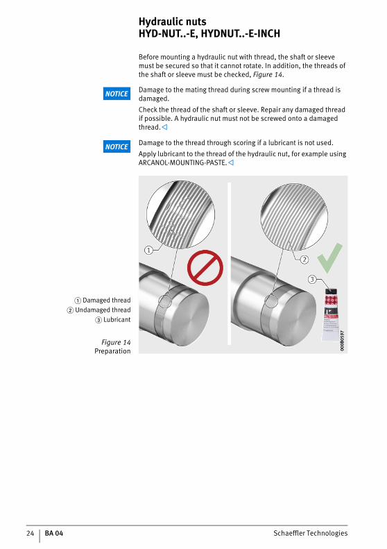
Before mounting a hydraulic nut with thread, the shaft or sleevemust be secured so that it cannot rotate. In addition, the threads of the shaft or sleeve must be checked, Figure 14.
NOTICE Damage to the mating thread during screw mounting if a thread is damaged.Check the thread of the shaft or sleeve. Repair any damaged thread if possible. A hydraulic nut must not be screwed onto a damaged thread.
NOTICE Damage to the thread through scoring if a lubricant is not used.Apply lubricant to the thread of the hydraulic nut, for example using ARCANOL-MOUNTING-PASTE.
� Damaged thread� Undamaged thread
� Lubricant
Figure 14Preparation 00
0B05
9700
0B05
97

Schaeffler Technologies BA 04 25
Mounting the hydraulic nut In mounting, the method used depends on the mass of the hydraulic nut.
Mounting a light hydraulic nut A light hydraulic nut can be mounted manually, Figure 15: Rotate the hydraulic nut until the start of the thread on
the hydraulic nut and the start of the thread on the shaft journalor sleeve coincide.
Align the hydraulic nut exactly parallel and concentricallyto the shaft.
WARNINGInjuries due to a hydraulic nut becoming loose from the shaft and falling because too few thread turns were engaged.At least half the thread width must be engaged.
NOTICEIf the thread of the shaft journal or sleeve is subjected during mounting to the mass of the hydraulic nut, scoring may occurin the thread.Lift the hydraulic nut slightly and prevent the thread from being subjected to load by the whole mass of the hydraulic nut. Screw the hydraulic nut into place (right hand thread) until
the end face of the annular piston is in contact with the end face of the bearing inner ring.
Loosen the hydraulic nut as necessary until the radial threaded hole G1/4 is in the upper position.
If necessary, apply a mounting ring, see page 32. The hydraulic nut is mounted and can be bled.
� Shaft� Hydraulic nut
� Rotary motion� Half thread width
of press ring� Radial threaded hole G1/4,
upper position� Annular piston,
end face� Inner ring,
end face
Figure 15Mounting 00
0B05
8E00
0B05
8E
26 BA 04 Schaeffler Technologies
Hydraulic nuts HYD-NUT..-E, HYDNUT..-E-INCH
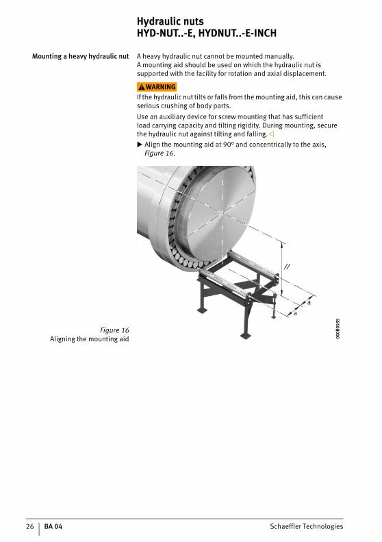
Mounting a heavy hydraulic nut A heavy hydraulic nut cannot be mounted manually.A mounting aid should be used on which the hydraulic nut is supported with the facility for rotation and axial displacement.
WARNINGIf the hydraulic nut tilts or falls from the mounting aid, this can cause serious crushing of body parts.Use an auxiliary device for screw mounting that has sufficientload carrying capacity and tilting rigidity. During mounting, secure the hydraulic nut against tilting and falling. Align the mounting aid at 90° and concentrically to the axis, Figure 16.
Figure 16Aligning the mounting aid 00
0B05
8500
0B05
85

Schaeffler Technologies BA 04 27
WARNINGSerious crushing in setting down of the hydraulic nut.When setting down the hydraulic nut, ensure that no body parts are located in the gap between the hydraulic nut and shaft or adjacent construction. Set down the hydraulic nut carefully on the mounting aid using
a crane, Figure 17.
Remove the securing belt.
� Shaft� Hydraulic nut
� Gap
Figure 17Setting down the hydraulic nut 00
0B05
7C00
0B05
7C

28 BA 04 Schaeffler Technologies
Hydraulic nuts HYD-NUT..-E, HYDNUT..-E-INCH
Adjustment of the mounting aid requires precise action.
NOTICEIf the thread of the shaft or sleeve is subjected during mounting to the entire mass of the hydraulic nut, scoring may occur in the thread.Adjust the height of the mounting aid so that the thread of the shaft or sleeve is not subjected to load by the entire mass of the hydraulic nut. Adjust the height of the mounting aid. Align the hydraulic nut exactly parallel and concentrically
to the shaft. Remove the hook. Remove the load hook. Rotate the hydraulic nut until the start of the thread on
the hydraulic nut and the start of the thread on the shaft journalor sleeve coincide, Figure 18.
� Mounting aid� Hydraulic nut,
start of thread� Shaft,
start of thread
Figure 18Start position 00
0B05
7300
0B05
73

Schaeffler Technologies BA 04 29
When displacing the hydraulic nut, there is an increased riskof injury, especially to the hands.
WARNINGSerious crushing in displacement of the hydraulic nut.When displacing the hydraulic nut, ensure that no body parts are located in the gap between the hydraulic nut and shaft or adjacent construction. Move the hydraulic nut in the direction of the shaft until the start
of the thread on the hydraulic nut and the start of the thread onthe shaft journal or sleeve are in contact, Figure 19.
� Shaft� Hydraulic nut
� Gap
Figure 19Displacing the hydraulic nut 00
0B05
6A00
0B05
6A
30 BA 04 Schaeffler Technologies
Hydraulic nuts HYD-NUT..-E, HYDNUT..-E-INCH
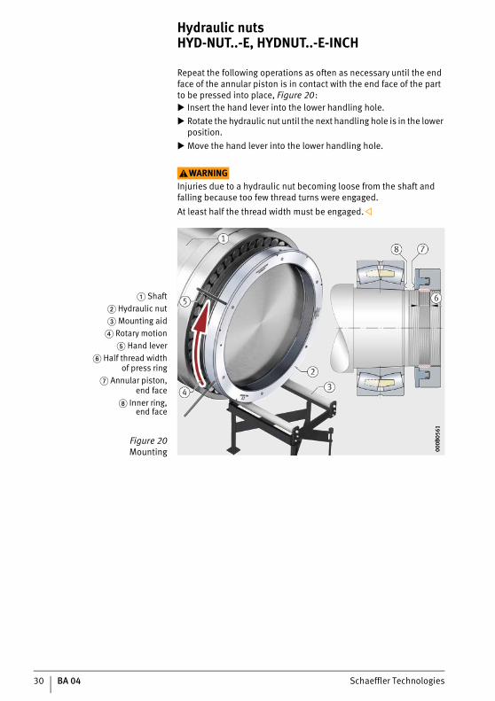
Repeat the following operations as often as necessary until the end face of the annular piston is in contact with the end face of the part to be pressed into place, Figure 20: Insert the hand lever into the lower handling hole. Rotate the hydraulic nut until the next handling hole is in the lower
position. Move the hand lever into the lower handling hole.
WARNINGInjuries due to a hydraulic nut becoming loose from the shaft and falling because too few thread turns were engaged.At least half the thread width must be engaged.
� Shaft� Hydraulic nut� Mounting aid
� Rotary motion� Hand lever
� Half thread widthof press ring
� Annular piston,end face
Inner ring,end face
Figure 20Mounting 00
0B05
6100
0B05
61
Schaeffler Technologies BA 04 31
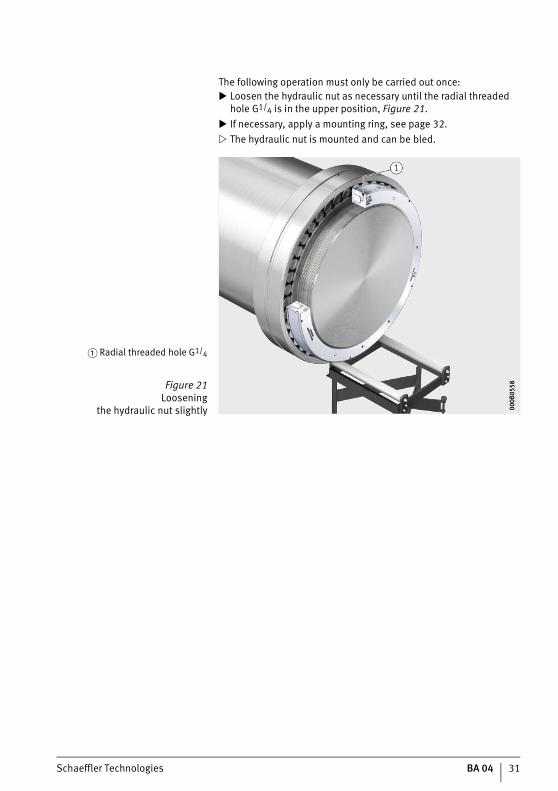
The following operation must only be carried out once: Loosen the hydraulic nut as necessary until the radial threaded
hole G1/4 is in the upper position, Figure 21. If necessary, apply a mounting ring, see page 32. The hydraulic nut is mounted and can be bled.
� Radial threaded hole G1/4
Figure 21Loosening
the hydraulic nut slightly 000B
0558
000B
0558
32 BA 04 Schaeffler Technologies
Hydraulic nuts HYD-NUT..-E, HYDNUT..-E-INCH
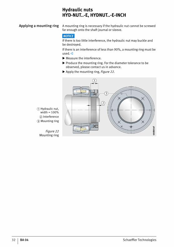
Applying a mounting ring A mounting ring is necessary if the hydraulic nut cannot be screwed far enough onto the shaft journal or sleeve.
NOTICEIf there is too little interference, the hydraulic nut may buckle andbe destroyed.If there is an interference of less than 90%, a mounting ring must be used. Measure the interference. Produce the mounting ring. For the diameter tolerance to be
observed, please contact us in advance. Apply the mounting ring, Figure 22.
� Hydraulic nut,width = 100%
� Interference� Mounting ring
Figure 22Mounting ring 00
0B05
4F00
0B05
4F
Schaeffler Technologies BA 04 33
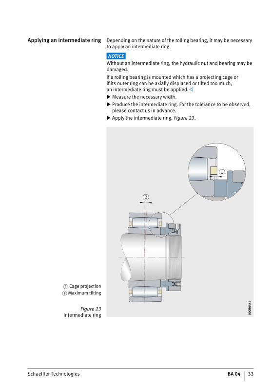
Applying an intermediate ring Depending on the nature of the rolling bearing, it may be necessary to apply an intermediate ring.
NOTICEWithout an intermediate ring, the hydraulic nut and bearing may be damaged.If a rolling bearing is mounted which has a projecting cage orif its outer ring can be axially displaced or tilted too much,an intermediate ring must be applied. Measure the necessary width. Produce the intermediate ring. For the tolerance to be observed,
please contact us in advance. Apply the intermediate ring, Figure 23.
� Cage projection� Maximum tilting
Figure 23Intermediate ring 00
0B05
4600
0B05
46
34 BA 04 Schaeffler Technologies
Hydraulic nuts HYD-NUT..-E, HYDNUT..-E-INCH
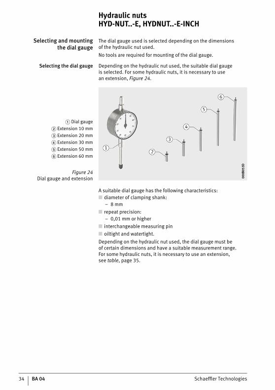
Selecting and mountingthe dial gauge
The dial gauge used is selected depending on the dimensionsof the hydraulic nut used.No tools are required for mounting of the dial gauge.
Selecting the dial gauge Depending on the hydraulic nut used, the suitable dial gaugeis selected. For some hydraulic nuts, it is necessary to usean extension, Figure 24.
A suitable dial gauge has the following characteristics:■ diameter of clamping shank:
– 8 mm■ repeat precision:
– 0,01 mm or higher■ interchangeable measuring pin■ oiltight and watertight.Depending on the hydraulic nut used, the dial gauge must beof certain dimensions and have a suitable measurement range.For some hydraulic nuts, it is necessary to use an extension,see table, page 35.
� Dial gauge� Extension 10 mm� Extension 20 mm� Extension 30 mm� Extension 50 mm� Extension 60 mm
Figure 24Dial gauge and extension 00
0B05
3D00
0B05
3D

Schaeffler Technologies BA 04 35
Characteristics of the dial gauge Designation Length of dial gauge
Measure-ment range
Exten-sion
min. max.
from to mm mm mm mm
HYDNUT50-E HYDNUT85-E 36 40 25 0
HYDNUT90-E(-INCH) HYDNUT155-E(-INCH) 37 42
HYDNUT160-E(-INCH) HYDNUT180-E(-INCH) 40 46
HYDNUT190-E HYDNUT205-E 42 50 25 10
HYDNUT190-E(-INCH) HYDNUT200-E(-INCH) 42 50
HYDNUT210-E HYDNUT220-E 43 52
HYDNUT210-E(-INCH) – 43 52
HYDNUT225-E HYDNUT250-E 44 54
HYDNUT220-E(-INCH) HYDNUT240-E(-INCH) 44 54
HYDNUT260-E(-INCH) – 45 56
HYDNUT270-E HYDNUT270-E(-INCH) 46 58
HYDNUT290-E HYDNUT295-E 47 60
HYDNUT300-E(-INCH) HYDNUT315-E 52 65 25 20
HYDNUT320-E HYDNUT350-E 53 67
HYDNUT320-E(-INCH) HYDNUT340-E(-INCH) 53 67
HYDNUT355-E HYDNUT365-E 54 69
HYDNUT360-E(-INCH) – 54 69
HYDNUT370-E HYDNUT385-E 55 71 50 20
HYDNUT380-E(-INCH) – 55 71
HYDNUT395-E – 56 73
HYDNUT400-E(-INCH) HYDNUT420-E(-INCH) 58 75
HYDNUT430-E HYDNUT450-E 63 80
HYDNUT460-E(-INCH) HYDNUT470-E 64 82
HYDNUT480-E(-INCH) HYDNUT490-E 65 84
HYDNUT500-E(-INCH) HYDNUT520-E(-INCH) 66 86
HYDNUT530-E(-INCH) HYDNUT560-E 68 90
HYDNUT570-E HYDNUT600-E 74 97 50 30
HYDNUT610-E HYDNUT680-E 75 99
HYDNUT690-E HYDNUT740-E 76 101
HYDNUT750-E HYDNUT760-E 82 108 50 50
HYDNUT780-E HYDNUT800-E 84 112
HYDNUT830-E HYDNUT900-E 85 114
HYDNUT930-E HYDNUT1000-E 86 116
HYDNUT1060-E – 88 120
HYDNUT1080-E – 89 122
HYDNUT1120-E – 92 128 50 60
HYDNUT1180-E – 95 134
36 BA 04 Schaeffler Technologies
Hydraulic nuts HYD-NUT..-E, HYDNUT..-E-INCH
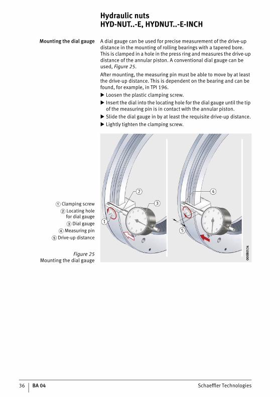
Mounting the dial gauge A dial gauge can be used for precise measurement of the drive-up distance in the mounting of rolling bearings with a tapered bore.This is clamped in a hole in the press ring and measures the drive-up distance of the annular piston. A conventional dial gauge can be used, Figure 25.After mounting, the measuring pin must be able to move by at least the drive-up distance. This is dependent on the bearing and can be found, for example, in TPI 196. Loosen the plastic clamping screw. Insert the dial into the locating hole for the dial gauge until the tip
of the measuring pin is in contact with the annular piston. Slide the dial gauge in by at least the requisite drive-up distance. Lightly tighten the clamping screw.
� Clamping screw� Locating hole
for dial gauge� Dial gauge
� Measuring pin� Drive-up distance
Figure 25Mounting the dial gauge 00
0B05
3400
0B05
34

Schaeffler Technologies BA 04 37
Selecting the pressuregeneration device
A suitable pressure generation device must have certain character-istics, see page 16. It must have a sufficiently large tank containingat least the requisite oil quantity, since it is not possible to refill with hydraulic oil during operation.
Oil quantity For the maximum drive-up distance, a certain oil quantity is required, see table.
HYDNUT..-E,HYDNUT..-E-INCH
1) Assuming usage of a hydraulic line with a length of 1 m andan inside diameter of 4 mm.
Hydraulic nut Oil quantity1)
from up to l
HYDNUT50-E HYDNUT85-E 0,5
HYDNUT90-E(-INCH) HYDNUT350-E(-INCH) 0,5
HYDNUT355-E(-INCH) HYDNUT480-E(-INCH) 1
HYDNUT490-E(-INCH) HYDNUT530-E(-INCH) 2
HYDNUT530-E HYDNUT655-E 2
HYDNUT670-E HYDNUT760-E 3
HYDNUT780-E HYDNUT900-E 4
HYDNUT930-E HYDNUT1000-E 5
HYDNUT1060-E HYDNUT1080-E 6
HYDNUT1120-E – 8
HYDNUT1180-E – 9
38 BA 04 Schaeffler Technologies
Hydraulic nuts HYD-NUT..-E, HYDNUT..-E-INCH
Operation After bleeding, the pressure is built up in order to mount or dismount the component. The oil pressure method can be used for easier mounting and dismounting.
Drive-up distance In the mounting of rolling bearings with a tapered bore, the internal clearance is reduced if the inner ring is driven up onto the shaft or sleeve and is thus expanded. The length of the drive-up distance determines the degree to which the internal clearance is reduced.
NOTICE If the internal clearance is set incorrectly, this will reduce the lifeof the rolling bearing or the rolling bearing will be damaged.Please observe the specifications of the rolling bearing manufacturer.
Hydraulic oil The hydraulic oil used in operation must be clean andof the specified viscosity class, see page 64.
WARNING Severe burns due to ignition of hydraulic oil.Avoid sources of ignition, including in particular cutting, welding and soldering work, in the vicinity of escaping hydraulic oil.
WARNING Hydraulic oil can cause irritation to skin and respiratory organs.Avoid skin contact if possible. Wear gloves. Protect uncovered skin by means of skin cream. Do not inhale vapours or fumes.
NOTICE Contaminated hydraulic oil can damage seals. Damaged seals must be replaced promptly.Only use clean hydraulic oil.

Schaeffler Technologies BA 04 39
Maximum pressure The maximum permissible pressure must be observed throughout operation.
WARNING Serious injuries due to the spraying of hydraulic oil under high pressure and damage to the hydraulic nut if the maximum permissible pressure is exceeded.Measure the operating pressure continuously. The operating pressure must never exceed the maximum permissible pressure,Figure 26.
Technical data such as dimensions and the permissible pressurefor hydraulic nuts can be found in a Technical Product Information. This is available as a PDF file on the Internet under the address http://www.schaeffler.de, menu item Mediathek.
Further information ■ TPI 196, Hydraulic Nuts.
� Maximum pressure information
Figure 26Maximum permissible pressure,
engraved 000B
050F
000B
050F
40 BA 04 Schaeffler Technologies
Hydraulic nuts HYD-NUT..-E, HYDNUT..-E-INCH
Mounting the hydraulic hose Mounting of the hydraulic hose connects the pressure generation device and hydraulic nut with each other.The following accessories are required:■ hose fasteners■ tool for mounting hose fasteners, see instructions for hose
fasteners■ allen key SW 6 for removing screw plug■ tool for mounting valve nipple on the pressure generation device,
see instructions for pressure generation devices.
WARNING Serious injuries due to the spraying of hydraulic oil as a resultof an unsuitable, damaged or old hydraulic hose.Only mount a hydraulic hose that is approved for use withthe pressure generation device. The hydraulic hose must be free from damage. Observe the storage life date of the hydraulic hose.
NOTICE Damage to the pressure generation device and seals in the hydraulic nut due to contaminants.Remove any contaminants from the pressure generation device, hydraulic hose and hydraulic nut. All work must be carried out under extreme cleanliness.
Mounting the hydraulic hose: Remove the screw plug from the axial threaded hole G1/4
in the hydraulic nut. Remove the valve nipple from the radial threaded hole.
WARNINGSerious injuries due to the spraying of hydraulic oil under high pressure due to the loosening of a screw connection.Observe the maximum tightening torque for the threaded hole G1/4 (oil connector) in the hydraulic nut, see page 64.Observe the maximum tightening torque for the oil connectoron the pressure generation device.

Schaeffler Technologies BA 04 41
Screw the valve nipple (CEJN series 116), which was removed from the radial hole, into the axial threaded hole, Figure 27.
Slide the collar of the hydraulic hose onto the valve nipple.
Slide the collar of the hydraulic hose onto the valve nipple ofthe pressure generation device, Figure 28.
Apply the hose fasteners.
WARNING Serious injuries due to detached hose whipping back and forth.Mount hose fasteners in order to prevent whipping by the hydraulic hose.
WARNING Serious injuries due to hydraulic oil spraying out of torn hose under high pressure because the hose was laid with an excessively small bending radius.Lay the hydraulic hose with the specified bending radius tothe pressure generation device.Observe the instructions for the hydraulic hose.
� Hydraulic nut,threaded hole G1/4
� Valve nipple� Hydraulic hose
Figure 27Connector
000B
052A
000B
052A
� Hose fasteneron hydraulic nut� Hose fastener
on pressure generation device
Figure 28Connecting
the pressure generation device
000B
0521
000B
0521

42 BA 04 Schaeffler Technologies
Hydraulic nuts HYD-NUT..-E, HYDNUT..-E-INCH
Bleeding Bleeding is necessary since compressed air will endanger the safety of the user. The hydraulic oil escaping during bleeding must be collected and disposed of correctly in accordance with the regional regulations. Check whether the oil volume in the pressure generation device is
adequate to bleed the pressure generation device, hydraulic hose and hydraulic nut. Furthermore, the oil volume must be sufficient for the drive-up distance of the annular piston. Where necessary, hydraulic oil must be refilled before bleeding, since refilling during operation is not permissible.
WARNINGBlinding or injury to eyes due to spraying out of hydraulic oil under high pressure.Ensure that the plug-in coupling is securely connected and the hose fasteners are fitted. Always wear safety goggles. Ensure that the radial threaded hole G1/4 is at the top,Figure 29, page 43.
Apply the device for collection of hydraulic oil. Remove the screw plug from the upper threaded hole G1/4. Start the pressure generation device. Wait until the hydraulic oil escapes without air bubbles. Stop the pressure generation device. Screw the screw plug back into the upper threaded hole G1/4 and
observe the tightening torque, see page 64. Remove the collector device. Dispose of the collected hydraulic oil correctly or send
for recycling.

Schaeffler Technologies BA 04 43
� Screw plug,threaded hole G1/4 at top
� Collector device� Pressure generation device
� Manometer
Figure 29Bleeding
000B
0518
000B
0518
44 BA 04 Schaeffler Technologies
Hydraulic nuts HYD-NUT..-E, HYDNUT..-E-INCH
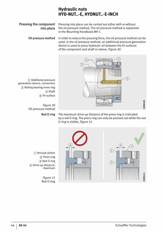
Pressing the componentinto place
Pressing into place can be carried out either with or withoutthe oil pressure method. The oil pressure method is explainedin the Mounting Handbook MH 1.
Oil pressure method In order to reduce the pressing force, the oil pressure method can be used. In the oil pressure method, an additional pressure generation device is used to press hydraulic oil between the fit surfacesof the component and shaft or sleeve, Figure 30.
Red O ring The maximum drive-up distance of the press ring is indicatedby a red O ring. The press ring can only be pressed out while the red O ring is visible, Figure 31.
� Additional pressuregeneration device, connection
� Rolling bearing inner ring� Shaft
� Fit surface
Figure 30Oil pressure method 00
0B04
0D00
0B04
0D
� Annular piston� Press ring� Red O ring
� Drive-up distance,maximum
Figure 31Red O ring 00
0B04
1600
0B04
16
Schaeffler Technologies BA 04 45
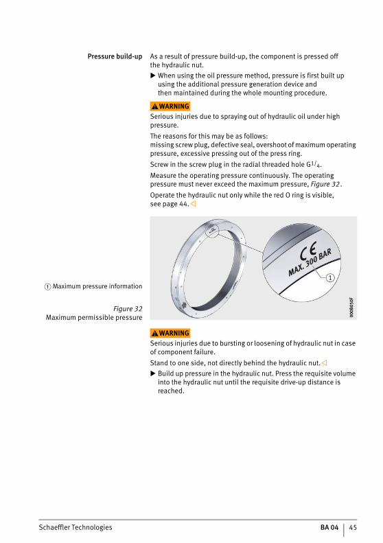
Pressure build-up As a result of pressure build-up, the component is pressed offthe hydraulic nut. When using the oil pressure method, pressure is first built up
using the additional pressure generation device andthen maintained during the whole mounting procedure.
WARNINGSerious injuries due to spraying out of hydraulic oil under high pressure.The reasons for this may be as follows:missing screw plug, defective seal, overshoot of maximum operating pressure, excessive pressing out of the press ring.Screw in the screw plug in the radial threaded hole G1/4.Measure the operating pressure continuously. The operating pressure must never exceed the maximum pressure, Figure 32.Operate the hydraulic nut only while the red O ring is visible,see page 44.
WARNINGSerious injuries due to bursting or loosening of hydraulic nut in case of component failure.Stand to one side, not directly behind the hydraulic nut. Build up pressure in the hydraulic nut. Press the requisite volume
into the hydraulic nut until the requisite drive-up distance is reached.
� Maximum pressure information
Figure 32Maximum permissible pressure 00
0B05
0F00
0B05
0F
46 BA 04 Schaeffler Technologies
Hydraulic nuts HYD-NUT..-E, HYDNUT..-E-INCH
Pressure decreasein oil pressure method
The following steps are only carried out if the oil pressure method is used: Switch the pressure generation device for the oil pressure method
to unpressurised. Wait 5 min. Measure the radial or axial internal clearance. Wait 30 min so that the oil can escape.
Pressure decreasein hydraulic nut
The following steps are always carried out: Switch the pressure generation device for the hydraulic nut
to unpressurised. Measure the radial or axial internal clearance.
Schaeffler Technologies BA 04 47
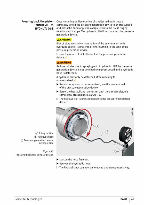
Pressing back the pistonHYDNUT50-E to
HYDNUT190-E
Once mounting or dismounting of smaller hydraulic nuts is complete, switch the pressure generation device to unpressurised and press the annular piston completely into the press ring by rotation until it stops. The hydraulic oil will run back into the pressure generation device.
CAUTIONRisk of slippage and contamination of the environment with hydraulic oil if oil is prevented from returning to the tank of the pressure generation device.Ensure the return of oil to the tank of the pressure generation device.
WARNINGSerious injuries due to spraying out of hydraulic oil if the pressure generation device is not switched to unpressurised and a hydraulic hose is detached.A hydraulic may only be detached after switching to unpressurised. Switch the system to unpressurised, see the user manual
of the pressure generation device. Screw the hydraulic nut on further until the annular piston is
completely pressed back, Figure 33. The hydraulic oil is pressed back into the pressure generation
device.
Loosen the hose fastener. Remove the hydraulic hose. The hydraulic nut can now be removed and transported away.
� Rotary motion� Hydraulic hose
� Pressure generation device,pressure-free
Figure 33Pressing back the annular piston
1
2
3
000B
0506
000B
0506
48 BA 04 Schaeffler Technologies
Hydraulic nuts HYD-NUT..-E, HYDNUT..-E-INCH
Pressing back the pistonHYDNUT200-E to
HYDNUT1180-E
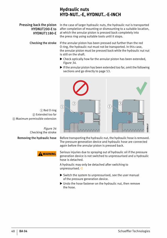
In the case of larger hydraulic nuts, the hydraulic nut is transported after completion of mounting or dismounting to a suitable location, at which the annular piston is pressed back completely intothe press ring using suitable tools until it stops.
Checking the stroke If the annular piston has been pressed out further than the red O ring, the hydraulic nut must not be transported. In this case,the annular piston must be pressed back while the hydraulic nut nut is still on the shaft. Check optically how far the annular piston has been extended, Figure 34.
If the annular piston has been extended too far, omit the following sections and go directly to page 53.
Removing the hydraulic hose Before transporting the hydraulic nut, the hydraulic hose is removed. The pressure generation device and hydraulic hose are connected again before the annular piston is pressed back.
WARNING Serious injuries due to spraying out of hydraulic oil if the pressure generation device is not switched to unpressurised and a hydraulic hose is detached.A hydraulic may only be detached after switching to unpressurised.
Switch the system to unpressurised, see the user manualof the pressure generation device.
Undo the hose fastener on the hydraulic nut, then removethe hose.
� Red O ring� Extended too far
� Maximum permissible extension
Figure 34Checking the stroke
2 311
000B
041F
000B
041F
Schaeffler Technologies BA 04 49
Detaching the hydraulic nutfrom the shaft
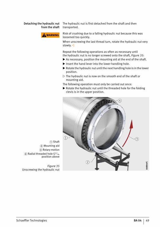
The hydraulic nut is first detached from the shaft and then transported.
WARNING Risk of crushing due to a falling hydraulic nut because this was loosened too quickly.When unscrewing the last thread turn, rotate the hydraulic nut very slowly.
Repeat the following operations as often as necessary untilthe hydraulic nut is no longer screwed onto the shaft, Figure 35: As necessary, position the mounting aid at the end of the shaft. Insert the hand lever into the lower handling hole. Rotate the hydraulic nut until the next handling hole is in the lower
position. The hydraulic nut is now on the smooth end of the shaft or
mounting aid. The following operation must only be carried out once: Rotate the hydraulic nut until the threaded hole for the folding
clevis is in the upper position.
� Shaft� Mounting aid
� Rotary motion� Radial threaded hole G1/4,
position above
Figure 35Unscrewing the hydraulic nut 00
0B04
FC00
0B04
FC
50 BA 04 Schaeffler Technologies
Hydraulic nuts HYD-NUT..-E, HYDNUT..-E-INCH
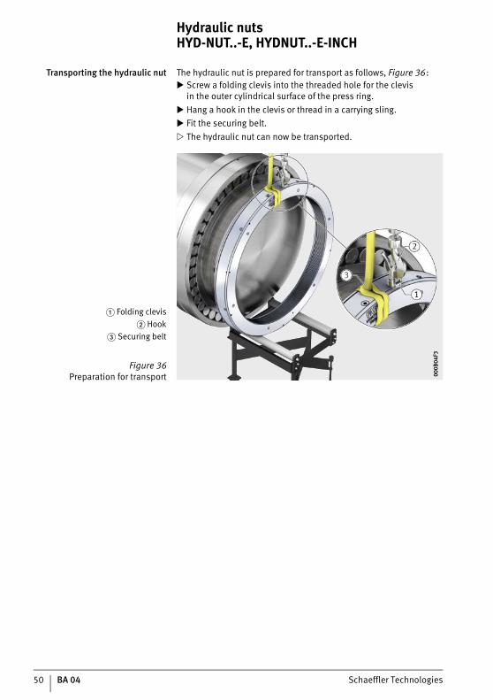
Transporting the hydraulic nut The hydraulic nut is prepared for transport as follows, Figure 36: Screw a folding clevis into the threaded hole for the clevis
in the outer cylindrical surface of the press ring. Hang a hook in the clevis or thread in a carrying sling. Fit the securing belt. The hydraulic nut can now be transported.
� Folding clevis� Hook
� Securing belt
Figure 36Preparation for transport 00
0B04
F300
0B04
F3
Schaeffler Technologies BA 04 51
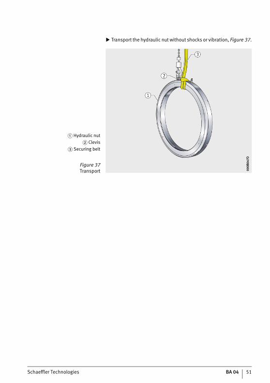
Transport the hydraulic nut without shocks or vibration, Figure 37.
� Hydraulic nut� Clevis
� Securing belt
Figure 37Transport 00
0B04
7D00
0B04
7D
52 BA 04 Schaeffler Technologies
Hydraulic nuts HYD-NUT..-E, HYDNUT..-E-INCH
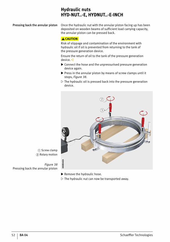
Pressing back the annular piston Once the hydraulic nut with the annular piston facing up has been deposited on wooden beams of sufficient load carrying capacity,the annular piston can be pressed back.
CAUTIONRisk of slippage and contamination of the environment with hydraulic oil if oil is prevented from returning to the tank ofthe pressure generation device.Ensure the return of oil to the tank of the pressure generation device. Connect the hose and the unpressurised pressure generation
device again. Press in the annular piston by means of screw clamps until it
stops, Figure 38. The hydraulic oil is pressed back into the pressure generation
device.
Remove the hydraulic hose. The hydraulic nut can now be transported away.
� Screw clamp� Rotary motion
Figure 38Pressing back the annular piston 00
0B04
EA00
0B04
EA
Schaeffler Technologies BA 04 53
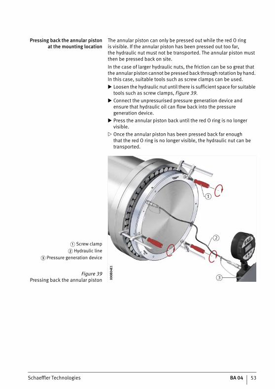
Pressing back the annular pistonat the mounting location
The annular piston can only be pressed out while the red O ringis visible. If the annular piston has been pressed out too far,the hydraulic nut must not be transported. The annular piston must then be pressed back on site.In the case of larger hydraulic nuts, the friction can be so great that the annular piston cannot be pressed back through rotation by hand. In this case, suitable tools such as screw clamps can be used. Loosen the hydraulic nut until there is sufficient space for suitable
tools such as screw clamps, Figure 39. Connect the unpressurised pressure generation device and
ensure that hydraulic oil can flow back into the pressure generation device.
Press the annular piston back until the red O ring is no longer visible.
Once the annular piston has been pressed back far enoughthat the red O ring is no longer visible, the hydraulic nut can be transported.
� Screw clamp� Hydraulic line
� Pressure generation device
Figure 39Pressing back the annular piston 00
0B04
E100
0B04
E1
54 BA 04 Schaeffler Technologies
Hydraulic nuts HYD-NUT..-E, HYDNUT..-E-INCH
Decommissioning If the hydraulic nut will not be used for an extended period, it should be decommissioned:■ Press the annular piston in completely.■ Screw in the screw plug and valve nipple.■ Clean the hydraulic nut using cold cleaner or paraffin oil.■ Oil the surface of the hydraulic nut, for example using
ARCANOL-ANTICORROSIONOIL-400G.
WARNING Disease of the respiratory organs through inhalation of vapoursof the cleaning agent used.Observe the safety and environmental guidelines of the cleaning agent manufacturer.
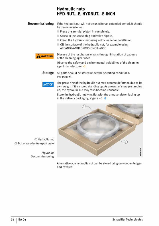
Storage All parts should be stored under the specified conditions,see page 6.
NOTICE The press ring of the hydraulic nut may become deformed due to its own weight if it is stored standing up. As a result of storage standing up, the hydraulic nut may thus become unusable.Store the hydraulic nut lying flat with the annular piston facing upin the delivery packaging, Figure 40.
Alternatively, a hydraulic nut can be stored lying on wooden ledges and covered.
� Hydraulic nut� Box or wooden transport crate
Figure 40Decommissioning 00
0B04
D8
000B
04D
8
Schaeffler Technologies BA 04 55
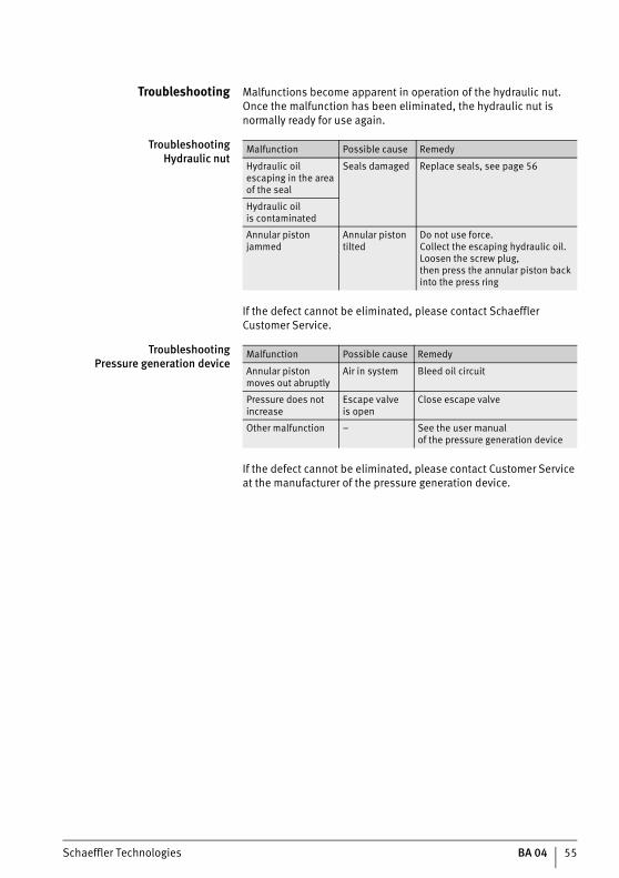
Troubleshooting Malfunctions become apparent in operation of the hydraulic nut. Once the malfunction has been eliminated, the hydraulic nut is normally ready for use again.
TroubleshootingHydraulic nut
If the defect cannot be eliminated, please contact Schaeffler Customer Service.
TroubleshootingPressure generation device
If the defect cannot be eliminated, please contact Customer Service at the manufacturer of the pressure generation device.
Malfunction Possible cause Remedy
Hydraulic oil escaping in the area of the seal
Seals damaged Replace seals, see page 56
Hydraulic oilis contaminated
Annular piston jammed
Annular piston tilted
Do not use force.Collect the escaping hydraulic oil.Loosen the screw plug,then press the annular piston backinto the press ring
Malfunction Possible cause Remedy
Annular piston moves out abruptly
Air in system Bleed oil circuit
Pressure does not increase
Escape valveis open
Close escape valve
Other malfunction – See the user manualof the pressure generation device

56 BA 04 Schaeffler Technologies
Hydraulic nuts HYD-NUT..-E, HYDNUT..-E-INCH
Maintenance The hydraulic nut must be checked before every use.
NOTICE Damage to the hydraulic nut in the case of defective maintenance.If seals are damaged, contamination can reach the pressure chamber of the hydraulic nut.If oil is lost, replace the seals immediately.
Maintenance plan The maintenance items are stated in the maintenance plan,see tables.
Before every use
After every use
Every 2 years
As necessary
Ordering the seal Order suitable replacement seals before replacement is carried out. The ordering designation of the seal set is the designationof the hydraulic nut, plus .SEAL. The seal set for the hydraulic nut HYTNUT100-E has the following ordering designation.
Ordering designation HYDNUT100-E.SEAL
Replacing the seal Before replacing the seals, check whether suitable replacement seals are available.The replacement of seals comprises the following operations:■ Dismount the annular piston.■ Dismount the seals.■ Clean the components.■ Mount the seals.■ Mount the annular piston.
Subassembly Activity
Hydraulic nut ■ Visual inspection –check for wear and damage
Subassembly Activity
Press ring and annular piston ■ Clean using cold cleaner or paraffin oil■ Apply oil (rust protection)
Subassembly Activity
Seal ■ Replacement
Subassembly Activity
Seal ■ Replace if oil is lost
Schaeffler Technologies BA 04 57
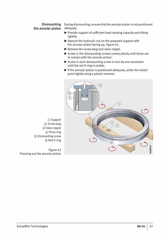
Dismountingthe annular piston
During dismounting, ensure that the annular piston is not positioned obliquely. Provide support of sufficient load carrying capacity and tilting
rigidity. Deposit the hydraulic nut on the prepared support with
the annular piston facing up, Figure 41. Remove the screw plug and valve nipple. Screw in the dismounting screws consecutively until these are
in contact with the annular piston. Screw in each dismounting screw in turn by one revolution
until the red O ring is visible. If the annular piston is positioned obliquely, strike the raised
point lightly using a plastic hammer.
� Support� Screw plug
� Valve nipple� Press ring
� Dismounting screw� Red O ring
Figure 41Pressing out the annular piston 00
0B04
CF00
0B04
CF

58 BA 04 Schaeffler Technologies
Hydraulic nuts HYD-NUT..-E, HYDNUT..-E-INCH
Note Starting from HYDNUT400, eye bolts can be screwed into the annular piston and a crane can be used to lift and transport the dismounted annular piston. Remove the annular piston, Figure 42.
Dismounting the seals When removing the seals, ensure that the seal slots remain undamaged. For dismounting, use a soft tool made from wood or plastic. Lever the seals out of the seal slots, Figure 43.
� Annular piston� Eye bolt
Figure 42Removing the annular piston 00
0B04
C600
0B04
C6
� Seal� Seal slot
� Wooden or plastic tool
Figure 43Dismounting the seals 00
0B04
BD00
0B04
BD
Schaeffler Technologies BA 04 59
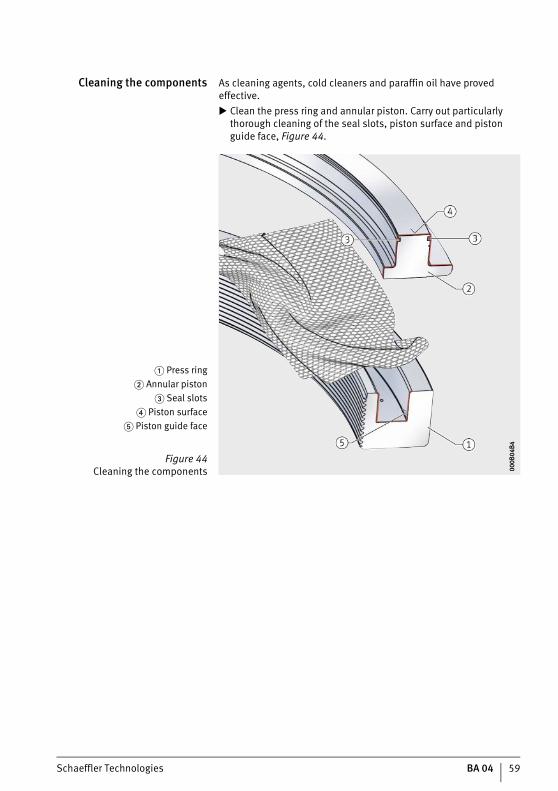
Cleaning the components As cleaning agents, cold cleaners and paraffin oil have proved effective. Clean the press ring and annular piston. Carry out particularly
thorough cleaning of the seal slots, piston surface and piston guide face, Figure 44.
� Press ring� Annular piston
� Seal slots� Piston surface
� Piston guide face
Figure 44Cleaning the components 00
0B04
B400
0B04
B4

60 BA 04 Schaeffler Technologies
Hydraulic nuts HYD-NUT..-E, HYDNUT..-E-INCH
Mounting the seals During mounting, ensure that the seals remain undamaged. Oil both seal slots using hydraulic oil, Figure 45.
Insert new seals in the annular piston, Figure 46.
� Seal slot� Hydraulic oil
Figure 45Oiling the seal slots 00
0B04
AB00
0B04
AB
� Seal� Piston guide face
Figure 46Mounting the seals 00
0B04
A200
0B04
A2
Schaeffler Technologies BA 04 61
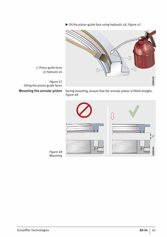
Oil the piston guide face using hydraulic oil, Figure 47.
Mounting the annular piston During mounting, ensure that the annular piston is fitted straight, Figure 48.
� Piston guide faces� Hydraulic oil
Figure 47Oiling the piston guide faces 00
0B04
9800
0B04
98Figure 48Mounting 00
0B04
8600
0B04
86
62 BA 04 Schaeffler Technologies
Hydraulic nuts HYD-NUT..-E, HYDNUT..-E-INCH
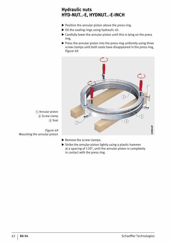
Position the annular piston above the press ring. Oil the sealing rings using hydraulic oil. Carefully lower the annular piston until this is lying on the press
ring. Press the annular piston into the press ring uniformly using three
screw clamps until both seals have disappeared in the press ring, Figure 49.
Remove the screw clamps. Strike the annular piston lightly using a plastic hammer
at a spacing of 120°, until the annular piston is completelyin contact with the press ring.
� Annular piston� Screw clamp
� Seal
Figure 49Mounting the annular piston 00
0B04
8F00
0B04
8F

Schaeffler Technologies BA 04 63
Disposal A hydraulic nut can be returned to Schaeffler for disposal.
CAUTION Risk of injury due to skin contact with hydraulic oil.Wear gloves when dismantling the hydraulic nut.
After dismounting, the press ring and annular piston can be disposed of together with other steel parts. The seals are madefrom plastic (PVC). Hydraulic oil must be collected and disposedof correctly or recycled. Aids such as oil-soaked cleaning clothsmust be disposed of correctly.
Regulations Disposal must be carried out in accordance with locally applicable regulations.
64 BA 04 Schaeffler Technologies
Hydraulic nuts HYD-NUT..-E, HYDNUT..-E-INCH
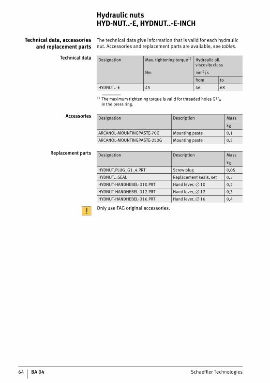
Technical data, accessoriesand replacement parts
The technical data give information that is valid for each hydraulic nut. Accessories and replacement parts are available, see tables.
Technical data
1) The maximum tightening torque is valid for threaded holes G1/4in the press ring.
Accessories
Replacement parts
Only use FAG original accessories.
Designation Max. tightening torque1) Hydraulic oil,viscosity class
Nm mm2/s
from to
HYDNUT..-E 45 46 68
Designation Description Mass
kg
ARCANOL-MOUNTINGPASTE-70G Mounting paste 0,1
ARCANOL-MOUNTINGPASTE-250G Mounting paste 0,3
Designation Description Mass
kg
HYDNUT.PLUG_G1_4.PRT Screw plug 0,05
HYDNUT...SEAL Replacement seals, set 0,2
HYDNUT-HANDHEBEL-D10.PRT Hand lever, � 10 0,2
HYDNUT-HANDHEBEL-D12.PRT Hand lever, � 12 0,3
HYDNUT-HANDHEBEL-D16.PRT Hand lever, � 16 0,4
Schaeffler Technologies BA 04 65
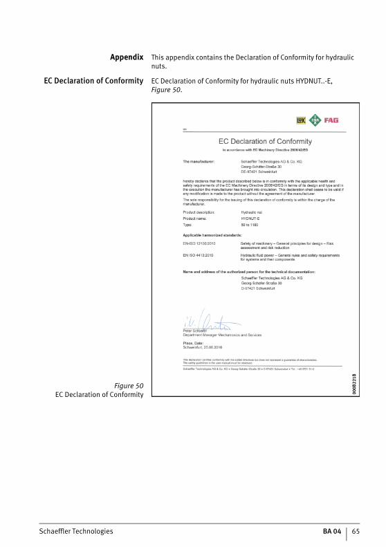
Appendix This appendix contains the Declaration of Conformity for hydraulic nuts.
EC Declaration of Conformity EC Declaration of Conformity for hydraulic nuts HYDNUT..-E, Figure 50.
Figure 50EC Declaration of Conformity 00
0B22
1B00
0B22
1B

Schaeffler Technologies AG & Co. KG
Georg-Schäfer-Straße 3097421 SchweinfurtGermanyInternet www.schaeffler.de/enE-Mail [email protected]
In Germany:Phone 0180 5003872Fax 0180 5003873
Aus anderen Ländern:Phone +49 9721 91-0Fax +49 9721 91-3435
Every care has been taken to ensure the
correctness of the information contained
in this publication but no liability can
be accepted for any errors or omissions.
We reserve the right to make technical
changes.
© Schaeffler Technologies AG & Co. KG
Issued: 2018, April
This publication or parts thereof may not
be reproduced without our permission.
BA 04 GB-DBA 0
4 /
03 /
GB-
D /
201
804
/ pd
f onl
y