hydraulic oil tank
TRANSCRIPT
Lecture 02
Fluid Storage
Reservoirs
Professor Dr.M.F.Khalil
2
Reservoir
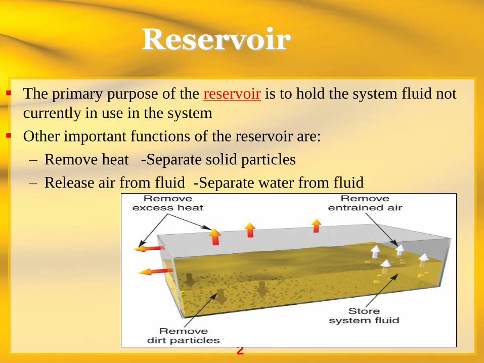
The primary purpose of the reservoir is to hold the system fluid not
currently in use in the system
Other important functions of the reservoir are:
– Remove heat -Separate solid particles
– Release air from fluid -Separate water from fluid
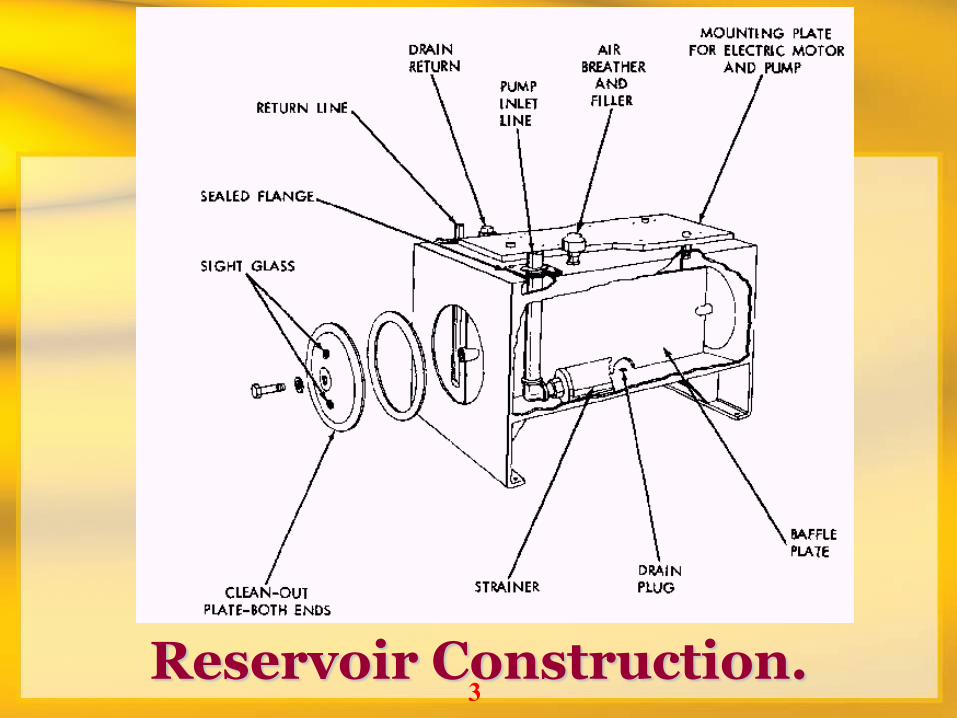
3 Reservoir Construction.
4
Reservoir
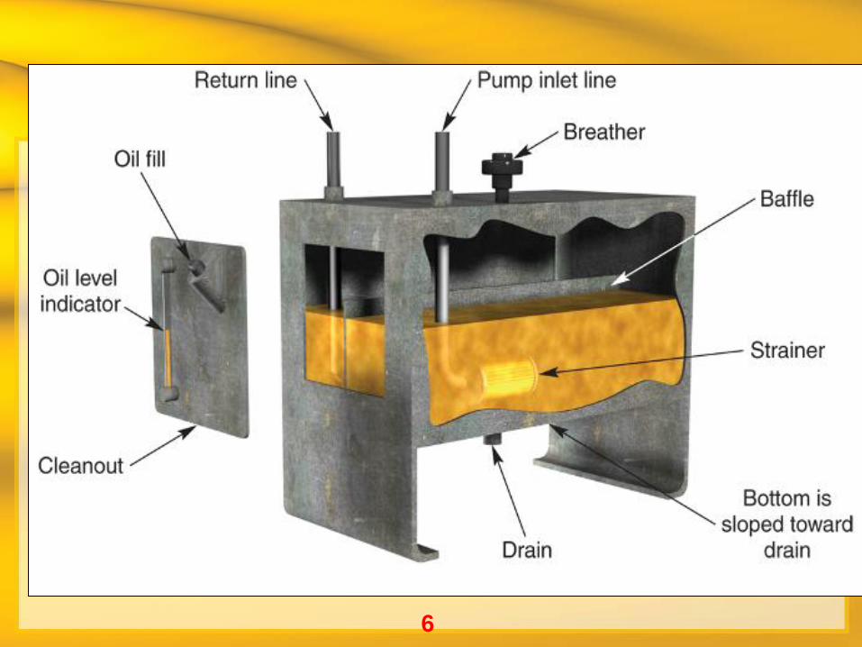
The typical hydraulic system reservoir is a rectangular, covered steel tank
The tank is typically fitted with:
– Pump inlet line
– System fluid return line
– Drain line
– Filler cap
– Air breather
– Fluid-level indicator
5
Reservoir
Baffles are used in the interior of reservoirs to
direct flow to maximize the distance the fluid
must travel between the return line and the
pump inlet line
– Slows the movement of the fluid
– Increases cooling
– Increases separation of solid particles, air, and water
6
7
Reservoir
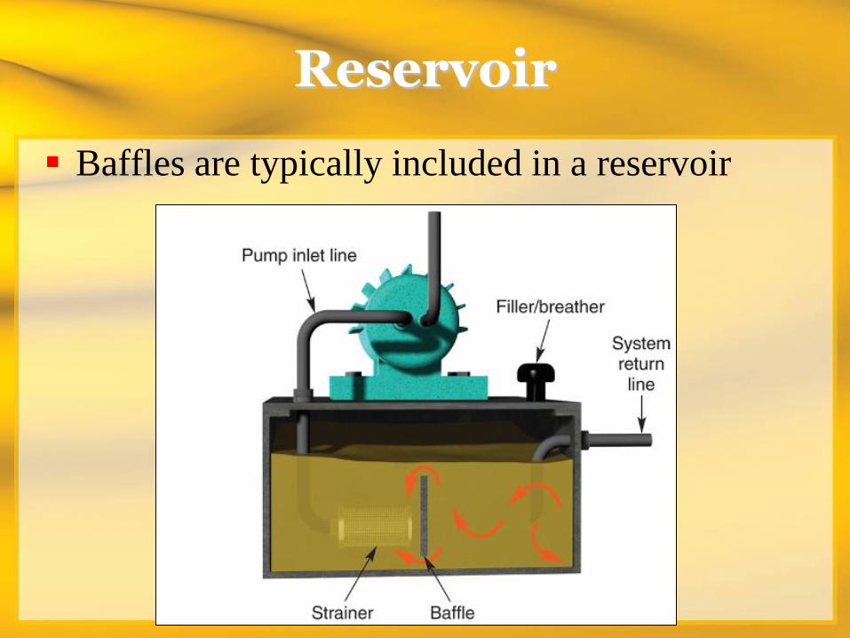
Baffles are typically included in a reservoir
8
Reservoir
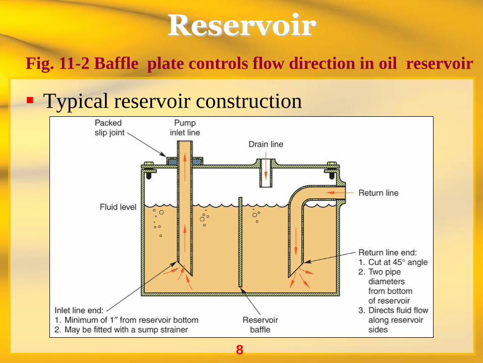
Typical reservoir construction
Fig. 11-2 Baffle plate controls flow direction in oil reservoir
9
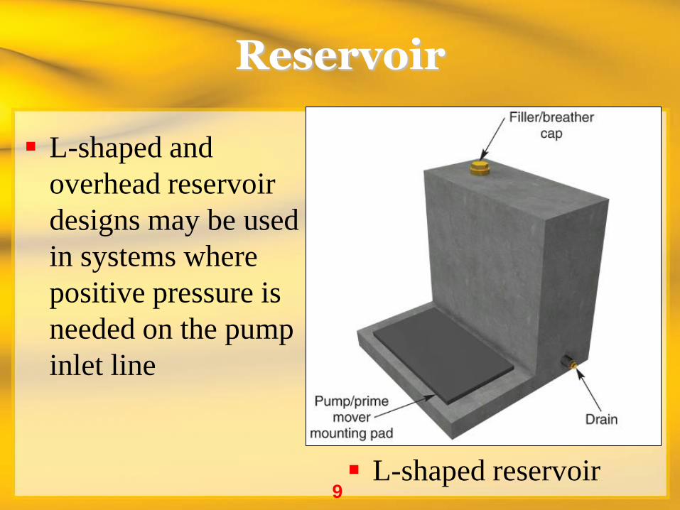
Reservoir
L-shaped and
overhead reservoir
designs may be used
in systems where
positive pressure is
needed on the pump
inlet line
L-shaped reservoir
10
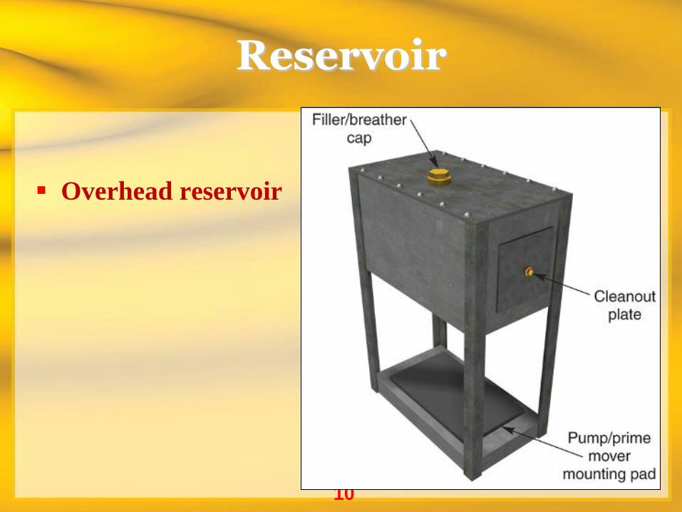
Reservoir
Overhead reservoir
11
Reservoir
In special situations, the system reservoir
may be:
– Cavities in large machines (Crank case in I.C.E)
– Gear cases in mobile equipment
12
Reservoir
As a general rule, the capacity of the reservoir
should be three times the rated flow of the
pump
– Fixed installations may be higher
– Mobile applications, where weight and space are
factors, may be less
Reservoir Size
Most system specifications call for the reservoir to contain
three times the pump flow rate. If the pump operates at 5 gpm,
then the reservoir capacity should be 15 gallons.
The mobile equipment industry tends to use a 1 to 1 ratio; a 5
gpm pump would require a 5 gallon reservoir. Other
requirements vary according to application.
It might be safe to say, then, that an oversized reservoir might
be on the order of 10 to 1-10 gallons of fluid for each gpm of
output.
Another heat exchange function that might take place in the
reservoir is to heat the fluid rather than cool it. This situation could
arise during the startup of a system that has been exposed to low
temperatures for am extended time. The cold fluid may not be pump
able, so it may be necessary to heat it to lower its viscosity. This is
usually accomplished by electrical heating elements immersed in
the fluid. Steam or hot water pipes are sometimes run through the
tank.
If electric heaters are used, care must be taken not to "cook" the
fluid that contacts the heating elements. This results in degradation
of the fluid and the creation of a coating of burned fluid on the
elements that severely reduces their heating efficiency. As a rule of
thumb, the heat output of in tank heating elements should not
exceed 3 watts per square inch of heating element surface.
Sedimentation
A reservoir acts as a filter when solid particles are allowed to settle to
the bottom as the fluid passes through. Unfortunately, not all of the
particles will settle out of the fluid. For settling to occur, the force of
gravity must overcome buoyant forces and viscous drag. Relatively
large, dense particles will tend to settle out fairly rapidly, while small
particles (smaller than 10 microns, say) may never settle out,
especially in a high-viscosity fluid.
The longer the dwell time of the fluid in the reservoir, the more
opportunity there is for particle drop-out. This constitutes another
factor favoring oversized reservoirs, although one might argue-and
validity so-that good filtration (internal and external) should remove
the large particles before they get to the reservoir. It can also be
pointed out that an off-line filter loop will do far more to clean the fluid
in the reservoir than sedimentation could ever do.
Deaeration
Reservoirs work at atmospheric pressure provide an opportunity for deaeration,
the release of air that may have been trapped in the fluid for any reason. Air in
fluids may take three different forms:
• Dissolved- Entrained - Free
Most hydraulic oils will contain about 10 percent air by volume under atmospheric
pressure. This dissolved air is contained in the "empty spaces" between the fluid
molecules, and does not increase the volume of the fluid.
As we exceed the amount of air that can be dissolved in a fluid, we begin to
encounter entrained air. We see this in the form of bubbles which are 0.001 to
0.030 in (25 to 750 m) in diameter. Fluids with entrained air tend to look cloudy
or foamy. Generally, entrained air is attempting to get out of the fluid.
Free air is seen as large "globs" of air in the system. This condition is most
commonly found in cylinders, accumulators, and elevated points in the system
where the fluid velocity is low enough for entrained air bubbles to agglomerate
and form large air pockets.
Air in any form can have detrimental effects in the system. Fluid oxidation
requires oxygen-the presence of air in any form will suffice.
The advantage of using liquids instead of gases is lost with highly aerated
fluids. Fluid column stiffness is lost because the air in the fluid is
compressible, and, in fact, must be compressed before any other work
can be done. This causes system response to be slow and sponge.
Finally, aerated fluid causes pseudo-cavitation in pumps, valves, and so
on. This can cause severe damage and rapidly degrade the components
to absolute uselessness.
In a reservoir that is open to atmospheric pressure, as are most industrial
reservoirs, we can remove only the entrained and free air, even during the
very long dwell times or even when the system is shut down. If the
reservoir is pressurized, the release of air will be restricted by the Henry-Dalton Law: the amount of air that can be dissolved in a fluid is directly proportional to the air pressure above the fluid.
Creating a vacuum in the reservoir will significantly accelerate the release
of free and entrained air and promote the dissolution of the dissolved air.
An advantage of this practice is that the fluid can act as an air "sponge,"
readily absorbing any air that might be bleeding into the system or
introduced by bad maintenance practices. However, it is more expensive
and troublesome than standard breathing reservoirs. Reservoir vacuum
could also be detrimental as far as pump suction is concerned and could
lead to pump cavitation.
A design that is sometimes seen, however, is a reservoir containing a
sloped screen through which the fluid flows as it moves from the return
line to the pump inlet line. Air bubbles tend to adhere to the screen and
thus be removed from the flow stream. Eventually, they agglomerate,
forming large bubbles that rise to the surface and dissipate. The most
effective arrangement seems to be number 100 to number 400 wire mesh
inclined about 20 degrees to the horizontal. Air removal efficiencies in
excess of 95 percent have been experienced, but again, dwell time is very
important, because the removal efficiency is dependent on the velocity of
the fluid as it passes through the screen.
Dehydration
During periods of system downtime, when the fluid is
standing in the reservoir, water in fluids that are less
dense than water will tend to separate from the oil and
settle to the bottom where it can be drained off. This
separation will occur only if the water and oil have not
been emulsified.
As with the separation of air from the oil, the
separation of water is not instantaneous. Little
separation is likely to occur as long as the fluid is
moving through the reservoir unless very large amounts
of water are present.
Alternative Devices
Some of the functions we have discussed are performed fairly efficiently
by the reservoir. It is often found, however, that other, dedicated devices
can perform these functions more efficiently than the reservoir.
While there is no question that a great deal of dirt ends up upon the
bottom of the tank (all you need to do is look), good filters perform this
function far more efficiently.
Water removal is another function that can be performed more efficiently
by devices specifically designed for that purpose. A properly designed
water separator removes water from the oil continuously, while the
system is operating. It does not require quiescent fluid to be effective,
and the water is removed in an active rather than passive operation.
Heat exchangers, while viewed by some as unnecessary when large
reservoirs are used, can be utilized very effectively. In some cases, the
bulk or weight of an oversized reservoir is undesirable. The thermal
demands of the system may require a heat exchanger in some cases.
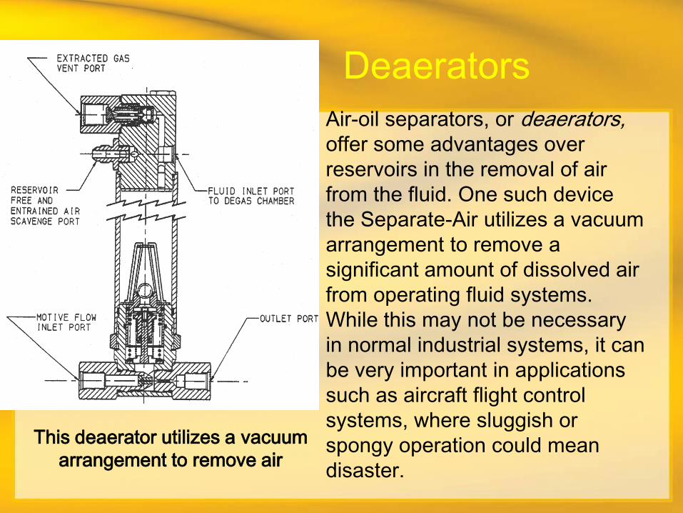
Air-oil separators, or deaerators, offer some advantages over
reservoirs in the removal of air
from the fluid. One such device
the Separate-Air utilizes a vacuum
arrangement to remove a
significant amount of dissolved air
from operating fluid systems.
While this may not be necessary
in normal industrial systems, it can
be very important in applications
such as aircraft flight control
systems, where sluggish or
spongy operation could mean
disaster.
This deaerator utilizes a vacuum
arrangement to remove air
Deaerators
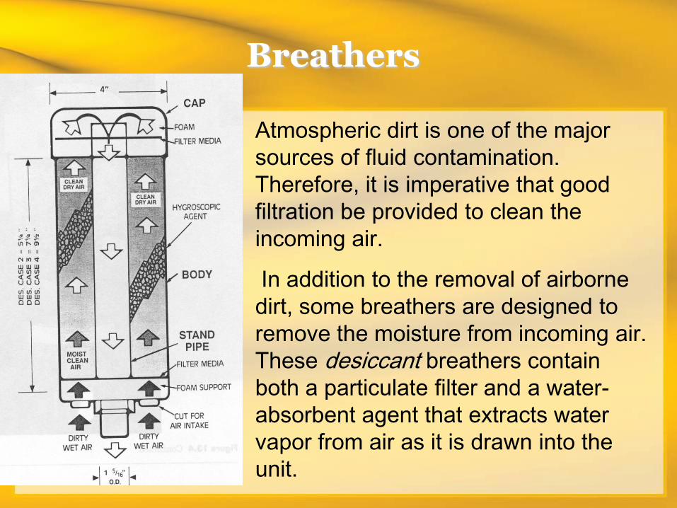
Breathers
Atmospheric dirt is one of the major
sources of fluid contamination.
Therefore, it is imperative that good
filtration be provided to clean the
incoming air.
In addition to the removal of airborne
dirt, some breathers are designed to
remove the moisture from incoming air.
These desiccant breathers contain
both a particulate filter and a water-
absorbent agent that extracts water
vapor from air as it is drawn into the
unit.
An alternative method of preventing the ingression of dirt and moisture
is to prevent the inhaling of atmospheric air. This can be done with a
so-called pressurized breather, which contains a vacuum breaker to
allow an initial influx of air when the system is first started up and fluid
is pulled from the reservoir. In subsequent operation, as fluid returns to
the tank, a relief valve prevents the air from being expelled from the
tank. Rather, it is compressed and will be exhausted only if the relief
valve setting (which can be from 3 to as much as 25 psig) is exceeded.
Caution must be used when adding a pressurized breather to an
existing reservoir to ensure that the tank structure can withstand the
internal pressure. Otherwise, a good idea can go very sour.
The ideal situation, of course, would be to use a completely sealed
reservoir that has no communication with the environment.
Unfortunately, this is seldom done because of the expense and weight
involved in providing sufficient strength to withstand the internal
pressures that might result.
Pump Inlet and Return Lines
The locations of the pump inlet line and the system return line can be critical in
the ability of the tank to perform all the jobs that are thrust upon it. Therefore,
we should arrange the inlet and return lines to provide the longest and most
tortuous path possible. They should be at opposite ends of the tank or on the
same end but on the opposite sides of a longitudinal baffle.
The pump inlet line must be near, but never on, the bottom of the tank. If it
were on the bottom, dirt that has settled out of the fluid might be picked up
when the pump starts.
Return lines must always be below the surface of the fluid, preferably extending
to near the bottom of the tank. The addition of a diffuser on the end of the
return line will promote the release of air and generate mixing of the returning
fluid with that in the tank to aid in heat transfer.
Very often (but not always), the top of the reservoir will be a heavy cover that is
bolted to the side walls is very common for the pump and drive motor, some
valves, the filters, and so on, to be mounted on this cover. In other cases, it is
simply the lid. Whatever the case, it is important that a good gasket be provided
for the cover to prevent the entrance of atmospheric air. It is also important that
the cover be kept on the reservoir and bolted down securely to maintain the
integrity of that gasket. Otherwise, the door is opened for major contamination
problems.
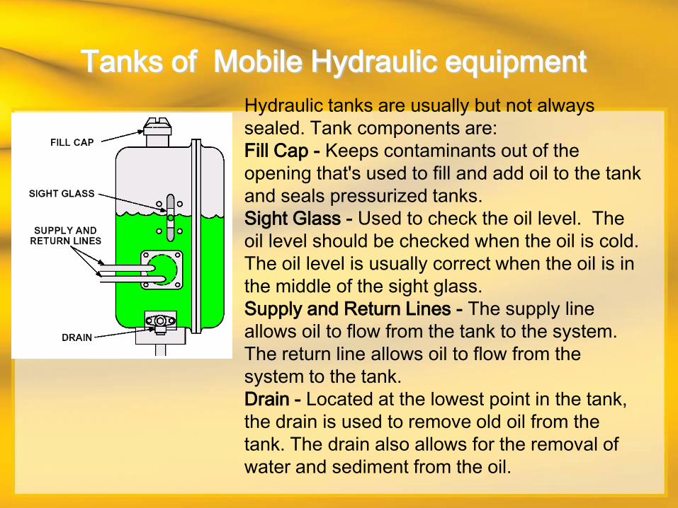
Tanks of Mobile Hydraulic equipment
Hydraulic tanks are usually but not always
sealed. Tank components are:
Fill Cap - Keeps contaminants out of the
opening that's used to fill and add oil to the tank
and seals pressurized tanks.
Sight Glass - Used to check the oil level. The
oil level should be checked when the oil is cold.
The oil level is usually correct when the oil is in
the middle of the sight glass.
Supply and Return Lines - The supply line
allows oil to flow from the tank to the system.
The return line allows oil to flow from the
system to the tank.
Drain - Located at the lowest point in the tank,
the drain is used to remove old oil from the
tank. The drain also allows for the removal of
water and sediment from the oil.
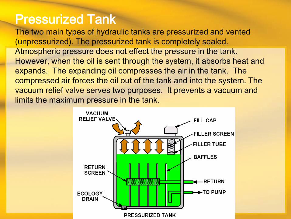
Pressurized Tank The two main types of hydraulic tanks are pressurized and vented
(unpressurized). The pressurized tank is completely sealed.
Atmospheric pressure does not effect the pressure in the tank.
However, when the oil is sent through the system, it absorbs heat and
expands. The expanding oil compresses the air in the tank. The
compressed air forces the oil out of the tank and into the system. The
vacuum relief valve serves two purposes. It prevents a vacuum and
limits the maximum pressure in the tank.
The vacuum relief valve prevents a vacuum by opening and allowing
air to enter the tank when the tank pressure drops to 3.45 kPa (.5
psi). When pressure in the tank reaches the vacuum relief valve
pressure setting, the valve opens and vents compressed air to the
atmosphere. The vacuum relief valve pressure setting may vary from
70 kPa (10 psi) to 207 kPa (30 psi).
Other tank components are:
Filler screen - keeps large contaminants from entering the tank when
the fill cap is removed.
Filler tube - allows the tank to be filled to the correct level, but not
over filled.
Baffles - prevents the return oil from flowing directly to the tank outlet,
allowing time for bubbles in the return oil to rise to the top. Also,
prevents the oil from sloshing which helps reduce forming of the oil.
Ecology Drain - used to prevent accidental spills when removing
water and sediment from the tank.
Return screen - prevents larger particles from entering the tank, but
does not provide fine filtering,
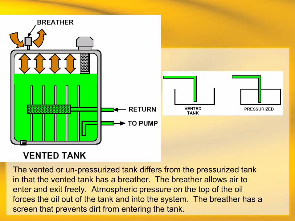
Vented Tank The vented or un-pressurized tank differs from the pressurized tank
in that the vented tank has a breather. The breather allows air to
enter and exit freely. Atmospheric pressure on the top of the oil
forces the oil out of the tank and into the system. The breather has a
screen that prevents dirt from entering the tank.