hydraulic planetary gear winches6-7 - ramsey...
TRANSCRIPT


2 3

ramsey.com2 3
Table of Contents
Hydraulic Worm Gear Winches ............................................................................................................................4-5Hydraulic Planetary Gear Winches .......................................................................................................................6-7Heavy Duty Electric Worm Gear Winches .............................................................................................................8-9Extended Shaft Winches .................................................................................................................................10-11Worm Gear Speed Reducers ...........................................................................................................................12-13Options for Ramsey Hydraulic Worm Gear Winches and Planetary Hydraulic Winches ......................................14-15
WARNINGWinches are not to be used to lift, support or otherwise transport personnel. A minimum of five (5) wraps of cable around the drum is necessary to support the rated load. Cable clamp is not designed to hold the load.
Limited Warranty Excerpt
Ramsey Winch warrants each new winch and speed reducer to be free from defects in workmanship for a period of one (1) year from date of purchase. The obligation under this warranty, statutory or otherwise, is limited to the replacement or repair at our factory of such part or parts as shall appear to us upon inspection to be defective in materials and workmanship. Complete warranty statement packed with each item.
How to Select a Winch1. Determine the line pull required.
2. Determine the size (diameter) and length of cable required.
3. Where will the line load occur–on the first layer of cable on the drum barrel? The second? The third?
4. Select the proper winch model and determine the first layer rating required (all performance charts in this brochure are based on the first layer line pull ratings. All winches are rated based on first layer).
EXAMPLE: Customer A has an application that requires a 5,000 lbs. line pull and have selected 80 ft. (24.3m) of 3/8 inch (9mm) diameter cable as the optimum length. This application would require a low mount hydraulic winch.
Referring to the performance data for low mount hydraulic winches on page 5, 80 ft. of 3/8 cable will build up to three layers on a model H-200 winch and the winch provides 5,700 lbs. (2,580 kgs) maximum allowable line pull on the third layer. The line speed on this layer would be 17.5 ft./min. at the maximum hydraulic system flow of 15 GPM. Line speed on the first layer would be 12.6 ft./min. Also, note that the required hydraulic system pressure is 1,550 PSI minimum.
Customer A would therefore select our Model H-200 winch with 8,000 lbs. first layer line pull rating as the best choice.
*For performance using wire sizes other than the recommended size, contact the factory.
4 5
2.50 63,5
2.50
63,5
5.62 142,7
4.56 115,8
3.62 92,0
D
2.0652,3A
B
.69 17,5
7.25 184,2
3.50 88,9
DIA.
DIA.
1.37 34,9 6.91
175,5
3.72 94,4
6.22 158,0
C
2.5063,5
.256,4
5.37136,4
2.5063,5
.5012,7
2.1254,0 3.51
89,136.0
914,4
WINCHMODEL
H-200
HY-200
AINCHES
MMINCHES
MM
B
MMINCHES
C
MMINCHES
D
7.78197,6
5.28134,1
11.31287,3
6.31160,3
8.94227,0
11.44290,5
13.12333,3
8.12206,3
DIMENSIONS SHOWN ARE INCHES OVER MILLIMETERS
POSITION
CLUTCH ATDIS-ENGAGED
55,62.19
53,92.12
CLUTCH AT
POSITIONENGAGED 31,7
1.25
H-800 Series – Dimensions
DIMENSIONS SHOWN ARE INCHES OVER MILLIMETERS
DIA.
ENGAGEDCLUTCH DIS-ENGAGED
CLUTCH
IN THIS DIRECTIONHANDLE SPRING LOADED
CLUTCH HOUSING CAN BEROTATED 180˚ FORCUSTOMER INSTALLATION
1-1/16-20 O-RING PORT2-PLACES 180˚ APART
1.2531,7
7.75196,8
6.87174,6
F
ø 12.13308,0
B
2.4061,0
E
2.5063,5
2.5063,5D
A2.8472,1
8.40213,3
C
5.15130,8
2.2557,1
2.2557,1
.5012,7
3.0076,2
14.00355,6
9.18233,1
6.18156,9
2.1354,0
4.00101,6
10.38263,6
.9423,8
11.20284,4
6.54166,1
8.36212,3
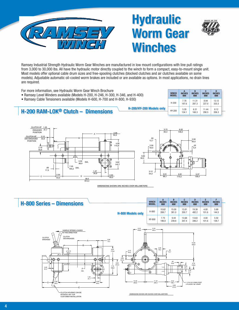
Hydraulic Worm Gear Winches
Ramsey Industrial Strength Hydraulic Worm Gear Winches are manufactured in low mount configurations with line pull ratings from 3,000 to 30,000 lbs. All have the hydraulic motor directly coupled to the winch to form a compact, easy-to-mount single unit. Most models offer optional cable drum sizes and free-spooling clutches (blocked clutches and air clutches available on some models). Adjustable automatic oil-cooled worm brakes are included or are available as options. In most applications, no drain lines are required.
For more information, see Hydraulic Worm Gear Winch Brochure• Ramsey Level Winders available (Models H-200, H-246, H-300, H-346, and H-400)• Ramsey Cable Tensioners available (Models H-600, H-700 and H-800, H-930)
H-200/HY-200 Models onlyH-200 RAM-LOK® Clutch – Dimensions
H-800 Models only
WINCHMODEL
H-200
HY-200
AINCHES
MM
7.78197.6
5.28134.1
BINCHES
MM
11.31287.3
6.31160.3
CINCHES
MM
8.94227.0
11.44290.5
DINCHES
MM
13.12333.3
8.12206.3
WINCHMODEL
H-800
HY-800
AINCHES
MM
10.62269.7
7.75196.8
BINCHES
MM
15.00381.0
9.44239.8
CINCHES
MM
13.81350.7
13.68347.4
DINCHES
MM
19.38492.2
13.63346.2
EINCHES
MM
4.00101.6
4.00101.6
FINCHES
MM
5.69144.5
5.50139.7

ramsey.com4 5
Performance Data
* Last layer does not conform to SAE Standard J706.A-Standard rating listed. Higher SAE J706 ratings available–contact factory.
MinimumSystem
Pressurefor
RatedPull(PSI)
750
750
1000
1600
1800
1700
2500
2375
1750
2000
2100
2800
3000
2750
2750
2200
2500
MaximumSystem
Flow(GPM)
15
15
15
15
15
15
15
15
15
15
15
23
23
25
30
30
35
WormGearRatio
38:1
38:1
38:1
60:1
46:1
30:1
30:1
34:1
60:1
46:1
30:1
29:1
29:1
40:1
35:1
40:1
41:1
LinePull
(LBS)(KGS)
30001350
30001350
40001810
80003620
80003620
80003620
80003620
80003620
90004070
90004070
10,0004540
10,0004540
10,0004540
12,0005430
15,0006790
20,0009060
30,00013,590
CableCap.(Ft)(M)
103.0
154.0
154.0
258.0154.0
258.0154.0
258.0154.0
258.0154.0
258.0154.0
258.0154.0
258.0154.0
206.0154.0
257.0
206.0
206.0154.0309.0
206.035
10.0
3510.0206.0
257.0
LineSpeed(FPM)(MPM)
165.0
165.0
175.1
123.8
165.0
329.7
329.7
288.5
123.8
165.0
329.7
3010.0
3310.5
257.6
278.2
185.4185.5
133.9
Line Pull
(LBS)KGS)
26001170
26001170
33001490
67003030
67003030
67003030
67003030
67003030
75003390
75003390
81003670
82003710
83003760
98004430
12,3005570
16,6007520
24,50011,090
CableCap.(Ft)(M)
206.0
4012.0
309.0
6018.0309.0
6018.0309.0
6018.0309.0
6018.0309.0
6018.0309.0
6018.0309.0
6018.0309.0
5015.0309.0
5516.0
4513.0
5516.040
12.065
19.0
5015.075
22.0
7522.045
13.0
6519.0
LineSpeed(FPM)(MPM)
195.8
195.8
206.0
154.5
195.9
3811.5
3811.5
3410.3
154.5
195.9
3811.5
4012.0
4012.3
319.4
3310.0
226.6216.3
175.3
Line Pull
(LBS)KGS)
2200900
2200900
29001310
57002580
57002580
56002520
56002520
57002610
64002890
64002890
69003120
69003120
71003210
83003750
10,5004750
14,2006430
20,7009370
CableCap.(Ft)(M)
3510.0
6519.0
5516.0
9530.055
16.0
9530.055
16.0
9530.055
16.0
9530.055
16.0
9530.055
16.0
9530.055
16.0
9530.055
16.0
8525.055
16.0
9027.0
7021.0
9027.065
19.011033.0
8525.012538.0
12538.075
22.0
10531.0
LineSpeed(FPM)(MPM)
216.3
216.3
236.9
175.3
226.6
4513.7
4513.7
3911.8
175.3
226.6
4413.3
5316.0
4714.5
3711.2
3811.5
267.9257.6
206.0
Line Pull
(LBS)KGS)
2000900
2000900
25001130
50002260
50002260
50002260
50002260
50002260
56002530
56002530
60002710
62002800
72003260
91004120
12,4005610
18,0008150
CableCap.(Ft)(M)
5015.0
9528.0
8024.0
14043.075
22.0
14043.075
22.0
14043.075
22.0
14043.075
22.0
14043.075
22.0
14043.075
22.0
14043.075
22.0
13039.0
10531.0
13039.095
28.016550.0
12538.018556.0
1805411033
15547.0
LineSpeed(FPM)(MPM)
247.2
247.2
267.9
206.0
267.9
5115.5
5115.5
4413.3
206.0
267.9
5316.0
5416.0
4212.7
4413.3
298.8288.5
247.2
Line Pull
(LBS)KGS)
1800810
1800810
63002850
81003660
11,0004980
CableCap.(Ft)(M)
7021.0
12538.0
18054.013539.0225.068.0
17051.025076.0
24072.015045.0
LineSpeed(FPM)(MPM)
278.2
278.2
4814.5
5015.2
3310.0319.4
1st Layer 2nd Layer 3rd Layer 4th Layer 5th Layer
WinchModel
H-7
HX-7
H-8B
H-200
HY-200
H-246
HY-246
HD-200
HDY-200
HD-200
HDY-200
HD-234
HDY-234
H-300
HY-300
H-346
HY-346
HDG-350
HDGY-350
H-400
HG-400
HY-400HGY-400
H-600
HY-600
HX-600
H-700
HX-700
H-800
HY-800
H-930
*
*
*
A A
A*
A*
A*
A*
A*
A*
A*
A*
A*
Recom-mended
Wire RopeSize
(INCH)(MM)
1/46
1/46
5/168
3/89
3/89
3/89
3/89
3/89
3/89
3/89
7/1611
7/1611
7/1611
1/213
9/1614
5/816
3/419
WinchRating(LBS)
3000
3000
8000
8000
8000
8000
8000
8000
9000
9000
10,000
10,000
10,000
12,000
15,000
20,000
30,000
Hydraulic Worm Gear Selection Chart

*
(2-PLACES EACH SIDE OF GEAR HOUSING END BEARING)1/2-13UNC X .50 (INCHES) DEEP TAPPED HOLE
7/8-14 SAE PORT(2-PLACES)
1/2-13UNC X .75 (INCHES) DEEP TAPPED HOLE(2-PLACES EACH SIDE OF MOTOR END BEARING)
(TYP)
(TYP)
(TYP)
(TYP)
*
*
*
*
MOVE TIE PLATES TO FEETFOR SIDE MOUNT INSTALLATIONS,
2.21 [56.1]
ø 8.25 [209.6] .56
[14.3]
8.38 [212.7]
2.25 [57.2]
4.19 [106.4]
3.79[96.3]
7.17 [182.1]ø.50
[ø12.7]
1.25 [31.7] .50
[12.7]
2.21 [56.1]
4.25 [108.0]
F
EDC
B
A
CABLEANCHOR
4.92 [125.0]
8.46 [214.9]
DRUMCL
BARREL
ø 3.94 [100.0]
FLANGE
8.38 [212.9]
9.36 [237.7]4.68
[118.9]
1.12 [28.4]
1.12 [28.4]
NOTES:
1. DIMENSIONS SHOWN ARE INCHES OVER MILLIMETERS.
2. WINCH MOUNTING CAPSCREWS MUST MEET OR EXCEED SAE GRADE 5 SPECIFICATION.
3. THESE HOLE LOCATIONS MUST BE HELD WITHIN ±.03 (0.8mm)
OF TRUE POSITION. RECOMMENDED MOUNTING HOLE DIAMETER IS .53 (13.5mm).
4. "A" ROTATION SHOWN.
CLUTCH DISENGAGED POSITION
CLUTCH ENGAGED POSITION
1/2-13UNC X .75 (INCHES) DEEP TAPPED HOLE
(4-PLACES EACH END BEARING)
6 7
DIMENSIONS SHOWN ARE INCHES OVER MILLIMETERSWINCH MOUNTING CAPSCREWS MUST MEET OR EXCEED SAE GRADE 5 SPECIFICATION
*NOTE: THESE HOLE LOCATIONS MUST BE HELD WITHIN .03” (0.8 MM) OF TRUE POSITION. RECOMMENDED MOUNTING HOLE DIAMETER IS .53” (13.5 MM).
HD-P 8,000 – Dimensions
Hydraulic Planetary Gear Winches
RPH 50,000 – Dimensions
DIMENSIONS SHOWN ARE INCHES OVER MILLIMETERS
264,310.41
20.25514,3
101,64.00
446,017.56
223,08.78
PORT LOCATIONPNEUMATIC
12,7.50
68,32.69
1.5639,6
STATIC LOADHOLDING BRAKE
A
(9.6 CU IN MOTOR)238,89.40
63,52.50
A
78,5
3.09
90,4
3.56
DRUM CL
261,9
523,720.62
10.31
63,52.50
177,87.00
DIA.
(TYP. 4 PLACES EACH SIDE).81 (20,6 mm) DIA. THRU
184,27.25
368,314.50
7,4.29
T
SM
RA
CWYE
I CH O
A
KO
ULS
VIEW FOR TRUEORIENTATION OF PORT.
ENGAGED.) SEE END(CLUTCH IS SPRINGFOR DISENGAGING CLUTCH.PORT (100 TO 120 PSI)1/8-27NPT PRESSURE
1/8-27NPT PORT
589,023.19
DRUMFLANGE
DIA.406,416.00
RIGHT HAND SHOWN (LEFT HAND OPPOSITE)DIMENSIONS SHOWN ARE INCHES OVER MILLIMETERS
143,05.63
(TYP 4-PLACES)
158,76.25
DRUM
1090,942.95
12.25311,1
1.0626,9
22.5∞
Ramsey Industrial Hydraulic Planetary Winches are developed to meet a need for increased line speed for vehicle recovery and other industrial uses. Winches feature easy free spooling, single lubricant for all temperature ranges and light weight. For more information, see Planetary Hydraulic Winch Brochure.• Ramsey Level Winders available for HD-P 8,000 HD-P 10,000 & RPH 12,000• Ramsey Air Tensioners Available for RPH 15,000; RPH 20,000; RPH 25,000;
RPH 30,000; RPH 35,000; RPH 45,000 RPH 50,000 • Optional Air Shift Clutch available
A B C D E FWINCH INCHES INCHES INCHES INCHES INCHES INCHESMODEL MM MM MM MM MM MM
HD-P 8,000 9.75 12.25 8.87 14.60 13.28 27.89 STD. DRUM 247,7 311,2 225,3 370,9 337,4 708,3
HD-P 8,000 6.50 9.00 7.24 12.98 11.66 24.64 “Y” DRUM 165,1 228,6 184,0 329,6 296,2 625,8

ramsey.com6 7
Hydraulic Planetary Gear Selection Chart
Performance Data
* Last layer does not conform to SAE Standard J706.
HydraulicPressure Required
For Rated
Line Pull(PSI)
2500
2100
2500
2400
2500
3000
2800
2650
2800
3000
Hydraulic Flow
Required For
Rated Line
Speed(GPM)
15
15
15
15
15
15
15
15
25
25
GearRatio
5.1:1
5.1:1
5.1:1
7.7:1
25.53:1
25.53:1
31.89:1
31.89:1
51.35:1
51.35:1
LinePull
(LBS)(KGS)
80003620
10,0004530
12,005440
15,0006800
20,0009070
25,00011,340
30,00013,605
35,00015,909
45,00020,380
50,00022,670
CableCap.(Ft)(M)
257.0154.0
20 6.0154.0
206.0
3510.0
3510.0
3510.0
309.0
257.60
3510.0
309.0
LineSpeed(FPM)(MPM)
5015.2
329.8
329.7
257.6
267.9
278.3
195.7
154.6
237.0
237.0
Line Pull
(LBS)KGS)
68003080
83003760
10,0004530
12,6005710
16,9007660
20,8009430
25,20011,430
28,60013,000
37,70017,100
40,90018,550
CableCap.(Ft)(M)
5516.035
10.0
5015.0309.0
5015.0
7522.0
8525.0
7522.0
7522.0
6018.3
7522.0
6519.0
LineSpeed(FPM)(MPM)
5817.6
3811.6
3811.5
298.8
309.1
319.5
237.0
185.5
278.2
288.6
Line Pull
(LBS)KGS)
59002670
71003220
85003850
10,8004890
14,7006660
17,9008110
21,7009840
24,20011,000
32,40014690
34,60015,690
CableCap.(Ft)(M)
9027.060
18.0
8024.055
16.0
8024.0
12538.0
13541.0
12538.0
12036.0
10532.0
12538.0
11033.0
LineSpeed(FPM)(MPM)
6720.3
4413.4
4413.4
3410.3
3510.6
3611.1
267.9
216.4
329.8
3310.1
Line Pull
(LBS)KGS)
52002350
62002810
75003400
95004300
13,0005890
15,6007070
19,1008660
21,0009545
28,50012,920
30,00013,600
CableCap.(Ft)(M)
13039.085
25.0
11535.075
22.0
11535.0
18054.0
19559.0
18556.0
17553.0
15547.2
18054.0
16048.0
LineSpeed(FPM)(MPM)
7623.1
5115.0
5115.5
3911.8
3911.8
4111.8
298.8
237.0
3611.0
3811.7
Line Pull
(LBS)KGS)
47002120
66002990
85003850
11,6005260
13,9006300
17,0007700
18,5008390
25,30011,460
26,40011,970
CableCap.(Ft)(M)
17051.011534.0
16048.0
24073.0
26580.0
24574.0
23571.0
20060.0
24574.0
22066.0
LineSpeed(FPM)(MPM)
8425.5
5717.3
4413.4
4413.4
4614.0
3310.0
288.5
4012.2
4313.2
1st Layer 2nd Layer 3rd Layer 4th Layer 5th Layer
WinchModel
HD-P 8,000-S
HD-P 8,000-Y
HD-P 10,000-S
HD-P 10,000-Y
RPH 12,000
RPH 15,000
RPH 20,000
RPH 25,000
RPH 30,000
RPH 35,000
RPH 45,000
RPH 50,000
WinchRating(LBS)
8,000
10,000
12,000
15,000
20,000
25,000
30,000
35,000
45,000
50,000
Weightwithoutcable(LBS)(KGS)
82377635
87408237
11050
300136
375170
380172
486220
568 258
689313
689313
6th Layer
Line Pull
(LBS)KGS)
76003440
15,4006980
22,90010,380
CableCap.(Ft)(M)
31094.0
30091.0
31094.0
LineSpeed(FPM)(MPM)
4814.6
3610.9
4513.7
*
*
*
*
*
*
*
Recom-mended
Wire RopeSize
(INCH)(MM)
3/810
7/1611
7/1611
1/213
9/1614
5/816
5/816
3/419
3/419
7/822

7.05179,1
3.4788,2
2.8973,5
2.7870,7
2.5063,5
(TYP)
.256,4
.4912,6
(TYP)
CONNECT GROUND CABLE FROMNEGATIVE (-) BATTERY TERMINAL HERE
CONNECT POWER CABLE FROMPOSITIVE (+) BATTERY TERMINAL HERE
206,38.12
333,313.12
DINCHES
MM
WINCHMODEL
DC-200
DCY-200
INCHESMM
A
MMINCHES
B
MMINCHES
C
7.78197,6
5.28134,1
11.31287,3
6.31160,3
8.94227,0
11.44290,5
B
A
C D25.03
635,6
3.5088,9
34,9
17,5
2.50
63,5
.69
2.12
53,9
55,6
2.19
CLUTCH AT
POSITION
DIS-ENGAGED
1.37
DRUM
2.50
63,5
92,0
171,4
6.75
10.25260,3
115,8
3.62
4.56
3.7294,5
188,97.44
10.77273,6
914,4
36.00
6.22158,0
63,52.50
(TYP)(TYP)
DIMENSIONS SHOWN ARE INCHES OVER MILLIMETERS
8 9
DC-200 RAM-LOK® – Dimensions
A B C D WINCH INCHES INCHES INCHES INCHES MODEL MM MM MM MM
7.78 11.31 8.94 13.12 197.6 287.3 227.0 333.3
5.28 6.31 11.44 8.12 134.1 160.3 290.5 206.3
DC-200
DCY-200
2.2557,1
5.63143,0
3.72178,67.03
94,4
28,6
92,03.62
2.5063,5
115,8
63,5
4.56
2.50
.25
1.12
6,4
6.22157,9
36.00914,4
53,92.12
17,5.69
88,93.50
DIA.184,2 7.25
DIA.
63,5
2.50
171,46.75
1.37
63,52.50
34,9
DIMENSIONS SHOWN ARE INCHES OVER MILLIMETERS
B
C D
A
CONNECT POWER CABLE FROM POSITIVE (+)BATTERY TERMINAL HERE
CONNECT GROUND CABLEFROM NEGATIVE (-) BATTERYTERMINAL HERE
DIMENSIONS SHOWN ARE INCHES OVER MILLIMETERSWINCH MOUNTING CAPSCREWS MUST MEET OR EXCEED SAE GRADE 5 SPECIFICATION
*NOTE: THESE HOLE LOCATIONS MUST BE HELD WITHIN .03” (0.8 MM) OF TRUE POSITION. RECOMMENDED MOUNTING HOLE DIAMETER IS .53” (13.5 MM).
DC-200 Lever Style – Dimensions
All Ramsey Worm Gear Drive Heavy Duty Electric Winches are available for either 12 volt or 24 volt systems, to meet a wide variety of application requirements. Line pull ratings range from 3,000 to 9,000 lbs. Features include forward and reverse operation, optional gear ratios, optional drum ratios, optional drum sizes, all moving parts completely enclosed for maximum protection and longer wear.
Free-spooling is available on all but the DC7 Models. Blocked clutches are an option on some models.
For more information, see Electric Worm Gear Winch Brochure.
• Ramsey Level Winders available (Models DC-200, DC-246, DC-300 and DC-346)
Electric Worm Gear Winches

ramsey.com8 9
Performance Data
* Last layer does not conform to SAE Standard J706.** Winch only conforms to SAE J706. For SAE qualifications of mounting angles, if applicable, consult Ramsey Engineering.
DC-7 12 1/4 17 80 12 110 8 150 6.5 180 DC-24-7 24 6 5.2 40 3.7 60 2.4 75 2.0 90
DC-7B 12 1/4 17 80 12 110 8 150 6.5 180 DC-24-7B 24 6 5.2 40 3.7 60 2.4 75 2.0 90
DCX-7 12 1/4 17 80 12 110 8 150 6.5 180 DC-24-X7 24 6 5.2 40 3.7 60 2.4 75 2.0 90
DCX-7B 12 1/4 17 80 12 110 8 150 6.5 180 DC-24X-7B 24 6 5.2 40 3.7 60 2.4 75 2.0 90
DC-200 12 3/8 14 65 10 90 7 110 6 150 5 180 4 220 3 280 DC-24-200 24 9 4.3 30 3.0 40 2.1 50 1.8 70 1.5 90 1.2 110 1.1 140
DC-246 12 3/8 16.5 70 12 105 8.5 140 7 170 5 200 4 270 3 330 DC-24-246 24 9 5.0 35 3.6 50 2.5 70 2.1 85 1.7 100 1.3 135 1.1 165
DCY-200 12 3/8 14 65 10 90 7 100 6 140 5 180 4 220 3 280 DCY-24-200 24 9 4.3 30 3.0 40 2.1 50 1.8 70 1.5 90 1.2 110 1.1 140
DCY-246 12 3/8 16.5 70 12 105 8.5 140 7 170 5 200 4 270 3 330 DCY-24-246 24 9 5.0 35 3.6 50 2.5 70 2.1 85 1.7 100 1.3 135 1.1 170
DC-300 12 3/8 14 65 10 90 7 110 6 150 5 180 4 220 3.5 280 2.5 310 DC-24-300 24 9 4.3 30 3.0 40 2.1 50 1.8 70 1.5 90 1.2 110 1.1 140 .7 155
DC-346 12 3/8 16.5 70 12 105 8.5 140 7 170 5.5 200 4.5 270 3.5 330 2.5 360 DC-24-346 24 9 5.0 35 3.6 50 2.5 70 2.1 85 1.5 100 1.3 135 1.1 165 .7 180
DCY-300 12 3/8 14 65 10 90 7 110 6 150 5 180 4 220 3.5 280 2.5 310 DCY-24-300 24 9 4.3 25 3.0 40 2.1 50 1.8 70 1.5 90 1.2 110 1.1 140 .7 155
DCY-346 12 3/8 16.5 70 12 105 8.5 140 7 170 5.5 200 4.5 270 3.5 340 2.5 360 DCY-24-346 24 9 5.0 35 3.6 50 2.5 70 2.1 85 1.5 100 1.3 135 1.1 170 .7 180
DC-7 12 1/4 3000 10 2600 20 2200 35 2000 50 1800 70 DC-24-7 24 6 1350 3 1170 6 990 10 900 15 810 21
DC-7B 12 1/4 3000 10 2600 20 2200 35 2000 50 1800 70 DC-24-7B 24 6 1350 3 1170 6 990 10 900 15 810 21
DCX-7 12 1/4 3000 15 2600 40 2200 65 2000 95 1800 125 DC-24-X7 24 6 1350 4 1170 12 990 19 900 28 810 38
DCX-7B 12 1/4 3000 15 2600 40 2200 65 2000 95 1800 125 DC-24X-7B 24 6 1350 4 1170 12 990 19 900 28 810 38
DC-200 12 3/8 8000 25 6700 60 5700 95 5000 140 DC-24-246 24 9 3620 7 3030 18 2580 28 2260 42
DC-246 12 3/8 8000 25 6700 60 5700 95 5000 140 DC-24-246 24 9 3620 7 3030 18 2580 28 2260 42
DCY-200 12 3/8 8000 15 6700 30 5700 55 5000 75 DCY-24-200 24 9 3620 4 3030 9 2580 16 2260 22
DCY-246 12 3/8 8000 15 6700 30 5700 55 5000 75 DCY-24-246 24 9 3620 4 3030 9 2580 16 2260 22
DC-300 12 3/8 9000 25 7500 60 6400 95 5600 140 DC-24-300 24 9 4070 7 3390 18 2890 28 2530 42
DC-346 12 3/8 9000 25 7500 60 6400 95 5600 140 DC-24-346 24 9 4070 7 3390 18 2890 28 2530 42
DCY-300 12 3/8 9000 15 7500 30 6400 55 5600 75 DCY-24-300 24 9 4070 4 3390 9 2890 16 2530 22
DCY-346 12 3/8 9000 15 7500 30 6400 55 5600 75 DCY-24-346 24 9 4070 4 3390 9 2890 16 2530 22
First Layer Line Speed & Amps
Cable Size & Line Pull 1st Layer 2nd Layer 3rd Layer 4th Layer 5th Layer
Recommended Cable Line Cable Line Cable Line Cable Line Cable Line Cable Size Pull Cap. Pull Cap. Pull Cap. Pull Cap. Pull Cap. (INCH) (LBS) (FT) (LBS) (FT) (LBS) (FT) (LBS) (FT) (LBS) (FT) Volts (MM) (KGS) (M) (KGS) (M) (KGS) (M) (KGS) (M) (KGS) (M)
First Layer
No Load 1000 Load 2000 Load 3000 Load 4000 Load 6000 Load 8000 Load 9000 Load
mended Wire Rope Line Line Line Line Line Line Line Line Size Speed Speed Speed Speed Speed Speed Speed Speed Winch (INCH) (FPM) (FPM) (FPM) (FPM) (FPM) (FPM) (FPM) (FPM) Model Volts (MM) (MPM) Amps (MPM) Amps (MPM) Amps (MPM) Amps (MPM) Amps (MPM) Amps (MPM) Amps (MPM) Amps
Recom-
*
*
*
*
***
***
***
***
**
**
**
**
Note: Ramsey winches are designed and built for heavy duty intermittent usage only.
Electric Worm Gear Selection Chart

10 11
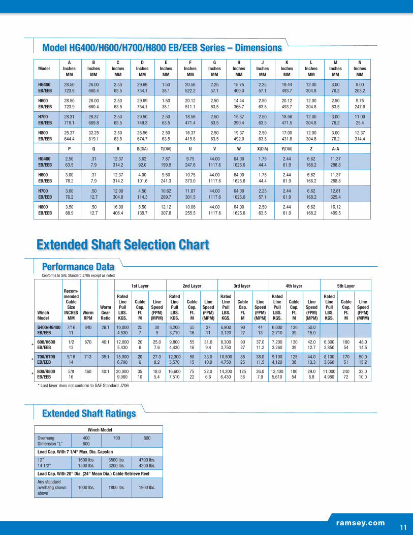
Engineered and developed specifically for utility applications, Ramsey Extended Shaft Worm Gear Winches are suitable for both front mount and behind-the-cab installation. Choose from low mount models that will accept a 7” capstan or 20” cable retrieve reel, and can be powered by hydraulic or mechanical drive. All models are available with single or double end extension shafts.
All models feature side-opening gear boxes, adjustable oil-cooled automatic safety brakes, free-spooling drum clutches (blocked clutches optional) and one-piece, heat-treated alloy steel worm gears supported by angular contact ball bearings which never need adjustment.
For more information, see Extended Gear Winch Brochure.
Extended Shaft Winches
MODEL G400/600/700/800 EB/EEB SERIES
MODEL HG400/H600/H700/H800 EB/EEB SERIES
AC
C B D
N
M
L
P
VW
STQ
R
U
L
X
Z
Y
M
N
DBC
C
A
FE EKJHG
P
LQ
R
ST U X
L
Y
Z
W
V
A-A
EKJHGFE
Model HG400/H600/H700/H800 EB/EEB Series Dimensions
ramsey.com10 11
1st Layer 2nd Layer 3rd layer 4th layer 5th Layer Recom- mended Rated Rated Rated Rated Rated Cable Line Cable Line Line Cable Line Line Cable Line Line Cable Line Line Cable Line Size Worm Pull Cap. Speed Pull Cap. Speed Pull Cap. Speed Pull Cap. Speed Pull Cap. Speed Winch INCHES Worm Gear LBS. Ft. (FPM) LBS. Ft. (FPM) LBS. Ft. (FPM) LBS. Ft. (FPM) LBS. Ft. (FPM) Model MM RPM Ratio KGS. M (MPM) KGS. M (MPM) KGS. M (MPM) KGS. M (MPM) KGS. M (MPM)
G400/HG400 7/16 840 29:1 10,000 25 30 8,200 55 37 6,900 90 44 6,000 130 50.0 EB/EEB 11 4,530 7 9 3,710 16 11 3,120 27 13 2,710 39 15.0
600/H600 1/2 870 40:1 12,000 20 25.0 9,800 55 31.0 8,300 90 37.0 7,200 130 42.0 6,300 180 48.0 EB/EEB 13 5,430 6 7.6 4,430 16 9.4 3,750 27 11.2 3,260 39 12.7 2,850 54 14.5
700/H700 9/16 713 35:1 15,000 20 27.0 12,300 50 33.0 10,500 85 38.0 9,100 125 44.0 8,100 170 50.0 EB/EEB 14 6,790 6 8.2 5,570 15 10.0 4,750 25 11.5 4,120 38 13.3 3,660 51 15.2
800/H800 5/8 460 40:1 20,000 35 18.0 16,600 75 22.0 14,200 125 26.0 12,400 180 29.0 11,000 240 33.0 EB/EEB 16 9,060 10 5.4 7,510 22 6.6 6,430 38 7.9 5,610 54 8.8 4,980 72 10.0
* Last layer does not conform to SAE Standard J706
*
*
*
Extended Shaft RatingsWinch Model
Overhang 400 700 800 Dimension “L” 600
Load Cap. With 7 1/4” Max. Dia. Capstan
12” 1600 lbs. 3500 lbs. 4700 lbs. 14 1/2” 1500 lbs. 3200 lbs. 4300 lbs.
Load Cap. With 20” Dia. (24” Mean Dia.) Cable Retrieve Reel
Any standard overhang shown 1000 lbs. 1800 lbs. 1900 lbs. above
Conforms to SAE Standard J706 except as noted
Performance Data
Model HG400/H600/H700/H800 EB/EEB Series – Dimensions A B C D E F G H J K L M N Model Inches Inches Inches Inches Inches Inches Inches Inches Inches Inches Inches Inches Inches MM MM MM MM MM MM MM MM MM MM MM MM MM
HG400 28.50 26.00 2.50 29.69 1.50 20.56 2.25 15.75 2.25 19.44 12.00 3.00 8.00 EB/EEB 723.9 660.4 63.5 754.1 38.1 522.2 57.1 400.0 57.1 493.7 304.8 76.2 203.2
H600 28.50 26.00 2.50 29.69 1.50 20.12 2.50 14.44 2.50 20.12 12.00 2.50 9.75 EB/EEB 723.9 660.4 63.5 754.1 38.1 511.1 63.5 366.7 63.5 493.7 304.8 63.5 247.6
H700 28.31 26.37 2.50 29.50 2.50 18.56 2.50 15.37 2.50 18.56 12.00 3.00 11.00 EB/EEB 719.1 669.8 63.5 749.3 63.5 471.4 63.5 390.4 63.5 471.5 304.8 76.2 25.4
H800 25.37 32.25 2.50 26.56 2.50 16.37 2.50 19.37 2.50 17.00 12.00 3.00 12.37 EB/EEB 644.4 819.1 63.5 674.7 63.5 415.8 63.5 492.0 63.5 431.8 304.8 76.2 314.4
P Q R S(DIA) T(DIA) U V W X(DIA) Y(DIA) Z A-A
HG400 2.50 .31 12.37 3.62 7.87 9.75 44.00 64.00 1.75 2.44 6.62 11.37 EB/EEB 63.5 7.9 314.2 92.0 199.9 247.6 1117.6 1625.6 44.4 61.9 168.2 288.8
H600 3.00 .31 12.37 4.00 9.50 10.75 44.00 64.00 1.75 2.44 6.62 11.37 EB/EEB 76.2 7.9 314.2 101.6 241.3 373.0 1117.6 1625.6 44.4 61.9 168.2 288.8
H700 3.00 .50 12.00 4.50 10.62 11.87 44.00 64.00 2.25 2.44 6.62 12.81 EB/EEB 76.2 12.7 304.8 114.3 269.7 301.5 1117.6 1625.6 57.1 61.9 168.2 325.4
H800 3.50 .50 16.00 5.50 12.12 10.06 44.00 64.00 2.50 2.44 6.62 16.12 EB/EEB 88.9 12.7 406.4 139.7 307.8 255.5 1117.6 1625.6 63.5 61.9 168.2 409.5
Extended Shaft Selection Chart

12 13
Thousands of Ramsey Worm Gear Speed Reducers have proven their value in a wide range of applications, from pipelining equipment to conveyor belts. For more information, see Speed Reducers and Transmissions Brochure.
Worm Gear Speed Reducers
Model S-200 – Dimensions
[31.7]1.25?
[130.8]5.15
[314.3]12.38
[157.2]6.19
[166.6]6.56
[214.3]8.44
[63.5]2.50
[31.7]1.25
[63.5]2.50?
[65.1]2.56
[196.9]7.75
[273.1]10.75
[68.6]2.70
[174.5]6.87
[191.1]7.53
(TYP. EACH END)
KEYWAY (TYP. EACH END).15 X .31 X 2.00 LG.
(2-PLACES EACH SIDE)
3/4-10UNC X 1.00 DEEP
KEYWAY.312 X .625
DIMENSIONS SHOWN ARE INCHES OVER MILLIMETERS
Model S-800 – Dimensions
DIMENSIONS SHOWN ARE INCHES OVER MILLIMETERS
[28.4]1.12
[31.7]1.25?
[44.4]1.75
[139.7]5.50
[197.6]7.78
[52.3]2.06
[63.5]2.50
[34.7]1.37
[115.8]4.56
[143.0]5.63
[119.1]4.69
[89.1]3.51
[19.0].75?
[92.0]3.62
[188.9]7.44
[94.4]3.72
(TYP. EACH END)
KEYWAY.315 X .157
& 1.00 DEEP (OUTPUT SHAFT SIDE)3/8-16UNC X .44 DEEP (COVER SIDE)
KEYWAY (TYP. EACH END).09 X .19 X 1.06 LG.

ramsey.com12 13
How to Select and Order Your Speed Reducer1. Torque – Check the performance data tables and choose the model or models having rated output torque equal or greater than
the torque required for the job.
2. Speed – Note the maximum input RPM. Do not exceed this RPM.
To order, specify model number, dimensions and specifications of output shaft (if not standard); state whether output shaft is to rotate in same direction or opposite direction of input shaft rotation; whether output shaft should be extended to right or left (when facing input) and whether automatic worm brake is desired as an extra.
Note: Specifications and Performance data are based on NO overhung load.
Worm Gear Speed Reducer Selection Chart
Rated Rated Output Input Torque Torque Model In./Lbs. In./Lbs. S7 4,800 400 1,200 38:1
S200 15,500 800 1,000 60:1 S246 15,500 1,000 1,000 46:1 SD200 15,500 1,050 1,000 30:1
S400 26,600 2,650 900 29:1
S600 36,000 2,600 900 40:1 S700 53,000 4,350 700 35:1 S800 78,700 5,650 500 40:1 S930 99,300 7,100 400 41:1
MaxInputRPM
GearReduction
*Data is based on no overhung load. Outboard end of shaft must be supported.

Model-1 Level Winder For H-200, H-300, HDG-350 winches and others with 11 5/16” between drum flanges Kit #256048
Spring applied cable tensioners (available as shown)
14 15
Model-2 Level Winder for HY-200, HY-300, HDGY-350, HD-P 8000Y, HD-P 10000Y winches or others with 6 5/16”– 6 1/2” drums Kit #256052
Model-3 Level Winder forHD-P 8000S and HD-P 10000S( 9 3/4” DRUM) KIT #256078
Model-5 Level Winder for RPH 12000(9 3/4” Drum) Kit #256082
4.57
116,1
5.87
149,1
3.35
85,1
ON TOP LAYEROF CABLE
LEVEL WINDER
4.57
116,1
5.87
149,1
3.35
85,1
ON TOP LAYEROF CABLE
LEVEL WINDER
Options For Ramsey Winches: Worm Gear and Planetary
Model-4 Level Winder For H-400 winches with 11 5/8” drum Kit #256076
1.38 ±.50
CLEAT
15 ∞ (ON BARE DRUM)
5.83
3.81
148,0
96,74.57
116,1
5.87
149,1
3.35
85,1
ON TOP LAYEROF CABLE
LEVEL WINDER
Model H-600 Spring TensionerKit #256096
14
CLEAT
2.00±.50
15∞ (ON BARE DRUM)
147,85.82
96,53.80
5.23132,8
279,411.00
3.1981,0
7.13181,1
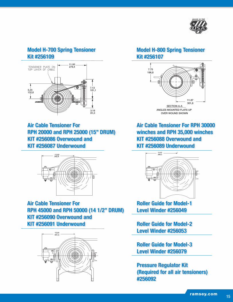
Model H-700 Spring Tensioner Kit #256109
ramsey.com14 15
ramsey.com15
Air Cable Tensioner ForRPH 20000 and RPH 25000 (15” DRUM)KIT #256086 Overwound and KIT #256087 Underwound
13.50342,9
Air Cable Tensioner ForRPH 45000 and RPH 50000 (14 1/2” DRUM)KIT #256090 Overwound and KIT #256091 Underwound
Air Cable Tensioner For RPH 30000 winches and RPH 35,000 winchesKIT #256088 Overwound andKIT #256089 Underwound
14.50368,3
15.81401,5
Options For Ramsey Winches: Worm Gear and Planetary
SECTION A-A
ANGLES MOUNTED FLATS DOWN ANGLES MOUNTED FLATS UP
SECTION A-A
OVER WOUND SHOWNUNDER WOUND SHOWN
11.87301,6
7.75196,8
11.87301,6
7.75196,8
Model H-800 Spring Tensioner Kit #256107
Roller Guide for Model-1 Level Winder #256049
Roller Guide for Model-2 Level Winder #256053
Roller Guide for Model-3 Level Winder #256079
Pressure Regulator Kit (Required for all air tensioners) #256092

P.O. Box 581510 • Tulsa, OK 74158-1510 U.S.A • Phone: (918) 438-2760 • Fax: (918) 438-6688
For more information visit:
ramsey.com
PN-915069 Printed in the U.S.A. PG 7.5M 107