hydraulic power units - opcdn.netopcdn.net/file/m_148/w_58/uploads/file/hpu.pdf · shafer has been...
TRANSCRIPT
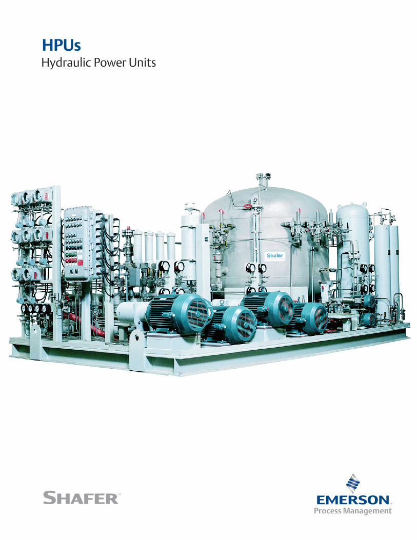
HPUsHydraulic Power Units
2
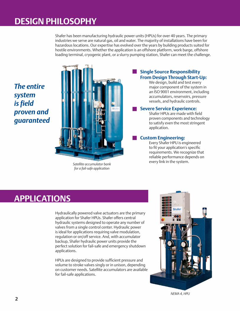
Hydraulically powered valve actuators are the primary application for Shafer HPUs. Shafer offers central hydraulic systems designed to operate any number of valves from a single control center. Hydraulic power is ideal for applications requiring valve modulation, regulation or on/off service. And, with accumulator backup, Shafer hydraulic power units provide the perfect solution for fail-safe and emergency shutdown applications.
HPUs are designed to provide sufficient pressure and volume to stroke valves singly or in unison, depending on customer needs. Satellite accumulators are available for fail-safe applications.
NEMA 4, HPU
The entire system is field proven and guaranteed
Shafer has been manufacturing hydraulic power units (HPUs) for over 40 years. The primary industries we serve are natural gas, oil and water. The majority of installations have been for hazardous locations. Our expertise has evolved over the years by building products suited for hostile environments. Whether the application is an offshore platform, work barge, offshore loading terminal, cryogenic plant, or a slurry pumping station, Shafer can meet the challenge.
Single Source Responsibility From Design Through Start-Up: We design, build and test every
major component of the system in an ISO 9001 environment, including accumulators, reservoirs, pressure vessels, and hydraulic controls.
Severe Service Experience: Shafer HPUs are made with field
proven components and technology to satisfy even the most stringent application.
Custom Engineering: Every Shafer HPU is engineered
to fit your application's specific requirements. We recognize that reliable performance depends on every link in the system.
Satellite accumulator bankfor a fail-safe application
DESIGN PHILOSOPHY
APPLICATIONS
3
Features
All pressure vessels and accumulators are constructed, inspected and certified (“U” Stamped) to ASME Section VIII
Only SAE O-ring type fittings are used on the nitrogen side of accumulators in order to prevent nitrogen leakage
Accumulator pistons contain a small oil-filled cavity designed to lubricate the nitrogen side of the piston seals preventing seal failure associated with infrequent operation
The oil reservoir is pressurized to assist pump suction. The HPU reservoir is closed to the atmosphere preventing ingress of moisture and contaminants which is critical when using biodegradable fluids
Capabilities
HPUs from 5 gallon capacity to 2000 gallon capacity
Operating pressures up to 3000 psi with standard components
Biodegradable hydraulic fluids or petroleum based fluids
Electrical classifications NEMA 4, 4X, 7, 9 or comparable CENELEC standards
Offshore trim with Ameron high performance coating systems where required
PLC or relay based control logic
Energy sources:
• Electric motors• Pneumatic driven hydraulic pumps• Solar power to electric motors• Gasoline or diesel fuel engines
• Any combination of energy sources
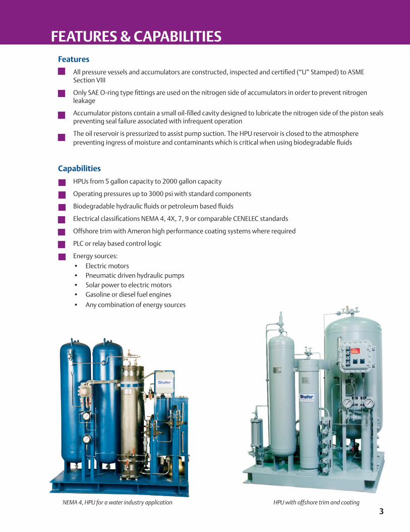
NEMA 4, HPU for a water industry application HPU with offshore trim and coating
FEATURES & CAPABILITIES
4
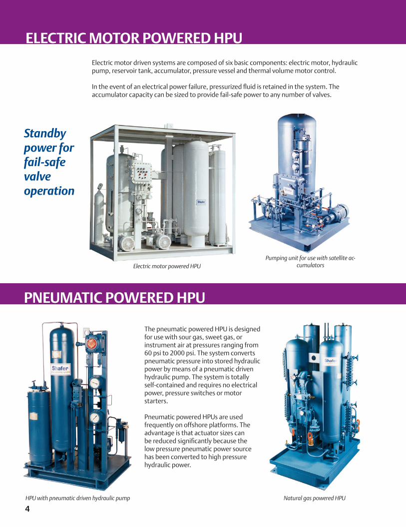
The pneumatic powered HPU is designed for use with sour gas, sweet gas, or instrument air at pressures ranging from 60 psi to 2000 psi. The system converts pneumatic pressure into stored hydraulic power by means of a pneumatic driven hydraulic pump. The system is totally self-contained and requires no electrical power, pressure switches or motor starters.
Pneumatic powered HPUs are used frequently on offshore platforms. The advantage is that actuator sizes can be reduced significantly because the low pressure pneumatic power source has been converted to high pressure hydraulic power.
HPU with pneumatic driven hydraulic pump Natural gas powered HPU
Electric motor driven systems are composed of six basic components: electric motor, hydraulic pump, reservoir tank, accumulator, pressure vessel and thermal volume motor control.
In the event of an electrical power failure, pressurized fluid is retained in the system. The accumulator capacity can be sized to provide fail-safe power to any number of valves.
Pumping unit for use with satellite ac-cumulatorsElectric motor powered HPU
Standby power for fail-safe valve operation
PNEUMATIC POWERED HPU
ELECTRIC MOTOR POWERED HPU
5
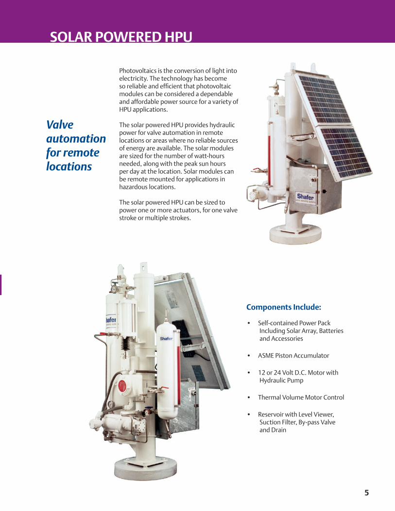
Components Include:
• Self-contained Power Pack Including Solar Array, Batteries and Accessories
• ASME Piston Accumulator
• 12 or 24 Volt D.C. Motor with Hydraulic Pump
• Thermal Volume Motor Control
• Reservoir with Level Viewer, Suction Filter, By-pass Valve and Drain
Photovoltaics is the conversion of light into electricity. The technology has become so reliable and efficient that photovoltaic modules can be considered a dependable and affordable power source for a variety of HPU applications.
The solar powered HPU provides hydraulic power for valve automation in remote locations or areas where no reliable sources of energy are available. The solar modules are sized for the number of watt-hours needed, along with the peak sun hours per day at the location. Solar modules can be remote mounted for applications in hazardous locations.
The solar powered HPU can be sized to power one or more actuators, for one valve stroke or multiple strokes.
Valve automation for remote locations
SOLAR POWERED HPU
The thermal volume motor control is an integral part of every Shafer hydraulic power system. Originally developed by Shafer, the thermal volume motor control provides several important performance advantages over systems utilizing pressure switches or pressure sensors for the motor start/stop function.
The thermal volume motor control insures that the accumulators fill completely or top out. This feature is critical in fail-safe applications where the stored hydraulic fluid is required to shut down valves in the event of electrical or power source failure.
The thermal volume motor control absorbs all volumetric changes in fluid over a wide temperature range and eliminates temperature induced cycling of the motor.
While the HPU is idle, relief valves will never open due to thermal expansion of hydraulic fluid because the volumetric changes are absorbed by the thermal volume control. The accumulator always remains fully charged.
Recharge time is reduced because there is no pressure dead band with which to contend. The motor/pump begins running before the accumulator even begins to discharge fluid to the actuators.
6
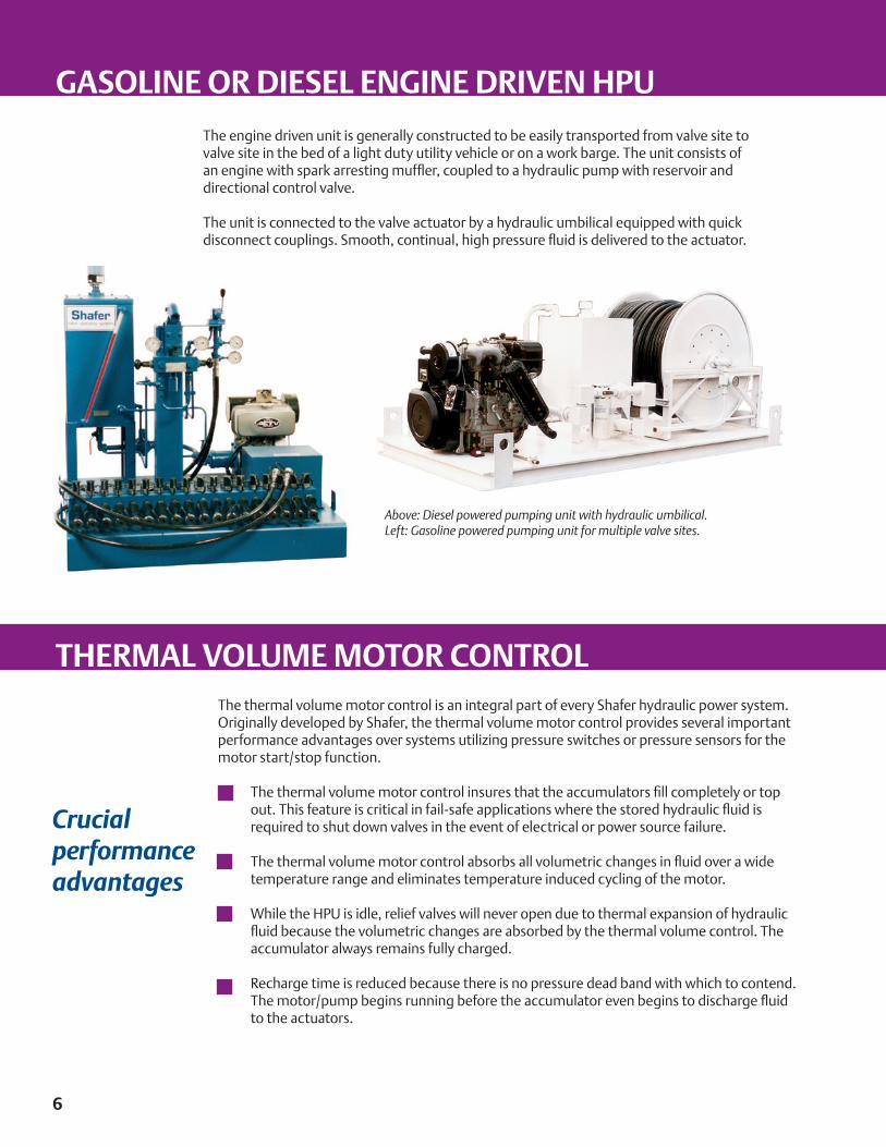
The engine driven unit is generally constructed to be easily transported from valve site to valve site in the bed of a light duty utility vehicle or on a work barge. The unit consists of an engine with spark arresting muffler, coupled to a hydraulic pump with reservoir and directional control valve.
The unit is connected to the valve actuator by a hydraulic umbilical equipped with quick disconnect couplings. Smooth, continual, high pressure fluid is delivered to the actuator.
Above: Diesel powered pumping unit with hydraulic umbilical.Left: Gasoline powered pumping unit for multiple valve sites.
Crucial performance advantages
GASOLINE OR DIESEL ENGINE DRIVEN HPU
THERMAL VOLUME MOTOR CONTROL
7
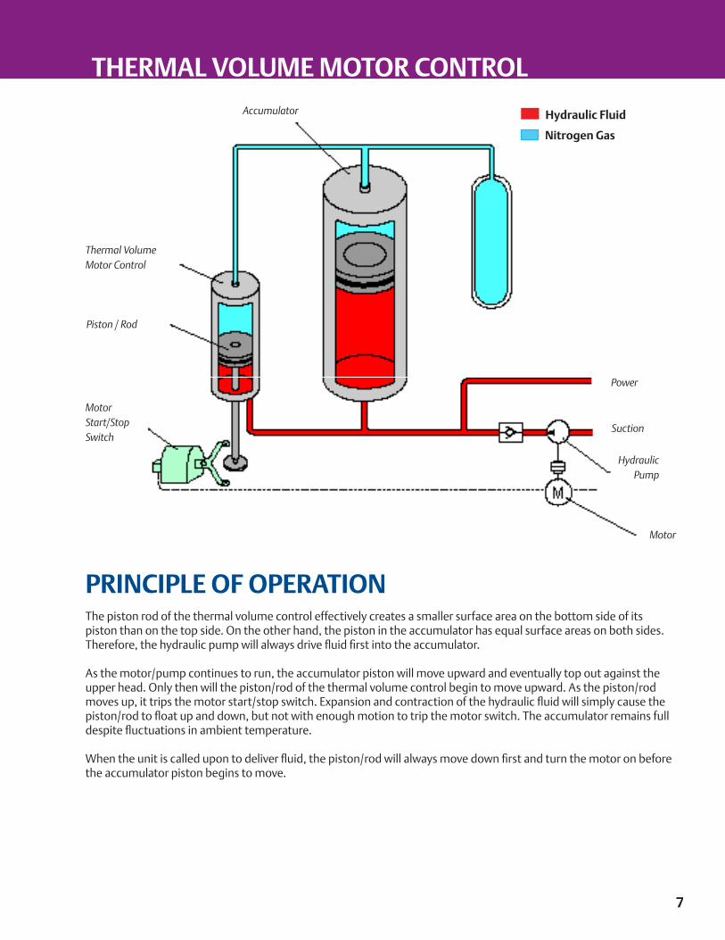
PRINCIPLE OF OPERATIONThe piston rod of the thermal volume control effectively creates a smaller surface area on the bottom side of its piston than on the top side. On the other hand, the piston in the accumulator has equal surface areas on both sides. Therefore, the hydraulic pump will always drive fluid first into the accumulator.
As the motor/pump continues to run, the accumulator piston will move upward and eventually top out against the upper head. Only then will the piston/rod of the thermal volume control begin to move upward. As the piston/rod moves up, it trips the motor start/stop switch. Expansion and contraction of the hydraulic fluid will simply cause the piston/rod to float up and down, but not with enough motion to trip the motor switch. The accumulator remains full despite fluctuations in ambient temperature.
When the unit is called upon to deliver fluid, the piston/rod will always move down first and turn the motor on before the accumulator piston begins to move.
Thermal VolumeMotor Control
Piston / Rod
MotorStart/Stop Switch
Power
Suction
Motor
HydraulicPump
Accumulator Hydraulic Fluid
Nitrogen Gas
THERMAL VOLUME MOTOR CONTROL