hydraulic valves & accessories - hydraulic supply company home
TRANSCRIPT

This page is part of a complete catalog which contains technical and safety data that must be reviewed when selecting a product
Hydraulic Valves & AccessoriesCategory Page
Hyd
raul
ic P
ower
& C
ontr
olP
neum
atic
Pow
er &
Con
trol
Flu
id C
onve
ying
Mis
cella
neou
s P
rodu
cts
Inde
xes
& T
echn
ical
Info
rmat
ion
238 1999-2016 Hydraulic Supply Co. • 1-800-507-9651 • www.hydraulic-supply.com
Ball Valves . . . . . . . . . . . . . . . . . . . . . . . . . . . . . . . . . . . . . . . . . . . . . . . . . . . . . . . . . . . . . . . . . . . . . . . . . . . . . 241Check Valves, Pilot-Operated Check Valves. . . . . . . . . . . . . . . . . . . . . . . . . . . . . . . . . . . . . . . . . . . . . . . . . . 247Counterbalance Valves (Overcenter Valves). . . . . . . . . . . . . . . . . . . . . . . . . . . . . . . . . . . . . . . . . . . . . . . . . . 266Cushion Valves . . . . . . . . . . . . . . . . . . . . . . . . . . . . . . . . . . . . . . . . . . . . . . . . . . . . . . . . . . . . . . . . . . . . . . . . . 276Directional Control Valves . . . . . . . . . . . . . . . . . . . . . . . . . . . . . . . . . . . . . . . . . . . . . . . . . . . . . . . . . . . . . . . . 280
Manually-Operated . . . . . . . . . . . . . . . . . . . . . . . . . . . . . . . . . . . . . . . . . . . . . . . . . . . . . . . . . . . . . . . . . . . . . . 280Eaton MPV1-10 Series 2-Way 2-Position Cartridge Valves (To 12 GPM & 3000 PSI) . . . . . . . . . . . . . . . . . 280Eaton DG17V-3 Series Subplate Mounted (NFPA Size D03, ISO 4401 Size 03) . . . . . . . . . . . . . . . . . . . . . 282Eaton DG17V-8 Series Subplate Mounted (NFPA Size D08, ISO 4401 Size 08) . . . . . . . . . . . . . . . . . . . . . 283
Monoblock . . . . . . . . . . . . . . . . . . . . . . . . . . . . . . . . . . . . . . . . . . . . . . . . . . . . . . . . . . . . . . . . . . . . . . . . . . . . 284Eaton 30900 Series 1-3 Spool (To 5 GPM & 3000 PSI) . . . . . . . . . . . . . . . . . . . . . . . . . . . . . . . . . . . . . . . . 284Salami VDM6 Series (12 GPM Nominal To 5100 PSI) . . . . . . . . . . . . . . . . . . . . . . . . . . . . . . . . . . . . . . . . . 285Walvoil SD4 Series (To 12 GPM Nominal, To 3600 PSI) . . . . . . . . . . . . . . . . . . . . . . . . . . . . . . . . . . . . . . . 288Walvoil SD5 Series (To 12 GPM Nominal, To 4600 PSI) . . . . . . . . . . . . . . . . . . . . . . . . . . . . . . . . . . . . . . . 289Walvoil SD11 Series (To 18 GPM Nominal, To 4600 PSI) . . . . . . . . . . . . . . . . . . . . . . . . . . . . . . . . . . . . . . 290Brand Hydraulics AO755 Series 1 Spool (To 18 GPM & 3000 PSI) . . . . . . . . . . . . . . . . . . . . . . . . . . . . . . . 292Brand Hydraulics LS755 Series 1-Spool (To 18 GPM & 3000 PSI) . . . . . . . . . . . . . . . . . . . . . . . . . . . . . . . 293Brand Hydraulics SDCF Series 1-Spool (To 18 GPM & 3000 PSI). . . . . . . . . . . . . . . . . . . . . . . . . . . . . . . . 294Salami VDM8 Series (20 GPM Nominal To 5100 PSI) . . . . . . . . . . . . . . . . . . . . . . . . . . . . . . . . . . . . . . . . . 295
Proportional . . . . . . . . . . . . . . . . . . . . . . . . . . . . . . . . . . . . . . . . . . . . . . . . . . . . . . . . . . . . . . . . . . . . . . . . . . . 298Eaton KDG4V-3 & -3S Series, without Feedback (NFPA Size D03, ISO 4401 Size 03). . . . . . . . . . . . . . . . 298Eaton KFDG4V-3 Series, with Feedback (NFPA Size D03, ISO 4401 Size 03) . . . . . . . . . . . . . . . . . . . . . . 300
Sectional . . . . . . . . . . . . . . . . . . . . . . . . . . . . . . . . . . . . . . . . . . . . . . . . . . . . . . . . . . . . . . . . . . . . . . . . . . . . . . 301Salami VD6A Series (12 GPM Nominal To 5100 PSI) . . . . . . . . . . . . . . . . . . . . . . . . . . . . . . . . . . . . . . . . . 301Walvoil SD6 Series (12 GPM Nominal, To 4600 PSI) . . . . . . . . . . . . . . . . . . . . . . . . . . . . . . . . . . . . . . . . . . 305Salami VD8A Series (20 GPM Nominal To 5100 PSI) . . . . . . . . . . . . . . . . . . . . . . . . . . . . . . . . . . . . . . . . . 308Husco Model 5000 (20 GPM Nominal Flow Rating, To 3000 PSI) . . . . . . . . . . . . . . . . . . . . . . . . . . . . . . . . 313Walvoil SD8 Series (21 GPM Nominal Flow Rating, To 4600 PSI) . . . . . . . . . . . . . . . . . . . . . . . . . . . . . . . . 314Walvoil SDS150 Series (24 GPM Nominal Flow Rating, To 4600 PSI). . . . . . . . . . . . . . . . . . . . . . . . . . . . . 318Salami VDP08 Series (25 GPM Nominal To 4560 PSI) . . . . . . . . . . . . . . . . . . . . . . . . . . . . . . . . . . . . . . . . 322Salami VD10A Series (32 GPM Nominal To 4000 PSI) . . . . . . . . . . . . . . . . . . . . . . . . . . . . . . . . . . . . . . . . 326Walvoil SD16 Series (37 GPM Nominal Flow Rating, To 4600 PSI) . . . . . . . . . . . . . . . . . . . . . . . . . . . . . . . 330Husco Model 6000 (40 GPM Nominal Flow Rating, To 3400 PSI) . . . . . . . . . . . . . . . . . . . . . . . . . . . . . . . . 333Salami VD12A Series (48 GPM Nominal To 4000 PSI) . . . . . . . . . . . . . . . . . . . . . . . . . . . . . . . . . . . . . . . . 334Walvoil SD25 Series (63 GPM Nominal Flow Rating, To 4600 PSI) . . . . . . . . . . . . . . . . . . . . . . . . . . . . . . . 338
Solenoid-Operated . . . . . . . . . . . . . . . . . . . . . . . . . . . . . . . . . . . . . . . . . . . . . . . . . . . . . . . . . . . . . . . . . . . . . . 341Screw-In Cartridge Valves (2-way, 3-way, 4-way). . . . . . . . . . . . . . . . . . . . . . . . . . . . . . . . . . . . . . . . . . . . . 341Eaton DG4V-3 & -3S Series Subplate Mounted (NFPA Size D03, ISO 4401 Size 03) . . . . . . . . . . . . . . . . . 372Eaton DG4V-3 Series Soft Shift Subplate Mounted (NFPA Size D03, ISO 4401 Size 03) . . . . . . . . . . . . . . 376Eaton DG4S4-01 60 Series Subplate Mounted (NFPA Size D05, ISO 4401 Size 05) . . . . . . . . . . . . . . . . . 378Eaton DG4V4-01 10 Series High Pressure Subplate Mounted (NFPA Size D05, ISO 4401 Size 05) . . . . . 381Eaton DG4V5 20 Series High Pressure Subplate Mounted (NFPA Size D05, ISO 4401 Size 05) . . . . . . . . 383Eaton DG4S4-01 60 Series Soft Shift Subplate Mounted (NFPA Size D05, ISO 4401 Size 05) . . . . . . . . . 384Eaton DG4S4-0150 Series (Air Gap) Subplate Mounted (NFPA Size D05, ISO 4401 Size 05) . . . . . . . . . . 385Eaton DG5V-8 Series Subplate Mounted (NFPA Size D08, ISO 4401 Size 08) . . . . . . . . . . . . . . . . . . . . . . 386Eaton DG5V-10 Series Subplate Mounted (NFPA Size D10, ISO 4401 Size 10) . . . . . . . . . . . . . . . . . . . . . 387
Flow Control Valves. . . . . . . . . . . . . . . . . . . . . . . . . . . . . . . . . . . . . . . . . . . . . . . . . . . . . . . . . . . . . . . . . . . . . . 388Flow Divider Valves . . . . . . . . . . . . . . . . . . . . . . . . . . . . . . . . . . . . . . . . . . . . . . . . . . . . . . . . . . . . . . . . . . . . . . 402Gate Valves. . . . . . . . . . . . . . . . . . . . . . . . . . . . . . . . . . . . . . . . . . . . . . . . . . . . . . . . . . . . . . . . . . . . . . . . . . . . . 405Logic Element Valves . . . . . . . . . . . . . . . . . . . . . . . . . . . . . . . . . . . . . . . . . . . . . . . . . . . . . . . . . . . . . . . . . . . . 406Needle Valves. . . . . . . . . . . . . . . . . . . . . . . . . . . . . . . . . . . . . . . . . . . . . . . . . . . . . . . . . . . . . . . . . . . . . . . . . . . 407Plug Valves. . . . . . . . . . . . . . . . . . . . . . . . . . . . . . . . . . . . . . . . . . . . . . . . . . . . . . . . . . . . . . . . . . . . . . . . . . . . . 411

Hydraulic Valves & Accessories
This page is part of a complete catalog which contains technical and safety data that must be reviewed when selecting a product
Category Page Hydraulic P
ower &
Control
Pneum
atic Pow
er & C
ontrolF
luid Conveying
Miscellaneous P
roductsIndexes &
Technical Information
239 1999-2016 Hydraulic Supply Co. • 1-800-507-9651 • www.hydraulic-supply.com
Pressure Reducing Valves . . . . . . . . . . . . . . . . . . . . . . . . . . . . . . . . . . . . . . . . . . . . . . . . . . . . . . . . . . . . . . . . 413Direct-Acting (To 4 GPM & 2400 PSI) . . . . . . . . . . . . . . . . . . . . . . . . . . . . . . . . . . . . . . . . . . . . . . . . . . . . . 413Pilot-Operated (To 10 GPM & 3500 PSI) . . . . . . . . . . . . . . . . . . . . . . . . . . . . . . . . . . . . . . . . . . . . . . . . . . . 414
Relief Valves. . . . . . . . . . . . . . . . . . . . . . . . . . . . . . . . . . . . . . . . . . . . . . . . . . . . . . . . . . . . . . . . . . . . . . . . . . . . 416Direct-Acting Ball Type Fast acting • Intermittent duty • Low cost • Possibly noisy • Higher overpressure . 416Direct-Acting Poppet Type Fast acting • Continuous duty • Low cost . . . . . . . . . . . . . . . . . . . . . . . . . . . . . 417Direct-Acting Differential Poppet Type Fast acting • Intermittent duty • Contaminant tolerant . . . . . . . . . . . 418Pilot-Operated Poppet Type Anti-Cavitation Make-Up Feature . . . . . . . . . . . . . . . . . . . . . . . . . . . . . . . . . . 420Pilot-Operated Spool Type Quiet, smooth & consistent • Continuous duty • Low overpressure . . . . . . . . . 421Guided Piston Type Quiet • Stable • Flow Modulating . . . . . . . . . . . . . . . . . . . . . . . . . . . . . . . . . . . . . . . . . 425
Sandwich Valves (Aluminum Housings, Blanking-Linking-Spacer Plates) . . . . . . . . . . . . . . . . . . . . . . . . . 426Selector Valves . . . . . . . . . . . . . . . . . . . . . . . . . . . . . . . . . . . . . . . . . . . . . . . . . . . . . . . . . . . . . . . . . . . . . . . . . 427Slip-In Cartridge Valves. . . . . . . . . . . . . . . . . . . . . . . . . . . . . . . . . . . . . . . . . . . . . . . . . . . . . . . . . . . . . . . . . . . 431Stack Valves . . . . . . . . . . . . . . . . . . . . . . . . . . . . . . . . . . . . . . . . . . . . . . . . . . . . . . . . . . . . . . . . . . . . . . . . . . . . 432
NFPA Size D03 - ISO 4401 Size 03 . . . . . . . . . . . . . . . . . . . . . . . . . . . . . . . . . . . . . . . . . . . . . . . . . . . . . . . . . 432NFPA Size D05 - ISO 4401 Size 05 . . . . . . . . . . . . . . . . . . . . . . . . . . . . . . . . . . . . . . . . . . . . . . . . . . . . . . . . . 435
System Accessory Valves. . . . . . . . . . . . . . . . . . . . . . . . . . . . . . . . . . . . . . . . . . . . . . . . . . . . . . . . . . . . . . . . . 437Shuttle Valves. . . . . . . . . . . . . . . . . . . . . . . . . . . . . . . . . . . . . . . . . . . . . . . . . . . . . . . . . . . . . . . . . . . . . . . . . . 437
Truck Valves. . . . . . . . . . . . . . . . . . . . . . . . . . . . . . . . . . . . . . . . . . . . . . . . . . . . . . . . . . . . . . . . . . . . . . . . . . . . 439Valve Accessories . . . . . . . . . . . . . . . . . . . . . . . . . . . . . . . . . . . . . . . . . . . . . . . . . . . . . . . . . . . . . . . . . . . . . . . 440
Bolt & Bolt Extender Kits. . . . . . . . . . . . . . . . . . . . . . . . . . . . . . . . . . . . . . . . . . . . . . . . . . . . . . . . . . . . . . . . . . 440Cartridge Valve Housings . . . . . . . . . . . . . . . . . . . . . . . . . . . . . . . . . . . . . . . . . . . . . . . . . . . . . . . . . . . . . . . . . 441Cartridge Valve Coils . . . . . . . . . . . . . . . . . . . . . . . . . . . . . . . . . . . . . . . . . . . . . . . . . . . . . . . . . . . . . . . . . . . . 445Solenoid Connectors . . . . . . . . . . . . . . . . . . . . . . . . . . . . . . . . . . . . . . . . . . . . . . . . . . . . . . . . . . . . . . . . . . . . 446
Electronic Control Components . . . . . . . . . . . . . . . . . . . . . . . . . . . . . . . . . . . . . . . . . . . . . . . . . . . . . . . . . . . . 449Subplates, Manifolds, Cover Plates, Valve Adaptors . . . . . . . . . . . . . . . . . . . . . . . . . . . . . . . . . . . . . . . . . . . . 450
Valve Technical Information, Performance, Dimensions. . . . . . . . . . . . . . . . . . . . . . . . . . . . . . . . . . . . . . . . 662Ball Valves . . . . . . . . . . . . . . . . . . . . . . . . . . . . . . . . . . . . . . . . . . . . . . . . . . . . . . . . . . . . . . . . . . . . . . . . . . . . 662
Stauff 2BVM Ball Valve Pressure-Temperature Graphs . . . . . . . . . . . . . . . . . . . . . . . . . . . . . . . . . . . . . . . . 662Stauff 2BVL Ball Valve Pressure-Temperature Graphs . . . . . . . . . . . . . . . . . . . . . . . . . . . . . . . . . . . . . . . . 663Apollo® Pressure-Temperature Graphs . . . . . . . . . . . . . . . . . . . . . . . . . . . . . . . . . . . . . . . . . . . . . . . . . . . . 664
Directional Control Valves, Hydraulic . . . . . . . . . . . . . . . . . . . . . . . . . . . . . . . . . . . . . . . . . . . . . . . . . . . . . . . . 667Brand AO755 Series . . . . . . . . . . . . . . . . . . . . . . . . . . . . . . . . . . . . . . . . . . . . . . . . . . . . . . . . . . . . . . . . . . . 667Brand LS755 Series . . . . . . . . . . . . . . . . . . . . . . . . . . . . . . . . . . . . . . . . . . . . . . . . . . . . . . . . . . . . . . . . . . . 667Brand SDCF Series . . . . . . . . . . . . . . . . . . . . . . . . . . . . . . . . . . . . . . . . . . . . . . . . . . . . . . . . . . . . . . . . . . . . 668Eaton 30900 Series . . . . . . . . . . . . . . . . . . . . . . . . . . . . . . . . . . . . . . . . . . . . . . . . . . . . . . . . . . . . . . . . . . . . 669Husco Model 5000. . . . . . . . . . . . . . . . . . . . . . . . . . . . . . . . . . . . . . . . . . . . . . . . . . . . . . . . . . . . . . . . . . . . . 670Husco Model 6000. . . . . . . . . . . . . . . . . . . . . . . . . . . . . . . . . . . . . . . . . . . . . . . . . . . . . . . . . . . . . . . . . . . . . 671Vickers® DG4V-3 & DG4V-3S Series . . . . . . . . . . . . . . . . . . . . . . . . . . . . . . . . . . . . . . . . . . . . . . . . . . . . . . 672Vickers® DG4V-3 & DG4V-3S Series Soft Shift . . . . . . . . . . . . . . . . . . . . . . . . . . . . . . . . . . . . . . . . . . . . . . 675Vickers® DG4S-01 Series, -60 Design (Wet Armature) . . . . . . . . . . . . . . . . . . . . . . . . . . . . . . . . . . . . . . . . 676Vickers® DG4S-01 Series Soft Shift, -60 Design, Wet Armature . . . . . . . . . . . . . . . . . . . . . . . . . . . . . . . . . 677Vickers® DG4S-01 Series, -50 Design (Air Gap) . . . . . . . . . . . . . . . . . . . . . . . . . . . . . . . . . . . . . . . . . . . . . 678Vickers® DG4V4-01 Series, -10 Design . . . . . . . . . . . . . . . . . . . . . . . . . . . . . . . . . . . . . . . . . . . . . . . . . . . . 679Vickers® DG4V-5 Series, -20 Design . . . . . . . . . . . . . . . . . . . . . . . . . . . . . . . . . . . . . . . . . . . . . . . . . . . . . . 680Vickers® DG5V-8 Series . . . . . . . . . . . . . . . . . . . . . . . . . . . . . . . . . . . . . . . . . . . . . . . . . . . . . . . . . . . . . . . . 681Vickers® DG5V-10 Series . . . . . . . . . . . . . . . . . . . . . . . . . . . . . . . . . . . . . . . . . . . . . . . . . . . . . . . . . . . . . . . 682Walvoil SD4 Series . . . . . . . . . . . . . . . . . . . . . . . . . . . . . . . . . . . . . . . . . . . . . . . . . . . . . . . . . . . . . . . . . . . . 683Walvoil SD5 Series . . . . . . . . . . . . . . . . . . . . . . . . . . . . . . . . . . . . . . . . . . . . . . . . . . . . . . . . . . . . . . . . . . . . 684Walvoil SD6 Series . . . . . . . . . . . . . . . . . . . . . . . . . . . . . . . . . . . . . . . . . . . . . . . . . . . . . . . . . . . . . . . . . . . . 685Walvoil SD8 Series . . . . . . . . . . . . . . . . . . . . . . . . . . . . . . . . . . . . . . . . . . . . . . . . . . . . . . . . . . . . . . . . . . . . 686Walvoil SD11 Series . . . . . . . . . . . . . . . . . . . . . . . . . . . . . . . . . . . . . . . . . . . . . . . . . . . . . . . . . . . . . . . . . . . 687Walvoil SD16 Series . . . . . . . . . . . . . . . . . . . . . . . . . . . . . . . . . . . . . . . . . . . . . . . . . . . . . . . . . . . . . . . . . . . 688

This page is part of a complete catalog which contains technical and safety data that must be reviewed when selecting a product
Hydraulic Valves & AccessoriesCategory Page
Hyd
raul
ic P
ower
& C
ontr
olP
neum
atic
Pow
er &
Con
trol
Flu
id C
onve
ying
Mis
cella
neou
s P
rodu
cts
Inde
xes
& T
echn
ical
Info
rmat
ion
240 1999-2016 Hydraulic Supply Co. • 1-800-507-9651 • www.hydraulic-supply.com
Walvoil SD25 Series . . . . . . . . . . . . . . . . . . . . . . . . . . . . . . . . . . . . . . . . . . . . . . . . . . . . . . . . . . . . . . . . . . . 689Walvoil SDS150 Series . . . . . . . . . . . . . . . . . . . . . . . . . . . . . . . . . . . . . . . . . . . . . . . . . . . . . . . . . . . . . . . . . 690Salami VDM6 Series . . . . . . . . . . . . . . . . . . . . . . . . . . . . . . . . . . . . . . . . . . . . . . . . . . . . . . . . . . . . . . . . . . . 691Salami SDM8 Series . . . . . . . . . . . . . . . . . . . . . . . . . . . . . . . . . . . . . . . . . . . . . . . . . . . . . . . . . . . . . . . . . . . 693Salami VD6A Series . . . . . . . . . . . . . . . . . . . . . . . . . . . . . . . . . . . . . . . . . . . . . . . . . . . . . . . . . . . . . . . . . . . 695Salami VD8A Series . . . . . . . . . . . . . . . . . . . . . . . . . . . . . . . . . . . . . . . . . . . . . . . . . . . . . . . . . . . . . . . . . . . 696Salami VD10A Series . . . . . . . . . . . . . . . . . . . . . . . . . . . . . . . . . . . . . . . . . . . . . . . . . . . . . . . . . . . . . . . . . . 697Salami VD12A Series . . . . . . . . . . . . . . . . . . . . . . . . . . . . . . . . . . . . . . . . . . . . . . . . . . . . . . . . . . . . . . . . . . 698Salami VDP08 Series . . . . . . . . . . . . . . . . . . . . . . . . . . . . . . . . . . . . . . . . . . . . . . . . . . . . . . . . . . . . . . . . . . 699
Relief Valves. . . . . . . . . . . . . . . . . . . . . . . . . . . . . . . . . . . . . . . . . . . . . . . . . . . . . . . . . . . . . . . . . . . . . . . . . . . 700Fulflo V Series Guided Piston Type. . . . . . . . . . . . . . . . . . . . . . . . . . . . . . . . . . . . . . . . . . . . . . . . . . . . . . . . 700
Stack Valves . . . . . . . . . . . . . . . . . . . . . . . . . . . . . . . . . . . . . . . . . . . . . . . . . . . . . . . . . . . . . . . . . . . . . . . . . . . 701Vickers® NFPA-D03 SystemStak Valves . . . . . . . . . . . . . . . . . . . . . . . . . . . . . . . . . . . . . . . . . . . . . . . . . . . 701Vickers® NFPA-D05 SystemStak Valves . . . . . . . . . . . . . . . . . . . . . . . . . . . . . . . . . . . . . . . . . . . . . . . . . . . 706

This page is part of a complete catalog which contains technical and safety data that must be reviewed when selecting a product
Hydraulic Valves & Accessories
Hydraulic P
ower &
Control
Pneum
atic Pow
er & C
ontrolF
luid Conveying
Miscellaneous P
roductsIndexes &
Technical Information
241 1999-2016 Hydraulic Supply Co. • 1-800-507-9651 • www.hydraulic-supply.com
Bronze Apollo® 70-100 Series
Features: Chromium plated ball. RPTFE seats and stuffing box ring. Blow-out proof stem design. Adjustable packing gland.
Standard Materials: Zinc plated steel lever (with vinyl cover) and lever nut. RPTFE seats, stem packing and stem bearing. B16 chrome plated ball. B16 retainer (1/4 through 1 inch). B584-C84400 retainer (1-1/4 through 3 inch). B16 gland nut and stem. PTFE body seal (1-1/4 through 3 inch). B584-C84400 body.
Pressure Ratings: 600 psig WOG, Cold Non-Shock. 150 psig Saturated Steam. Vacuum service to 29 in./Hg. Note: Valves have a reduced pressure rating at elevated temperatures. See "600# Bronze P-T Rating (Graph 4)
on page 664Note: Numerous options are available on special order. Contact us for assistance. Seal Kits: page 246
Bronze • Apollo® 70-100 Series
Catalog Part No. Apollo Model Ports
Ball Orifice
Dia.CV
Rating Special Features Seal Kit Wt.Price Each
•C1EN78 70-101-01 1/4 NPT 0.37 8.4 70-002-01 0.58
C1EN82 70-103-01 1/2 NPT 0.50 15 70-003-01 0.63
•C1EN84 70-104-01 3/4 NPT 0.68 30 70-004-01 1.39
•C1EN86 70-105-01 1 NPT 0.87 43 70-005-01 1.72
C1EN77 70-100-01 3 NPT 2.50 370 70-009-01 17.25
Ball Valves

This page is part of a complete catalog which contains technical and safety data that must be reviewed when selecting a product
Hydraulic Valves & Accessories
Hyd
raul
ic P
ower
& C
ontr
olP
neum
atic
Pow
er &
Con
trol
Flu
id C
onve
ying
Mis
cella
neou
s P
rodu
cts
Inde
xes
& T
echn
ical
Info
rmat
ion
242 1999-2016 Hydraulic Supply Co. • 1-800-507-9651 • www.hydraulic-supply.com
Brass Stauff 2BVL Series
Features: Brass Hot Stamping with Chrome Plated Brass Ball. Blow Out Proof Stem. Teflon Seats, Seals & Thrust Washer. Metal Handle.
Maximum Operating Pressure: Up to 600 PSI Temperature Range: Up to 320°F Up to 320°F at reduced pressure. See chart on page page 663
Brass • Stauff 2BVL SeriesCatalog Part No. Stauff Model Ports
Maximum Working Pressure (psi) Special Features Wt.
Price Each
•C1KU42 2BVL2004F-OSSS 1/4 NPT 600 Stainless steel off-set handle 0.30
•C1KU43 2BVL2006F-OSSS 3/8 NPT 600 Stainless steel off-set handle 0.30
•C1KU44 2BVL2008F-OSSS 1/2 NPT 435 Stainless steel off-set handle 0.40
•C1KU45 2BVL2012F-OSSS 3/4 NPT 435 Stainless steel off-set handle 0.71
•C1KU46 2BVL2016F-OSSS 1 NPT 435 Stainless steel off-set handle 1.00
•C1KU47 2BVL2020F-OSSS 1-1/4 NPT 435 Stainless steel off-set handle 1.70
C1KJ71 2BVL2024F 1-1/2 NPT 362 Carbon Steel, zinc plated handle 2.20
•C1KU48 2BVL2024F-OSSS 1-1/2 NPT 362 Stainless steel off-set handle 2.32
C1MJ31 2BVL2032F/2 2 NPT 362 Carbon Steel, zinc plated handle 4.50
•C1KU49 2BVL2032F-OSSS 2 NPT 362 Stainless steel off-set handle 4.20
C1MJ32 2BVL2R40FL 2-1/2 NPT 362 Carbon Steel, zinc plated handle 12.90
Stauff 2BVL Series Port Adaptors
Features: Leak Free O-Ring Sealing to 4" with a Variety of Connection Options: • Socket Weld • Hose Barb (Straight 45? & 90?) • Split Flange. Lock Nut Design Simplifies the Positioning of Valves and Eliminates Weld Damage to Valve.
Material: Carbon Steel Construction Seals: Buna N Seals
Stauff 2BVL Series • Port AdaptorsCatalog Part No. Stauff Model
Valve Size
Valve Thread Size A (in) B (in) C (in) Description Wt.
Price Each
C1LB93 HA90-40 2-1/2 2-1/2 -11 BSPP 5.25 8.06 2.50 SAE Swivel to Hose Barb 90° Adapter 6.44
C1LD11 SAS-40 2-1/2 2-1/2 -11 BSPP 3.18 2.50 3.31 SAE to Split Flange (Code 61) Adapter 2.43
Ball Valves

This page is part of a complete catalog which contains technical and safety data that must be reviewed when selecting a product
Hydraulic Valves & Accessories
Hydraulic P
ower &
Control
Pneum
atic Pow
er & C
ontrolF
luid Conveying
Miscellaneous P
roductsIndexes &
Technical Information
243 1999-2016 Hydraulic Supply Co. • 1-800-507-9651 • www.hydraulic-supply.com
Steel - Barstock Body Apollo® 73-100 Series
Features: Barstock design. RPTFE seats and stuffing box ring. Fire safe design when ordered with graphite packing. Adjustable packing gland. Blow-out proof stem design. Nitride corrosion protection.
Standard Materials: Zinc plated steel lever (with vinyl cover) and lever nut. RPTFE seats, stem packing and stem bearing. A 108-CS chrome plated ball. A 108-CS retainer. A 108-CS gland nut and stem. PTFE body seal (1-1/4 through 2 inch). A 108-CS body.
Pressure Ratings: 1/4 to 1 inch: 2000 psig WOG, Cold Non-Shock. 1-1/4 to 2 inch: 1500 psig WOG, Cold Non-Shock. 150 psig Saturated Steam. Vacuum service to 29 in./Hg.
Note: Valves have a reduced pressure rating at elevated temperatures. For 1/4 inch to 1 inch sizes, see "2000# CS P-T Rating (Graph 13) on page 665. For 1-1/4 inch to 2 inch sizes, see "1500# CS P-T Rating (Graph 11) on page 665
Note: Numerous options are available on special order. Contact us for assistance. Seal Kits: page 246
Steel - Barstock Body • Apollo® 73-100 Series
Catalog Part No. Apollo Model Ports
Ball Orifice
Dia.CV
Rating Special Features Seal Kit Wt.Price Each
•C1EP14 73-104-01 3/4 NPT 0.68 30 70-004-01 1.58
Ball Valves

This page is part of a complete catalog which contains technical and safety data that must be reviewed when selecting a product
Hydraulic Valves & Accessories
Hyd
raul
ic P
ower
& C
ontr
olP
neum
atic
Pow
er &
Con
trol
Flu
id C
onve
ying
Mis
cella
neou
s P
rodu
cts
Inde
xes
& T
echn
ical
Info
rmat
ion
244 1999-2016 Hydraulic Supply Co. • 1-800-507-9651 • www.hydraulic-supply.com
Steel - Barstock Body Stauff BBVM Series
Features: Fully ported. Carbon steel body. Chrome plated brass ball. 50,000 cycle seal life. Delrin seats. Viton® O-Rings.
Maximum Operating Pressure: Sizes 1/4 - 1/2: 7250 PSI. Sizes 3/4: 6000 PSI; Sizes 1 - 1-1/4: 4500 PSI; Size 1-1/2: 3600 PSI.
Temperature Range: -14°F to 212°F.
Steel - Barstock Body • Stauff BBVM Series
Catalog Part No. Stauff Model Ports
Maximum Working Pressure
(psi) Special Features Wt.Price Each
•C1FD90 BBVM20040201 1/4 NPT 7250 0.66
•C1FD91 BBVM20060201 3/8 NPT 7250 1.10
•C1NA73 BBVM20080200K 1/2 NPT 7250 1.65
•C1KL30 BBVM20120200K 3/4 NPT 6000 3.60
•C1NA74 BBVM20160200K 1 NPT 5000 5.06
•C1FD97 BBVM21040201 SAE-04 7250 0.66
•C1FD98 BBVM21060201 SAE-06 7250 1.10
•C1EK49 BBVM21080200M 1/2 SAE 7250 1.65
•C1JS23 BBVM21080200M/LD SAE-08 7250 Locking Device 1.53
•C1MG96 BBVM21120200M SAE -12 6000 3.49
•C1JS24 BBVM21120200M/LD SAE-12 6000 Locking Device 3.59
•C1NA75 BBVM21160200M SAE-16 4500 5.19
C1JS25 BBVM21160200M/LD SAE-16 4500 Locking Device 5.21
Steel - Barstock Body Stauff 2BVM Series
Features: Two-piece hex bar stock construction. Locking devices optional. Standard Materials: Body: Carbon Steel, black phosphate-coated. Stem: Carbon Steel, nickel-plated. Ball:
Carbon Steel, chrome-plated. Seals: Reinforced Teflon® (PTFE). Ball seats: Reinforced Teflon® (PTFE). Handle: Carbon Steel, zinc plated, vinyl grip.
Pressure Ratings: 1/4" to 1": 2000 PSI (cold, non-shock). 1-1/4" to 2": 1500 PSI (cold, non-shock). Note: Valves have a reduced pressure rating at elevated temperatures. See Pressure / Temperature Rating chart
on page 662
Steel - Barstock Body • Stauff 2BVM SeriesCatalog Part No. Stauff Model Ports
Ball Orifice Dia.
CV Rating Special Features Wt. Price Each
•C1KU51 2BVM2004S 1/4 NPT 0.39 6 0.60
•C1LD20 STNA31045 2BVM2006S 3/8 NPT 0.39 12 0.53
•C1KU55 2BVM2008S 1/2 NPT 0.55 15 0.80
•C1KU57 2BVM2012S 3/4 NPT 0.67 23 1.40
•C1KU59 2BVM2016S 1 NPT 0.87 36 2.57
C1KU61 2BVM2020S 1-1/4 NPT 0.98 44 2.70
C1KU62 2BVM2024S 1-1/2 NPT 1.26 64 4.75
Ball Valves
This page is part of a complete catalog which contains technical and safety data that must be reviewed when selecting a product
Hydraulic Valves & Accessories
Hydraulic P
ower &
Control
Pneum
atic Pow
er & C
ontrolF
luid Conveying
Miscellaneous P
roductsIndexes &
Technical Information
245 1999-2016 Hydraulic Supply Co. • 1-800-507-9651 • www.hydraulic-supply.com
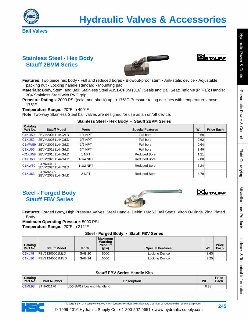
Stainless Steel - Hex Body Stauff 2BVM Series
Features: Two piece hex body • Full and reduced bores • Blowout-proof stem • Anti-static device • Adjustable packing nut • Locking handle standard • Mounting pad
Materials: Body, Stem, and Ball: Stainless Steel A351-CF8M (316); Seals and Ball Seat: Teflon® (PTFE); Handle: 304 Stainless Steel with PVC grip
Preasure Ratings: 2000 PSI (cold, non-shock) up to 175°F. Pressure rating declines with temperature above 175°F.
Temperature Range: -20°F to 400°F Note: Two-way Stainless Steel ball valves are designed for use as an on/off device.
Stainless Steel - Hex Body • Stauff 2BVM SeriesCatalog Part No. Stauff Model Ports Special Features Wt. Price Each
C1KU50 2BVM20041144C/LD 1/4 NPT Full bore 0.60
C1KU52 2BVM20061144G/LD 3/8 NPT Full bore 0.62
C1MW59 2BVM20081144G/LD 1/2 NPT Full bore 0.64
C1KU56 2BVM20121144G/LD 3/4 NPT Full bore 1.40
•C1KU58 2BVM20161144G/LD 1 NPT Reduced Bore 1.21
C1KU60 2BVM20201144G/LD 1-1/4 NPT Reduced Bore 2.80
C1KW60 STNA30121 2BVM20241144C/LD 1-1/2 NPT Reduced Bore 3.24
C1KU63 STNA32685 2BVM20321144G-LD 2 NPT Reduced Bore 4.70
Steel - Forged Body Stauff FBV Series
Features: Forged Body, High Pressure Valves. Steel Handle. Delrin +MoS2 Ball Seats. Viton O-Rings. Zinc Plated Body.
Maximum Operating Pressure: 5000 PSI Temperature Range: -20°F to 212°F
Steel - Forged Body • Stauff FBV Series
Catalog Part No. Stauff Model Ports
Maximum Working Pressure
(psi) Special Features Wt.Price Each
C1KL79 FBV21200001MLD SAE-20 5000 Locking Device 8.60
C1KL80 FBV21240001M/LD SAE-24 5000 Locking Device 3.25
Stauff FBV Series Handle KitsCatalog Part No. Part Number Description Wt.
Price Each
C1ML98 STNA31170 LD6-SW17 Locking Handle Kit 0.38
Ball Valves

This page is part of a complete catalog which contains technical and safety data that must be reviewed when selecting a product
Hydraulic Valves & Accessories
Hyd
raul
ic P
ower
& C
ontr
olP
neum
atic
Pow
er &
Con
trol
Flu
id C
onve
ying
Mis
cella
neou
s P
rodu
cts
Inde
xes
& T
echn
ical
Info
rmat
ion
246 1999-2016 Hydraulic Supply Co. • 1-800-507-9651 • www.hydraulic-supply.com
Apollo® Ball Valve Seal Kits
Apollo® Ball Valve • Seal KitsCatalog Part No. Apollo Model Description Wt.
Price Each
C1EN75 70-008-01 70-100, 70-800, 73-100 Series (2 in. size). 77-100 Series (1-1/2 in size). 70-600 Series (2 in. size). 0.12
Ball Valves

Hydraulic Valves & Accessories
This page is part of a complete catalog which contains technical and safety data that must be reviewed when selecting a product
Hydraulic P
ower &
Control
Pneum
atic Pow
er & C
ontrolF
luid Conveying
Miscellaneous P
roductsIndexes &
Technical Information
247 1999-2016 Hydraulic Supply Co. • 1-800-507-9651 • www.hydraulic-supply.com
Inline Check Valves For Hydraulic (To 12 GPM) & Pneumatic Service
Features: Low pressure differential required to open & close. Application: Free flow is permitted in the direction of the arrow; positive check in the opposite direction. Brass
valves for use in pneumatic systems and lower pressure hydraulic systems. Steel valves for use in hydraulic systems. Pressure ratings in tables are for non-shock service.
Materials: Body: Available in Brass, Carbon Steel or Stainless Steel.
Inline Check Valves • For Hydraulic (To 12 GPM) & Pneumatic Service
Catalog Part No. Deltrol Model Size Threads
Body Material
Maximum Operating Pressure
Non-Shock (psi)
Flow Rating (GPM)
CV Factor
Cracking Pressure
(PSI)A
(in)C
(in)E
(in) Wt.Price Each
•C1CM26 C20B 1/4 1/4-18 NPT Brass 2000 3.0 0.54 1 to 2.5 .88 0.36 2.00 0.36
C1CM36 C30B 1/2 1/2-14 NPT Brass 2000 8.0 1.47 1 to 2.5 1.31 0.47 2.66 0.89
Inline Check Valves For Water, Steam, Oil, Chemicals
Features: Fully-formed stainless steel poppet, metal-to-metal seal, ruggedly constructed. Less than 1 psi cracking pressure. No o-rings are used.
Application: For a wide variety of applications, including hot water, cold water, steam, oil, gas, compounds and chemicals. Not for air compressor service.
Materials: Cast brass 1-piece body, stainless steel poppet. Maximum Working Pressure: 200 lbs. WOG, 75 lbs. steam. Maximum Operating Temperature: 300°F.
Inline Check Valves • For Water, Steam, Oil, ChemicalsCatalog Part No. Strataflo Model Size Ports
CV Factor Dimensions (in) Wt.
Price Each
•C1JR70 400-050 1/2 1/2-14 NPT 2.60 1.40 Diameter, 2.69 Long 0.65
Check Valves

This page is part of a complete catalog which contains technical and safety data that must be reviewed when selecting a product
Hydraulic Valves & Accessories
Hyd
raul
ic P
ower
& C
ontr
olP
neum
atic
Pow
er &
Con
trol
Flu
id C
onve
ying
Mis
cella
neou
s P
rodu
cts
Inde
xes
& T
echn
ical
Info
rmat
ion
248 1999-2016 Hydraulic Supply Co. • 1-800-507-9651 • www.hydraulic-supply.com
Inline Check Valves For Hydraulic (To 55 GPM) & Pneumatic Service
Features: High flow rating. Low pressure differential required to open & close. Application: Free flow is permitted in the direction of the arrow; positive check in the opposite direction. Brass
valves for use in pneumatic systems and lower pressure hydraulic systems. Steel valves for use in hydraulic systems. Pressure ratings in tables are for non-shock service.
Materials: Body: Available in Brass, carbon steel or stainless steel (1" size available in naval bronze or ductile iron). Ball and Spring: Stainless steel. Ball Follower: Delrin. Retainer: Stainless steel.
Maximum Operating Temperature: 200°F.
Inline Check Valves • For Hydraulic (To 55 GPM) & Pneumatic Service
Catalog Part No. Deltrol Model Size Threads
Body Material
Maximum Operating Pressure
Non-Shock (psi)
Flow Rating (GPM)
CV Factor
Cracking Pressure
(PSI)E
(in) F (in) Wt.Price Each
•C1CN88 EC10B 1/8 1/8-27 NPT Brass 2000 3.0 0.75 1 to 2.5 0.63 1.69 0.15
•C1CN89 EC20B 1/4 1/4-18 NPT Brass 2000 6.0 1.47 1 to 2.5 0.75 2.00 0.22
•C1CN90 EC20S 1/4 1/4-18 NPT Steel 5000 6.0 1.47 1 to 2.5 0.75 2.00 0.20
•C1CN93 EDC25B 3/8 3/8-18 NPT Brass 2000 10.0 3.30 1 to 2.5 1.00 2.50 0.49
•C1CN94 EDC25S 3/8 3/8-18 NPT Steel 5000 10.0 3.30 1 to 2.5 1.00 2.50 0.45
•C1CN95 EDC30B 1/2 1/2-14 NPT Brass 2000 12.0 3.60 1 to 2.5 1.13 2.88 0.65
•C1CN96 EDC30S 1/2 1/2-14 NPT Steel 5000 12.0 3.60 1 to 2.5 1.13 2.88 0.59
•C1CN97 EDC35B 3/4 3/4-14 NPT Brass 2000 20.0 5.41 1 to 2.5 1.38 3.25 0.98
•C1CN98 EDC35S 3/4 3/4-14 NPT Steel 5000 20.0 5.41 1 to 2.5 1.38 3.25 0.98
•C1CN92 EC40S 1 1-11-1/2 NPT Steel 5000 55.0 9.60 3 to 5 1.75 4.50 2.48
Check Valves

Hydraulic Valves & Accessories
This page is part of a complete catalog which contains technical and safety data that must be reviewed when selecting a product
Hydraulic P
ower &
Control
Pneum
atic Pow
er & C
ontrolF
luid Conveying
Miscellaneous P
roductsIndexes &
Technical Information
249 1999-2016 Hydraulic Supply Co. • 1-800-507-9651 • www.hydraulic-supply.com
Inline Check Valves (Male Threads) For Hydraulic (To 15 GPM) & Pneumatic Service
Features: Soft seat for bubble-tight seal (CMMO & CMMQ models). Compact overall length. Low pressure differential required to open & close.
Application: Free flow is permitted in the direction of the arrow; positive check in the opposite direction. Brass valves for use in pneumatic systems and lower pressure hydraulic systems. Steel valves for use in hydraulic systems. Pressure ratings in tables are for non-shock service.
Materials: Body: Available in Brass, Carbon Steel or Stainless Steel. Ball: Stainless steel. Retainer: Stainless steel.
Operating Temperature Range: -30°F to 250°F (Soft seat CMMO & CMMQ models).
Inline Check Valves (Male Threads) • For Hydraulic (To 15 GPM) & Pneumatic Service
Catalog Part No. Deltrol Model Size Threads
Body Material
Maximum Operating Pressure
Non-Shock (psi)
Flow Rating (GPM)
CV Factor
Cracking Pressure
(PSI)A
(in)B
(in) Wt.Price Each
•C1CN38 CMMQ20B 1/4 1/4-18 NPT Brass 2000 2.5 0.56 1 to 2.5 1.38 0.63 0.08
•C1CN39 CMMQ20S 1/4 1/4-18 NPT Steel 3000 2.5 0.56 1 to 2.5 1.38 0.63 0.08
•C1CN40 CMMQ30B 1/2 1/2-14 NPT Brass 1000 10.0 2.71 1 to 2.5 2.06 0.88 0.22
Note: CMMO and CMMQ models have soft seat. CMM models have metal-to-metal seat.
Check Valves

This page is part of a complete catalog which contains technical and safety data that must be reviewed when selecting a product
Hydraulic Valves & Accessories
Hyd
raul
ic P
ower
& C
ontr
olP
neum
atic
Pow
er &
Con
trol
Flu
id C
onve
ying
Mis
cella
neou
s P
rodu
cts
Inde
xes
& T
echn
ical
Info
rmat
ion
250 1999-2016 Hydraulic Supply Co. • 1-800-507-9651 • www.hydraulic-supply.com
Cartridge Type Check Valve Vickers® CV13-10 Series • To 5000 PSI & 20 GPM
Description: This is a compact poppet type check valve ideal for use in manifolds for load sense or low flow applications.
Operation: The valve remains closed until the spring bias is reached at port 1 at which time the poppet lifts of the seat and allows flow from port 1 to port 2. in the other direction the valve is closed.
Rated Flow: 20 GPM. Maximum Operating Pressure: 5000 PSI. Temperature Range: –40° to 248° F Recommended Filtration Level: ISO 4406 Cleanliness Level 18/16/13 or cleaner. Internal Leakage: 5 drops/min. maximum @ 5000 psi. Cartridge: Model CV13-10-*, sold separately. Housing: Cavity Size C-10-2, sold separately, see page 441
Cartridge Type Check Valve • Vickers® CV13-10 Series • To 5000 PSI & 20 GPMCatalog Part No.
Vickers Part No. Vickers Model Cracking Pressure (psi) Housing Seal Material Wt. Price Each
C1MG21 02-200444 CV13-10-P-0-210 210 None Buna-N 0.17
Check Valves

Hydraulic Valves & Accessories
This page is part of a complete catalog which contains technical and safety data that must be reviewed when selecting a product
Hydraulic P
ower &
Control
Pneum
atic Pow
er & C
ontrolF
luid Conveying
Miscellaneous P
roductsIndexes &
Technical Information
251 1999-2016 Hydraulic Supply Co. • 1-800-507-9651 • www.hydraulic-supply.com
Cartridge Type Check Valves Vickers® CV1-16 Series • To 3000 PSI & 40 GPM
Application: Used in hydraulic applications to allow free flow of fluid in one direction only. Rated Flow: 40 GPM. Maximum Operating Pressure: 3000 PSI. Temperature Range: -40°F to 248°F (Extreme Limits). Recommended Filtration Level: ISO 4406 Cleanliness Level 18/16/13 or cleaner. Cartridge: Model CV1-16*, sold separately. Housing: Cavity size C-16-2, sold separately, see page 441
Cartridge Type Check Valves • Vickers® CV1-16 Series • To 3000 PSI & 40 GPMCatalog Part No. Vickers Part No. Vickers Model
Cracking Pressure (psi) Seal Material Wt.
Price Each
C1MG58 565973 CV1-16-P-0-20 20 Buna-N 0.58
Housing Types: Aluminum STD (Standard light-duty aluminum 3000 psi maximum). Aluminum FR (Fatigue-rated aluminum 3000 psi maximum). Steel (Fatigue-rated Steel 5000 psi maximum).
Cartridge Type Check Valves Eaton 3CA300 Series • To 5000 PSI & 80 GPM
Application: Used in hydraulic applications to allow free flow of fluid in one direction only. Rated Flow: 80 GPM. Maximum Operating Pressure: 5000 PSI Temperature Range: –22° to 194°F Recommended Filtration Level: Cleanliness level 18/13 or better. Cartridge: Model 3CA300-*, sold separately. Housing: Cavity size A13245, sold separately, see page 441
Cartridge Type Check Valves • Eaton 3CA300 Series • To 5000 PSI & 80 GPMCatalog Part No. Eaton Part No. Eaton Model Cracking Pressure (psi) Housing Seal Material Wt. Price Each
C1MG47 401AA00180A 3CA300-0.3S 4.4 None Nitrile 1.06
Check Valves
This page is part of a complete catalog which contains technical and safety data that must be reviewed when selecting a product
Hydraulic Valves & Accessories
Hyd
raul
ic P
ower
& C
ontr
olP
neum
atic
Pow
er &
Con
trol
Flu
id C
onve
ying
Mis
cella
neou
s P
rodu
cts
Inde
xes
& T
echn
ical
Info
rmat
ion
252 1999-2016 Hydraulic Supply Co. • 1-800-507-9651 • www.hydraulic-supply.com
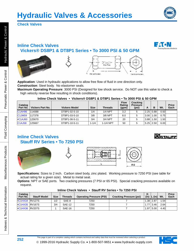
Inline Check Valves Vickers® DS8P1 & DT8P1 Series • To 3000 PSI & 50 GPM
Application: Used in hydraulic applications to allow free flow of fluid in one direction only. Construction: Steel body. No elastomer seals. Maximum Operating Pressure: 3000 PSI (Designed for low shock service. Do NOT use this valve to check a
high velocity reverse flow resulting in shock conditions).
Inline Check Valves • Vickers® DS8P1 & DT8P1 Series • To 3000 PSI & 50 GPM
Catalog Part No. Vickers Part No. Vickers Model Size Threads
Flow Rating (gpm)
Cracking Pressure
(psi) A B Wt.Price Each
C1AH96 114088 DT8P1-02-5-10 1/4 1/4 NPT 3.2 5 2.25 0.88 0.50
C1JM59 117378 DT8P1-03-5-10 3/8 3/8 NPT 8.0 5 3.00 1.00 0.75
•C1AJ60 125670 DT8P1-06-5-11 3/4 3/4 NPT 20 5 3.88 1.50 1.50
C1AJ58 125667 DT8P1-10-5-11 1-1/4 1-1/4 NPT 50 5 5.25 2.50 6.00
Inline Check Valves Stauff RV Series • To 7250 PSI
Specifications: Sizes to 2 inch. Carbon steel body, zinc plated. Working pressure to 7250 PSI (see table for actual rating for a given size). Metal to metal seat.
Options: NPT or SAE ports. Two cracking pressures (7 PSI or 65 PSI). Special cracking pressures available on request.
Inline Check Valves • Stauff RV Series • To 7250 PSICatalog Part No. Stauff Model Size Threads Operating Pressure (PSI) Cracking Pressure (psi)
D (in) L (in) Wt.
Price Each
•C1HX34 RV127S 1/2 SAE-8 7250 7 1.38 2.87 1.54
•C1HX35 RV167S 3/4 SAE-12 7250 7 1.77 3.46 2.64
•C1HX36 RV207S 1 SAE-16 7250 7 1.97 5.00 4.40
Check Valves

Hydraulic Valves & Accessories
This page is part of a complete catalog which contains technical and safety data that must be reviewed when selecting a product
Hydraulic P
ower &
Control
Pneum
atic Pow
er & C
ontrolF
luid Conveying
Miscellaneous P
roductsIndexes &
Technical Information
253 1999-2016 Hydraulic Supply Co. • 1-800-507-9651 • www.hydraulic-supply.com
Inline Check Valves DMIC CVH Series • To 10,000 PSI (At Reduced Safety Factor)
Features: Capable of sustained high pressure operation to 10,000 PSI (Smaller sizes, with reduced safety factor). The precision ground seat and hardened poppet check element eliminate leakage. Superior check valve retainer design prevents spring from fully packing, thereby softening the opening impact and extending service life.
Construction: Allow steel body and piston. Black oxide coating on body. Precision hard seat piston seal. High strength spring steel spring.
Inline Check Valves • DMIC CVH Series • To 10,000 PSI (At Reduced Safety Factor)
Catalog Part No. DMIC Model Size Threads
Flow Rating (GPM @ 300 PSI Drop)
Working Pressure
(psi)
Minimum Burst
Pressure (psi)
C (in)
D (in) Wt.
Price Each
•C1EK50 CVH05-1000N 1 1 NPT 158 6,000 19,500 4.27 1.81 2.13
C1EK51 CVH05-1250-N 1-1/4 1-1/4 NPT 200 6,000 19,500 4.88 2.17 3.42
CAUTION: The manufacturer's pressure and flow ratings are extremely liberal and should be interpreted with caution (Low safety factors are used on pressure ratings, and high pressure drops are used on flow ratings).
Check Valves

This page is part of a complete catalog which contains technical and safety data that must be reviewed when selecting a product
Hydraulic Valves & Accessories
Hyd
raul
ic P
ower
& C
ontr
olP
neum
atic
Pow
er &
Con
trol
Flu
id C
onve
ying
Mis
cella
neou
s P
rodu
cts
Inde
xes
& T
echn
ical
Info
rmat
ion
254 1999-2016 Hydraulic Supply Co. • 1-800-507-9651 • www.hydraulic-supply.com
Right Angle Check Valves Vickers® C2-8 Series • To 3000 PSI • To 100 GPM
Right Angle Check Valves are designed for higher flows with less pressure drop. The valves' seat and poppet are of hardened and ground steel for improved cycle life.
Maximum Operating Pressure: 3000 PSI.
Right Angle Check Valves • Vickers® C2-8 Series • To 3000 PSI • To 100 GPM
Catalog Part No.
Vickers Part No.
Vickers Model Ports
Cracking Pressure
(PSI)
Nominal Flow
Rating (GPM)
Apprx Pressure
Drop at Rated Flow (PSI)
Seals & Options Dimensions (in) Wt.
Price Each
C1HH55 094029 C2-815 3/4 NPT 5 16 20 Buna-N A=3.88 B=1.75 C=2.00 D=2.75 E=1.81 F=3.19 5.00
C1HL46 094043 C2-820 1 NPT 5 28 14 Buna-N A=4.56 B=1.84 C=2.25 D=3.25 E=2.25 F=3.88 7.44
Check Valves

Hydraulic Valves & Accessories
This page is part of a complete catalog which contains technical and safety data that must be reviewed when selecting a product
Hydraulic P
ower &
Control
Pneum
atic Pow
er & C
ontrolF
luid Conveying
Miscellaneous P
roductsIndexes &
Technical Information
255 1999-2016 Hydraulic Supply Co. • 1-800-507-9651 • www.hydraulic-supply.com
Subplate/Manifold Mount Check Valves Vickers® C5G & C5GV Series • To 5000 PSI • To 100 GPM
Description: Subplate mounted check valve, allows flow in one direction only. Can be used with hydraulic oils, water-in-oil emulsions and water glycols.
Pressure & Flow Ratings: See table below. Temperature Range: -4°F to 176°F. Recommended Filtration Level: ISO 4406 Cleanliness Level 20/18/15 or cleaner.
Subplate/Manifold Mount Check Valves • Vickers® C5G & C5GV Series • To 5000 PSI • To 100 GPM
Catalog Part No.
Vickers Part No. Vickers Model Nominal Size
Nominal Flow
Rating (gpm)
Pressure Rating (psi)
Cracking Pressure
(psi) SealsOther
Features Wt.Price Each
C1JM54 614374 C5GV-825UG 1-1/4 100 5000 5 Buna-N
Dual Metric/Inch Hold Down Bolt Facility
12.80
C1JM55 614382 C5GV-825UG-S8 1-1/4 100 5000 75 Buna-N
Dual Metric/Inch Hold Down Bolt Facility
12.95
Check Valves

This page is part of a complete catalog which contains technical and safety data that must be reviewed when selecting a product
Hydraulic Valves & Accessories
Hyd
raul
ic P
ower
& C
ontr
olP
neum
atic
Pow
er &
Con
trol
Flu
id C
onve
ying
Mis
cella
neou
s P
rodu
cts
Inde
xes
& T
echn
ical
Info
rmat
ion
256 1999-2016 Hydraulic Supply Co. • 1-800-507-9651 • www.hydraulic-supply.com
Introduction to Pilot-Operated Check Valves (Lock Valves)
Application: Pilot Operated Check Valves (Lock Valves) are designed to lock a cylinder, without leakage, while a control valve is in a neutral position. Lock Valves function as Check Valves, allowing flow to a cylinder and blocking reverse flow until pilot pressure is applied to unlock the circuit. These valves may be used to prevent movement of a load while the pressure source is inactive. A 4-way control valve is required for all lock valve circuits, including single acting cylinders, in order to apply unlocking pressure to the pilot circuit. A control valve with a free-flow (motor) spool should be used on any circuit which includes a lock valve to prevent pressure build-up between the lock valve and the control valve.
Unlocking Pressure (Single Acting Cylinders): Pressure required in the pilot circuit = 25% of the locked pressure.
Unlocking Pressure (Double Acting Cylinders): To unlock Blind End of cylinder, pressure required in the pilot circuit = Blind End Locked Pressure/[4.0 - (Rod End Locked Pressure/((Cyl Area - Rod Area)/Cyl Area)]. To unlock Rod End of cylinder, pressure required in the pilot circuit = Rod End Locked Pressure/[4.0 - (Head End Locked Pressure/((Cyl Area - Rod Area)/Cyl Area)].
Caution: When the rod end of a double acting cylinder is locked, if the rod diameter exceeds approximately 75% of the cylinder diameter, unlocking pressure becomes excessive and a lock valve should not be used.
Important Lock Valve Basics: Always follow catalog recommendations and application directions • Consult with our representative or the factory when in doubt • When applying lock valves to life carrying machines such as boom/utility type equipment, do not separate the valve from the actuator... close-couple the valve to the actuator • Do not use pilot operated check valves in load holding applications where either overrunning loads are possible, or load release speed is critical • Care should be taken to ensure the load is supported by mechanical means when servicing or removing the valve (CAUTION: When servicing the equipment, trapped pressure may be present in the holding valve circuit. Carefully bleed down the trapped pressure before disassembly) • The cylinder and it's seals must be in good condition.
Pilot Operated Check Valves

Hydraulic Valves & Accessories
This page is part of a complete catalog which contains technical and safety data that must be reviewed when selecting a product
Hydraulic P
ower &
Control
Pneum
atic Pow
er & C
ontrolF
luid Conveying
Miscellaneous P
roductsIndexes &
Technical Information
257 1999-2016 Hydraulic Supply Co. • 1-800-507-9651 • www.hydraulic-supply.com
Cartridge Type Single Pilot Operated Check Valves Vickers® SPC2-10 Series • To 3000 PSI & 6 GPM
Application & Operation: See Introduction to Pilot-Operated Check Valves (Lock Valves) at the beginning of this section.
Ratio of Pilot Piston Area to Check Valve Seat Area: 4:1. Rated Flow: 6 GPM. Maximum Operating Pressure: 3000 PSI. Recommended Fluid Temperature Range: -4°F to 150°F (180°F is extreme condition upper limit). Recommended Filtration Level: ISO 4406 Cleanliness Level 18/16/13 or cleaner. Cartridge: Model SPC2-10*, sold separately. Housing: Cavity size C-10-3, sold separately, see page 442
Cartridge Type Single Pilot Operated Check Valves • Vickers® SPC2-10 Series • To 3000 PSI & 6 GPMCatalog Part No. Vickers Part No. Vickers Model
Cracking Pressure (psi) Seal Material Wt.
Price Each
C1EN54 565619 SPC2-10-P-0-25 25 Buna-N 0.22
Note: Housing not included.
Pilot Operated Check Valves

This page is part of a complete catalog which contains technical and safety data that must be reviewed when selecting a product
Hydraulic Valves & Accessories
Hyd
raul
ic P
ower
& C
ontr
olP
neum
atic
Pow
er &
Con
trol
Flu
id C
onve
ying
Mis
cella
neou
s P
rodu
cts
Inde
xes
& T
echn
ical
Info
rmat
ion
258 1999-2016 Hydraulic Supply Co. • 1-800-507-9651 • www.hydraulic-supply.com
Cartridge Type Single Pilot Operated Check Valves Eaton 4CK30 Series • To 5000 PSI & 8 GPM
Application & Operation: See Instruction to Pilot-Operated Check Valves (Lock Valves) at the beginning of section.
Ratio of Pilot Piston to Check Valve Seat Area: 3:1 Rated Flow: 8 GPM Maximum Operating Pressure: 5000 PSI Recommended Fluid Temperature Range: -22° to +194°F Recommended Filtration Level: Cleanliness level 19/13 or better Cartridge: Model 4CK30, sold separately Housing: Cavity Size A6610, sold separately. For single valve housings, see page 442. For dual valve housings,
see page 444
Cartridge Type Single Pilot Operated Check Valves • Eaton 4CK30 Series • To 5000 PSI & 8 GPMCatalog Part No. Eaton Part No. Eaton Model Cracking Pressure (psi) Seal Material Special Features Wt.
Price Each
C1MG43 401AA00001A 4CK301S 29 Nitrile None
Catalog Part No. Part Number Description Wt.
Price Each
C1NA61 AXP13032-02N Cavity Plug for Cavity Size A6610
Pilot Operated Check Valves

Hydraulic Valves & Accessories
This page is part of a complete catalog which contains technical and safety data that must be reviewed when selecting a product
Hydraulic P
ower &
Control
Pneum
atic Pow
er & C
ontrolF
luid Conveying
Miscellaneous P
roductsIndexes &
Technical Information
259 1999-2016 Hydraulic Supply Co. • 1-800-507-9651 • www.hydraulic-supply.com
Inline Single Pilot Operated Check Valves Vickers® SPC1-10 Series • To 3000 PSI & 12 GPM
Application & Operation: See Introduction to Pilot-Operated Check Valves (Lock Valves) at the beginning of this section.
Ratio of Pilot Piston Area to Check Valve Seat Area: 4:1. Rated Flow: 12 GPM. Maximum Operating Pressure: 3000 PSI. Temperature Range: -40°F to 248°F (Extreme Limits). Recommended Filtration Level: ISO 4406 Cleanliness Level 18/16/13 or cleaner. Cracking Pressure: 15 PSI.
Inline Single Pilot Operated Check Valves • Vickers® SPC1-10 Series • To 3000 PSI & 12 GPM
Catalog Part No. Vickers Part No. Vickers Model Valve & Cylinder Port Size
Pilot Port Size
Pilot Piston Seal Seals Wt.
Price Each
•C1DU37 02-161199 SPC1-10-P-6T SAE-6 SAE-4 No Buna-N 1.13
•C1FD38 565875 SPC1-10-P-8T SAE-8 SAE-4 No Buna-N 1.12
Note: These valves are sold as a complete assembly.
Pilot Operated Check Valves

This page is part of a complete catalog which contains technical and safety data that must be reviewed when selecting a product
Hydraulic Valves & Accessories
Hyd
raul
ic P
ower
& C
ontr
olP
neum
atic
Pow
er &
Con
trol
Flu
id C
onve
ying
Mis
cella
neou
s P
rodu
cts
Inde
xes
& T
echn
ical
Info
rmat
ion
260 1999-2016 Hydraulic Supply Co. • 1-800-507-9651 • www.hydraulic-supply.com
Cylinder Port Single Pilot Operated Check Valves Brand PC-50 Series • To 3000 PSI & 16 GPM
Application & Operation: See Introduction to Pilot-Operated Check Valves (Lock Valves) at the beginning of this section.
Ratio of Pilot Piston Area to Check Valve Seat Area: 4:1. Construction: Cast iron body. Chrome alloy steel ball. Delrin check seat. Buna-N O-Rings. Nominal Flow Rating: Varies with size. See table below. Maximum Operating Pressure: 3000 PSI.
Cylinder Port Single Pilot Operated Check Valves • Brand PC-50 Series • To 3000 PSI & 16 GPMCatalog Part No. Brand Model Main Ports Pilot Port Nominal Flow Rating (GPM) Wt.
Price Each
•C1HG65 PC37C 3/8 NPT 1/4 NPT 8 GPM 0.82
•C1EF82 PC-50C 1/2 NPT 1/4 NPT 16 GPM 1.45
Pilot Operated Check Valves

Hydraulic Valves & Accessories
This page is part of a complete catalog which contains technical and safety data that must be reviewed when selecting a product
Hydraulic P
ower &
Control
Pneum
atic Pow
er & C
ontrolF
luid Conveying
Miscellaneous P
roductsIndexes &
Technical Information
261 1999-2016 Hydraulic Supply Co. • 1-800-507-9651 • www.hydraulic-supply.com
Cartridge Type Single Pilot Operated Check Valves Eaton 4CKD90 Series • To 6000 PSI & 24 GPM
Application & Operation: A decompression pilot check can be used in most applications that use a standard pilot operated check. Free flow in one direction and load holding in the other. The decompression feature allows locked-in pressure to decay in a controlled fashion, reducing hydraulic noise and instability caused by the rapid loss of energy from the actuator. The valve is effective in clamping circuits and when used with intensifiers or when there are high load induced pressures.
Pilot Ratio: 25:1 decompression stage, 3:1 main stage Rated Flow: 24 GPM Maximum Operating Pressure: Cylinder Port 1: 6000 psi, Ports 2 & 3: 5000 psi Operating Temperature: -22° to +194°F Recommended Filtrations Level: 18/13 Cartridge: Model 4CKD90, sold seperately Housing: Cavity Size A12336, sold separately. page 442
Cartridge Type Single Pilot Operated Check Valves • Eaton 4CKD90 Series • To 6000 PSI & 24 GPMCatalog Part No. Eaton Part No. Eaton Model Pilot Ratio Seal Material Wt.
Price Each
C1LX24 401AA00006A 4CKD901S3 25:1 Nitrile
Pilot Operated Check Valves

This page is part of a complete catalog which contains technical and safety data that must be reviewed when selecting a product
Hydraulic Valves & Accessories
Hyd
raul
ic P
ower
& C
ontr
olP
neum
atic
Pow
er &
Con
trol
Flu
id C
onve
ying
Mis
cella
neou
s P
rodu
cts
Inde
xes
& T
echn
ical
Info
rmat
ion
262 1999-2016 Hydraulic Supply Co. • 1-800-507-9651 • www.hydraulic-supply.com
Inline Single Pilot Operated Check Valves Vickers® SPC1-16 Series • To 3000 PSI & 40 GPM
Application & Operation: See Introduction to Pilot-Operated Check Valves (Lock Valves) at the beginning of this section.
Ratio of Pilot Piston Area to Check Valve Seat Area: 4:1. Rated Flow: 40 GPM. Maximum Operating Pressure: 3000 PSI. Temperature Range: -40°F to 248°F (Extreme Limits). Recommended Filtration Level: ISO 4406 Cleanliness Level 18/16/13 or cleaner. Cracking Pressure: 20 PSI.
Inline Single Pilot Operated Check Valves • Vickers® SPC1-16 Series • To 3000 PSI & 40 GPM
Catalog Part No. Vickers Part No. Vickers Model Valve & Cylinder Port Size
Pilot Port Size
Pilot Piston Seal Seals Wt.
Price Each
•C1FR18 02-112763 SPC1-16-P-12T SAE-12 SAE-6 No Buna-N 4.17
Note: These valves are sold as a complete assembly.
Pilot Operated Check Valves

Hydraulic Valves & Accessories
This page is part of a complete catalog which contains technical and safety data that must be reviewed when selecting a product
Hydraulic P
ower &
Control
Pneum
atic Pow
er & C
ontrolF
luid Conveying
Miscellaneous P
roductsIndexes &
Technical Information
263 1999-2016 Hydraulic Supply Co. • 1-800-507-9651 • www.hydraulic-supply.com
Cartridge Type Dual Pilot Operated Check Valves with Thermal Relief Eaton 4CKKT Series • To 4350 PSI & 6.6 GPM
Features: Hardened and ground poppet gives excellent flow capability for valve size, positive sealing and long working life. Cartridge construction allows installation in actuators, manifold blocks and Hydraulic Integrated Circuits. Requires a machined C-10-4 cavity or housing for installation.
Application: Pilot check valves allow flow to pass in one direction, with a low pressure drop, then prevent reverse flow until pilot pressure is applied. There are many applications for this valve type, the most common being to lock and hold a cylinder, or another hydraulic actuator, in position. A pilot relief valve will protect the cylinder and hoses from thermal expansion of the hydraulic fluid. See Introduction to Pilot-Operated Check Valves (Lock Valves) at the beginning of this section.
Specifications: 6.6 gpm rated flow. 4350 psi maximum setting. CAUTION: Pressures over 3000 psi require a steel housing. -22° to +194°F operating temperature range. 5 drops per minute max internal leakage between ports 1 and 2. 15 drops per minute max internal leakage between ports 3 and 4. Based on oil temperature of 104°F and 150 SSU.
Recommended Filtration Level: ISO level 18/13 or better. Installation: 22 ft-lbs torque cartridge into cavity. Unrestricted mounting position. For compatible C-10-4 bodies
see page 443
Cartridge Type Dual Pilot Operated Check Valves with Thermal Relief • Eaton 4CKKT Series • To 4350 PSI & 6.6 GPM
Catalog Part No. Eaton Part No. Eaton Model Pilot Ratio
Pressure Setting (psi) Pilot Seal Body
Seal Material Wt.
Price Each
C1JZ75 401AA00011A 4CKKT503S328 3:1 4000 Standard None Nitrile 0.18
Pilot Operated Check Valves

This page is part of a complete catalog which contains technical and safety data that must be reviewed when selecting a product
Hydraulic Valves & Accessories
Hyd
raul
ic P
ower
& C
ontr
olP
neum
atic
Pow
er &
Con
trol
Flu
id C
onve
ying
Mis
cella
neou
s P
rodu
cts
Inde
xes
& T
echn
ical
Info
rmat
ion
264 1999-2016 Hydraulic Supply Co. • 1-800-507-9651 • www.hydraulic-supply.com
Inline Double Pilot Operated Check Valves Vickers® DPC1-10 Series • To 3000 PSI & 12 GPM
Application & Operation: See Introduction to Pilot-Operated Check Valves (Lock Valves) at the beginning of this section.
Ratio of Pilot Piston Area to Check Valve Seat Area: 4:1. Rated Flow: 12 GPM. Maximum Operating Pressure: 3000 PSI. Temperature Range: -40°F to 248°F (Extreme Limits). Recommended Filtration Level: ISO 4406 Cleanliness Level 18/16/13 or cleaner. Cracking Pressure: 15 PSI
Inline Double Pilot Operated Check Valves • Vickers® DPC1-10 Series • To 3000 PSI & 12 GPMCatalog Part No. Vickers Part No. Vickers Model Port Size Pilot Piston Seal
Seal Material Wt.
Price Each
•C1BT61 566314 DPC1-10-P-6T SAE-6 No Buna-N 1.58
Note: These valves are sold as a complete assembly.
Pilot Operated Check Valves

Hydraulic Valves & Accessories
This page is part of a complete catalog which contains technical and safety data that must be reviewed when selecting a product
Hydraulic P
ower &
Control
Pneum
atic Pow
er & C
ontrolF
luid Conveying
Miscellaneous P
roductsIndexes &
Technical Information
265 1999-2016 Hydraulic Supply Co. • 1-800-507-9651 • www.hydraulic-supply.com
Introduction to Counterbalance Valves (Overcenter Valves)
Overview: There are now many types of overcenter or counterbalance valves available to the designer of hydraulically operated machines, each one has its own place and specific benefits to the user. The function of these valves can be divided into three basic groups. 1. Load Holding; where the overcenter valve prevents the movement of a load when the directional valve is in the neutral position. Permitting the use of open center directional valves and negating leakage past the spool of closed centre directional valves. 2. Load Control; where the overcenter valve prevents the actuator running ahead of the pump due to the load induced energy thereby eliminating cavitation in the actuator and loss of control. 3. Load Safety. In the case of hose failure an overcenter valve mounted onto or into an actuator will prevent uncontrolled movement of the load. When a boom is used as a crane then hose failure protection is vital as the loss of load control could cause damage to people or property. Each of these functions is applicable to linear or rotary motion.
Application: Overcenter valves give static and dynamic control of loads by regulating the flow into and out of hydraulic actuators. When installed close to or within an actuator, the overcenter valve will stop runaway in the event of hose burst and if open center directional control valves are used, will allow thermal expansion relief of the hydraulic fluid. The overcenter cartridge is ideal for mounting directly into a cavity machined in the body of the cylinder, motor or rotary actuator. The cartridge can also be mounted directly to the ports via a specifically machined body as part of an integrated circuit or single unit, or contained within one of the standard line bodies. Single overcenter valves are normally used when the load is unidirectional, for example an aerial platform or crane and dual overcenter valves are used for controlling loads in both directions for motor applications or for cylinders going over center.
Back Pressure: Overcenter valves should not be subjected to back pressure, as this will affect performance and can cause unstable operation. If back pressure cannot be avoided, as an option, a vented spring cavity design should be selected.
Operation: The standard overcenter valve can be described as a pilot assisted relief valve with an integral free flow check. The difference between this design of valve and a pilot check is that the check valve will open fully as soon as the pilot pressure is sufficient to open the valve because the only resistance to opening is the pressure locked in to the cylinder port. With an overcenter valve the pilot pressure has to overcome the force of the spring which is reduced by load pressure. This ensures a gradual opening and a metering of the flow as it passes the poppet. Overcenter valves consist of a poppet that seals flow from an actuator, a check element, which permits free flow to the actuator and a pilot section that opens the poppet allowing flow from the actuator at a controlled rate.
Pilot Ratios: Generally, lower pilot ratios consume more energy for load control but provide more stability. Pilot ratios should then be selected to give good controlability with a minimum of energy loss. Overcenter valves are available with various pilot ratios.
Equal Area Valves: The equal area valve is used when pilot pressure must be set independent of any load-induced pressure, such as on a winch with a brake, where brake release pressure must be obtained before motion is allowed.
Pilot Pressure Formula: The check section allows free flow into the actuator then holds and locks the load against movement. The pilot assisted relief valve section will give controlled movement when pilot pressure is applied. For most applications the relief setting should be approximately 1.3 times higher than the maximum load induced pressure. This ensures that with the maximum load on the actuator the valve will remain closed until pilot pressure is applied. The pilot pressure required to open the valve will depend on the pilot ratio that is the ratio between the relief area and the pilot area. The pilot pressure can be calculated: Pilot pressure = (Valve Setting - Load Pressure)/Pilot Ratio. Example: Valve Setting is 4000 PSI. Load Pressure is 1000 PSI. Valve Ratio is 3:1. Pilot Pressure = (4000-1000)/3, resulting in 1000 PSI required to start to move the load.
Counterbalance Valves (Overcenter Valves)

This page is part of a complete catalog which contains technical and safety data that must be reviewed when selecting a product
Hydraulic Valves & Accessories
Hyd
raul
ic P
ower
& C
ontr
olP
neum
atic
Pow
er &
Con
trol
Flu
id C
onve
ying
Mis
cella
neou
s P
rodu
cts
Inde
xes
& T
echn
ical
Info
rmat
ion
266 1999-2016 Hydraulic Supply Co. • 1-800-507-9651 • www.hydraulic-supply.com
Important Holding Valve Basics: Apply in circuits to prevent loads from dropping faster than input flow would allow • Use on the outlet of the controlled device (meter out) • Always follow catalog recommendations and application directions • Consult with our representative or the factory when in doubt • NEVER apply a holding valve with a an unequal area to outriggers or stabilizers • Do not expect motors to hold without mechanical gearing or brakes. Motors have internal clearances which will allow rotation to occur even when the overcenter valve does not leak • When applying overcenter valves to life carrying machines such as boom/utility type equipment, do not separate the valve from the actuator... close-couple the valve to the actuator • Care should be taken to ensure the load is supported by mechanical means when servicing or removing the valve (CAUTION: When servicing the equipment, trapped pressure may be present in the overcenter valve circuit. Carefully bleed down the trapped pressure before disassembly) • When rebuilding machinery, you should replace rather than repair the overcenter valve • The cylinder and it's seals must be in good condition.
Cartridge Type Counterbalance Valves Eaton 1CE20 Series • To 5000 PSI & 5 GPM
Features: The 1CE20 is a 3 port, externally piloted, screw-in cartridge-type counterbalance (overcenter) valve. Requires a machined A22903 cavity or housing for installation.
Application: To control moving loads and prevent load runaway, giving load holding and hose failure safety. See Introduction to Counterbalance (Overcenter) Valves at the beginning of this section.
Pilot Ratios: 3:1 - Best suited for extremely unstable applications such as long booms or flexible frameworks. 4.5:1 - Best suited for applications where load varies and machine structure can induce instability. 8:1 - Best suited for applications where the load remains relatively constant. Specifications: 5 gpm rated flow. 4000 psi max load induced pressure, 5000 psi max relief pressure. CAUTION:
Pressures over 3000 psi require a steel housing. -22° to +194°F operating temperature range. 5 drops per minute max internal leakage. Based on oil temperature of 104°F and 150 SSU.
Recommended Filtration Level: ISO level 18/13 or better. Installation: 30 ft-lbs torque cartridge into cavity. Unrestricted mounting position. Housing: Cavity size A22903, sold separately. For single valve housings, see page 442; For dual valve housings,
see page 444
Cartridge Type Counterbalance Valves • Eaton 1CE20 Series • To 5000 PSI & 5 GPM
Catalog Part No. Eaton Part No. Eaton Model
Pilot Ratio
Adjustment Means
Pressure Range (PSI)
Factory Setting
(psi) BodySeal
Material Wt.Price Each
C1JZ78 406AA00002A 1CE20F35S4 4.5:1 Screw with Locknut 2900-5075 3045
None (Select below)
Nitrile 0.35
Counterbalance Valves (Overcenter Valves)

Hydraulic Valves & Accessories
This page is part of a complete catalog which contains technical and safety data that must be reviewed when selecting a product
Hydraulic P
ower &
Control
Pneum
atic Pow
er & C
ontrolF
luid Conveying
Miscellaneous P
roductsIndexes &
Technical Information
267 1999-2016 Hydraulic Supply Co. • 1-800-507-9651 • www.hydraulic-supply.com
Cartridge Type Counterbalance Valves Eaton 1CE30 Series • To 5000 PSI & 8 GPM
Features: The 1CE30 is a 3 port, externally piloted, screw-in cartridge-type counterbalance (overcenter) valve. Requires a machined A6610 cavity or housing for installation.
Application: To control moving loads and prevent load runaway, giving load holding and hose failure safety. See Introduction to Counterbalance (Overcenter) Valves at the beginning of this section.
Pilot Ratios: 2.5:1 - Best suited for extremely unstable applications such as long booms or flexible frameworks. 5:1 - (standard) Best suited for applications where load varies and machine structure can induce instability. 10:1 - Best suited for applications where the load remains relatively constant. Specifications: 8 gpm rated flow. 4000 psi max load induced pressure, 5000 psi max relief pressure. CAUTION:
Pressures over 3000 psi require a steel housing. -22° to +194°F operating temperature range. 5 drops per minute max internal leakage. Based on oil temperature of 104°F and 150 SSU.
Recommended Filtration Level: ISO level 18/13 or better. Installation: 33 ft-lbs torque cartridge into cavity. Unrestricted mounting position. Housings: Cavity A6610 single valve housings, see page 442; Cavity A6610 dual valve housings, see page 444
Cartridge Type Counterbalance Valves • Eaton 1CE30 Series • To 5000 PSI & 8 GPM
Catalog Part No. Eaton Part No. Eaton Model
Pilot Ratio
Adjustment Means
Pressure Range (PSI)
Factory Setting
(psi) BodySeal
Material Wt.Price Each
C1MG50 406AA00004A 1CE30F35S2 2.5:1 Screw with Locknut 1740-5075 3045 None Nitrile 0.33
C1JZ79 406AA00005A 1CE30F35S5 5:1 Screw with Locknut 1740-5075 3045 None Nitrile 0.41
C1JZ80 406AA00006A 1CE30F35S10 10:1 Screw with Locknut 1740-5075 3045 None Nitrile 0.40
Counterbalance Valves (Overcenter Valves)

This page is part of a complete catalog which contains technical and safety data that must be reviewed when selecting a product
Hydraulic Valves & Accessories
Hyd
raul
ic P
ower
& C
ontr
olP
neum
atic
Pow
er &
Con
trol
Flu
id C
onve
ying
Mis
cella
neou
s P
rodu
cts
Inde
xes
& T
echn
ical
Info
rmat
ion
268 1999-2016 Hydraulic Supply Co. • 1-800-507-9651 • www.hydraulic-supply.com
Cartridge Type Counterbalance Valves Eaton 1CEV30 Series • To 4000 PSI & 8 GPM
Features: The 1CEV30 is a 3 port, externally piloted, pressure balanced screw-in cartridge-type counterbalance (overcenter) valve. Requires a machined C-10-3S cavity or housing for installation.
Application: The pressure balanced valve is unaffected by back pressure, allowing service line reliefs to operate and for the valve to be used in regenerative or proportional valve systems.
Pilot Ratio: 5:1 - (standard) Best suited for applications where load varies and machine structure can induce instability. 7:1 - Best suited for applications where the load remains relatively constant.
Specifications: 8 gpm rated flow. 3000 psi max load induced pressure, 4000 psi max relief pressure. CAUTION: Pressures over 3000 psi require a steel housing. -22° to +194°F operating temperature range. 5 drops per minute max internal leakage. Based on oil temperature of 104°F and 150 SSU.
Recommended Filtration Level: ISO level 18/13 or better. Installation: 33 ft-lbs torque cartridge into cavity. Unrestricted mounting position. Cartridge: Model 1CEV30-*, sold separately. Housing: C-10-3S cavity, sold separately. For single valve housings, see page 442; For dual valve housings, see
page 444
Cartridge Type Counterbalance Valves • Eaton 1CEV30 Series • To 4000 PSI & 8 GPM
Catalog Part No. Eaton Part No. Eaton Model
Control Ratio
Adjustment Style
Adjustment Range (psi)
Pre-Set Pressure
(psi) Housing Seal Material Wt.Price Each
•C1MJ86 406AA02900A 1CEV30-F-20S-5 5:1 Screw 1000-3000 2030 None Viton 0.30
C1MG52 406AA02901A 1CEV30-F-30S-5 5:1 Screw 1450-4000 3500 None Viton 0.30
Counterbalance Valves (Overcenter Valves)

Hydraulic Valves & Accessories
This page is part of a complete catalog which contains technical and safety data that must be reviewed when selecting a product
Hydraulic P
ower &
Control
Pneum
atic Pow
er & C
ontrolF
luid Conveying
Miscellaneous P
roductsIndexes &
Technical Information
269 1999-2016 Hydraulic Supply Co. • 1-800-507-9651 • www.hydraulic-supply.com
Cartridge Type Counterbalance Valves Eaton 1SE30 Series • To 5000 PSI & 8 GPM
Features: The 1SE30 is a 3 port, externally piloted, screw-in cartridge-type counterbalance (overcenter) valve. Requires a machined T11A Sun cavity or housing for installation.
Application: To control moving loads and prevent load runaway, giving load holding and hose failure safety. See Introduction to Counterbalance (Overcenter) Valves at the beginning of this section.
Pilot Ratios: 2.5:1 - Best suited for extremely unstable applications such as long booms or flexible frameworks. 5:1 - (standard) Best suited for applications where load varies and machine structure can induce instability. 10:1 - Best suited for applications where the load remains relatively constant. Specifications: 8 gpm rated flow. 4000 psi max load induced pressure, 5000 psi max relief pressure. CAUTION:
Pressures over 3000 psi require a steel housing. -22° to +194°F operating temperature range. 5 drops per minute max internal leakage. Based on oil temperature of 104°F and 150 SSU.
Recommended Filtration Level: ISO level 18/13 or better. Installation: 33 ft-lbs torque cartridge into cavity. Unrestricted mounting position.
Cartridge Type Counterbalance Valves • Eaton 1SE30 Series • To 5000 PSI & 8 GPM
Catalog Part No. Eaton Part No. Eaton Model
Pilot Ratio
Adjustment Means
Pressure Range (PSI)
Factory Setting
(psi) BodySeal
Material Wt.Price Each
C1JZ83 406AA00049A 1SE30F35S5 5:1 Screw with Locknut 1015-5075 3045 None Nitrile 0.45
Counterbalance Valves (Overcenter Valves)

This page is part of a complete catalog which contains technical and safety data that must be reviewed when selecting a product
Hydraulic Valves & Accessories
Hyd
raul
ic P
ower
& C
ontr
olP
neum
atic
Pow
er &
Con
trol
Flu
id C
onve
ying
Mis
cella
neou
s P
rodu
cts
Inde
xes
& T
echn
ical
Info
rmat
ion
270 1999-2016 Hydraulic Supply Co. • 1-800-507-9651 • www.hydraulic-supply.com
Cartridge Type Counterbalance Valves Eaton 1SE90 Series • To 5000 PSI & 23 GPM
Features: The 1SE90 is a 3 port, externally piloted, screw-in cartridge-type counterbalance (overcenter) valve. Requires a machined T2A Sun cavity or housing for installation.
Application: To control moving loads and prevent load runaway, giving load holding and hose failure safety. See Introduction to Counterbalance (Overcenter) Valves at the beginning of this section.
Pilot Ratios: 4:1 - Best suited for applications where the load remains relatively constant. Specifications: 23 gpm rated flow. 4000 psi max load induced pressure, 5000 psi max relief pressure. CAUTION:
Pressures over 3000 psi require a steel housing. -22° to +194°F operating temperature range. 5 drops per minute max internal leakage. Based on oil temperature of 104°F and 150 SSU.
Recommended Filtration Level: ISO level 18/13 or better. Installation: 44 ft-lbs torque cartridge into cavity. Unrestricted mounting position.
Cartridge Type Counterbalance Valves • Eaton 1SE90 Series • To 5000 PSI & 23 GPM
Catalog Part No. Eaton Part No. Eaton Model
Pilot Ratio
Adjustment Means
Pressure Range (PSI)
Factory Setting
(psi) BodySeal
Material Wt.Price Each
C1JZ85 406AA00054A 1SE90F35S4 4:1 Screw with Locknut 2537-5075 3045 None Nitrile 0.90
Counterbalance Valves (Overcenter Valves)

Hydraulic Valves & Accessories
This page is part of a complete catalog which contains technical and safety data that must be reviewed when selecting a product
Hydraulic P
ower &
Control
Pneum
atic Pow
er & C
ontrolF
luid Conveying
Miscellaneous P
roductsIndexes &
Technical Information
271 1999-2016 Hydraulic Supply Co. • 1-800-507-9651 • www.hydraulic-supply.com
Cartridge Type Counterbalance Valves Eaton 1SEB90 • To 4000 PSI & 23 GPM
Features: The 1SEB90 is a 3 port, externally piloted, screw-in cartridge-type counterbalance (overcenter) valve with a spring chamber vented to atmosphere. Requires a machined T2A Sun cavity or housing for installation.
Application: To control moving loads and prevent load runaway, giving load holding and hose failure safety. This pressure balanced valve is unaffected by back pressure, allowing service line reliefs to operate and for the valve to be used in regenerative or proportional valve systems. See Introduction to Counterbalance (Overcenter) Valves at the beginning of this section.
Pilot Ratios: 4:1 Best suited for applications where the load remains relatively constant. Pressure Rating: Max Relief Setting: 5000 PSI. Max Load Induced Pressure: 4000 PSI Rated Flow: 23 GPM Temperature Range: -22° to +194°F Recommended Filtration Level: 18/13 Cartridge: Model 1SEB90, sold separately Housing: A20092-T2A or Sun T2A, sold separately
Cartridge Type Counterbalance Valves • Eaton 1SEB90 • To 4000 PSI & 23 GPM
Catalog Part No.
Vickers Part No. Vickers Model
Control Ratio
Adjustment Style
Adjustment Range (psi)
Pre-Set Pressure
(psi) HousingSeal
Material Wt. Price Each
C1LX28 406AA00056A 1SEB90F35S4 4:1 Screw 1088-5076 3046 None Nitrile 0.92
Counterbalance Valves (Overcenter Valves)

This page is part of a complete catalog which contains technical and safety data that must be reviewed when selecting a product
Hydraulic Valves & Accessories
Hyd
raul
ic P
ower
& C
ontr
olP
neum
atic
Pow
er &
Con
trol
Flu
id C
onve
ying
Mis
cella
neou
s P
rodu
cts
Inde
xes
& T
echn
ical
Info
rmat
ion
272 1999-2016 Hydraulic Supply Co. • 1-800-507-9651 • www.hydraulic-supply.com
Cartridge Type Counterbalance Valves Eaton 1CE90 Series • To 4000 PSI & 23 GPM
Features: Overcenter valves give static and dynamic control of loads by regulating the flow into and out of hydraulic actuators. The check section allows free flow into the actuator then holds and locks the load against movement. The pilot assisted relief valve section will give controlled movement when pilot pressure is applied.
Application: Single overcenter valves are normally used when the load is unidirectional, for example an aerial platform or crane and dual overcenter valves are used for controlling loads in both directional for motor applications or for cylinders going over center.
Pilot Ratios: 4:1 Best suited for applications where load varies and machine structure can induce instability. 8:1 Best suited for applications where the load remains relatively constant.
Pressure Rating: 5000 PSI (CAUTION: Pressures over 3000 PSI require steel housing) Rated Flow: 23 GPM Temperature Range: -22° to +194°F Recommended Filtration Level: 18/13 Cartridge: Model 1CE90, sold separately. Housing: Cavity size A12336, sold separately. page 442
Cartridge Type Counterbalance Valves • Eaton 1CE90 Series • To 4000 PSI & 23 GPM
Catalog Part No. Eaton Part No. Eaton Model
Control Ratio
Adjustment Style
Adjustment Range (psi)
Pre-Set Pressure
(psi) Housing Seal Material Wt. Price Each
C1LX27 406AA00016A 1CE90F35S4 4:1 Screw 2900-5076 3045 None Nitrile 0.63
Counterbalance Valves (Overcenter Valves)

Hydraulic Valves & Accessories
This page is part of a complete catalog which contains technical and safety data that must be reviewed when selecting a product
Hydraulic P
ower &
Control
Pneum
atic Pow
er & C
ontrolF
luid Conveying
Miscellaneous P
roductsIndexes &
Technical Information
273 1999-2016 Hydraulic Supply Co. • 1-800-507-9651 • www.hydraulic-supply.com
Cartridge Type Counterbalance Valves Eaton 1CEV90 Series • To 4000 PSI & 23 GPM
Features: Overcenter valves give static and dynamic control of loads by regulating the flow into and out of hydraulic actuators. The check section allows free flow into the actuator then holds and locks the load against movement. The pilot assisted relief valve section will give controlled movement when pilot pressure is applied.
Application: Single overcenter valves are normally used when the load is unidirectional, for example an aerial platform or crane and dual overcenter valves are used for controlling loads in both directional for motor applications or for cylinders going over center.
Pilot Ratios: 4:1 Best suited for applications where load varies and machine structure can induce instability. 8:1 Best suited for applications where the load remains relatively constant.
Pressure Rating: 4000 PSI (CAUTION: Pressures over 3000 PSI require steel housing) Rated Flow: 23 GPM Temperature Range: -22° to +194°F Recommended Filtration Level: 18/13 Cartridge: Model 1CEV90, sold separately. Housing: Cavity size C-12-3S, sold separately. page 442
Cartridge Type Counterbalance Valves • Eaton 1CEV90 Series • To 4000 PSI & 23 GPM
Catalog Part No. Eaton Part No. Eaton Model
Control Ratio
Adjustment Style
Adjustment Range (psi)
Pre-Set Pressure
(psi) Housing Seal Material Wt. Price Each
C1MJ88 406AA02959A 1CEV90F20S4 4:1 Screw adjustment 1015 - 3265 1450 None Nitrile 0.92
C1MJ90 406AA02964A 1CEV90F35S8 8:1 Screw adjustment 1450 - 5076 2900 None Nitrile 0.92
Counterbalance Valves (Overcenter Valves)
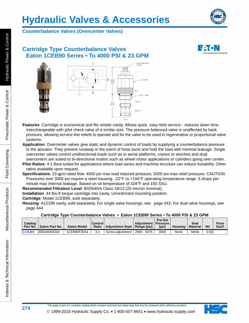
This page is part of a complete catalog which contains technical and safety data that must be reviewed when selecting a product
Hydraulic Valves & Accessories
Hyd
raul
ic P
ower
& C
ontr
olP
neum
atic
Pow
er &
Con
trol
Flu
id C
onve
ying
Mis
cella
neou
s P
rodu
cts
Inde
xes
& T
echn
ical
Info
rmat
ion
274 1999-2016 Hydraulic Supply Co. • 1-800-507-9651 • www.hydraulic-supply.com
Cartridge Type Counterbalance Valves Eaton 1CEB90 Series • To 4000 PSI & 23 GPM
Features: Cartridge is economical and fits simple cavity. Allows quick, easy field service - reduces down time. Interchangeable with pilot check valve of a similar size. The pressure balanced valve is unaffected by back pressure, allowing service line reliefs to operate and for the valve to be used in regenerative or proportional valve systems.
Application: Overcenter valves give static and dynamic control of loads by supplying a counterbalance pressure to the actuator. They prevent runaway in the event of hose burst and hold the load with minimal leakage. Single overcenter valves control unidirectional loads such as in aerial platforms, cranes or winches and dual overcenters are suited to bi-directional motion such as wheel motor applications or cylinders going over center.
Pilot Ratios: 4:1 Best suited for applications where load varies and machine structure can induce instability. Other ratios available upon request.
Specifications: 23 gpm rated flow. 4000 psi max load induced pressure, 5000 psi max relief pressure. CAUTION: Pressures over 3000 psi require a steel housing. -22°F to +194°F operating temperature range. 5 drops per minute max internal leakage. Based on oil temperature of 104°F and 150 SSU.
Recommended Filtration Level: BS5540/4 Class 18/13 (25 micron nominal). Installation: 44 lbs-ft torque cartridge into cavity. Unrestricted mounting position. Cartridge: Model 1CEB90, sold separately. Housing: A12336 cavity, sold separately. For single valve housings, see page 442; For dual valve housings, see
page 444
Cartridge Type Counterbalance Valves • Eaton 1CEB90 Series • To 4000 PSI & 23 GPM
Catalog Part No. Eaton Part No. Eaton Model
Control Ratio Adjustment Style
Adjustment Range (psi)
Pre-Set Pressure
(psi) HousingSeal
Material Wt.Price Each
C1MJ85 406AA00020A 1CEB90F35S4 4:1 Screw adjustment 2900 - 5075 3000 None Nitrile 0.63
Counterbalance Valves (Overcenter Valves)

Hydraulic Valves & Accessories
This page is part of a complete catalog which contains technical and safety data that must be reviewed when selecting a product
Hydraulic P
ower &
Control
Pneum
atic Pow
er & C
ontrolF
luid Conveying
Miscellaneous P
roductsIndexes &
Technical Information
275 1999-2016 Hydraulic Supply Co. • 1-800-507-9651 • www.hydraulic-supply.com
Cartridge Type Counterbalance Valves Eaton 1CE300 Series • To 5000 PSI & 80 GPM
Features: The 1CE300 is a 3 port, externally piloted, screw-in cartridge-type counterbalance (overcenter) valve. Requires a machined A6935 cavity or housing for installation.
Application: To control moving loads and prevent load runaway, giving load holding and hose failure safety. See Introduction to Counterbalance (Overcenter) Valves at the beginning of this section.
Pilot Ratios: 3:1 - Best suited for applications where load varies and machine structure can induce instability. 8:1 - Best suited for applications where the load remains relatively constant. Specifications: 80 gpm rated flow. 4000 psi max load induced pressure, 5000 psi max relief pressure. CAUTION:
Pressures over 3000 psi require a steel housing. -22° to +194°F operating temperature range. 60 drops per minute max internal leakage. Based on oil temperature of 104°F and 150 SSU.
Recommended Filtration Level: ISO level 18/13 or better. Installation: 110 ft-lbs torque cartridge into cavity. Unrestricted mounting position. Housing: Cavity size A6935 sold separately. For single valve housings, see page 442; For dual valve housings,
see page 444
Cartridge Type Counterbalance Valves • Eaton 1CE300 Series • To 5000 PSI & 80 GPM
Catalog Part No. Eaton Part No. Eaton Model
Pilot Ratio
Adjustment Means
Pressure Range (PSI)
Factory Setting
(psi) BodySeal
Material Wt.Price Each
C1JZ82 406AA00031A 1CE300F35S3 3:1 Screw with Locknut 1015-5075 3045
None (Select below)
Nitrile 0.70
Counterbalance Valves (Overcenter Valves)

This page is part of a complete catalog which contains technical and safety data that must be reviewed when selecting a product
Hydraulic Valves & Accessories
Hyd
raul
ic P
ower
& C
ontr
olP
neum
atic
Pow
er &
Con
trol
Flu
id C
onve
ying
Mis
cella
neou
s P
rodu
cts
Inde
xes
& T
echn
ical
Info
rmat
ion
276 1999-2016 Hydraulic Supply Co. • 1-800-507-9651 • www.hydraulic-supply.com
Cushion Valves (Double Relief Valves) Vickers® CRV-10 Series • To 3000 PSI & 20 GPM
Features: Components can be purchased separately, see Note below. Aluminum in-line type housing. Relief cartridges can be removed from the housing without disturbing the plumbing.
Application: Cushion valves are used to provide pressure relief for bi-directional motors and cylinders. (For cylinder applications, cylinder displacement must be equal in both directions for oil to relieve from one side to the other).
Rated Flow: 20 GPM. Maximum Operating Pressure: 3000 PSI. Re-Seat Pressure: 90% of cracking pressure. Temperature Range: -40°F to 248°F (Extreme limits). Recommended Filtration Level: ISO 4406 Cleanliness Level 18/16/13 or better. Note: Components can be purchased separately. One (1) Housing, Two (2) Cartridges and Two (2) Seal Kits are
required to make the cushion valve assembly. For each cartridge, remove the standard back-up ring and install two (2) half-thickness back-up rings, one on each side of o-ring.
Cushion Valves (Double Relief Valves) • Vickers® CRV-10 Series • To 3000 PSI & 20 GPMCatalog Part No. Vickers Part No. Vickers Model Description Wt.
Price Each
C1JR22 02-178481 CRV-10-S-A8T-36/Complete Assembly. Aluminum Housing with SAE-8 Ports, 2ea Relief Cartridges with 600-3600 PSI adjustment range (not for use above 3000 PSI in this application), Adjusting screw with locknut, Buna-N seals.
2.43
•C1ET93 566688 RV3-10-S-0-3/ Relief Cartridge, 50-300 PSI adjustment range, Adjusting screw with locknut, Buna-N seals (2 required per assembly) 0.51
•C1BT34 565568 RV3-10-S-0-36/Relief Cartridge, 600-3600 PSI adjustment range (not for use above 3000 PSI in this application), Adjusting screw with locknut, Buna-N seals (2 required per assembly)
0.53
C1FK22 565806 SK2-10-2 Buna-N Seal Kit (2 required per assembly) 0.01
Note: Components can be purchased separately. One (1) Housing, Two (2) Cartridges and Two (2) Seal Kits are required to make the cushion valve assembly. For each cartridge, remove the standard back-up ring and install two (2) half-thickness back-up rings, one on each side of o-ring.
Cushion Valves

Hydraulic Valves & Accessories
This page is part of a complete catalog which contains technical and safety data that must be reviewed when selecting a product
Hydraulic P
ower &
Control
Pneum
atic Pow
er & C
ontrolF
luid Conveying
Miscellaneous P
roductsIndexes &
Technical Information
277 1999-2016 Hydraulic Supply Co. • 1-800-507-9651 • www.hydraulic-supply.com
Cushion Valves (Double Relief Valves) Cross Series RC • To 3000 PSI & 30 GPM
Features: Cartridge type hydraulically dampened poppet design. Quiet. Smaller differential between cracking and full-flow pressures.
Application: Cross model RC Cushion Valves are designed to protect equal displacement cylinders or motors from external or shock loads. Fluid which passes through one relief valve flows directly to the opposite side or circuit of the valve, thus preventing cavitation of the cylinder or motor as a result of relief discharge. (For cylinder applications, cylinder displacement must be equal in both directions for oil to relieve from one side to the other).
Materials: High tensile gray iron housing. Hardened and ground steel poppet. Buna-N seals. Maximum Flow Rate: 30 GPM Maximum. Maximum Operating Pressure: 3000 PSI.
Cushion Valves (Double Relief Valves) • Cross Series RC • To 3000 PSI & 30 GPMCatalog Part No. Cross Model Port Size Adjustment Type
Adjustment Range (psi)
Pressure Setting (psi) Wt.
Price Each
•C1DJ87 RC12BB 3/4 NPT Screw Adjustment with Acorn Nut 500-1500 1000 4.00
Cushion Valves

This page is part of a complete catalog which contains technical and safety data that must be reviewed when selecting a product
Hydraulic Valves & Accessories
Hyd
raul
ic P
ower
& C
ontr
olP
neum
atic
Pow
er &
Con
trol
Flu
id C
onve
ying
Mis
cella
neou
s P
rodu
cts
Inde
xes
& T
echn
ical
Info
rmat
ion
278 1999-2016 Hydraulic Supply Co. • 1-800-507-9651 • www.hydraulic-supply.com
Cushion Valves (Double Relief Valves) Eaton 1CLLR100 Series • To 5000 PSI & 40 GPM
Features: Single cartridge relieving in both directions cutting down space requirements, giving full adjustment through its range on both pressures at the same time. Requires a machined A878 cavity or housing for installation.
Application: To protect both lines in a circuit from over pressurization by relieving oil to the other line. Ideal for use with motors or directional valves as a safety relief. Differential area, fast acting, poppet valve.
Specifications: 12 gpm rated flow. 3500 psi maximum setting. CAUTION: Pressures over 3000 psi require a steel housing. -22° to +194°F operating temperature range. 0.31 cubic inches per minute max internal leakage. Based on oil temperature of 104°F and 150 SSU. 40 gpm rated flow. 5000 psi maximum setting. CAUTION: Pressures over 3000 psi require a steel housing. -22° to +194°F operating temperature range. 0.31 cubic inches per minute max internal leakage. Based on oil temperature of 104°F and 150 SSU.
Recommended Filtration Level: ISO level 18/13 or better. Installation: 44 ft-lbs torque cartridge into cavity. Unrestricted mounting position.
Cushion Valves (Double Relief Valves) • Eaton 1CLLR100 Series • To 5000 PSI & 40 GPM
Catalog Part No. Eaton Part No. Eaton Model
Pressure Range (PSI)
Factory Setting
(psi)Adjustment
Means BodySeal
Material Wt.Price Each
C1JZ87 407AA00014A 1CLLR100F35S 1650-5075 4060 Screw None Nitrile 0.52
Cushion Valves

Hydraulic Valves & Accessories
This page is part of a complete catalog which contains technical and safety data that must be reviewed when selecting a product
Hydraulic P
ower &
Control
Pneum
atic Pow
er & C
ontrolF
luid Conveying
Miscellaneous P
roductsIndexes &
Technical Information
279 1999-2016 Hydraulic Supply Co. • 1-800-507-9651 • www.hydraulic-supply.com
Valve Housings for 1CLLR100Catalog Part No. Part Number Description Wt.
Price Each
C1LY61 B10623 1CLLR155 Aluminum through ported valve housing; 4 each SAE -12 ports; 3000 PSI max.
Cushion Valves

This page is part of a complete catalog which contains technical and safety data that must be reviewed when selecting a product
Hydraulic Valves & Accessories
Hyd
raul
ic P
ower
& C
ontr
olP
neum
atic
Pow
er &
Con
trol
Flu
id C
onve
ying
Mis
cella
neou
s P
rodu
cts
Inde
xes
& T
echn
ical
Info
rmat
ion
280 1999-2016 Hydraulic Supply Co. • 1-800-507-9651 • www.hydraulic-supply.com
2-Way 2-Position Pull-To-Open Manual Valves Vickers® MPV1-10 Series • To 3000 PSI & 12 GPM
Features: Cartridge style (Requires a machined cavity or housing for installation). Pull-to-open knob. Application: For on-off control of a single stream of fluid. Pull-to-open. Release to close (spring returns valve to closed). Maximum Operating Pressure: 3000 PSI. Rated Flow: 12 GPM. Temperature Range: -40°F to 248°F (Extreme Limits). Recommended Filtration Level: ISO 4406 Cleanliness Level 18/16/13 or cleaner. Cartridge: Model MPV1-10*, sold separately. Housing: Cavity size C-10-2, sold separately, see page 441
2-Way 2-Position Pull-To-Open Manual Valves • Vickers® MPV1-10 Series • To 3000 PSI & 12 GPMCatalog Part No. Vickers Part No. Vickers Model Housing Seal Material Wt.
Price Each
•C1BT36 565589 MPV1-10-K-0 None Buna-N 0.25
Directional Valves, Manually Operated

Hydraulic Valves & Accessories
This page is part of a complete catalog which contains technical and safety data that must be reviewed when selecting a product
Hydraulic P
ower &
Control
Pneum
atic Pow
er & C
ontrolF
luid Conveying
Miscellaneous P
roductsIndexes &
Technical Information
281 1999-2016 Hydraulic Supply Co. • 1-800-507-9651 • www.hydraulic-supply.com
2-Way 2-Position Pull-To-Open Manual Valves Eaton 3CP2 Series • To 3000 PSI & 4 GPM
Features: These cartridges permit a small regulated flow to pass when the hand knob is depressed. Application: A typical application would be on an access platform to lower the boom in the event of a power failure. Maximum Operating Pressure: 3000 PSI. Rated Flow: 0.9 mm orifice 1.4 US gpm, 1.5 mm orifice 4 US gpm. Temperature Range: -22° to 194°F Recommended Filtration Level: Cleanliness level 18/13 or better Cartridge: Model 3CP2*, sold separately. Housing: Cavity size A879, sold separately, see page 441
2-Way 2-Position Pull-To-Open Manual Valves • Eaton 3CP2 Series • To 3000 PSI & 4 GPMCatalog Part No. Eaton Part No. Eaton Model Orifice Size (mm) Flow Rate (GPM) Housing Seals Wt.
Price Each
C1MG46 401AA00053A 3CP2-1.5S 1.5 4 None Nitrile 0.11
Directional Valves, Manually Operated

This page is part of a complete catalog which contains technical and safety data that must be reviewed when selecting a product
Hydraulic Valves & Accessories
Hyd
raul
ic P
ower
& C
ontr
olP
neum
atic
Pow
er &
Con
trol
Flu
id C
onve
ying
Mis
cella
neou
s P
rodu
cts
Inde
xes
& T
echn
ical
Info
rmat
ion
282 1999-2016 Hydraulic Supply Co. • 1-800-507-9651 • www.hydraulic-supply.com
Subplate/Manifold Mount NFPA Size D03 Manual Valves Vickers® DG17V-3 Series • To 5000 PSI & 20 GPM
Features: Subplate mounted. Viton® seals standard. Application: Compact high-pressure manual control valve for double acting cylinders or reversible motors. Maximum Flow Capacity: 20 GPM. Maximum Operating Pressure: 5000 PSI Ports P, A and B. 100 PSI Port T (Intermittent to 1450 PSI) (CAUTION: Need steel subplate or manifold for pressures over 3000 PSI). Recommended Filtration Level: ISO level 18/15 or cleaner.
Mounting Bolts: Standard mounting bolts are (4) 10-24 x 1-1/4 Grade 8 socket head capscrews (Vickers Bolt Kit 590716), torqued to 40-50 lb. in. See Bolt Kits on page 440
Size D03 Subplates & Manifolds: page 450
Subplate/Manifold Mount NFPA Size D03 Manual Valves • Vickers® DG17V-3 Series • To 5000 PSI & 20 GPM
Catalog Part No.
Vickers Part No. Key Vickers Model Type
Spool Action Spool Type Other Features Wt.
Price Each
C1AC70 02-135316 A DG17V-3-6C-60 4-way 3-position
Spring Centered
In Center, P Blocked, A & B to Tank 4.10
Directional Valves, Manually Operated

Hydraulic Valves & Accessories
This page is part of a complete catalog which contains technical and safety data that must be reviewed when selecting a product
Hydraulic P
ower &
Control
Pneum
atic Pow
er & C
ontrolF
luid Conveying
Miscellaneous P
roductsIndexes &
Technical Information
283 1999-2016 Hydraulic Supply Co. • 1-800-507-9651 • www.hydraulic-supply.com
Subplate/Manifold Mount NFPA Size D08 Manual Valves Eaton DG17V-8 Series • Flows to 180 GPM • Pressures to 5000 PSI
Features: Available with a wide variety of spool and spring arrangements. Solid cast iron body and core passages for maximum strength and minimal pressure drop. Maximum Operating Pressures: Ports P, A, B and T: 5000 PSI. (CAUTION: Pressures over 3000 PSI require steel subplate or manifold).
Maximum Flow Rates: Dependent on spool/spring combination. Mounting Considerations: Detented models should mount with longitudinal axis horizontal. Other models may
be mounted in any position. Note: These valves are available in a wide variety of configurations not shown in this catalog. Contact us for
detailed information Size D08 Subplates & Manifolds: Subplates must be ordered seperately. When a subplate is not used, a
machined pad must be provided for mounting. The pad must be flat within 0.0005 in. and smooth within 32 microinch and conform to ISO 4401-08-07-0-94, NFPA T3.5.1 R2-2002 D08.
Subplate/Manifold Mount NFPA Size D08 Manual Valves • Eaton DG17V-8 Series • Flows to 180 GPM • Pressures to 5000 PSI
Catalog Part No.
Eaton Part No. Eaton Model Spool
Flow Rate
(GPM) Seals Wt.Price Each
C1JL60 02-398349 DG17V-8-8N-10-EN588 Tandem spool (P to T in neutral), Open crossover, 3-position detented. (Valve handle not included) 180 Buna-N 32.28
Directional Valves, Manually Operated

This page is part of a complete catalog which contains technical and safety data that must be reviewed when selecting a product
Hydraulic Valves & Accessories
Hyd
raul
ic P
ower
& C
ontr
olP
neum
atic
Pow
er &
Con
trol
Flu
id C
onve
ying
Mis
cella
neou
s P
rodu
cts
Inde
xes
& T
echn
ical
Info
rmat
ion
284 1999-2016 Hydraulic Supply Co. • 1-800-507-9651 • www.hydraulic-supply.com
1-2-3 Spool Monoblock Valves Eaton 30900 Series • To 3000 PSI & 5 GPM
Features: Open Center Parallel Circuit design. Available in single spool, two spool and three spool configurations. Available in a variety of spool types and spool actions. Built-in load checks (not on Motor spools). Available with or without adjustable main relief valve, standard setting 2000 PSI. Application: For general mobile and industrial hydraulic applications. 3-way models control a single acting cylinder or uni-directional motor. 4-way models control a double
acting cylinder or reversible hydraulic motor. Materials: Cast iron bodies. Precision ground induction hardened spools with chrome plating on exposed ends. Pressure Ratings: Rated Pressure: 3000 PSI. Maximum Inlet Pressure: 3500 PSI. Maximum Work Port
Pressure: 4500 PSI. Flow Rating: 5 GPM. Maximum System Temperature: 225°F. Power Beyond: Body is bored for Power Beyond and is plugged. Valves can be converted to Power Beyond (High
Pressure Carryover) with an option kit (31900-321 for SAE-6, 31900-341 for SAE-8). This option allows the installation of another valve downstream from the first valve. Hydraulic oil is available to the downstream valve only when the spool in the upstream valve is in neutral. A separate tank line is required from each control valve.
Closed Center: Valves can be converted to Closed Center with an option kit (31900-319). Dimensions & Technical Information: page 669
1-2-3 Spool Monoblock Valves • Eaton 30900 Series • To 3000 PSI & 5 GPM
Catalog Part No. Eaton Model Spools Spool Type
Power Beyond Work Ports Inlet Port Outlet Port
Spool Action
Relief Setting (PSI) Wt.
Price Each
•C1ES92 30922-DSC 2-Spool
4-way 3-position Tandem Center
Plugged SAE-6 SAE-8 SAE-8 Spring Centered 2000 6.23
Note: Handles are NOT included with valve, and are sold separately.
Parts & Accessories for Eaton 31900 Monoblock Directional ValvesCatalog Part No. Part Number Description Wt.
Price Each
•C1EV79 30950-901 Handle Kit 0.21
Directional Valves, Monoblock

Hydraulic Valves & Accessories
This page is part of a complete catalog which contains technical and safety data that must be reviewed when selecting a product
Hydraulic P
ower &
Control
Pneum
atic Pow
er & C
ontrolF
luid Conveying
Miscellaneous P
roductsIndexes &
Technical Information
285 1999-2016 Hydraulic Supply Co. • 1-800-507-9651 • www.hydraulic-supply.com
1 to 7 Spool Monoblock Valves Salami VDM6 Series • To 5100 PSI &12 GPM
Features: Cast-iron monoblock construction up to 7 spools • Parallel circuit, load check valve protection • Tandem circuit available on first spool of circuit • Venting valve • Power beyond • Hardened steel, nickel-plated spools for higher surface hardness and corrosion resistance • Variety of spool types • Minimum tolerance between the spool and body to obtain a minimum of internal leakage • All spools interchangeable • Variety of spool control and positioning devices Nominal Flow Rating: 12 GPM Maximum Operating Pressure: 5100 PSI on ports "P", "A", & "B" Maximum Back Pressure: 363 PSI
Internal Leakage A/B to T: 1.1 to 1.52 in³/min at 2285 PSI Fluid Temperature Range: -4° to 185°F with NBR seals Ambient Temperature Range: -22°F to 140°F Fluid Viscosity: 10 to 400 cSt; Optimal range 12 to 75 cSt Maximum Level of Contamination: ISO 4406: 19/16 Note: All technical data carried out using mineral oil with viscosity of 16 cSt and contamination level of 19/16 per
ISO 4406 Dimensions & Technical Information: page 691
1 to 7 Spool Monoblock Valves • Salami VDM6 Series • To 5100 PSI &12 GPMCatalog Part No. Salami Model Key Description & (Salami Type Code) Wt.
Price Each
•C1MR75 623100110 ValveValve assy (VDM6/D/U4S) open ctr 1-spool, parallel 4w3p (01A), A&B closed in neutral, protected lever box (NL) on A side, spg ctr (C2) on B side. Direct pressure relief (VS) adj
2190 PSI to 3190 PSI set at 2540 PSI. SAE-8 ports P,A,B; SAE-10 port T.
•C1MR76 623100120 ValveValve assy (VDM6/DD/U4S) open ctr 2-spool, parallel 4w3p (01A), A&B closed in
neutral, lever box (NL) on A side, spg ctr (C2) on B side. Direct pressure relief (VS) adj 2190 PSI to 3190 PSI set at 2540 PSI. SAE-8 ports P,A,B; SAE-10 port T.
•C1MN30 623100130 ValveValve assy (VDM6/DDD/U4S) open ctr 3-spool, parallel 4w3p (01A), A&B closed in
neutral, lever box (NL) on A side, spg ctr (C2) on B side. Direct pressure relief (VS) adj 2190 PSI to 3190 PSI set at 2540 PSI. SAE-8 ports P,A,B; SAE-10 port T.
Directional Valves, Monoblock

This page is part of a complete catalog which contains technical and safety data that must be reviewed when selecting a product
Hydraulic Valves & Accessories
Hyd
raul
ic P
ower
& C
ontr
olP
neum
atic
Pow
er &
Con
trol
Flu
id C
onve
ying
Mis
cella
neou
s P
rodu
cts
Inde
xes
& T
echn
ical
Info
rmat
ion
286 1999-2016 Hydraulic Supply Co. • 1-800-507-9651 • www.hydraulic-supply.com
•C1MR77 623100140 ValveValve assy (VDM6/DDDD/U4S) open ctr 4-spool, parallel 4w3p (01A), A&B closed in
neutral, lever box (NL) on A side, spg ctr (C2) on B side. Direct pressure relief (VS) adj 2190 PSI to 3190 PSI set at 2540 PSI. SAE-8 ports P,A,B; SAE-10 port T.
C1MR78 623100150 ValveValve assy (VDM6/DDDDD/U4S) open ctr 5-spool, parallel 4w3p (01A), A&B closed in neutral, lever box (NL) on A side, spg ctr (C2) on B side. Direct pressure relief (VS) adj
2190 PSI to 3190 PSI set at 2540 PSI. SAE-8 ports P,A,B; SAE-10 port T.
C1MW58 623100160 ValveValve assy (VDM6/DDDDDD/U4S) open ctr 6-spool, parallel 4w3p (01A), A&B closed in neutral, lever box (NL) on A side, spg ctr (C2) on B side. Direct pressure relief (VS) adj
2190 PSI to 3190 PSI set at 2540 PSI. SAE-8 ports P,A,B; SAE-10 port T.
C1MR79 623105500 ValveValve assy (VDM6/DDDDDDD/U4S) open ctr 7-spool, parallel 4w3p (01A), A&B closed
in neutral, lever box (NL) on A side, spg ctr (C2) on B side. Direct pressure relief (VS) adj 2190 PSI to 3190 PSI set at 2540 PSI. SAE-8 ports P,A,B; SAE-10 port T.
C1MQ94 420192000 A side actuator Lever shaft handle with knob and nut M8 x160 mm long
C1MT85 R23100033 A side actuator
Cross lever for 2-spools, 3-position. (L1) fulcrum on upstream spool, (L2) fulcrum on down-stream spool. Accepts M10 threaded handle (not included).
C1MT86 R23100036 A side actuator
Cross lever for 2-spools, one 3-position and one 4-position float spool in. (L2) fulcrum on down-stream spool. Accepts M10 threaded handle (not included).
•C1MU12 R23400060 A side actuator Protected lever positioning kit (NL).
C1MU11 R23400050 A side actuator Spool seal retainer plate (SL)
C1MU93 R360T0600 A side actuator Cable control attachment kit (TC)
C1MU20 R23400322 B side actuator Detent (C0) on each intermediate positions.
C1MU31 R23402000 B side actuator Spool positioning for micro switch (CE). Pre-arrangement for electrical device.
C1MT45 R20288881 B side actuator Spool positioning with microswitch, conversion from (CE) to (CM), IP65.
C1MT43 R20276730 B side actuator Spool positioning with microswitch (CW), IP67 waterproof.
C1MS18 796332550 B side actuator
Electric push-pull control (E7) 3-position, 12 VDC, 31 W, for flows up to 8 GPM, pressures up to 2750 PSI
C1MS20 796332560 B side actuator
Electric push-pull control (E8) 3-position, 24 VDC, 31 W, for flows up to 8 GPM, pressures up to 2750 PSI
C1MS19 796332555 B side actuator
Electric push-pull control (E9) 3-position, 12 VDC, 45 W, for flows up to 10.6 GPM, pressures up to 3050 PSI
C1MT87 R23100080 B side actuator Hydraulic proportional control kit (IP).
C1MU13 R23400100 B side actuator Pneumatic proportional control kit (PP).
C1MU18 R23400320 B side actuator Detent (R2) on positions 1 and 2, spring return to neutral.
C1MU17 R23400280 B side actuator Detent (R4) on position 1, spring return in neutral.
C1MU16 R23400250 B side actuator Detent (R5) on position 2, spring return in neutral.
•C1MU19 R23400321 B side actuator Detent (R9) on positions 1, 2 and neutral.
C1MT37 R20270430 Relief Inlet relief (740 PSI - 1090 PSI)
C1MT38 R20270450 Relief Inlet relief (2190 PSI - 3190 PSI)
C1MT39 R20270460 Relief Inlet relief (3205 PSI - 4785 PSI)
C1MT40 R20270463 Relief Inlet relief (4360 PSI - 5435 PSI)
•C1MT41 R20270471 Relief Inlet relief plug
C1MT88 R23101031 Spool Electric kit safety lever, 12 VDC direct acting, 3-position cylinder spool (01A-ESA-E7)
C1MQ73 323411391 Spool Double acting spool (01A) for "IP" (Hydraulic proportional) control.
C1MQ71 323411307 Spool Double acting spool (01A) for L1/L2 (Cross lever for 2-spools) control (and float spool (01A). A & B blocked in neutral.
1 to 7 Spool Monoblock Valves • Salami VDM6 Series • To 5100 PSI &12 GPMCatalog Part No. Salami Model Key Description & (Salami Type Code) Wt.
Price Each
Directional Valves, Monoblock

Hydraulic Valves & Accessories
This page is part of a complete catalog which contains technical and safety data that must be reviewed when selecting a product
Hydraulic P
ower &
Control
Pneum
atic Pow
er & C
ontrolF
luid Conveying
Miscellaneous P
roductsIndexes &
Technical Information
287 1999-2016 Hydraulic Supply Co. • 1-800-507-9651 • www.hydraulic-supply.com
C1MQ66 323411302 Spool Double acting motor spool (02A), "A" & "B" to tank in neutral.
C1MT89 R23101053 Spool Electric kit with safety lever, 12 VDC direct acting, 3-position motor spool (02A-ESA-E7)
C1MQ74 323411392 Spool Double acting motor spool (02A) for "IP" (Hydraulic proportional) control.
C1MQ69 323411305 Spool Single acting spool (05A), "A" working port. A & B blocked in neutral.
C1MQ70 323411306 Spool Single acting spool (06A), "B" working port. A & B blocked in neutral.
C1MU33 R23480050 Spool Spool kit (12A-NL-F5) includes 4-position float cylinder spool, A-side protected lever box, B-side 3-position spring center 4th-position detent.
C1MU15 R23400210 Spool Spool seal kit
•C1MS13 795429200 Outlet Plug for carry overNote: Handle is NOT included with lever box actuators. Handle must be purchased separately. Abreviations: assy=assembly; ctr=center; 4w3p=4-way, 3-position; spg=spring; adj=adjustable
1 to 7 Spool Monoblock Valves • Salami VDM6 Series • To 5100 PSI &12 GPMCatalog Part No. Salami Model Key Description & (Salami Type Code) Wt.
Price Each
Directional Valves, Monoblock

This page is part of a complete catalog which contains technical and safety data that must be reviewed when selecting a product
Hydraulic Valves & Accessories
Hyd
raul
ic P
ower
& C
ontr
olP
neum
atic
Pow
er &
Con
trol
Flu
id C
onve
ying
Mis
cella
neou
s P
rodu
cts
Inde
xes
& T
echn
ical
Info
rmat
ion
288 1999-2016 Hydraulic Supply Co. • 1-800-507-9651 • www.hydraulic-supply.com
1-Spool Monoblock Valves Walvoil SD4 Series •To 3600 PSI & 12 GPM
Features: Simple, compact design, one-spool valve for open and closed center hydraulic systems • Main pressure relief valve • Optional rotary and detent kick-out controls • Optional cable control • Interchangeable spools. Nominal Flow Rating: 12 GPM. Maximum Operating Pressure: 3600 PSI. Maximum Back Pressure: 360 PSI on outlet port T. Internal Leakage A(B) to T: 0.18 in³/min at 1450 PSI differential pressure. Fluid Temperature Range: -4°F to 176°F with standard Buna-N seals. Ambient Temperature Range: -40°F to 140°F. Viscosity: 80 to 400 SSU Operating, 70 SSU Minimum, 1950 SSU Maximum. Maximum Level of Contamination: ISO 4406 19/16.
Note: Performance data measured with mineral oil of 215 SSU viscosity at 104°F. Dimensions & Technical Information: page 683
1-Spool Monoblock Valves • Walvoil SD4 Series •To 3600 PSI & 12 GPMCatalog Part No. Walvoil Model Key Description & (Walvoil Type Code) Wt.
Price Each
•C1KV96 FVL101100201 (1)Valve assy (SD4/1(KG3)/1CP8L-SAE), P to T in neutral, 4-way, 3-pos, A & B closed in neutral, spg ctr (4), relief (2) adj 900 to 2900 PSI (set at 1750 PSI), std lever box (5) does not include M8 thread handlever (II). SAE-8 ports P & T, SAE-6 ports A & B.
4.50
•C1HV44 FVL101119018 (1)Valve assy (SD4/1SV/68L-SAE), closed ctr, 4-way 3-pos, A & B closed in neutral, spring cent, no rlv. Rlv blanking plug (2), std lever box (5) does NOT include M8 thread handlever (II). SAE-8 ports P & T, SAE-6 ports A & B.
4.43
•C1HV51 FVL5V11104000 (4) "A" side spool positioner (Type 11), with detent in positions 1, neutral and 2 0.26
•C1HX83 FVL5LEV105000 (5) "B" side option (Type L), standard lever box, M8 thread (does NOT include M8 thread handlever) 0.33
•C1AL39 170011012 (II) Handlever (Type AL01/M8x120), for standard leverbox, M8 thread x 120mm long, with black knob 0.10
Directional Valves, Monoblock

Hydraulic Valves & Accessories
This page is part of a complete catalog which contains technical and safety data that must be reviewed when selecting a product
Hydraulic P
ower &
Control
Pneum
atic Pow
er & C
ontrolF
luid Conveying
Miscellaneous P
roductsIndexes &
Technical Information
289 1999-2016 Hydraulic Supply Co. • 1-800-507-9651 • www.hydraulic-supply.com
1 to 7 Spool Monoblock Valves Walvoil SD5 Series •To 4600 PSI & 12 GPM
Features: Simple , compact and heavy duty designed monoblock valves from 1 to 7 sections for open and closed center hydraulic systems.• Fitted with a main pressure relief valve and a load check valve. • Available with parallel, series or tandem circuit. • Optional power beyond port (only for parallel or tandem circuit). • Diameter 0.63 inch interchangeable spools. • A wide variety of service port valve options. • Actuation is manual, pneumatic, electro-pneumatic, hydraulic, electro-hydraulic, with solenoid and remote with flexible cables spool control kits. Nominal Flow Rating: 12 GPM. Maximum Operating Pressure: 4600 PSI (Parallel or Tandem circuit), 3600 PSI (Series circuit). Maximum Back Pressure: 360 PSI on outlet port T.
Internal Leakage A(B) to T: 0.18 in³/min at 1450 PSI differential pressure. Fluid Temperature Range: -4°F to 176°F with standard Buna-N seals. Ambient Temperature Range: -40°F to 140°F. Viscosity: 80 to 400 SSU Operating, 70 SSU Minimum, 1950 SSU Maximum. Maximum Level of Contamination: ISO 4406 19/16. Note: Performance data measured with mineral oil of 215 SSU viscosity at 104°F. Dimensions & Technical Information: page 684
1 to 7 Spool Monoblock Valves • Walvoil SD5 Series •To 4600 PSI & 12 GPMCatalog Part No. Walvoil Model Key Description & (Walvoil Type Code) Wt.
Price Each
•C1AL39 170011012 (II) Handlever (Type AL01/M8x120), for standard leverbox, M8 thread x 120mm long, with black knob 0.10
Directional Valves, Monoblock

This page is part of a complete catalog which contains technical and safety data that must be reviewed when selecting a product
Hydraulic Valves & Accessories
Hyd
raul
ic P
ower
& C
ontr
olP
neum
atic
Pow
er &
Con
trol
Flu
id C
onve
ying
Mis
cella
neou
s P
rodu
cts
Inde
xes
& T
echn
ical
Info
rmat
ion
290 1999-2016 Hydraulic Supply Co. • 1-800-507-9651 • www.hydraulic-supply.com
1 to 6 Spool Monoblock Valves Walvoil SD11 Series •To 4600 PSI & 18 GPM
Features: Simple, compact and heavy duty designed monoblock valves from 1 to 6 spools for open and closed center hydraulic systems • Main pressure relief valve and load check valve • Available with parallel or series circuit • Optional power beyond port (for parallel circuit) • Interchangeable spools • Wide variety of service ports and circuit valves • Spool control kits for manual, pneumatic, hydraulic, electro-hydraulic and remote with flexible cable controls. Nominal Flow Rating: 18 GPM. Maximum Operating Pressure: 4600 PSI (Parallel circuit), 3600 PSI (Series circuit). Maximum Back Pressure: 360 PSI on outlet port T. Internal Leakage A(B) to T: 0.18 in³/min at 1450 PSI differential pressure. Fluid Temperature Range: -4°F to 176°F with standard Buna-N seals. Ambient Temperature Range: -40°F to 140°F.
Viscosity: 80 to 400 SSU Operating, 70 SSU Minimum, 1950 SSU Maximum. Maximum Level of Contamination: ISO 4406 19/16. Note: Performance data measured with mineral oil of 215 SSU viscosity at 104°F. Dimensions & Technical Information: page 687
1 to 6 Spool Monoblock Valves • Walvoil SD11 Series •To 4600 PSI & 18 GPMCatalog Part No. Walvoil Model Key Description & (Walvoil Type Code) Wt.
Price Each
•C1HX82 FVL104130102 (1)
Valve assy (SD11/1-P(KG4-220)/18L/AET-SAE), open ctr 1-spool, parallel 4way3pos A&B closed in neutral spring cent. Dir press rlv (2) 2600-4600 PSI set 3200, std leverbox (5) does NOT include M10 handlever (II). SAE-10 P & T (top outlet), SAE-8 A & B.
13.70
•C1HV54 FVL91110017 (1)
Valve assy (SD11/1-P(KG3)/28L/AET-SAE), open ctr 1-spool, parallel 4way3pos A&B open to tank in neutral, spring cent. Dir press rlv (2) 1150-2900 PSI set 1750, std leverbox (5) does NOT include M10 handlever (II). SAE-10 P & T (top outlet), SAE-8 A & B.
13.59
Directional Valves, Monoblock

Hydraulic Valves & Accessories
This page is part of a complete catalog which contains technical and safety data that must be reviewed when selecting a product
Hydraulic P
ower &
Control
Pneum
atic Pow
er & C
ontrolF
luid Conveying
Miscellaneous P
roductsIndexes &
Technical Information
291 1999-2016 Hydraulic Supply Co. • 1-800-507-9651 • www.hydraulic-supply.com
•C1HV45 FVL104219001 (1)
Valve assy (SD11/2-P(KG3)/18Lx2/AET-SAE) , open ctr 2-spool, parallel 4way3pos A&B closed in neutral spring cent. Dir press rlv (2) 1150-2900 PSI set 1750, std leverboxes (5) does NOT include M10 handlevers (II). SAE-10 P & T (top outlet), SAE-8 A & B.
21.67
•C1HV46 FVL104319004 (1)Valve assy (SD11/3-P(KG3)/18Lx3/AET-SAE), open ctr 3-spool, parallel 4way3pos A&B closed in neutral spring cent. Dir press rlv (2) 1150-2900 PSI set 1750, std leverboxes (5) does NOT include M10 handlevers (II). SAE-10 P & T (top outlet), SAE-8 A & B.
28.80
•C1HT16 3XCAR110213 (2) Direct pressure relief (Type YG3-175), 1800-3600 PSI range, standard setting 2500 PSI. 0.63
C1HZ84 3CU1425130 (3) Spool (Type 2), 4-way 3-position, A & B open to tank in neutral 0.76
•C1HV52 FVL5V11110000 (4) "A" side spool positioner (Type 11), with detent in positions 1, neutral and 2 0.56
•C1JC50 5V08110701 (4) "A" side spool positioner (Type 8P), On/Off pneumatic, NPT 1.41
•C1HV50 FVL3XTAP532450 (6) Outlet port conversion option (Type AEK), closed center plug 0.32
•C1HV49 FVL3XGIU532660 (6) Outlet port conversion option (Type AE), power beyond sleeve, SAE-10 0.38
•C1HQ47 170012020 (II) Handlever (Type AL01/M10x200), for standard leverbox, M10 thread x 200mm long, with black knob 0.28
•C1HQ59 170013025 (II) Handlever (Type AL01/M12x250), for mechanical joystick, M12 thread x 250mm long, with black knob 0.50
1 to 6 Spool Monoblock Valves • Walvoil SD11 Series •To 4600 PSI & 18 GPMCatalog Part No. Walvoil Model Key Description & (Walvoil Type Code) Wt.
Price Each
Directional Valves, Monoblock

This page is part of a complete catalog which contains technical and safety data that must be reviewed when selecting a product
Hydraulic Valves & Accessories
Hyd
raul
ic P
ower
& C
ontr
olP
neum
atic
Pow
er &
Con
trol
Flu
id C
onve
ying
Mis
cella
neou
s P
rodu
cts
Inde
xes
& T
echn
ical
Info
rmat
ion
292 1999-2016 Hydraulic Supply Co. • 1-800-507-9651 • www.hydraulic-supply.com
1-Spool Monoblock Valves Brand AO755 Series •To 3000 PSI & 18 GPM
Features: Small and compact. Positive metering in either direction. Precision ground chrome plated spool for long life. Application: AO755 manually operated valves provide metered flow to either work port. Work port flow is directly proportional to the movement of the lever. The tank port must go directly back to tank. Materials: Cast iron body. Buna-N O-Rings. Chrome plated steel spool. Black nylon ball knob. Maximum Operating Pressure: 3000 PSI. Nominal Flow Rating: 18 GPM.
Recommended Filtration: 30 Micron. Dimensions & Technical Information: page 667
1-Spool Monoblock Valves • Brand AO755 Series •To 3000 PSI & 18 GPMCatalog Part No. Brand Model Key Type
Spool Action
Spool Type Ports Other Features Wt.
Price Each
C1MG87 AO755C4LD C 4-way 3-position Detented Closed
Center3/4NPT Inlet & Outlet 1/2NPT Work Ports No Relief 6.00
C1JC68 AO755-04LF1 A 4-way Friction Detent
Open Center
3/4NPT Inlet & Outlet 1/2NPT Work Ports No Relief 6.19
•C1EK85 AO755-T4-LS D 4-way 3-position
Spring Centered
Tandem Center
3/4NPT Inlet & Outlet 1/2NPT Work Ports No Relief 5.24
•C1HE38 AO755-T4-LD F 4-way 3-position Detented Tandem
Center3/4NPT Inlet & Outlet 1/2NPT Work Ports No Relief 6.00
•C1HE39 AO755-T4-LRS G 4-way 3-position
Spring Centered
Tandem Center
3/4NPT Inlet & Outlet 1/2NPT Work Ports
Adjustable Relief (Set @ 1500 PSI) 6.06
Directional Valves, Monoblock

Hydraulic Valves & Accessories
This page is part of a complete catalog which contains technical and safety data that must be reviewed when selecting a product
Hydraulic P
ower &
Control
Pneum
atic Pow
er & C
ontrolF
luid Conveying
Miscellaneous P
roductsIndexes &
Technical Information
293 1999-2016 Hydraulic Supply Co. • 1-800-507-9651 • www.hydraulic-supply.com
1-Spool Monoblock Valves (Log Splitter Valves) Brand LS755 Series •To 3000 PSI & 18 GPM
Features: Single Hydraulic Kick-Out designed primarily for log splitters. Small and compact. Fine positive metering in either direction. Precision ground chrome plated spool. Application: Spring center hydraulic detent (SHA model) springs back to neutral from one position and pressure release detent in the other direction when the cylinder completes its return stroke. Hydraulic detent in both directions (HHA model, not recommended for log splitters) pressure detent in both directions and springs to center when out of detent. Materials: Cast iron body. Buna-N O-Rings. Brass guide. Chrome plated steel spool.
Black nylon ball knob. Maximum Operating Pressure: 3000 PSI. Nominal Flow Rating: 18 GPM. Recommended Filtration: 30 Micron. Dimensions & Technical Information: page 667
1-Spool Monoblock Valves (Log Splitter Valves) • Brand LS755 Series •To 3000 PSI & 18 GPMCatalog Part No. Brand Model Key Type
Spool Action
Spool Type Ports Other Features Wt.
Price Each
•C1ZU70 LS755T4JRSHA A 4-way 3-position
Log Splitter (See
Below)
Tandem Center
3/4NPT Inlet & Outlet 1/2NPT Work Ports
Adjustable Relief (Set @ 2000 PSI), Adjustable Kick-Out (Set @ 800
PSI)
6.01
Log Splitter Spool Action: Valve is spring centered in one direction (P to B) and has a hydraulic detent release in the other direction (P to A).
Directional Valves, Monoblock

This page is part of a complete catalog which contains technical and safety data that must be reviewed when selecting a product
Hydraulic Valves & Accessories
Hyd
raul
ic P
ower
& C
ontr
olP
neum
atic
Pow
er &
Con
trol
Flu
id C
onve
ying
Mis
cella
neou
s P
rodu
cts
Inde
xes
& T
echn
ical
Info
rmat
ion
294 1999-2016 Hydraulic Supply Co. • 1-800-507-9651 • www.hydraulic-supply.com
1-Spool Monoblock Valves (With Pressure Comp. Flow Control) Brand SDCF Series • To 3000 PSI & 18 GPM
Features: Full range pressure compensated bypass type flow control valve is built in. Pilot operated relief valve is standard. Fine positive metering in either direction. Precision ground chrome plated spool for long life. Application: SDCF valves combine the features of a 4-way directional control valve, a full range pressure compensated by-pass type flow control valve and a pilot operated pressure relief valve all in one compact package. Flow to the work port is directly proportional to the movement of the lever. Flow out of each work port is constant regardless of load changes. The tank port must be plumbed directly back to tank. Materials: Cast iron body. Buna-N O-Rings. Chrome plated steel spool. Maximum Operating Pressure: 3000 PSI. Nominal Flow Rating: 18 GPM. Recommended Filtration: 30 Micron.
Dimensions & Technical Information: page 668
1-Spool Monoblock Valves (With Pressure Comp. Flow Control) • Brand SDCF Series • To 3000 PSI & 18 GPM
Catalog Part No. Brand Model Key Type
Spool Action
Spool Type
Flow Range (GPM) Ports
Other Features Wt.
Price Each
C1MH40 SDCF755M124LF1 4-way 3-position
Friction Detent
Open Center 0-12 3/4NPT Inlet & Outlet
1/2NPT Work PortsAdjustable
Relief 6.50
•C1JD16 SDCF755TM12SLF1 A 4-way 3-position
Friction Detent
Tandem Center 0-12 3/4NPT Inlet & Outlet
1/2NPT Work Ports
Stainless Spool,
Adjustable Relief
7.84
•C1JD15 SDCF755TM124LSSS B 4-way 3-position
Spring Centered
Tandem Center 0-12 3/4NPT Inlet & Outlet
1/2NPT Work Ports
Stainless Spool,
Adjustable Relief
7.83
Option Kits & Parts for Brand SDCF Series ValvesCatalog Part No. Part Number Description Wt.
Price Each
•C1DK84 SDC-S Spring Centering Kit 0.37
C1JB77 SDC-F1 Ball Friction Detent Kit 0.63
Directional Valves, Monoblock

Hydraulic Valves & Accessories
This page is part of a complete catalog which contains technical and safety data that must be reviewed when selecting a product
Hydraulic P
ower &
Control
Pneum
atic Pow
er & C
ontrolF
luid Conveying
Miscellaneous P
roductsIndexes &
Technical Information
295 1999-2016 Hydraulic Supply Co. • 1-800-507-9651 • www.hydraulic-supply.com
1 to 5 Spool Monoblock Valves Salami VDM8 Series • To 5100 PSI & 20 GPM
Features: Cast-iron monoblock construction up to 5 spools • Parallel circuit, load check valve protection • Venting valve • Power beyond • Hardened steel, nickel-plated spools for higher surface hardness and corrosion resistance • Variety of spool types • Minimum tolerance between the spool and body to obtain a minimum of internal leakage • All spools interchangeable • Variety of spool control and positioning devices • Auxiliary valves available on port A/B Nominal Flow Rating: 20 GPM Maximum Operating Pressure: 5100 PSI on ports "P", "A", & "B" Maximum Back Pressure: 363 PSI Internal Leakage A/B to T: 1.52 to 2.13 in³/min at 2285 PSI
Fluid Temperature Range: -4° to 185°F with NBR seals Ambient Temperature Range: -22°F to 140°F Fluid Viscosity: 10 to 400 cSt; Optimal range 12 to 75 cSt Maximum Level of Contamination: ISO 4406: 19/16 Note: All technical data carried out using mineral oil with viscosity of 16 cSt and contamination level of 19/16 per
ISO 4406 Dimensions & Technical Information: page 693
1 to 5 Spool Monoblock Valves • Salami VDM8 Series • To 5100 PSI & 20 GPMCatalog Part No. Salami Model Key Description & (Salami Type Code) Wt.
Price Each
•C1MR80 623200110 ValveSingle spool, monoblock valve (VDM8/02D175/P01A/NPA/C2/U4S), direct acting relief set at 2538 PSI, double acting spool, std. protected lever control, spring centered, SAE
ISO 176 ports (-10 P, -12 T, -10 A&B).
•C1MR81 623200120 Valve2-spool monoblock (VDM8/02D175/2xP01A/NPA/C2/U4S), direct acting relief set at
2538 PSI, double acting spool, std. protected lever control, spring centered, SAE ISO 176 ports (-10 P, -12 T, -10 A&B).
•C1MR82 623200130 Valve3-spool monoblock (VDM8/02D175/3xP01A/NPA/C2/U4S), direct acting relief set at
2538 PSI, double acting spool, std. protected lever control, spring centered, SAE ISO 176 ports (-10 P, -12 T, -10 A&B).
C1MW44 623200140 Valve4-spool monoblock (VDM8/02D175/4xP01A/NPA/C2/U4S), direct acting relief set at
2538 PSI, double acting spool, std. protected lever control, spring centered, SAE ISO 176 ports (-10 P, -12 T, -10 A&B).
Directional Valves, Monoblock

This page is part of a complete catalog which contains technical and safety data that must be reviewed when selecting a product
Hydraulic Valves & Accessories
Hyd
raul
ic P
ower
& C
ontr
olP
neum
atic
Pow
er &
Con
trol
Flu
id C
onve
ying
Mis
cella
neou
s P
rodu
cts
Inde
xes
& T
echn
ical
Info
rmat
ion
296 1999-2016 Hydraulic Supply Co. • 1-800-507-9651 • www.hydraulic-supply.com
C1MR83 623200150 Valve5-spool monoblock (VDM8/02D175/5xP01A/NPA/C2/U4S), direct acting relief set at
2538 PSI, double acting spool, std. protected lever control, spring centered, SAE ISO 176 ports (-10 P, -12 T, -10 A&B).
C1MU90 R360T0200 A side actuator Cable control attachment kit (TC)
•C1MQ95 420290180 A side actuator Lever Handle with knob, M8x180
C1MU43 R23575322 A side actuator Hydraulic Proportional Control Kit (IP), mounts on "A" and "B" side of work section.
C1MU65 R23587640 A side actuator Spool seal retainer (SL)
C1MU48 R23576400 B side actuator Detent Position Kit (C0), detent on each intermediate position.
C1MU46 R23576140 B side actuator Spool Positioning for Micro Switch (CE) for spool 01
C1MT45 R20288881 B side actuator Spool positioning with microswitch, conversion from (CE) to (CM), IP65.
C1MT43 R20276730 B side actuator Spool positioning with microswitch, conversion from (CE) to (CW), IP67 waterproof.
C1MU63 R23587570 B side actuator Cross Lever for 2 spools (L1) fulcrum on up-stream spool
C1MU64 R23587580 B side actuator Cross Lever for 2 spools (L2) fulcrum on up-stream spool
C1MT44 R20287910 B side actuator Standard Protected Lever (NP), lever handle NOT included.
C1MU44 R23575370 B side actuator Pneumatic proportional kit (PP)
C1MU35 R23500300 B side actuator Detent Positioning Kit (R2), Detent on position 1 & 2 with spring return in neutral.
C1MU36 R23500400 B side actuator Dentent Positioning Kit (R4), Detent on position 1 with spring return in neutral.
C1MU37 R23500500 B side actuator Detent Positioning Kit (R5), Detent on position 2 with spring return in neutral.
•C1MU45 R23575490 B side actuator Detent Positioning Kit (R9), Detent on positions 1, 2, and neutral.
C1MS22 796366200 Main relief Main Relief and port relief valve (VA), direct operated, adjustable 290 PSI to 1015 PSI
C1MS23 796366300 Main relief Main Relief and port relief valve (VA), direct operated, adjustable 1030 PSI to 2175 PSI
C1MS24 796366400 Main relief Main Relief and port relief valve (VA), direct operated, adjustable 2190 PSI to 3118 PSI
C1MW43 796366500 Main relief Main Relief and port relief valve (VA), direct operated, adjustable 3130 PSI to 3845 PSI
C1MS25 796366700 Main relief Main Relief and port relief valve (AR), direct operated, adjustable 0 PSI to 6090 PSI
•C1MS15 795429400 Outlet option Plug for carry over for 1 spool valves. Install for power beyond.
•C1MS14 795429300 Outlet option Plug for carry over for 2 to 5 spool valves. Install for power beyond.
C1MT96 R23277620 Port valve Port relief and anti-cavitation valve (AR) kit, non-adjustable, 3000 PSI. Includes plug, seal and fixed setting valve (794129313).
C1MR84 794129301 Port valve Port relief and anti-cavitation valve (AR), non-adjustable, 362 PSI
C1MT90 R23277500 Port valve Port relief and anti-cavitation valve (AR) kit, non-adjustable, 362 PSI. Includes plug, seal and fixed setting valve (794129301).
C1MR85 794129302 Port valve Port relief and anti-cavitation valve (AR), non-adjustable, 464 PSI
C1MR86 794129303 Port valve Port relief and anti-cavitation valve (AR), non-adjustable, 580 PSI
C1MT91 R23277520 Port valve Port relief and anti-cavitation valve (AR) kit, non-adjustable, 580 PSI. Includes plug, seal and fixed setting valve (794129303).
C1MR87 794129304 Port valve Port relief and anti-cavitation valve (AR), non-adjustable, 725 PSI
C1MR88 794129305 Port valve Port relief and anti-cavitation valve (AR), non-adjustable, 910 PSI
C1MT92 R23277540 Port valve Port relief and anti-cavitation valve (AR) kit, non-adjustable, 910 PSI. Includes plug, seal and fixed setting valve (794129305).
1 to 5 Spool Monoblock Valves • Salami VDM8 Series • To 5100 PSI & 20 GPMCatalog Part No. Salami Model Key Description & (Salami Type Code) Wt.
Price Each
Directional Valves, Monoblock
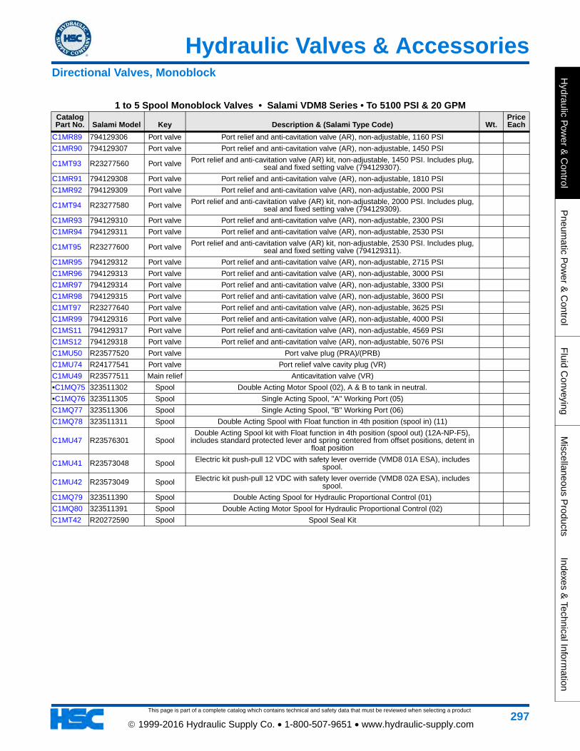
Hydraulic Valves & Accessories
This page is part of a complete catalog which contains technical and safety data that must be reviewed when selecting a product
Hydraulic P
ower &
Control
Pneum
atic Pow
er & C
ontrolF
luid Conveying
Miscellaneous P
roductsIndexes &
Technical Information
297 1999-2016 Hydraulic Supply Co. • 1-800-507-9651 • www.hydraulic-supply.com
C1MR89 794129306 Port valve Port relief and anti-cavitation valve (AR), non-adjustable, 1160 PSI
C1MR90 794129307 Port valve Port relief and anti-cavitation valve (AR), non-adjustable, 1450 PSI
C1MT93 R23277560 Port valve Port relief and anti-cavitation valve (AR) kit, non-adjustable, 1450 PSI. Includes plug, seal and fixed setting valve (794129307).
C1MR91 794129308 Port valve Port relief and anti-cavitation valve (AR), non-adjustable, 1810 PSI
C1MR92 794129309 Port valve Port relief and anti-cavitation valve (AR), non-adjustable, 2000 PSI
C1MT94 R23277580 Port valve Port relief and anti-cavitation valve (AR) kit, non-adjustable, 2000 PSI. Includes plug, seal and fixed setting valve (794129309).
C1MR93 794129310 Port valve Port relief and anti-cavitation valve (AR), non-adjustable, 2300 PSI
C1MR94 794129311 Port valve Port relief and anti-cavitation valve (AR), non-adjustable, 2530 PSI
C1MT95 R23277600 Port valve Port relief and anti-cavitation valve (AR) kit, non-adjustable, 2530 PSI. Includes plug, seal and fixed setting valve (794129311).
C1MR95 794129312 Port valve Port relief and anti-cavitation valve (AR), non-adjustable, 2715 PSI
C1MR96 794129313 Port valve Port relief and anti-cavitation valve (AR), non-adjustable, 3000 PSI
C1MR97 794129314 Port valve Port relief and anti-cavitation valve (AR), non-adjustable, 3300 PSI
C1MR98 794129315 Port valve Port relief and anti-cavitation valve (AR), non-adjustable, 3600 PSI
C1MT97 R23277640 Port valve Port relief and anti-cavitation valve (AR), non-adjustable, 3625 PSI
C1MR99 794129316 Port valve Port relief and anti-cavitation valve (AR), non-adjustable, 4000 PSI
C1MS11 794129317 Port valve Port relief and anti-cavitation valve (AR), non-adjustable, 4569 PSI
C1MS12 794129318 Port valve Port relief and anti-cavitation valve (AR), non-adjustable, 5076 PSI
C1MU50 R23577520 Port valve Port valve plug (PRA)/(PRB)
C1MU74 R24177541 Port valve Port relief valve cavity plug (VR)
C1MU49 R23577511 Main relief Anticavitation valve (VR)
•C1MQ75 323511302 Spool Double Acting Motor Spool (02), A & B to tank in neutral.
•C1MQ76 323511305 Spool Single Acting Spool, "A" Working Port (05)
C1MQ77 323511306 Spool Single Acting Spool, "B" Working Port (06)
C1MQ78 323511311 Spool Double Acting Spool with Float function in 4th position (spool in) (11)
C1MU47 R23576301 SpoolDouble Acting Spool kit with Float function in 4th position (spool out) (12A-NP-F5),
includes standard protected lever and spring centered from offset positions, detent in float position
C1MU41 R23573048 Spool Electric kit push-pull 12 VDC with safety lever override (VMD8 01A ESA), includes spool.
C1MU42 R23573049 Spool Electric kit push-pull 12 VDC with safety lever override (VMD8 02A ESA), includes spool.
C1MQ79 323511390 Spool Double Acting Spool for Hydraulic Proportional Control (01)
C1MQ80 323511391 Spool Double Acting Motor Spool for Hydraulic Proportional Control (02)
C1MT42 R20272590 Spool Spool Seal Kit
1 to 5 Spool Monoblock Valves • Salami VDM8 Series • To 5100 PSI & 20 GPMCatalog Part No. Salami Model Key Description & (Salami Type Code) Wt.
Price Each
Directional Valves, Monoblock

This page is part of a complete catalog which contains technical and safety data that must be reviewed when selecting a product
Hydraulic Valves & Accessories
Hyd
raul
ic P
ower
& C
ontr
olP
neum
atic
Pow
er &
Con
trol
Flu
id C
onve
ying
Mis
cella
neou
s P
rodu
cts
Inde
xes
& T
echn
ical
Info
rmat
ion
298 1999-2016 Hydraulic Supply Co. • 1-800-507-9651 • www.hydraulic-supply.com
Vickers® KDG4V-3 & KDG4V-3S Proportional Valves Without Feedback NFPA Size D03, ISO 4401 Size 03
Description: The primary function of these valves is to direct and meter fluid flow in proportion to current received by the solenoid. This fluid flow controls the velocity, direction and acceleration or deceleration of a cylinder or fluid motor. The valve is controlled by applying current to the coil. This current produces a force at the solenoid push pin which, in turn, causes spool travel. The spool will continue it's motion until the solenoid force is balanced by the
return spring force.Application: These valves are designed to fill the performance gap between conventional solenoid operated
directional valves and servo valves or feedback-type proportional valves. They provide control of spool position and metered fluid flow in applications that don't require the high levels of accuracy, repeatability or response possible with feedback-type proportional valves or servos.
Features: NFPA fatigue rated at 5000 PSI. Fully encapsulated solenoid coils. NEMA 4 rated junction box. Standard Viton® seals.
Nominal Flow Rating: 5.8 GPM (72 PSI pressure drop P to A, 72 PSI pressure drop B to T).Maximum Operating Pressure: 5000 PSI Ports P, A and B. (CAUTION: Pressures over 3000 PSI require steel
subplate or manifold). Port T: 1450 PSI for Standard Performance Valves, 3000 PSI for High Performance Valves.
Operating Temperature Range: -4°F to 180°F.Fluid Viscosity Range: 75 to 250 SSU.Recommended Filtration: ISO 4406 Cleanliness Level 18/16/13 for pressures to 3000 PSI; Level 17/15/12 for
pressures above 3000 PSI.Note: Vickers publication 539 provides the additional technical information necessary for proper application of
these proportional valves. Contact us for application assistance or to request a copy of the Vickers publication.Electronic Accessories (Amplifier Cards, Power Plugs): page 449Size D03 Subplates & Manifolds: page 450Solenoid Connectors: page 446(Required for models that use DIN 43650 coils).Mounting Bolts: Standard mounting bolts are (4) 10-24 x 1-1/4 Grade 8 socket head capscrews (Vickers Bolt Kit
590716 BK590716), torqued to 40-50 lb.in. with threads lubricated. See Bolts Kits on page 440
4-way, 3-position, Spring Centered All Ports Blocked in Center
Spool Flow Rating: P to A or B to T Flow at 72 PSI Pressure Drop. Coil Rating: Current Controlled models are for use with Power Plugs, Amplifier Cards or Joystick Controllers in more demanding applications where current is varied across the coil. Direct Voltage models are for use in less sophisticated and intermittent duty applications where voltage is varied across the coil.
4-way, 3-position, Spring Centered • All Ports Blocked in Center
Catalog Part No.
Vickers Part No. Vickers Model
Spool Flow
Rating (GPM)
Metering Condition
Coil Rating Coil Type Other Features Wt.
Price Each
C1AD14 02-154277 KDG4V-3S-2C08N-H-M-U-H5-60 2.0 Meter In &
Meter Out
24VDC Current
ControlledDIN 43650
STD Performance, 1450 PSI Port T, Waterproof Manual
Override5.00
C1MZ97 820AN00002F KDG4V-3S-2C19N-M-KUP6-G5-60 5.0 Meter In &
Meter Out
12VDC Current
Controlled
Flying Leads
STD Performance, 1450 PSI Port T, Deutsch Connectors
(male)5.00
Directional Valves, Proportional • NFPA Size D03 • ISO 4401 Size 03Vickers KDG4V-3 & KDG4V-3S Series • Without Feedback
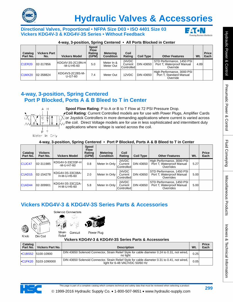
This page is part of a complete catalog which contains technical and safety data that must be reviewed when selecting a product
Hydraulic Valves & Accessories
Hydraulic P
ower &
Control
Pneum
atic Pow
er & C
ontrolF
luid Conveying
Miscellaneous P
roductsIndexes &
Technical Information
299 1999-2016 Hydraulic Supply Co. • 1-800-507-9651 • www.hydraulic-supply.com
C1ER20 02-317856 KDG4V-3S-2C19N-H-M-U-H5-60 5.0 Meter In &
Meter Out
24VDC Current
ControlledDIN 43650
STD Performance, 1450 PSI Port T, Waterproof Manual
Override4.89
C1MX20 02-358824 KDG4V3-2C28S-M-U-G7-60 7.4 Meter Out 12VDC DIN 43650
High Performance, 3000 PSI Port T, Standard Manual
Override
4-way, 3-position, Spring Centered Port P Blocked, Ports A & B Bleed to T in Center
Spool Flow Rating: P to A or B to T Flow at 72 PSI Pressure Drop. Coil Rating: Current Controlled models are for use with Power Plugs, Amplifier Cards or Joystick Controllers in more demanding applications where current is varied across the coil. Direct Voltage models are for use in less sophisticated and intermittent duty applications where voltage is varied across the coil.
4-way, 3-position, Spring Centered • Port P Blocked, Ports A & B Bleed to T in Center
Catalog Part No.
Vickers Part No. Vickers Model
Spool Flow
Rating (GPM)
Metering Condition
Coil Rating Coil Type Other Features Wt.
Price Each
C1JC47 02-311985 KDG4V-3-33C03F-H-M-U-H7-60 0.8 Meter In Only
24VDC Current
ControlledDIN 43650
High Performance, 3000 PSI Port T, Waterproof Manual
Overrides5.27
C1AD15 02-154278 KDG4V-3S-33C08A-H-M-U-H5-60 2.0 Meter In Only
24VDC Current
ControlledDIN 43650
STD Performance, 1450 PSI Port T, Waterproof Manual
Overrides5.00
C1AD44 02-309901 KDG4V-3S-33C22A-H-M-U-H5-60 5.8 Meter In Only
24VDC Current
ControlledDIN 43650
STD Performance, 1450 PSI Port T, Waterproof Manual
Overrides5.00
Vickers KDG4V-3 & KDG4V-3S Series Parts & Accessories
Vickers KDG4V-3 & KDG4V-3S Series Parts & AccessoriesCatalog Part No. Vickers Part No. Description Wt.
Price Each
•C1BS52 5100-10900 DIN 43650 Solenoid Connector, Strain Relief Style for cable diameter 0.24 to 0.31, not wired, no light 0.25
•C1FK20 5103-1090000 DIN 43650 Solenoid Connector, Strain Relief Style for cable diameter 0.31 to 0.41, not wired, light for 6-48 VAC/VDC 50/60 Hz 0.05
4-way, 3-position, Spring Centered • All Ports Blocked in Center
Catalog Part No.
Vickers Part No. Vickers Model
Spool Flow
Rating (GPM)
Metering Condition
Coil Rating Coil Type Other Features Wt.
Price Each
Directional Valves, Proportional • NFPA Size D03 • ISO 4401 Size 03Vickers KDG4V-3 & KDG4V-3S Series • Without Feedback

This page is part of a complete catalog which contains technical and safety data that must be reviewed when selecting a product
Hydraulic Valves & Accessories
Hyd
raul
ic P
ower
& C
ontr
olP
neum
atic
Pow
er &
Con
trol
Flu
id C
onve
ying
Mis
cella
neou
s P
rodu
cts
Inde
xes
& T
echn
ical
Info
rmat
ion
300 1999-2016 Hydraulic Supply Co. • 1-800-507-9651 • www.hydraulic-supply.com
Vickers® KFDG4V-3 Proportional Valves With Feedback NFPA Size D03, ISO 4401 Size 03
Description: The primary function of these valves is to direct and meter fluid flow in proportion to current received by the solenoid. This fluid flow controls the velocity, direction and acceleration or deceleration of a cylinder or fluid motor. The valve is controlled by applying current to the coil. This current produces a force at the solenoid push pin which, in turn, causes spool travel. The spool will continue it's motion until the LVDT's feedback signal balances
with the input signal, ensuring accurate spool position control.Application: These valves are designed to fill the performance gap between non-feedback type proportional
valves and servo valves. They provide control of spool position and metered fluid flow in applications that don't require the highest levels of accuracy, repeatability or response possible with servo valves.
Features: Electronic feedback LVDT ensures accurate spool position control. Internal current feedback provides optimal control. Standard Viton® seals.
Nominal Flow Rating: 5.8 GPM (72 PSI pressure drop P to A, 72 PSI pressure drop B to T).Maximum Operating Pressure: 5000 PSI Ports P, A and B. (CAUTION: Pressures over 3000 PSI require steel
subplate or manifold). Port T: 1500 PSI. (Port L blocked by mounting surface).Maximum Allowable Temperature Ranges: Ambient Air: 140°F. Fluid: 140°F.Fluid Viscosity Range: 70-245 SSU Recommended, 70-2270 SSU Extreme.Recommended Filtration: ISO 4406 Cleanliness Level 18/16/13 for pressures to 3000 PSI; Level 17/15/12 for
pressures above 3000 PSI.Note: Vickers publication 5071.00/EN/0298/A provides the additional technical information necessary for proper
application of these proportional valves. Contact us for application assistance or to request a copy of the Vickers publication.
Electronic Accessories (Amplifier Cards): page 449Size D03 Subplates & Manifolds: page 450Mounting Bolts: Standard mounting bolts are (4) 10-24 x 1-1/4 Grade 8 socket head capscrews (Vickers Bolt Kit
590716 BK590716), torqued to 40-50 lb.in. with threads lubricated. See Bolts Kits on page 440
4-way, 3-position, Spring Centered All Ports Blocked in Center
Spool Flow Rating: P to A or B to T Flow at 72 PSI Pressure Drop. Wiring Connectors: Solenoid coil and LVDT wiring connectors are included with valve. Cable for solenoid coils can range from 0.24-0.40 inch diameter. Cable for LVDT can range from 0.138-0.236 inch diameter.
4-way, 3-position, Spring Centered • All Ports Blocked in Center
Catalog Part No.
Vickers Part No. Vickers Model
Spool Flow
Rating (GPM)
Metering Condition
Coil Rating Coil Type Other Features Wt.
Price Each
C1BT19 565376 KFDG4V-3-2C20N-Z-M-U1-H7-20 5.28 Meter In &
Meter Out
24VDC Amplifier Supplied
DIN 43650 1500 PSI Port T, No Manual Override 6.35
Directional Valves, Proportional • NFPA Size D03 • ISO 4401 Size 03Vickers KFDG4V-3 Series • With Feedback

This page is part of a complete catalog which contains technical and safety data that must be reviewed when selecting a product
Hydraulic Valves & Accessories
Hydraulic P
ower &
Control
Pneum
atic Pow
er & C
ontrolF
luid Conveying
Miscellaneous P
roductsIndexes &
Technical Information
301 1999-2016 Hydraulic Supply Co. • 1-800-507-9651 • www.hydraulic-supply.com
Sectional Control Valves for Open & Closed Center Systems Salami VD6A
Features: Cast-iron bodies • Up to 8 work sections • Parallel, Series, and Tandem circuits with Load Check valve protection on each section • Open and Closed center with Power Beyond options • Spools are hardened steel and nickel-plated • Interchangeable spools • Spool selections: double acting, single acting, motor, cylinder, float, etc. • Auxiliary valves available for ports A and B • Several types of Mid-Inlet modules • Venting valve available • Available Controls: manual, cable, electric, electro-hydraulic, proportional hydraulic, pneumatic, proportional pneumatic, electro-pneumatic.
Nominal Flow Rating: 12 GPM.Maximum Operating Pressure: 5100 PSI on ports P, A, and B.Maximum Back Pressure: 363 PSI on outlet port T.Internal Leakage A(B) to T: 1.1 - 1.52 in³/min. at 2285 PSI.Fluid Temperature Range: -4°F to 185°F with standard NBR seals.Ambient Temperature Range: -22°F to 140°F.Viscosity: 12 cSt to 75 cSt Optimal; 10 cSt minimum, 400 cSt maximum.Maximum Level of Contamination: ISO 4406: 19/16Note: All technical data carried out using mineral oil with viscosity of 16 cSt and contamination level 19/16 as ISO
4406.Dimensions & Technical Information: page 695
VD6A Inlet Module & Options
VD6A Inlet Module & OptionsCatalog Part No. Salami Model Key Description & (Salami Commercial Codes) Wt.
Price Each
C1MU32 R23470090 (1) Inlet module ( /02D175/ ) with direct main pressure relief valve (2) 2200 - 3200 PSI range and standard setting 2540 PSI. SAE -8 end inlet and plugged SAE -8 top inlet.
•C1MT41 R20270471 (2) Inlet relief plug
C1MT37 R20270430 (2) Inlet relief (740 PSI - 1090 PSI)
C1MT38 R20270450 (2) Inlet relief (2190 PSI - 3190 PSI)
Directional Valves, Sectional • Open & Closed CenterSalami VD6A • Flows to 12 GPM (Nominal) • Pressures to 5100 PSI

This page is part of a complete catalog which contains technical and safety data that must be reviewed when selecting a product
Hydraulic Valves & Accessories
Hyd
raul
ic P
ower
& C
ontr
olP
neum
atic
Pow
er &
Con
trol
Flu
id C
onve
ying
Mis
cella
neou
s P
rodu
cts
Inde
xes
& T
echn
ical
Info
rmat
ion
302 1999-2016 Hydraulic Supply Co. • 1-800-507-9651 • www.hydraulic-supply.com
C1MT39 R20270460 (2) Inlet relief (3200 PSI - 4350 PSI)
C1MT40 R20270463 (2) Inlet relief (4360 PSI - 5435 PSI)
VD6A Working Modules & Options
VD6A Working Modules & OptionsCatalog Part No. Salami Model Key Description & (Salami Commercial Codes) Wt.
Price Each
C1MV20 S23480070 (1)Working section (P01A-PRA.PRB-NLA-C2), parallel circuit, 4-way 3-pos. A&B closed in neutral, spring centered to neutral (3), standard protected lever control (4), aux. valve
plugs (5). SAE-8 work ports. Does NOT include M8 threaded handle.
C1MV23 S23480550 (1)Working section (P02A-PRA.PRB-NLA-C2), parallel circuit, 4-way 3-pos. A&B to tank in neutral, spring centered to neutral (3), standard protected lever control (4), aux. valve
plugs (5). SAE-8 work ports. Does NOT include M8 threaded handle.
C1MV24 S23480580 (1)Working section (T01A-PRA.PRB-NLA-C2), tandem circuit, 4-way 3-pos. A & B closed in neutral,spring centered to neutral (3), standard protected lever control (4), aux. valve
plugs (5). SAE-8 work ports. Does NOT include M8 threaded handle.
C1MV22 S23480480 (1)Working section (S01A-PRA.PRB-NLA-C2), series circuit, 4-way 3-pos. A & B closed in
neutral,spring centered to neutral (3), standard protected lever control (4), aux. valve plugs (5). SAE-8 work ports. Does NOT include M8 threaded handle.
C1MV21 S23480270 (1)Working section (P12A-PRA.PRB-NLA-F2), parallel circuit, 4-way 4-pos. A & B closed in neutral, spring centered to neutral, float detent (3), standard protected lever control (4), aux. valve plugs (5). SAE-8 work ports. Does NOT include M8 threaded handle.
C1MW36 S23480542 (1)Working section (P01A-PRA.PRB-ESA-E7B), parallel circuit, 4-way 3-pos. A&B closed in neutral, spring centered direct-electric ON-OFF control 12VDC (3), safety lever (4),
aux. valve plugs (5). SAE-8 work ports.
C1MV25 S23480761 (1)Working section (P02A-PRA.PRB-ESA-E7B), parallel circuit, 4-way 3-pos. A&B to tank in neutral, spring centered direct-electric ON-OFF control 12VDC (3), safety lever (4),
aux. valve plugs (5). SAE-8 work ports.
C1MQ66 323411302 (2) Double acting motor spool (02A), "A" & "B" to tank in neutral.
C1MQ67 323411303 (2) Double acting motor spool (03A), "A" port to tank, "B" port blocked. 24.00
C1MQ68 323411304 (2) Double acting motor spool (04A), "A" port blocked, "B" port to tank. 0.50
C1MQ69 323411305 (2) Single acting spool (05A), "A" working port.
C1MQ70 323411306 (2) Single acting spool (06A), "B" working port. 1.50
C1MQ71 323411307 (2) Double acting spool (01A) for L1/L2 (Cross lever for 2-spools) control (and float spool (01A).
C1MQ73 323411391 (2) Double acting spool (01A) for "IP" (Hydraulic proportional) control.
C1MQ74 323411392 (2) Double acting motor spool (02A) for "IP" (Hydraulic proportional) control.
C1MU18 R23400320 (3) Detent (R2) on positions 1 and 2, spring return to neutral.
C1MU17 R23400280 (3) Detent (R4) on position 1, spring return in neutral.
VD6A Inlet Module & OptionsCatalog Part No. Salami Model Key Description & (Salami Commercial Codes) Wt.
Price Each
Directional Valves, Sectional • Open & Closed CenterSalami VD6A • Flows to 12 GPM (Nominal) • Pressures to 5100 PSI

This page is part of a complete catalog which contains technical and safety data that must be reviewed when selecting a product
Hydraulic Valves & Accessories
Hydraulic P
ower &
Control
Pneum
atic Pow
er & C
ontrolF
luid Conveying
Miscellaneous P
roductsIndexes &
Technical Information
303 1999-2016 Hydraulic Supply Co. • 1-800-507-9651 • www.hydraulic-supply.com
C1MU16 R23400250 (3) Detent (R5) on position 2, spring return in neutral.
C1MU20 R23400322 (3) Detent (C0) on each intermediate positions.
•C1MU19 R23400321 (3) Detent (R9) on positions 1, 2 and neutral.
C1MU31 R23402000 (3) Spool positioning for micro switch (CE). Pre-arrangement for electrical device.
C1MT45 R20288881 (3) Spool positioning with microswitch (CM), IP65.
C1MT43 R20276730 (3) Spool positioning with microswitch (CW), IP67 waterproof.
C1MT87 R23100080 (3) Hydraulic proportional control kit (IP).
C1MU13 R23400100 (3) Pneumatic proportional control kit (PP).
C1MS18 796332550 (3) Electric push-pull control (E7) 3-position, 12 VDC, 31 W, for flows up to 8 GPM, pressures up to 2750 PSI
C1MS19 796332555 (3) Electric push-pull control (E9) 3-position, 12 VDC, 45 W, for flows up to 10.6 GPM, pressures up to 3050 PSI
C1MS20 796332560 (3) Electric push-pull control (E8) 3-position, 24 VDC, 31 W, for flows up to 8 GPM, pressures up to 2750 PSI
•C1MU12 R23400060 (4) Protected lever positioning kit (NL).
C1MQ94 420192000 (4) Lever shaft with knob and nut M8x160
C1MT98 R23400033 (4) Cross lever for 2 spools "L1-L2" fulcrum on up-stream spool
C1MT99 R23400036 (4) Cross lever for 2 spools "L2" double acting spool + float spool in
C1MU11 R23400050 (4) Seal Retainer Plate (SL)
C1MT88 R23101031 (4) Electric kit safety lever, 12 VDC direct acting, 3-position (01A-ESA-E7)
C1MT89 R23101053 (4) Electric kit with safety lever, 12 VDC direct acting, 3-position (02A-ESA-E7)
C1MU22 R23400550 (5) Anti-cavitation port valve (VR).
C1MU93 R360T0600 (4) Cable control actuator (TC)
C1MU83 R25000611 (5) Port relief (VA), adjustable 290 PSI to 1015 PSI
C1MU84 R25000621 (5) Port relief (VA), adjustable 1030 PSI to 1885 PSI
C1MU85 R25000631 (5) Port relief (VA), adjustable 1900 PSI to 2970 PSI
C1MU86 R25000641 (5) Port relief (VA), adjustable 2980 PSI to 4785 PSI
C1MU87 R25001811 (5) Port relief, anticavitation check (AR), adjustable 725 PSI to 1305 PSI
C1MW34 R25001821 (5) Port relief, anticavitation check (AR), adjustable 1320 PSI to 1885 PSI
C1MU88 R25001831 (5) Port relief, anticavitation check (AR), adjustable 1900 PSI to 2975 PSI
C1MW35 R25001841 (5) Port relief, anticavitation check (AR), adjustable 2985 PSI to 3990 PSI
C1MU21 R23400500 (5) Port valve plug (PRA-B).
C1MU15 R23400210 Spool seal kit.
C1MU14 R23400200 Work section side seal kit.
VD6A Working Modules & OptionsCatalog Part No. Salami Model Key Description & (Salami Commercial Codes) Wt.
Price Each
Directional Valves, Sectional • Open & Closed CenterSalami VD6A • Flows to 12 GPM (Nominal) • Pressures to 5100 PSI

This page is part of a complete catalog which contains technical and safety data that must be reviewed when selecting a product
Hydraulic Valves & Accessories
Hyd
raul
ic P
ower
& C
ontr
olP
neum
atic
Pow
er &
Con
trol
Flu
id C
onve
ying
Mis
cella
neou
s P
rodu
cts
Inde
xes
& T
echn
ical
Info
rmat
ion
304 1999-2016 Hydraulic Supply Co. • 1-800-507-9651 • www.hydraulic-supply.com
VD6A Outlet Section & Options
VD6A Outlet Section & OptionsCatalog Part No. Salami Model Key Description & (Salami Commercial Codes) Wt.
Price Each
C1MU34 R23490030 Outlet section (U4S), T and TL oulet ports: 7/8-14 UNF-2B (SAE -10)
•C1MS13 795429200 Plug for carry over
VD6A Assembly Kits
VD6A Assembly KitsCatalog Part No. Salami Model Description & (Salami Commercial Codes) Wt. Price Each
C1MU23 R23400610 Kit for 1-section valve assembly
C1NC38 R23400620 Kit for 2-section valve assembly
C1MU24 R23400630 Kit for 3-section valve assembly
C1MU25 R23400640 Kit for 4-section valve assembly
C1MU26 R23400650 Kit for 5-section valve assembly
C1MU27 R23400660 Kit for 6-section valve assembly
C1MU28 R23400670 Kit for 7-section valve assembly
C1MU29 R23400680 Kit for 8-section valve assembly
C1MU30 R23400690 Kit for 9-section valve assembly
Directional Valves, Sectional • Open & Closed CenterSalami VD6A • Flows to 12 GPM (Nominal) • Pressures to 5100 PSI

This page is part of a complete catalog which contains technical and safety data that must be reviewed when selecting a product
Hydraulic Valves & Accessories
Hydraulic P
ower &
Control
Pneum
atic Pow
er & C
ontrolF
luid Conveying
Miscellaneous P
roductsIndexes &
Technical Information
305 1999-2016 Hydraulic Supply Co. • 1-800-507-9651 • www.hydraulic-supply.com
Sectional Control Valves for Open & Closed Center Systems Walvoil SD6 Series
Features: Simple, compact and heavy duty designed sectional valve from 1 to 12 sections, for open and closed center hydraulic systems • Main pressure relief valve • Load check valve on every work section • Available with parallel, tandem or series circuit • Optional power beyond port • Available with manual, pneumatic, hydraulic, electro-hydraulic, solenoid or cable controls • Interchangeable spools.Nominal Flow Rating: 12 GPM.Maximum Operating Pressure: 4600 PSI (Parallel or Tandem circuit). 3050 PSI (Series
circuit).Maximum Back Pressure: 360 PSI on outlet port T.Internal Leakage A(B) to T: 0.18 in³/min at 1450 PSI differential pressure.Fluid Temperature Range: -4°F to 176°F with standard Buna-N seals.Ambient Temperature Range: -40°F to 140°F.Viscosity: 80 to 400 SSU Operating, 70 SSU Minimum, 1950 SSU Maximum.Maximum Level of Contamination: ISO 4406 19/16.Note: Performance data measured with mineral oil of 215 SSU viscosity at 104°F.Dimensions & Technical Information: page 685
SD6 Inlet Covers & Options
SD6 Inlet Covers & OptionsCatalog Part No. Walvoil Model Key Description & (Walvoil Type Code) Wt.
Price Each
•C1HU98 612205001 (1)Inlet cover (FE-SD6/AC(YG3)-SAE) with direct pressure relief (3) 1800-3600 PSI range and standard setting 2500 PSI, with blanking plug (4). SAE-8 top inlet port P and plugged SAE-8 end inlet.
3.61
Directional Valves, Sectional • Open & Closed CenterWalvoil SD6 Series • Flows to 12 GPM (Nominal) • Pressures to 4600 PSI

This page is part of a complete catalog which contains technical and safety data that must be reviewed when selecting a product
Hydraulic Valves & Accessories
Hyd
raul
ic P
ower
& C
ontr
olP
neum
atic
Pow
er &
Con
trol
Flu
id C
onve
ying
Mis
cella
neou
s P
rodu
cts
Inde
xes
& T
echn
ical
Info
rmat
ion
306 1999-2016 Hydraulic Supply Co. • 1-800-507-9651 • www.hydraulic-supply.com
SD6 Working Sections & Options
SD6 Working Sections & OptionsCatalog Part No. Walvoil Model Key Description & (Walvoil Type Code) Wt.
Price Each
•C1HU94 612105076 (1)Working section (EL-SD6/P-18L-SAE) , parallel circuit, 4-way 3-pos A & B closed in neutral, complete with spring centering positioner (3), standard lever box (4) and blanking plugs (5). SAE-6 work ports. Does NOT include M8 thread handlever.
4.99
C1HU95 612105343 (1)Working section (EL-SD6/P-28L-SAE), parallel circuit, 4way3-pos A & B open to tank in neutral, complete with spring centering positioner (3), standard lever box (4) and blanking plugs (5). SAE-6 work ports. Does NOT include M8 thread handlever.
5.00
•C1AL39 170011012 (II) Handlever (Type AL01/M8x120), for standard leverbox, M8 thread x 120mm long, with black knob 0.10
•C1HN55 170012015 (II) Handlever (Type AL01/M10x150), for optional leverbox, M10 thread x 150mm long, with black knob 0.23
•C1HQ59 170013025 (II) Handlever (Type AL01/M12x250), for mechanical joystick, M12 thread x 250mm long, with black knob 0.50
SD6 Electro-Hydraulic Feeder Kits & Options
Directional Valves, Sectional • Open & Closed CenterWalvoil SD6 Series • Flows to 12 GPM (Nominal) • Pressures to 4600 PSI

This page is part of a complete catalog which contains technical and safety data that must be reviewed when selecting a product
Hydraulic Valves & Accessories
Hydraulic P
ower &
Control
Pneum
atic Pow
er & C
ontrolF
luid Conveying
Miscellaneous P
roductsIndexes &
Technical Information
307 1999-2016 Hydraulic Supply Co. • 1-800-507-9651 • www.hydraulic-supply.com
SD6 Electro-Hydraulic Feeder Kits & OptionsCatalog Part No. Walvoil Model Key Description & (Walvoil Type Code) Wt.
Price Each
•C1HT30 4TAP413210 (3) G 1/4 plug for power beyond / closed center option (Type RE) 0.01
SD6 Outlet Cover & Options
SD6 Outlet Cover & OptionsCatalog Part No. Walvoil Model Key Description & (Walvoil Type Code) Wt.
Price Each
•C1HV11 612305002 (1) Outlet cover (FS-SD6/RD-SAE) , SAE-8 top outlet port T, plugged SAE-8 end outlet, machined for optional power beyond/closed center conversion 2.89
•C1HT30 4TAP413210 (3) G 1/4 plug for power beyond / closed center option 0.01
SD6 Tie Rod & Mounting Bracket Kits
SD6 Tie Rod & Mounting Bracket KitsCatalog Part No. Walvoil Model Key Description & (Walvoil Type Code) Wt.
Price Each
C1HU15 5TIR108117 0.37
C1HU17 5TIR108155 (1) Tie rod kit for a 2-section valve assembly 0.46
C1HU20 5TIR108193 (1) Tie rod kit for a 3-section valve assembly 0.57
C1HU22 5TIR108231 (1) Tie rod kit for a 4-section valve assembly 0.68
•C1HT99 5STA120160 (2) Brackets kit 0.52
Directional Valves, Sectional • Open & Closed CenterWalvoil SD6 Series • Flows to 12 GPM (Nominal) • Pressures to 4600 PSI
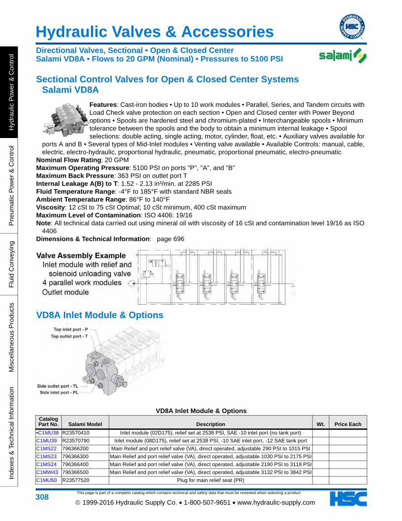
This page is part of a complete catalog which contains technical and safety data that must be reviewed when selecting a product
Hydraulic Valves & Accessories
Hyd
raul
ic P
ower
& C
ontr
olP
neum
atic
Pow
er &
Con
trol
Flu
id C
onve
ying
Mis
cella
neou
s P
rodu
cts
Inde
xes
& T
echn
ical
Info
rmat
ion
308 1999-2016 Hydraulic Supply Co. • 1-800-507-9651 • www.hydraulic-supply.com
Sectional Control Valves for Open & Closed Center Systems Salami VD8A
Features: Cast-iron bodies • Up to 10 work modules • Parallel, Series, and Tandem circuits with Load Check valve protection on each section • Open and Closed center with Power Beyond options • Spools are hardened steel and chromium-plated • Interchangeable spools • Minimum tolerance between the spools and the body to obtain a minimum internal leakage • Spool selections: double acting, single acting, motor, cylinder, float, etc. • Auxiliary valves available for
ports A and B • Several types of Mid-Inlet modules • Venting valve available • Available Controls: manual, cable, electric, electro-hydraulic, proportional hydraulic, pneumatic, proportional pneumatic, electro-pneumatic
Nominal Flow Rating: 20 GPMMaximum Operating Pressure: 5100 PSI on ports "P", "A", and "B"Maximum Back Pressure: 363 PSI on outlet port TInternal Leakage A(B) to T: 1.52 - 2.13 in³/min. at 2285 PSIFluid Temperature Range: -4°F to 185°F with standard NBR sealsAmbient Temperature Range: 86°F to 140°FViscosity: 12 cSt to 75 cSt Optimal; 10 cSt minimum, 400 cSt maximumMaximum Level of Contamination: ISO 4406: 19/16Note: All technical data carried out using mineral oil with viscosity of 16 cSt and contamination level 19/16 as ISO
4406Dimensions & Technical Information: page 696
VD8A Inlet Module & Options
VD8A Inlet Module & OptionsCatalog Part No. Salami Model Description Wt. Price Each
•C1MU38 R23570410 Inlet module (02D175), relief set at 2538 PSI, SAE -10 inlet port (no tank port)
C1MU39 R23570790 Inlet module (08D175), relief set at 2538 PSI, -10 SAE inlet port, -12 SAE tank port
C1MS22 796366200 Main Relief and port relief valve (VA), direct operated, adjustable 290 PSI to 1015 PSI
C1MS23 796366300 Main Relief and port relief valve (VA), direct operated, adjustable 1030 PSI to 2175 PSI
C1MS24 796366400 Main Relief and port relief valve (VA), direct operated, adjustable 2190 PSI to 3118 PSI
C1MW43 796366500 Main Relief and port relief valve (VA), direct operated, adjustable 3132 PSI to 3842 PSI
C1MU50 R23577520 Plug for main relief seat (PR)
Directional Valves, Sectional • Open & Closed CenterSalami VD8A • Flows to 20 GPM (Nominal) • Pressures to 5100 PSI

This page is part of a complete catalog which contains technical and safety data that must be reviewed when selecting a product
Hydraulic Valves & Accessories
Hydraulic P
ower &
Control
Pneum
atic Pow
er & C
ontrolF
luid Conveying
Miscellaneous P
roductsIndexes &
Technical Information
309 1999-2016 Hydraulic Supply Co. • 1-800-507-9651 • www.hydraulic-supply.com
VD8A Working Sections and Options
VD8A Working Sections and OptionsCatalog Part No. Salami Model Key Description Wt.
Price Each
C1MV27 S23582140 (1)
Dual working section (VD8A-2 X P01A-PRA.PRB.NPA-C2/SAE). Two parallel circuit, 4-way, 3-position, A&B closed in neutral, complete with spring centering positioner, standard protected lever control, SAE -10 work ports. Does NOT include M8 thread
lever.
C1MV30 S23582720 (1)Working section (/P01A-PRA.PRB-LTA-E1B/S), parallel circuit, 4-way, 3-position, A&B closed in neutral, complete with spring centering positioner, emergency lever control
on B side, 12VDC solenoid on A side, SAE -10 work ports.
C1MV26 S23580290 (1)Working section (/P01A-PRA.PRB-NPA-C2), parallel circuit, 4-way, 3-position, A&B
closed in neutral, complete with spring centering positioner, standard protected lever control, SAE -10 work ports. Does NOT include M8 thread lever.
C1MV31 S23582810 (1)Working section (/P02A-PRA.PRB-LTA-E1B/S), parallel circuit, 4-way, 3-position, A&B to tank in neutral, complete with spring centering positioner, emergency lever control
on B side, 12VDC solenoid on A side, SAE -10 work ports.
•C1MV32 S23582951 (1)Working section (/P02A-PRA.PRB-NPA-C2/S), parallel circuit, 4-way, 3-position, A&B to tank in neutral, complete with spring centering positioner, standard protected lever,
SAE -10 work ports.
C1MV29 S23582600 (1)Working section (/P12A-PRA.PRB-NPA-F5), parallel circuit, 4-way, 4-position, A&B closed in neutral, float in 4th position (spool out), standard protected lever control,
SAE -10 work ports. Does NOT include M8 thread lever.
C1MV28 S23582390 (1)Working section (/S01A-PRA.PRB-SLA-C2), series circuit, 4-way, 3-position, A&B
closed in neutral, complete with spring centering positioner without lever box, SAE -10 work ports. Does NOT include M8 thread lever.
C1MV33 S23583570 (1)Working section (/T01A-PRA.PRB-NPA-C2), tandem circuit, 4-way, 3-position, A&B
closed in neutral, complete with spring centering positioner, standard protected lever control, SAE -10 work ports. Does NOT include M8 thread lever.
C1MS25 796366700 (5) Port relief and anti-cavitation valve (AR), adjustable 0 PSI to 6090 PSI
C1MU50 R23577520 (5) Plug for Port Relief Seat (PR) for sections pre-arranged for auxiliary valves.
C1MS22 796366200 (5) Main Relief and port relief valve (VA), direct operated, adjustable 290 PSI to 1015 PSI
C1MS23 796366300 (5) Main Relief and port relief valve (VA), direct operated, adjustable 1030 PSI to 2175 PSI
C1MS24 796366400 (5) Main Relief and port relief valve (VA), direct operated, adjustable 2190 PSI to 3118 PSI
C1MW43 796366500 (5) Main Relief and port relief valve (VA), direct operated, adjustable 3132 PSI to 3842 PSI
C1MU49 R23577511 (5) Anticavitation valve (VR) for sections pre-arranged for auxiliary valves.
C1MU41 R23573048 A Electric kit push-pull 12 VDC with safety lever override (VD8 01A ESA), includes spool.
C1MU42 R23573049 A Electric kit push-pull 12 VDC with safety lever override (VD8 02A ESA), includes spool.
C1MU43 R23575322 A Hydraulic Proportional Control Kit, mounts on "A" and "B" side of work section.
C1MU63 R23587570 A Cross Lever for 2 Spools (L1) fulcrum on up-stream spool
C1MU64 R23587580 A Cross Lever for 2 Spools (L2) fulcrum on up-stream spool
Directional Valves, Sectional • Open & Closed CenterSalami VD8A • Flows to 20 GPM (Nominal) • Pressures to 5100 PSI

This page is part of a complete catalog which contains technical and safety data that must be reviewed when selecting a product
Hydraulic Valves & Accessories
Hyd
raul
ic P
ower
& C
ontr
olP
neum
atic
Pow
er &
Con
trol
Flu
id C
onve
ying
Mis
cella
neou
s P
rodu
cts
Inde
xes
& T
echn
ical
Info
rmat
ion
310 1999-2016 Hydraulic Supply Co. • 1-800-507-9651 • www.hydraulic-supply.com
C1MT44 R20287910 A Standard Protected Lever (NP), lever handle NOT included.
•C1MQ95 420290180 A Lever Handle with knob, M8x180
C1MU44 R23575370 A Pneumatic proportional kit (PP)
C1MU65 R23587640 A Spool seal retainer (SL)
C1MU90 R360T0200 A Cable control attachment kit (TC)
C1MU48 R23576400 B Detent Position Kit (C0), detent on each intermediate position.
C1MU46 R23576140 B Spool Positioning for Micro Switch (CE) for spool 01
C1MT45 R20288881 B Spool positioning with microswitch, conversion from (CE) to (CM), IP65.
C1MT43 R20276730 B Spool positioning with microswitch, conversion from (CE) to (CW), IP67 waterproof.
C1MU35 R23500300 B Detent Positioning Kit (R2), Detent on position 1 & 2 with spring return in neutral.
C1MU36 R23500400 B Dentent Positioning Kit (R4), Detent on position 1 with spring return in neutral.
C1MU37 R23500500 B Detent Positioning Kit (R5), Detent on position 2 with spring return in neutral.
•C1MU45 R23575490 B Detent Positioning Kit (R9), Detent on positions 1, 2, and neutral.
•C1MQ75 323511302 Spool Double Acting Motor Spool (02), A & B to tank in neutral.
•C1MQ76 323511305 Spool Single Acting Spool, "A" Working Port (05) 24.00
C1MQ77 323511306 Spool Single Acting Spool, "B" Working Port (06) 0.50
C1MQ78 323511311 Spool Double Acting Spool with Float function in 4th position (spool in) (11)
C1MU47 R23576301 SpoolDouble Acting Spool kit with Float function in 4th position (spool out) (12A-NP-F5),
includes standard protected lever and spring centered from offset positions, detent in float position
C1MQ79 323511390 Spool Double Acting Spool for Hydraulic Proportional Control (01) 1.50
C1MQ80 323511391 Spool Double Acting Motor Spool for Hydraulic Proportional Control (02)Note: Handle is not included with lever controls.
VD8A Outlet Section and Options
VD8A Outlet Section and OptionsCatalog Part No. Salami Model Description Wt. Price Each
•C1MU52 R23580030 Outlet section (U4S), -12 SAE side and top outlet ports, side port plugged.
C1MU51 R23580020 Power Beyond Sleeve Kit (Pressure Carry Over)
VD8A Working Sections and OptionsCatalog Part No. Salami Model Key Description Wt.
Price Each
Directional Valves, Sectional • Open & Closed CenterSalami VD8A • Flows to 20 GPM (Nominal) • Pressures to 5100 PSI

This page is part of a complete catalog which contains technical and safety data that must be reviewed when selecting a product
Hydraulic Valves & Accessories
Hydraulic P
ower &
Control
Pneum
atic Pow
er & C
ontrolF
luid Conveying
Miscellaneous P
roductsIndexes &
Technical Information
311 1999-2016 Hydraulic Supply Co. • 1-800-507-9651 • www.hydraulic-supply.com
VD8A Assembly Kits
VD8A Assembly KitsCatalog Part No. Salami Model Description Wt. Price Each
•C1MU53 R23585010 Assembling Kit for 1-section assembly
•C1MU54 R23585020 Assembling Kit for 2-section assembly
C1MU55 R23585030 Assembling Kit for 3-section assembly
C1MU56 R23585040 Assembling Kit for 4-section assembly
C1MU57 R23585050 Assembling Kit for 5-section assembly
C1MU58 R23585060 Assembling Kit for 6-section assembly
C1MU59 R23585070 Assembling Kit for 7-section assembly
C1MU60 R23585080 Assembling Kit for 8-section assembly
C1MU61 R23585090 Assembling Kit for 9-section assembly
C1MU62 R23585100 Assembling Kit for 10-section assembly
C1MU40 R23572500 Side Seal Kit
C1MT42 R20272590 Spool Seal Kit
Directional Valves, Sectional • Open & Closed CenterSalami VD8A • Flows to 20 GPM (Nominal) • Pressures to 5100 PSI

This page is part of a complete catalog which contains technical and safety data that must be reviewed when selecting a product
Hydraulic Valves & Accessories
Hyd
raul
ic P
ower
& C
ontr
olP
neum
atic
Pow
er &
Con
trol
Flu
id C
onve
ying
Mis
cella
neou
s P
rodu
cts
Inde
xes
& T
echn
ical
Info
rmat
ion
312 1999-2016 Hydraulic Supply Co. • 1-800-507-9651 • www.hydraulic-supply.com
Sectional Control Valves for Open & Closed Center Systems Husco Model 5000
Features: 3000 psi operating pressure rating • Open-center or closed-center operation • Hard chrome plated spools • Load check in each section • Single “low pressure” O-ring sealing between sections • Precision spool with metering notches.Options: High pressure carryover (Power Beyond) • Lock-out spool section (Built-in pilot operated check valve section) • Mid-inlet flow combiner or separator • Left-hand spool sections •
Parallel, Conventional and Series circuitry • End mechanisms: Spring centered, Detent, 4th position float, Hydraulic remote, Pneumatic remote, Automatic kick-out • Auxiliary valves: Pilot-operated, anti-cavitation check combination relief cartridges, Anti-cavitation cartridges • Regenerative spools • Specialized spools.
Maximum Operating Pressure: 3000 PSI.Maximum Outlet Port/Tank Core Pressure: 500 PSI.Seals: Buna-N standard, Viton® optional.Parallel Circuits: In a Parallel Circuit valve assembly, two or more spools may be actuated at the same time and
the oil will follow the path of least resistance. If the loads are different and the spools are fully shifted, the lightest load will operate first. If the spools are not fully shifted and the oil is metered, it is possible to direct partial flow to both loads.
Power Beyond & Closed Center Options: Valve assemblies can be made Power Beyond or Closed Center by selecting and configuring the appropriate Outlet Cover.
Dimensions & Technical Information: page 670
Directional Valves, Sectional • Open & Closed CenterHusco Model 5000 • Flows to 20 GPM (Nominal) • Pressures to 3000 PSI

This page is part of a complete catalog which contains technical and safety data that must be reviewed when selecting a product
Hydraulic Valves & Accessories
Hydraulic P
ower &
Control
Pneum
atic Pow
er & C
ontrolF
luid Conveying
Miscellaneous P
roductsIndexes &
Technical Information
313 1999-2016 Hydraulic Supply Co. • 1-800-507-9651 • www.hydraulic-supply.com
Husco Model 5000 Sectional Valve Components
Husco Model 5000 Sectional Valve ComponentsCatalog Part No. Husco Model Key Description Wt.
Price Each
C1JP46 N5002-A1 (3) Spool Section (Std Parallel Circuit), Cylinder Spool, 4-way 3-position spring-centered, SAE-8 Work Ports, without Auxiliary Valve Ports. Requires 1ea Item (6) 5.10
C1JP56 N52250-1 (6) Lever Kit, Fixed Position, Vertical 0.83
(1) Inlet & Inlet/Outlet Cover: One is required. (2) Main Relief Option: One is required if Inlet/Outlet Cover is used. (3) Spool Section: One or more is required. (4) Work Port Option: Two are required for each Spool Section that has Auxiliary Valve Porting. (5) End Mechanism Option: Optional. (6) Lever Kit: One is required for each manually operated spool section. (7) Outlet Cover: One is required. (8) Outlet Cover Option: A Shut-Off Plug is required for power beyond or closed center capability when Universal Outlet Cover is used. (9) Tie Rod Kit: One is required. The Inlet & Outlet covers are NOT included in counting the number of sections for a tie rod kit. Final torque
the two 1/2" nuts to 14 ft-lb; Final torque the 9/16" nut to 33 ft-lb.
Directional Valves, Sectional • Open & Closed CenterHusco Model 5000 • Flows to 20 GPM (Nominal) • Pressures to 3000 PSI

This page is part of a complete catalog which contains technical and safety data that must be reviewed when selecting a product
Hydraulic Valves & Accessories
Hyd
raul
ic P
ower
& C
ontr
olP
neum
atic
Pow
er &
Con
trol
Flu
id C
onve
ying
Mis
cella
neou
s P
rodu
cts
Inde
xes
& T
echn
ical
Info
rmat
ion
314 1999-2016 Hydraulic Supply Co. • 1-800-507-9651 • www.hydraulic-supply.com
Sectional Control Valves for Open & Closed Center Systems Walvoil SD8 Series
Features: Simple, compact and heavy duty designed sectional valve from 1 to 12 sections, for open and closed center hydraulic systems • Main pressure relief valve • Load check valve on every work section • Available with parallel, tandem or series circuit • Optional power beyond port • Available with manual, pneumatic, hydraulic, electro-hydraulic, solenoid or cable controls • Interchangeable spools.Nominal Flow Rating: 21 GPM.Maximum Operating Pressure: 4600 PSI.Maximum Back Pressure: 360 PSI on outlet port T.Internal Leakage A(B) to T: 0.18 in³/min at 1450 PSI differential pressure.Fluid Temperature Range: -4°F to 176°F with standard Buna-N seals.Ambient Temperature Range: -40°F to 140°F.
Viscosity: 80 to 400 SSU Operating, 70 SSU Minimum, 1950 SSU Maximum.Maximum Level of Contamination: ISO 4406 19/16.Note: Performance data measured with mineral oil of 215 SSU viscosity at 104°F.Dimensions & Technical Information: page 686
SD8 Inlet Covers & Options
SD8 Inlet Covers & OptionsCatalog Part No. Walvoil Model Key Description & (Walvoil Type Code) Wt.
Price Each
•C1HV16 613205001 (1)Inlet cover (FE-SD8/AC(YG3)-SAE) with direct pressure relief (3) 900-2900 PSI range and standard setting 1750 PSI, with blanking plug (4). SAE-10 end inlet port P and plugged SAE-10 top inlet.
4.93
•C1HT16 3XCAR110213 (3) Direct pressure relief (Type YG3-175), 1800-3600 PSI range, standard setting 2500 PSI. 0.63
Directional Valves, Sectional • Open & Closed CenterWalvoil SD8 Series • Flows to 21 GPM (Nominal) • Pressures to 4600 PSI

This page is part of a complete catalog which contains technical and safety data that must be reviewed when selecting a product
Hydraulic Valves & Accessories
Hydraulic P
ower &
Control
Pneum
atic Pow
er & C
ontrolF
luid Conveying
Miscellaneous P
roductsIndexes &
Technical Information
315 1999-2016 Hydraulic Supply Co. • 1-800-507-9651 • www.hydraulic-supply.com
SD8 Working Sections & Options
SD8 Working Sections & OptionsCatalog Part No. Walvoil Model Key Description & (Walvoil Type Code) Wt.
Price Each
•C1HV13 613105001 (1)Working section (EL-SD8/P-18L-SAE), parallel circuit, 4way 3pos A&B closed in neutral, complete with spring centering positioner (3), standard lever box (4) and blanking plugs (5). SAE-8 work ports. Does NOT include M10 thread handlever.
7.01
•C1HV14 613105301 (1)Working section (EL-SD8/P-28L-SAE), parallel circuit, 4way 3-pos A & B open to tank in neutral, complete with spring centering positioner (3), standard lever box (4) and blanking plugs (5). SAE-8 work ports. Does NOT include M10 thread handlever.
6.97
•C1HU84 5V11108000 (3) "A" side spool positioner (Type 11), with detent in positions 1, neutral and 2 0.50
•C1HQ47 170012020 (II) Handlever (Type AL01/M10x200), for standard leverbox, M10 thread x 200mm long, with black knob 0.28
•C1HQ59 170013025 (II) Handlever (Type AL01/M12x250), for mechanical joystick, M12 thread x 250mm long, with black knob 0.50
Directional Valves, Sectional • Open & Closed CenterWalvoil SD8 Series • Flows to 21 GPM (Nominal) • Pressures to 4600 PSI

This page is part of a complete catalog which contains technical and safety data that must be reviewed when selecting a product
Hydraulic Valves & Accessories
Hyd
raul
ic P
ower
& C
ontr
olP
neum
atic
Pow
er &
Con
trol
Flu
id C
onve
ying
Mis
cella
neou
s P
rodu
cts
Inde
xes
& T
echn
ical
Info
rmat
ion
316 1999-2016 Hydraulic Supply Co. • 1-800-507-9651 • www.hydraulic-supply.com
SD8 Electro-Hydraulic Feeder Kits & Options
SD8 Electro-Hydraulic Feeder Kits & OptionsCatalog Part No. Walvoil Model Key Description & (Walvoil Type Code) Wt.
Price Each
•C1HT29 4TAP318010 (3) M18 x 1.5 plug for power beyond / closed center option 0.03
SD8 Outlet Cover & Options
SD8 Outlet Cover & OptionsCatalog Part No. Walvoil Model Key Description & (Walvoil Type Code) Wt.
Price Each
•C1HV17 613305001 (1) Outlet cover (FS-SD8/RC-SAE), SAE-10 end outlet port T, plugged SAE-10 top outlet, machined for optional power beyond/closed center conversion 3.85
•C1HT29 4TAP318010 (3) M18 x 1.5 plug for power beyond / closed center option 0.03
Directional Valves, Sectional • Open & Closed CenterWalvoil SD8 Series • Flows to 21 GPM (Nominal) • Pressures to 4600 PSI

This page is part of a complete catalog which contains technical and safety data that must be reviewed when selecting a product
Hydraulic Valves & Accessories
Hydraulic P
ower &
Control
Pneum
atic Pow
er & C
ontrolF
luid Conveying
Miscellaneous P
roductsIndexes &
Technical Information
317 1999-2016 Hydraulic Supply Co. • 1-800-507-9651 • www.hydraulic-supply.com
SD8 Tie Rod & Mounting Bracket Kits
SD8 Tie Rod & Mounting Bracket KitsCatalog Part No. Walvoil Model Key Description & (Walvoil Type Code) Wt.
Price Each
•C1HU16 5TIR108128 (1) Tie rod kit for a 1-section valve assembly 0.53
•C1HU18 5TIR108169 (1) Tie rod kit for a 2-section valve assembly 0.66
•C1HU21 5TIR108210 (1) Tie rod kit for a 3-section valve assembly 0.82
•C1HU24 5TIR108251 (1) Tie rod kit for a 4-section valve assembly 0.96
•C1HU27 5TIR108292 (1) Tie rod kit for a 5-section valve assembly 1.12
•C1HU11 5STA125190 (2) Brackets kit 0.76
Directional Valves, Sectional • Open & Closed CenterWalvoil SD8 Series • Flows to 21 GPM (Nominal) • Pressures to 4600 PSI

This page is part of a complete catalog which contains technical and safety data that must be reviewed when selecting a product
Hydraulic Valves & Accessories
Hyd
raul
ic P
ower
& C
ontr
olP
neum
atic
Pow
er &
Con
trol
Flu
id C
onve
ying
Mis
cella
neou
s P
rodu
cts
Inde
xes
& T
echn
ical
Info
rmat
ion
318 1999-2016 Hydraulic Supply Co. • 1-800-507-9651 • www.hydraulic-supply.com
Sectional Control Valves for Open & Closed Center Systems Walvoil SDS150 Series
Features: Simple, compact and heavy duty designed sectional valve from 1 to 12 sections, for open and closed center hydraulic systems • Main pressure relief valve • Load check valve on every work section • Available with parallel, tandem or series circuit • Optional power beyond port • Available with manual, pneumatic, hydraulic, electro-hydraulic or cable controls • Interchangeable spools.Nominal Flow Rating: 24 GPM.Maximum Operating Pressure: 4600 PSI (Parallel or Tandem circuit). 3050 PSI (Series
circuit).Maximum Back Pressure: 360 PSI on outlet port T.Internal Leakage A(B) to T: 0.18 in³/min at 1450 PSI differential pressure.Fluid Temperature Range: -4°F to 176°F with standard Buna-N seals.Ambient Temperature Range: -40°F to 140°F.Viscosity: 80 to 400 SSU Operating, 70 SSU Minimum, 1950 SSU Maximum.Maximum Level of Contamination: ISO 4406 19/16.Note: Performance data measured with mineral oil of 215 SSU viscosity at 104°F.Dimensions & Technical Information: page 690
SDS150 Inlet Covers & Options
SDS150 Inlet Covers & OptionsCatalog Part No. Walvoil Model Key Description & (Walvoil Type Code) Wt.
Price Each
C1HV21 614266002 (1)Inlet cover (FE-SDS150/AC(YG3)-SAE) with direct pressure relief (3): 1800-2900 PSI range and standard setting 1750 PSI, with blanking plug (4). SAE-12 end inlet port P and plugged SAE-12 top inlet.
7.27
•C1HT16 3XCAR110213 (3) Direct pressure relief (Type YG3-175), 1800-3600 PSI range, standard setting 2500 PSI. 0.63
Directional Valves, Sectional • Open & Closed CenterWalvoil SDS150 Series • Flows to 24 GPM (Nominal) • Pressures to 4600 PSI

This page is part of a complete catalog which contains technical and safety data that must be reviewed when selecting a product
Hydraulic Valves & Accessories
Hydraulic P
ower &
Control
Pneum
atic Pow
er & C
ontrolF
luid Conveying
Miscellaneous P
roductsIndexes &
Technical Information
319 1999-2016 Hydraulic Supply Co. • 1-800-507-9651 • www.hydraulic-supply.com
SDS150 Working Sections & Options
SDS150 Working Sections & OptionsCatalog Part No. Walvoil Model Key Description & (Walvoil Type Code) Wt.
Price Each
C1HV19 614166001 (1)Working section (EL-SDS150/P-18L-SAE), parallel circuit, 4way 3-pos A&B closed in neutral, complete with spring centering positioner (3), standard lever box (4) and blanking plugs (5). SAE-10 work ports. Does NOT include M10 thread handlever.
10.05
C1HV20 614166302 (1)Working section (EL-SDS150/P-28L-SAE), parallel circuit, 4way 3-pos A&B open to tank in neutral, complete with spring centering positioner (3), standard lever box (4) and blanking plugs (5). SAE-10 work ports. Does NOT include M10 thread handlever.
10.02
•C1HU85 5V11110000 (3) "A" side spool positioner (11) 3-position detent kit 0.56
•C1JC50 5V08110701 (3) "A" side spool positioner (Type 8P), On/Off pneumatic, NPT 1.41
•C1HQ47 170012020 (II) Handlever (Type AL01/M10x200), for standard leverbox, M10 thread x 200mm long, with black knob 0.28
•C1HQ59 170013025 (II) Handlever (Type AL01/M12x250), for mechanical joystick, M12 thread x 250mm long, with black knob 0.50
Directional Valves, Sectional • Open & Closed CenterWalvoil SDS150 Series • Flows to 24 GPM (Nominal) • Pressures to 4600 PSI

This page is part of a complete catalog which contains technical and safety data that must be reviewed when selecting a product
Hydraulic Valves & Accessories
Hyd
raul
ic P
ower
& C
ontr
olP
neum
atic
Pow
er &
Con
trol
Flu
id C
onve
ying
Mis
cella
neou
s P
rodu
cts
Inde
xes
& T
echn
ical
Info
rmat
ion
320 1999-2016 Hydraulic Supply Co. • 1-800-507-9651 • www.hydraulic-supply.com
SDS150 Electro-Hydraulic Feeder Kits & Options
SDS150 Electro-Hydraulic Feeder Kits & OptionsCatalog Part No. Walvoil Model Key Description & (Walvoil Type Code) Wt.
Price Each
•C1HT29 4TAP318010 (3) M18 x 1.5 plug for power beyond / closed center option 0.03
SDS150 Outlet Cover & Options
SDS150 Outlet Cover & OptionsCatalog Part No. Walvoil Model Key Description & (Walvoil Type Code) Wt.
Price Each
C1HV22 614366002 (1) Outlet cover (Type FS-SDS150/RC-SAE), SAE-12 end outlet port T, plugged SAE-12 top outlet, machined for optional power beyond/closed center conversion 4.12
•C1HT29 4TAP318010 (3) M18 x 1.5 plug for power beyond / closed center option 0.03
Directional Valves, Sectional • Open & Closed CenterWalvoil SDS150 Series • Flows to 24 GPM (Nominal) • Pressures to 4600 PSI

This page is part of a complete catalog which contains technical and safety data that must be reviewed when selecting a product
Hydraulic Valves & Accessories
Hydraulic P
ower &
Control
Pneum
atic Pow
er & C
ontrolF
luid Conveying
Miscellaneous P
roductsIndexes &
Technical Information
321 1999-2016 Hydraulic Supply Co. • 1-800-507-9651 • www.hydraulic-supply.com
SDS150 Tie Rod & Mounting Bracket Kits
SDS150 Tie Rod & Mounting Bracket KitsCatalog Part No. Walvoil Model Key Description & (Walvoil Type Code) Wt.
Price Each
C1HU38 5TIR110149 (1) Tie rod kit for a 1-section valve assembly 0.23
C1HU41 5TIR110194 (1) Tie rod kit for a 2-section valve assembly 1.34
C1HU44 5TIR110239 (1) Tie rod kit for a 3-section valve assembly 1.57
C1HU54 5TIR110374 (1) Tie rod kit for a 6-section valve assembly 2.33
•C1HU11 5STA125190 (2) Brackets kit 0.76
Directional Valves, Sectional • Open & Closed CenterWalvoil SDS150 Series • Flows to 24 GPM (Nominal) • Pressures to 4600 PSI

This page is part of a complete catalog which contains technical and safety data that must be reviewed when selecting a product
Hydraulic Valves & Accessories
Hyd
raul
ic P
ower
& C
ontr
olP
neum
atic
Pow
er &
Con
trol
Flu
id C
onve
ying
Mis
cella
neou
s P
rodu
cts
Inde
xes
& T
echn
ical
Info
rmat
ion
322 1999-2016 Hydraulic Supply Co. • 1-800-507-9651 • www.hydraulic-supply.com
Sectional Control Valves for Open & Closed Center Systems Salami VDP08
Features: Load sensing directional control valve VDP08 offers a load-independent flow control (flow in each section depends only on the spool position and not on the load acting on any function), good metering curves and chance of energy saving. The spool acts as a variable throttling on which the pressure drop is maintained constant, so that each spool position arouses a determinate flow rate.There is a closed center version for variable displacement pumps and open center version for fixed displacement pumps. The valve, through the LS signal, sets the pump displacement required by the actuator plus a little leakage compensation flow, the pump always works almost at minimum power possible,
with clear advantages in terms of energy saving. When several spools are actuated, only the highest of the corresponding LS signals reaches the pump; in the remaining sections the compensators keep the pressure drop on the spool constant, maintaining the flow rate equal to that required by the actuator and independent of the pump pressure. When all the spools are in neutral position (pump stand-by), the pump requires a very little flow (leakage compensation) at the stand-by pressure (14 bar - 200 psi). Open center version for fixed displacement pumps, the flow regulator in the inlet module, controlled by the LS signal, drains to tank all the flow exceeding the value required by the actuators, generating in the valve the same working conditions as of a variable displacement pump. The advantages due to flow regulation hold, whereas energy saving is reduced.Salami directional control valves are modular construction and
consist of an inlet/outlet section, up to 8 working sections and an end plate. All these elements are secured in one block by
means of tie-rods.Salami directional control valves have the following features: Special cast-iron body; Spool construction in steel, hardened and chromium-plated to obtain a higher surface hardness, a better corrosion resistance,
and wearing reduction; Minimum tolerance between spools and body to obtain a minimum internal leakage; Interchangeability of all spools; Possibility of auxiliary valves on port A and B; Several spool controls.
Nominal Flow Rating: 25 GPMMaximum Operating Pressure: 4560 PSI on ports "P"; 5000 PSI on ports "A", and "B"Maximum Back Pressure: 145 PSI on outlet port "T"Internal Leakage A(B) to T: 1.8 - 2.1 in³/min. at 2285 PSIFluid Temperature Range: -4°F to 185°F with standard NBR sealsAmbient Temperature Range: 86°F to 140°FViscosity: 12 cSt to 75 cSt Optimal; 10 cSt minimum, 460 cSt maximumMaximum Level of Contamination: ISO 4406: 19/16Note: All technical data carried out using mineral oil with viscosity of 16 cSt and contamination level 19/16 as ISO
4406Dimensions & Technical Information: page 699
VDP08 Inlet Modules & Options
Directional Valves, Sectional • Open & Closed CenterSalami VDP08 • Flows to 25 GPM (Nominal) • Pressures to 4560 PSI

This page is part of a complete catalog which contains technical and safety data that must be reviewed when selecting a product
Hydraulic Valves & Accessories
Hydraulic P
ower &
Control
Pneum
atic Pow
er & C
ontrolF
luid Conveying
Miscellaneous P
roductsIndexes &
Technical Information
323 1999-2016 Hydraulic Supply Co. • 1-800-507-9651 • www.hydraulic-supply.com
VDP08 Inlet Modules & OptionsCatalog Part No. Salami Model Description & (Salami Commercial Codes) Wt. Price Each
C1MW57 R24178020 Inlet module open center (VDP08F*) configured for fixed displacement pump
C1MW56 R24178040 Inlet module closed center (VDP08V*) configured for variable displacement pump
C1MU69 R24170130 Inlet module kit (F) parts to convert for fixed displacment pump
C1MU68 R24170120 Inlet module kit (V) parts to convert for variable displacment pump
VDP08 Working Modules and Options
VDP08 Working Modules and OptionsCatalog Part No. Salami Model Description & (Salami Commercial Codes) Wt. Price Each
C1MW55 S24180070 Work module, 2.2 GPM pressure compensated, manual control (NL), double acting cylinder spool, work port valves plugged (PRA.PRB), SAE -10 ports.
C1MW53 S24180083Work module, 4.2 GPM pressure compensated, hydraulic proportional control (IP) +
manual control (NL), double acting cylinder spool, work port valves plugged (PRA.PRB), SAE -10 ports.
C1MW54 S24180080 Work module, 4.2 GPM pressure compensated, manual control (NL), double acting cylinder spool, work port valves plugged (PRA.PRB), SAE -10 ports.
C1MW45 S24180770Work module, 4.2 GPM pressure compensated, manual control (NL), double acting
cylinder spool, work port valves plugged (PRA.PRB), load sense valve ports plugged (PRLSA.PRLSB), SAE -10 ports.
C1MW52 S24180090 Work module, 6.6 GPM pressure compensated, manual control (NL), double acting cylinder spool, work port valves plugged (PRA.PRB), SAE -10 ports.
C1MW50 S24180103Work module, 11.8 GPM pressure compensated, hydraulic proportional control (IP) +
manual control (NL), double acting cylinder spool, work port valves plugged (PRA.PRB), SAE -10 ports.
C1MW51 S24180100 Work module, 11.8 GPM pressure compensated, manual control (NL), double acting cylinder spool, work port valves plugged (PRA.PRB), SAE -10 ports.
C1MW49 S24180110 Work module, 16.6 GPM pressure compensated, manual control (NL), double acting cylinder spool, work port valves plugged (PRA.PRB), SAE -10 ports.
C1MW47 S24180645Work module, 25 GPM pressure compensated, electro-proportional control 12VDC +
manual control (NL), double acting cylinder spool, work port valves plugged (PRA.PRB), load sense valve ports plugged (PRLSA.PRLSB), SAE -10 ports.
C1MW48 S24180120 Work module, 25 GPM pressure compensated, manual control (NL), double acting cylinder spool, work port valves plugged (PRA.PRB), SAE -10 ports.
C1MW46 S24180681Work module, 25 GPM pressure compensated, pneumatic proportional control (PP) +
manual control (NL), double acting cylinder spool, work port valves plugged (PRA.PRB), SAE -10 ports.
C1MR84 794129301 Port relief valve, non-adjustable, 362 PSI
C1MR85 794129302 Port relief valve, non-adjustable, 464 PSI
C1MR86 794129303 Port relief valve, non-adjustable, 580 PSI
C1MR87 794129304 Port relief valve, non-adjustable, 725 PSI
C1MR88 794129305 Port relief valve, non-adjustable, 910 PSI
C1MR89 794129306 Port relief valve, non-adjustable, 1160 PSI
Directional Valves, Sectional • Open & Closed CenterSalami VDP08 • Flows to 25 GPM (Nominal) • Pressures to 4560 PSI

This page is part of a complete catalog which contains technical and safety data that must be reviewed when selecting a product
Hydraulic Valves & Accessories
Hyd
raul
ic P
ower
& C
ontr
olP
neum
atic
Pow
er &
Con
trol
Flu
id C
onve
ying
Mis
cella
neou
s P
rodu
cts
Inde
xes
& T
echn
ical
Info
rmat
ion
324 1999-2016 Hydraulic Supply Co. • 1-800-507-9651 • www.hydraulic-supply.com
C1MR90 794129307 Port relief valve, non-adjustable, 1450 PSI
C1MR91 794129308 Port relief valve, non-adjustable, 1810 PSI
C1MR92 794129309 Port relief valve, non-adjustable, 2000 PSI
C1MR93 794129310 Port relief valve, non-adjustable, 2300 PSI
C1MR94 794129311 Port relief valve, non-adjustable, 2530 PSI
C1MR95 794129312 Port relief valve, non-adjustable, 2715 PSI
C1MR96 794129313 Port relief valve, non-adjustable, 3000 PSI
C1MR97 794129314 Port relief valve, non-adjustable, 3300 PSI
C1MR98 794129315 Port relief valve, non-adjustable, 3600 PSI
C1MR99 794129316 Port relief valve, non-adjustable, 4000 PSI
C1MS11 794129317 Port relief valve, non-adjustable, 4569 PSI
C1MS12 794129318 Port relief valve, non-adjustable, 5076 PSI
C1MU67 R24170061 Port load sense relief valve (LSVS) adjustable 435 PSI to 1595 PSI
C1MU66 R24170060 Port load sense relief valve (LSVS) adjustable 1595 PSI to 5510 PSI
C1MU71 R24172751 LS port plug for ports A and B
C1MU73 R24172780 LS port plug for single acting port A
C1MU72 R24172770 LS port plug for single acting port B
C1MU70 R24172580 Section side seal kit
VDP08 End Plates & Options
VDP08 End Plates & OptionsCatalog Part No. Salami Model Description & (Salami Commercial Codes) Wt. Price Each
C1MU81 R24190010 End Plate (U0) for work modules with manual control
C1MU82 R24190020 End Plate (U1) for work modules with electro-proportional control
VDP08 Working Modules and OptionsCatalog Part No. Salami Model Description & (Salami Commercial Codes) Wt. Price Each
Directional Valves, Sectional • Open & Closed CenterSalami VDP08 • Flows to 25 GPM (Nominal) • Pressures to 4560 PSI

This page is part of a complete catalog which contains technical and safety data that must be reviewed when selecting a product
Hydraulic Valves & Accessories
Hydraulic P
ower &
Control
Pneum
atic Pow
er & C
ontrolF
luid Conveying
Miscellaneous P
roductsIndexes &
Technical Information
325 1999-2016 Hydraulic Supply Co. • 1-800-507-9651 • www.hydraulic-supply.com
VDP08 Assembly Kits
VDP08 Assembly KitsCatalog Part No. Salami Model Description & (Salami Commercial Codes) Wt. Price Each
C1MU75 R24185010 Tie rod and nut kit for 1 section assembly with inlet and outlet
C1MU76 R24185020 Tie rod and nut kit for 2 section assembly with inlet and outlet
C1MU77 R24185030 Tie rod and nut kit for 3 section assembly with inlet and outlet
C1MU78 R24185040 Tie rod and nut kit for 4 section assembly with inlet and outlet
C1MU79 R24185050 Tie rod and nut kit for 5 section assembly with inlet and outlet
C1MU80 R24185060 Tie rod and nut kit for 6 section assembly with inlet and outlet
Directional Valves, Sectional • Open & Closed CenterSalami VDP08 • Flows to 25 GPM (Nominal) • Pressures to 4560 PSI

This page is part of a complete catalog which contains technical and safety data that must be reviewed when selecting a product
Hydraulic Valves & Accessories
Hyd
raul
ic P
ower
& C
ontr
olP
neum
atic
Pow
er &
Con
trol
Flu
id C
onve
ying
Mis
cella
neou
s P
rodu
cts
Inde
xes
& T
echn
ical
Info
rmat
ion
326 1999-2016 Hydraulic Supply Co. • 1-800-507-9651 • www.hydraulic-supply.com
Sectional Control Valves for Open & Closed Center Systems Salami VD10A
Features: Cast-iron bodies • Up to 10 work modules • Parallel, Series, and Tandem circuits with Load Check valve protection on each section • Open and Closed center with Power Beyond options • Spools are hardened steel and chromium-plated • Interchangeable spools • Minimum tolerance between the spools and the body to obtain a minimum internal leakage • Spool selections: double acting, single acting, motor, cylinder, float, etc. • Auxiliary valves available for ports A and B • Several types of Mid-Inlet modules • Venting valve available • Available Controls: manual, cable, electric, electro-hydraulic, proportional hydraulic, pneumatic, proportional pneumatic, electro-pneumatic.Nominal Flow Rating: 32 GPM
Maximum Operating Pressure: 4000 PSI on ports "P"; 4500 PSI on ports "A", and "B"Maximum Back Pressure: 363 PSI on outlet port "T"Internal Leakage A(B) to T: 2.43 - 3.34 in³/min. at 2285 PSIFluid Temperature Range: -4°F to 185°F with standard NBR sealsAmbient Temperature Range: 86°F to 140°FViscosity: 12 cSt to 75 cSt Optimal; 10 cSt minimum, 460 cSt maximumMaximum Level of Contamination: ISO 4406: 19/16Note: All technical data carried out using mineral oil with viscosity of 16 cSt and contamination level 19/16 as ISO
4406Dimensions & Technical Information: page 697
VD10A Inlet Modules & Options
VD10A Inlet Modules & OptionsCatalog Part No. Salami Model Description & (Salami Commercial Codes) Wt. Price Each
C1MV15 S22081401 Inlet module + working section (/02D175/P01A-PRA.PRB-MLA-C2/) Relief set at 2538 PSI with SAE -12 ports
C1MT46 R22070030 Main relief valve (VS) adjustable 1500 PSI to 3000 PSI
Directional Valves, Sectional • Open & Closed CenterSalami VD10A • Flows to 32 GPM (Nominal) • Pressures to 4000 PSI

This page is part of a complete catalog which contains technical and safety data that must be reviewed when selecting a product
Hydraulic Valves & Accessories
Hydraulic P
ower &
Control
Pneum
atic Pow
er & C
ontrolF
luid Conveying
Miscellaneous P
roductsIndexes &
Technical Information
327 1999-2016 Hydraulic Supply Co. • 1-800-507-9651 • www.hydraulic-supply.com
C1MT47 R22070040 Main relief valve (VS) adjustable 3000 PSI to 4600 PSI
•C1MT48 R22070140 Main relief valve plug
VD10A Working Sections and Options
VD10A Working Sections and OptionsCatalog Part No. Salami Model Description & (Salami Commercial Codes) Wt. Price Each
C1MV14 S22081391Work section (/P01A-PRA.PRB-MLA-C2/S) parallel circuit, 4-way 3-position, A & B closed in neutral, complete with spring centering positioner, not protected clamp lever control and
port valve plugs. SAE -12 work ports.
C1MW37 S22081501Work section (/P02A-PRA.PRB-MLA-C2/S) parallel circuit, 4-way 3-position, A & B open to tank in neutral, complete with spring centering positioner, not protected clamp lever control
and port valve plugs. SAE -12 work ports.
C1MW38 S22081531Work section (/P12A-PRA.PRB-MLA-F5/S) parallel circuit, 4-way 4-position, A & B closed in neutral, float position spool out, complete with spring centering positioner, not protected
clamp lever control and port valve plugs. SAE -12 work ports.
C1MW39 S22081880Work section (/S01A-PRA.PRB-MLA-C2/S) series circuit, 4-way 3-position, A & B closed in
neutral, complete with spring centering positioner, not protected clamp lever control and port valve plugs. SAE -12 work ports.
C1MT68 R22470081 Pilot operated port relief valve, 725 PSI to 4060 PSI
C1MT69 R22470082 Pilot operated port relief valve, 1450 PSI to 5800 PSI
C1MT50 R22078410 Port relief valve (VA) adjustable 725 PSI to 1525 PSI
C1MT51 R22078420 Port relief valve (VA) adjustable 1525 PSI to 3000 PSI
C1MT49 R22078390 Port relief valve (VA) adjustable 3000 PSI to 5075 PSI
C1MT52 R22078440 Port anticavitation valve (VR)
C1MT67 R22470080 Port relief and anti-cavitation check (AR) adjustable to 4568 PSI
C1MQ60 322011317 Double acting motor spool (02A-M)
C1MQ63 322011321 Double acting motor spool, "A" port blocked (04A-G)
C1MQ61 322011318 Single acting spool, "A" working port (05A-A) 1.50
C1MQ62 322011319 Single acting spool, "B" working port (06A-B)
C1MW40 322011324 Double acting cyinder spool for Hydraulic Proportional (IP) control (01A-M)
C1MQ65 322011325 Double acting motor spool for Hydraulic Proportional (IP) control (02A-M)
C1MT64 R22400309 Detent kit (R2) three position
C1MT65 R22400409 Detent kit (R4) position 1
C1MT66 R22400509 Detent kit (R5) position 2
C1MT74 R22475079 Hydraulic proportional control kit (IP)
C1MT62 R22176331 Pneumatic proportional control kit (PP)
C1MU92 R360T0500 Cable remote control actuator
C1MT63 R22187840 Joystick control for two spools (L1/L2)
C1MT70 R22472519 Spool seal kit
VD10A Inlet Modules & OptionsCatalog Part No. Salami Model Description & (Salami Commercial Codes) Wt. Price Each
Directional Valves, Sectional • Open & Closed CenterSalami VD10A • Flows to 32 GPM (Nominal) • Pressures to 4000 PSI

This page is part of a complete catalog which contains technical and safety data that must be reviewed when selecting a product
Hydraulic Valves & Accessories
Hyd
raul
ic P
ower
& C
ontr
olP
neum
atic
Pow
er &
Con
trol
Flu
id C
onve
ying
Mis
cella
neou
s P
rodu
cts
Inde
xes
& T
echn
ical
Info
rmat
ion
328 1999-2016 Hydraulic Supply Co. • 1-800-507-9651 • www.hydraulic-supply.com
VD10A Outlet Section & Options
VD10A Outlet Section & OptionsCatalog Part No. Salami Model Description & (Salami Commercial Codes) Wt. Price Each
C1MT61 R22090050 Outlet section (/U4S-SAE) with two SAE -12 ports. End port (TL) plugged and top port (T).
C1MT53 R22080130 Carry over kit, SAE -12 port
VD10A Assembly Kits
VD10A Assembly KitsCatalog Part No. Salami Model Description & (Salami Commercial Codes) Wt. Price Each
C1MW42 R22085110 Assembling kit for 1 section valve assembly
C1MT54 R22085120 Assembling kit for 2 section valve assembly
C1MT55 R22085130 Assembling kit for 3 section valve assembly
C1MT56 R22085140 Assembling kit for 4 section valve assembly
C1MT57 R22085150 Assembling kit for 5 section valve assembly
C1MT58 R22085160 Assembling kit for 6 section valve assembly
C1MT59 R22085170 Assembling kit for 7 section valve assembly
C1MT60 R22085180 Assembling kit for 8 section valve assembly
Directional Valves, Sectional • Open & Closed CenterSalami VD10A • Flows to 32 GPM (Nominal) • Pressures to 4000 PSI

This page is part of a complete catalog which contains technical and safety data that must be reviewed when selecting a product
Hydraulic Valves & Accessories
Hydraulic P
ower &
Control
Pneum
atic Pow
er & C
ontrolF
luid Conveying
Miscellaneous P
roductsIndexes &
Technical Information
329 1999-2016 Hydraulic Supply Co. • 1-800-507-9651 • www.hydraulic-supply.com
Sectional Control Valves for Open & Closed Center Systems Walvoil SD16 Series
Features: Simple, compact and heavy duty designed sectional valve from 1 to 12 sections, for open and closed center hydraulic systems • Main pressure relief valve • Load check valve on every work section • Available with parallel, tandem or series circuit • Optional power beyond port • Available with manual, pneumatic, hydraulic, electro-hydraulic or cable controls • Interchangeable spools.Nominal Flow Rating: 37 GPM.Maximum Operating Pressure: 4600 PSI (Parallel or Tandem circuit). 3050 PSI (Series circuit).Maximum Back Pressure: 360 PSI on outlet port T.
Internal Leakage A(B) to T: 0.18 in³/min at 1450 PSI differential pressure.Fluid Temperature Range: -4°F to 176°F with standard Buna-N seals.Ambient Temperature Range: -40°F to 140°F.Viscosity: 80 to 400 SSU Operating, 70 SSU Minimum, 1950 SSU Maximum.Maximum Level of Contamination: ISO 4406 19/16.Note: Performance data measured with mineral oil of 215 SSU viscosity at 104°F.Dimensions & Technical Information: page 688
SD16 Inlet Covers & Options
SD16 Inlet Covers & OptionsCatalog Part No. Walvoil Model Key Description & (Walvoil Type Code) Wt.
Price Each
C1KK62 618205004 (1)Inlet cover (FE SD16/AC(XG-120)F-SAE) with pilot-operated pressure relief (3) 360-4600 PSI range and standard setting 1750 PSI, with anit-cavitation plug (4). SAE-16 side inlet port P and plugged SAE-16 top inlet.
9.30
Directional Valves, Sectional • Open & Closed CenterWalvoil SD16 Series • Flows to 37 GPM (Nominal) • Pressures to 4600 PSI

This page is part of a complete catalog which contains technical and safety data that must be reviewed when selecting a product
Hydraulic Valves & Accessories
Hyd
raul
ic P
ower
& C
ontr
olP
neum
atic
Pow
er &
Con
trol
Flu
id C
onve
ying
Mis
cella
neou
s P
rodu
cts
Inde
xes
& T
echn
ical
Info
rmat
ion
330 1999-2016 Hydraulic Supply Co. • 1-800-507-9651 • www.hydraulic-supply.com
•C1KK61 618205001 (1)Inlet cover (FE-SD16/AD(YG3)-SAE) with direct pressure relief (3) 1800-3600 PSI range and standard setting 2500 PSI, with blanking plug (4). SAE-16 top inlet port P and plugged SAE-16 end inlet.
9.50
C1HV70 XGIU641250 (2) Inlet port option, gauge port plug, SAE-16 x 1/4-19 BSPP 0.39
SD16 Working Sections & Options
SD16 Working Sections & OptionsCatalog Part No. Walvoil Model Key Description & (Walvoil Type Code) Wt.
Price Each
•C1KK60 618105004 (1)Working section (EL-SD16/P-18L-SAE), parallel circuit, 4way 3pos A&B closed in neutral, complete with spring centering positioner (3), standard lever box (4) and blanking plugs (5). SAE-12 work ports. Does NOT include M10 thread handlever.
12.43
•C1KK59 618101006 (1)Working section (EL-SD16/P-28L-SAE), parallel circuit, 4way 3-pos A&B open to tank in neutral, complete with spring centering positioner (3), standard lever box (4) and blanking plugs (5). SAE-12 work ports. Does NOT include M10 thread handlever.
12.43
•C1JC50 5V08110701 (3) "A" side spool positioner (Type 8P), On/Off pneumatic, NPT 1.41
C1KN76 X011411100 (5) Port relief option (Type U(G3-100)), anti-shock & anti-cavitation valve, 1450-3600 PSI range, standard setting 1450 PSI 0.40
•C1HQ47 170012020 (II) Handlever (Type AL01/M10x200), for standard leverbox, M10 thread x 200mm long, with black knob 0.28
•C1HQ59 170013025 (II) Handlever (Type AL01/M12x250), for mechanical joystick, M12 thread x 250mm long, with black knob 0.50
SD16 Inlet Covers & OptionsCatalog Part No. Walvoil Model Key Description & (Walvoil Type Code) Wt.
Price Each
Directional Valves, Sectional • Open & Closed CenterWalvoil SD16 Series • Flows to 37 GPM (Nominal) • Pressures to 4600 PSI

This page is part of a complete catalog which contains technical and safety data that must be reviewed when selecting a product
Hydraulic Valves & Accessories
Hydraulic P
ower &
Control
Pneum
atic Pow
er & C
ontrolF
luid Conveying
Miscellaneous P
roductsIndexes &
Technical Information
331 1999-2016 Hydraulic Supply Co. • 1-800-507-9651 • www.hydraulic-supply.com
SD16 Outlet Cover & Options
SD16 Outlet Cover & OptionsCatalog Part No. Walvoil Model Key Description & (Walvoil Type Code) Wt.
Price Each
•C1KF76 618305003 (1) Outlet cover (FS-SD16/RC-SAE), SAE-16 end outlet port T, plugged SAE-16 top outlet, machined for optional power beyond/closed center conversion 6.52
•C1HT29 4TAP318010 (3) M18 x 1.5 plug for power beyond / closed center option 0.03
SD16 Tie Rod & Mounting Bracket Kits
SD16 Tie Rod & Mounting Bracket KitsCatalog Part No. Walvoil Model Key Description & (Walvoil Type Code) Wt.
Price Each
C1MM60 5V09110000
•C1HU39 5TIR110170 (1) Tie rod kit for a 1-section valve assembly 1.21
•C1HU43 5TIR110218 (1) Tie rod kit for a 2-section valve assembly 1.47
•C1HU46 5TIR110266 (1) Tie rod kit for a 3-section valve assembly 1.73
•C1HU49 5TIR110316 (1) Tie rod kit for a 4-section valve assembly 2.01
C1JR82 5TIR110554 (1) Tie rod kit for a 9-section valve assembly 3.32
C1HU12 5STA125220 (2) Brackets kit 1.20
Directional Valves, Sectional • Open & Closed CenterWalvoil SD16 Series • Flows to 37 GPM (Nominal) • Pressures to 4600 PSI

This page is part of a complete catalog which contains technical and safety data that must be reviewed when selecting a product
Hydraulic Valves & Accessories
Hyd
raul
ic P
ower
& C
ontr
olP
neum
atic
Pow
er &
Con
trol
Flu
id C
onve
ying
Mis
cella
neou
s P
rodu
cts
Inde
xes
& T
echn
ical
Info
rmat
ion
332 1999-2016 Hydraulic Supply Co. • 1-800-507-9651 • www.hydraulic-supply.com
Sectional Control Valves for Open & Closed Center Systems Husco Model 6000
Features: Low effort spools • Zero leak spool seals • Open center or closed center operation • Hard chrome plated spools • Load check in each section • Single low pressure o-ring sealing between sections • Precision metering.Options: High pressure carryover (Power Beyond) • Lock-out spool section (Built-in pilot operated check valve section) • Mid-inlet flow combiner or separator • Left-hand spool sections •
Parallel, Conventional and Series circuitry • End mechanisms: Spring centered, Detent, 4th position float, Hydraulic pilot operated, Automatic kick-out, Magnetic detent • Auxiliary valves: Pilot-operated, anti-cavitation check combination relief cartridges, Anti-cavitation cartridges • Regenerative spools • Specialized spools.
Maximum Operating Pressure: 3400 PSI.Maximum Outlet Port/Tank Core Pressure: 250 PSI.Seals: Buna-N standard, Viton® optional.Parallel Circuits: In a Parallel Circuit valve assembly, two or more spools may be actuated at the same time and
the oil will follow the path of least resistance. If the loads are different and the spools are fully shifted, the lightest load will operate first. If the spools are not fully shifted and the oil is metered, it is possible to direct partial flow to both loads.
Power Beyond & Closed Center Options: Valve assemblies can be made Power Beyond or Closed Center by selecting and configuring the appropriate Outlet Cover.
Dimensions & Technical Information: page 671
Directional Valves, Sectional • Open & Closed CenterHusco Model 6000 • Flows to 40 GPM (Nominal) • Pressures to 3400 PSI

This page is part of a complete catalog which contains technical and safety data that must be reviewed when selecting a product
Hydraulic Valves & Accessories
Hydraulic P
ower &
Control
Pneum
atic Pow
er & C
ontrolF
luid Conveying
Miscellaneous P
roductsIndexes &
Technical Information
333 1999-2016 Hydraulic Supply Co. • 1-800-507-9651 • www.hydraulic-supply.com
Husco Model 6000 Sectional Valve Components
Husco Model 6000 Sectional Valve ComponentsCatalog Part No. Husco Model Key Description Wt.
Price Each
C1JL48 N6105-A (6) Heavy Duty Lever Kit 2.01
(1) Inlet & Inlet/Outlet Cover: One is required. (2) Main Relief Option: One is required if Inlet/Outlet Cover is used. (3) Spool Section: One or more is required. (4) Work Port Option: Two are required for each Spool Section that has Auxiliary Valve Porting. (5) End Mechanism Option: Optional. (6) Lever Kit: One is required for each manually operated spool section. (7) Outlet Cover: One is required. (8) Outlet Cover Option: A Shut-Off Plug is required for power beyond or closed center capability when Universal Outlet Cover is used. (9) Tie Rod Kit: One is required. The Inlet & Outlet covers are NOT included in counting the number of sections for a tie rod kit. Final torque
the two 11/16" nuts to 48 ±5 ft-lb; Final torque the 3/4" nut to 74 ± 8 ft-lb.
Directional Valves, Sectional • Open & Closed CenterHusco Model 6000 • Flows to 40 GPM (Nominal) • Pressures to 3400 PSI

This page is part of a complete catalog which contains technical and safety data that must be reviewed when selecting a product
Hydraulic Valves & Accessories
Hyd
raul
ic P
ower
& C
ontr
olP
neum
atic
Pow
er &
Con
trol
Flu
id C
onve
ying
Mis
cella
neou
s P
rodu
cts
Inde
xes
& T
echn
ical
Info
rmat
ion
334 1999-2016 Hydraulic Supply Co. • 1-800-507-9651 • www.hydraulic-supply.com
Sectional Control Valves for Open & Closed Center Systems Salami VD12A
Features: Cast-iron bodies • Up to 10 work modules • Parallel, Series, and Tandem circuits with Load Check valve protection on each section • Open and Closed center with Power Beyond options • Spools are hardened steel and chromium-plated • Interchangeable spools • Minimum tolerance between the spools and the body to obtain a minimum internal leakage • Spool selections: double acting, single acting, motor, cylinder, float, etc. • Auxiliary valves available for ports A and B • Several types of Mid-Inlet modules • Venting valve available • Available Controls: manual, cable, electric, electro-hydraulic, proportional hydraulic, pneumatic, proportional pneumatic, electro-pneumatic.
Nominal Flow Rating: 48 GPMMaximum Operating Pressure: 4000 PSI on ports "P"; 4500 PSI on ports "A", and "B"Maximum Back Pressure: 363 PSI on outlet port "T"Internal Leakage A(B) to T: 2.43 - 3.34 in³/min. at 2285 PSIFluid Temperature Range: -4°F to 185°F with standard NBR sealsAmbient Temperature Range: 86°F to 140°FViscosity: 12 cSt to 75 cSt Optimal; 10 cSt minimum, 460 cSt maximumMaximum Level of Contamination: ISO 4406: 19/16Note: All technical data carried out using mineral oil with viscosity of 16 cSt and contamination level 19/16 as ISO
4406Dimensions & Technical Information: page 698
VD12A Inlet Modules & Options
VD12A Inlet Modules & OptionsCatalog Part No. Salami Model Description & (Salami Commercial Codes) Wt. Price Each
•C1MT72 R22472830 Inlet module with main relief set at 2537 PSI, SAE -16 top and side port, top port plugged (02P175/SAE)
C1MT73 R22472840 Inlet module with main relief set at 2537 PSI, SAE -20 top and side port, top port plugged (02P175/SAE)
C1MV17 S22480420Inlet module (side inlet, direct relief set at 2537 PSI) + work section (parallel section, 4-way,
3-position, spring centered, A & B blocked in neutral, port valves plugged, not protected clamp lever on A side, SAE -16 ports (02D175/P01A-PRA.PRB-MLA-C2/S)
C1MT46 R22070030 Main relief valve (VS) adjustable 1500 PSI to 3000 PSI
C1MT47 R22070040 Main relief valve (VS) adjustable 3000 PSI to 4600 PSI
•C1MT48 R22070140 Main relief valve plug
Note: Handle not included with work section lever controls.
Directional Valves, Sectional • Open & Closed CenterSalami VD12A • Flows to 48 GPM (Nominal) • Pressures to 4000 PSI

This page is part of a complete catalog which contains technical and safety data that must be reviewed when selecting a product
Hydraulic Valves & Accessories
Hydraulic P
ower &
Control
Pneum
atic Pow
er & C
ontrolF
luid Conveying
Miscellaneous P
roductsIndexes &
Technical Information
335 1999-2016 Hydraulic Supply Co. • 1-800-507-9651 • www.hydraulic-supply.com
VD12A Working Sections and Options
VD12A Working Sections and OptionsCatalog Part No. Salami Model Description & (Salami Commercial Codes) Wt. Price Each
•C1MV16 S22480410Working section, parallel circuit, 4-way, 3-position, A & B blocked in neutral, spring
centered, work port valves plugged, not protected clamp lever, SAE -16 ports (/P01A-PRA.PRB-MLA-C2/S)
C1NC53 S22480660Working section, parallel circuit, 4-way, 3-position, A & B to T in neutral spring centered,
work port valves plugged, not protected clamp lever, SAE -16 ports (/P02A-PRA.PRB-MLA-C2/S)
C1MV18 S22480470Working section, parallel circuit, 4-way, 4-position, A & B blocked in neutral spring
centered, A & B to tank in 4th position, work port valves plugged, not protected clamp lever, SAE -16 ports (/P12A-PRA.PRB-MLA-F5/S)
C1NC54 S22480670Working section, parallel circuit, 3-way, 3-position, on B work port, B blocked in neutral,
spring centered, work port valves plugged, not protected clamp lever, SAE -16 ports (/P06A-PRA.PRB-MLA-C2/S)
C1MV19 S22480500Working section, tandem circuit, 4-way, 3-position, A & B blocked in neutral, spring
centered, work port valves plugged, not protected clamp lever, SAE -16 ports (/T01A-PRA.PRB-MLA-C2/S)
C1MT68 R22470081 Pilot operated port relief valve, 725 PSI to 4060 PSI
C1MT69 R22470082 Pilot operated port relief valve, 1450 PSI to 5800 PSI
C1MT50 R22078410 Port relief valve (VA) adjustable 725 PSI to 1525 PSI
C1MT51 R22078420 Port relief valve (VA) adjustable 1525 PSI to 3000 PSI
C1MT49 R22078390 Port relief valve (VA) adjustable 3000 PSI to 5075 PSI
C1MT52 R22078440 Port anticavitation valve (VR)
C1MZ20 322411332 Spool (02A-M), double acting motor spool
C1MQ64 322011322 Spool (02A-M), double acting motor spool for "IP" control
C1MU92 R360T0500 Cable remote control actuator (TC)
C1MT62 R22176331 Pneumatic proportional control kit (PP)
C1MT64 R22400309 Detent kit (R2) three position
C1MT64 R22400409 Detent kit (R4) three position
C1MT74 R22475079 Hydraulic proportional control kit (IP)
C1MT70 R22472519 Spool seal kit
Note: Handle not included with work section lever controls.
Directional Valves, Sectional • Open & Closed CenterSalami VD12A • Flows to 48 GPM (Nominal) • Pressures to 4000 PSI
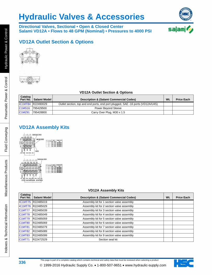
This page is part of a complete catalog which contains technical and safety data that must be reviewed when selecting a product
Hydraulic Valves & Accessories
Hyd
raul
ic P
ower
& C
ontr
olP
neum
atic
Pow
er &
Con
trol
Flu
id C
onve
ying
Mis
cella
neou
s P
rodu
cts
Inde
xes
& T
echn
ical
Info
rmat
ion
336 1999-2016 Hydraulic Supply Co. • 1-800-507-9651 • www.hydraulic-supply.com
VD12A Outlet Section & Options
VD12A Outlet Section & OptionsCatalog Part No. Salami Model Description & (Salami Commercial Codes) Wt. Price Each
•C1MT84 R22490029 Outlet section, top and end ports, end port plugged, SAE -16 ports (VD12A/U4S)
C1MS16 795429500 Power Beyond Sleeve
C1MZ91 795428800 Carry Over Plug, M30 x 1.5
VD12A Assembly Kits
VD12A Assembly KitsCatalog Part No. Salami Model Description & (Salami Commercial Codes) Wt. Price Each
•C1MT75 R22485019 Assembly kit for 1 section valve assembly
•C1MT76 R22485029 Assembly kit for 2 section valve assembly
C1MT77 R22485039 Assembly kit for 3 section valve assembly
C1MT78 R22485049 Assembly kit for 4 section valve assembly
C1MT79 R22485059 Assembly kit for 5 section valve assembly
C1MT80 R22485069 Assembly kit for 6 section valve assembly
C1MT81 R22485079 Assembly kit for 7 section valve assembly
C1MT82 R22485089 Assembly kit for 8 section valve assembly
C1MT83 R22485099 Assembly kit for 9 section valve assembly
C1MT71 R22472529 Section seal kit
Directional Valves, Sectional • Open & Closed CenterSalami VD12A • Flows to 48 GPM (Nominal) • Pressures to 4000 PSI

This page is part of a complete catalog which contains technical and safety data that must be reviewed when selecting a product
Hydraulic Valves & Accessories
Hydraulic P
ower &
Control
Pneum
atic Pow
er & C
ontrolF
luid Conveying
Miscellaneous P
roductsIndexes &
Technical Information
337 1999-2016 Hydraulic Supply Co. • 1-800-507-9651 • www.hydraulic-supply.com
Sectional Control Valves for Open & Closed Center Systems Walvoil SD25 Series
Features: Simple, compact and heavy duty designed sectional valve from 1 to 12 sections, for open and closed center hydraulic systems • Main pressure relief valve • Load check valve on every work section • Available with parallel or series circuit • Optional power beyond port • Available with manual, pneumatic, hydraulic, electro-hydraulic or cable controls • Interchangeable spools.Nominal Flow Rating: 63 GPM.Maximum Operating Pressure: 4600 PSI (Parallel circuit). 3050 PSI (Series circuit).Maximum Back Pressure: 360 PSI on outlet port T.Internal Leakage A(B) to T: 0.24 in³/min at 1450 PSI differential pressure.Fluid Temperature Range: -4°F to 176°F with standard Buna-N seals.Ambient Temperature Range: -40°F to 140°F.
Viscosity: 80 to 400 SSU Operating, 70 SSU Minimum, 1950 SSU Maximum.Maximum Level of Contamination: ISO 4406 19/16.Note: Performance data measured with mineral oil of 215 SSU viscosity at 104°F.Dimensions & Technical Information: page 689
Directional Valves, Sectional • Open & Closed CenterWalvoil SD25 Series • Flows to 63 GPM (Nominal) • Pressures to 4600 PSI
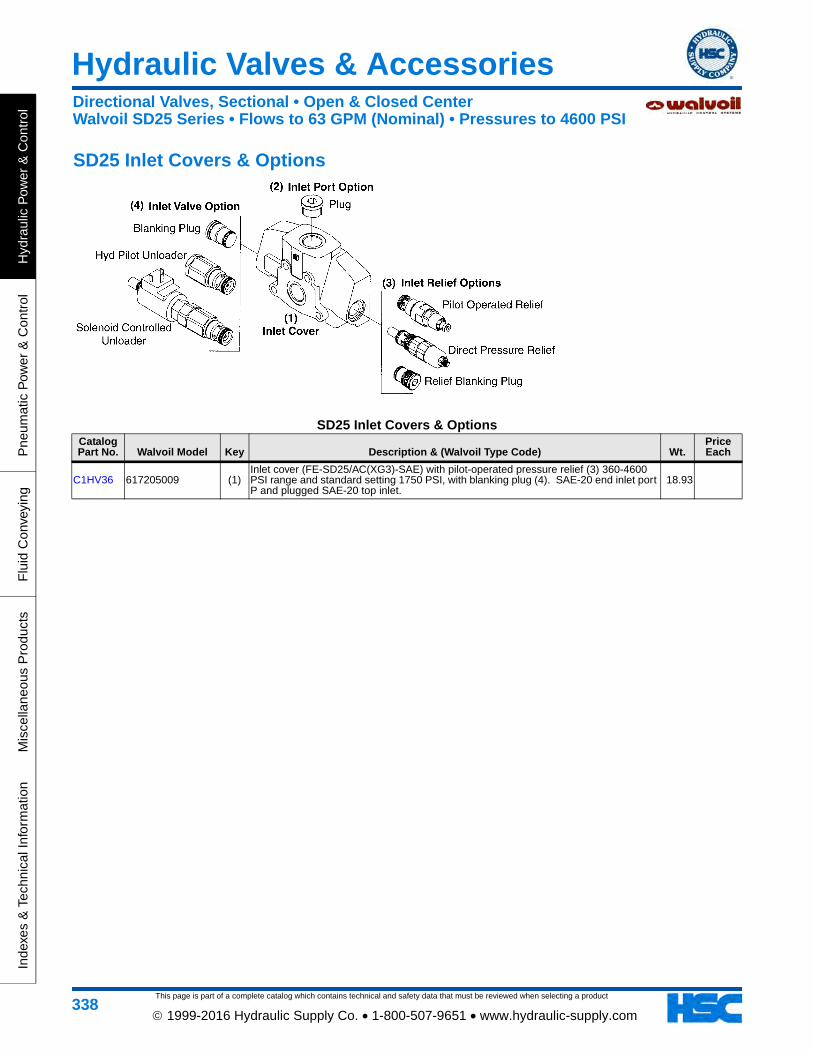
This page is part of a complete catalog which contains technical and safety data that must be reviewed when selecting a product
Hydraulic Valves & Accessories
Hyd
raul
ic P
ower
& C
ontr
olP
neum
atic
Pow
er &
Con
trol
Flu
id C
onve
ying
Mis
cella
neou
s P
rodu
cts
Inde
xes
& T
echn
ical
Info
rmat
ion
338 1999-2016 Hydraulic Supply Co. • 1-800-507-9651 • www.hydraulic-supply.com
SD25 Inlet Covers & Options
SD25 Inlet Covers & OptionsCatalog Part No. Walvoil Model Key Description & (Walvoil Type Code) Wt.
Price Each
C1HV36 617205009 (1)Inlet cover (FE-SD25/AC(XG3)-SAE) with pilot-operated pressure relief (3) 360-4600 PSI range and standard setting 1750 PSI, with blanking plug (4). SAE-20 end inlet port P and plugged SAE-20 top inlet.
18.93
Directional Valves, Sectional • Open & Closed CenterWalvoil SD25 Series • Flows to 63 GPM (Nominal) • Pressures to 4600 PSI

This page is part of a complete catalog which contains technical and safety data that must be reviewed when selecting a product
Hydraulic Valves & Accessories
Hydraulic P
ower &
Control
Pneum
atic Pow
er & C
ontrolF
luid Conveying
Miscellaneous P
roductsIndexes &
Technical Information
339 1999-2016 Hydraulic Supply Co. • 1-800-507-9651 • www.hydraulic-supply.com
SD25 Working Sections & Options
SD25 Working Sections & OptionsCatalog Part No. Walvoil Model Key Description & (Walvoil Type Code) Wt.
Price Each
C1NE26 61H105001 (1)Working section (EL-SD25/P-18L-SAE), parallel circuit, 4way 3-pos A&B closed in neutral, complete with spring centering positioner (3), standard lever box (4) and blanking plugs (5). SAE-16 work ports. Does NOT include M12 thread handlever.
22.76
C1HS91 3CU2725100 (2) Spool (Type 2), 4-way 3-position, A & B open to tank in neutral 1.89
C1HS90 3CU2710420 (2) Spool (Type 1IM) for remote hydraulic kit, parallel circuit, 4way 3-pos A&B closed in neutral 1.73
C1HU86 5V11120000 (3) "A" side spool positioner (Type 11), 3 position detent kit 0.85
C1HT46 5IDR225700 (3) "A" side spool positioner (Type IM), remote hydraulic kit 2.61
C1HS92 3CU2725420 (3) "A" & "B" side spool positioner (Type 8IM), remote hydraulic actuator kit with spring centering 1.62
•C1HQ59 170013025 (II) Handlever (Type AL01/M12x250), for mechanical joystick, M12 thread x 250mm long, with black knob 0.50
Directional Valves, Sectional • Open & Closed CenterWalvoil SD25 Series • Flows to 63 GPM (Nominal) • Pressures to 4600 PSI

This page is part of a complete catalog which contains technical and safety data that must be reviewed when selecting a product
Hydraulic Valves & Accessories
Hyd
raul
ic P
ower
& C
ontr
olP
neum
atic
Pow
er &
Con
trol
Flu
id C
onve
ying
Mis
cella
neou
s P
rodu
cts
Inde
xes
& T
echn
ical
Info
rmat
ion
340 1999-2016 Hydraulic Supply Co. • 1-800-507-9651 • www.hydraulic-supply.com
SD25 Outlet Cover & Options
SD25 Outlet Cover & OptionsCatalog Part No. Walvoil Model Key Description & (Walvoil Type Code) Wt.
Price Each
C1HV37 617305002 (1) Outlet cover (FS-SD25/RC-SAE), SAE-20 end outlet port T, plugged SAE-20 top outlet, machined for optional power beyond/closed center conversion 15.50
C1HT31 4TAP426612 (3) G 3/4 plug for power beyond / closed center option 0.08
SD25 Tie Rod & Mounting Bracket Kits
SD25 Tie Rod & Mounting Bracket KitsCatalog Part No. Walvoil Model Key Description & (Walvoil Type Code) Wt.
Price Each
C1HU61 5TIR112234 (1) Tie rod kit for a 1-section valve assembly 2.16
C1HU62 5TIR112296 (1) Tie rod kit for a 2-section valve assembly 2.63
Directional Valves, Sectional • Open & Closed CenterWalvoil SD25 Series • Flows to 63 GPM (Nominal) • Pressures to 4600 PSI
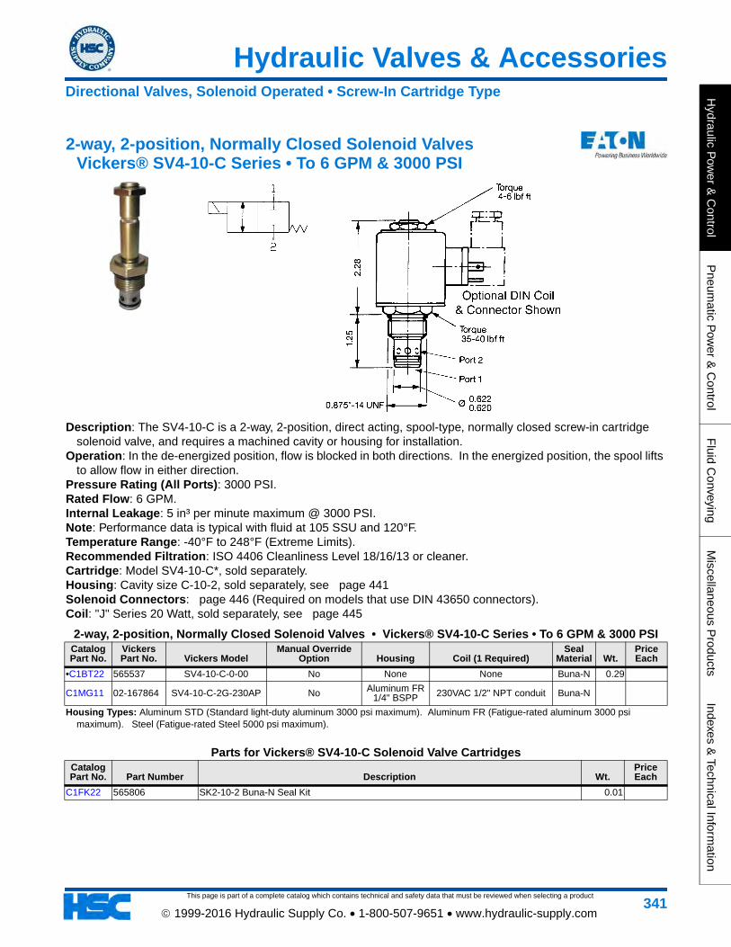
Hydraulic Valves & Accessories
This page is part of a complete catalog which contains technical and safety data that must be reviewed when selecting a product
Hydraulic P
ower &
Control
Pneum
atic Pow
er & C
ontrolF
luid Conveying
Miscellaneous P
roductsIndexes &
Technical Information
341 1999-2016 Hydraulic Supply Co. • 1-800-507-9651 • www.hydraulic-supply.com
2-way, 2-position, Normally Closed Solenoid Valves Vickers® SV4-10-C Series • To 6 GPM & 3000 PSI
Description: The SV4-10-C is a 2-way, 2-position, direct acting, spool-type, normally closed screw-in cartridge solenoid valve, and requires a machined cavity or housing for installation.
Operation: In the de-energized position, flow is blocked in both directions. In the energized position, the spool lifts to allow flow in either direction.
Pressure Rating (All Ports): 3000 PSI. Rated Flow: 6 GPM. Internal Leakage: 5 in³ per minute maximum @ 3000 PSI. Note: Performance data is typical with fluid at 105 SSU and 120°F. Temperature Range: -40°F to 248°F (Extreme Limits). Recommended Filtration: ISO 4406 Cleanliness Level 18/16/13 or cleaner. Cartridge: Model SV4-10-C*, sold separately. Housing: Cavity size C-10-2, sold separately, see page 441Solenoid Connectors: page 446 (Required on models that use DIN 43650 connectors). Coil: "J" Series 20 Watt, sold separately, see page 445
2-way, 2-position, Normally Closed Solenoid Valves • Vickers® SV4-10-C Series • To 6 GPM & 3000 PSICatalog Part No.
Vickers Part No. Vickers Model
Manual Override Option Housing Coil (1 Required)
Seal Material Wt.
Price Each
•C1BT22 565537 SV4-10-C-0-00 No None None Buna-N 0.29
C1MG11 02-167864 SV4-10-C-2G-230AP No Aluminum FR 1/4" BSPP 230VAC 1/2" NPT conduit Buna-N
Housing Types: Aluminum STD (Standard light-duty aluminum 3000 psi maximum). Aluminum FR (Fatigue-rated aluminum 3000 psi maximum). Steel (Fatigue-rated Steel 5000 psi maximum).
Parts for Vickers® SV4-10-C Solenoid Valve CartridgesCatalog Part No. Part Number Description Wt.
Price Each
C1FK22 565806 SK2-10-2 Buna-N Seal Kit 0.01
Directional Valves, Solenoid Operated • Screw-In Cartridge Type

This page is part of a complete catalog which contains technical and safety data that must be reviewed when selecting a product
Hydraulic Valves & Accessories
Hyd
raul
ic P
ower
& C
ontr
olP
neum
atic
Pow
er &
Con
trol
Flu
id C
onve
ying
Mis
cella
neou
s P
rodu
cts
Inde
xes
& T
echn
ical
Info
rmat
ion
342 1999-2016 Hydraulic Supply Co. • 1-800-507-9651 • www.hydraulic-supply.com
3-way, 2-position Solenoid Valves Vickers® SV4B-12-3 Series • To 11 GPM & 3000 PSI
Description: The SV4B-12-3 is a 3-way, 2-position, spool-type, direct acting screw-in cartridge solenoid valve, and requires a machined cavity or housing for installation.
Operation: In the de-energized position, this valve allows flow from port 1 to port 2 while port 3 is blocked. In the energized position, flow is allowed from port 2 to port 3 while port 1 is blocked.
Pressure Rating (All Ports): 3000 PSI. Rated Flow: 11 GPM. Internal Leakage: 21.5 in³/min max @ 3000 psi Temperature Range: -40°F to 248°F Recommended Filtration: ISO 4406 Cleanliness Level 18/16/13 or cleaner. Cartridge: Model SV4B-12-3*, sold separately. Housing: Cavity size C-12-3, sold separately, see page 442Coil: R Series, sold separately, see page 445Solenoid Connectors: page 446 (Required on models that use DIN 43650 connectors).
3-way, 2-position Solenoid Valves • Vickers® SV4B-12-3 Series • To 11 GPM & 3000 PSICatalog Part No. Vickers Part No. Vickers Model Housing Coil (1 Required)
Seal Material Wt.
Price Each
C1MG20 02-200192 SV4B-12-3P-0-00 None None Buna-N 1.90
Directional Valves, Solenoid Operated • Screw-In Cartridge Type

Hydraulic Valves & Accessories
This page is part of a complete catalog which contains technical and safety data that must be reviewed when selecting a product
Hydraulic P
ower &
Control
Pneum
atic Pow
er & C
ontrolF
luid Conveying
Miscellaneous P
roductsIndexes &
Technical Information
343 1999-2016 Hydraulic Supply Co. • 1-800-507-9651 • www.hydraulic-supply.com
2-way, 2-position, Normally Closed Solenoid Valves Vickers® SV5-8-C Series • To 6 GPM & 3000 PSI
Description: The SV5-8-C is a 2-way, 2-position, poppet type, pilot operated, normally closed screw-in cartridge solenoid valve, and requires a machined cavity or housing for installation. This valve is used in applications requiring low leakage.
Operation: In the de-energized position, the SV5-8-C blocks flow from port 2 to port 1, and free flow is allowed from port 1 to port 2. In the energized position, flow from port 1 to port 2 is restricted and free flow is allowed from port 2 to port 1.
Pressure Rating (All Ports): 3000 PSI. Rated Flow: 6 GPM. Internal Leakage: Less than 5 drops per minute maximum @ 3000 PSI. Note: Performance data is typical with fluid at 105 SSU and 120°F. Temperature Range: -40°F to 248°F (Extreme Limits). Recommended Filtration: ISO 4406 Cleanliness Level 18/16/13 or cleaner. Cartridge: Model SV5-8-C*, sold separately. Housing: Cavity size C-8-2, sold separately, see page 441Solenoid Connectors: page 446 (Required on models that use DIN 43650 connectors). Coil: "S" Series 16 Watt, sold separately, see page 445
2-way, 2-position, Normally Closed Solenoid Valves • Vickers® SV5-8-C Series • To 6 GPM & 3000 PSICatalog Part No.
Vickers Part No. Vickers Model
Manual Override Option Housing Coil (1 Required)
Seal Material Wt.
Price Each
•C1ZZ82 02-160759 SV5-8-C-0-00 No None None Buna-N 0.22
Housing Types: Aluminum STD (Standard light-duty aluminum 3000 psi maximum). Aluminum FR (Fatigue-rated aluminum 3000 psi maximum). Steel (Fatigue-rated Steel 5000 psi maximum).
Directional Valves, Solenoid Operated • Screw-In Cartridge Type

This page is part of a complete catalog which contains technical and safety data that must be reviewed when selecting a product
Hydraulic Valves & Accessories
Hyd
raul
ic P
ower
& C
ontr
olP
neum
atic
Pow
er &
Con
trol
Flu
id C
onve
ying
Mis
cella
neou
s P
rodu
cts
Inde
xes
& T
echn
ical
Info
rmat
ion
344 1999-2016 Hydraulic Supply Co. • 1-800-507-9651 • www.hydraulic-supply.com
2-way, 2-position, Normally Closed Solenoid Valves Vickers® SV3-10-C Series • To 12 GPM & 3000 PSI
Description: The SV3-10-C is a 2-way, 2-position, pilot operated, poppet-type, normally closed screw-in cartridge solenoid valve, and requires a machined cavity or housing for installation.
Operation: In the de-energized position, flow is blocked from port 2 to port 1 and free flow is allowed from port 1 to port 2. In the energized position, the poppet lifts to allow flow in either direction.
Pressure Rating (All Ports): 3000 PSI. Rated Flow: 12 GPM. Internal Leakage: Less than 5 drops per minute maximum @ 3000 PSI. Note: Performance data is typical with fluid at 105 SSU and 120°F. Temperature Range: -40°F to 248°F (Extreme Limits). Recommended Filtration: ISO 4406 Cleanliness Level 18/16/13 or cleaner. Cartridge: Model SV3-10-C*, sold separately. Housing: Cavity size C-10-2, sold separately, see page 441Solenoid Connectors: page 446 (Required on models that use DIN 43650 connectors). Coil: "J" Series 20 Watt, sold separately, see page 445
2-way, 2-position, Normally Closed Solenoid Valves • Vickers® SV3-10-C Series • To 12 GPM & 3000 PSICatalog Part No.
Vickers Part No. Vickers Model
Manual Override Option Housing Coil (1 Required)
Seal Material Wt.
Price Each
•C1BT21 565536 SV3-10-C-0-00 No None None Buna-N 0.31
C1MZ62 565657 SV3-10-C-0-12DG No None 12VDC Buna-N
Housing Types: Aluminum STD (Standard light-duty aluminum 3000 psi maximum). Aluminum FR (Fatigue-rated aluminum 3000 psi maximum). Steel (Fatigue-rated Steel 5000 psi maximum).
Directional Valves, Solenoid Operated • Screw-In Cartridge Type

Hydraulic Valves & Accessories
This page is part of a complete catalog which contains technical and safety data that must be reviewed when selecting a product
Hydraulic P
ower &
Control
Pneum
atic Pow
er & C
ontrolF
luid Conveying
Miscellaneous P
roductsIndexes &
Technical Information
345 1999-2016 Hydraulic Supply Co. • 1-800-507-9651 • www.hydraulic-supply.com
2-way, 2-position, Normally Closed Solenoid Valves Vickers® SV1-10-C Series • To 12 GPM & 3000 PSI
Description: The SV1-10-C is a 2-way, 2-position, pilot operated, poppet-type, normally closed screw-in cartridge solenoid valve, and requires a machined cavity or housing for installation.
Operation: In the de-energized position, flow is blocked from port 2 to port 1 and free flow is allowed from port 1 to port 2. In the energized position, flow from port 1 to port 2 is restricted while free flow is allowed from port 2 to port 1.
Pressure Rating (All Ports): 3000 PSI. Rated Flow: 12 GPM. Internal Leakage: Port 2 to Port 1: 5 drops per minute maximum @ 3000 PSI. Note: Performance data is typical with fluid at 105 SSU and 120°F. Temperature Range: -40°F to 248°F (Extreme Limits). Recommended Filtration: ISO 4406 Cleanliness Level 18/16/13 or cleaner. Cartridge: Model SV1-10-C*, sold separately. Housing: Cavity size C-10-2, sold separately, see page 441Solenoid Connectors: page 446 (Required on models that use DIN 43650 connectors). Coil: "J" Series 20 Watt, sold separately, see page 445
2-way, 2-position, Normally Closed Solenoid Valves • Vickers® SV1-10-C Series • To 12 GPM & 3000 PSICatalog Part No.
Vickers Part No. Vickers Model
Manual Override Option Housing Coil (1 Required)
Seal Material Wt.
Price Each
•C1BT20 565534 SV1-10-C-0-00 No None None Buna-N 0.30
Housing Types: Aluminum STD (Standard light-duty aluminum 3000 psi maximum). Aluminum FR (Fatigue-rated aluminum 3000 psi maximum). Steel (Fatigue-rated Steel 5000 psi maximum).
Directional Valves, Solenoid Operated • Screw-In Cartridge Type

This page is part of a complete catalog which contains technical and safety data that must be reviewed when selecting a product
Hydraulic Valves & Accessories
Hyd
raul
ic P
ower
& C
ontr
olP
neum
atic
Pow
er &
Con
trol
Flu
id C
onve
ying
Mis
cella
neou
s P
rodu
cts
Inde
xes
& T
echn
ical
Info
rmat
ion
346 1999-2016 Hydraulic Supply Co. • 1-800-507-9651 • www.hydraulic-supply.com
2-way, 2-position, Normally Closed Solenoid Valves Vickers® SV3-12-C Series • To 30 GPM & 3000 PSI
Description: This is a 2-way, 2-position, poppet type, pilot operated, normally closed solenoid valve. This valve is used in applications requiring low leakage, such as load holding applications or as a general purpose diverter or dump valve.
Operation: In the de-energized position the valve blocks flow from port 2 to 1 and free flow is allowed from port 1 to 2. When the solenoid is energized the pilot poppet is pulled off the seat allowing the valve to open in both directions.
Pressure Rating (All Ports): 3000 PSI. Rated Flow: 30 GPM. Internal Leakage: Port 2 to Port 1: Less than 5 drops/min, max @ 3000 PSI. Note: Performance data is typical with fluid at 105 SSU and 120°F. Temperature Range: -40° to 248°F (Extreme Limits). Recommended Filtration: ISO 4406 Cleanliness Level 18/16/13 or cleaner. Cartridge: Model SV3-12-C*, sold separately Housing: Cavity size C-12-2 or C-12-2U sold separately. Add “U” after number if undercut is required. If undercut
is not specified, expect 10 PSI @ 15 GPM and 20 PSI @ 30 GPM higher pressure drop, see page 441Solenoid Connectors: page 446 (Required on models that use DIN 43650 connectors). Coil: J series, 23 Watt, sold separately, see page 445
2-way, 2-position, Normally Closed Solenoid Valves • Vickers® SV3-12-C Series • To 30 GPM & 3000 PSICatalog Part No. Vickers Part No. Vickers Model Housing Coil (1 Required)
Seal Material Wt.
Price Each
C1FQ33 02-161062 SV3-12-C-0-00 None None Buna-N 0.51
Directional Valves, Solenoid Operated • Screw-In Cartridge Type

Hydraulic Valves & Accessories
This page is part of a complete catalog which contains technical and safety data that must be reviewed when selecting a product
Hydraulic P
ower &
Control
Pneum
atic Pow
er & C
ontrolF
luid Conveying
Miscellaneous P
roductsIndexes &
Technical Information
347 1999-2016 Hydraulic Supply Co. • 1-800-507-9651 • www.hydraulic-supply.com
2-way, 2-position, Normally Closed Solenoid Valves Vickers® SV13-10-C Series • To 12 GPM & 5000 PSI
Description: This is a 2-way, 2-position, poppet type, high pressure, pilot operated, normally closed solenoid valve. This valve is used in applications requiring low leakage, such as load holding applications or as a general purpose diverter or dump valve.
Operation: In the de-energized position the valve blocks flow from port 2 to 1 and free flow is allowed from port 1 to 2. When the solenoid is energized the pilot poppet is pulled off the seat allowing the valve to open in both directions.
Pressure Rating (All Ports): 5000 PSI. (CAUTION: Pressures over 3000 PSI require steel housing or manifold). Rated Flow: 12 GPM. Internal Leakage: 5 drops per minute maximum @ 5000 PSI. Note: Performance data is typical with fluid at 105 SSU and 120°F. Temperature Range: -40° to 212°F (Extreme Limits). Recommended Filtration: ISO 4406 Cleanliness Level 18/16/13 or cleaner. Cartridge: Model SV13-10-C*, sold separately. Housing: Cavity size C-10-2, sold separately, see page 441Solenoid Connectors: page 446 (Required on models that use DIN 43650 connectors). Coil: "H" - 10 Series, 29 Watt, sold separately, see page 445
2-way, 2-position, Normally Closed Solenoid Valves • Vickers® SV13-10-C Series • To 12 GPM & 5000 PSICatalog Part No. Vickers Part No. Vickers Model Housing Coil (1 Required)
Seal Material Wt.
Price Each
C1MG12 02-175805 SV13-10-C-0-00 None None Buna-N
Housing Types: Aluminum STD (Standard light-duty aluminum 3000 psi maximum). Aluminum FR (Fatigue-rated aluminum 3000 psimaximum). Steel (Fatigue-rated Steel 5000 psi maximum).
Directional Valves, Solenoid Operated • Screw-In Cartridge Type

This page is part of a complete catalog which contains technical and safety data that must be reviewed when selecting a product
Hydraulic Valves & Accessories
Hyd
raul
ic P
ower
& C
ontr
olP
neum
atic
Pow
er &
Con
trol
Flu
id C
onve
ying
Mis
cella
neou
s P
rodu
cts
Inde
xes
& T
echn
ical
Info
rmat
ion
348 1999-2016 Hydraulic Supply Co. • 1-800-507-9651 • www.hydraulic-supply.com
2-way, 2-position, Normally Closed Solenoid Valves Vickers® SBV11-10-C Series • To 20 GPM & 5000 PSI
Description: The SBV11-10-C is a 2-way, 2-position, bi-directional, pilot operated, poppet-type, normally closed screw-in cartridge solenoid valve, and requires a machined cavity or housing for installation.
Operation: In the de-energized position, flow is blocked in both directions. In the energized position, flow is allowed in both directions.
Pressure Rating (All Ports): 5000 PSI. (CAUTION: Pressures over 3000 PSI require steel housing or manifold). Rated Flow: 20 GPM. Internal Leakage: 5 drops per minute maximum @ 5000 PSI. Note: Performance data is typical with fluid at 105 SSU and 120°F. Temperature Range: -40°F to 212°F (Extreme Limits). Recommended Filtration: ISO 4406 Cleanliness Level 18/16/13 or cleaner. Cartridge: Model SBV11-10-C*, sold separately. Housing: Cavity size C-10-2, sold separately, see page 441Solenoid Connectors: page 446 (Required on models that use DIN 43650 connectors). Coil: "H" Series 26 Watt, sold separately, see page 445
2-way, 2-position, Normally Closed Solenoid Valves • Vickers® SBV11-10-C Series • To 20 GPM & 5000 PSICatalog Part No. Vickers Part No. Vickers Model Housing Coil (1 Required)
Seal Material Wt.
Price Each
C1HY32 02-177580 SBV11-10-C-0-00 None None Buna-N 0.39
Housing Types: Aluminum STD (Standard light-duty aluminum 3000 psi maximum). Aluminum FR (Fatigue-rated aluminum 3000 psi maximum). Steel (Fatigue-rated Steel 5000 psi maximum).
Directional Valves, Solenoid Operated • Screw-In Cartridge Type

Hydraulic Valves & Accessories
This page is part of a complete catalog which contains technical and safety data that must be reviewed when selecting a product
Hydraulic P
ower &
Control
Pneum
atic Pow
er & C
ontrolF
luid Conveying
Miscellaneous P
roductsIndexes &
Technical Information
349 1999-2016 Hydraulic Supply Co. • 1-800-507-9651 • www.hydraulic-supply.com
2-way, 2-position, Normally Closed Solenoid Valves Vickers® SBV11-12-C Series • To 30 GPM & 5000 PSI
Description: The SBV11-12-C is a 2-way, 2-position, bi-directional, pilot operated, poppet-type, normally closed screw-in cartridge solenoid valve, and requires a machined cavity or housing for installation.
Operation: In the de-energized position, flow is blocked in both directions. In the energized position, flow is allowed in both directions.
Pressure Rating (All Ports): 5000 PSI. (CAUTION: Pressures over 3000 PSI require steel housing or manifold). Rated Flow: 30 GPM Internal Leakage: 5 drops per minute maximum @ 5000 PSI. Temperature Range: -40°F to 212°F Recommended Filtration: ISO 4406 Cleanliness Level 18/16/13 or cleaner. Cartridge: Model SBV11-12-C*, sold separately. Housing: Cavity size C-12-2, sold separately, see page 441Coil: H Series, sold separately, see page 445Solenoid Connectors: page 446 (Required on models that use DIN 43650 connectors).
2-way, 2-position, Normally Closed Solenoid Valves • Vickers® SBV11-12-C Series • To 30 GPM & 5000 PSICatalog Part No. Vickers Part No. Vickers Model Housing Coil (1 Required)
Seal Material Wt.
Price Each
C1LW47 02-177576 SBV11-12-C-0-00 None None Buna-N 0.59
Directional Valves, Solenoid Operated • Screw-In Cartridge Type

This page is part of a complete catalog which contains technical and safety data that must be reviewed when selecting a product
Hydraulic Valves & Accessories
Hyd
raul
ic P
ower
& C
ontr
olP
neum
atic
Pow
er &
Con
trol
Flu
id C
onve
ying
Mis
cella
neou
s P
rodu
cts
Inde
xes
& T
echn
ical
Info
rmat
ion
350 1999-2016 Hydraulic Supply Co. • 1-800-507-9651 • www.hydraulic-supply.com
2-way, 2-position, Normally Closed Solenoid Valves Vickers® SV1-16-C Series • To 35 GPM & 3000 PSI
Description: The SV1-16-C is a 2-way, 2-position, pilot operated, poppet-type, normally closed screw-in cartridge solenoid valve, and requires a machined cavity or housing for installation.
Operation: In the de-energized position, flow is blocked from port 2 to port 1 and free flow is allowed from port 1 to port 2. In the energized position, bi-directional flow is allowed between port 1 and port 2.
Pressure Rating (All Ports): 3000 PSI. Rated Flow: 35 GPM. Internal Leakage: Port 2 to Port 1: 5 drops per minute maximum @ 3000 PSI. Note: Performance data is typical with fluid at 105 SSU and 120°F. Temperature Range: -40°F to 248°F (Extreme Limits). Recommended Filtration: ISO 4406 Cleanliness Level 18/16/13 or cleaner. Cartridge: Model SV1-16-C*, sold separately. Housing: Cavity size C-16-2, sold separately, see page 441Solenoid Connectors: page 446 (Required on models that use DIN 43650 connectors). Coil: "J" Series 20 Watt, sold separately, see page 445
2-way, 2-position, Normally Closed Solenoid Valves • Vickers® SV1-16-C Series • To 35 GPM & 3000 PSICatalog Part No.
Vickers Part No. Vickers Model
Manual Override Option Housing Coil (1 Required)
Seal Material Wt.
Price Each
•C1BT23 565538 SV1-16-C-0-00 No None None Buna-N 0.72
Housing Types: Aluminum STD (Standard light-duty aluminum 3000 psi maximum). Aluminum FR (Fatigue-rated aluminum 3000 psi maximum). Steel (Fatigue-rated Steel 5000 psi maximum).
Directional Valves, Solenoid Operated • Screw-In Cartridge Type

Hydraulic Valves & Accessories
This page is part of a complete catalog which contains technical and safety data that must be reviewed when selecting a product
Hydraulic P
ower &
Control
Pneum
atic Pow
er & C
ontrolF
luid Conveying
Miscellaneous P
roductsIndexes &
Technical Information
351 1999-2016 Hydraulic Supply Co. • 1-800-507-9651 • www.hydraulic-supply.com
2-way, 2-position, Normally Closed Solenoid Valves Vickers® SV13-16-C Series • To 35 GPM & 5000 PSI
Description: The SV13-16-C is a 2-way, 2-position, pilot operated, poppet-type, normally closed screw-in cartridge solenoid valve, and requires a machined cavity or housing for installation.
Operation: In the de-energized position, flow is blocked from port 2 to port 1 and free flow is allowed from port 1 to port 2. In the energized position, the poppet lifts to allow flow in either direction.
Pressure Rating (All Ports): 5000 PSI Rated Flow: 35 GPM Internal Leakage: Less than 5 drops per minute maximum @ 5000 PSI. Temperature Range: -40° to 212°F Recommended Filtration: ISO 4406 Cleanliness Level 18/16/13 or cleaner. Cartridge: Model SV13-16-C*, sold separately. Housing: Cavity size C-16-2, sold separately, see page 441Coil: H series, sold separately, see page 445Solenoid Connectors: page 446 (Required on models that use DIN 43650 connectors).
2-way, 2-position, Normally Closed Solenoid Valves • Vickers® SV13-16-C Series • To 35 GPM & 5000 PSICatalog Part No. Vickers Part No. Vickers Model Housing Coil (1 Required)
Seal Material Wt.
Price Each
C1MG17 02-175823 SV13-16-C-0-00 None None Buna-N 0.85
Directional Valves, Solenoid Operated • Screw-In Cartridge Type

This page is part of a complete catalog which contains technical and safety data that must be reviewed when selecting a product
Hydraulic Valves & Accessories
Hyd
raul
ic P
ower
& C
ontr
olP
neum
atic
Pow
er &
Con
trol
Flu
id C
onve
ying
Mis
cella
neou
s P
rodu
cts
Inde
xes
& T
echn
ical
Info
rmat
ion
352 1999-2016 Hydraulic Supply Co. • 1-800-507-9651 • www.hydraulic-supply.com
2-way, 2-position, Normally Closed Solenoid Valves Vickers® SV2-20-C Series • To 60 GPM & 3000 PSI
Description: The SV2-20-C is a 2-way, 2-position, pilot operated, poppet-type, normally closed screw-in cartridge solenoid valve, and requires a machined cavity or housing for installation.
Operation: In the de-energized position, flow is blocked from port 2 to port 1 and free flow is allowed from port 1 to port 2. In the energized position, free flow is allowed between both ports.
Pressure Rating (All Ports): 3000 PSI. Rated Flow: 60 GPM. Internal Leakage: Port 2 to Port 1: Less than 5 drops per minute maximum @ 3000 PSI. Note: Performance data is typical with fluid at 105 SSU and 120°F. Temperature Range: -40°F to 248°F (Extreme Limits). Recommended Filtration: ISO 4406 Cleanliness Level 18/16/13 or cleaner. Cartridge: Model SV2-20-C*, sold separately. Housing: Cavity size C-20-2, sold separately, see page 441Solenoid Connectors: page 446 (Required on models that use DIN 43650 connectors). Coil: "J" Series 20 Watt, sold separately, see page 445
2-way, 2-position, Normally Closed Solenoid Valves • Vickers® SV2-20-C Series • To 60 GPM & 3000 PSICatalog Part No.
Vickers Part No. Vickers Model
Manual Override Option Housing Coil (1 Required)
Seal Material Wt.
Price Each
C1FA73 565539 SV2-20-C-0-00 No None None Buna-N 1.16
Housing Types: Aluminum STD (Standard light-duty aluminum 3000 psi maximum). Aluminum FR (Fatigue-rated aluminum 3000 psi maximum). Steel (Fatigue-rated Steel 5000 psi maximum).
Directional Valves, Solenoid Operated • Screw-In Cartridge Type

Hydraulic Valves & Accessories
This page is part of a complete catalog which contains technical and safety data that must be reviewed when selecting a product
Hydraulic P
ower &
Control
Pneum
atic Pow
er & C
ontrolF
luid Conveying
Miscellaneous P
roductsIndexes &
Technical Information
353 1999-2016 Hydraulic Supply Co. • 1-800-507-9651 • www.hydraulic-supply.com
2-way, 2-position, Normally Closed Solenoid Valves Vickers® SV13-20-C Series • To 60 GPM & 5000 PSI
Description: The SV13-20-C is a 2-way, 2-position, pilot operated, poppet-type, normally closed screw-in cartridge solenoid valve, and requires a machined cavity or housing for installation.
Operation: In the de-energized position, flow is blocked from port 2 to port 1 and free flow is allowed from port 1 to port 2. In the energized position, the poppet lifts to allow flow in either direction.
Pressure Rating (All Ports): 5000 PSI Rated Flow: 60 GPM. Internal Leakage: Less than 5 drops per minute maximum @ 5000 PSI. Temperature Range: -40° to 212°F Recommended Filtration: ISO 4406 Cleanliness Level 18/16/13 or cleaner. Cartridge: Model SV13-20-C*, sold separately. Housing: Cavity size C-20-2, sold separately, see page 441Coil: H series, sold separately, see page 445Solenoid Connectors: page 446 (Required on models that use DIN 43650 connectors).
2-way, 2-position, Normally Closed Solenoid Valves • Vickers® SV13-20-C Series • To 60 GPM & 5000 PSICatalog Part No. Vickers Part No. Vickers Model Housing Coil (1 Required)
Seal Material Wt.
Price Each
C1MG15 02-175819 SV13-20-C-0-00 None None Buna-N 1.37
Directional Valves, Solenoid Operated • Screw-In Cartridge Type

This page is part of a complete catalog which contains technical and safety data that must be reviewed when selecting a product
Hydraulic Valves & Accessories
Hyd
raul
ic P
ower
& C
ontr
olP
neum
atic
Pow
er &
Con
trol
Flu
id C
onve
ying
Mis
cella
neou
s P
rodu
cts
Inde
xes
& T
echn
ical
Info
rmat
ion
354 1999-2016 Hydraulic Supply Co. • 1-800-507-9651 • www.hydraulic-supply.com
2-way, 2-position, Normally Open Solenoid Valves Vickers® SV4-10-O Series • To 6 GPM & 3000 PSI
Description: The SV4-10-O is a 2-way, 2-position, spool-type, direct acting, normally open screw-in cartridge solenoid valve, and requires a machined cavity or housing for installation.
Operation: In the de-energized position, this valve allows bi-directional flow between port 1 and port 2. In the energized position both ports are closed.
Pressure Rating (All Ports): 3000 PSI. Rated Flow: 6 GPM. Internal Leakage: Port 2 to Port 1: 5 in³ per minute maximum @ 3000 PSI with valve energized. Note: Performance data is typical with fluid at 105 SSU and 120°F. Temperature Range: -40°F to 248°F (Extreme Limits). Recommended Filtration: ISO 4406 Cleanliness Level 18/16/13 or cleaner. Cartridge: Model SV4-10-O*, sold separately. Housing: Cavity size C-10-2, sold separately, see page 441Solenoid Connectors: page 446 (Required on models that use DIN 43650 connectors). Coil: "J" Series 20 Watt, sold separately, see page 445
2-way, 2-position, Normally Open Solenoid Valves • Vickers® SV4-10-O Series • To 6 GPM & 3000 PSICatalog Part No.
Vickers Part No. Vickers Model
Manual Override Option Housing Coil (1 Required)
Seal Material Wt.
Price Each
•C1BT25 565542 SV4-10-O-0-00 No None None Buna-N 0.30
Housing Types: Aluminum STD (Standard light-duty aluminum 3000 psi maximum). Aluminum FR (Fatigue-rated aluminum 3000 psi maximum). Steel (Fatigue-rated Steel 5000 psi maximum).
Parts for Vickers® SV4-10-O Solenoid Valve CartridgesCatalog Part No. Part Number Description Wt.
Price Each
C1FK22 565806 SK2-10-2 Buna-N Seal Kit 0.01
Directional Valves, Solenoid Operated • Screw-In Cartridge Type

Hydraulic Valves & Accessories
This page is part of a complete catalog which contains technical and safety data that must be reviewed when selecting a product
Hydraulic P
ower &
Control
Pneum
atic Pow
er & C
ontrolF
luid Conveying
Miscellaneous P
roductsIndexes &
Technical Information
355 1999-2016 Hydraulic Supply Co. • 1-800-507-9651 • www.hydraulic-supply.com
2-way, 2-position, Normally Open Solenoid Valves Vickers® SV5-8-O Series • To 6 GPM & 3000 PSI
Description: The SV5-8-O is a 2-way, 2-position, poppet-type, pilot operated, normally open screw-in cartridge solenoid valve, and requires a machined cavity or housing for installation. This valve is used in applications requiring low leakage.
Operation: In the de-energized position, this valve allows free flow from port 2 to port 1, and restricted flow from port 1 to port 2. In the energized position, flow is blocked from port 2 to port 1, and free flow is allowed from port 1 to port 2.
Pressure Rating (All Ports): 3000 PSI. Rated Flow: 6 GPM. Internal Leakage: Less than 5 drops per minute maximum @ 3000 PSI with valve energized. Note: Performance data is typical with fluid at 105 SSU and 120°F. Temperature Range: -40°F to 248°F (Extreme Limits). Recommended Filtration: ISO 4406 Cleanliness Level 18/16/13 or cleaner. Cartridge: Model SV5-8-O*, sold separately. Housing: Cavity size C-8-2, sold separately, see page 441Solenoid Connectors: page 446 (Required on models that use DIN 43650 connectors). Coil: "S" Series 16 Watt, sold separately, see page 445
2-way, 2-position, Normally Open Solenoid Valves • Vickers® SV5-8-O Series • To 6 GPM & 3000 PSICatalog Part No.
Vickers Part No. Vickers Model
Manual Override Option Housing Coil (1 Required)
Seal Material Wt.
Price Each
•C1AD17 02-160761 SV5-8-0-0-00 No None None Buna-N 0.29
Housing Types: Aluminum STD (Standard light-duty aluminum 3000 psi maximum). Aluminum FR (Fatigue-rated aluminum 3000 psi maximum). Steel (Fatigue-rated Steel 5000 psi maximum).
Directional Valves, Solenoid Operated • Screw-In Cartridge Type

This page is part of a complete catalog which contains technical and safety data that must be reviewed when selecting a product
Hydraulic Valves & Accessories
Hyd
raul
ic P
ower
& C
ontr
olP
neum
atic
Pow
er &
Con
trol
Flu
id C
onve
ying
Mis
cella
neou
s P
rodu
cts
Inde
xes
& T
echn
ical
Info
rmat
ion
356 1999-2016 Hydraulic Supply Co. • 1-800-507-9651 • www.hydraulic-supply.com
2-way, 2-position, Normally Open Solenoid Valves Vickers® SV3-10-O Series • To 12 GPM & 3000 PSI
Description: The SV3-10-O is a 2-way, 2-position, poppet-type, pilot operated, normally open screw-in cartridge solenoid valve, and requires a machined cavity or housing for installation. This valve is used in applications requiring low leakage.
Operation: In the de-energized position, this valve allows bi-directional flow between port 1 and port 2. In the energized position, flow is blocked from port 2 to port 1, and is allowed from port 1 to port 2 when spring force is overcome.
Pressure Rating (All Ports): 3000 PSI. Rated Flow: 12 GPM. Internal Leakage: Port 2 to Port 1: Less than 5 drops per minute maximum @ 3000 PSI with valve energized. Note: Performance data is typical with fluid at 105 SSU and 120°F. Temperature Range: -40°F to 248°F (Extreme Limits). Recommended Filtration: ISO 4406 Cleanliness Level 18/16/13 or cleaner. Cartridge: Model SV3-10-O*, sold separately. Housing: Cavity size C-10-2, sold separately, see page 441Solenoid Connectors: page 446 (Required on models that use DIN 43650 connectors). Coil: "J" Series 20 Watt, sold seperately, see page 445
2-way, 2-position, Normally Open Solenoid Valves • Vickers® SV3-10-O Series • To 12 GPM & 3000 PSICatalog Part No.
Vickers Part No. Vickers Model
Manual Override Option Housing Coil (1 Required)
Seal Material Wt.
Price Each
•C1BT24 565541 SV3-10-O-0-00 No None None Buna-N 0.37
Housing Types: Aluminum STD (Standard light-duty aluminum 3000 psi maximum). Aluminum FR (Fatigue-rated aluminum 3000 psi maximum). Steel (Fatigue-rated Steel 5000 psi maximum).
Directional Valves, Solenoid Operated • Screw-In Cartridge Type

Hydraulic Valves & Accessories
This page is part of a complete catalog which contains technical and safety data that must be reviewed when selecting a product
Hydraulic P
ower &
Control
Pneum
atic Pow
er & C
ontrolF
luid Conveying
Miscellaneous P
roductsIndexes &
Technical Information
357 1999-2016 Hydraulic Supply Co. • 1-800-507-9651 • www.hydraulic-supply.com
2-way, 2-position, Normally Open Solenoid Valves Vickers® SBV11-10-O Series • To 20 GPM & 5000 PSI
Description: The SBV11-10-O is a 2-way, 2-position, bi-directional, pilot operated, poppet-type, normally open screw-in cartridge solenoid valve, and requires a machined cavity or housing for installation.
Operation: In the de-energized position, flow is allowed in both directions. In the energized position, flow is blocked in both directions.
Pressure Rating (All Ports): 5000 PSI. (CAUTION: Pressures over 3000 PSI require steel housing or manifold). Rated Flow: 20 GPM. Internal Leakage: Port 1 to Port 2, or Port 2 to Port 1: 5 drops per minute maximum @ 5000 PSI. Note: Performance data is typical with fluid at 105 SSU and 120°F. Temperature Range: -40°F to 212°F (Extreme Limits). Recommended Filtration: ISO 4406 Cleanliness Level 18/16/13 or cleaner. Cartridge: Model SBV11-10-O*, sold separately. Housing: Cavity size C-10-2, sold separately, see page 441Solenoid Connectors: page 446 (Required on models that use DIN 43650 connectors). Coil: "H" Series 26 Watt, sold separately, see page 445
2-way, 2-position, Normally Open Solenoid Valves • Vickers® SBV11-10-O Series • To 20 GPM & 5000 PSICatalog Part No. Vickers Part No. Vickers Model Housing Coil (1 Required)
Seal Material Wt.
Price Each
C1HY31 02-177579 SBV11-10-0-0-00 None None Buna-N 0.39
Housing Types: Aluminum STD (Standard light-duty aluminum 3000 psi maximum). Aluminum FR (Fatigue-rated aluminum 3000 psi maximum). Steel (Fatigue-rated Steel 5000 psi maximum).
Directional Valves, Solenoid Operated • Screw-In Cartridge Type

This page is part of a complete catalog which contains technical and safety data that must be reviewed when selecting a product
Hydraulic Valves & Accessories
Hyd
raul
ic P
ower
& C
ontr
olP
neum
atic
Pow
er &
Con
trol
Flu
id C
onve
ying
Mis
cella
neou
s P
rodu
cts
Inde
xes
& T
echn
ical
Info
rmat
ion
358 1999-2016 Hydraulic Supply Co. • 1-800-507-9651 • www.hydraulic-supply.com
2-way, 2-position, Normally Open Solenoid Valves Vickers® SV3-12-O Series • To 30 GPM & 3000 PSI
Description: The SV3-12-O is a 2-way, 2-position, poppet-type, pilot operated, normally open screw-in cartridge solenoid valve, and requires a machined cavity or housing for installation.
Operation: In the de-energized position, this valve allows bi-directional flow between port 1 and port 2. In the energized position, flow is blocked from port 2 to port 1, and is allowed from port 1 to port 2 when spring force is overcome.
Pressure Rating (All Ports): 3000 PSI. Rated Flow: 30 GPM. Internal Leakage: Port 2 to Port 1: Less than 5 drops per minute maximum @ 3000 PSI with valve energized. Note: Performance data is typical with fluid at 105 SSU and 120°F. Temperature Range: -40°F to 248°F (Extreme Limits). Recommended Filtration: ISO 4406 Cleanliness Level 17/15/12 or cleaner. Cartridge: Model SV3-12-O*, sold separately. Housing: Cavity size C-12-2 or C-12-2U, sold separately, see page 441Solenoid Connectors: page 446 (Required on models that use DIN 43650 connectors). Coil: "J" Series 20 Watt, sold separately, see page 445
2-way, 2-position, Normally Open Solenoid Valves • Vickers® SV3-12-O Series • To 30 GPM & 3000 PSICatalog Part No.
Vickers Part No. Vickers Model
Manual Override Option Housing Coil (1 Required)
Seal Material Wt.
Price Each
C1FQ44 02-161311 SV3-12-O-0-00 No None None Buna-N 0.58
Housing Types: Aluminum STD (Standard light-duty aluminum 3000 psi maximum). Aluminum FR (Fatigue-rated aluminum 3000 psi maximum). Steel (Fatigue-rated Steel 5000 psi maximum).
Directional Valves, Solenoid Operated • Screw-In Cartridge Type
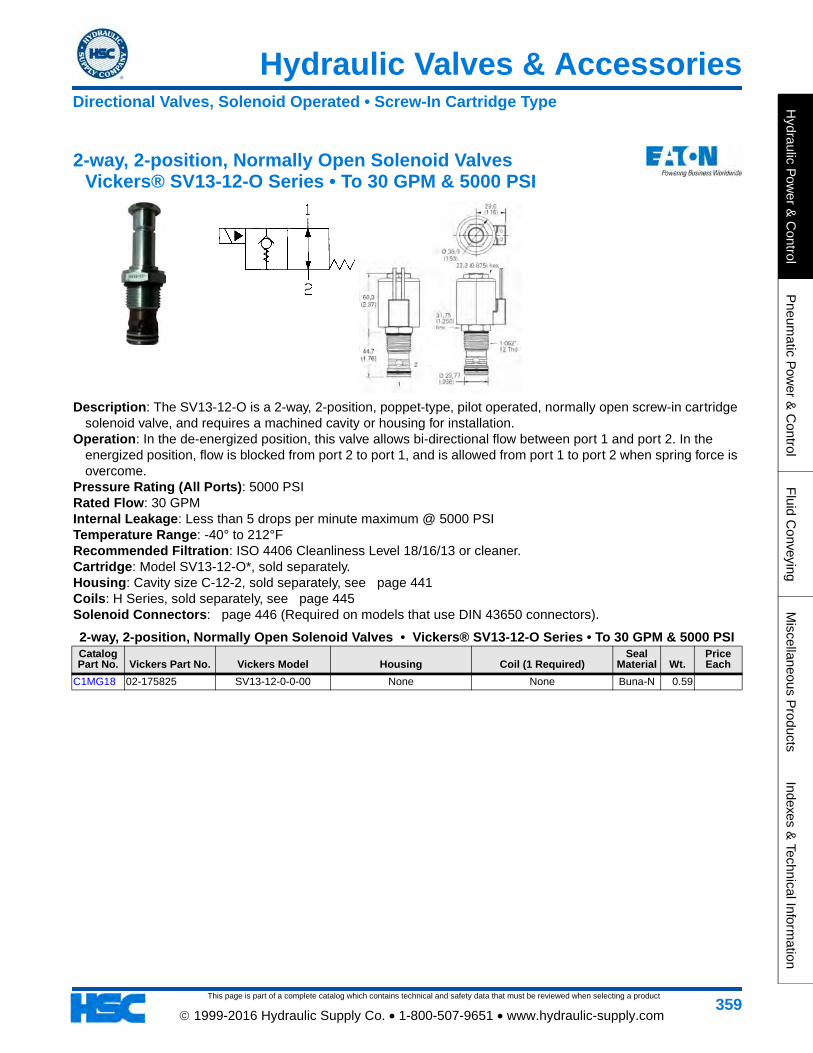
Hydraulic Valves & Accessories
This page is part of a complete catalog which contains technical and safety data that must be reviewed when selecting a product
Hydraulic P
ower &
Control
Pneum
atic Pow
er & C
ontrolF
luid Conveying
Miscellaneous P
roductsIndexes &
Technical Information
359 1999-2016 Hydraulic Supply Co. • 1-800-507-9651 • www.hydraulic-supply.com
2-way, 2-position, Normally Open Solenoid Valves Vickers® SV13-12-O Series • To 30 GPM & 5000 PSI
Description: The SV13-12-O is a 2-way, 2-position, poppet-type, pilot operated, normally open screw-in cartridge solenoid valve, and requires a machined cavity or housing for installation.
Operation: In the de-energized position, this valve allows bi-directional flow between port 1 and port 2. In the energized position, flow is blocked from port 2 to port 1, and is allowed from port 1 to port 2 when spring force is overcome.
Pressure Rating (All Ports): 5000 PSI Rated Flow: 30 GPM Internal Leakage: Less than 5 drops per minute maximum @ 5000 PSI Temperature Range: -40° to 212°F Recommended Filtration: ISO 4406 Cleanliness Level 18/16/13 or cleaner. Cartridge: Model SV13-12-O*, sold separately. Housing: Cavity size C-12-2, sold separately, see page 441Coils: H Series, sold separately, see page 445Solenoid Connectors: page 446 (Required on models that use DIN 43650 connectors).
2-way, 2-position, Normally Open Solenoid Valves • Vickers® SV13-12-O Series • To 30 GPM & 5000 PSICatalog Part No. Vickers Part No. Vickers Model Housing Coil (1 Required)
Seal Material Wt.
Price Each
C1MG18 02-175825 SV13-12-0-0-00 None None Buna-N 0.59
Directional Valves, Solenoid Operated • Screw-In Cartridge Type

This page is part of a complete catalog which contains technical and safety data that must be reviewed when selecting a product
Hydraulic Valves & Accessories
Hyd
raul
ic P
ower
& C
ontr
olP
neum
atic
Pow
er &
Con
trol
Flu
id C
onve
ying
Mis
cella
neou
s P
rodu
cts
Inde
xes
& T
echn
ical
Info
rmat
ion
360 1999-2016 Hydraulic Supply Co. • 1-800-507-9651 • www.hydraulic-supply.com
2-way, 2-position, Normally Open Solenoid Valves Vickers® SV3-16-O Series • To 35 GPM & 3000 PSI
Description: The SV3-16-O is a 2-way, 2-position, poppet-type, pilot operated, normally open screw-in cartridge solenoid valve, and requires a machined cavity or housing for installation.
Operation: In the de-energized position, this valve allows bi-directional flow between port 1 and port 2. In the energized position, flow is blocked from port 2 to port 1, and is allowed from port 1 to port 2 when spring force is overcome.
Pressure Rating (All Ports): 3000 PSI. Rated Flow: 35 GPM. Internal Leakage: Port 2 to Port 1: Less than 5 drops per minute maximum @ 3000 PSI with valve energized. Note: Performance data is typical with fluid at 105 SSU and 120°F. Temperature Range: -40°F to 248°F (Extreme Limits). Recommended Filtration: ISO 4406 Cleanliness Level 18/16/13 or cleaner. Cartridge: Model SV3-16-O*, sold separately. Housing: Cavity size C-16-2, sold separately, see page 441Solenoid Connectors: page 446 (Required on models that use DIN 43650 connectors). Coil: "J" Series 20 Watt, sold separately, see page 445
2-way, 2-position, Normally Open Solenoid Valves • Vickers® SV3-16-O Series • To 35 GPM & 3000 PSICatalog Part No.
Vickers Part No. Vickers Model
Manual Override Option Housing Coil (1 Required)
Seal Material Wt.
Price Each
•C1BT26 565544 SV3-16-O-0-00 No None None Buna-N 0.74
Housing Types: Aluminum STD (Standard light-duty aluminum 3000 psi maximum). Aluminum FR (Fatigue-rated aluminum 3000 psi maximum). Steel (Fatigue-rated Steel 5000 psi maximum).
Directional Valves, Solenoid Operated • Screw-In Cartridge Type

Hydraulic Valves & Accessories
This page is part of a complete catalog which contains technical and safety data that must be reviewed when selecting a product
Hydraulic P
ower &
Control
Pneum
atic Pow
er & C
ontrolF
luid Conveying
Miscellaneous P
roductsIndexes &
Technical Information
361 1999-2016 Hydraulic Supply Co. • 1-800-507-9651 • www.hydraulic-supply.com
2-way, 2-position, Normally Open Solenoid Valves Vickers® SV13-16-O Series • To 35 GPM & 5000 PSI
Description: The SV13-16-O is a 2-way, 2-position, poppet-type, pilot operated, normally open screw-in cartridge solenoid valve, and requires a machined cavity or housing for installation.
Operation: In the de-energized position, this valve allows bi-directional flow between port 1 and port 2. In the energized position, flow is blocked from port 2 to port 1, and is allowed from port 1 to port 2 when spring force is overcome.
Pressure Rating (All Ports): 5000 PSI Rated Flow: 35 GPM Internal Leakage: Less than 5 drops per minute maximum @ 5000 PSI. Temperature Range: -40° to 212°F Recommended Filtration: ISO 4406 Cleanliness Level 18/16/13 or cleaner. Cartridge: Model SV13-16-O*, sold separately. Housing: Cavity size C-16-2, sold separately, see page 441Coils: page 445H Series, sold separately, see Solenoid Connectors: page 446 (Required on models that use DIN 43650 connectors).
2-way, 2-position, Normally Open Solenoid Valves • Vickers® SV13-16-O Series • To 35 GPM & 5000 PSICatalog Part No. Vickers Part No. Vickers Model Housing Coil (1 Required)
Seal Material Wt.
Price Each
C1MG16 02-175821 SV13-16-0-0-00 None None Buna-N 0.95
Directional Valves, Solenoid Operated • Screw-In Cartridge Type

This page is part of a complete catalog which contains technical and safety data that must be reviewed when selecting a product
Hydraulic Valves & Accessories
Hyd
raul
ic P
ower
& C
ontr
olP
neum
atic
Pow
er &
Con
trol
Flu
id C
onve
ying
Mis
cella
neou
s P
rodu
cts
Inde
xes
& T
echn
ical
Info
rmat
ion
362 1999-2016 Hydraulic Supply Co. • 1-800-507-9651 • www.hydraulic-supply.com
2-way, 2-position, Normally Open Solenoid Valves Vickers® SV3-20-O Series • To 60 GPM & 3000 PSI
Description: The SV3-20-O is a 2-way, 2-position, poppet-type, pilot operated, normally open screw-in cartridge solenoid valve, and requires a machined cavity or housing for installation.
Operation: In the de-energized position, this valve allows bi-directional flow between port 1 and port 2. In the energized position, flow is blocked from port 2 to port 1, and is allowed from port 1 to port 2 when spring force is overcome.
Pressure Rating (All Ports): 3000 PSI. Rated Flow: 60 GPM. Internal Leakage: Port 2 to Port 1: Less than 5 drops per minute maximum @ 3000 PSI with valve energized. Note: Performance data is typical with fluid at 105 SSU and 120°F. Temperature Range: -40°F to 248°F (Extreme Limits). Recommended Filtration: ISO 4406 Cleanliness Level 18/16/13 or cleaner. Cartridge: Model SV3-20-O*, sold separately. Housing: Cavity size C-20-2, sold separately, see page 441Solenoid Connectors: page 446 (Required on models that use DIN 43650 connectors). Coil: "J" Series 20 Watt, sold separately, see page 445
2-way, 2-position, Normally Open Solenoid Valves • Vickers® SV3-20-O Series • To 60 GPM & 3000 PSICatalog Part No.
Vickers Part No. Vickers Model
Manual Override Option Housing Coil (1 Required)
Seal Material Wt.
Price Each
C1BT27 565545 SV3-20-O-0-00 No None None Buna-N 1.25
Housing Types: Aluminum STD (Standard light-duty aluminum 3000 psi maximum). Aluminum FR (Fatigue-rated aluminum 3000 psi maximum). Steel (Fatigue-rated Steel 5000 psi maximum).
Directional Valves, Solenoid Operated • Screw-In Cartridge Type
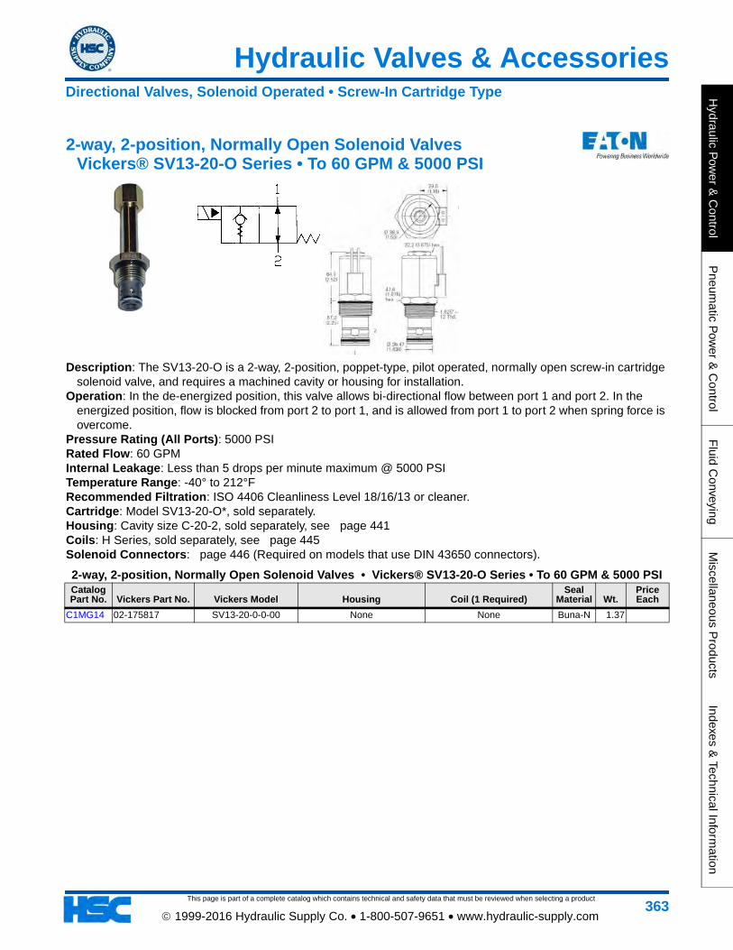
Hydraulic Valves & Accessories
This page is part of a complete catalog which contains technical and safety data that must be reviewed when selecting a product
Hydraulic P
ower &
Control
Pneum
atic Pow
er & C
ontrolF
luid Conveying
Miscellaneous P
roductsIndexes &
Technical Information
363 1999-2016 Hydraulic Supply Co. • 1-800-507-9651 • www.hydraulic-supply.com
2-way, 2-position, Normally Open Solenoid Valves Vickers® SV13-20-O Series • To 60 GPM & 5000 PSI
Description: The SV13-20-O is a 2-way, 2-position, poppet-type, pilot operated, normally open screw-in cartridge solenoid valve, and requires a machined cavity or housing for installation.
Operation: In the de-energized position, this valve allows bi-directional flow between port 1 and port 2. In the energized position, flow is blocked from port 2 to port 1, and is allowed from port 1 to port 2 when spring force is overcome.
Pressure Rating (All Ports): 5000 PSI Rated Flow: 60 GPM Internal Leakage: Less than 5 drops per minute maximum @ 5000 PSI Temperature Range: -40° to 212°F Recommended Filtration: ISO 4406 Cleanliness Level 18/16/13 or cleaner. Cartridge: Model SV13-20-O*, sold separately. Housing: Cavity size C-20-2, sold separately, see page 441Coils: H Series, sold separately, see page 445Solenoid Connectors: page 446 (Required on models that use DIN 43650 connectors).
2-way, 2-position, Normally Open Solenoid Valves • Vickers® SV13-20-O Series • To 60 GPM & 5000 PSICatalog Part No. Vickers Part No. Vickers Model Housing Coil (1 Required)
Seal Material Wt.
Price Each
C1MG14 02-175817 SV13-20-0-0-00 None None Buna-N 1.37
Directional Valves, Solenoid Operated • Screw-In Cartridge Type

This page is part of a complete catalog which contains technical and safety data that must be reviewed when selecting a product
Hydraulic Valves & Accessories
Hyd
raul
ic P
ower
& C
ontr
olP
neum
atic
Pow
er &
Con
trol
Flu
id C
onve
ying
Mis
cella
neou
s P
rodu
cts
Inde
xes
& T
echn
ical
Info
rmat
ion
364 1999-2016 Hydraulic Supply Co. • 1-800-507-9651 • www.hydraulic-supply.com
3-way, 2-position Solenoid Valves Vickers® SV1-8-3 Series • To 3 GPM & 3000 PSI
Description: The SV1-8-3 is a 3-way, 2-position, spool-type, direct acting screw-in cartridge solenoid valve, and requires a machined cavity or housing for installation. This valve can be used in applications requiring separate pressure and tank lines, such as a single acting cylinder.
Operation: In the de-energized position, this valve allows flow from port 2 to port 1 while port 3 is blocked. In the energized position, flow is allowed from port 1 to port 3 while port 2 is blocked.
Pressure Rating: 3000 PSI all ports. Rated Flow: 3 GPM. Internal Leakage: 5 in³ per minute maximum @ 3000 PSI. Note: Performance data is typical with fluid at 105 SSU and 120°F. Temperature Range: -40°F to 248°F (Extreme Limits). Recommended Filtration: ISO 4406 Cleanliness Level 18/16/13 or cleaner. Cartridge: Model SV1-8-3*, sold separately. Housing: Cavity size C-8-3, sold separately, see page 442Solenoid Connectors: page 446 (Required on models that use DIN 43650 connectors). Seal Kit: 02-160755 (Buna-N), 02-160756 (Viton®). Coil: "S" Series 16 Watt, sold separately, see page 445
3-way, 2-position Solenoid Valves • Vickers® SV1-8-3 Series • To 3 GPM & 3000 PSICatalog Part No.
Vickers Part No. Vickers Model
Manual Override Option Housing Coil (1 Required)
Seal Material Wt.
Price Each
•C1HL36 02-160771 SV1-8-3-0-00 No None None Buna-N 0.24
Housing Types: Aluminum STD (Standard light-duty aluminum 3000 psi maximum). Aluminum FR (Fatigue-rated aluminum 3000 psi maximum). Steel (Fatigue-rated Steel 5000 psi maximum).
Directional Valves, Solenoid Operated • Screw-In Cartridge Type

Hydraulic Valves & Accessories
This page is part of a complete catalog which contains technical and safety data that must be reviewed when selecting a product
Hydraulic P
ower &
Control
Pneum
atic Pow
er & C
ontrolF
luid Conveying
Miscellaneous P
roductsIndexes &
Technical Information
365 1999-2016 Hydraulic Supply Co. • 1-800-507-9651 • www.hydraulic-supply.com
3-way, 2-position Solenoid Valves Vickers® SV4-8-3 Series • To 4 GPM & 3000 PSI
Description: The SV4-8-3 is a 3-way, 2-position, spool-type, direct acting screw-in cartridge solenoid valve, and requires a machined cavity or housing for installation.
Operation: In the de-energized position, this valve allows flow from port 2 to port 1 while port 3 is blocked. In the energized position, flow is allowed from port 2 to port 3 while port 1 is blocked. Pressure on port 1 should not exceed 300 PSI.
Pressure Rating: 3000 PSI port 2 and port 3. 300 PSI port 1. Rated Flow: 4 GPM. Internal Leakage: 5 in³ per minute maximum @ 3000 PSI. Note: Performance data is typical with fluid at 105 SSU and 120°F. Temperature Range: -40°F to 248°F (Extreme Limits). Recommended Filtration: ISO 4406 Cleanliness Level 18/16/13 or cleaner. Cartridge: Model SV4-8-3*, sold separately. Housing: Cavity size C-8-3, sold separately, see page 442Solenoid Connectors: page 446 (Required on models that use DIN 43650 connectors). Coil: "S" Series 16 Watt, sold separately, see page 445
3-way, 2-position Solenoid Valves • Vickers® SV4-8-3 Series • To 4 GPM & 3000 PSICatalog Part No.
Vickers Part No. Vickers Model
Manual Override Option Housing Coil (1 Required)
Seal Material Wt.
Price Each
C1FV36 02-198050 SV4-8-3-0-24BNS No None
24VDC with Deutsch connector and with
arc suppression diode
Buna-N 0.74
Housing Types: Aluminum STD (Standard light-duty aluminum 3000 psi maximum). Aluminum FR (Fatigue-rated aluminum 3000 psi maximum). Steel (Fatigue-rated Steel 5000 psi maximum).
Directional Valves, Solenoid Operated • Screw-In Cartridge Type
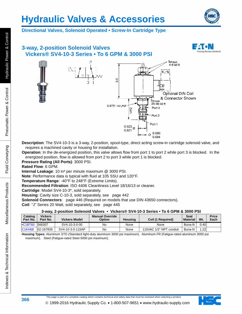
This page is part of a complete catalog which contains technical and safety data that must be reviewed when selecting a product
Hydraulic Valves & Accessories
Hyd
raul
ic P
ower
& C
ontr
olP
neum
atic
Pow
er &
Con
trol
Flu
id C
onve
ying
Mis
cella
neou
s P
rodu
cts
Inde
xes
& T
echn
ical
Info
rmat
ion
366 1999-2016 Hydraulic Supply Co. • 1-800-507-9651 • www.hydraulic-supply.com
3-way, 2-position Solenoid Valves Vickers® SV4-10-3 Series • To 6 GPM & 3000 PSI
Description: The SV4-10-3 is a 3-way, 2-position, spool-type, direct acting screw-in cartridge solenoid valve, and requires a machined cavity or housing for installation.
Operation: In the de-energized position, this valve allows flow from port 1 to port 2 while port 3 is blocked. In the energized position, flow is allowed from port 2 to port 3 while port 1 is blocked.
Pressure Rating (All Ports): 3000 PSI. Rated Flow: 6 GPM. Internal Leakage: 10 in³ per minute maximum @ 3000 PSI. Note: Performance data is typical with fluid at 105 SSU and 120°F. Temperature Range: -40°F to 248°F (Extreme Limits). Recommended Filtration: ISO 4406 Cleanliness Level 18/16/13 or cleaner. Cartridge: Model SV4-10-3*, sold separately. Housing: Cavity size C-10-3, sold separately, see page 442Solenoid Connectors: page 446 (Required on models that use DIN 43650 connectors). Coil: "J" Series 20 Watt, sold separately, see page 445
3-way, 2-position Solenoid Valves • Vickers® SV4-10-3 Series • To 6 GPM & 3000 PSICatalog Part No.
Vickers Part No. Vickers Model
Manual Override Option Housing Coil (1 Required)
Seal Material Wt.
Price Each
•C1BT60 566307 SV4-10-3-0-00 No None None Buna-N 0.40
C1KH68 02-167839 SV4-10-3-0-115AP No None 115VAC 1/2" NPT conduit Buna-N 1.22
Housing Types: Aluminum STD (Standard light-duty aluminum 3000 psi maximum). Aluminum FR (Fatigue-rated aluminum 3000 psi maximum). Steel (Fatigue-rated Steel 5000 psi maximum).
Directional Valves, Solenoid Operated • Screw-In Cartridge Type
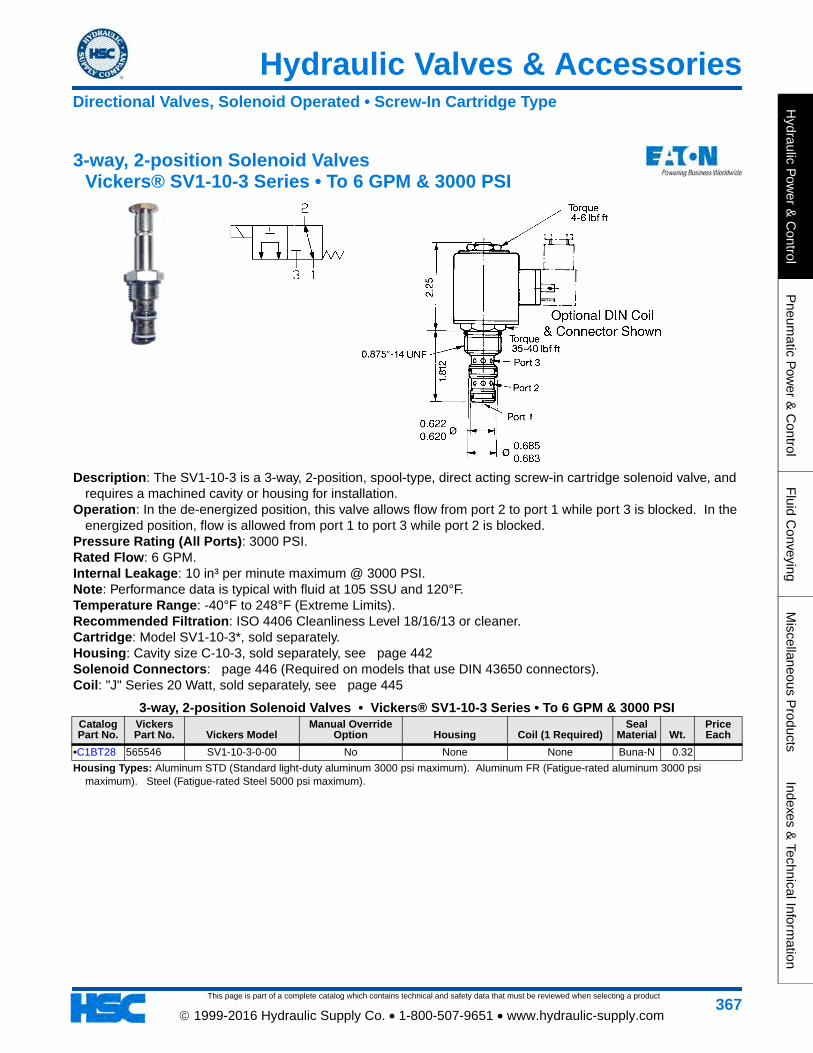
Hydraulic Valves & Accessories
This page is part of a complete catalog which contains technical and safety data that must be reviewed when selecting a product
Hydraulic P
ower &
Control
Pneum
atic Pow
er & C
ontrolF
luid Conveying
Miscellaneous P
roductsIndexes &
Technical Information
367 1999-2016 Hydraulic Supply Co. • 1-800-507-9651 • www.hydraulic-supply.com
3-way, 2-position Solenoid Valves Vickers® SV1-10-3 Series • To 6 GPM & 3000 PSI
Description: The SV1-10-3 is a 3-way, 2-position, spool-type, direct acting screw-in cartridge solenoid valve, and requires a machined cavity or housing for installation.
Operation: In the de-energized position, this valve allows flow from port 2 to port 1 while port 3 is blocked. In the energized position, flow is allowed from port 1 to port 3 while port 2 is blocked.
Pressure Rating (All Ports): 3000 PSI. Rated Flow: 6 GPM. Internal Leakage: 10 in³ per minute maximum @ 3000 PSI. Note: Performance data is typical with fluid at 105 SSU and 120°F. Temperature Range: -40°F to 248°F (Extreme Limits). Recommended Filtration: ISO 4406 Cleanliness Level 18/16/13 or cleaner. Cartridge: Model SV1-10-3*, sold separately. Housing: Cavity size C-10-3, sold separately, see page 442Solenoid Connectors: page 446 (Required on models that use DIN 43650 connectors). Coil: "J" Series 20 Watt, sold separately, see page 445
3-way, 2-position Solenoid Valves • Vickers® SV1-10-3 Series • To 6 GPM & 3000 PSICatalog Part No.
Vickers Part No. Vickers Model
Manual Override Option Housing Coil (1 Required)
Seal Material Wt.
Price Each
•C1BT28 565546 SV1-10-3-0-00 No None None Buna-N 0.32
Housing Types: Aluminum STD (Standard light-duty aluminum 3000 psi maximum). Aluminum FR (Fatigue-rated aluminum 3000 psi maximum). Steel (Fatigue-rated Steel 5000 psi maximum).
Directional Valves, Solenoid Operated • Screw-In Cartridge Type

This page is part of a complete catalog which contains technical and safety data that must be reviewed when selecting a product
Hydraulic Valves & Accessories
Hyd
raul
ic P
ower
& C
ontr
olP
neum
atic
Pow
er &
Con
trol
Flu
id C
onve
ying
Mis
cella
neou
s P
rodu
cts
Inde
xes
& T
echn
ical
Info
rmat
ion
368 1999-2016 Hydraulic Supply Co. • 1-800-507-9651 • www.hydraulic-supply.com
4-way, 2-position Solenoid Valves Vickers® SV1-10-4 Series • To 6 GPM & 3000 PSI
Description: The SV1-10-4 is a 4-way, 2-position, spool-type, direct acting screw-in cartridge solenoid valve, and requires a machined cavity or housing for installation.
Operation: In the de-energized position, this valve allows flow from port 2 to port 3 and from port 4 to port 1. In the energized position, flow is allowed from port 3 to port 4 and from port 2 to port 1.
Pressure Rating (All Ports): 3000 PSI. Rated Flow: 6 GPM. Internal Leakage: 10 in³ per minute maximum @ 3000 PSI. Note: Performance data is typical with fluid at 105 SSU and 120°F. Temperature Range: -40°F to 248°F (Extreme Limits). Recommended Filtration: ISO 4406 Cleanliness Level 18/16/13 or cleaner. Cartridge: Model SV1-10-4*, sold separately. Housing: Cavity size C-10-4, sold separately, see page 443Solenoid Connectors: page 446 (Required on models that use DIN 43650 connectors). Coil: "J" Series 20 Watt, sold separately, see page 445
4-way, 2-position Solenoid Valves • Vickers® SV1-10-4 Series • To 6 GPM & 3000 PSICatalog Part No.
Vickers Part No. Vickers Model
Manual Override Option Housing Coil (1 Required)
Seal Material Wt.
Price Each
•C1BT29 565547 SV1-10-4-0-00 No None None Buna-N 0.36
Housing Types: Aluminum STD (Standard light-duty aluminum 3000 psi maximum). Aluminum FR (Fatigue-rated aluminum 3000 psi maximum). Steel (Fatigue-rated Steel 5000 psi maximum).
Directional Valves, Solenoid Operated • Screw-In Cartridge Type

Hydraulic Valves & Accessories
This page is part of a complete catalog which contains technical and safety data that must be reviewed when selecting a product
Hydraulic P
ower &
Control
Pneum
atic Pow
er & C
ontrolF
luid Conveying
Miscellaneous P
roductsIndexes &
Technical Information
369 1999-2016 Hydraulic Supply Co. • 1-800-507-9651 • www.hydraulic-supply.com
4-way, 3-position Solenoid Valves Vickers® SV9-8 Series • To 3.5 GPM & 3000 PSI
Description: The SV9-10 is a 4-way, 3-position, spool-type, direct acting screw-in cartridge solenoid valve, and requires a machined cavity or housing for installation.
Operation: Closed Center Valves: In the de-energized position, all ports are blocked. When solenoid 1 is energized, flow is directed from port 3 to port 2 and from port 4 to port 1. When solenoid 2 is energized, flow is directed from port 3 to port 4 and from port 2 to port 1. Tandem Center Valves: In the de-energized position, this valve allows flow from 3 to port 1 and blocks ports 2 and 4. When solenoid 1 is energized, flow is directed from port 3 to port 2 and from port 4 to port 1. When solenoid 2 is energized, flow is directed from port 3 to port 4 and from port 2 to port 1.
Pressure Rating (All Ports): 3000 PSI. Rated Flow: Tandem Center models 3 GPM, Others 3.5 GPM. Internal Leakage: 10 in³ per minute maximum @ 3000 PSI. Note: Performance data is typical with fluid at 105 SSU and 120°F. Temperature Range: -40°F to 248°F (Extreme Limits). Recommended Filtration: ISO 4406 Cleanliness Level 18/16/13 or cleaner. Cartridge: Model SV9-8*, sold separately. Housing: Cavity size C-8-4, sold separately. Aluminum NFPA fatigue rated models: 02-160749 SAE-6 Ports,
02-160750 SAE-8 Ports. See page 443Solenoid Connectors: page 446 (Required on models that use DIN 43650 connectors). Coils: "P" Series 20 Watt, sold separately, see page 445
4-way, 3-position Solenoid Valves • Vickers® SV9-8 Series • To 3.5 GPM & 3000 PSICatalog Part No.
Vickers Part No. Vickers Model Circuit Type Housing Coils (2 Required)
Seal Material Wt.
Price Each
C1HW91 02-198685 VICK SV98NF00000000000000 P Blocked, A&B Open None None Buna-N 0.50
Note: (1ea) 02-186730 Spacer is REQUIRED to assemble a valve. (Select from table below).
Parts for Vickers® SV9-8 Solenoid Valve CartridgesCatalog Part No. Part Number Description Wt.
Price Each
C1HW46 02-186730 Spacer (To be inserted between the coils - REQUIRED) 0.06
Directional Valves, Solenoid Operated • Screw-In Cartridge Type

This page is part of a complete catalog which contains technical and safety data that must be reviewed when selecting a product
Hydraulic Valves & Accessories
Hyd
raul
ic P
ower
& C
ontr
olP
neum
atic
Pow
er &
Con
trol
Flu
id C
onve
ying
Mis
cella
neou
s P
rodu
cts
Inde
xes
& T
echn
ical
Info
rmat
ion
370 1999-2016 Hydraulic Supply Co. • 1-800-507-9651 • www.hydraulic-supply.com
4-way, 3-position Solenoid Valves Vickers® SV9-10 Series • To 6 GPM & 3000 PSI
Description: The SV9-10 is a 4-way, 3-position, spool-type, direct acting screw-in cartridge solenoid valve, and requires a machined cavity or housing for installation.
Operation: Closed Center Valves: In the de-energized position, all ports are blocked. When solenoid 1 is energized, flow is directed from port 3 to port 2 and from port 4 to port 1. When solenoid 2 is energized, flow is directed from port 3 to port 4 and from port 2 to port 1. Tandem Center Valves: In the de-energized position, this valve allows flow from 3 to port 1 and blocks ports 2 and 4. When solenoid 1 is energized, flow is directed from port 3 to port 2 and from port 4 to port 1. When solenoid 2 is energized, flow is directed from port 3 to port 4 and from port 2 to port 1.
Pressure Rating (All Ports): 3000 PSI. Rated Flow: Tandem Center models 5 GPM, Others 6 GPM. Internal Leakage: 15 in³ per minute maximum @ 3000 PSI. Note: Performance data is typical with fluid at 105 SSU and 120°F. Temperature Range: -40°F to 248°F (Extreme Limits). Recommended Filtration: ISO 4406 Cleanliness Level 18/16/13 or cleaner. Cartridge: Model SV9-10*, sold separately. Housing: Cavity size C-10-4, sold separately, see page 443Solenoid Connectors: page 446 (Required on models that use DIN 43650 connectors). Coils: "J" Series 20 Watt, sold separately, see page 445
4-way, 3-position Solenoid Valves • Vickers® SV9-10 Series • To 6 GPM & 3000 PSICatalog Part No.
Vickers Part No. Vickers Model Circuit Type Housing Coils (2 Required)
Seal Material Wt.
Price Each
•C1KY86 02-199325 SV910NA00000000000000A Tandem Center None None Buna-N 0.53
C1KX60 02-199329 SV910NF00000000000000A P Blocked, A&B Open to Tank None None Buna-N 0.53
Note: (1ea) 02-179226 Spacer is REQUIRED to assemble a valve (Select from table below).
Parts for Vickers® SV9-10 Solenoid Valve CartridgesCatalog Part No. Part Number Description Wt.
Price Each
•C1AD39 02-179226 Spacer (To be inserted between the coils - REQUIRED) 0.06
Directional Valves, Solenoid Operated • Screw-In Cartridge Type

Hydraulic Valves & Accessories
This page is part of a complete catalog which contains technical and safety data that must be reviewed when selecting a product
Hydraulic P
ower &
Control
Pneum
atic Pow
er & C
ontrolF
luid Conveying
Miscellaneous P
roductsIndexes &
Technical Information
371 1999-2016 Hydraulic Supply Co. • 1-800-507-9651 • www.hydraulic-supply.com
4-way, 3-position Solenoid Valves Eaton SV9A-10 Series • To 8.9 GPM & 3000 PSI
Description: This is a 4 way 3 position, direct acting, spool type solenoid valve and requires a machined cavity or housing for installation. This valve is ideal for small flow applications where an actuator needs to be moved in both directions. Hardened, ground and honed working parts to limit leakage. IP69K Tough coil compatibility. Continuously rated. Compact design with low pressure drop. Rated pressure on all ports.
Operation: Closed Center: In the de-energized position, all ports are blocked. When solenoid 1 is energized, flow is directed from port 3 to port 2 and from port 4 to port 1. When solenoid 2 is energized, flow is directed from port 3 to port 4 and from port 2 to port 1. Tandem Center: In the de-energized position, this valve allows flow from 3 to port 1 and blocks ports 2 and 4. When solenoid 1 is energized, flow is directed from port 3 to port 2 and from port 4 to port 1. When solenoid 2 is energized, flow is directed from port 3 to port 4 and from port 2 to port 1. Open Center: In the de-energized position all ports are open. When solenoid 'A' is energized flow is allowed from port 3 to port 4 and port 2 to port 1. When solenoid 'B' is energized flow is allowed from port 3 to port 2 and from port 4 to port 1. P Blocked, A&B Open to Tank: In the de-energized (center) position, port 1, port 2, and port 4 are open to each other while port 3 is blocked. When solenoid A is energized, flow is directed from port 3 to port 4 and from port 2 to port 1. When solenoid B is energized, flow is directed from port 3 to port 2 and from port 4 to port 1.
Pressure Rating (All Ports): 3000 PSI Rated Flow: See chart below Internal Leakage: Less than 7.3 in³/min past each land 3000 PSI differential Note: Performance data is typical with fluid at 150 SSU and 120°F. Temperature Range: -22° to +248°F Recommended Filtration: BS5540/4 Class 18/13 (25 micron or better) Cartridge: Model SV9A-10* sold separately. Housing: Cavity size C-10-4, sold separately, see page 443Solenoid Connectors: Required on models with DIN 43650 connectors. See page 446Coils: "L" Series, 30W. Sold separately, see page 445
4-way, 3-position Solenoid Valves • Eaton SV9A-10 Series • To 8.9 GPM & 3000 PSI
Catalog Part No.
Eaton Part No. Eaton Model Circuit Type Housing
Coils (2 Required)
Seal Material
Rated Flow
(GPM) Wt.Price Each
C1LX26 403AA01054A
SV9A-10-N-B-0-0-00 Open Center None None Buna-N 8.9 0.55
SV9A-10-N-F-0-0-00
P Blocked, A&B Open to Tank
Not Included Not Included Buna-N 6.5 0.55
Directional Valves, Solenoid Operated • Screw-In Cartridge Type

This page is part of a complete catalog which contains technical and safety data that must be reviewed when selecting a product
Hydraulic Valves & Accessories
Hyd
raul
ic P
ower
& C
ontr
olP
neum
atic
Pow
er &
Con
trol
Flu
id C
onve
ying
Mis
cella
neou
s P
rodu
cts
Inde
xes
& T
echn
ical
Info
rmat
ion
372 1999-2016 Hydraulic Supply Co. • 1-800-507-9651 • www.hydraulic-supply.com
Vickers® DG4V-3S (Standard Performance) • Flows to 10.5 GPM DG4V-3 (High Performance) • Flows to 21 GPM
Features: High reliability. High pressure & flow capability. Low pressure drops. Viton® seals. Scratch-proof manual override. Coil change with valve in place. ISO 4401 Size 03, NFPA D03 port interface.Maximum Operating Pressure: 5075 psi. (CAUTION: Pressures over 3000 PSI require steel subplate or manifold). (See tables for port T pressure rating).
Maximum Flow Rates: Dependent on spool/spring combination and coil.Operating Fluid Temperature Range: -4°F to 158°F (Mineral oil), +50°F to 129°F (water based fluids).Ambient Temperature Range: DG4V-3S: 4°F to 149°F (Dual freq. Coil @110% voltage). DG4V-3: -4°F to 122°F (Dual freq. coil @107% voltage), -4°F to 104°F (Dual freq. coil @ 110% voltage).Mounting Considerations: Detented models should mount with longitudinal axis horizontal. Other models may
be mounted in any position.Service Parts: page 375Technical Information: page 673Note: These valves are available in a wide variety of configurations not shown in this catalog. Contact us for
detailed information.Size D03 Subplates & Manifolds: page 450Solenoid Connectors: page 446(Required on models that use DIN 43650 connectors).Mounting Bolts: Standard mounting bolts are 4ea 10-24 x 1-1/4 Grade 8 socket head capscrews (Vickers Bolt Kit
590716), torqued to 44-62 lb.in. with threads lubricated. See Bolt Kits on page 440
4-way, 3-position, Spring Centered Spool / Spring Code 2C
Transient conditions during shift: P to A: All blocked. P to B: All blocked. Maximum Flow Rates @ 3000 PSI: Standard Performance: AC Coils 10 GPM, DC Coils 8 GPM. High Performance: AC Coils 16 GPM, DC Coils 21 GPM.
4-way, 3-position, Spring Centered • Spool / Spring Code 2C
Catalog Part No.
Vickers Part No. Vickers Model Type Coil Rating Coil Type
Port T Rating (psi)
Optional Features Wt.
Price Each
C1AC46 02-109686 DG4V-3S-2C-M-U-B5-60 STD 110VAC50Hz 120VAC60Hz DIN 43650 1500 4.25
•C1AC42 02-109575 DG4V-3S-2C-M-FW-B5-60 STD 110VAC50Hz 120VAC60Hz
Lead wires Conduit box 1500 4.25
C1JS96 02-109026 DG4V-3S-2C-M-U-D5-60 STD 220VAC50Hz 240VAC60Hz DIN 43650 1500 4.05
•C1AC37 02-109055 DG4V-3S-2C-M-U-G5-60 STD 12VDC DIN 43650 1500 4.70
C1LA85 02-109943 DG4V-3S-2C-H-M-U-G5-60 STD 12VDC DIN 43650 1500 Water-resistant override
•C1AC49 02-109826 DG4V-3S-2C-M-FW-G5-60 STD 12VDC Lead wires Conduit box 1500 4.83
•C1AC31 02-109025 DG4V-3S-2C-M-U-H5-60 STD 24VDC DIN 43650 1500 4.68
C1KD96 859161 DG4V-3-2C-M-U-B6-60 HP 110VAC50Hz 120VAC60Hz DIN 43650 3000 4.13
C1KD98 859172 DG4V-3-2C-M-U-D6-60 HP 220VAC50Hz 240VAC60Hz DIN 43650 3000 4.00
C1BS80 529760 DG4V-3-2C-M-U-H7-60 HP 24VDC DIN 43650 3000 4.79
Directional Valves, Solenoid Operated • NFPA Size D03 • ISO 4401 Size 03Vickers DG4V-3 & DG4V-3S Series

This page is part of a complete catalog which contains technical and safety data that must be reviewed when selecting a product
Hydraulic Valves & Accessories
Hydraulic P
ower &
Control
Pneum
atic Pow
er & C
ontrolF
luid Conveying
Miscellaneous P
roductsIndexes &
Technical Information
373 1999-2016 Hydraulic Supply Co. • 1-800-507-9651 • www.hydraulic-supply.com
4-way, 3-position, Spring Centered Spool / Spring Code 8C
Transient conditions during shift: P to A: P & A restricted opening to T, B blocked. P to B: P & B restricted opening to T, A blocked. Maximum Flow Rates @ 3000 PSI: Standard Performance: AC Coils 3 GPM, DC Coils 2.5 GPM. High Performance: AC Coils 9 GPM, DC Coils 12 GPM.
4-way, 3-position, Spring Centered • Spool / Spring Code 8C
Catalog Part No.
Vickers Part No. Vickers Model Type Coil Rating Coil Type
Port T Rating (psi)
Optional Features Wt.
Price Each
C1AC96 02-145188 DG4V-3S-8C-VM-U-B5-61 STD 110VAC50Hz 120VAC60Hz DIN 43650 1500 3.00
•C1AC93 02-145150 DG4V-3S-8C-VM-FW-B5-61 STD 110VAC50Hz 120VAC60Hz
Lead wires Conduit box 1500 4.25
C1JP87 02-144939 DG4V-3S-8C-VM-U-D5-61 STD 220VAC50Hz 240VAC60Hz DIN 43650 1500 4.05
•C1AC97 02-145190 DG4V-3S-8C-VM-U-G5-61 STD 12VDC DIN 43650 1500 4.68
•C1AC95 02-145182 DG4V-3S-8C-VM-FW-G5-61 STD 12VDC Lead wires Conduit box 1500 5.00
•C1AC98 02-145192 DG4V-3S-8C-VM-U-H5-61 STD 24VDC DIN 43650 1500 5.00
•C1AC94 02-145158 DG4V-3-8C-VM-FW-B6-61 HP 110VAC50Hz 120VAC60Hz
Lead wires Conduit box 3000 4.20
4-way, 3-position, Spring Centered Spool / Spring Code 6C
Transient conditions during shift: P to A: P & A blocked, B open to T. P to B: P & B blocked, A open to T. Maximum Flow Rates @ 3000 PSI: Standard Performance: AC Coils 5 GPM, DC Coils 3.5 GPM. High Performance: AC Coils 5 GPM, DC Coils 9 GPM.
4-way, 3-position, Spring Centered • Spool / Spring Code 6C
Catalog Part No.
Vickers Part No. Vickers Model Type Coil Rating Coil Type
Port T Rating (psi)
Optional Features Wt.
Price Each
C1AC48 02-109824 DG4V-3S-6C-M-U-B5-60 STD 110VAC50Hz 120VAC60Hz DIN 43650 1500 4.02
•C1AC41 02-109573 DG4V-3S-6C-M-FW-B5-60 STD 110VAC50Hz 120VAC60Hz
Lead wires Conduit box 1500 4.25
•C1AC43 02-109628 DG4V-3S-6C-M-FW-G5-60 STD 12VDC Lead wires Conduit box 1500 4.80
•C1AC35 02-109047 DG4V-3S-6C-M-U-H5-60 STD 24VDC DIN 43650 1500 4.75
C1KD99 859176 DG4V-3-6C-M-U-B6-60 HP 110VAC50Hz 120VAC60Hz DIN 43650 3000 4.12
C1KB62 565465 DG4V-3-6C-M-U-H7-60 HP 24VDC DIN 43650 3000 4.87
Directional Valves, Solenoid Operated • NFPA Size D03 • ISO 4401 Size 03Vickers DG4V-3 & DG4V-3S Series

This page is part of a complete catalog which contains technical and safety data that must be reviewed when selecting a product
Hydraulic Valves & Accessories
Hyd
raul
ic P
ower
& C
ontr
olP
neum
atic
Pow
er &
Con
trol
Flu
id C
onve
ying
Mis
cella
neou
s P
rodu
cts
Inde
xes
& T
echn
ical
Info
rmat
ion
374 1999-2016 Hydraulic Supply Co. • 1-800-507-9651 • www.hydraulic-supply.com
4-way, 3-position, Spring Centered Spool / Spring Code 0C
Transient conditions during shift: All open. Maximum Flow Rates @ 3000 PSI: Standard Performance: AC Coils 10.5 GPM, DC Coils 10.5 GPM. High Performance: AC Coils 16 GPM, DC Coils 16 GPM.
4-way, 3-position, Spring Centered • Spool / Spring Code 0C
Catalog Part No.
Vickers Part No. Vickers Model Type Coil Rating Coil Type
Port T Rating (psi)
Optional Features Wt.
Price Each
C1AC51 02-109940 DG4V-3S-0C-M-U-B5-60 STD 110VAC50Hz 120VAC60Hz DIN 43650 1500 3.00
•C1AC45 02-109660 DG4V-3S-0C-M-FW-B5-60 STD 110VAC50Hz 120VAC60Hz
Lead wires Conduit box 1500 4.13
C1AC34 02-109044 DG4V-3S-0C-M-U-G5-60 STD 12VDC DIN 43650 1500 3.00
•C1AC47 02-109696 DG4V-3S-0C-M-FW-G5-60 STD 12VDC Lead wires Conduit box 1500 5.00
C1GF75 02-354934 DG4V-3S-0C-Y-M-SP2-G5-60 STD 12VDC Dual 6.3mm spade 1500
Latching water-resistant
manual overrides4.90
•C1FE42 02-109693 DG4V-3S-0C-M-FW-H5-60 STD 24VDC Lead wires Conduit box 1500 4.79
C1GF89 02-354935 DG4V-3S-0C-Y-M-SP2-H5-60 STD 24VDC Dual 6.3mm spade 1500
Latching water-resistant
manual overrides4.89
4-way, 2-position, Spring Offset End-to-End Spool / Spring Code 2A
Transient conditions during shift: All blocked. Maximum Flow Rates @ 3000 PSI: Standard Performance: AC Coils 7.5 GPM, DC Coils 7.5 GPM. High Performance: AC Coils 16 GPM, DC Coils 16 GPM.
4-way, 2-position, Spring Offset End-to-End • Spool / Spring Code 2A
Catalog Part No.
Vickers Part No. Vickers Model Type Coil Rating Coil Type
Port T Rating (psi)
Optional Features Wt.
Price Each
C1AC44 02-109632 DG4V-3S-2A-M-U-B5-60 STD 110VAC50Hz 120VAC60Hz DIN 43650 1500 3.19
•C1AC38 02-109563 DG4V-3S-2A-M-FW-B5-60 STD 110VAC50Hz 120VAC60Hz
Lead wires Conduit box 1500 3.50
C1JP80 02-109642 DG4V-3S-2A-M-U-D5-60 STD 220VAC50Hz 240VAC60Hz DIN 43650 1500 3.20
•C1AC32 02-109030 DG4V-3S-2A-M-U-H5-60 STD 24VDC DIN 43650 1500 3.75
C1MX21 02-397418 DG4V-3S-2A-M-KU-P1-G7-60-EN490 STD 12VDC Lead wires 3000
Packard Weatherpak Connectors
4.80
C1BS81 529762 DG4V-3-2A-M-U-H7-60 HP 24VDC DIN 43650 3000 3.57
Left Hand Build Models: Solenoid is on opposite side of valve body. De-Energized state is P to B, A to T.
Directional Valves, Solenoid Operated • NFPA Size D03 • ISO 4401 Size 03Vickers DG4V-3 & DG4V-3S Series

This page is part of a complete catalog which contains technical and safety data that must be reviewed when selecting a product
Hydraulic Valves & Accessories
Hydraulic P
ower &
Control
Pneum
atic Pow
er & C
ontrolF
luid Conveying
Miscellaneous P
roductsIndexes &
Technical Information
375 1999-2016 Hydraulic Supply Co. • 1-800-507-9651 • www.hydraulic-supply.com
4-way, 2-position, Spring Offset End-to-End Spool / Spring Code 0A
Transient conditions during shift: All open. Maximum Flow Rates @ 3000 PSI: Standard Performance: AC Coils 10.5 GPM, DC Coils 10 GPM. High Performance: AC Coils 16 GPM, DC Coils 16 GPM.
4-way, 2-position, Spring Offset End-to-End • Spool / Spring Code 0A
Catalog Part No.
Vickers Part No. Vickers Model Type Coil Rating Coil Type
Port T Rating (psi)
Optional Features Wt.
Price Each
C1AC82 02-137934 DG4V-3S-0A-M-U-B5-60 STD 110VAC50Hz 120VAC60Hz DIN 43650 1500 3.25
Vickers DG4V-3 & DG4V-3S Series Parts
Vickers DG4V-3 & DG4V-3S Series PartsCatalog Part No. Vickers Model Description Wt.
Price Each
C1BS37 507833 Coil. 110VAC 50HZ, 120VAC 60HZ. HP models with Din 43650 Connector. (Connector is required) 0.63
•C1AB99 02-101726 Coil. 110VAC 50HZ, 120VAC 60HZ. STD models with Din 43650 Connector. (Connector is required) 0.60
•C1AC12 02-101731 Coil. 110VAC 50HZ, 120VAC 60HZ. STD models with Lead Wire. 0.57
•C1AC11 02-101728 Coil. 220VAC 50HZ, 240VAC 60HZ. STD models with Din 43650 Connector. (Connector is required) 0.60
•C1AC13 02-101733 Coil. 220VAC 50HZ, 240VAC 60HZ. STD models with Lead Wire. 0.60
C1BS38 507834 Coil. 220VAC 50HZ, 240VAC 60HZ. High Performance models with Din 43650 Connector. (Connector is required) 0.50
•C1BS39 507847 Coil. 12VDC. STD & HP models with Din 43650 Connector. (Connector is required) 0.88
•C1BS40 507848 Coil. 24VDC. STD & HP models with Din 43650 Connector. (Connector is required) 0.89
C1BY38 694323 Core Tube Sub-Assembly. DC Voltages. Standard Performance Models. 0.30
C1ZX24 508113 Knob. Holds coil in place. AC & DC Voltages. High Performance Models. NOTE: This knob will NOT fit current production valves which use 998330 Knob 0.02
•C1BY36 694302 Nameplate, blank. Standard Performance Models with Din 43650 Coil. 0.10
C1HH88 262332 O-Ring, Valve to Mounting Surface, 4 per valve 0.01
•C1CA41 858995 Seal Kit for models with Din 43650 coils. 0.10
•C1BS52 5100-10900 DIN 43650 Solenoid Connector, Strain Relief Style for cable diameter 0.24 to 0.31, not wired, no light 0.25
•C1FK20 5103-1090000 DIN 43650 Solenoid Connector, Strain Relief Style for cable diameter 0.31 to 0.41, not wired, light for 6-48 VAC/VDC 50/60 Hz 0.05
C1CA68 893240 Spool Accessory Kit. Contains centering washers, centering spring & seal kit to service or convert all valve types. 0.01
Directional Valves, Solenoid Operated • NFPA Size D03 • ISO 4401 Size 03Vickers DG4V-3 & DG4V-3S Series

This page is part of a complete catalog which contains technical and safety data that must be reviewed when selecting a product
Hydraulic Valves & Accessories
Hyd
raul
ic P
ower
& C
ontr
olP
neum
atic
Pow
er &
Con
trol
Flu
id C
onve
ying
Mis
cella
neou
s P
rodu
cts
Inde
xes
& T
echn
ical
Info
rmat
ion
376 1999-2016 Hydraulic Supply Co. • 1-800-507-9651 • www.hydraulic-supply.com
DG4V-3 Soft Shift (High Performance) • Flows to 22 GPM Non-Tuneable Fixed Orifice
Features: Low cost alternative to proportional valves. "Non-Tuneable" fixed shift orifices for lower cost. Conventional direct-acting solenoid design with controlled solenoid shift speed. Wet Armature design for quieter operation and long life with no dynamic seal leakage. Molded coil is impervious to moisture & dirt. Viton® seals standard.
Operating Principles: Spools with contoured or notched lands are used to provide maximum control of flow rate change as the spool is shifted. DC solenoids prevent coil burnout during controlled rate of solenoid shift. Spool shift speed is controlled by a fixed, non-serviceable metering orifice in the solenoid. P12L Models: Conventional alternating current (120VAC 60HZ or 110VAC 50HZ) input is converted to DC through a rectifier located in the valve's terminal box. Models other than P12L: Rectified DIN connectors can be used to convert AC input voltage to the DC voltage necessary to power the valve.
Maximum Operating Pressure: Ports P, A & B 5075 PSI, Port T 3045 PSI, with petroleum oil (1000 PSI with High Water Base fluids). (CAUTION: Pressures over 3000 PSI require steel subplate or manifold).
Maximum Flow Rates: Dependant on spool/spring combination and coil.Recommended Operating Temperature Range: 20°F to 180°F.Plumbing Note: To fully utilize the features of the soft shift solenoid, the core tubes must remain full of oil. The
tank line must be plumbed so that the tank port is always flooded with oil. Addition of a back pressure check may be required to prevent bleed down.
Bleeding Procedure: Apply a minimum of 50 PSI tank pressure. Shift either solenoid. Loosen manual actuators in solenoid ends until air is evacuated. Tighten manual actuators. No further bleeding should be required.
Technical Information: page 675Note: These valves are available in a wide variety of configurations not shown in this catalog. Contact us for
detailed information.Size D03 Subplates & Manifolds: page 450Solenoid Connectors: page 446(Required on models that use DIN 43650 connectors).Mounting Bolts: Standard mounting bolts are 4ea 10-24 x 1-1/4 Grade 8 socket head capscrews (Vickers Bolt Kit
590716), torqued to 44-62 lb.in. maximum with threads lubricated. See Bolt Kits on page 440Valve Port Restrictor Plugs: Restrictor plugs are available for use in ports P, T, A or B. These can be used for
restricting flow or for circuit dampening. Restrictor plugs are not recommended for use above 3000 PSI.
4-way, 3-position, Spring Centered Spool / Spring Code 2C
Transient conditions during shift: P to A all blocked. P to B all blocked. Maximum Flow Rates @ 3000 PSI: 22 GPM.
4-way, 3-position, Spring Centered • Spool / Spring Code 2CCatalog Part No. Vickers Part No. Vickers Model
Valve's Electrical Features
Input Electrical Requirements
Optional Features Wt.
Price Each
C1JL59 02-363653 DG4V-3-2C3-M-U-HH7-60 DIN 43650 Coils 24VDC 4.98
Directional Valves, Solenoid Operated • NFPA Size D03 • ISO 4401 Size 03Vickers DG4V-3 Series (Soft Shift, Non-Tuneable Fixed Orifice)

This page is part of a complete catalog which contains technical and safety data that must be reviewed when selecting a product
Hydraulic Valves & Accessories
Hydraulic P
ower &
Control
Pneum
atic Pow
er & C
ontrolF
luid Conveying
Miscellaneous P
roductsIndexes &
Technical Information
377 1999-2016 Hydraulic Supply Co. • 1-800-507-9651 • www.hydraulic-supply.com
4-way, 3-position, Spring Centered Spool / Spring Code 6C
Transient conditions during shift: P to A P & A blocked, B open to T. P to B P & B blocked, A open to T. Maximum Flow Rates @ 3000 PSI: 8 GPM.
4-way, 3-position, Spring Centered • Spool / Spring Code 6CCatalog Part No. Vickers Part No. Vickers Model
Valve's Electrical Features
Input Electrical Requirements
Optional Features Wt.
Price Each
C1GE52 02-391668 DG4V-3-6C3-M-U-HH7-60 DIN 43650 Coils 24VDC 4.60
Directional Valves, Solenoid Operated • NFPA Size D03 • ISO 4401 Size 03Vickers DG4V-3 Series (Soft Shift, Non-Tuneable Fixed Orifice)

This page is part of a complete catalog which contains technical and safety data that must be reviewed when selecting a product
Hydraulic Valves & Accessories
Hyd
raul
ic P
ower
& C
ontr
olP
neum
atic
Pow
er &
Con
trol
Flu
id C
onve
ying
Mis
cella
neou
s P
rodu
cts
Inde
xes
& T
echn
ical
Info
rmat
ion
378 1999-2016 Hydraulic Supply Co. • 1-800-507-9651 • www.hydraulic-supply.com
Vickers® DG4S4-01 60 Series (Wet Armature) • Flows to 25 GPM
Features: Wet Armature design for quieter operation and long life with no dynamic seal leakage. Molded coil is impervious to moisture & dirt. Buna-N seals standard (Viton® available). Direct Acting type.Maximum Operating Pressure: Ports P, A & B 3600 PSI with petroleum oil, 1000 PSI with High Water Base fluids. (CAUTION: Pressures over 3000 PSI require steel
subplate or manifold). Port T 1000 PSI.Maximum Flow Rates: Dependant on spool/spring combination and coil. See Technical Information section.Recommended Operating Temperature Range: 70°F to 120°F.Mounting Considerations: Detented models should mount with longitudinal axis horizontal. Other models may
be mounted in any position.Service Parts: page 380Technical Information: page 676Note: These valves are available in a wide variety of configurations not shown in this catalog. Contact us for
detailed information.Size D05 Subplates & Manifolds: page 452Solenoid Connectors: page 446(Required on models that use DIN 43650 connectors).Mounting Bolts: Standard mounting bolts are 4ea 1/4-20 x 1-1/2 Grade 8 socket head capscrews (Vickers Bolt Kit
255633), torqued to 112 lb.in. maximum with threads lubricated. See Bolt Kits on page 440
4-way, 3-position, Spring Centered Spool / Spring Code 2C
Transient conditions during shift: P to A: All blocked. P to B: All blocked. Maximum Flow Rates @ 3000 PSI: AC Coils 25 GPM, DC Coils 25 GPM.
4-way, 3-position, Spring Centered • Spool / Spring Code 2CCatalog Part No. Vickers Part No. Vickers Model Coil Rating Coil Type
Wiring Housing
Optional Features Wt.
Price Each
C1JR98 879237 DG4S4-012C-U-B-60 110VAC50Hz 120VAC60Hz DIN 43650 -- 10.19
•C1CA57 879135 DG4S4-012C-B-60 110VAC50Hz 120VAC60Hz Lead wires None 10.12
•C1AC56 02-119593 DG4S4-012C-G-60 12VDC Lead wires None 13.62
C1HJ85 879239 DG4S4-012C-U-H-60 24VDC DIN 43650 -- 13.58
Directional Valves, Solenoid Operated • NFPA Size D05 • ISO 4401 Size 05Vickers DG4S4-01 60 Series (Wet Armature)

This page is part of a complete catalog which contains technical and safety data that must be reviewed when selecting a product
Hydraulic Valves & Accessories
Hydraulic P
ower &
Control
Pneum
atic Pow
er & C
ontrolF
luid Conveying
Miscellaneous P
roductsIndexes &
Technical Information
379 1999-2016 Hydraulic Supply Co. • 1-800-507-9651 • www.hydraulic-supply.com
4-way, 3-position, Spring Centered Spool / Spring Code 8C
Transient conditions during shift: P to A: P & A restricted opening to T, B blocked. P to B: P & B restricted opening to T, A blocked. Maximum Flow Rates @ 3000 PSI: AC Coils 12 GPM, DC Coils 5 GPM.
4-way, 3-position, Spring Centered • Spool / Spring Code 8CCatalog Part No. Vickers Part No. Vickers Model Coil Rating Coil Type
Wiring Housing
Optional Features Wt.
Price Each
C1JP86 02-119859 DG4S4-018C-U-B-60 110VAC50Hz 120VAC60Hz DIN 43650 -- 10.50
•C1CA61 880002 DG4S4-018C-B-60 110VAC50Hz 120VAC60Hz Lead wires None 10.11
C1JT48 02-127608 DG4S4-018C-U-D-60 220VAC50Hz 240VAC60Hz DIN 43650 -- 10.20
•C1EL31 02-119489 DG4S4-018C-G-60 12VDC Lead wires None 13.75
C1JT44 02-126361 DG4S4-018C-U-H-60 24VDC DIN 43650 -- 13.50
4-way, 3-position, Spring Centered Spool / Spring Code 6C
Transient conditions during shift: P to A: P & A blocked, B open to T. P to B: P & B blocked, A open to T. Maximum Flow Rates @ 3000 PSI: AC Coils 20 GPM, DC Coils 20 GPM.
4-way, 3-position, Spring Centered • Spool / Spring Code 6CCatalog Part No. Vickers Part No. Vickers Model Coil Rating Coil Type
Wiring Housing
Optional Features Wt.
Price Each
C1JT32 02-119475 DG4S4-016C-U-B-60 110VAC50Hz 120VAC60Hz DIN 43650 -- 10.21
C1CA58 879159 DG4S4-016C-B-60 110VAC50Hz 120VAC60Hz Lead wires None 10.16
C1EL30 02-119461 DG4S4-016C-U-H-60 24VDC DIN 43650 -- 13.58
Directional Valves, Solenoid Operated • NFPA Size D05 • ISO 4401 Size 05Vickers DG4S4-01 60 Series (Wet Armature)
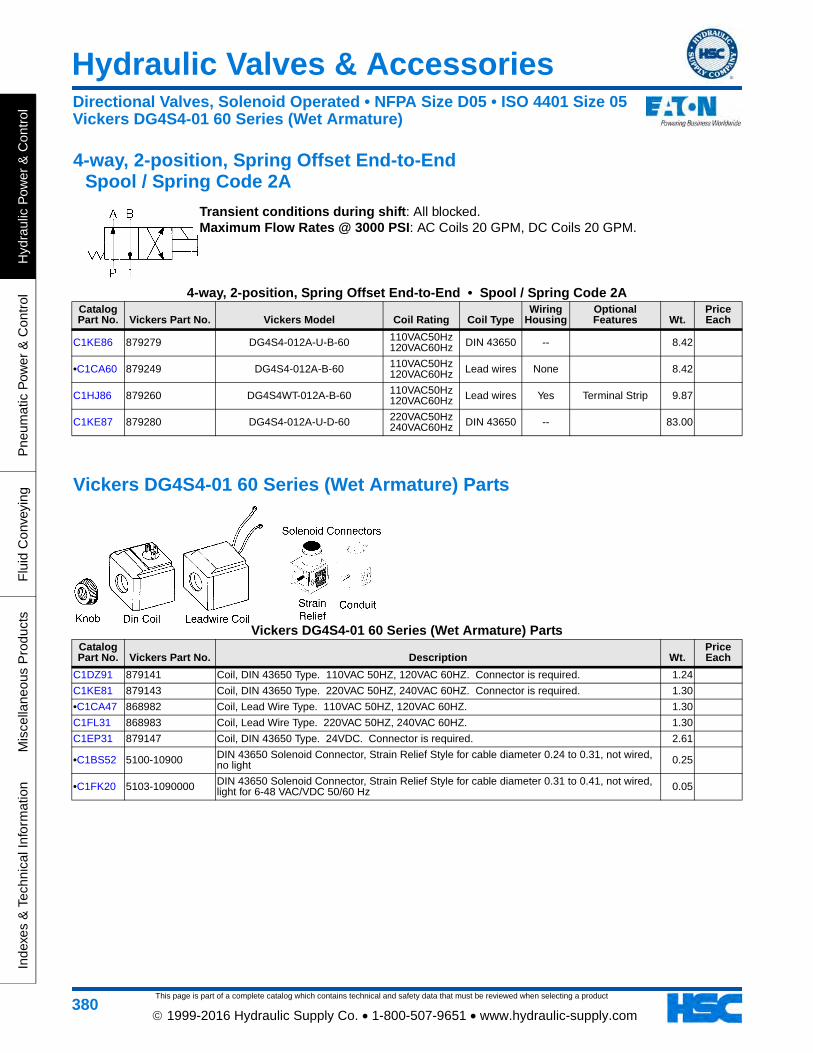
This page is part of a complete catalog which contains technical and safety data that must be reviewed when selecting a product
Hydraulic Valves & Accessories
Hyd
raul
ic P
ower
& C
ontr
olP
neum
atic
Pow
er &
Con
trol
Flu
id C
onve
ying
Mis
cella
neou
s P
rodu
cts
Inde
xes
& T
echn
ical
Info
rmat
ion
380 1999-2016 Hydraulic Supply Co. • 1-800-507-9651 • www.hydraulic-supply.com
4-way, 2-position, Spring Offset End-to-End Spool / Spring Code 2A
Transient conditions during shift: All blocked. Maximum Flow Rates @ 3000 PSI: AC Coils 20 GPM, DC Coils 20 GPM.
4-way, 2-position, Spring Offset End-to-End • Spool / Spring Code 2ACatalog Part No. Vickers Part No. Vickers Model Coil Rating Coil Type
Wiring Housing
Optional Features Wt.
Price Each
C1KE86 879279 DG4S4-012A-U-B-60 110VAC50Hz 120VAC60Hz DIN 43650 -- 8.42
•C1CA60 879249 DG4S4-012A-B-60 110VAC50Hz 120VAC60Hz Lead wires None 8.42
C1HJ86 879260 DG4S4WT-012A-B-60 110VAC50Hz 120VAC60Hz Lead wires Yes Terminal Strip 9.87
C1KE87 879280 DG4S4-012A-U-D-60 220VAC50Hz 240VAC60Hz DIN 43650 -- 83.00
Vickers DG4S4-01 60 Series (Wet Armature) Parts
Vickers DG4S4-01 60 Series (Wet Armature) PartsCatalog Part No. Vickers Part No. Description Wt.
Price Each
C1DZ91 879141 Coil, DIN 43650 Type. 110VAC 50HZ, 120VAC 60HZ. Connector is required. 1.24
C1KE81 879143 Coil, DIN 43650 Type. 220VAC 50HZ, 240VAC 60HZ. Connector is required. 1.30
•C1CA47 868982 Coil, Lead Wire Type. 110VAC 50HZ, 120VAC 60HZ. 1.30
C1FL31 868983 Coil, Lead Wire Type. 220VAC 50HZ, 240VAC 60HZ. 1.30
C1EP31 879147 Coil, DIN 43650 Type. 24VDC. Connector is required. 2.61
•C1BS52 5100-10900 DIN 43650 Solenoid Connector, Strain Relief Style for cable diameter 0.24 to 0.31, not wired, no light 0.25
•C1FK20 5103-1090000 DIN 43650 Solenoid Connector, Strain Relief Style for cable diameter 0.31 to 0.41, not wired, light for 6-48 VAC/VDC 50/60 Hz 0.05
Directional Valves, Solenoid Operated • NFPA Size D05 • ISO 4401 Size 05Vickers DG4S4-01 60 Series (Wet Armature)

This page is part of a complete catalog which contains technical and safety data that must be reviewed when selecting a product
Hydraulic Valves & Accessories
Hydraulic P
ower &
Control
Pneum
atic Pow
er & C
ontrolF
luid Conveying
Miscellaneous P
roductsIndexes &
Technical Information
381 1999-2016 Hydraulic Supply Co. • 1-800-507-9651 • www.hydraulic-supply.com
Vickers® DG4V4-01 10 Series (Wet Armature, High Pressure) • To 30 GPM
Features: High pressure & flow capability. Plug-in solenoid coils for ease of servicing. Spool cushioning passage equalizes hydraulic force on ends of spool and cushions spool shift. Wet Armature design for quieter operation and long life with no dynamic seal leakage. Molded coil is impervious to moisture & dirt. Buna-N seals standard (Viton® available). Direct Acting type.
Maximum Operating Pressure: Ports P, A & B 4570 PSI with petroleum oil, 1000 PSI with High Water Base fluids. (CAUTION: Pressures over 3000 PSI require steel subplate or manifold). Port T 1750 PSI with Standard Power coils, 1000 PSI with Low Power Coils.
Maximum Flow Rates: Dependant on spool/spring combination and coil.Recommended Operating Temperature Range: 70°F to 120°F.Mounting Considerations: Detented models should mount with longitudinal axis horizontal. Other models may
be mounted in any position.Note: These valves are available in a wide variety of configurations not shown in this catalog. Contact us for
detailed information.Size D05 Subplates & Manifolds: page 452Solenoid Connectors: page 446(Required on models that use DIN 43650 connectors).Mounting Bolts: Standard mounting bolts are 4ea 1/4-20 x 1-1/2 Grade 8 socket head capscrews (Vickers Bolt Kit
255633), torqued to 112 lb.in. maximum with threads lubricated. See Bolt Kits on page 440Dimensions & Technical Information: page 679
4-way, 2-position, Spring Offset End-to-End Spool / Spring Code 0A
Transient conditions during shift: All Open. Maximum Flow Rates @ 3000 PSI: Standard AC Coils 30 GPM, Low Powered AC Coils 20 GPM. Standard DC Coils 30 GPM, Low Powered DC Coils 15 GPM (1500 PSI limit).
4-way, 2-position, Spring Offset End-to-End • Spool / Spring Code 0ACatalog Part No. Vickers Part No. Vickers Model Coil Rating Coil Type
Wiring Housing
Optional Features Wt.
Price Each
C1HH49 02-363741 DG4V4-010A-M-W-L-B-5-10 110VAC50Hz 120VAC60Hz Plug-In Yes Std. Power Coil,
Lights 9.61
Directional Valves, Solenoid Operated • NFPA Size D05 • ISO 4401 Size 05Vickers DG4V4-01 10 Series (Wet Armature, High Pressure)

This page is part of a complete catalog which contains technical and safety data that must be reviewed when selecting a product
Hydraulic Valves & Accessories
Hyd
raul
ic P
ower
& C
ontr
olP
neum
atic
Pow
er &
Con
trol
Flu
id C
onve
ying
Mis
cella
neou
s P
rodu
cts
Inde
xes
& T
echn
ical
Info
rmat
ion
382 1999-2016 Hydraulic Supply Co. • 1-800-507-9651 • www.hydraulic-supply.com
Vickers® DG4V5 20 Series (Wet Armature, High Pressure) • To 32 GPM
Features: Four-land spool design to facilitate smooth, variable valve response speeds • AC and DC wet-armature solenoid options with ISO 4400 (DIN 43650) electrical connections and manual overrides • Variable speed changeover potential in all DC models • Many spool types; in spring-offset, spring-centered and detented arrangements.Maximum Operating Pressure: Ports P, A & B 4500 PSI (CAUTION: Pressures over 3000 PSI require steel subplate or manifold). Ports T 1750 PSI for AC solenoids, 2325
PSI for DC solenoids.Maximum Flow Rates: Dependant on spool/spring combination and coil.Fluid Temperature: -4°F to 150°F Recommended Operating Range, -4°F to 158°F Extreme Range.Fluid Viscosity: 70 to 245 SSU Recommended Operating Range, 70 to 2300 SSU Extreme Range.Ambient Temperature: AC 60Hz Valves: -4°F to 104°F. AC 50Hz Valves: -4°F to 122°F. DC Valves: -4°F to
158°F.Recommended Filtration Level: ISO Cleanliness Level 20/18/15 (Up to 3050 PSI), 19/17/14 (Above 3050 PSI).Note: Ratings based on using anti wear hydraulic fluid. For ratings on use with other fluids, contact us for
assistance.Note: These valves are available in a wide variety of configurations not shown in this catalog. Contact us for
detailed information.Mounting Considerations: Detented models should mount with longitudinal axis horizontal. Other models may
be mounted in any position.Size D05 Subplates & Manifolds: page 452Solenoid Connectors: page 446(Required on models that use DIN 43650 connectors).Mounting Bolts: Standard mounting bolts are 4ea 1/4-20 x 1-1/2 Grade 8 socket head capscrews (Vickers Bolt Kit
255633), torqued to 112 lb.in. maximum with threads lubricated. See Bolt Kits on page 440Dimensions & Technical Information: page 680
4-way, 2-position, Spring Offset Spool / Spring Code 2A
Transient conditions during shift: All blocked. Maximum Flow Rates @ 3000 PSI: AC Coils 25 GPM, DC Coils 25 GPM.
4-way, 2-position, Spring Offset • Spool / Spring Code 2ACatalog Part No. Vickers Part No. Vickers Model Coil Rating Optional Features Wt.
Price Each
C1KK66 639393 DG4V-5-2A-M-EK6-20 115VAC60Hz 7.74
Directional Valves, Solenoid Operated • NFPA Size D05 • ISO 4401 Size 05Vickers DG4V5-01 20 Series (Wet Armature, High Pressure)

This page is part of a complete catalog which contains technical and safety data that must be reviewed when selecting a product
Hydraulic Valves & Accessories
Hydraulic P
ower &
Control
Pneum
atic Pow
er & C
ontrolF
luid Conveying
Miscellaneous P
roductsIndexes &
Technical Information
383 1999-2016 Hydraulic Supply Co. • 1-800-507-9651 • www.hydraulic-supply.com
4-way, 3-position, Spring Centered Spool / Spring Code 2C
Transient conditions during shift: P to A: All blocked. P to B: All blocked. Maximum Flow Rates @ 3000 PSI: AC Coils 30 GPM, DC Coils 30 GPM.
4-way, 3-position, Spring Centered • Spool / Spring Code 2CCatalog Part No. Vickers Part No. Vickers Model Coil Rating Optional Features Wt.
Price Each
C1KC44 616776 DG4V-5-2CJ-M-U-H6-20 24VDC 12.40
Vickers DG4V-5 20 Series Parts
Vickers DG4V-5 20 Series PartsCatalog Part No. Vickers Part No. Description Wt. Price Each
C1JR85 617499 Coil 115 VAC / 60 Hz 1.21
Directional Valves, Solenoid Operated • NFPA Size D05 • ISO 4401 Size 05Vickers DG4V5-01 20 Series (Wet Armature, High Pressure)

This page is part of a complete catalog which contains technical and safety data that must be reviewed when selecting a product
Hydraulic Valves & Accessories
Hyd
raul
ic P
ower
& C
ontr
olP
neum
atic
Pow
er &
Con
trol
Flu
id C
onve
ying
Mis
cella
neou
s P
rodu
cts
Inde
xes
& T
echn
ical
Info
rmat
ion
384 1999-2016 Hydraulic Supply Co. • 1-800-507-9651 • www.hydraulic-supply.com
Vickers® DG4S4-01 60 Series (Soft Shift, Wet Armature) • Flows to 20 GPM
Features: Low cost alternative to proportional valves. Conventional direct-acting solenoid design with controlled solenoid shift speed. Wet Armature design for quieter operation and long life with no dynamic seal leakage. Molded coil is impervious to moisture & dirt. Viton® seals standard.Operating Principles: Spools with contoured or notched lands are used to provide maximum control of flow rate change as the spool is shifted. DC solenoids prevent coil
burnout during controlled rate of solenoid shift. Spool shift speed is controlled by a metering orifice in the solenoid. Three orifice sizes are available. Conventional alternating current (120VAC 60HZ or 110VAC 50HZ) input is converted to DC through a rectifier located in the valve's terminal box.
Maximum Operating Pressure: Ports P, A & B 3600 PSI with petroleum oil, 1000 PSI with High Water Base fluids. (CAUTION: Pressures over 3000 PSI require steel subplate or manifold). Port T 1000 PSI.
Maximum Flow Rates: Dependant on spool/spring combination and coil. See Technical Information section.Recommended Operating Temperature Range: 20°F to 180°F.Plumbing Note: To fully utilize the features of the soft shift solenoid, the core tubes must remain full of oil. The
tank line must be plumbed so that the tank port is always flooded with oil. Addition of a back pressure check may be required to prevent bleed down.
Bleeding Procedure: Apply a minimum of 50 PSI tank pressure. Shift either solenoid. Loosen manual actuators in solenoid ends until air is evacuated. Tighten manual actuators. No further bleeding should be required.
Technical Information: page 677Note: These valves are available in a wide variety of configurations not shown in this catalog. Contact us for
detailed information.Size D05 Subplates & Manifolds: page 452Solenoid Connectors: page 446(Required on models that use DIN 43650 connectors).Mounting Bolts: Standard mounting bolts are 4ea 1/4-20 x 1-1/2 Grade 8 socket head capscrews (Vickers Bolt Kit
255633), torqued to 112 lb.in. maximum with threads lubricated. See Bolt Kits on page 440
4-way, 3-position, spring centered Spool / Spring Code 0C
Transient conditions during shift: P to A: All open. P to B: All open. Maximum Flow Rate @ 3000 PSI: 16 GPM.
4-way, 3-position, spring centered • Spool / Spring Code 0C
Catalog Part No. Vickers Part No. Vickers Model Valve's Electrical Features
Input Electrical Requirements
Soft Shift
Orifice Dia (in) Wt.
Price Each
C1AD42 02-300110 DG4S4W-010C-BB-60-S491 1/2 NPT Terminal Box with Rectifier Board
110VAC 50HZ 120VAC 60HZ 0.047 11.07
Directional Valves, Solenoid Operated • NFPA Size D05 • ISO 4401 Size 05Vickers DG4S4-01 60 Series (Soft Shift, Wet Armature)
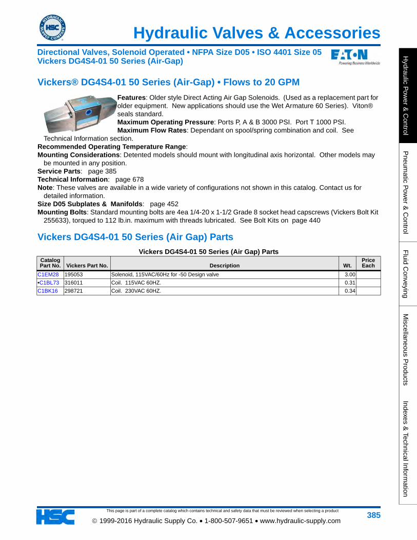
This page is part of a complete catalog which contains technical and safety data that must be reviewed when selecting a product
Hydraulic Valves & Accessories
Hydraulic P
ower &
Control
Pneum
atic Pow
er & C
ontrolF
luid Conveying
Miscellaneous P
roductsIndexes &
Technical Information
385 1999-2016 Hydraulic Supply Co. • 1-800-507-9651 • www.hydraulic-supply.com
Vickers® DG4S4-01 50 Series (Air-Gap) • Flows to 20 GPM
Features: Older style Direct Acting Air Gap Solenoids. (Used as a replacement part for older equipment. New applications should use the Wet Armature 60 Series). Viton® seals standard.Maximum Operating Pressure: Ports P, A & B 3000 PSI. Port T 1000 PSI.Maximum Flow Rates: Dependant on spool/spring combination and coil. See
Technical Information section.Recommended Operating Temperature Range: Mounting Considerations: Detented models should mount with longitudinal axis horizontal. Other models may
be mounted in any position.Service Parts: page 385Technical Information: page 678Note: These valves are available in a wide variety of configurations not shown in this catalog. Contact us for
detailed information.Size D05 Subplates & Manifolds: page 452Mounting Bolts: Standard mounting bolts are 4ea 1/4-20 x 1-1/2 Grade 8 socket head capscrews (Vickers Bolt Kit
255633), torqued to 112 lb.in. maximum with threads lubricated. See Bolt Kits on page 440
Vickers DG4S4-01 50 Series (Air Gap) Parts
Vickers DG4S4-01 50 Series (Air Gap) PartsCatalog Part No. Vickers Part No. Description Wt.
Price Each
C1EM28 195053 Solenoid, 115VAC/60Hz for -50 Design valve 3.00
•C1BL73 316011 Coil. 115VAC 60HZ. 0.31
C1BK16 298721 Coil. 230VAC 60HZ. 0.34
Directional Valves, Solenoid Operated • NFPA Size D05 • ISO 4401 Size 05Vickers DG4S4-01 50 Series (Air-Gap)

This page is part of a complete catalog which contains technical and safety data that must be reviewed when selecting a product
Hydraulic Valves & Accessories
Hyd
raul
ic P
ower
& C
ontr
olP
neum
atic
Pow
er &
Con
trol
Flu
id C
onve
ying
Mis
cella
neou
s P
rodu
cts
Inde
xes
& T
echn
ical
Info
rmat
ion
386 1999-2016 Hydraulic Supply Co. • 1-800-507-9651 • www.hydraulic-supply.com
Vickers® DG5V-8 Series • Flows to 185 GPM • Pressures to 5000 PSI
Features: Two-stage directional valve with integrally mounted pilot valve. Available with a wide variety of spool and spring arrangements, electrical options, stroke and pilot choke adjustments, integral check valves and port orifices. Solid cast iron body and core passages for maximum strength and minimal pressure drop. High-force solenoids and centering springs assure consistent shifting.Maximum Operating Pressures: Ports P, A & B: 5000 PSI. (CAUTION: Pressures over 3000 PSI require steel subplate or manifold). Port T: See tables below.Maximum Flow Rates: Dependant on spool/spring combination and coil. See Technical Information section.
Recommended Operating Temperature Range: 0°F to 150°F.Mounting Considerations: Detented models should mount with longitudinal axis horizontal. Other models may
be mounted in any position.Note: These valves are available in a wide variety of configurations not shown in this catalog. Contact us for
detailed information.Service Parts: Pilot valve parts page 375Technical Information: page 681Size D08 Subplates & Manifolds: Solenoid Connectors: page 446(Required on models that use DIN 43650 connectors).Mounting Bolts: Standard mounting bolts are 4ea 1/2-13 x 2-1/2 Grade 8 socket head capscrews (Vickers Bolt Kit
255635), torqued to 700 lb.in. maximum with threads lubricated. See Bolt Kits on page 440
4-way, 3-position, Spring Centered Spool / Spring Code 8C
Transient conditions during shift: All open. Maximum Flow Rate: 185 GPM (At pressures to 5000 PSI).
4-way, 3-position, Spring Centered • Spool / Spring Code 8C
Catalog Part No.
Vickers Part No. Vickers Model Coil Rating Coil Type
Port T Rating (psi)
Minimum Pilot
Pressure (psi) Other Features Wt.
Price Each
C1HH47 02-343827 DG5V-8-H-8C-E-VM-FTWL-B-10
110VAC50Hz 120VAC60Hz
Lead wires Conduit box 5000 75
External Pilot, Internal Drain, Wired Terminal Block, Indicator Lights, High Performance pilot
valve
31.57
Directional Valves, Solenoid Operated • NFPA Size D08 • ISO 4401 Size 08Vickers DG5V-8 Series • To 5000 PSI
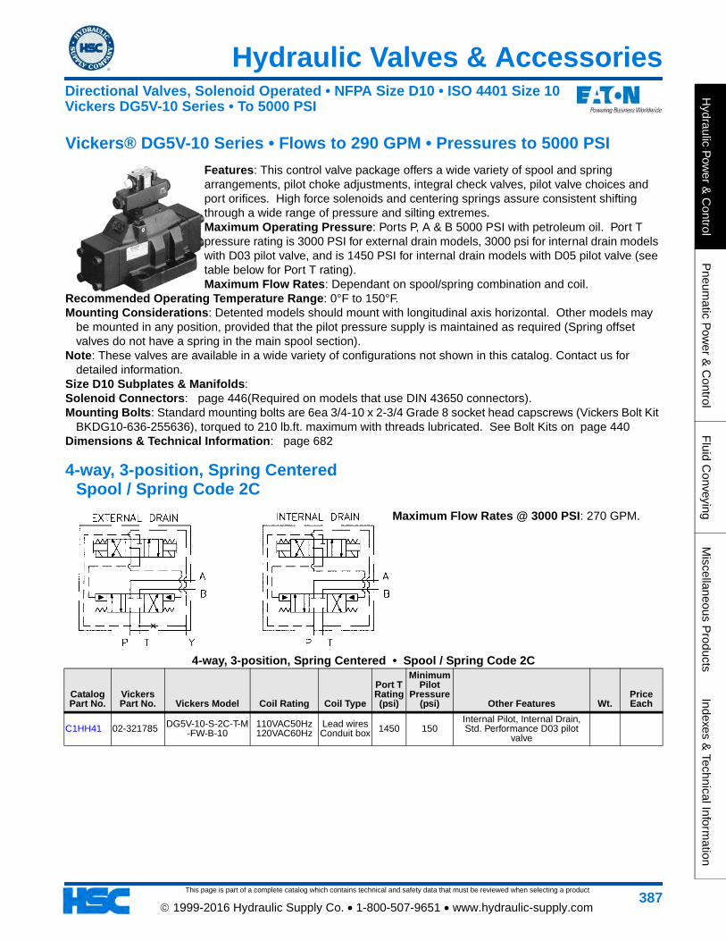
This page is part of a complete catalog which contains technical and safety data that must be reviewed when selecting a product
Hydraulic Valves & Accessories
Hydraulic P
ower &
Control
Pneum
atic Pow
er & C
ontrolF
luid Conveying
Miscellaneous P
roductsIndexes &
Technical Information
387 1999-2016 Hydraulic Supply Co. • 1-800-507-9651 • www.hydraulic-supply.com
Vickers® DG5V-10 Series • Flows to 290 GPM • Pressures to 5000 PSI
Features: This control valve package offers a wide variety of spool and spring arrangements, pilot choke adjustments, integral check valves, pilot valve choices and port orifices. High force solenoids and centering springs assure consistent shifting through a wide range of pressure and silting extremes.Maximum Operating Pressure: Ports P, A & B 5000 PSI with petroleum oil. Port T pressure rating is 3000 PSI for external drain models, 3000 psi for internal drain models with D03 pilot valve, and is 1450 PSI for internal drain models with D05 pilot valve (see table below for Port T rating).Maximum Flow Rates: Dependant on spool/spring combination and coil.
Recommended Operating Temperature Range: 0°F to 150°F.Mounting Considerations: Detented models should mount with longitudinal axis horizontal. Other models may
be mounted in any position, provided that the pilot pressure supply is maintained as required (Spring offset valves do not have a spring in the main spool section).
Note: These valves are available in a wide variety of configurations not shown in this catalog. Contact us for detailed information.
Size D10 Subplates & Manifolds: Solenoid Connectors: page 446(Required on models that use DIN 43650 connectors).Mounting Bolts: Standard mounting bolts are 6ea 3/4-10 x 2-3/4 Grade 8 socket head capscrews (Vickers Bolt Kit
BKDG10-636-255636), torqued to 210 lb.ft. maximum with threads lubricated. See Bolt Kits on page 440Dimensions & Technical Information: page 682
4-way, 3-position, Spring Centered Spool / Spring Code 2C
Maximum Flow Rates @ 3000 PSI: 270 GPM.
4-way, 3-position, Spring Centered • Spool / Spring Code 2C
Catalog Part No.
Vickers Part No. Vickers Model Coil Rating Coil Type
Port T Rating (psi)
Minimum Pilot
Pressure (psi) Other Features Wt.
Price Each
C1HH41 02-321785 DG5V-10-S-2C-T-M-FW-B-10
110VAC50Hz 120VAC60Hz
Lead wires Conduit box 1450 150
Internal Pilot, Internal Drain, Std. Performance D03 pilot
valve
Directional Valves, Solenoid Operated • NFPA Size D10 • ISO 4401 Size 10Vickers DG5V-10 Series • To 5000 PSI

This page is part of a complete catalog which contains technical and safety data that must be reviewed when selecting a product
Hydraulic Valves & Accessories
Hyd
raul
ic P
ower
& C
ontr
olP
neum
atic
Pow
er &
Con
trol
Flu
id C
onve
ying
Mis
cella
neou
s P
rodu
cts
Inde
xes
& T
echn
ical
Info
rmat
ion
388 1999-2016 Hydraulic Supply Co. • 1-800-507-9651 • www.hydraulic-supply.com
Inline Flow Control Valves For Hydraulic (To 12 GPM) & Pneumatic Service
Features: Tamperproof adjustment key is standard. Knurled knob is optional. Locknut is standard. Application: Controlled flow in one direction, free flow in opposite direction. Flow adjustment can be made under
pressure. Setting can be locked with locknut. Brass valves for use in pneumatic systems and lower pressure hydraulic systems. Steel valves for use in hydraulic systems. Pressure ratings in tables are for non-shock service.
Materials: Body: Available in Brass, carbon steel or stainless steel. Needle: Brass on brass valves, 416 stainless steel on steel and stainless steel valves. Backup Washer: Teflon®. Optional Knob: Aluminum. Tamper proof Key: Cadmium plated steel. Retainer and ball: Stainless steel.
Operating Temperature Range: -15°F to 200°F.
Inline Flow Control Valves • For Hydraulic (To 12 GPM) & Pneumatic Service
Catalog Part No. Deltrol Model Size Threads
Body Material
Maximum Operating Pressure
Non-Shock (psi)
Flow Rating (GPM)
CV Factor
A (in)
B (in)
C (in) Wt.
Price Each
•C1CP34 F10B 1/8 1/8-27 NPT Brass 2000 1.5 0.20 0.69 0.88 0.20 0.22
•C1CP38 F20B 1/4 1/4-18 NPT Brass 2000 3.0 0.43 0.88 1.00 0.36 0.43
•C1CP39 F20S 1/4 1/4-18 NPT Steel 5000 3.0 0.43 0.88 1.00 0.36 0.43
•C1CP46 F25B 3/8 3/8-18 NPT Brass 2000 5.0 0.78 1.06 1.81 0.34 0.73
•C1CP47 F25S 3/8 3/8-18 NPT Steel 5000 5.0 0.78 1.06 1.81 0.34 0.67
•C1CP50 F30S 1/2 1/2-14 NPT Steel 5000 8.0 1.24 1.31 1.44 0.47 1.18
Note: Models with K at end of model number have knurled adjustment knob instead of tamperproof adjustment key.
Flow Control Valves
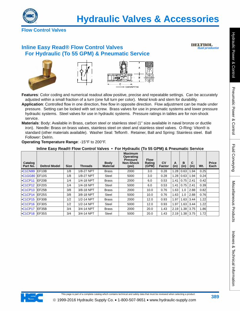
Hydraulic Valves & Accessories
This page is part of a complete catalog which contains technical and safety data that must be reviewed when selecting a product
Hydraulic P
ower &
Control
Pneum
atic Pow
er & C
ontrolF
luid Conveying
Miscellaneous P
roductsIndexes &
Technical Information
389 1999-2016 Hydraulic Supply Co. • 1-800-507-9651 • www.hydraulic-supply.com
Inline Easy Read® Flow Control Valves For Hydraulic (To 55 GPM) & Pneumatic Service
Features: Color coding and numerical readout allow positive, precise and repeatable settings. Can be accurately adjusted within a small fraction of a turn (one full turn per color). Metal knob and stem for durability.
Application: Controlled flow in one direction, free flow in opposite direction. Flow adjustment can be made under pressure. Setting can be locked with set screw. Brass valves for use in pneumatic systems and lower pressure hydraulic systems. Steel valves for use in hydraulic systems. Pressure ratings in tables are for non-shock service.
Materials: Body: Available in Brass, carbon steel or stainless steel (1" size available in naval bronze or ductile iron). Needle: Brass on brass valves, stainless steel on steel and stainless steel valves. O-Ring: Viton® is standard (other materials available). Washer Seal: Teflon®. Retainer, Ball and Spring: Stainless steel. Ball Follower: Delrin.
Operating Temperature Range: -15°F to 200°F.
Inline Easy Read® Flow Control Valves • For Hydraulic (To 55 GPM) & Pneumatic Service
Catalog Part No. Deltrol Model Size Threads
Body Material
Maximum Operating Pressure
Non-Shock (psi)
Flow Rating (GPM)
CV Factor
A (in)
B (in)
C (in) Wt.
Price Each
•C1CN99 EF10B 1/8 1/8-27 NPT Brass 2000 3.0 0.28 1.28 0.63 1.94 0.25
•C1GG80 EF10S 1/8 1/8-27 NPT Steel 5000 3.0 0.28 1.28 0.63 1.94 0.24
•C1CP11 EF20B 1/4 1/4-18 NPT Brass 2000 6.0 0.53 1.41 0.75 2.41 0.42
•C1CP12 EF20S 1/4 1/4-18 NPT Steel 5000 6.0 0.53 1.41 0.75 2.41 0.39
•C1CP13 EF25B 3/8 3/8-18 NPT Brass 2000 10.0 0.76 1.63 1.0 2.88 0.82
•C1CP14 EF25S 3/8 3/8-18 NPT Steel 5000 10.0 0.76 1.63 1.0 2.88 0.76
•C1CP15 EF30B 1/2 1/2-14 NPT Brass 2000 12.0 0.93 1.97 1.63 3.44 1.22
•C1CP16 EF30S 1/2 1/2-14 NPT Steel 5000 12.0 0.93 1.97 1.63 3.44 1.22
•C1CP17 EF35B 3/4 3/4-14 NPT Brass 2000 20.0 1.43 2.19 1.38 3.75 1.86
•C1CP18 EF35S 3/4 3/4-14 NPT Steel 5000 20.0 1.43 2.19 1.38 3.75 1.72
Flow Control Valves

This page is part of a complete catalog which contains technical and safety data that must be reviewed when selecting a product
Hydraulic Valves & Accessories
Hyd
raul
ic P
ower
& C
ontr
olP
neum
atic
Pow
er &
Con
trol
Flu
id C
onve
ying
Mis
cella
neou
s P
rodu
cts
Inde
xes
& T
echn
ical
Info
rmat
ion
390 1999-2016 Hydraulic Supply Co. • 1-800-507-9651 • www.hydraulic-supply.com
Inline Flow Control Valves Vickers® FN Series • To 50 GPM
Description: FN valves are ideally suited for a great number of applications requiring flow regulation without pressure compensation –– applications where the relatively constant nature of the load minimizes the need for pressure compensation. They are not intended to be used as a shut-off valve.
Maximum Pressure: 3000 PSI
Inline Flow Control Valves • Vickers® FN Series • To 50 GPMCatalog Part No.
Vickers Part No. Vickers Model Flow Rating (gpm) A (in)
B (in)
C (in)
D (in)
E (in) F (in)
G (in)
H (in) J (in) Wt.
Price Each
C1JX95 253361 FN-03-20 10 3/8 NPT 2.88 1.44 1.25 1.31 0.65 0.75 1.25 0.44 1.30
Note: Please contact us for technical & application information on these valves.
Inline Pressure Compensated Flow Control Valves Deltrol PC Series • To 30 GPM
Features: Maintains accurate constant flow at pressures up to 3,000 PSI (Non-shock service). Fixed (Factory set PC3 and PC4 models) and Adjustable (PC5 models). Free reverse flow (PC5 models).
Application: Flows are controlled within ±15% up to 1.5 GPM and at ±10% at higher flows up to 30 GPM. Regulation is virtually unaffected by temperature changes from 60°F to 180°F (±2% at 70°F DT, ±4% at 120°F DT). Series 3 and Series 4 models have a restricted reverse flow as limited by the internal orifice. Series 5 models have a free reverse flow.
Materials: Steel body (PC3 and PC5 models), Aluminum body (1/4 and 3/8 PC4 models), Steel body (1/2 and 3/4 PC4 models. Viton® O-Rings. Aluminum knob (PC5 models).
Operating Temperature Range: -15°F to 400°F.
Inline Pressure Compensated Flow Control Valves • Deltrol PC Series • To 30 GPM
Catalog Part No.
Deltrol Model Series Size Threads
Body Material
Maximum Operating Pressure
Non-Shock (psi)
Controlled Flow
Minimum Differential Pressure
(PSI) Dimensions Wt.Price Each
•C1GK41 PC3-2-0.20 Series 3 1/4 1/4-18 NPT Steel 3000 0.20 GPM Fixed 100 A=0.69
B=2.38 0.20
Flow Control Valves

Hydraulic Valves & Accessories
This page is part of a complete catalog which contains technical and safety data that must be reviewed when selecting a product
Hydraulic P
ower &
Control
Pneum
atic Pow
er & C
ontrolF
luid Conveying
Miscellaneous P
roductsIndexes &
Technical Information
391 1999-2016 Hydraulic Supply Co. • 1-800-507-9651 • www.hydraulic-supply.com
Inline Easy Read® Pressure Compensated Flow Control Valves Deltrol EPC Series • To 34 GPM
Features: Pressure Compensated. Color coding and numerical readout allow positive, precise and repeatable settings. Can be accurately adjusted within a small fraction of a turn (one full turn per color). Metal knob and stem for durability.
Application: Controlled flow in one direction, free flow in opposite direction. Valves will start to control flow at 60 to 70 PSI pressure drop. Flow regulated between ± 10% above 1.5 GPM, ± 15% 0.5 to 1.5 GPM. Flow adjustment can be made under pressure. Setting can be locked with set screw. Steel valves for use in hydraulic systems.
Materials: Body: Steel. Needle: Stainless steel. O-Ring: Viton®. Washer: Teflon®. Knob: Aluminum. Piston: Steel. Spring: Music wire.
Operating Temperature Range: -15°F to 200°F.
Inline Easy Read® Pressure Compensated Flow Control Valves • Deltrol EPC Series • To 34 GPM
Catalog Part No. Deltrol Model Size Threads
Maximum Operating Pressure
(PSI)Controlled Flow
Range (GPM)
Minimum Differential
Pressure (PSI)A
(in)B
(in)C
(in) Wt.Price Each
•C1CP31 EPC531 3/8 3/8-18 NPT 3000 1.0 to 10 70 1.97 1.50 5.42 2.47
•C1CP32 EPC541 1/2 1/2-14 NPT 3000 1.5 to 15 70 1.97 1.63 5.88 3.00
Flow Control Valves

This page is part of a complete catalog which contains technical and safety data that must be reviewed when selecting a product
Hydraulic Valves & Accessories
Hyd
raul
ic P
ower
& C
ontr
olP
neum
atic
Pow
er &
Con
trol
Flu
id C
onve
ying
Mis
cella
neou
s P
rodu
cts
Inde
xes
& T
echn
ical
Info
rmat
ion
392 1999-2016 Hydraulic Supply Co. • 1-800-507-9651 • www.hydraulic-supply.com
2-Port Pressure-Compensated Flow Control Valves Eaton 2CFRC60 Series • To 16 GPM
Features: This is a two-port, restrictive flow regulator with a built in free flow check valve. Typical uses include the control of actuator speed by regulating the flow into or out of the actuator (meter-in or meter-out).
Operation: Flow into the inlet of the valve passes through the adjustable orifice and out of the regulated port. The inbuilt check allows free return of flow (2 to 1).
Maximum Flow Rate: 16 GPM. Maximum Operating Pressure: 5000 PSI. Temperature Range: –22° to +194°F Recommended Filtration Level: Cleanliness Level 18/13 or better. Cartridge: Model 2CFRC60-*, sold separately. Housing: Cavity size A7447, sold separately, see page 441
2-Port Pressure-Compensated Flow Control Valves • Eaton 2CFRC60 Series • To 16 GPMCatalog Part No. Eaton Part No. Eaton Model
Maximum Flow Range (GPM)
Adjustment Type Housing Seal Material Wt. Price Each
C1MG49 405AA00054A 2CFRC60P6S 1.6 - 16 Screw None Nitrile 0.64
Flow Control Valves

Hydraulic Valves & Accessories
This page is part of a complete catalog which contains technical and safety data that must be reviewed when selecting a product
Hydraulic P
ower &
Control
Pneum
atic Pow
er & C
ontrolF
luid Conveying
Miscellaneous P
roductsIndexes &
Technical Information
393 1999-2016 Hydraulic Supply Co. • 1-800-507-9651 • www.hydraulic-supply.com
Fixed Priority Flow Control with Relief on Priority Port Vickers® Circuit Maker PFRR-10 • To 6 GPM Regulated
Features: Priority flow pressure compensation • All ports except “T” can be pressurized to 3000 psi • Aluminum in-line type housing • Tamper proof and adjustable relief options • Gauge port • All components in the package are true cartridges and can be removed from the housing without disturbing the plumbing • Note: Some assembly required.
Application: This standard valve package is used to maintain constant flow to priority circuits when input flow is greater than required, regardless of changes in upstream or downstream pressure. It will bypass the rest of the flow to an auxiliary circuit or to tank. Relief valve on a priority port limits pressure on a priority port, as well as ensures bypass flow when there is no demand on priority circuit.
Maximum Inlet Flow: 15 GPM. Regulated Flow Setting: 0.1 - 6.0 GPM (Fixed, non-adjustable) Maximum Operating Pressure: 3000 PSI (All ports except port T). Temperature Range: -40°F to 248°F (Extreme Limits). Recommended Filtration: ISO 4406 Cleanliness Level 18/16/13 or cleaner. Cartridges: Fixed Priority Flow Control Cartridge, PFR1-10-F-0-*, sold separately. Relief Cartridge, RV5-10-*-0-*,
sold separately. Housing: 02-178276, sold separately.
Fixed Priority Flow Control with Relief on Priority Port • Vickers® Circuit Maker PFRR-10 • To 6 GPM Regulated
Catalog Part No. Vickers Part No. Vickers Model
Select (1) housing, (1) flow control cartridge and (1) relief cartridge to make each valve assembly Wt.
Price Each
C1FQ46 02-164209 RV5-10-S-0-35/15 Relief Cartridge, 250-3500 PSI Range (Set at 1500), Screw Adjustment, Buna-N Seals 0.53
•C1FM79 02-164222 RV5-10-S-0-20/12 Relief Cartridge, 100-2000 PSI Range (Set at 1200), Screw Adjustment, Buna-N Seals 0.51
C1AD24 02-164723 RV5-10-S-0-35/14.5 Relief Cartridge, 250-3500 PSI Range (Set at 1450), Screw Adjustment, Buna-N Seals 0.52
Note: Some assembly required. Select (1) housing, (1) flow control cartridge and (1) relief cartridge to make each valve assembly
Flow Control Valves

This page is part of a complete catalog which contains technical and safety data that must be reviewed when selecting a product
Hydraulic Valves & Accessories
Hyd
raul
ic P
ower
& C
ontr
olP
neum
atic
Pow
er &
Con
trol
Flu
id C
onve
ying
Mis
cella
neou
s P
rodu
cts
Inde
xes
& T
echn
ical
Info
rmat
ion
394 1999-2016 Hydraulic Supply Co. • 1-800-507-9651 • www.hydraulic-supply.com
3-Port Pressure Compensated Priority Flow Control Vickers® PFR2-10 Series • To 10 GPM Regulated
Features: Cartridge style (Requires a machined cavity or housing for installation). The flow adjustment range is from the factory set maximum flow rate down to 50% of that rate. Pressure compensated for accurate flow control regardless of changes in input or load pressure.
Application: This valve maintains a constant priority flow from port 1 to port 3 based on the setting adjustment, regardless of pressure changes downstream on port 3. Flow in excess of the priority setting is directed to port 2. If the priority flow at port 3 is blocked, the spool will shift to satisfy the priority flow requirement, thereby closing off flow to port 2.
Maximum Flow Rate: 15 GPM (Inlet), 10 GPM (Priority). Maximum Operating Pressure: 3000 PSI. Temperature Range: -40°F to 248°F (Extreme Limits). Recommended Filtration Level: ISO 4406 Cleanliness Level 18/16/13 or cleaner. Cartridge: Model PFR2-10*, sold separately. Housing: Cavity size C-10-3, sold separately, see page 442
3-Port Pressure Compensated Priority Flow Control • Vickers® PFR2-10 Series • To 10 GPM RegulatedCatalog Part No. Vickers Part No. Vickers Model
Adjustable Flow Range (GPM)
Adjustment Type Housing
Seal Material Wt.
Price Each
C1FQ61 02-165669 PFR2-10-S-0/12.00 6.0 - 12.0 Screw with Locknut None Buna-N 0.50
Housing Types: Aluminum STD (Standard light-duty aluminum 3000 psi maximum). Aluminum FR (Fatigue-rated aluminum 3000 psi maximum). Steel (Fatigue-rated Steel 5000 psi maximum).
Flow Control Valves

Hydraulic Valves & Accessories
This page is part of a complete catalog which contains technical and safety data that must be reviewed when selecting a product
Hydraulic P
ower &
Control
Pneum
atic Pow
er & C
ontrolF
luid Conveying
Miscellaneous P
roductsIndexes &
Technical Information
395 1999-2016 Hydraulic Supply Co. • 1-800-507-9651 • www.hydraulic-supply.com
3-Port Pressure Compensated Priority Flow Control Eaton 2CFP60 Series • To 16 GPM
Features: Cartridge construction gives versatility of application. A valve may be fitted into a line body, a custom designed Hydraulic Integrated Circuit or directly into a cylinder or other actuator. Leakproof adjust screw gives easy, accurate adjustment to required flow setting. Hardened and ground working parts give accurate flow control and long working life.
Application: These valves are priority flow regulators. The flow (and actuator speed) will be largely independent of the load and the pressure conditions. If used to regulate flow from a fixed supply, for example a standard gear or piston pump, the valve will pass the required flow and any surplus flow will be diverted to the bypass port. The bypass flow may be used for a secondary circuit whether the secondary pressure requirement is higher or lower than the regulated pressure. The valve inlet pressure will be approximately 7 bar (100 psi) more than the regulated or bypass pressure, whichever is higher.
Maximum Flow Rate: Inlet: 24 GPM; Regulated Flow: 1 - 16 GPM Maximum Operating Pressure: 5000 PSI Temperature Range: –22°F to +194°F Recommended Filtration Level: BS5540/4 Class 18/13 (25 micron nominal) Cartridge: Model 2CFP60, sold separately. Housing: Cavity size CVA-27-04-0. Housing sold separately.
3-Port Pressure Compensated Priority Flow Control • Eaton 2CFP60 Series • To 16 GPM
Catalog Part No. Eaton Part No. Eaton Model
Adjustable Flow Range
(GPM) Adjustment Type Housing Seal Material Wt. Price Each
C1MJ84 405AA00009A 2CFP60R6S 1 - 16 Handknob adjustment None Nitrile 0.35
Flow Control Valves

This page is part of a complete catalog which contains technical and safety data that must be reviewed when selecting a product
Hydraulic Valves & Accessories
Hyd
raul
ic P
ower
& C
ontr
olP
neum
atic
Pow
er &
Con
trol
Flu
id C
onve
ying
Mis
cella
neou
s P
rodu
cts
Inde
xes
& T
echn
ical
Info
rmat
ion
396 1999-2016 Hydraulic Supply Co. • 1-800-507-9651 • www.hydraulic-supply.com
3-Port Pressure Compensated Priority Flow Control Vickers PFR2-16 Series • To 30 GPM
Feature: Cartridge style (Requires a machined cavity or housing for installation). The flow adjustment range is from the factory set maximum flow rate down to 50% of that rate. Pressure compensated for accurate flow control regardless of changes in input or load pressure.
Application: This valve maintains a constant priority flow from port 1 to port 3 based on the setting adjustment, regardless of pressure changes downstream on port 3. Flow in excess of the priority setting is directed to port 2. If the priority flow at port 3 is blocked, the spool will shift to satisfy the priority flow requirement, thereby closing off flow to port 2.
Maximum Flow Rate: 40 GPM (Inlet), 30 GPM (Priority) Maximum Operating Pressure: 3000 PSI. Temperature Range: -40°F to 248°F (Extreme Limits). Recommended Filtration Level: ISO 4406 Cleanliness Level 18/16/13 or cleaner. Cartridge: Model PFR2-16*, sold separately. Housing: Cavity size C-16-3, sold separately, see page 442
3-Port Pressure Compensated Priority Flow Control • Vickers PFR2-16 Series • To 30 GPMCatalog Part No.
Vickers Part No. Vickers Model
Adjustable Flow Range (GPM) Adjustment Type Seal Material Wt.
Price Each
C1MF99 02-165648 PFR2-16-S-0-/15.00 7.5 - 15.0 Screw with Locknut Buna-N
Flow Control Valves

Hydraulic Valves & Accessories
This page is part of a complete catalog which contains technical and safety data that must be reviewed when selecting a product
Hydraulic P
ower &
Control
Pneum
atic Pow
er & C
ontrolF
luid Conveying
Miscellaneous P
roductsIndexes &
Technical Information
397 1999-2016 Hydraulic Supply Co. • 1-800-507-9651 • www.hydraulic-supply.com
Pressure & Temperature Compensated Flow Control Valves Vickers® F(C)G-02/03 Series • To 28 GPM Regulated
Features: Both pressure and temperature compensated to minimize flow variation resulting from changes in fluid pressure and temperature. 4-1/2 turns of dial from full closed to full open. Subplate mounted. Key lock is standard (2 keys are furnished with valve).
Application: Precise control of flow rate is obtained by rotating the dial. Maximum throttle openings may be limited by addition of spacers to the throttle shaft under the selector dial.
Maximum Operating Pressure: Size -02 Models: 3600 PSI. Size -03 Models: 3000 PSI. Maximum Flow Capacity: Size -02 Models: 10 GPM. Size -03 Models: 28 GPM. Maximum Knob Torque Required: Size -03 Models: 20 lb. in. @ 3000 PSI (Proportional to outlet pressure). Recommended Filtration Level: ISO 4406 Cleanliness Level 19/17/14 or cleaner. Mounting Bolts: Size -02 Models: Standard mounting bolts are (4) 5/16-18 x 2 Grade 8 socket head capscrews
(Vickers Bolt Kit BKFG-02-640), torqued to 305 lb. in. Size -03 Models: Standard mounting bolts are (4) 3/8-16 x 3 Grade 8 socket head capscrews (Vickers Bolt Kit 255645, BKFG-03-645), torqued to 350 lb. in. See Bolt Kits on page 440
Subplates: Size -02 Models: Vickers Model FGM-02-20 (3/8 NPT) or FGM-02X-20 (1/2 NPT) sold separately. Size -03 Models: Vickers Part No. 681670 (Model FGM-03SZ-10) sold separately
Pressure & Temperature Compensated Flow Control Valves • Vickers® F(C)G-02/03 Series • To 28 GPM Regulated
Catalog Part No. Vickers Part No. Vickers Model
Flow Range
Reverse Flow
Check Seal Material Other Features Wt.Price Each
C1KA32 420607 FCG-02-1500-5010 to 1500
in³/minYes Buna-N 8.39
Flow Control Valves

This page is part of a complete catalog which contains technical and safety data that must be reviewed when selecting a product
Hydraulic Valves & Accessories
Hyd
raul
ic P
ower
& C
ontr
olP
neum
atic
Pow
er &
Con
trol
Flu
id C
onve
ying
Mis
cella
neou
s P
rodu
cts
Inde
xes
& T
echn
ical
Info
rmat
ion
398 1999-2016 Hydraulic Supply Co. • 1-800-507-9651 • www.hydraulic-supply.com
3-Port Pressure Compensated Non-Adjustable Constant Volume Priority Divider Brand BG5* Series • To 30 GPM
BG5 is a non-adjustable priority divider that receives a single stream and divides it into a priority stream and an excess stream. The two outlet flows are pressure compensating and the sum of said flows equals the inlet flow.
Features: • PRECISION GROUND HEAT TREATED SPOOL that assures long life. • PRESSURE COMPENSATION for both outlet ports. • PRIORITY FLOW IS PRESET at factory to customer requirements. • EVERY BG IS TESTED for priority flow and pressure compensation. • LARGE METERING SPOOL provides a greater area for the pressure differential to act upon.
Pressure Rating: 3000 PSI Filtration: 30-micron filtration recommended. Materials: • Cast Iron Body • Buna N O-Rings • Heat Treated Steel Spools
3-Port Pressure Compensated Non-Adjustable Constant Volume Priority Divider • Brand BG5* Series • To 30 GPM
Catalog Part No. Brand Model Port Size Flow Range (GPM) Priority Setting
Spool Material Wt. Price Each
C1MK41 BG502-12SAE SAE -12 0 - 30 2 GPM Steel 5.00
C1LB62 BG-508-12SAE SAE -12 0 - 30 8 GPM Steel 5.00
Flow Control Valves

Hydraulic Valves & Accessories
This page is part of a complete catalog which contains technical and safety data that must be reviewed when selecting a product
Hydraulic P
ower &
Control
Pneum
atic Pow
er & C
ontrolF
luid Conveying
Miscellaneous P
roductsIndexes &
Technical Information
399 1999-2016 Hydraulic Supply Co. • 1-800-507-9651 • www.hydraulic-supply.com
3-Port Pressure Compensated Priority Flow Control Valves Brand FC51 Series • To 90 GPM Regulated
Features: Precision ground chrome plated spool for long life. Diamond honed spool bore provides consistent spool fit with low leakage. Every valve is factory tested for shutoff, linearity, max. flow & pressure compensation.
Application: The FC-51 full range pressure compensating variable flow control is designed so that the orifice area varies as the lever is rotated. Fluid travels past the variable orifice, through the compensator spool and then out the controlled flow port. The flow out of the CF port is proportional to the orifice area which can vary from closed to open. The sum of the controlled flow and the excess flow equal the inlet flow, and as the controlled flow increases the excess flow decreases. Both outlets are pressure compensated by a spool that maintains a constant flow while adjusting for pressure. Hunting between a compensated pump and the valve is dampened with a dashpot on the compensator spool. The FC-51 can be used as a 2-port flow control by plugging the excess flow port, and, for best results, limiting the flow to about 50% of the valve's rated flow.
Materials: Cast iron body. Heat treated spools (Stainless steel available). Buna-N O-Rings (Standard). Maximum Operating Pressure: 3000 PSI. Recommended Filtration: 30 micron.
3-Port Pressure Compensated Priority Flow Control Valves • Brand FC51 Series • To 90 GPM RegulatedCatalog Part No. Brand Model Port Size Flow Range (GPM) Spool Material Wt.
Price Each
•C1CQ87 FC-51-3/8 3/8 NPT 0-8 GPM Steel 8.03
•C1CQ83 FC-51-1/2 1/2 NPT 0-16 GPM Steel 7.75
C1MH21 FC51-10SAE -10 SAE 0-16 GPM Steel 8.80
•C1CQ85 FC-51-3/4 3/4 NPT 0-30 GPM Steel 7.60
C1MH22 FC51-12SAE -12 SAE 0-30 GPM Steel 8.20
C1CQ81 FC-51-1 1 NPT 0-50 GPM Steel 30.18
C1CQ82 FC-51-1-1/4 1-1/4 NPT 0-90 GPM Steel 30.18
Flow Control Valves

This page is part of a complete catalog which contains technical and safety data that must be reviewed when selecting a product
Hydraulic Valves & Accessories
Hyd
raul
ic P
ower
& C
ontr
olP
neum
atic
Pow
er &
Con
trol
Flu
id C
onve
ying
Mis
cella
neou
s P
rodu
cts
Inde
xes
& T
echn
ical
Info
rmat
ion
400 1999-2016 Hydraulic Supply Co. • 1-800-507-9651 • www.hydraulic-supply.com
3-Port Pressure Compensated Priority Flow Control Valves (With Relief) Brand FCR51 Series • To 90 GPM Regulated
Features: Precision ground chrome plated spool for long life. Diamond honed spool bore provides consistent spool fit with low leakage. Every valve is factory tested for shutoff, linearity, max. flow & pressure compensation. High lift ball spring relief valve.
Application: The FCR-51 full range pressure compensating variable flow control is designed so that the orifice area varies as the lever is rotated. Fluid travels past the variable orifice, through the compensator spool and then out the controlled flow port. The flow out of the CF port is proportional to the orifice area which can vary from closed to open. Once the pressure on the CF port increases above the relief setting, the relief valve opens and diverts flow to the EX port while maintaining pressure on the CF port. The EX port must be plumbed back to tank for the relief to function. The sum of the controlled flow and the excess flow equal the inlet flow, and as the controlled flow increases the excess flow decreases. Both outlets are pressure compensated by a spool that maintains a constant flow while adjusting for pressure. Hunting between a compensated pump and the valve is dampened with a dashpot on the compensator spool.
Materials: Cast iron body. Heat treated spools (Stainless steel available). Buna-N O-Rings (Standard). Maximum Operating Pressure: 3000 PSI. Recommended Filtration: 30 micron.
3-Port Pressure Compensated Priority Flow Control Valves • (With Relief) Brand FCR51 Series • To 90 GPM Regulated
Catalog Part No. Brand Model Port Size Flow Range (GPM) Spool Material Wt.
Price Each
•C1CT52 FCR-51-3/8 3/8 NPT 0-8 GPM Steel 7.89
•C1CT50 FCR-51-1/2 1/2 NPT 0-16 GPM Steel 7.89
•C1CT51 FCR-51-3/4 3/4 NPT 0-30 GPM Steel 7.58
Flow Control Valves

Hydraulic Valves & Accessories
This page is part of a complete catalog which contains technical and safety data that must be reviewed when selecting a product
Hydraulic P
ower &
Control
Pneum
atic Pow
er & C
ontrolF
luid Conveying
Miscellaneous P
roductsIndexes &
Technical Information
401 1999-2016 Hydraulic Supply Co. • 1-800-507-9651 • www.hydraulic-supply.com
Electronically Adj. Proportional Pressure Compensated Flow Control Brand EFC Series • To 30 GPM
The Brand EFC flow control is an electronically controlled version of the original FC51 style flow control valve. The control flow port (CF) and the excess flow port (EX) remain usable and pressure compensated. As the current to the solenoid increases the variable orifice moves proportionally similar to positioning the rotary side lever on the manual FC’s. The solenoid is connected to the EC Series controls which can be purchased with the EFC valve. The choice of a dashpot size allows you to select a valve that responds to the control box at different rates. Other options are 2-port, free reverse flow and high lift ball spring relief. 2-PORT: The 2-port (2P) option is a modified version of the standard 3-port EFC. This option lets you use the control flow port while the excess port is plugged. A special compensator spool eliminates hunting that can occur between pressure compensated valves and pumps. The 2-port can be converted to a 3-port (by removing the EX plug), but it will not have the same characteristics as the standard 3-port. FREE REVERSE FLOW: The free reverse flow option was designed to be used primarily where cylinders and motors are needed to go in reverse. The flow can only go in reverse from controlled flow (CF) to the inlet (IN). Flow is not metered when it goes in reverse.
Features: Diamond honed spool bore provides consistent spool fit with low leakage • O-ring ports • Every EFC is tested for shutoff, linearity, max. flow, crack open and pressure compensation • Standard 3-port allows for pressure compensated flow out of the CF and EX ports • Manual override • Optional 2-port allows for pressure compensated flow out of CF port • Optional free reverse flow allows fluid to move from the CF port to the inlet • Optional high lift relief.
Pressure Rating: 3000 PSI Materials: Ductile cast iron body. Heat treated steel spools. Buna N O-rings. Heat treated free reverse check seat. Pulse Frequency: 90 to 115 hz Coil: Standard 12VDC: 9.6 ohms, 15 watts, 1.0 amps max. Optional 24VDC: 48 ohms, 15 watts, 0.5 amps max. Response Time: Standard 0.035" dash pot: 375 ms. 0.020" dash pot: 900 ms. 0.093" dash pot: 175 to 350 ms,
flow dependant. Recommended Filtration: 10 micron Spool Leakage: 50 ml/minute @ 1000 PSI on EX port.
Electronically Adj. Proportional Pressure Compensated Flow Control • Brand EFC Series • To 30 GPMCatalog Part No. Brand Part No. Ports
Maximum Flow Range (GPM)
Free Reverse Flow Wt. Price Each
C1MH20 EFC12-30-12R20 SAE -12 0 - 30 No 9.26
Flow Control Valves

This page is part of a complete catalog which contains technical and safety data that must be reviewed when selecting a product
Hydraulic Valves & Accessories
Hyd
raul
ic P
ower
& C
ontr
olP
neum
atic
Pow
er &
Con
trol
Flu
id C
onve
ying
Mis
cella
neou
s P
rodu
cts
Inde
xes
& T
echn
ical
Info
rmat
ion
402 1999-2016 Hydraulic Supply Co. • 1-800-507-9651 • www.hydraulic-supply.com
Proportional Flow Dividers Brand B50 Series • To 30 GPM
Features: Precision ground heat treated spools for long life. Pressure compensation for both outlet ports. Every valve is factory tested for flow ratio and pressure compensation.
Application: The B-50 is a non-adjustable divider that receives a single stream and divides into two streams. The two outlet flows are pressure compensating and the sum of outlet flows equal the inlet flow. Flow is from inlet to outlet only. The standard outlet flow ratio is 50:50. WARNING: Spool may bind if valve is mounted with bolts through valve against a flat surface (housing can distort). Mount valve with rigid spacers between valve body and mounting surface to prevent housing distortion.
Materials: Cast iron body. Buna-N O-Rings. Heat treated steel spool. Maximum Operating Pressure: 3000 PSI. Recommended Filtration: 30 micron.
Proportional Flow Dividers • Brand B50 Series • To 30 GPMCatalog Part No. Brand Model Port Size Inlet Flow Range (GPM) Outlet Flow Ratio Wt.
Price Each
•C1CK97 B-50-1/2 1/2 NPT 8-16 GPM 50:50 4.89
C1MG94 B50-10SAE -10 SAE 8-16 GPM 50:50 5.00
•C1CK98 B-50-3/4 3/4 NPT 16-30 GPM 50:50 5.00
Flow Divider Valves

Hydraulic Valves & Accessories
This page is part of a complete catalog which contains technical and safety data that must be reviewed when selecting a product
Hydraulic P
ower &
Control
Pneum
atic Pow
er & C
ontrolF
luid Conveying
Miscellaneous P
roductsIndexes &
Technical Information
403 1999-2016 Hydraulic Supply Co. • 1-800-507-9651 • www.hydraulic-supply.com
Proportional Flow Dividers (With Free Reverse Flow) Brand B100 Series • To 30 GPM
Features: Precision ground heat treated spools for long life. Pressure compensation for both outlet ports. Free reverse flow. Every valve is factory tested for flow ratio and pressure compensation.
Application: The B-100 is a non-adjustable divider that receives a single stream and divides into two streams. The two outlet flows are pressure compensating and the sum of outlet flows equal the inlet flow. Flow can travel in reverse through both outlet ports and is not metered when going in reverse. The standard outlet flow ratio is 50:50. WARNING: Spool may bind if valve is mounted with bolts through valve against a flat surface (housing can distort). Mount valve with rigid spacers between valve body and mounting surface to prevent housing distortion.
Materials: Cast iron body. Buna-N O-Rings. Heat treated steel spool. Maximum Operating Pressure: 3000 PSI. Recommended Filtration: 30 micron.
Proportional Flow Dividers (With Free Reverse Flow) • Brand B100 Series • To 30 GPMCatalog Part No. Brand Model Port Size Inlet Flow Range (GPM) Outlet Flow Ratio Wt.
Price Each
•C1CK93 B100-3/8 3/8 NPT 2-8 GPM 50:50 4.91
•C1CK92 B-100-3/4 3/4 NPT 16-30 GPM 50:50 4.64
Flow Divider Valves

This page is part of a complete catalog which contains technical and safety data that must be reviewed when selecting a product
Hydraulic Valves & Accessories
Hyd
raul
ic P
ower
& C
ontr
olP
neum
atic
Pow
er &
Con
trol
Flu
id C
onve
ying
Mis
cella
neou
s P
rodu
cts
Inde
xes
& T
echn
ical
Info
rmat
ion
404 1999-2016 Hydraulic Supply Co. • 1-800-507-9651 • www.hydraulic-supply.com
Proportional Flow Dividers (With Combining Feature) Vickers® FDC1-10 Series • To 12 GPM
Application: The Vickers FDC1-10 Divider/Combiner proportionally divides a single flow of hydraulic oil into two equal or unequal flows, and combines in the reverse direction. The flow ratios remain constant despite load differences between the ports. Accuracy is ± 10% when used within the recommended flow range. A special feature of the FDC1 valve is that it provides rephase flow to either port when one is blocked. Example: If one cylinder bottoms out first, the opposite cylinder is provided with rephase flow to allow it to bottom out also.
Flow Ratings: Nominal Inlet Flow 12 GPM (18 GPM Maximum). Maximum Operating Pressure: 3000 PSI. Accuracy: ± 10%. Temperature Range: -40°F to 248°F (Extreme Limits). Recommended Filtration Level: ISO 4406 Cleanliness Level 18/16/13 or cleaner. Cartridge: Model FDC1-10*, sold separately. Housing: Cavity size C-10-4, sold separately, see page 443
Proportional Flow Dividers (With Combining Feature) • Vickers® FDC1-10 Series • To 12 GPMCatalog Part No.
Vickers Part No. Vickers Model
Inlet Flow Range (GPM)
Outlet Flow Ratio (Port 4:Port2) Housing Seals Wt.
Price Each
•C1EL11 566003 FDC1-10-0-11 0.74 - 2.9 50:50 None Buna-N 0.22
Housing Types: Aluminum STD (Standard light-duty aluminum 3000 psi maximum). Aluminum FR (Fatigue-rated aluminum 3000 psi maximum). Steel (Fatigue-rated Steel 5000 psi maximum).
Flow Divider Valves

This page is part of a complete catalog which contains technical and safety data that must be reviewed when selecting a product
Hydraulic Valves & Accessories
Hydraulic P
ower &
Control
Pneum
atic Pow
er & C
ontrolF
luid Conveying
Miscellaneous P
roductsIndexes &
Technical Information
405 1999-2016 Hydraulic Supply Co. • 1-800-507-9651 • www.hydraulic-supply.com
Brass Gate Valves Brass M Gate Valve
Features: Screw-in bonnet. Application: For water and steam service. Maximum Operating Pressure: 125 WSP (steam), 200 PSI (WOG).
Brass Gate Valves • Brass M Gate ValveCatalog Part No. ACR Model Ports Wt. Price Each
•C1KU82 3801 3/8 0.57
•C1KU83 3802 1/2 0.51
•C1KU84 3803 3/4 0.85
•C1KU85 3804-ACR 1 1.20
•C1KU86 3805 1-1/4 1.70
•C1KU87 3806-ACR 1-1/2 2.20
•C1KU88 3807-ACR 2 3.30
Gate Valves

This page is part of a complete catalog which contains technical and safety data that must be reviewed when selecting a product
Hydraulic Valves & Accessories
Hyd
raul
ic P
ower
& C
ontr
olP
neum
atic
Pow
er &
Con
trol
Flu
id C
onve
ying
Mis
cella
neou
s P
rodu
cts
Inde
xes
& T
echn
ical
Info
rmat
ion
406 1999-2016 Hydraulic Supply Co. • 1-800-507-9651 • www.hydraulic-supply.com
Differential Pressure Sense Valve Vickers® DPS2-20 Series • To 80 GPM
Features: The DPS2-20 is a differential pressure sensing valve, available as either a spool or poppet type and with either, internal or external pilot.
Application: This valve is used as a main section of a pilot controlled valve assembly. This valve has multiple uses when used with either directional control, flow control or pressure control cartridges.
Maximum Flow Rate: 80 GPM Maximum Operation Pressure: 4200 PSI (spool type), 5000 PSI poppet type) Temperature Range: -40° F to 248° F Recommended Filtration Level: Cleanliness code 18/16/13 Cartridge: Model DPS2-20-*, sold separately Housing: Cavity size C-20-3S, sold seperately, see page 442
Differential Pressure Sense Valve • Vickers® DPS2-20 Series • To 80 GPMCatalog Part No.
Vickers Part No. Vickers Model Function Stroke Adjustment
Differential Pressure Setting Wt.
Price Each
C1DU34 02-153254 DPS2-20-T-F-0-40 Poppet, bi-directional,pilot to close, 2:1 ratio, N/C None (Fixed stroke) 40 PSI
C1NA11 889303 DPS2-20-T-F-0-80 Poppet, bi-directional,pilot to close, 2:1 ratio, N/C None (Fixed stroke) 80 PSI
Logic Element Valves

Hydraulic Valves & Accessories
This page is part of a complete catalog which contains technical and safety data that must be reviewed when selecting a product
Hydraulic P
ower &
Control
Pneum
atic Pow
er & C
ontrolF
luid Conveying
Miscellaneous P
roductsIndexes &
Technical Information
407 1999-2016 Hydraulic Supply Co. • 1-800-507-9651 • www.hydraulic-supply.com
Inline Needle Valves For Hydraulic (To 34 GPM) & Pneumatic Service
Features: Wide adjustment range due to fine thread. Tamperproof adjustment key is standard. Knurled knob is optional. Locknut is standard.
Application: Controlled flow in both directions. Flow adjustment can be made under pressure. Setting can be locked with locknut. Brass valves for use in pneumatic systems and lower pressure hydraulic systems. Steel valves for use in hydraulic systems. Pressure ratings in tables are for non-shock service.
Materials: Body: Available in Brass, carbon steel or stainless steel. Needle: Brass on brass valves, 416 stainless steel on steel and stainless steel valves. O-Ring Packing: Viton®. Backup Washer: Teflon®. Optional Knob: Aluminum. Tamper proof Key: Cadmium plated steel.
Operating Temperature Range: -15°F to 400°F.
Inline Needle Valves • For Hydraulic (To 34 GPM) & Pneumatic Service
Catalog Part No. Deltrol Model Size Threads
Body Material
Maximum Operating Pressure
Non-Shock (psi)
Flow Rating (GPM)
CV Factor
A (in)
B (in)
E (in) Wt.
Price Each
C1DF59 N20B 1/4 1/4-18 NPT Brass 2000 7.0 0.43 0.88 1.00 2.00 0.39
•C1DF61 N25B 3/8 3/8-18 NPT Brass 2000 13.5 0.78 1.06 1.81 2.25 0.59
Note: Models with K at end of model number have knurled adjustment knob instead of tamperproof adjustment key.
Needle Valves

This page is part of a complete catalog which contains technical and safety data that must be reviewed when selecting a product
Hydraulic Valves & Accessories
Hyd
raul
ic P
ower
& C
ontr
olP
neum
atic
Pow
er &
Con
trol
Flu
id C
onve
ying
Mis
cella
neou
s P
rodu
cts
Inde
xes
& T
echn
ical
Info
rmat
ion
408 1999-2016 Hydraulic Supply Co. • 1-800-507-9651 • www.hydraulic-supply.com
Inline Easy Read® Needle Valves For Hydraulic (To 100 GPM) & Pneumatic Service
Features: Color coding and numerical readout allow positive, precise and repeatable settings. Can be accurately adjusted within a small fraction of a turn (one full turn per color). Metal knob and stem for durability.
Application: Controlled flow in both directions. Flow adjustment can be made under pressure. Setting can be locked with set screw. Brass valves for use in pneumatic systems and lower pressure hydraulic systems. Steel valves for use in hydraulic systems. Pressure ratings in tables are for non-shock service.
Materials: Body: Available in Brass, carbon steel or stainless steel (1" size available in naval bronze or ductile iron). Needle: Brass on brass valves, stainless steel on steel and stainless steel valves. O-Ring: Viton® is standard (other materials available). Washer Seal: Teflon®. Knob: Aluminum.
Operating Temperature Range: -15°F to 400°F.
Inline Easy Read® Needle Valves • For Hydraulic (To 100 GPM) & Pneumatic Service
Catalog Part No. Deltrol Model Size Threads
Body Material
Maximum Operating Pressure
Non-Shock (psi)
Flow Rating (GPM)
CV Factor
A (in)
B (in)
D (in) Wt.
Price Each
•C1CP21 EN10B 1/8 1/8-27 NPT Brass 2000 4.5 0.25 1.28 0.63 1.44 0.19
•C1CP22 EN10S 1/8 1/8-27 NPT Steel 5000 4.5 0.25 1.28 0.63 1.44 0.19
•C1CP23 EN20B 1/4 1/4-18 NPT Brass 2000 10.0 0.51 1.41 0.75 2.56 0.32
•C1CP24 EN20S 1/4 1/4-18 NPT Steel 5000 10.0 0.51 1.41 0.75 2.56 0.29
•C1CP25 EN25B 3/8 3/8-18 NPT Brass 2000 18.0 0.92 1.63 1.00 3.25 0.63
•C1CP26 EN25S 3/8 3/8-18 NPT Steel 5000 18.0 0.92 1.63 1.00 3.25 0.59
•C1CP27 EN30B 1/2 1/2-14 NPT Brass 2000 28.0 1.20 1.97 1.13 3.56 0.91
•C1CP28 EN30S 1/2 1/2-14 NPT Steel 5000 28.0 1.20 1.97 1.13 3.56 0.83
•C1CP29 EN35B 3/4 3/4-14 NPT Brass 2000 40.0 1.84 2.19 1.38 4.13 1.46
•C1CP30 EN35S 3/4 3/4-14 NPT Steel 5000 40.0 1.84 2.19 1.38 4.13 0.05
Needle Valves

Hydraulic Valves & Accessories
This page is part of a complete catalog which contains technical and safety data that must be reviewed when selecting a product
Hydraulic P
ower &
Control
Pneum
atic Pow
er & C
ontrolF
luid Conveying
Miscellaneous P
roductsIndexes &
Technical Information
409 1999-2016 Hydraulic Supply Co. • 1-800-507-9651 • www.hydraulic-supply.com
Inline Needle Valves For Hydraulic & Pneumatic Service
Features: Bar stock construction for reliable performance. Hard seats. Bonnet is threaded for optional panel mounting.
Application: Controlled flow in both directions. Materials: Zinc plated AISI 1213 alloy steel body & bonnet. 316 stainless steel hardened stem. Black
polyethylene bonnet cap. Yellow cast aluminum handle (1/8 - 1/2 sizes). Yellow malleable iron handle (3/4-1 sizes). Grafiflex packing.
Maximum Operating Pressure: 10,000 PSI. (Minimum burst pressure is 20,000 PSI). Operating Temperature Range: -100°F to 500°F.
Inline Needle Valves • For Hydraulic & Pneumatic ServiceCatalog Part No. Marsh Model Size Threads
CV Factor A (in) B (in) C (in) D (in) E (in) G (in) J (in) Wt.
Price Each
•C1DF55 N1512 1/4 1/4 NPT 0.4 3.06 1.03 2.06 2.50 1.00 0.38 0.78 0.77
•C1DF56 N1513 3/8 3/8 NPT 0.9 3.75 1.44 2.88 2.50 1.38 0.75 0.91 1.59
•C1DF57 N1514 1/2 1/2 NPT 1.1 3.75 1.44 2.88 2.50 1.38 0.75 0.91 1.50
Needle Valves

This page is part of a complete catalog which contains technical and safety data that must be reviewed when selecting a product
Hydraulic Valves & Accessories
Hyd
raul
ic P
ower
& C
ontr
olP
neum
atic
Pow
er &
Con
trol
Flu
id C
onve
ying
Mis
cella
neou
s P
rodu
cts
Inde
xes
& T
echn
ical
Info
rmat
ion
410 1999-2016 Hydraulic Supply Co. • 1-800-507-9651 • www.hydraulic-supply.com
Cartridge Type Needle Valves Vickers® NV1-10 Series • To 12 GPM
Features: Cartridge style (Requires a machined cavity or housing for installation). Rotary knob. Application: Controlled flow in both directions. Rated Flow: 12 GPM. Maximum Operating Pressure: 3000 PSI. Temperature Range: -40°F to 248°F (Extreme Limits). Recommended Filtration Level: ISO 4406 Cleanliness Level 18/16/13 or cleaner. Cartridge: Model NV1-10*, sold separately. Housing: Cavity size C-10-2, sold separately, see page 441
Cartridge Type Needle Valves • Vickers® NV1-10 Series • To 12 GPMCatalog Part No. Vickers Part No. Vickers Model
Knob Color Housing
Seal Material Wt.
Price Each
C1GH56 565590 NV1-10-K-0 Black None Buna-N 0.23
Parts for Vickers® NV1-10 Needle Valve CartridgesCatalog Part No. Part Number Description Wt.
Price Each
C1FK22 565806 SK2-10-2 Buna-N Seal Kit 0.01
Needle Valves

Hydraulic Valves & Accessories
This page is part of a complete catalog which contains technical and safety data that must be reviewed when selecting a product
Hydraulic P
ower &
Control
Pneum
atic Pow
er & C
ontrolF
luid Conveying
Miscellaneous P
roductsIndexes &
Technical Information
411 1999-2016 Hydraulic Supply Co. • 1-800-507-9651 • www.hydraulic-supply.com
Brass 2-Way Shut-Off Plug Valves Male Pipe to Female Pipe (Straight)
Features: Instantaneous on-off operation with 360° handle rotation. Lapped brass body and plug are individually mated, providing an excellent quality, low friction valve.
Application: Used extensively for water process piping and air supply systems. Maximum Operating Pressure: 30 PSI. Operating Temperature Range: -40°F to 250°F.
Brass 2-Way Shut-Off Plug Valves • Male Pipe to Female Pipe (Straight)Catalog Part No.
Anderson Brass Model Size Threads Wt.
Price Each
•C1AK34 130C-L 1/4 1/4 NPT 0.20
Brass 3-Way Side Outlet Plug Valves Female Pipe
Features: Pointer lever to indicate port selection. Audible Click mechanism is standard. Valves are not lubricated and require no lubrication. O-Ring sealed cap and stem. Brass body and CELCON® plug produce a fine seal that will not seize or gall.
Application: Generally recommended for operation in gasoline, oil, air, water and detergent systems. Maximum Operating Pressure: 30 PSI. Operating Temperature Range: -40°F to 180°F.
Brass 3-Way Side Outlet Plug Valves • Female PipeCatalog Part No.
Anderson Brass Model Size Threads
Fluid Port Dia. (in) Handle Movement Features L (in) Wt.
Price Each
•C1BB99 210C-N 3/8 3/8 NPT 0.312 Click is felt at each position. Handle rotates 360°. 1.375 0.50
Plug Valves
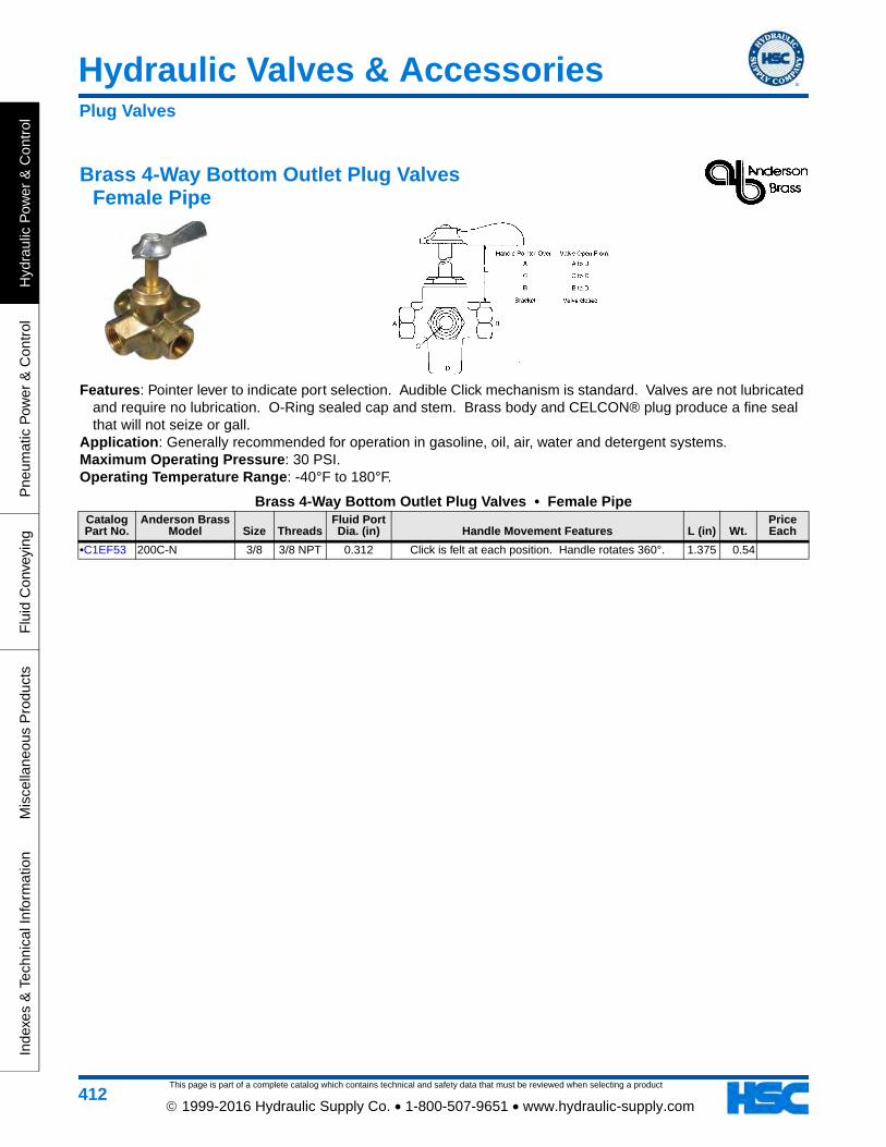
This page is part of a complete catalog which contains technical and safety data that must be reviewed when selecting a product
Hydraulic Valves & Accessories
Hyd
raul
ic P
ower
& C
ontr
olP
neum
atic
Pow
er &
Con
trol
Flu
id C
onve
ying
Mis
cella
neou
s P
rodu
cts
Inde
xes
& T
echn
ical
Info
rmat
ion
412 1999-2016 Hydraulic Supply Co. • 1-800-507-9651 • www.hydraulic-supply.com
Brass 4-Way Bottom Outlet Plug Valves Female Pipe
Features: Pointer lever to indicate port selection. Audible Click mechanism is standard. Valves are not lubricated and require no lubrication. O-Ring sealed cap and stem. Brass body and CELCON® plug produce a fine seal that will not seize or gall.
Application: Generally recommended for operation in gasoline, oil, air, water and detergent systems. Maximum Operating Pressure: 30 PSI. Operating Temperature Range: -40°F to 180°F.
Brass 4-Way Bottom Outlet Plug Valves • Female PipeCatalog Part No.
Anderson Brass Model Size Threads
Fluid Port Dia. (in) Handle Movement Features L (in) Wt.
Price Each
•C1EF53 200C-N 3/8 3/8 NPT 0.312 Click is felt at each position. Handle rotates 360°. 1.375 0.54
Plug Valves
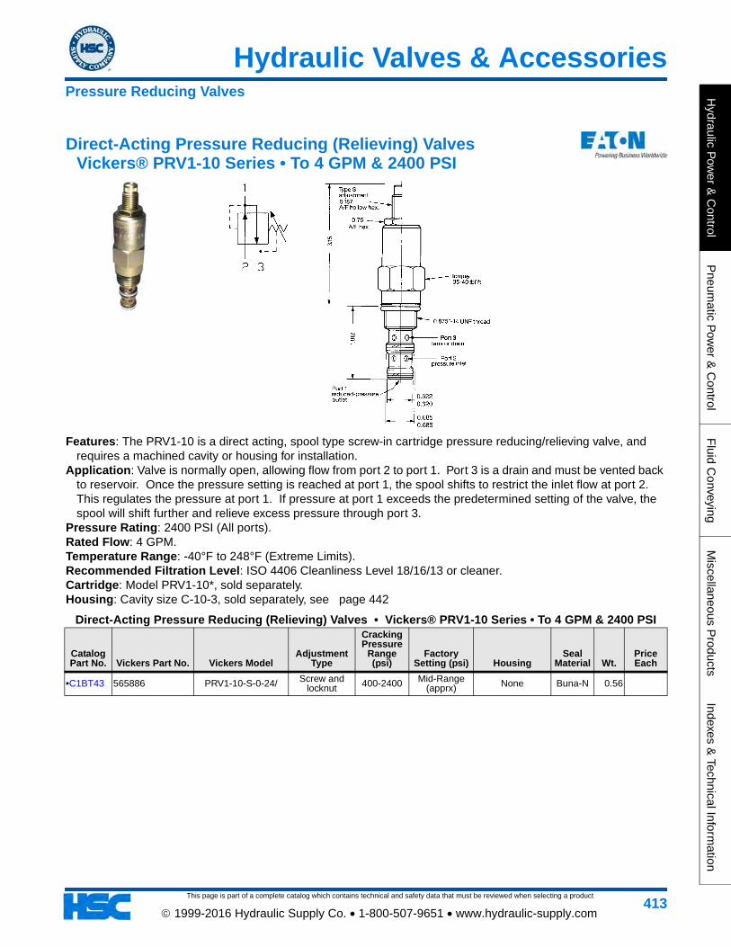
Hydraulic Valves & Accessories
This page is part of a complete catalog which contains technical and safety data that must be reviewed when selecting a product
Hydraulic P
ower &
Control
Pneum
atic Pow
er & C
ontrolF
luid Conveying
Miscellaneous P
roductsIndexes &
Technical Information
413 1999-2016 Hydraulic Supply Co. • 1-800-507-9651 • www.hydraulic-supply.com
Direct-Acting Pressure Reducing (Relieving) Valves Vickers® PRV1-10 Series • To 4 GPM & 2400 PSI
Features: The PRV1-10 is a direct acting, spool type screw-in cartridge pressure reducing/relieving valve, and requires a machined cavity or housing for installation.
Application: Valve is normally open, allowing flow from port 2 to port 1. Port 3 is a drain and must be vented back to reservoir. Once the pressure setting is reached at port 1, the spool shifts to restrict the inlet flow at port 2. This regulates the pressure at port 1. If pressure at port 1 exceeds the predetermined setting of the valve, the spool will shift further and relieve excess pressure through port 3.
Pressure Rating: 2400 PSI (All ports). Rated Flow: 4 GPM. Temperature Range: -40°F to 248°F (Extreme Limits). Recommended Filtration Level: ISO 4406 Cleanliness Level 18/16/13 or cleaner. Cartridge: Model PRV1-10*, sold separately. Housing: Cavity size C-10-3, sold separately, see page 442
Direct-Acting Pressure Reducing (Relieving) Valves • Vickers® PRV1-10 Series • To 4 GPM & 2400 PSI
Catalog Part No. Vickers Part No. Vickers Model
Adjustment Type
Cracking Pressure
Range (psi)
Factory Setting (psi) Housing
Seal Material Wt.
Price Each
•C1BT43 565886 PRV1-10-S-0-24/ Screw and locknut 400-2400 Mid-Range
(apprx) None Buna-N 0.56
Pressure Reducing Valves

This page is part of a complete catalog which contains technical and safety data that must be reviewed when selecting a product
Hydraulic Valves & Accessories
Hyd
raul
ic P
ower
& C
ontr
olP
neum
atic
Pow
er &
Con
trol
Flu
id C
onve
ying
Mis
cella
neou
s P
rodu
cts
Inde
xes
& T
echn
ical
Info
rmat
ion
414 1999-2016 Hydraulic Supply Co. • 1-800-507-9651 • www.hydraulic-supply.com
Pilot-Operated Pressure Reducing (Relieving) Valves Vickers® PRV2-10 Series • To 10 GPM & 3500 PSI
Features: The PRV2-10 is a pilot operated, spool type screw-in cartridge pressure reducing/relieving valve, and requires a machined cavity or housing for installation.
Application: This valve is normally open, allowing flow from port 2 to port 1. Port 3 is a drain and must be vented back to reservoir. Once the pressure setting is reached at port 1, the spool shifts to restrict the inlet flow at port 2. This regulates the pressure at port 1. If pressure at port 1 exceeds the predetermined setting of the valve, the spool will shift further and relieve excess pressure through port 3.
Pressure Rating: 3500 PSI All ports (CAUTION: Pressures over 3000 PSI require steel housing). Rated Flow: 10 GPM. Temperature Range: -40°F to 248°F (Extreme Limits). Recommended Filtration Level: ISO 4406 Cleanliness Level 18/16/13 or cleaner. Cartridge: Model PRV2-10*, sold separately. Housing: Cavity size C-10-3, sold separately, see page 442
Pilot-Operated Pressure Reducing (Relieving) Valves • Vickers® PRV2-10 Series • To 10 GPM & 3500 PSI
Catalog Part No. Vickers Part No. Vickers Model
Adjustment Type
Cracking Pressure
Range (psi)
Factory Setting (psi) Housing
Seal Material Wt.
Price Each
•C1ZZ80 02-170743 PRV2-10-S-0-35/25 Screw and locknut 250-3500 2500 None Buna-N 0.20
Housing Types: Aluminum STD (Standard light-duty aluminum 3000 psi maximum). Aluminum FR (Fatigue-rated aluminum 3000 psi maximum). Steel (Fatigue-rated Steel 5000 psi maximum).
Pressure Reducing Valves

Hydraulic Valves & Accessories
This page is part of a complete catalog which contains technical and safety data that must be reviewed when selecting a product
Hydraulic P
ower &
Control
Pneum
atic Pow
er & C
ontrolF
luid Conveying
Miscellaneous P
roductsIndexes &
Technical Information
415 1999-2016 Hydraulic Supply Co. • 1-800-507-9651 • www.hydraulic-supply.com
Pilot-Operated Pressure Reducing (Relieving) Valves Vickers® PRV2-16 Series • To 40 GPM & 5000 PSI
Features: The PRV2-16 is a pilot operated, spool type screw-in cartridge pressure reducing/relieving valve, and requires a machined cavity or housing for installation.
Application: This valve is normally open, allowing flow from port 2 to port 1. Port 3 is a drain and must be vented back to reservoir. Once the pressure setting is reached at port 1, the spool shifts to restrict the inlet flow at port 2. This regulates the pressure at port 1. If pressure at port 1 exceeds the predetermined setting of the valve, the spool will shift further and relieve excess pressure through port 3.
Pressure Rating: 5000 PSI All ports (CAUTION: Pressures over 3000 PSI require steel housing). Rated Flow: 40 GPM Temperature Range: -40°F to 248°F Recommended Filtration Level: ISO 4406 Cleanliness Level 18/16/13 or cleaner. Cartridge: Model PRV2-16*, sold separately. Housing: Cavity size C-16-3, sold separately, see page 442
Pilot-Operated Pressure Reducing (Relieving) Valves • Vickers® PRV2-16 Series • To 40 GPM & 5000 PSI
Catalog Part No. Vickers Part No. Vickers Model
Adjustment Type
Cracking Pressure
Range (psi)
Factory Setting (psi) Housing
Seal Material Wt.
Price Each
C1MG59 566376 PRV2 16 S 0 60 Screw 1000-6000 3500 None Buna-N 0.89
Pressure Reducing Valves

This page is part of a complete catalog which contains technical and safety data that must be reviewed when selecting a product
Hydraulic Valves & Accessories
Hyd
raul
ic P
ower
& C
ontr
olP
neum
atic
Pow
er &
Con
trol
Flu
id C
onve
ying
Mis
cella
neou
s P
rodu
cts
Inde
xes
& T
echn
ical
Info
rmat
ion
416 1999-2016 Hydraulic Supply Co. • 1-800-507-9651 • www.hydraulic-supply.com
3-Port Direct-Acting Relief Valves Brand RL Series • To 20 GPM
Features: In-line mounting. Precision built. Hardened, replaceable seat. Adjustment Style: Adjustment screw underneath removable cap. Maximum Operating Pressure: 3000 PSI. Maximum Flow Rate: 20 GPM.
3-Port Direct-Acting Relief Valves • Brand RL Series • To 20 GPMCatalog Part No. Brand Model Adjustment Range (psi) Pressure Port Tank Port Wt.
Price Each
•C1DB34 RL-50 150-3000 1/2 NPT 1/2 NPT 2.67
•C1DK23 RL-75 150-3000 3/4 NPT 1/2 NPT 2.30
Relief Valves • Direct-Acting Ball Type

Hydraulic Valves & Accessories
This page is part of a complete catalog which contains technical and safety data that must be reviewed when selecting a product
Hydraulic P
ower &
Control
Pneum
atic Pow
er & C
ontrolF
luid Conveying
Miscellaneous P
roductsIndexes &
Technical Information
417 1999-2016 Hydraulic Supply Co. • 1-800-507-9651 • www.hydraulic-supply.com
Panel Mount Direct-Acting Relief Valves Vickers® C-175 • To 3 GPM
Features: Panel mounting. Typically used to remotely control a “ventable” relief valve. Adjustment Style: Knob with jam nut. Maximum Operating Pressure: 3000 PSI. Maximum Flow Rate: 3 GPM.
Panel Mount Direct-Acting Relief Valves • Vickers® C-175 • To 3 GPMCatalog Part No.
Vickers Part No. Vickers Model
Adjustment Range (psi) Inlet Port Outlet Port
Seal Material Wt.
Price Each
C1BW85 631056 C-175-F-20 1500-3000 1/4 NPT 1/4 NPT Viton® 3.30
Cartridge Type Direct-Acting Relief Valves Vickers® RV1-10 Series • To 10 GPM
Features: Cartridge style (Requires a machined cavity or housing for installation). Continuous duty. Fast response. Low cost.
Adjustment Style: See table. Maximum Operating Pressure: 3000 PSI. Maximum Flow Rate: 10 GPM. Cartridge: Model RV1-10-*, sold separately. Housing: Cavity size C-10-2, sold separately, see page 441
Cartridge Type Direct-Acting Relief Valves • Vickers® RV1-10 Series • To 10 GPMCatalog Part No.
Vickers Part No.
Vickers Model (Cartridge Only) Adjustment Range (psi) Adjustment Type Seal Material Wt.
Price Each
•C1BT33 565563 RV1-10-S-0-30/ 500-3000 Screw Buna-N 0.53
Note: Housing not included.
Relief Valves • Direct-Acting Poppet Type

This page is part of a complete catalog which contains technical and safety data that must be reviewed when selecting a product
Hydraulic Valves & Accessories
Hyd
raul
ic P
ower
& C
ontr
olP
neum
atic
Pow
er &
Con
trol
Flu
id C
onve
ying
Mis
cella
neou
s P
rodu
cts
Inde
xes
& T
echn
ical
Info
rmat
ion
418 1999-2016 Hydraulic Supply Co. • 1-800-507-9651 • www.hydraulic-supply.com
Cartridge Type Direct-Acting Relief Valves Vickers® RV3-10 Series • To 20 GPM
Features: Cartridge style (Requires a machined cavity or housing for installation). Contamination tolerant. Fast response.
Adjustment Style: See table. Maximum Operating Pressure: 3600 PSI (CAUTION: Pressures over 3000 PSI require steel housing). Maximum Flow Rate: 20 GPM. Cartridge: Model RV3-10-*, sold separately. Housing: Cavity size C-10-2, sold separately, see page 441
Cartridge Type Direct-Acting Relief Valves • Vickers® RV3-10 Series • To 20 GPMCatalog Part No.
Vickers Part No. Vickers Model Adjustment Range (psi)
Adjustment Type Housing
Seal Material Wt.
Price Each
•C1ET93 566688 RV3-10-S-0-3/ 50-300 Screw None Buna-N 0.51
C1MX18 02-199334 RV3A-10-S-0-18/11 300-1800 (Set at 1100) Screw None Buna-N 0.53
•C1BT34 565568 RV3-10-S-0-36/ 600-3600 Screw None Buna-N 0.53
Housing Types: Aluminum STD (Standard light-duty aluminum 3000 psi maximum). Aluminum FR (Fatigue-rated aluminum 3000 psi maximum). Steel (Fatigue-rated Steel 5000 psi maximum).
RV3A: 1/2 thickness back-up ring on each side of o-ring (for cross port relief applications.
Relief Valves • Direct-Acting Differential Poppet Type

Hydraulic Valves & Accessories
This page is part of a complete catalog which contains technical and safety data that must be reviewed when selecting a product
Hydraulic P
ower &
Control
Pneum
atic Pow
er & C
ontrolF
luid Conveying
Miscellaneous P
roductsIndexes &
Technical Information
419 1999-2016 Hydraulic Supply Co. • 1-800-507-9651 • www.hydraulic-supply.com
Cartridge Type Direct-Acting Relief Valves Vickers® RV3-16 Series • To 80 GPM
Features: Cartridge style (Requires a machined cavity or housing for installation). Contamination tolerant. Fast response.
Adjustment Style: See table. Maximum Operating Pressure: 5000 PSI (CAUTION: Pressures over 3000 PSI require steel housing). Maximum Flow Rate: 80 GPM. Cartridge: Model RV3-16-*, sold separately. Housing: Cavity size C-16-2, sold separately, see page 441
Cartridge Type Direct-Acting Relief Valves • Vickers® RV3-16 Series • To 80 GPMCatalog Part No.
Vickers Part No.
Vickers Model (Cartridge Only) Adjustment Range (psi) Adjustment Type Seal Material Wt.
Price Each
•C1EN53 565569 RV3-16-S-0-35/ 1200-3500 Screw Buna-N 1.63
Note: Housing not included.
Relief Valves • Direct-Acting Differential Poppet Type

This page is part of a complete catalog which contains technical and safety data that must be reviewed when selecting a product
Hydraulic Valves & Accessories
Hyd
raul
ic P
ower
& C
ontr
olP
neum
atic
Pow
er &
Con
trol
Flu
id C
onve
ying
Mis
cella
neou
s P
rodu
cts
Inde
xes
& T
echn
ical
Info
rmat
ion
420 1999-2016 Hydraulic Supply Co. • 1-800-507-9651 • www.hydraulic-supply.com
Cartridge Type Pilot-Operated Poppet Type Relief Valves Vickers® RV2-10 Series • To 30 GPM
Features: Cartridge style (Requires a machined cavity or housing for installation). Ideal for use as a service line relief where anti-cavitation make-up is required.
Adjustment Style: See table. Maximum Operating Pressure: 5000 PSI (CAUTION: Pressures over 3000 PSI require steel housing). Rated Flow Range: 3 to 30 GPM. Cartridge: Model RV2-10-*, sold separately. Housing: Cavity size C-10-2, sold separately, see page 441
Cartridge Type Pilot-Operated Poppet Type Relief Valves • Vickers® RV2-10 Series • To 30 GPMCatalog Part No.
Vickers Part No. Vickers Model Adjustment Range (psi)
Adjustment Type Housing
Seal Material Wt.
Price Each
•C1FA75 566212 RV2-10-S-0-35/ 250-3500 Screw None Buna-N 0.53
Housing Types: Aluminum STD (Standard light-duty aluminum 3000 psi maximum). Aluminum FR (Fatigue-rated aluminum 3000 psi maximum). Steel (Fatigue-rated Steel 5000 psi maximum).
Relief Valves • Pilot-Operated Poppet Type

Hydraulic Valves & Accessories
This page is part of a complete catalog which contains technical and safety data that must be reviewed when selecting a product
Hydraulic P
ower &
Control
Pneum
atic Pow
er & C
ontrolF
luid Conveying
Miscellaneous P
roductsIndexes &
Technical Information
421 1999-2016 Hydraulic Supply Co. • 1-800-507-9651 • www.hydraulic-supply.com
Cartridge Type Pilot-Operated Spool Type Relief Valves Vickers® RV5-10 Series • To 30 GPM
Features: Cartridge style (Requires a machined cavity or housing for installation). Smooth and quiet. Continuous duty.
Adjustment Style: See table. Maximum Operating Pressure: 5000 PSI (CAUTION: Pressures over 3000 PSI require steel housing). Maximum Flow Rate: 30 GPM. Cartridge: Model RV5-10-*, sold separately. Housing: Cavity size C-10-2, sold separately, see page 441
Cartridge Type Pilot-Operated Spool Type Relief Valves • Vickers® RV5-10 Series • To 30 GPMCatalog Part No.
Vickers Part No. Vickers Model Adjustment Range (psi)
Adjustment Type Housing
Seal Material Wt.
Price Each
•C1FM79 02-164222 RV5-10-S-0-20/12 100-2000 (Set at 1200) Screw None Buna-N 0.51
C1KK46 566246 RV5-10-S-0-35/ 250-3500 Screw None Buna-N 0.51
C1MX11 02-180537 RV5-10-S-0-35/14 250-3500 (Set at 1400) Screw None Buna-N 0.51
C1AD24 02-164723 RV5-10-S-0-35/14.5 250-3500 (Set at 1450) Screw None Buna-N 0.51
C1FQ46 02-164209 RV5-10-S-0-35/15 250-3500 (Set at 1500) Screw None Buna-N 0.53
C1MW96 02-164733 RV5-10-I-0-35/30 250-3500 (Set at 3000) Internal None Buna-N 0.51
C1MW94 02-163944 RV5-10-F-0-35/30 250-3500 (Set at 3000) Factory set None Buna-N 0.51
•C1BT35 565572 RV5-10-S-0-50/ 500-5000 Screw None Buna-N 0.53
Housing Types: Aluminum STD (Standard light-duty aluminum 3000 psi maximum). Aluminum FR (Fatigue-rated aluminum 3000 psi maximum). Steel (Fatigue-rated Steel 5000 psi maximum).
Relief Valves • Pilot-Operated Spool Type

This page is part of a complete catalog which contains technical and safety data that must be reviewed when selecting a product
Hydraulic Valves & Accessories
Hyd
raul
ic P
ower
& C
ontr
olP
neum
atic
Pow
er &
Con
trol
Flu
id C
onve
ying
Mis
cella
neou
s P
rodu
cts
Inde
xes
& T
echn
ical
Info
rmat
ion
422 1999-2016 Hydraulic Supply Co. • 1-800-507-9651 • www.hydraulic-supply.com
Cartridge Type Pilot-Operated Spool Type Relief Valves Eaton 1VR200 Series • To 52 GPM
Features: This is a ventable, internally pilot operated relief valve designed to limit pressure in a system. Good for continuous duty and accurate pressure control with constant or varying flows. The vent feature can be used with remote pilot section for a two-pressure system or to allow manual or remote ‘unloading’ of the pump.
Maximum Operating Pressure: 5000 PSI (CAUTION: Pressures over 3000 PSI require steel housing). Maximum Flow Rate: 52 GPM Cartridge: Model 1VR200, sold separately Housing: Cavity size A16102, sold separately, see page 442
Cartridge Type Pilot-Operated Spool Type Relief Valves • Eaton 1VR200 Series • To 52 GPMCatalog Part No. Eaton Part No. Eaton Model
Adjustement Range (psi)
Adjustment Type Housing
Seal Material Wt.
Price Each
C1LX29 407AA00011A 1VR200P20S 145-3045 Screw None Nitrile 1.60
C1KK30 407AA00046A 1VR250P16T20S 145-3045 Screw SAE-16 ports Nitrile 3.20
Cartridge Type Pilot-Operated Relief Valves Vickers® RV5-16 Series • To 80 GPM
Features: Cartridge style (Requires a machined cavity or housing for installation). Smooth and quiet. Continuous duty.
Adjustment Style: See table. Maximum Operating Pressure: 6000 PSI (CAUTION: Pressures over 3000 PSI require steel housing). Maximum Flow Rate: 80 GPM. Cartridge: RV5-16-* sold separately. Housing: Cavity C-16-2, sold separately, see page 441
Cartridge Type Pilot-Operated Relief Valves • Vickers® RV5-16 Series • To 80 GPMCatalog Part No.
Vickers Part No. Vickers Model Adjustment Range (psi)
Adjustment Type Housing
Seal Material Wt.
Price Each
•C1EN56 565854 RV5-16-S-0-30/ 500-3000 Screw None Buna-N 0.79
C1MW95 02-164165 RV5-16-S-0-30/22 500-3000 (Set at 2200) Screw None Buna-N 0.79
Housing Types: Aluminum STD (Standard light-duty aluminum 3000 psi maximum). Aluminum FR (Fatigue-rated aluminum 3000 psi maximum). Steel (Fatigue-rated Steel 5000 psi maximum).
Relief Valves • Pilot-Operated Spool Type

Hydraulic Valves & Accessories
This page is part of a complete catalog which contains technical and safety data that must be reviewed when selecting a product
Hydraulic P
ower &
Control
Pneum
atic Pow
er & C
ontrolF
luid Conveying
Miscellaneous P
roductsIndexes &
Technical Information
423 1999-2016 Hydraulic Supply Co. • 1-800-507-9651 • www.hydraulic-supply.com
3-Port Pilot-Operated Relief Valves Vickers® CT & CS Series • To 60 GPM & 120 GPM
Features: In-line mounting. Gauge port. Ventable. Smooth and quiet. Continuous duty. Adjustment Style: Adjustment knob with locking nut. Maximum Operating Pressure: 3000 PSI. Maximum Flow Rate: Standard Models: 60 gpm (3/4 & -12 size), 120 gpm (1-1/4 & -20 size). High Flow Models:
90 gpm (3/4 & -12 size), 180 gpm (1-1/4 & -20 size).
3-Port Pilot-Operated Relief Valves • Vickers® CT & CS Series • To 60 GPM & 120 GPM
Catalog Part No.
Vickers Part No.
Vickers Model
Adj. Range (psi) Inlet Port
Outlet Port Gauge Port Vent Port
Seal Matl.
A (in)
B (in) Wt.
Price Each
C1BW11 590536 CT-06-B-50 125-1000 3/4 NPT 3/4 NPT 7/16-20 St.Thd. O-Ring
9/16-18 St.Thd. O-Ring Viton® 5.64 3.76 8.59
•C1BW12 590538 CT-06-C-50 500-2000 3/4 NPT 3/4 NPT 7/16-20 St.Thd. O-Ring
9/16-18 St.Thd. O-Ring Viton® 5.64 3.76 8.57
•C1BW13 590540 CT-06-F-50 1500-3000 3/4 NPT 3/4 NPT 7/16-20 St.Thd. O-Ring
9/16-18 St.Thd. O-Ring Viton® 5.64 3.76 8.66
•C1BV99 590283 CT-10-F-30 1500-3000 1-1/4 NPT 1-1/4 NPT 7/16-20 St.Thd. O-Ring
9/16-18 St.Thd. O-Ring Viton® 6.18 4.88 14.58
Relief Valves • Pilot-Operated Spool Type

This page is part of a complete catalog which contains technical and safety data that must be reviewed when selecting a product
Hydraulic Valves & Accessories
Hyd
raul
ic P
ower
& C
ontr
olP
neum
atic
Pow
er &
Con
trol
Flu
id C
onve
ying
Mis
cella
neou
s P
rodu
cts
Inde
xes
& T
echn
ical
Info
rmat
ion
424 1999-2016 Hydraulic Supply Co. • 1-800-507-9651 • www.hydraulic-supply.com
Subplate/Manifold Mount Pilot-Operated Relief Valves Vickers® CG2V-6/8 & CG5V-6/8 Series • To 106 GPM
Features: Close matching to application requirements from choice of four adjustment control ranges covering 44 to 5000 psi • Electrical on/off load from solenoid controlled models • Remote parallel control by other pilot valves connected to “vent” port • High machine productivity resulting from full system flow being available for work output until system pressure is very close to valve setting • Pressure override optimized without detriment to other performance parameters • Excellent repeatability and stable performance from cartridge-type design of mainstage parts • Low off-load power wastage • International mounting interfaces • Low installed cost and space requirement from high power/size ratios (more than double that of many conventional designs).
Maximum Operating Pressure: 5000 PSI ports P & X. Port T 1500 PSI for CG5V models, 5000 PSI for CG2V models.
Maximum Flow Rate: 53 GPM (Size 6 models), 106 GPM (Size 8 models). Temperature Range: -4°F to 158°F (petroleum oil). Recommended Filtration Level: ISO 4406 Cleanliness Level 19/17/14 or cleaner. Solenoid Connectors: page 446 (Required on models that use DIN 43650 connectors).
Subplate/Manifold Mount Pilot-Operated Relief Valves • Vickers® CG2V-6/8 & CG5V-6/8 Series • To 106 GPM
Catalog Part No.
Vickers Part No. Vickers Model
Mounting (ISO 6264) Function Features Wt.
Price Each
C1JM56 615027 CG2V-8BW-10 Size 8 (AS-08-2-A) Relief 44-1000 PSI Adjustment Range, Screw
Adjustment with Locknut 9.70
C1KY85 02-156983 CG5V-8GW-D-M-U-B6-11 Size 8 (AS-08-2-A) Relief
44-5000 PSI Adjustment Range, Screw Adjustment with Locknut, 110V AC 50
Hz/120V AC 60 Hz Electrical loading/unloading, ISO 4400 (DIN 43650)
electrical connection
Note: ISO 4400 (DIN 43650) female connector to be supplied by user. See page 446
Relief Valves • Pilot-Operated Spool Type

Hydraulic Valves & Accessories
This page is part of a complete catalog which contains technical and safety data that must be reviewed when selecting a product
Hydraulic P
ower &
Control
Pneum
atic Pow
er & C
ontrolF
luid Conveying
Miscellaneous P
roductsIndexes &
Technical Information
425 1999-2016 Hydraulic Supply Co. • 1-800-507-9651 • www.hydraulic-supply.com
Guided Piston Relief Valves Fulflo V Series with Threaded Ports
Application: The sliding piston concept and internal design contours of FULFLO valves provide unique flow and stability characteristics for reliable performance without chatter. Unlike ordinary direct acting relief valves, FULFLO guided piston valves are less responsive to transient pressure surges thereby eliminating the tendency to pound, squeal or chatter. Quiet, stable, efficient performance is assured in both load regulation and system protection applications. FULFLO valves operate effectively with all types of liquids in the full range of viscosities including hydraulic oils, water, solvents and chemicals. Since the FULFLO relief valve is a flow-modulating device, pressure flow characteristics are completely different from spring loaded poppet or ball check valves. Both types remain substantially tight up to cracking pressure. When this pressure is exceeded, the “conventional” valve pops open with a pressure drop at very low flow and an exponential pressure rise as the flow increases. In contrast the FULFLO valve causes a pressure rise, over-pressure, as soon as flow starts; pressure increases almost proportionally with flow. Springs and areas on FULFLO valves are carefully designed to minimize this over-pressure.
Note: FULFLO valves are not designed to be positive shut off, and will pass a minimal amount of leakage before the set pressure. FULFLO valves are NOT designed for use with air, gas or steam.
Performance Charts: page 700
Guided Piston Relief Valves • Fulflo V Series with Threaded Ports
Catalog Part No. Fulflo Model Ports
Rated Capacity
(GPM) Body Spring Piston O-RingOther
FeaturesAA (in)
BB (in)
CC (in)
DD (in) Wt.
Price Each
C1FG22 VJ-5-YS-190PSI 1 NPT 25 Cast Iron
507-YS (150-350
PSI)
Hardened Steel Buna-N 8.22 2.28 2.28 2.06 5.37
C1EZ82 VJ-7-XS 1-1/2 NPT 80 Cast Iron
707-XS (60-175
PSI)
Hardened Steel Buna-N 11.06 2.69 2.69 2.88 13.49
Relief Valves • Guided Piston Type

This page is part of a complete catalog which contains technical and safety data that must be reviewed when selecting a product
Hydraulic Valves & Accessories
Hyd
raul
ic P
ower
& C
ontr
olP
neum
atic
Pow
er &
Con
trol
Flu
id C
onve
ying
Mis
cella
neou
s P
rodu
cts
Inde
xes
& T
echn
ical
Info
rmat
ion
426 1999-2016 Hydraulic Supply Co. • 1-800-507-9651 • www.hydraulic-supply.com
Vickers® Sandwich Valves • NFPA-D03 Size Aluminum Valve Bodies • Pressures to 3000 PSI
Features: • Reduces System Space Requirements • Reduce Cost • Versatile and Easy to Install • Linking and blanking plates are available to facilitate a variety of circuit designs and flexibility in applying these valves • Rugged and Reliable • Cartridges are accessible without removing valves from an assembled stack. • Housings are assembled in a kit containing a locating pin, all necessary plugs and standard Viton seals.Construction: Aluminum (Housings, Blanking Plates, Linking Plates and Spacer Plates).
Valve Cartridges: Screw-in valve cartridges.Maximum Operating Pressure: 3000 PSI.Temperature Range & Recommended Filtration: Refer to information on cartridge valve(s) selected.Seal Material: Viton® o-rings are standard and are included along with locating pin to mount housings and plates
to the NFPA-D03 surface (4ea -012 size o-rings).Bolt Kits: 10-24 grade 8 socket head cap screws lubricated and torqued to 63-80 lb.in. Bolt kits on page 440Stud Rod & Nut Kits: Kit number 02-184932: 4ea 10-24 x 7 inch stud rods and stud nuts. Kit number 02-184933:
4ea 10-24 x 12 inch stud rods and stud nuts. Stud rods/nuts should be torqued to 40-53 lb.in. with threads lubricated.
A323W Housing Kit
Typical Cartridges: Counterbalance valves on A & B cross-piloted, 1CE30 Series page 267. Pilot operated check valves on A & B cross piloted, 4CK30 page 258
A323W Housing Kit
Catalog Part No. Vickers Part No.
Vickers Model Cavity Qty & Size Typical Cartridges
Housing Height
(in) Wt.Price Each
C1HY33 02-185347 A323W 2ea C-10-3S 1CE30 (Counterbalance Valve), 4CK30 (Pilot-operated check valves) 1.70 1.21
Sandwich Valves • NFPA Size D03 • ISO 4401 Size 03Vickers Sandwich Valves

Hydraulic Valves & Accessories
This page is part of a complete catalog which contains technical and safety data that must be reviewed when selecting a product
Hydraulic P
ower &
Control
Pneum
atic Pow
er & C
ontrolF
luid Conveying
Miscellaneous P
roductsIndexes &
Technical Information
427 1999-2016 Hydraulic Supply Co. • 1-800-507-9651 • www.hydraulic-supply.com
Single Selector Valves Cross VS Series
Cross VS Series hydraulic selector valves are manually operated, spool type, 3-way 2-position valves featuring cast-in metering notches for smooth operation. They provide an economical method of diverting flow to either of two hydraulic circuits and are available with a variety of actuators.
Construction: High tensile strength cast iron body. Ground, plated and polished steel spool. Buna-N seals. Available Options: Actuator location port A or port B side. Knob, clevis or plain actuator (VS2 models). Knob,
clevis, plain, handle or hydraulic pilot actuator (VS4 models). Manual spool action (VS2 models). Manual, spring return, 2-position detent or hydraulic pilot spool action (VS4 models). Front, bottom or both front and bottom inlet port location. 1/2 NPT or SAE-8 ports (VS2 models). 3/4 NPT, SAE-12 or SAE-16 ports (VS4 models).
Single Selector Valves • Cross VS Series
Catalog Part No. Cross Model Port Size
Nominal Flow
Rating (GPM)
Maximum Operating
Pressure (psi) Features Dimensions (in) Wt.Price Each
•C1GK85 VS2BKLF2 1/2 NPT 20 2500
Standard Knob actuator port B side. Standard
Manual spool positioning. Standard front inlet port
location.
A=2.12 B=1.53 C=0.34 D=3.25 E=1.19 F=1.62 G=2.25 H=1.00 J=0.31
K=5.33
3.24
•C1GK86 VS4BKLF6 3/4 NPT 40 2500
Standard Knob actuator port B side. Standard
Manual spool positioning. Standard front inlet port
location.
A=3.00 B=1.56 C=0.34 D=4.12 E=1.50 F=2.12 G=2.62 H=1.12 J=6.12
K=6.12
7.19
•C1GK87 VS4BKLF9 SAE-16 40 2500
Standard Knob actuator port B side. Standard
Manual spool positioning. Standard front inlet port
location.
A=3.00 B=1.56 C=0.34 D=4.12 E=1.50 F=2.12 G=2.62 H=1.12 J=6.12
K=6.12
6.67
Catalog Part No. Part Number Description Wt.
Price Each
•C1FA47 1V1703 Valve Handle 0.28
•C1BR52 4Z4306 Handle Bracket 0.16
Selector Valves • Single, Double, 2-Wheel / 4-Wheel, Solenoid Operated

This page is part of a complete catalog which contains technical and safety data that must be reviewed when selecting a product
Hydraulic Valves & Accessories
Hyd
raul
ic P
ower
& C
ontr
olP
neum
atic
Pow
er &
Con
trol
Flu
id C
onve
ying
Mis
cella
neou
s P
rodu
cts
Inde
xes
& T
echn
ical
Info
rmat
ion
428 1999-2016 Hydraulic Supply Co. • 1-800-507-9651 • www.hydraulic-supply.com
Double Selector Valves Cross SD Series
Cross SD Series hydraulic selector valves are manually operated, spool type, 6-way 2-position valves featuring cast-in metering notches for smooth operation. They provide an economical method of diverting flow to two separate hydraulic circuits or providing various types of multiple system operations in combination with other valves.
Construction: High tensile strength cast iron body. Ground, plated and polished steel spool. Buna-N seals. Available Options: Actuator location port C or port D side. Knob, clevis, handle, plain or hydraulic pilot actuator.
Manual, spring return, 2-position detent or hydraulic pilot spool action. Selector or Series/Parallel spool type. SAE-8, SAE-12, SAE-16, 3/4 NPT or 1 NPT ports.
Double Selector Valves • Cross SD Series
Catalog Part No. Cross Model Port Size
Nominal Flow
Rating (GPM)
Maximum Operating
Pressure (psi) Features Wt.Price Each
•C1GK53 SD4BALA4 3/4 NPT 40 2500 Selector Spool. Optional Handle actuator port D side. Standard Manual spool positioning. 9.70
Catalog Part No. Part Number Description Wt.
Price Each
•C1FA47 1V1703 Valve Handle 0.28
•C1BR52 4Z4306 Handle Bracket 0.16
Selector Valves • Single, Double, 2-Wheel / 4-Wheel, Solenoid Operated

Hydraulic Valves & Accessories
This page is part of a complete catalog which contains technical and safety data that must be reviewed when selecting a product
Hydraulic P
ower &
Control
Pneum
atic Pow
er & C
ontrolF
luid Conveying
Miscellaneous P
roductsIndexes &
Technical Information
429 1999-2016 Hydraulic Supply Co. • 1-800-507-9651 • www.hydraulic-supply.com
2-Wheel / 4-Wheel Selector Valve Cross SD5 Series
The Cross SD5 2-wheel / 4-wheel selector valve has been specifically designed for use with hydrostatic transmissions and permits selection of either 2-wheel (transport mode) or 4-wheel (work mode) drive positions.
Specifications: Maximum working pressure: 5000 PSI. Maximum shock & surge pressure: 6000 PSI. Maximum flow capacity: 50 GPM.
Construction: High tensile strength cast iron body. Ground, plated & polished steel spool. Buna-N seals. Available Options: Ports - 1/2 NPT, SAE-8, SAE-12, SAE-16. Actuator - Handle, Knob, Clevis, Pilot, 12VDC
Solenoid. Application Note: When in 2-wheel drive, supercharge oil is supplied to the non-driving motors, preventing
cavitation. When operating in 2-wheel drive for long periods of time, it may be necessary to occasionally shift into 4-wheel drive in order to cool the non-driving wheel motors.
2-Wheel / 4-Wheel Selector Valve • Cross SD5 SeriesCatalog Part No. Cross Model
Actuator Location Actuator Option End Cap Option Spool Type Port Size Wt.
Price Each
C1EP17 SD5BUBA7 Port D Side Hydraulic Pilot Spring Return 2-Wheel / 4-Wheel
Selector SAE-16 10.00
Cross SD5 Series PartsCatalog Part No. Part Number Description Wt.
Price Each
•C1FA47 1V1703 Valve Handle 0.28
•C1BR52 4Z4306 Handle Bracket 0.16
Selector Valves • Single, Double, 2-Wheel / 4-Wheel, Solenoid Operated

This page is part of a complete catalog which contains technical and safety data that must be reviewed when selecting a product
Hydraulic Valves & Accessories
Hyd
raul
ic P
ower
& C
ontr
olP
neum
atic
Pow
er &
Con
trol
Flu
id C
onve
ying
Mis
cella
neou
s P
rodu
cts
Inde
xes
& T
echn
ical
Info
rmat
ion
430 1999-2016 Hydraulic Supply Co. • 1-800-507-9651 • www.hydraulic-supply.com
Solenoid-Operated Selector Valves Walvoil DFE Series
Available Ways: DFE052: 2-3-6-8-way. DFE20: 3-6-way. Nominal Flow Rating: DFE052: 16 GPM. DFE20: 37 GPM. Maximum Operating Pressure: 2900 PSI (without drain), 4600 PSI (with optional drain). Internal Leakage: DFE052: 0.43 in³/min maximum at 1450 PSI differential pressure. DFE020: 0.92 in³/min
maximum at 1450 PSI differential pressure. Fluid Temperature Range: -4°F to 176°F (standard Buna-N seals), -4°F to 212°F (optional Viton® seals). Ambient Temperature Range: -40°F to 140°F. Viscosity: 80 to 400 SSU Operating, 70 SSU Minimum, 1950 SSU Maximum. Maximum Level of Contamination: ISO 4406 19/16. Note: Performance data measured with mineral oil of 215 SSU viscosity at 104°F.
Solenoid-Operated Selector Valves • Walvoil DFE Series
Catalog Part No. Walvoil Model Ports
Nominal Flow
Rating Spool TypeSpool
Positioner CoilOther
Features Wt.Price Each
C1KL99 FVL12A270034 6 16 GPM 6-way, 2-pos, closed crossover
Spring return to position 1 12VDC 4.40
Selector Valves • Single, Double, 2-Wheel / 4-Wheel, Solenoid Operated

This page is part of a complete catalog which contains technical and safety data that must be reviewed when selecting a product
Hydraulic Valves & Accessories
Hydraulic P
ower &
Control
Pneum
atic Pow
er & C
ontrolF
luid Conveying
Miscellaneous P
roductsIndexes &
Technical Information
431 1999-2016 Hydraulic Supply Co. • 1-800-507-9651 • www.hydraulic-supply.com
Slip-In Cartridge Valves To ISO 7368 (DIN 24342)
Detailed information on the entire line of Vickers® Slip-In Cartridge Valves can be found in Literature ID # 5043.00/EN/0499/A. Please contact us for application assistance or to request a copy of this publication.
Slip-In Cartridge Valves • To ISO 7368 (DIN 24342)Catalog Part No.
Vickers Part No. Vickers Model Key Description Wt. Price Each
C1LX54 847AN00007A CVI-25-D10-H-50 D10 Relief Insert, 1:1 Area Ratio, Size 25, 485 PSI Cracking Pressure 0.96
Slip-In Cartridge Valves

This page is part of a complete catalog which contains technical and safety data that must be reviewed when selecting a product
Hydraulic Valves & Accessories
Hyd
raul
ic P
ower
& C
ontr
olP
neum
atic
Pow
er &
Con
trol
Flu
id C
onve
ying
Mis
cella
neou
s P
rodu
cts
Inde
xes
& T
echn
ical
Info
rmat
ion
432 1999-2016 Hydraulic Supply Co. • 1-800-507-9651 • www.hydraulic-supply.com
Vickers® SystemStak™ Valves • NFPA-D03 Size Flows to 16 GPM • Pressures to 4500 PSI
Features: Save space & installation time. Reduce potential leaks. Standard interface. Rugged design with large flow passages, high pressure and high flow ratings.Construction: Ductile iron (spheroidal graphite) body (NFPA fatigue proof rated at 4500 PSI). Hardened steel internal parts. Aluminum nameplates. Standard Viton® seals.Available Functions: Relief, Counterbalance, Sequence, Pressure Reducing, Direct Check, Pilot-Operated Check, Flow Control.Maximum Operating Pressure: 4500 PSI.Ambient Temperature Limits: -4°F to 176°F.Fluid Temperature Limits: Petroleum Oil: -4°F to 176°F. Water Base Fluids: 50°F to 129°F.Filtration Requirements: Up to 3000 PSI: ISO level 20/16. Over 3000 PSI: ISO level 18/14.Bolt Kits: 10-24 grade 8 socket head cap screws lubricated and torqued to 63-80 lb.in. Bolt kits on page 440
Dimensions & Technical Information: page 701Size D03 Subplates & Manifolds: page 450
Vickers® SystemStak™ Relief Valves NFPA-D03 • ISO 4401-03
General Description: These pilot-operated adjustable pressure relief valves limit the maximum pressure in the line(s) controlled by the integral relief valve elements. Pressure adjustment of screw & locknut or control knob (with or without keylock) are available.
Stacking Height to add for Bolt Length: 1.57 inches.
Vickers® SystemStak™ Relief Valves • NFPA-D03 • ISO 4401-03
Catalog Part No.
Vickers Part No. Vickers Model Key Type Function
Pressure Adjustment Range (psi)
Adjustment Type
Gauge Port Wt.
Price Each
C1JA16 694419 DGMC-3-PT-CW-41 A Single Relief P to T 145-2900 Screw &
Locknut No 2.90
C1DZ90 871702 DGMC2-3-AT-GW-BT-GW-41 C Dual Relief A to T, B to T 75-4500 Screw & Locknut No 3.00
C1JS91 02-108133 DGMC-3-BT-GW-41 D Single Relief B to T 725-4500 Screw &
Locknut No 2.53
Stack Valves • NFPA Size D03 • ISO 4401 Size 03Vickers SystemStak™ Valves

This page is part of a complete catalog which contains technical and safety data that must be reviewed when selecting a product
Hydraulic Valves & Accessories
Hydraulic P
ower &
Control
Pneum
atic Pow
er & C
ontrolF
luid Conveying
Miscellaneous P
roductsIndexes &
Technical Information
433 1999-2016 Hydraulic Supply Co. • 1-800-507-9651 • www.hydraulic-supply.com
Vickers SystemStak™ Pressure Reducing Valves NFPA-D03 • ISO 4401-03
General Description: The flow path is normally open and is closed as the pilot pressure exceeds the setting of the valve. Excessive pressure in the reduced pressure line is prevented by a pressure relieving function. Pressure adjustment options of screw & locknut or control knob (with or without keylock) are available.
Stacking Height to add for Bolt Length: 1.57 inches.
Vickers SystemStak™ Pressure Reducing Valves • NFPA-D03 • ISO 4401-03
Catalog Part No.
Vickers Part No. Vickers Model Key Function
Pressure Adjustment Range (psi)
Adjustment Type
Adjuster Location
Gauge Port Wt.
Price Each
C1DZ89 870039 DGMX2-3-PP-BW-S-40 A Pressure Reduced in P Piloted from P 51-1000 Screw &
LocknutB Port End SAE-4 2.90
Vickers SystemStak™ Check Valves NFPA-D03 • ISO 4401-03
General Description: These valves allow free flow in one direction in the line in which the check valve element(s) is (are) located. Flow in the opposite direction is not possible. Stacking Height to add for Bolt Length: 1.57 inches.
Vickers SystemStak™ Check Valves • NFPA-D03 • ISO 4401-03
Catalog Part No.
Vickers Part No. Vickers Model Key Function
Cracking Pressure
(psi) Wt.Price Each
C1JL49 02-138605 DGMDC-3-Y-PM-41 A Check in P, Free Flow towards Work Port 36.0 2.08
Stack Valves • NFPA Size D03 • ISO 4401 Size 03Vickers SystemStak™ Valves

This page is part of a complete catalog which contains technical and safety data that must be reviewed when selecting a product
Hydraulic Valves & Accessories
Hyd
raul
ic P
ower
& C
ontr
olP
neum
atic
Pow
er &
Con
trol
Flu
id C
onve
ying
Mis
cella
neou
s P
rodu
cts
Inde
xes
& T
echn
ical
Info
rmat
ion
434 1999-2016 Hydraulic Supply Co. • 1-800-507-9651 • www.hydraulic-supply.com
Vickers SystemStak™ Pilot-Operated Check Valves NFPA-D03 • ISO 4401-03
General Description: These valves provide pilot-operated check functions in one or both work ports, with pilot pressure coming from the opposite side. An optional 10:1 decompression feature is available. Stacking Height to add for Bolt Length: 1.57 inches.
Vickers SystemStak™ Pilot-Operated Check Valves • NFPA-D03 • ISO 4401-03
Catalog Part No.
Vickers Part No. Vickers Model Key Function
Pilot Ratio
Cracking Pressure
(psi) Wt.Price Each
•C1BY42 694400 DGMPC-3-ABK-BAK-41 A Dual Pilot Check 3:1 14.5 2.28
•C1FF82 870024 DGMPC-3-ABK-41 B Single Pilot Check in A Piloted from B 3:1 14.5 2.13
Vickers SystemStak™ Flow Control Valves NFPA-D03 • ISO 4401-03
General Description: These valves regulate flow by means of an adjustable orifice which is not pressure compensated, and flow through the valve is entirely dependent upon pressure drop at any particular setting of the orifice. Single and Dual work port models with integral reverse flow checks are available in both meter-our and meter-in
styles. Single P port models are available without the reverse flow check. Stacking Height to add for Bolt Length: 1.57 inches.
Vickers SystemStak™ Flow Control Valves • NFPA-D03 • ISO 4401-03
Catalog Part No.
Vickers Part No. Vickers Model Key Function
Control Needle Type
Adjustment Type Wt.
Price Each
C1BY43 694412 DGMFN-3-Y-A2W-B2W-41 A Dual Meter Out of Work Ports Standard Screw & Locknut 2.41
Stack Valves • NFPA Size D03 • ISO 4401 Size 03Vickers SystemStak™ Valves

This page is part of a complete catalog which contains technical and safety data that must be reviewed when selecting a product
Hydraulic Valves & Accessories
Hydraulic P
ower &
Control
Pneum
atic Pow
er & C
ontrolF
luid Conveying
Miscellaneous P
roductsIndexes &
Technical Information
435 1999-2016 Hydraulic Supply Co. • 1-800-507-9651 • www.hydraulic-supply.com
Vickers® SystemStak™ Valves • NFPA-D05 Size Flows to 32 GPM • Pressures to 4500 PSI
Features: Save space & installation time. Reduce potential leaks. Standard interface. Rugged design with large flow passages, high pressure and high flow ratings.Construction: Ductile iron (spheroidal graphite) body (NFPA fatigue proof rated at 4500 PSI). Hardened steel internal parts. Aluminum nameplates. Standard Viton® seals.Available Functions: Relief, Counterbalance, Sequence, Pressure Reducing, Direct Check, Pilot-Operated Check, Flow Control.Maximum Operating Pressure: 4500 PSI.Fluid Temperature Limits: Dependent on type of valve (See limits in individual group information).Filtration Requirements: ISO level 19/17/14.Mounting Bolt Options: Size 05 SystemStak™ valves may be mounted with either bolt
extender kits or standard 1/4-20 grade 8 socket head cap screws. (Threads lubricated Bolt Extender torque is 100-130 lb. in. Threads lubricated standard socket head cap screw torque is 112 lb.in. maximum).
Bolt Extenders: page 440Bolt Kits: page 440Dimensions & Technical Information: page 706Size D05 Subplates & Manifolds: page 452
Vickers® SystemStak™ Relief Valves NFPA-D05 • ISO 4401-05
General Description: These two-stage valves limit system pressure by directing flow to tank or the opposite work port when system pressure reaches the valve setting. Pressure control may be obtained in A, B, A & B, or P port, and pilot flow may be internally or externally drained, depending on model type. Any
back pressure is additive to valve setting. Standard adjustment is a screw with locknut (other options available). External remote control/vent options are available.
Fluid Temperature Limits: 32°F to 180°F. Stacking Height: 1.97 inches (Single & Dual Reliefs), 2.36 inches (Crossover
Reliefs).
Vickers® SystemStak™ Relief Valves • NFPA-D05 • ISO 4401-05
Catalog Part No.
Vickers Part No. Vickers Model Key Type Function
Pressure Adjustment Range (psi)
Adjustment Type
Gauge Port Wt.
Price Each
C1HJ81 867315 DGMC-5-PT-GW-S-30 A Single Relief
Pressure Limited in P
Port60-4500 Screw &
Locknut SAE-4 7.17
Stack Valves • NFPA Size D05 • ISO 4401 Size 05Vickers SystemStak™ Valves
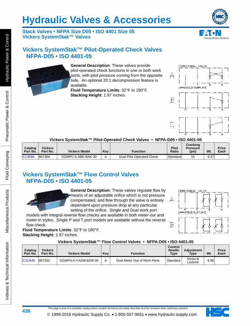
This page is part of a complete catalog which contains technical and safety data that must be reviewed when selecting a product
Hydraulic Valves & Accessories
Hyd
raul
ic P
ower
& C
ontr
olP
neum
atic
Pow
er &
Con
trol
Flu
id C
onve
ying
Mis
cella
neou
s P
rodu
cts
Inde
xes
& T
echn
ical
Info
rmat
ion
436 1999-2016 Hydraulic Supply Co. • 1-800-507-9651 • www.hydraulic-supply.com
Vickers SystemStak™ Pilot-Operated Check Valves NFPA-D05 • ISO 4401-05
General Description: These valves provide pilot-operated check functions in one or both work ports, with pilot pressure coming from the opposite side. An optional 20:1 decompression feature is available. Fluid Temperature Limits: 32°F to 180°F. Stacking Height: 1.97 inches.
Vickers SystemStak™ Pilot-Operated Check Valves • NFPA-D05 • ISO 4401-05
Catalog Part No.
Vickers Part No. Vickers Model Key Function
Pilot Ratio
Cracking Pressure
(psi) Wt.Price Each
C1JE98 867364 DGMPC-5-ABK-BAK-30 A Dual Pilot-Operated Check Standard 15 6.47
Vickers SystemStak™ Flow Control Valves NFPA-D05 • ISO 4401-05
General Description: These valves regulate flow by means of an adjustable orifice which is not pressure compensated, and flow through the valve is entirely dependent upon pressure drop at any particular setting of the orifice. Single and Dual work port
models with integral reverse flow checks are available in both meter-our and meter-in styles. Single P and T port models are available without the reverse flow check.
Fluid Temperature Limits: 32°F to 180°F. Stacking Height: 1.97 inches.
Vickers SystemStak™ Flow Control Valves • NFPA-D05 • ISO 4401-05
Catalog Part No.
Vickers Part No. Vickers Model Key Function
Control Needle Type
Adjustment Type Wt.
Price Each
C1CA45 867332 DGMFN-5-Y-A2W-B2W-30 A Dual Meter Out of Work Ports Standard Screw & Locknut 6.86
Stack Valves • NFPA Size D05 • ISO 4401 Size 05Vickers SystemStak™ Valves
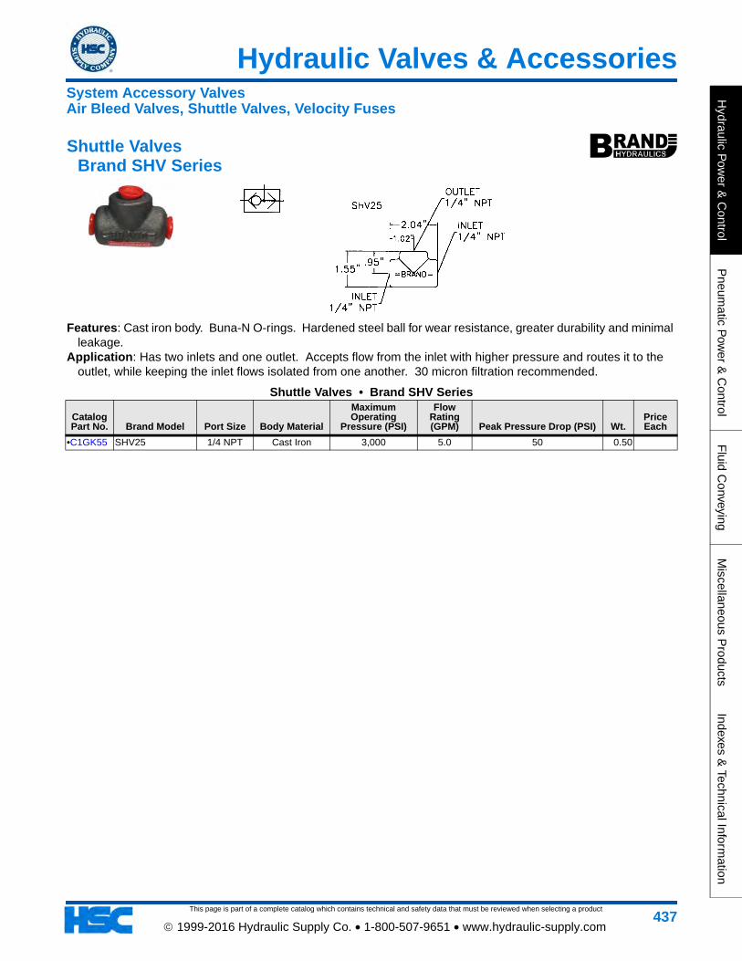
Hydraulic Valves & Accessories
This page is part of a complete catalog which contains technical and safety data that must be reviewed when selecting a product
Hydraulic P
ower &
Control
Pneum
atic Pow
er & C
ontrolF
luid Conveying
Miscellaneous P
roductsIndexes &
Technical Information
437 1999-2016 Hydraulic Supply Co. • 1-800-507-9651 • www.hydraulic-supply.com
Shuttle Valves Brand SHV Series
Features: Cast iron body. Buna-N O-rings. Hardened steel ball for wear resistance, greater durability and minimal leakage.
Application: Has two inlets and one outlet. Accepts flow from the inlet with higher pressure and routes it to the outlet, while keeping the inlet flows isolated from one another. 30 micron filtration recommended.
Shuttle Valves • Brand SHV Series
Catalog Part No. Brand Model Port Size Body Material
Maximum Operating
Pressure (PSI)
Flow Rating (GPM) Peak Pressure Drop (PSI) Wt.
Price Each
•C1GK55 SHV25 1/4 NPT Cast Iron 3,000 5.0 50 0.50
System Accessory ValvesAir Bleed Valves, Shuttle Valves, Velocity Fuses
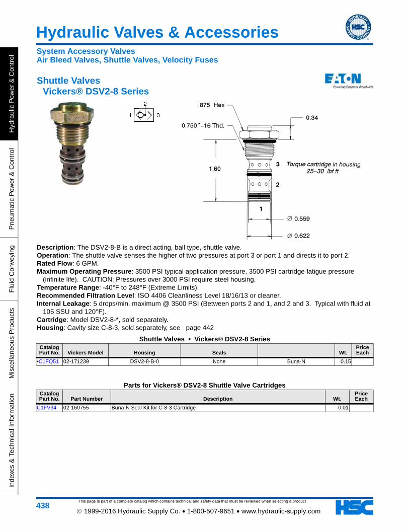
This page is part of a complete catalog which contains technical and safety data that must be reviewed when selecting a product
Hydraulic Valves & Accessories
Hyd
raul
ic P
ower
& C
ontr
olP
neum
atic
Pow
er &
Con
trol
Flu
id C
onve
ying
Mis
cella
neou
s P
rodu
cts
Inde
xes
& T
echn
ical
Info
rmat
ion
438 1999-2016 Hydraulic Supply Co. • 1-800-507-9651 • www.hydraulic-supply.com
Shuttle Valves Vickers® DSV2-8 Series
Description: The DSV2-8-B is a direct acting, ball type, shuttle valve. Operation: The shuttle valve senses the higher of two pressures at port 3 or port 1 and directs it to port 2. Rated Flow: 6 GPM. Maximum Operating Pressure: 3500 PSI typical application pressure, 3500 PSI cartridge fatigue pressure
(infinite life). CAUTION: Pressures over 3000 PSI require steel housing. Temperature Range: -40°F to 248°F (Extreme Limits). Recommended Filtration Level: ISO 4406 Cleanliness Level 18/16/13 or cleaner. Internal Leakage: 5 drops/min. maximum @ 3500 PSI (Between ports 2 and 1, and 2 and 3. Typical with fluid at
105 SSU and 120°F). Cartridge: Model DSV2-8-*, sold separately. Housing: Cavity size C-8-3, sold separately, see page 442
Shuttle Valves • Vickers® DSV2-8 SeriesCatalog Part No. Vickers Model Housing Seals Wt.
Price Each
•C1FQ51 02-171239 DSV2-8-B-0 None Buna-N 0.15
Parts for Vickers® DSV2-8 Shuttle Valve CartridgesCatalog Part No. Part Number Description Wt.
Price Each
C1FV34 02-160755 Buna-N Seal Kit for C-8-3 Cartridge 0.01
System Accessory ValvesAir Bleed Valves, Shuttle Valves, Velocity Fuses
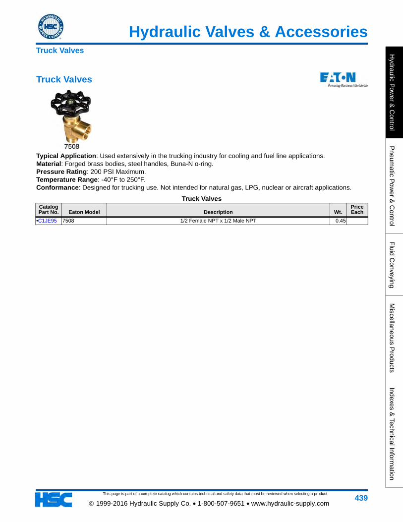
Hydraulic Valves & Accessories
This page is part of a complete catalog which contains technical and safety data that must be reviewed when selecting a product
Hydraulic P
ower &
Control
Pneum
atic Pow
er & C
ontrolF
luid Conveying
Miscellaneous P
roductsIndexes &
Technical Information
439 1999-2016 Hydraulic Supply Co. • 1-800-507-9651 • www.hydraulic-supply.com
Truck Valves
Typical Application: Used extensively in the trucking industry for cooling and fuel line applications. Material: Forged brass bodies, steel handles, Buna-N o-ring. Pressure Rating: 200 PSI Maximum. Temperature Range: -40°F to 250°F. Conformance: Designed for trucking use. Not intended for natural gas, LPG, nuclear or aircraft applications.
Truck ValvesCatalog Part No. Eaton Model Description Wt.
Price Each
•C1JE95 7508 1/2 Female NPT x 1/2 Male NPT 0.45
Truck Valves

This page is part of a complete catalog which contains technical and safety data that must be reviewed when selecting a product
Hydraulic Valves & Accessories
Hyd
raul
ic P
ower
& C
ontr
olP
neum
atic
Pow
er &
Con
trol
Flu
id C
onve
ying
Mis
cella
neou
s P
rodu
cts
Inde
xes
& T
echn
ical
Info
rmat
ion
440 1999-2016 Hydraulic Supply Co. • 1-800-507-9651 • www.hydraulic-supply.com
Valve Mounting Bolt Kits
Valve Mounting Bolt KitsCatalog Part No.
Vickers Part No. Vickers Model Bolt Qty Bolt Size Wt.
Price Each
•C1BW14 590716 BK590716 4 10-24 x 1-1/4 0.05
•C1CA49 870017 BK870017 4 10-24 x 2-3/4 0.10
•C1BQ65 466851 BK466851 4 10-24 x 3-1/2 0.12
C1BQ66 466853 BK466853 4 10-24 x 4-5/16 0.13
•C1BH34 255633 BKDG01-633 4 1/4-20 x 1-1/2 0.10
C1KK36 464125 BK464125M 4 M5 x 70 0.10
A: Bolt length in directional valve, blanking plate, crossover plate, etc. • DG4V-3 & DG4V-3S Valves: A = 0.86 inches • DG4S4-01 Valves: A = 1.13 inches • DG5S-8 & DG5V-8 Valves: A = 1.69 inches B: Height of intermediate valve stack, if any. C: Depth of thread engagement in subplate or manifold. • 10-24 Bolt Threads: 0.39 inch required engagement • 1/4-20 Bolt Threads: 0.37 inch required engagement • 1/2-13 Bolt Threads: 0.81 inch required engagement L: Required bolt length.
SystemStak™ Bolt Extender Kits (NFPA D05 Size Valves)
SystemStak™ Bolt Extender Kits (NFPA D05 Size Valves)Catalog Part No.
Vickers Part No.
Vickers Model
Extender Qty
SystemStak™ Valve Height (in) Wt.
Price Each
C1DX61 525744 BKE-4-50M 4 1.97 0.18
Bolt Kits & Bolt Extenders

This page is part of a complete catalog which contains technical and safety data that must be reviewed when selecting a product
Hydraulic Valves & Accessories
Hydraulic P
ower &
Control
Pneum
atic Pow
er & C
ontrolF
luid Conveying
Miscellaneous P
roductsIndexes &
Technical Information
441 1999-2016 Hydraulic Supply Co. • 1-800-507-9651 • www.hydraulic-supply.com
Vickers® 2-Way Cartridge Valve Housings
Vickers® 2-Way Cartridge Valve HousingsCatalog Part No.
Vickers Model Cavity Type Port 1 Port 2 A (in) B (in) C (in) D (in) E (in) F (in) G (in) H (in) Wt.
Price Each
C1ZZ83 02-160731 C-8-2 FR SAE-6 SAE-6 2.00 0.75 2.00 0.28 0.50 0.13 0.61 1.50 0.50
C1MG91 B11565 A7447 S SAE-8 SAE-8 2.50 1.00 2.95 0.43 0.35 0.41 1.12 1.50 2.05
C1BT57 566201 (20055) C-10-2 STD 1/4 NPT 1/4 NPT 2.00 0.75 2.00 0.28 0.50 0.125 0.75 1.25 0.38
C1AD20 02-161382 (20056A) C-10-2 STD 3/8 NPT 3/8 NPT 2.00 0.75 2.00 0.28 0.50 0.125 0.75 1.25 0.37
•C1BT51 566151 (20057A) C-10-2 STD SAE-6 SAE-6 2.00 0.75 2.00 0.28 0.50 0.125 0.75 1.25 0.38
•C1BT56 566189 (20054) C-10-2 STD 1/2 NPT 1/2 NPT 2.00 0.75 2.00 0.28 0.50 0.125 0.75 1.25 0.35
•C1BT50 566150 (20058AA8) C-10-2 STD SAE-8 SAE-8 2.00 0.75 2.00 0.28 0.50 0.125 0.75 1.25 0.36
C1HL1802-160645 has undercut
C-12-2U FR SAE-12 SAE-12 3.50 1.75 3.50 1.00 0.50 2.00 2.00 1.99
•C1AD22 02-161405 (20458) C-16-2 STD 3/4 NPT 3/4 NPT 3.00 1.125 3.00 0.34 0.75 0.16 1.00 1.875 1.25
•C1BT49 566149 (20460AA8) C-16-2 STD SAE-12 SAE-12 3.00 1.125 3.00 0.34 0.75 0.16 1.00 1.875 1.23
Types: STD (Standard light-duty aluminum 3000 psi maximum) FR (Fatigue-rated aluminum 3000 psi maximum) S (Ductile Iron 5000 psi maximum)
Cartridge Valve Housings

This page is part of a complete catalog which contains technical and safety data that must be reviewed when selecting a product
Hydraulic Valves & Accessories
Hyd
raul
ic P
ower
& C
ontr
olP
neum
atic
Pow
er &
Con
trol
Flu
id C
onve
ying
Mis
cella
neou
s P
rodu
cts
Inde
xes
& T
echn
ical
Info
rmat
ion
442 1999-2016 Hydraulic Supply Co. • 1-800-507-9651 • www.hydraulic-supply.com
Vickers® 3-Way Cartridge Single Valve Housings 3-Port Cavity Size Models
Vickers® 3-Way Cartridge Single Valve Housings • 3-Port Cavity Size ModelsCatalog Part No.
Vickers Model Cavity Type Port 1 Port 2 Port 3 A (in) C (in) E (in) F (in) G (in) H (in) Wt.
Price Each
C1MG53 410AA00016A A12336 STD SAE-8 SAE-8 SAE-4 3.00 2.76 0.48 0.39 0.71 1.42
C1MG92 B11947 A20081 S SAE-16 SAE-16 SAE-4 3.54 4.00 0.74 0.49 0.87 1.81
•C1JZ92 410AA00012A (B24257) A22903 STD SAE-6 SAE-6 SAE-4 2.50 2.50 0.85 0.47 0.43 0.93 0.80
C1LB64 BXP10536 A6610 STD SAE-6 SAE-6 SAE-4 2.50 2.36 0.36 0.35 0.45 1.04
C1MG95 B7884 A6610 STD SAE-8 SAE-8 SAE-4 2.50 2.36 0.36 0.35 0.45 1.04
C1MG90 B11474 A6935 S SAE-20 SAE-20 SAE-4 3.82 4.00 0.85 0.33 0.93 1.93
C1NA64 B6807 A16102 STD SAE-16 SAE-16 SAE-4 3.00 4.53 1.38 0.33 0.79 2.28
•C1AD16 02-160742 C-8-3 FR SAE-6 SAE-6 SAE-6 2.50 2.62 0.51 0.13 0.61 1.17 0.86
•C1BT54 566162 (20197AA8) C-10-3 STD SAE-6 SAE-6 SAE-6 2.50 2.625 0.50 0.125 0.75 1.375 0.65
C1BT58 566275 (20196) C-10-3 STD 3/8 NPT 3/8 NPT 3/8 NPT 2.50 2.625 0.50 0.125 0.75 1.375 0.56
•C1AD19 02-160853 C-10-3S STD SAE-8 SAE-6 SAE-6 2.97 3.22 0.56 2.58 1.28
C1FP96 876712 (23112A8) C-10-3S FR SAE-8 SAE-8 SAE-6 3.00 3.00 0.75 0.37 0.66 1.32 1.50
•C1FQ53 02-178269 (31106A8) C-12-3S FR SAE-12 SAE-12 SAE-6 3.50 4.00 0.50 0.50 0.91 1.66 1.80
Types: STD (Standard light-duty aluminum 3000 psi maximum) FR (Fatigue-rated aluminum 3000 psi maximum) S (Ductile Iron 5000 psi maximum)
Note: Mounting hole style and location may vary from diagram. Note: Part Number 02-160853 and 410AA00008A is a four port valve (C1, C2, V1, V2) for use with a counterbalance valve. The pilot cavity is
connected to ports V2 and C2.
Vickers® C-*-3 Cavity PlugsCatalog Part No. Part Number Description Wt.
Price Each
C1LX41 565815 C-10-3 Cavity Plug 0.10
Cartridge Valve Housings
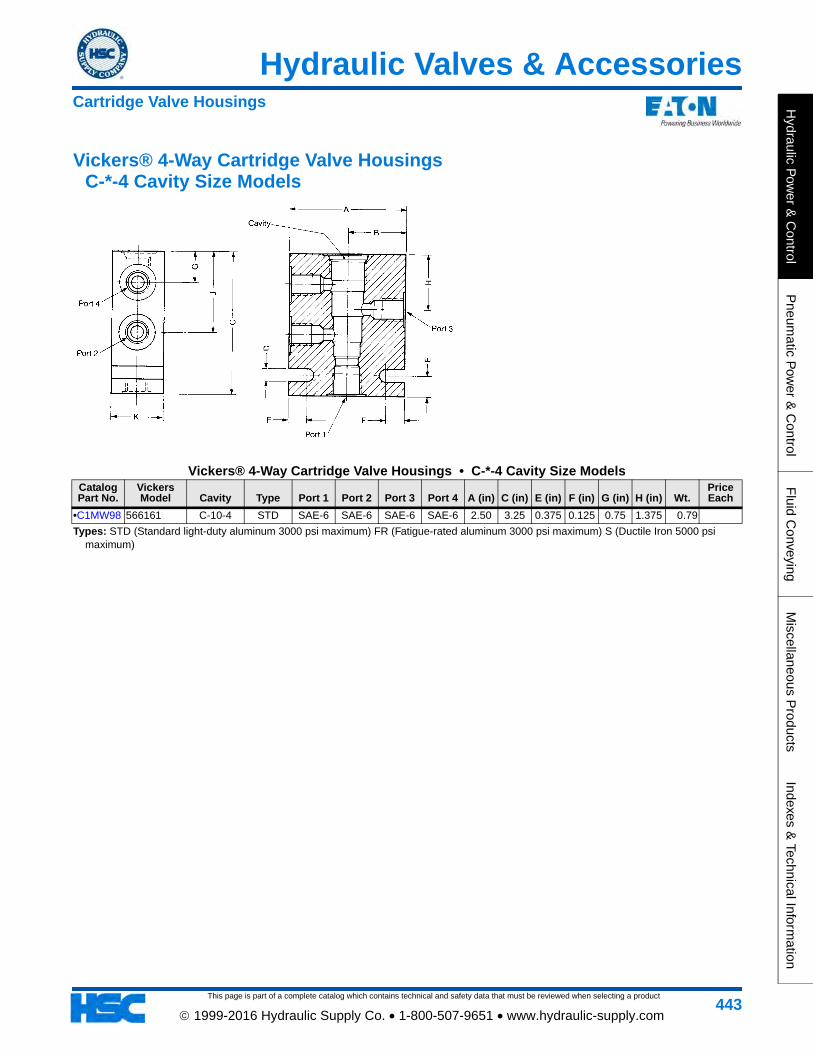
This page is part of a complete catalog which contains technical and safety data that must be reviewed when selecting a product
Hydraulic Valves & Accessories
Hydraulic P
ower &
Control
Pneum
atic Pow
er & C
ontrolF
luid Conveying
Miscellaneous P
roductsIndexes &
Technical Information
443 1999-2016 Hydraulic Supply Co. • 1-800-507-9651 • www.hydraulic-supply.com
Vickers® 4-Way Cartridge Valve Housings C-*-4 Cavity Size Models
Vickers® 4-Way Cartridge Valve Housings • C-*-4 Cavity Size ModelsCatalog Part No.
Vickers Model Cavity Type Port 1 Port 2 Port 3 Port 4 A (in) C (in) E (in) F (in) G (in) H (in) Wt.
Price Each
•C1MW98 566161 C-10-4 STD SAE-6 SAE-6 SAE-6 SAE-6 2.50 3.25 0.375 0.125 0.75 1.375 0.79
Types: STD (Standard light-duty aluminum 3000 psi maximum) FR (Fatigue-rated aluminum 3000 psi maximum) S (Ductile Iron 5000 psi maximum)
Cartridge Valve Housings

This page is part of a complete catalog which contains technical and safety data that must be reviewed when selecting a product
Hydraulic Valves & Accessories
Hyd
raul
ic P
ower
& C
ontr
olP
neum
atic
Pow
er &
Con
trol
Flu
id C
onve
ying
Mis
cella
neou
s P
rodu
cts
Inde
xes
& T
echn
ical
Info
rmat
ion
444 1999-2016 Hydraulic Supply Co. • 1-800-507-9651 • www.hydraulic-supply.com
Vickers® 3-Way Dual Cartridge Valve Housings 3 Port Cavity Models
Vickers® 3-Way Dual Cartridge Valve Housings • 3 Port Cavity ModelsCatalog Part No. Vickers Model Cavity Type Ports A (in) B (in) C (in) D (in) E (in) F (in) G (in) H (in) Wt.
Price Each
C1MG54 410AA00017A (C10807) A12336 STD SAE-8 3.00 5.00 1.50 0.43 1.42 1.59 3.41 5.47
C1MH17 C11561 A12336 FR SAE-8 3.00 5.00 1.50 0.43 1.42 1.59 3.41 5.47
A20081 STD SAE-16 3.00 5.00 1.50 0.43 1.42 1.59 3.41 5.47
C1MG93 B30237 A6610 STD SAE-8 2.50 4.00 1.25 0.35 1.04 1.25 2.75 4.37
•C1JZ95 410AA00015A (B10805) A6610 STD SAE-6 2.50 4.00 1.25 0.35 1.04 1.25 2.75 4.37 0.90
C1MH18 C11564 A6935 FR SAE-20 4.00 5.00 3.82 0.43 1.93 1.26 3.74 6.08
•C1AD18 02-160830 C-10-3S STD SAE-8 3.47 3.97 1.97 0.34 2.00 1.25 2.68 5.90 0.50
Types: STD (Standard light-duty aluminum 3000 psi maximum) FR (Fatigue-rated aluminum 3000 psi maximum) S (Ductile Iron 5000 psi maximum)
Note: Mounting hole style and location may vary from diagram.
Cartridge Valve Housings

This page is part of a complete catalog which contains technical and safety data that must be reviewed when selecting a product
Hydraulic Valves & Accessories
Hydraulic P
ower &
Control
Pneum
atic Pow
er & C
ontrolF
luid Conveying
Miscellaneous P
roductsIndexes &
Technical Information
445 1999-2016 Hydraulic Supply Co. • 1-800-507-9651 • www.hydraulic-supply.com
Vickers® Cartridge Valve Coils
Vickers® Cartridge Valve CoilsCatalog Part No. Vickers Part No. Vickers Model Series Voltage Connector Other Features Wt.
Price Each
C1JY62 300AA00121A MCSCH012DG000010 H Series 26 Watt 12VDC DIN 43650 0.60
C1JY63 300AA00122A MCSCH024DG000010 H Series 26 Watt 24VDC DIN 43650 0.50
•C1AD35 02-178104 SC024SPJ00 J Series 20 Watt 24VAC 1/2 NPT Conduit 1.00
•C1AD36 02-178106 SC120APJ00 J Series 20 Watt 120VAC 1/2 NPT Conduit Full Bridge Rectifier 1.00
•C1JY60 300AA00085A MCSCJ115AG000010 J Series 20 Watt 120VAC DIN 43650 Full Bridge Rectifier 0.50
C1JY61 300AA00086A MCSCJ230AG000010 J Series 20 Watt 230VAC DIN 43650 Full Bridge Rectifier 0.51
C1AD37 02-178109 SC240APJ00 J Series 20 Watt 240VAC 1/2 NPT Conduit Full Bridge Rectifier 0.75
•C1AD31 02-178078 SC012DPJ00 J Series 20 Watt 12VDC 1/2 NPT Conduit 1.00
•C1JY58 300AA00081A MCSCJ012DG000010 J Series 20 Watt 12VDC DIN 43650 0.61
•C1KJ80 300AA00095A MCSCJ012DW0B0010 J Series 20 Watt 12VDC Flying Lead 0.60
•C1AD32 02-178079 SC024DPJ00 J Series 20 Watt 24VDC 1/2 NPT Conduit 2.00
•C1JY59 300AA00082A MCSCJ024DG000010 J Series 20 Watt 24VDC DIN 43650 0.50
•C1KJ81 300AA00096A MCSCJ024DW0B0010 J Series 20 Watt 24VDC Flying Lead
C1LX16 300AA00045A MCSCP115AG000010 P Series 23 Watt 115VAC DIN 43650
C1LX17 300AA00046A MCSCP230AG000010 P Series 23 Watt 230VAC DIN 43650
C1KJ79 300AA00042A MCSCP024DG000010 P Series 23 Watt 24VDC DIN 43650 0.34
C1KU72 300AA00005A MCSCS115AG000010 S Series 20 Watt 115VAC DIN 43650 0.30
C1MY96 300AA00001A MCSCS012DG000010 S Series 20 Watt 12VDC DIN 43650
•C1KJ78 300AA00009A MCSCS012DQ000010 S Series 20 Watt 12VDC 1/4" Spade 0.30
C1JL52 02-160691 SC024DGS00 S Series 16 Watt 24VDC DIN 43650 0.34
Protection of Internally Rectified AC Coils: The rectifiers used in AC coils may require protection from high voltage surges in some electrical circuits containing highly inductive or capacitive components. These include certain types of motors, solenoids, relays and transformers. Protection is simple and inexpensive. It consists of installing a commercially available voltage surge suppressor like the GE MOV Varistor V130LA20A for 115VAC or the V250LA20A for 230VAC across the AC line supplying the rectified components. A single suppressor will normally protect all of the rectified components in the circuit. (See circuit diagram above. No inductive or capacitive loads can be installed between the surge suppressor and rectified valves).
Accessories for CoilsCatalog Part No. Part Number Description Wt.
Price Each
C1BT31 565560 Blank Nameplate, Circular, Fits between Coil and Nut 0.01
Cartridge Valve Coils
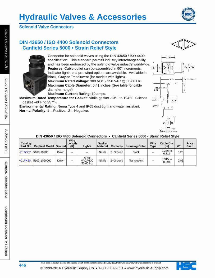
This page is part of a complete catalog which contains technical and safety data that must be reviewed when selecting a product
Hydraulic Valves & Accessories
Hyd
raul
ic P
ower
& C
ontr
olP
neum
atic
Pow
er &
Con
trol
Flu
id C
onve
ying
Mis
cella
neou
s P
rodu
cts
Inde
xes
& T
echn
ical
Info
rmat
ion
446 1999-2016 Hydraulic Supply Co. • 1-800-507-9651 • www.hydraulic-supply.com
DIN 43650 / ISO 4400 Solenoid Connectors Canfield Series 5000 • Strain Relief Style
Connector for solenoid valves using the DIN 43650 / ISO 4400 specification. This standard permits industry interchangeability and has been embraced by the solenoid valve industry worldwide. Features: Cable outlet can be assembled in 90° increments. Indicator lights and pre-wired options are available. Available in Black, Gray or Translucent (for models with lights). Maximum Rated Voltage: 300 VDC / 250 VAC @ 50/60 Hz. Maximum Cable Diameter: 0.41 inches (See table for cable diameter range). Maximum Current Rating: 10 amps.
Maximum Rated Temperature for Gasket: Nitrile gasket -13°F to 194°F. Silicone gasket -40°F to 257°F.
Environmental Rating: Nema Type 4 and IP65 dust tight and water resistant. Normal Polarity: 1 = Positive. 2 = Negative.
DIN 43650 / ISO 4400 Solenoid Connectors • Canfield Series 5000 • Strain Relief Style
Catalog Part No. Canfield Model Ground
Wire Length
(ft) LightsGasket Material Contacts Housing Color
Wire Type
Cable Dia. (in) Wt.
Price Each
•C1BS52 5100-10900 Down -- -- Nitrile 2+Ground Black -- 0.236 to 0.315 0.25
•C1FK20 5103-1090000 Down --6-48
VAC/VDC 50/60 Hz
Nitrile 2+Ground Translucent -- 0.315 to 0.394 0.05
Solenoid Valve Connectors

Hydraulic Valves & Accessories
This page is part of a complete catalog which contains technical and safety data that must be reviewed when selecting a product
Hydraulic P
ower &
Control
Pneum
atic Pow
er & C
ontrolF
luid Conveying
Miscellaneous P
roductsIndexes &
Technical Information
447 1999-2016 Hydraulic Supply Co. • 1-800-507-9651 • www.hydraulic-supply.com
All-Molded DIN Solenoid Connectors Canfield Series 5J
The Canfield Series 5J all-molded DIN solenoid valve connector/gasket/cord assembly offers a completely molded design that is far better for environmental integrity than field wire versions. Made from rugged yet flexible polyurethane, the connector housing boasts high durability factors
and application versatility. The low profile “90°” interface/cord configuration allows for installation in many limited space applications. The integrated gasket design boasts an IP67/NEMA 6 rating and makes it impossible to lose the gasket.
Maximum Rated Voltage: 250VAC 50/60 Hz, 300VDC. Maximum Rated Current: 10 amps (ISO and Mini), 6 amps (Sub Micro). Ambient Temperature Rating: -13°F to 176°F. Environmental Rating: IP67 and NEMA 6, dust tight and water resistant. Cable Conductor Colors: White black & green (US), brown blue & yellow/green (European). Conductor Wire Size: 18 gauge (ISO & Mini), 20 gauge (Sub Micro).
All-Molded DIN Solenoid Connectors • Canfield Series 5J
Catalog Part No. Canfield Model
Connector Type
Cord Length
(ft) ContactsOperating
VoltageSuppression
Type LightsWire
OptionHousing
Color Wt.Price Each
•C1HW97 5J664-000-US0A ISO DIN 43650 6 ft 2 + Dual
Ground -- None No US Black 0.32
Solenoid Valve Connectors

This page is part of a complete catalog which contains technical and safety data that must be reviewed when selecting a product
Hydraulic Valves & Accessories
Hyd
raul
ic P
ower
& C
ontr
olP
neum
atic
Pow
er &
Con
trol
Flu
id C
onve
ying
Mis
cella
neou
s P
rodu
cts
Inde
xes
& T
echn
ical
Info
rmat
ion
448 1999-2016 Hydraulic Supply Co. • 1-800-507-9651 • www.hydraulic-supply.com
MINI Solenoid Connectors Canfield Series 5000
The Canfield Connector field wireable MINI solenoid valve connector is a high quality interconnection device for use with solenoid valves and pressure switches. The connector features a PG9 strain relief, 3/8" or 1/2" conduit wire pass through, all with screw terminals for wire connections. The MINI accommodates wire from .240" to .410" diameter as a standard with an AWG of 14 maximum. Environment resistance of NEMA 4 / IP 65 along with versions which are CSA approved ensure long trouble free service. Current maximum of 10 Amps and the temperature rating of -40° to +125°C encompasses most applications. The interface is an industry standard.
Features: Cable outlet can be assembled in 180° increments. Indicator lights and pre-wired options are available. Available in Black, Gray or Translucent (for models with lights).
Maximum Rated Voltage: 300 VDC / 250 VAC @ 50/60 Hz. Maximum Cable Diameter: Strain Relief - 0.240 to 0.310 inches max. Conduit - 0.410
inches max. 14 AWG max conductor wire. Maximum Current Rating: 10 amps. Maximum Rated Temperature for Gasket: Nitrile gasket -13°F to 194°F. Silicone
gasket -40°F to 257°F. Environmental Rating: Nema Type 4 and IP65 dust tight and water resistant. Normal Polarity: 1 = Positive, High. 2 = Negative, Neutral
MINI Solenoid Connectors • Canfield Series 5000
Catalog Part No. Canfield Model Ground
Wire Length
(ft) LightsGasket Material Connector Type
Housing Color
Wire Type
Cable Dia. (in) Wt.
Price Each
C1LX39 5100-1010000 Down -- -- Nitrile PG9 Black --
•C1HZ99 5100-1030000 Down -- -- Nitrile 1/2 NPT Black -- 0.03
Solenoid Valve Connectors

Hydraulic Valves & Accessories
This page is part of a complete catalog which contains technical and safety data that must be reviewed when selecting a product
Hydraulic P
ower &
Control
Pneum
atic Pow
er & C
ontrolF
luid Conveying
Miscellaneous P
roductsIndexes &
Technical Information
449 1999-2016 Hydraulic Supply Co. • 1-800-507-9651 • www.hydraulic-supply.com
Power Plugs For Proportional Valves Vickers® EHH-AMP-702-D/E/J/K 10 Series
Description: Note: The newer 20 Series Power Plug is the current design and has additional features. Designed for use with non-feedback valves, these power plugs conform to the DIN 43650/ISO 4400 interface and include an integral amplifier and necessary adjustment potentiometers. This combination offers low cost solutions to many hydraulic control applications requiring proportional control. Features: Integral amplifier provides essential functions for control of proportional
valves. Fully short-circuit and reverse-polarity protected. Application: Primary applications are in the control of directly operated, non-feedback proportional valves where
the cost of more sophisticated electronic controls can be avoided. For Use With Valves: KDG4V-3(S)-H*-6*, KTG4V-3(S)-H*-6*, KDG4V-5-H*-3*, KTG4V-5-H*-3*. Note: Vickers publication GB-2115C provides the additional technical information necessary for proper application
of these power plugs. Contact us for technical assistance or to request a copy.
Power Plugs For Proportional Valves • Vickers® EHH-AMP-702-D/E/J/K 10 SeriesCatalog Part No.
Vickers Part No. Vickers Model Type Description Wt.
Price Each
C1EV31 02-326010 EHH AMP 702 D 10 D Controlled with 0-10 Volt command signal, 50ms to 600ms adjustable ramp time. 0.22
Electronic Control Components

This page is part of a complete catalog which contains technical and safety data that must be reviewed when selecting a product
Hydraulic Valves & Accessories
Hyd
raul
ic P
ower
& C
ontr
olP
neum
atic
Pow
er &
Con
trol
Flu
id C
onve
ying
Mis
cella
neou
s P
rodu
cts
Inde
xes
& T
echn
ical
Info
rmat
ion
450 1999-2016 Hydraulic Supply Co. • 1-800-507-9651 • www.hydraulic-supply.com
Side Ported Subplates • NFPA D03 - ISO 4401 Size 03
Side Ported Subplates • NFPA D03 - ISO 4401 Size 03Catalog Part No. Daman Model Material
Pressure Rating (psi) Port Location Port Threads A B Wt.
Price Each
C1CG87 A-D03-SP-S-6P Aluminum 3000 Side 3/8 NPT 1.00 2.50 0.23
C1CG88 A-D03-SP-S-6S Aluminum 3000 Side SAE-6 1.00 2.50 0.23
Subplate Mounting Hardware Included: (2) 1/4-20 x 7/8 Socket Head Cap Screws
Dual Ported Subplates • NFPA D03 - ISO 4401 Size 03
Dual Ported Subplates • NFPA D03 - ISO 4401 Size 03Catalog Part No. Daman Model Material
Pressure Rating (psi) Port Location Port Threads A B C Wt.
Price Each
•C1JF14 AD03SPSB6S Aluminum 3000 Side P-T-A-B, Bottom P-T SAE-6 1.50 2.50 3.44 1.12
C1EK42 AD03SPSB8S Aluminum 3000 Side P-T-A-B, Bottom P-T SAE-8 2.00 2.75 3.75 1.80
Subplate Mounting Hardware Included: (2) 1/4-20 x 1-1/2 Socket Head Cap Screws. (2) SAE-6 Hex Socket Plugs.
Subplates, Manifolds & Accessories

This page is part of a complete catalog which contains technical and safety data that must be reviewed when selecting a product
Hydraulic Valves & Accessories
Hydraulic P
ower &
Control
Pneum
atic Pow
er & C
ontrolF
luid Conveying
Miscellaneous P
roductsIndexes &
Technical Information
451 1999-2016 Hydraulic Supply Co. • 1-800-507-9651 • www.hydraulic-supply.com
Bottom Ported Subplates • NFPA D03 - ISO 4401 Size 03
Bottom Ported Subplates • NFPA D03 - ISO 4401 Size 03
Catalog Part No.
Vickers Part No. Vickers Model Material
Pressure Rating (psi)
Port Location Port Threads Wt.
Price Each
C1BQ64 466731 DGVM-3-10S Cast Iron 3600 Bottom SAE-8 3.03
Parallel Circuit Manifolds • NFPA D03 - ISO 4401 Size 03
Parallel Circuit Manifolds • NFPA D03 - ISO 4401 Size 03
Catalog Part No. Daman Model Material
Pressure Rating (psi)
Number of
StationsValve
SpacingGauge Port Port Threads and Options A Wt.
Price Each
C1NA53 A-D03-P-01-2-S/C Aluminum 3000 1 2.13 Yes
-10 SAE P & T, -8 SAE A & B, -6 SAE Gauge Port,
Includes Cavity for C-10-2 Relief Cartridge
•C1CG84 A-D03-P-02-2-P Aluminum 3000 2 2.13 Yes 1/2 NPT P & T, 3/8 NPT A & B, 1/4 NPT Gauge Port 4.25 3.95
Manifold Mounting Hardware Included: (8) 5/16-18 x 5/8 Hex Head Cap Screws and (2) Steel Brackets. Relief Cavity: P in nose
Subplates, Manifolds & Accessories

This page is part of a complete catalog which contains technical and safety data that must be reviewed when selecting a product
Hydraulic Valves & Accessories
Hyd
raul
ic P
ower
& C
ontr
olP
neum
atic
Pow
er &
Con
trol
Flu
id C
onve
ying
Mis
cella
neou
s P
rodu
cts
Inde
xes
& T
echn
ical
Info
rmat
ion
452 1999-2016 Hydraulic Supply Co. • 1-800-507-9651 • www.hydraulic-supply.com
Parallel Circuit Cover Plates • NFPA D03 - ISO 4401 Size 03
Parallel Circuit Cover Plates • NFPA D03 - ISO 4401 Size 03Catalog Part No. Daman Model Material Pressure Rating (psi) Gauge Port (P) Wt.
Price Each
C1CG83 A-D03-CP-P Aluminum 3000 No 0.23
Cover Plate Mounting Hardware Included: (4) 10-24 x 1 Socket Head Cap Screws, (4) -012 Viton® 75 durometer O-Rings and (1) 0.12 dia x 0.25 long Locating Pin.
Dual Ported Subplates • NFPA D05 - ISO 4401 Size 05
Dual Ported Subplates • NFPA D05 - ISO 4401 Size 05
Catalog Part No. Daman Model Material
Pressure Rating (psi) Port Location Port Threads Wt.
Price Each
•C1CG90 A-D05-SP-SB-8S Aluminum 3000 Side P-T-A-B, Bottom P-T SAE-8 2.49
Subplate Mounting Hardware Included: (2) 3/8-16 x 1-1/2 Socket Head Cap Screws. (2) SAE-8 Hex Socket Plugs.
Subplates, Manifolds & Accessories