hydro 2007 paper peribonka dam - bauer dam · pdf filemodulus, permeability); in comparison,...
TRANSCRIPT

Peribonka dam in Canada A dam made possible by most modern
ground engineering techniques S.Balian, engineer W. G. Brunner, Hon. Prof., Dipl.-Ing. Martin Heinrich Divisional Director Marketing Director Head of Division BAUER Spezialtiefbau GmbH BAUER Maschinen GmbH BAUER Spezialtiefbau GmbH International Division [email protected] Int. Projects and Services [email protected] P. O. Box 1260 [email protected] P.O. Box 1260 86522 Schrobenhausen, Germany P. O. Box 1260 86522 Schrobenhausen, Germany 86522 Schrobenhausen, G Introduction The Peribonka dam, a 380 MW hydroelectric project, owned by Hydro-Quebec of Quebec, Canada, and designed by SNC Lavalin, is currently under construction, about 600 Km North East of Montreal. The project, for a total scheduled investment of 1.2 billion dollar, is due to be put into service in December 2007. The construction of an exceptionally deep cut-off wall under the main dam body, to create a waterproof barrier in highly permeable riverbed alluvia, was completed end of October 2006. The cut-off wall, made of plastic concrete, was exceptional by its depth, of almost 116m, and by the extremely complex geotechnical surrounding. Only a decade ago, the Peribonka dam would not have been deemed feasible due to the extreme complexity of the geotechnical works. The ground engineering works package was contracted by Hydro-Quebec to the international specialist contractor BAUER Spezialtiefbau GmbH of Germany in February 2005. BAUER commissioned a hydraulic cutter, the CBS CBC 135, biggest ever manufactured, with new features, designed specifically for the construction of the Peribonka dam cut-off wall. The preliminary geotechnical investigation boreholes had revealed that at the dam location the bedrock plunged to exceptional depths, forming a deep glacial gully. Beside the extreme depth of the bedrock, the design was further complicated by the presence of hard rock including granite, with strength sometimes in excess of 200 MPa, quasi vertical rock cliffs, rock overhangs, and gully's filling by some coarse alluvia, including boulders. Hydro-Quebec and SNC Lavalin designed a 1.50 m wide plastic concrete cut-off wall extending to the full depth of the glacial gully, with limited rock embedment of the wall, leaving open areas along the interface to the bedrock, combined with cement grouting in the areas left open. BAUER was awarded the contract on the basis of an alternative design: the plastic concrete cut-off wall was designed by Bauer to be completely embedded in the bedrock, a design which avoided any potentially hazardous area to be sealed by cement grouting.
Figure 1: General layout of the hydro-electrical project
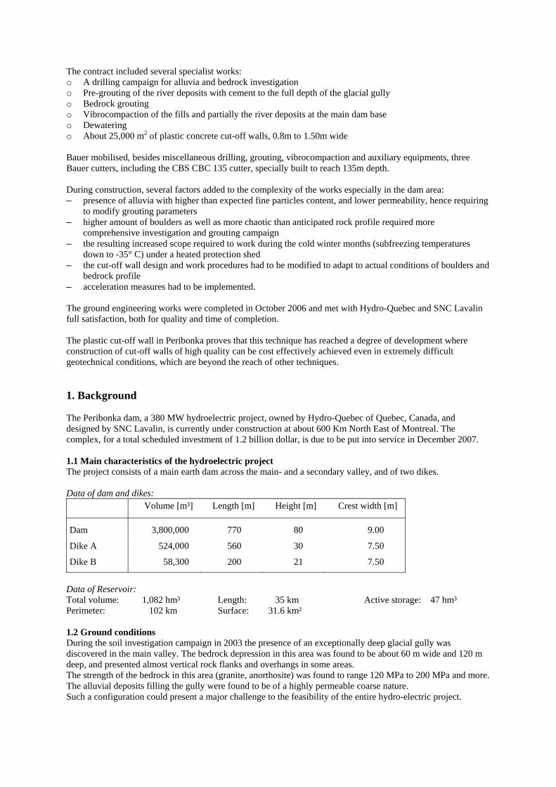
The contract included several specialist works: o A drilling campaign for alluvia and bedrock investigation o Pre-grouting of the river deposits with cement to the full depth of the glacial gully o Bedrock grouting o Vibrocompaction of the fills and partially the river deposits at the main dam base o Dewatering o About 25,000 m2 of plastic concrete cut-off walls, 0.8m to 1.50m wide Bauer mobilised, besides miscellaneous drilling, grouting, vibrocompaction and auxiliary equipments, three Bauer cutters, including the CBS CBC 135 cutter, specially built to reach 135m depth. During construction, several factors added to the complexity of the works especially in the dam area: – presence of alluvia with higher than expected fine particles content, and lower permeability, hence requiring
to modify grouting parameters – higher amount of boulders as well as more chaotic than anticipated rock profile required more
comprehensive investigation and grouting campaign – the resulting increased scope required to work during the cold winter months (subfreezing temperatures
down to -35° C) under a heated protection shed – the cut-off wall design and work procedures had to be modified to adapt to actual conditions of boulders and
bedrock profile – acceleration measures had to be implemented. The ground engineering works were completed in October 2006 and met with Hydro-Quebec and SNC Lavalin full satisfaction, both for quality and time of completion. The plastic cut-off wall in Peribonka proves that this technique has reached a degree of development where construction of cut-off walls of high quality can be cost effectively achieved even in extremely difficult geotechnical conditions, which are beyond the reach of other techniques. 1. Background The Peribonka dam, a 380 MW hydroelectric project, owned by Hydro-Quebec of Quebec, Canada, and designed by SNC Lavalin, is currently under construction at about 600 Km North East of Montreal. The complex, for a total scheduled investment of 1.2 billion dollar, is due to be put into service in December 2007. 1.1 Main characteristics of the hydroelectric project The project consists of a main earth dam across the main- and a secondary valley, and of two dikes. Data of dam and dikes:
Volume [m³] Length [m] Height [m] Crest width [m]
Dam 3,800,000 770 80 9.00
Dike A 524,000 560 30 7.50
Dike B 58,300 200 21 7.50
Data of Reservoir: Total volume: 1,082 hm³ Length: 35 km Active storage: 47 hm³ Perimeter: 102 km Surface: 31.6 km² 1.2 Ground conditions During the soil investigation campaign in 2003 the presence of an exceptionally deep glacial gully was discovered in the main valley. The bedrock depression in this area was found to be about 60 m wide and 120 m deep, and presented almost vertical rock flanks and overhangs in some areas. The strength of the bedrock in this area (granite, anorthosite) was found to range 120 MPa to 200 MPa and more. The alluvial deposits filling the gully were found to be of a highly permeable coarse nature. Such a configuration could present a major challenge to the feasibility of the entire hydro-electric project.

Picture 1: Arial view of the dam-/dike area
2. Cut-off wall and alternatives at Peribonka 2.1 Grout curtain vs. plastic concrete wall In recent years cement-bentonite cut-off walls and more recently plastic concrete cut-off walls have been used effectively in dam constructions, instead of cement grouted curtains. The advantages of the cut-off wall compared to more traditional cement grout curtains are numerous: o Quality: substitution of the soil by material (plastic concrete) of controlled characteristics (resistance, E
modulus, permeability); in comparison, in alluvial soils a grout curtain is made of cement grout mixed with soils in situ, where the grout circulation is only partially controlled, resulting in soil-cement mixes of widely variable dosages
o In addition to the wall's overall integrity, safe and well defined rock key at its base and its flanks o Time of project completion: even in the presence of unforeseen soil conditions, with modern soil cutting
techniques the progress of cut-off walls is better controlled than with grouting techniques, where the result is a function of actual grout absorption in given soils
o Cost: the experience shows that in most cases cut-off walls are overall economically competitive against grout curtains
The most crucial advantage is that cut-off walls can be installed in situations where grouted curtains would not be feasible with a reasonable guarantee of the result. 2.2 Cut-off wall construction principle The general construction principle of a cut-off wall, similar to that of reinforced concrete diaphragm walls, is commonly known, and outlined here in its general principle only. Cut-off walls are constructed by joining vertical panels, each panel being excavated individually. The individual panel excavation is done under bentonite slurry to ensure excavation stability, and thereafter concrete is poured by tremie method. The standard sequence of construction is by primary panels consisting of two primary bites and one secondary bite in between. Secondary single bite panels overcut the two adjacent concreted primary panels at both its edges. This results in cold joints with low permeability at both extremities of the secondary panel.

Because the wall is built by individual panels, it is crucial to prevent deviations of panels from their theoretical positions during excavation. Deviations out of control would result in open gaps in the wall joints, and hence jeopardise the integrity of the wall. Beside technological boundaries, the degree of accuracy limits the depth to which cut-off walls can be constructed. Traditionally cut-off and diaphragm walls were and are still excavated with clamshells. However since the seventies new generations of excavation equipment based on milling techniques, trench cutters have been developed. The trench cutter continuously removes soil or rock from the bottom of the trench, breaks it up and mixes it with the bentonite slurry in the trench. The slurry charged with soil particles is pumped through a ring main of hose pipes to the desanding plant where it is cleaned and returned to the trench. The cutters have several advantages compared to clamshells: higher performance, more accuracy with on board inclinometers, continuous position steering systems, real time monitoring of the cutter position in the excavated trench, hence possibility to excavate deeper, automatic steering, and higher capacity to cut hard materials. 2.3 The BAUER Cutter The heart of the system, the actual BAUER trench cutter consists of a heavy steel frame with two drive gears attached to its bottom end which rotate in opposite direction round horizontal axes. Cutter wheels, suitable in this case for the soil and rock to be worked in, are mounted onto the drive gears. As they rotate, the soil beneath the cutter is continuously removed, broken up, mixed with the bentonite slurry in the trench and removed towards the opening of the suction box. The BC 40/50 trench cutter breaks up the soil and rock into max. 80 mm fractions. The openings of the suction box are reduced to half the diameter of the hose pipe in order to prevent blockages in the mud hose pipes. The lay out of round shank chisels on a rock cutter wheel ensures that the entire rectangular cross section of the cut-off wall is cut by the cutter. The ridge remaining in the area of the gear shield is effectively broken up by flapping teeth. In order to apply adequate crowd pressure on the cutting teeth or round shank chisels, the cutter frame can be surcharged with additional weights. Positioned immediately above the cutter wheels is the centrifugal pump which pumps the bentonite slurry charges with spoil or cuttings continuously to the surface and from there to the desanding-/regeneration plant. Built into the cutter is an electronic inclinometer which measures the cutter's vertical deviation in two directions. The deviation is continuously displayed both in degrees and in centimetres on the CCS monitor inside the operator's cab, which later also can be used for QA/QC purposes. If the cutter deviates from its vertical axis, its position can be adjusted with the help of the hydraulically operated steering plates.
Picture 2: GCS monitor in operators cab Picture 3: Steering plate system 2.4 Plastic concrete cut-off wall at the glacial gully of Peribonka The soil conditions at the glacial gully presented several difficulties, which combined together exclude the cement grout curtain option: – The depth of the bedrock in the central area was expected to reach 120 m – The bedrock, of variable quality, presents a complex profile with slope variations in all directions, sub-
vertical to vertical faces, overhangs, and locally unpredictable position – Presence of small size to large (more than 8 m) boulders – The alluvia consist of generally coarse materials, with higher fines content in some areas, and areas of
coarse sediments with very little fine content, which results in permeability ranging from few cm/s to the order of 10-6 m/s.

Adding the rock strength, in the range of 120 to more than 200 N/mm², the above conditions form a configuration where plastic concrete cut-off walls have not been installed in the past.
Figure 2: Dam profile
Hydro-Quebec and SNC Lavalin came up with a plastic concrete cut-off wall solution combined with local grout curtains. The solution consisted of limiting the embedment of the wall in the rock to one third length of each panel, creating open areas along the interface between the wall and bedrock. These areas were supposed to be later closed by pressure grouting with "tube-à-manchettes".
Figure 3: Cut-off wall combined with cement grouting vs. wall completely embedded in bedrock Prior to constructing the cut-off wall, the alluvia in the glacial gully were to be pre-grouted, to mitigate the high permeability and the ensuing reduced stability during the wall excavation, due to possible large losses of bentonite slurry into the ground. In addition such general pre-grouting would result in added safety along the wall base, in the areas left open by the wall and grouted subsequently. Furthermore the pre-grouting campaign would target to cement the boulders which could be in the vicinity of the wall, thus preventing that such boulders or pieces of boulders fall into the trench during excavation. Also prior to the wall construction, an extensive drilling campaign would help better identifying the rock profile, and then grout the rock to reduce its permeability. 2.5 Extensive ground engineering work package The owner decided to contract all foundation works in a single separate package, through a selective international tender. The works tendered were: o Earthworks ca. 250,000m³ o Vibrocompaction of Dam Base ca. 85,000m² o Installation / Operation of Dewatering System

o Drilling & Grouting: Drilling ca. 13,000 lin m; Grouting ca. 5,500 to cement o Plastic Concrete Cut-Off-Walls: ca. 25,000m², widths 800 mm, 1200 mm and 1500 mm The cut-off walls are in the main valley, in particular the glacial gully and the secondary valley (ref. to Fig. 2), and the Dike A. The drilling and grouting package included grouting of the cut-off wall bases, pre-grouting of alluvia, and rock grouting. We will emphasize in the following on the most critical item, the cut-off wall in the glacial gully.
Figure 4: Overview of specialist foundation works 3. BAUER's alternative BAUER was of the opinion that the open areas along the cut-off wall in contact with the bedrock, although in relatively limited areas, could jeopardise the project precisely for the reasons which would make the effectiveness of a grout curtain uncertain in the given configuration. In the opinion of BAUER the cutter technology, with additional features, combined with a wall design adapted to the circumstances could overcome the extreme difficulties of the project. An alternative solution was proposed: The plastic concrete cut-off wall could be embedded completely in the bedrock, minimum 50 cm. Thus the pre-grouting scope would be reduced to its main purpose, i.e. improving the alluvia and boulders stability during the wall excavation. Together with BAUER's sister company BAUER Maschinen GmbH which is specialised in equipment manufacturing, a new cutter was developed specifically for Peribonka: – BC 50 cutter (torque 120 kNm each cutter wheel) – CBS CBC base carrier, depth capacity 135 m. – Special features were added: on board gyroscopes, improved efficiency steering flaps, protection against
falling rocks. BAUER developed a design of mixed strength cut-off wall panels, with higher strength at the lower levels, providing guidance to the cutter against rock in areas of quasi vertical bedrock. In addition, for the case of possible increases in excavation difficulties, due to the distinct possibility of more massive than expected boulder presence, as well as possible surprises at the bedrock profile, more conservative fall back measures were considered in the panel's geometry, the joints, and the construction sequencing.
4. Construction of the plastic cut-off wall Before the start of the wall's construction, the extensive drilling campaign confirmed concerns about: – massive presence of boulders – chaotic bedrock profile – higher than expected fine particles content in some areas, which could prevent the cement grout from
reaching targeted coarse areas The drilling and grouting campaign was adapted to the new findings and drilling quantities were substantially increased. Grouting procedures were modified to cope with high fines content. Here a drastic acceleration measure was taken by deciding with the owner to continue this campaign in the winter months, where no work was originally planned, due to subfreezing temperatures below -35° C. This was made possible by installing a winter protection heated shed. The plastic concrete cut-off wall design was adapted to the given circumstances by application of some of the fall back measures: transversal panels were introduced in areas of steep rock faces or secondary rock slopes, the length of overcut joints was increased according to local conditions, single bite panels were used more intensively. Three cutters were mobilised for this part of the works, one of which was kept in reserve.
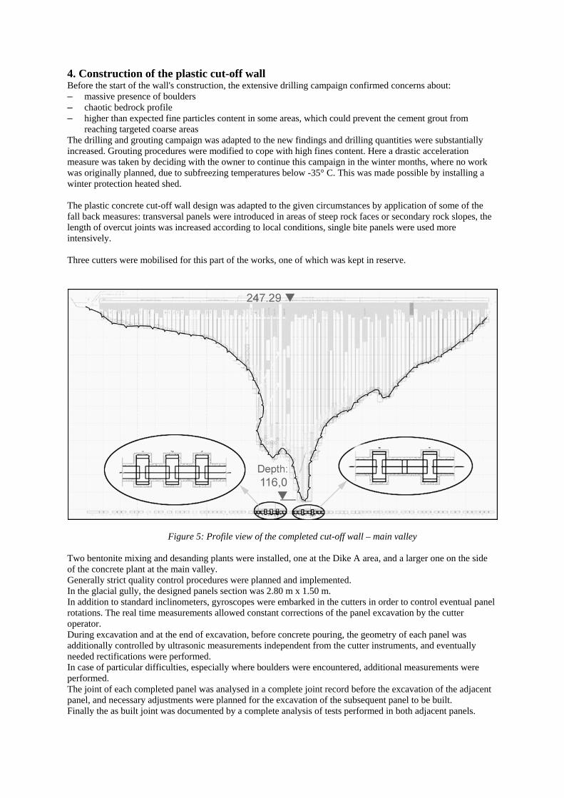
Figure 5: Profile view of the completed cut-off wall – main valley Two bentonite mixing and desanding plants were installed, one at the Dike A area, and a larger one on the side of the concrete plant at the main valley. Generally strict quality control procedures were planned and implemented. In the glacial gully, the designed panels section was 2.80 m x 1.50 m. In addition to standard inclinometers, gyroscopes were embarked in the cutters in order to control eventual panel rotations. The real time measurements allowed constant corrections of the panel excavation by the cutter operator. During excavation and at the end of excavation, before concrete pouring, the geometry of each panel was additionally controlled by ultrasonic measurements independent from the cutter instruments, and eventually needed rectifications were performed. In case of particular difficulties, especially where boulders were encountered, additional measurements were performed. The joint of each completed panel was analysed in a complete joint record before the excavation of the adjacent panel, and necessary adjustments were planned for the excavation of the subsequent panel to be built. Finally the as built joint was documented by a complete analysis of tests performed in both adjacent panels.

Performed plastic concrete cut-off walls: Cut-off wall Area Width Length Av. depth Max depthMain Dam 12,000 m² 1.50 m to 0.80 m 310 m 39 m 115.50 mDike A 15,800 m² 0.80 m 450 m 35 m 50 m
Picture 4: Two trench cutters and auxiliary equipment excavating at the main valley
The works were carried out at the dam and the Dike A locations from September to December 2005, and after interruption during the coldest months, from March to October 2007. All works were completed to the full satisfaction of Hydro-Quebec and SNC Lavalin. The dam will be put into service in December 2007. 5. Conclusion With the plastic cut-off wall constructed in Peribonka, this technique is proven to provide solutions for dams in ground conditions which are beyond the limits of other techniques such as cement grouted cut-offs. Furthermore the plastic concrete cut-off wall provides a high quality, cost effective and time saving solution for all types of dams constructed on permeable formations.

Picture 5: Cut-off wall works on the main dam
The Authors S. Balian, civil engineer from Ecole Centrale des Arts et Manufactures of Paris, has spent his whole career in special foundations and geotechnical works. He has worked for several international contractors, and has been in charge of several large projects. He has worked the last nine years for Bauer Spezialtiefbau GmbH, and is currently one of the international directors at the head office of the company, in charge of several subsidiaries. W.G. Brunner graduated as Dipl.-Ing. in Civil Engineering from the Technical University Stuttgart, Germany in 1968 and worked for 2 German construction companies before joining BAUER Spezialtiefbau GmbH, Schrobenhausen, Germany in 1972. He started as Project Engineer, became Managing Director of BAUER's sister companies, Director of overseas activities and today Marketing Director of BAUER Maschinen GmbH. He got an Honorary Professor award from the University of Applied Sciencies Lausitz, Germany. M. Heinrich graduated as Dipl.-Ing. in Civil Engineering from the Technical University Munich, Germany in 1990 to join BAUER Spezialtiefbau GmbH, Schrobenhausen, Germany the same year. Starting as Design Engineer and later Project Manager overseas, he was involved in some of BAUER's sophisticated dam cut-off wall projects. During the last years, he developed and managed the actual International Projects and Service Department.