hydro power
DESCRIPTION
hydro power pptTRANSCRIPT
Development of very small house hold hydraulic power generation unit
• Project Location : Deptt. of EOES, CAET, Dapoli.
• Name of the scientist :
Mrs. S. V. Aware, Assistant Professor (Physics and Electronics)
• Name of Co-scientist: Dr. Khandetod Y.P. Prof. and Head, Dept. of EOESDr. Aware V.V. Associate Prof. , Dept. of FMPDr. Mohod A.G., Associate Prof. , Dept. of EOESEr. R.M.Dharaskar, Assistant Professor, Dept of EOESEr. H. Y. Shrirame ,S.R.A., Dept of EOES

Objectives of experiment
1.To develop/procure very small house hold hydraulic power generation unit.
2. To test its performance.

Need of Hydropower generation unit-
•Konkan is a coastal part of Maharashtra between western ghat and Arabian Konkan is a coastal part of Maharashtra between western ghat and Arabian Sea. It receives heavy rainfall about 3000-4500 mm in June to October. Due to Sea. It receives heavy rainfall about 3000-4500 mm in June to October. Due to the heavy rain, it is observed that there is frequent power cut due to problems the heavy rain, it is observed that there is frequent power cut due to problems in transmission lines. This situation is very common during rainy season in rural in transmission lines. This situation is very common during rainy season in rural areas sometimes observed in urban areas too. areas sometimes observed in urban areas too. •Rain water falling on roof tops is taken through pipes to the ground and is Rain water falling on roof tops is taken through pipes to the ground and is charged to nalas. The gushing water from the roof top possesses kinetic energy charged to nalas. The gushing water from the roof top possesses kinetic energy due to velocity which could be used to run turbine to generate electric power.due to velocity which could be used to run turbine to generate electric power.• In In konkankonkan about all concrete houses are two storied , having ground floor about all concrete houses are two storied , having ground floor with slab and the first floor tine roofed to avoid any leakage of water. The with slab and the first floor tine roofed to avoid any leakage of water. The average height of ground plus one house is about 8 to 9 meters. Doing simple average height of ground plus one house is about 8 to 9 meters. Doing simple calculations, it is observed that from a house having roof top of 10 m x 10 m, calculations, it is observed that from a house having roof top of 10 m x 10 m, about 50 to 60 watt electric power could be generated. about 50 to 60 watt electric power could be generated. •Using this electric power four to five LED lamps of 10 watt capacity could be Using this electric power four to five LED lamps of 10 watt capacity could be powered. This could be very effective if coupled with solar powered electricity powered. This could be very effective if coupled with solar powered electricity generation. generation.

Water flow from roof
Collection of water in tank
DC GENERATOR
Voltage regulator
Charging Unit
Flowchart of hydropower generated electricity
Turbine

Classification of small hydropower
Class Station capacityClass Station capacity
Pico Less than 5kw
Micro 5 kW to 100 kW
Mini 101 kW to 2000 kW
Small 2001 kW to 25000 kW

Flow rate, head and power relationship for PELTON WHEEL
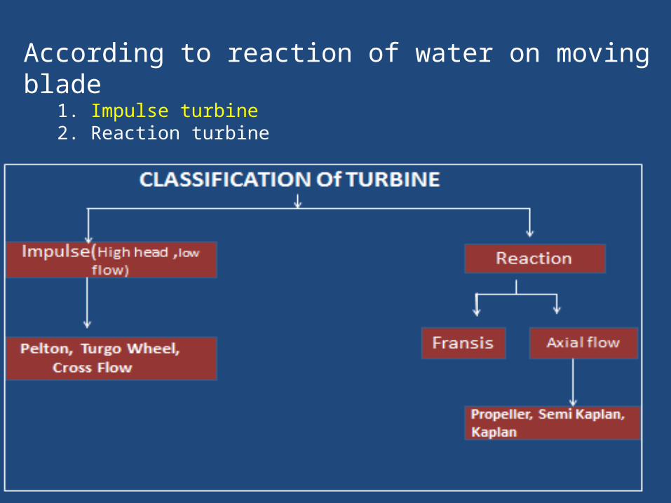
According to reaction of water on moving blade 1. Impulse turbine2. Reaction turbine
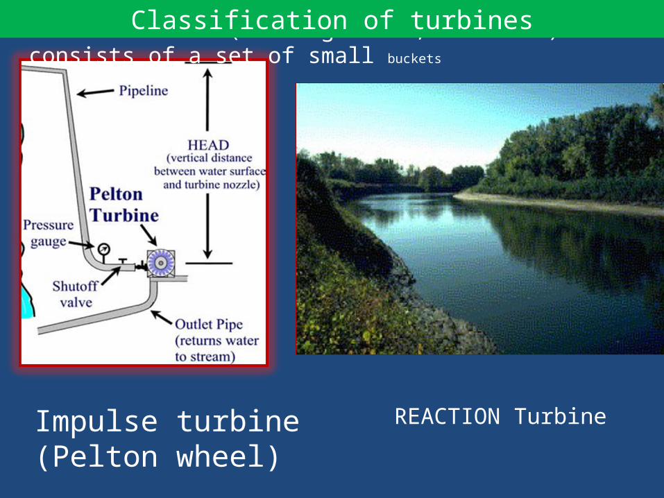
Impulse turbine (Pelton wheel)
REACTION Turbine
Pelton turbine (for high head, low flow) consists of a set of small bucketsClassification of turbines

Impulse turbine (Pelton Wheel) : Impulse turbines, which have the least complex design, are most commonly used for
high-head microhydro systems. They rely on the velocity of water to move the turbine wheel, which is called the runner. The most common types of impulse turbines include the Pelton wheel .
The Pelton wheel uses the concept of jet force to create energy. Water is funneled into a pressurized pipeline with a narrow nozzle at one end. The water sprays out of the nozzle in a jet, striking the cupped buckets attached to the wheel. The impact of the jet spray on the curved buckets creates a force that rotates the wheel .

Design of hydraulic turbine : . Let annual rainfall = 3500 mm . Daily rainfall = 70 mm considering 50 days of rainfall. . Discharge of water expected from roof size 10 m x 10 m for 2 hours
= (1000 x 1000 x 7/1000)/2 x 60 x60 = 0.97 lps ≈1 lps
Output power in watt = Q (lps) x H (m) x ŋ x 9.81 = 1lps x 9.1m x 0.6 x 9.81 = 53.56 watt
cal

(Reference- M.N. Prakash, 2007)

Design Parameters :
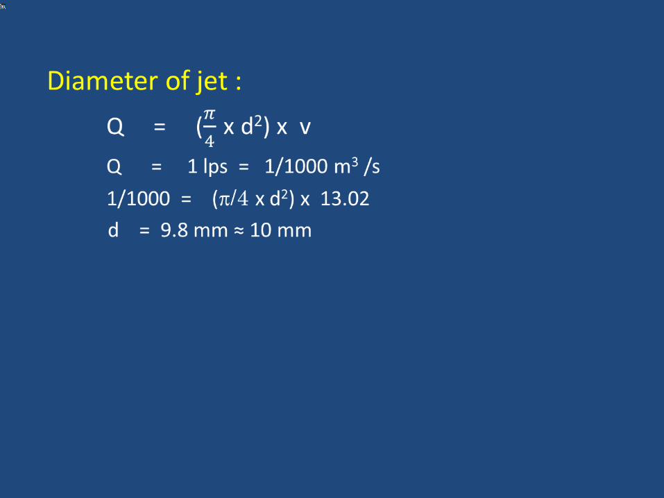
•Diameter of vane(D) = 42cm•Diameter of jet (d) = 1 cm = 10mm•Jet ratio (m) = D/d
= 42/1 = 42•Number of bucket = 0.5 m + 15
= 36•Bucket width = 5 x d
= 5 x 1 = 5.0 cm• Bucket depth = 1.2 x d = 1.2 cm
cal
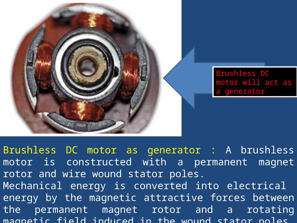
Brushless DC motor as generator : A brushless motor is constructed with a permanent magnet rotor and wire wound stator poles.Mechanical energy is converted into electrical energy by the magnetic attractive forces between the permanent magnet rotor and a rotating magnetic field induced in the wound stator poles.
Brushless DC motor will act as a generatorBrushless DC motor will act as a generator
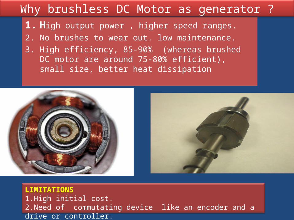
1. High output power , higher speed ranges.2. No brushes to wear out. low maintenance.3. High efficiency, 85-90% (whereas brushed DC motor are around
75-80% efficient), small size, better heat dissipation
Why brushless DC Motor as generator ?
LIMITATIONS1.High initial cost.2.Need of commutating device like an encoder and a drive or controller.
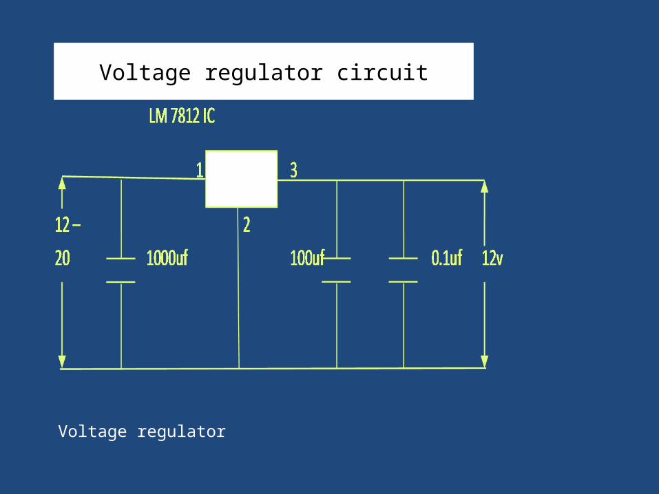
Voltage regulator circuit
Voltage regulator
Refrences
1. Design Considerations for Hydropower Development In aWater Distribution System by By David P. Chamberlain, Ed Stewart, Fei-Fan Yeh and Michael T. StiftSan Diego County Water Authority, San Diego, California, USA
2. Hydraulics and Hydraulic Machines by Dr. M.N. She sha Prakash, Professor, J.N.N. College of Engineering, Shimoga
3. Vinney Chokko, 2013 “Roof water harvesting for CAET building” Unpublished B.Tech. Thesis.

THANKS

• TURBINE : Pelton wheel material - Silicon Bronze/ Stainless Steel • Turbine Casing = Stainless Steel • Over head pipe diameter = 150 mm • Operating head = 5 to 150 m • Flow rate = 0.5 to 10 lps • Standard Nozzle material = Stainless Steel • Nozzle diameter range = 5 to 20 mm at 2 mm intervals
Specifications

GENERATOR •Generator output : 50 W to 1000 W •DC Generator : Permanent magnet brushless •Voltage : 12 VDC •Generator to turbine coupling :Geared
SYSTEM CONTROL •Voltage range :10 - 50 V •Power rating : 1000 Watt at 48 V SYSTEM MONITORING for charging current, voltage and hydraulic pressure
SYSTEM PROTECTION circuit


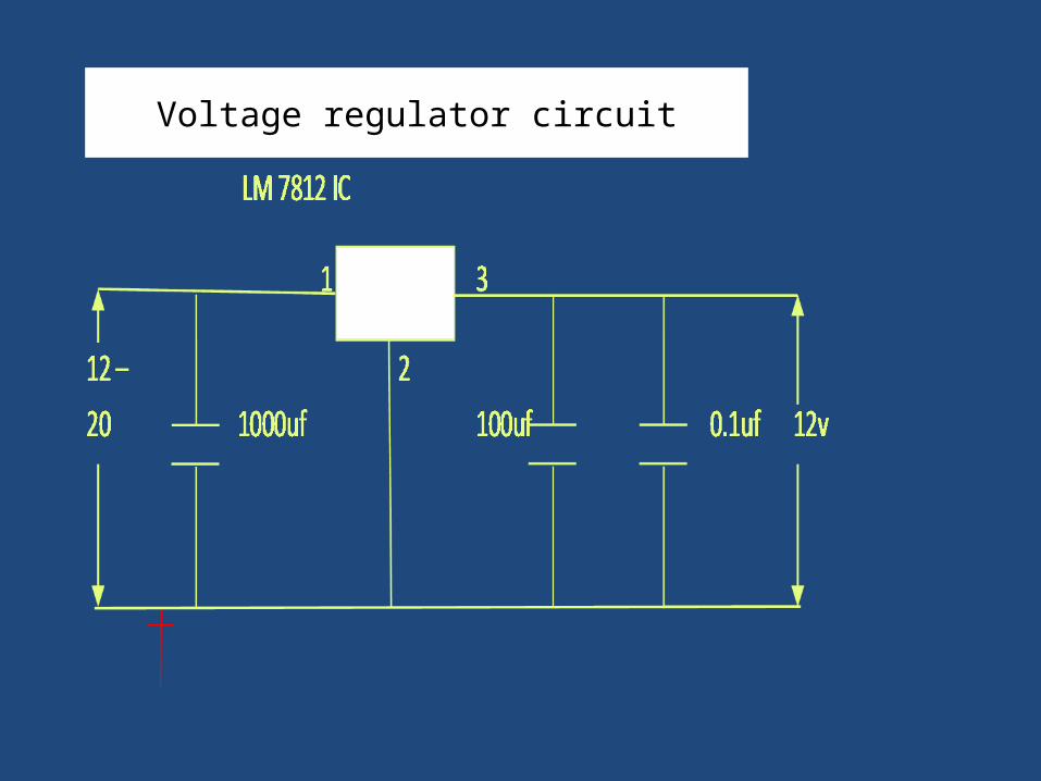
Voltage regulator circuit
Refrences
1. Design Considerations for Hydropower Development In aWater Distribution System by By David P. Chamberlain, Ed Stewart, Fei-Fan Yeh and Michael T. StiftSan Diego County Water Authority, San Diego, California, USA2.
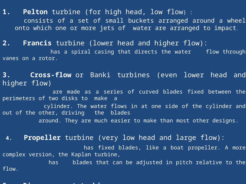
1. Pelton turbine (for high head, low flow) :
consists of a set of small buckets arranged around a wheel onto which one or more jets of water are arranged to impact.
2. Francis turbine (lower head and higher flow): has a spiral casing that directs the water flow through vanes on a rotor.
3. Cross-flow or Banki turbines (even lower head and higher flow) are made as a series of curved blades fixed between the perimeters of two disks to make a cylinder. The water flows in at one side of the cylinder and out of the other, driving the blades around. They are much easier to make than most other designs.
4. Propeller turbine (very low head and large flow): has fixed blades, like a boat propeller. A more complex version, the Kaplan turbine, has blades that can be adjusted in pitch relative to the flow.
5. River current turbine, which is like a wind-turbine immersed in water, can be used to extract power from with a large flow in a river, where there is virtually no head.

1. Pelton turbine (for high head, low flow) : consists of a set of small buckets arranged around a wheel onto which one or more jets of water are arranged to impact.
2. Cross-flow or Banki turbines (lower head and higher flow) are made as a series of curved blades fixed between the perimeters of two disks to make a cylinder. The water flows in at one side of the cylinder and out of the other, driving the blades around. They are much easier to make than most other designs.
3. Francis turbine (lower head and higher flow): has a spiral casing that directs the water flow through vanes on a rotor
4. Propeller turbine (very low head and large flow): has fixed blades, like a boat propeller. A more complex version, the Kaplan turbine, has blades that can be adjusted in pitch relative to the flow.