hydrodynamic issues in pams mandrel target fabrication · pdf filehydrodynamic issues in pams...
TRANSCRIPT
GA–A24438
HYDRODYNAMIC ISSUES IN PAMS MANDRELTARGET FABRICATION
byB.W. McQUILLAN, R. PAGUIO, P. SUBRAMANIAN,
M. TAKAGI, and A. ZEBIB
MARCH 2004
DISCLAIMER
This report was prepared as an account of work sponsored by an agency of the United StatesGovernment. Neither the United States Government nor any agency thereof, nor any of theiremployees, makes any warranty, express or implied, or assumes any legal liability orresponsibility for the accuracy, completeness, or usefulness of any information, apparatus,product, or process disclosed, or represents that its use would not infringe privately owned rights.Reference herein to any specific commercial product, process, or service by trade name,trademark, manufacturer, or otherwise, does not necessarily constitute or imply its endorsement,recommendation, or favoring by the United States Government or any agency thereof. The viewsand opinions of authors expressed herein do not necessarily state or reflect those of the UnitedStates Government or any agency thereof.
GA–A24438
HYDRODYNAMIC ISSUES IN PAMS MANDRELTARGET FABRICATION
byB.W. McQUILLAN, R. PAGUIO, P. SUBRAMANIAN,†
M. TAKAGI,‡ and A. ZEBIB†
†Mechanical & Areospace Engineering, Rutgers University‡Lawrence Livermore National Laboratory
This is a preprint of a paper presented at the 3rd InternationalConference on Inertial Fusion Sciences and Applications,Monterey, California, September 7–12, 2003 and to be publishedin Fusion Science and Technology.
Work supported bythe U.S. Department of Energy
under Contract Nos. DE-AC03-01SF22260,W-7405-ENG-48, and NSF Grant CTS-0211612
GENERAL ATOMICS PROJECT 30095MARCH 2004
GENERAL ATOMKICS REPORT GA-A24438 1
TUP01.38HYDRODYNAMIC ISSUES IN PAMS MANDREL TARGET FABRICATION
B.W. McQuillan,1 R. Paguio,1 P. Subramanian,2 M. Takagi,3 and A. Zebib2
1General Atomics, P.O. Box 85608, San Diego, California 92186-5608 USAemail: [email protected]
2Mechanical & Aerospace Engineering, Rutgers University, Piscataway, New Jersey 08854-8058 USA3Lawrence Livermore National Laboratory, P.O. Box 808, Livermore, California 94550 USA
Imperfections in PAMS mandrels critically govern thequality of final ICF targets. Imperfections in the mandrelscan have a wide range of origins. Here, we presentobservations of 3 types of imperfections, and data tosupport the proposal that hydrodynamic factors during thecuring of the mandrel are potential causes of theseimperfections.
I.!!INTRODUCTION
The surface finish of a full thickness ICF targetdepends on the initial symmetry of the PAMS mandrelupon which the ablator layer was coated. Long wavelengthsurface modulations are reproduced in the final coated shellwhile short wavelength bump defects generally grow inwidth during the coating process. The surface finish andsymmetry requirements for target quality NIF capsules areexceptionally demanding, thus we are focusing significanteffort on perfecting the microencapsulation process that isused to produce the initial PAMS mandrel.
The origins of many of the flaws of PAMS mandrelsare puzzling to explain and thereby control. We nowunderstand that the simple picture of solvent leaving theshells by diffusion is a flawed model. Complex fluiddynamics plays a critical role, and can be the origin ofdefects as well as the source of the high level of symmetrythat we observe.
II.!!MODE 10 BUMPINESS
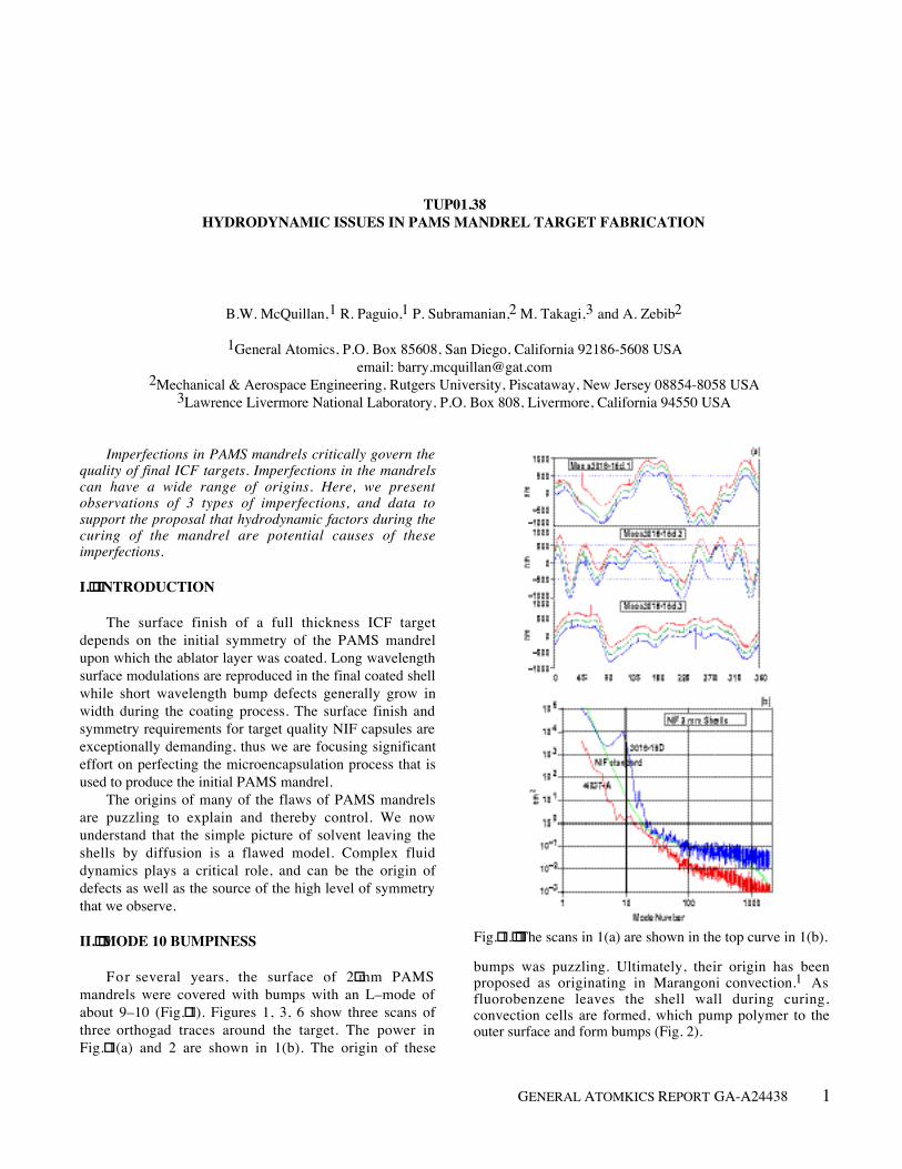
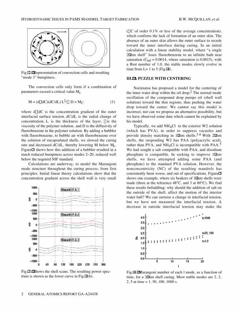
For several years, the surface of 2!mm PAMSmandrels were covered with bumps with an L–mode ofabout 9–10 (Fig.!1). Figures 1, 3, 6 show three scans ofthree orthogad traces around the target. The power inFig.!1(a) and 2 are shown in 1(b). The origin of these
Fig.!1.!!The scans in 1(a) are shown in the top curve in 1(b).
bumps was puzzling. Ultimately, their origin has beenproposed as originating in Marangoni convection.1 Asfluorobenzene leaves the shell wall during curing,convection cells are formed, which pump polymer to theouter surface and form bumps (Fig. 2).
HYDRODYNAMIC ISSUES IN PAMS MANDREL TARGET FABRICATION B.W. MCQUILLAN, et al.
2 GENERAL ATOMICS REPORT GA-A24438
Fig.!2.!!Representation of convection cells and resulting“mode 3” bumpiness.
The convection cells only form if a combination ofparameters exceed a critical value Mc
M = (dg/dC)(dC/dL) L2/h D > MC (1)
where dg/dC is the concentration gradient of the outerinterfacial surface tension, dC/dL is the radial change ofconcentration, L is the thickness of the layer, h is theviscosity of the polymer solution, and D is the diffusivity offluorobenzene in the polymer solution. By adding a bubblerwith fluorobenzene, to bubble air with fluorobenzene overthe solution of encapsulated shells, we slowed the curingrate and decreased dC/dL, thereby lowering M below Mc.Figure!3 shows how this addition of a bubbler resulted in amuch reduced bumpiness across modes 2–20, reduced wellbelow the required NIF standard.
Calculations are underway, to model the Marangonimode structure throughout the curing process, from firstprinciples. Initial linear theory calculations show that theconcentration gradient across the shell wall is very small
Fig.!3.!!Shows the shell scans. The resulting power spec-trum is shown as the lower curve in Fig.!1(b).
(DC of order 0.1% or less of the average concentration),which confirms the lack of formation of an outer skin. Theabsence of an outer skin allows the outer surface to recedetoward the inner interface during curing. In an initialcalculation with a linear stability model, where “a single2!mm shell” loses fluorobenzene to an infinite bath nearsaturation (Cinf = 0.0014, where saturation is 0.0015), witha Biot number of 1.0, the stable modes slowly evolve intime from L= 1 to 5 (Fig.!4).
III.!!A PUZZLE WITH CENTERING
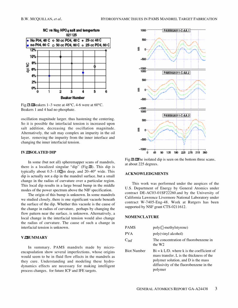
Norimatsu has proposed a model for the centering ofthe inner water drop within the oil drop.2 The normal modeoscillation of the compound drop pumps oil (shell wallsolution) toward the thin regions, thus pushing the waterdrop toward the center. We cannot say this model isincorrect, nor can we propose an alternative possibility, butwe have observed some data which cannot be explained byhis model.
Typically, we add NH4Cl to the exterior W2 solution(which has PVA), in order to suppress vacuoles andprovide density matching in 1!mm shells.3,4 With 2!mmshells, the suspending W2 has PAA (polyacrylic acid),rather than PVA, and NH4Cl is incompatible with PAA.5We had sought a salt compatible with PAA, and disodiumphosphate is compatible. In seeking to improve 1!mmshells, we have attempted adding some PAA (andphosphate) to the standard PVA solution. However, thenonconcentricity (NC) of the resulting mandrels hasconsistently been worse, and out of specifications. Figure!5shows one example, where six beakers of 1!mm shells weremade (three at the reference 48°C, and 3 at 60°C). We findthese results befuddling: why should the addition of salt onthe outside of the shell, affect the motion of the interiorwater ball? We can surmise a change in interfacial tension,but we have not measured the interfacial tension. Adecrease in outside interfacial tension may make the
Fig.!4.!!Marangoni number of each l mode, as a function oftime, for a 2!mm shell curing. Most stable modes are 2, 2,2, 5 at time = 1, 50, 100, 1000 s.
B.W. MCQUILLAN, et al. HYDRODYNAMIC ISSUES IN PAMS MANDREL TARGET FABRICATION
GENERAL ATOMKICS REPORT GA-A24438 3
Fig.!5.!!Beakers 1–3 were at 48°C, 4-6 were at 60°C.Beakers 1 and 4 had no phosphate.
oscillation magnitude larger, thus hastening the centering.So it is possible the interfacial tension is increased uponsalt addition, decreasing the oscillation magnitude.Alternatively, the salt may complex an impurity in the oillayer, removing the impurity from the inner interface andchanging the inner interfacial tension.
IV.!!ISOLATED DIP
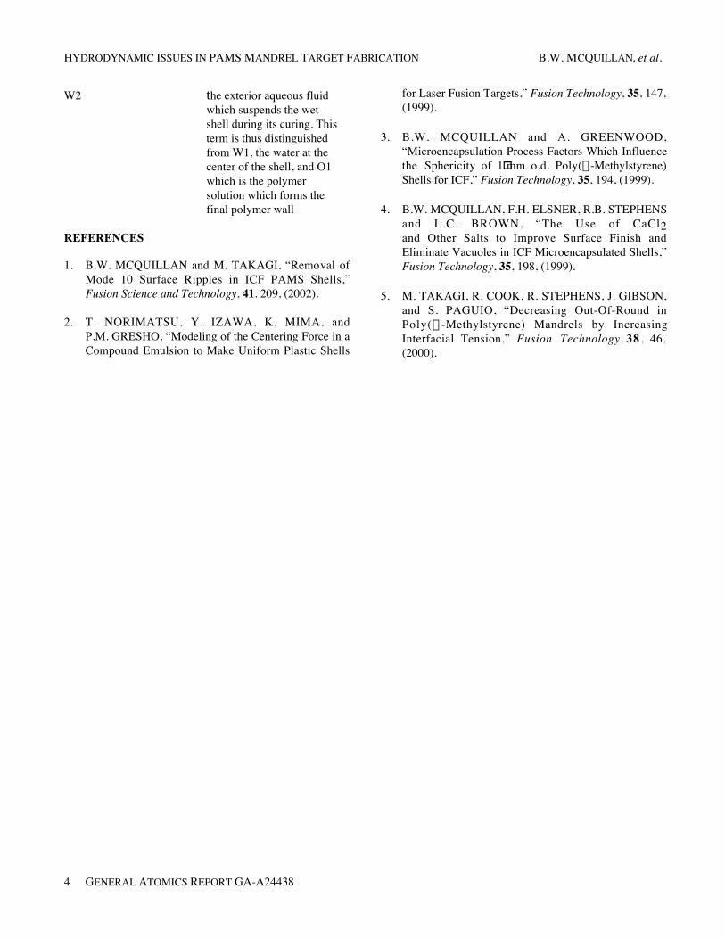
In some (but not all) spheremapper scans of mandrels,there is a localized singular “dip” (Fig.!6). This dip istypically about 0.5–1.0!mm deep, and 20–40° wide. Thisdip is actually not a dip in the mandrel surface, but a smallchange in the radius of curvature over a particular region.This local dip results in a large broad bump in the middlemodes of the power spectrum above the NIF specification.
The origin of this bump is unknown. In some mandrelswe studied closely, there is one significant vacuole beneaththe surface of the dip. Whether this vacuole is the cause ofthe change in radius of curvature, perhaps by changing theflow pattern near the surface, is unknown. Alternatively, alocal change in the interfacial tension would also changethe radius of curvature. The cause of such a change ininterfacial tension is unknown.
V.!!SUMMARY
In summary, PAMS mandrels made by micro-encapsulation show several imperfections, whose originswould seem to be in fluid flow effects in the mandrels asthey cure. Understanding and modeling these hydro-dynamics effects are necessary for making intelligentprocess changes, for future ICF and IFE targets.
Fig.!6.!!The isolated dip is seen on the bottom three scans,at about 225 degrees.
ACKNOWLEDGMENTS
This work was performed under the auspices of theU.S. Department of Energy by General Atomics undercontract DE-AC03-01SF22260.and by the University ofCalifornia Lawrence Livermore National Laboratory undercontract W-7405-Eng-48. Work at Rutgers has beensupported by NSF grant CTS-0211612.
NOMENCLATURE
PAMS poly(a-methylstyrene)PVA poly(vinyl alcohol)Cinf The concentration of fluorobenzene in
the W2Biot Number Bi = k L/D, where k is the coefficient of
mass transfer, L is the thickness of thepolymer solution, and D is the massdiffusivity of the fluorobenzene in thepolymer
HYDRODYNAMIC ISSUES IN PAMS MANDREL TARGET FABRICATION B.W. MCQUILLAN, et al.
4 GENERAL ATOMICS REPORT GA-A24438
W2 the exterior aqueous fluidwhich suspends the wetshell during its curing. Thisterm is thus distinguishedfrom W1, the water at thecenter of the shell, and O1which is the polymersolution which forms thefinal polymer wall
REFERENCES
1. B.W. MCQUILLAN and M. TAKAGI, “Removal ofMode 10 Surface Ripples in ICF PAMS Shells,”Fusion Science and Technology, 41. 209, (2002).
2. T. NORIMATSU, Y. IZAWA, K, MIMA, andP.M. GRESHO, “Modeling of the Centering Force in aCompound Emulsion to Make Uniform Plastic Shells
for Laser Fusion Targets,” Fusion Technology, 35, 147,(1999).
3. B.W. MCQUILLAN and A. GREENWOOD,“Microencapsulation Process Factors Which Influencethe Sphericity of 1!mm o.d. Poly(a-Methylstyrene)Shells for ICF,” Fusion Technology, 35, 194, (1999).
4. B.W. MCQUILLAN, F.H. ELSNER, R.B. STEPHENSand L.C. BROWN, “The Use of CaCl2and Other Salts to Improve Surface Finish andEliminate Vacuoles in ICF Microencapsulated Shells,”Fusion Technology, 35, 198, (1999).
5. M. TAKAGI, R. COOK, R. STEPHENS, J. GIBSON,and S. PAGUIO, “Decreasing Out-Of-Round inPoly(a -Methylstyrene) Mandrels by IncreasingInterfacial Tension,” Fusion Technology, 38 , 46,(2000).