hydrodynamically confined flow devices - intech - open science
TRANSCRIPT

8
Hydrodynamically Confined Flow Devices
Alar Ainla, Gavin Jeffries and Aldo Jesorka* Chalmers University of Technology, Göteborg,
Sweden
1. Introduction
Microfluidic technology is a fast growing branch of microdevice development, which has its
origin in the dot matrix printing principle demonstrated by R. Elmqvist of the German
Siemens AG in the 1950s. In this “ink jet” concept, droplets are formed from a stream of ink
ejected from a microscale opening. The drop formation is characterized by a stream breakup
mechanism discovered nearly a century earlier by Lord Rayleigh1. It took another twenty
years from the initial proof of principle until the first commercial inkjet printer was
produced and marketed by IBM in the mid 1970s. It has to be noted that the inkjet printer
technology remains the most successful commercial microfluidic application to date.
However, advances in the application of microflow technology were also made in other
fields, most notably in chemistry and the biosciences. Microfluidic devices for handling
nano- and picolitre volumes of liquids are now commonplace, and have proven to
greatly benefit molecular biology, proteomics, DNA analysis, and various branches of
analytical chemistry. Microfluidic devices are also frequently used to address the
chemical foundations of technological applications, which is often difficult to achieve on
the bulk scale. The desire to confine chemical and biological functions to the micrometer
sized channels arose mainly from the need to reduce sample size and reagent
consumption and to lower fabrication costs, integrate a large number of processing steps,
such as mixing, chemical binding and purification, and facilitate interfacing and
handling. The drive to integrate various on-chip detection schemes with sample
handling and analyte separation led to a new highly integrated class of microfluidic
devices, the micro-total analysis systems (µTAS). Such devices require typically between
100 nl and 10 μl of liquid for processing and analysis. The dynamics of liquid flows in
microscale channels is quite complex, and deviates significantly from macroscopic
flows2. The major differences between microscale and macroscopic (bulk) fluid flows
arise from the large surface to volume ratio, low Reynolds number effects and
noncontinuum molecular effects. In addition, multiscale and multiphysics effects have to
be considered when simulating microflow phenomena3. As microflows are typically
laminar, several streams of fluid can flow in parallel in the same channel without
converging into each other. Diffusion dominates the exchange of molecular species in
those parallel streams, and equilibration is achieved on a short timescale of seconds to
*Corresponding author
www.intechopen.com

Hydrodynamics – Theory and Model
168
minutes. This feature allows for diffusional mixing as the sole mode of transport
between flows, and can be used to control separation and the progress of chemical
reactions. Flows can be generated by electroosmotic pumping, capillary forces, or by
means of applying pressure. Each method has advantages and disadvantages; a practical
choice depends on the type of sample, the interfacing requirements and the detection
principle desired.
Closed-channel microfluidics can rightfully be considered an established, often highly beneficial method for the processing of small sample volumes for applications within biology, chemistry and biotechnology, with high potential to reach into medicine and diagnostics in the near future. Recent technological developments, such as droplet microfluidics, and low-cost production processes are expected to facilitate this development further. The fabrication of microfluidic devices is generally achieved through top-down micro-construction techniques: traditional lithography of quartz, glass and silicon substrates, soft lithography using various polymers, and layered (laminate) technologies, for example utilizing paper or polymeric thin films4.
However, in many important instances closed channel microfluidic device are not a suitable solution, even though sample size and other requirements are in the optimal range. For example, it is difficult or often impossible to interact with surfaces or surface adhered objects, such as single cells or tissue slices. Cells have to be introduced into the channel structure, manipulated to the desired position, kept alive under controlled conditions, and exchanged or removed from the channels. Growing cells in microscale channels is subject to limits imposed by the diffusion-dominated material transport in confined volumes, which can have a detrimental effect on cell growth. Moreover, the spatially controlled delivery of small amounts of liquid to a surface, for instance in order to create defined patterns or achieve surface functionalization, pushes closed channel designs to the limit. An elegant practical solution to many problems is offered by a new microflow concept, which uses a dynamically defined open volume principle rather than pre-defined, closed channels for confinement and delivery of fluids.
2. Hydrodynamically confined flow devices
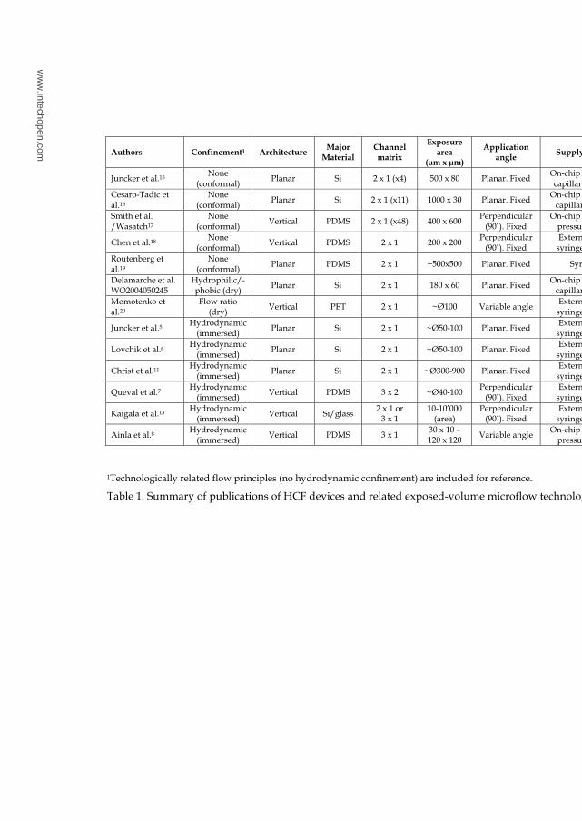
Hydrodynamically confined flow (HCF), also occasionally referred to as hydrodynamically confined microflow (HCM) devices, are a modern class of microfluidic flow cells, where a small, moving volume of fluid is spatially confined within another, significantly larger fluid volume. The two liquids are physically in contact, separated only by means of a dynamically created virtual boundary. This boundary can be achieved, for example, by two adjacent microflow channels. One channel serves as injection port or outlet (positive pressure), where liquid is introduced into an open volume, and one as aspiration port or inlet (negative pressure), through which liquid is removed. As some surrounding liquid is also being removed from the fluid bulk, a laminar flow envelope results, which confines the liquid between inlet and outlet. Material transport across the boundary is only possible by diffusion. There is only a relatively small number of HCF devices present in the literature, as this novel class of devices has just started to progress into a research area5-14. The contributions of the different research groups are summarized in table 1. For reference, the technologically related devices, which do not employ hydrodynamic confinement, but feature similar channel arrangements and in/out-flows, creating an exposed liquid volume,
www.intechopen.com

Hydrodynamically Confined Flow Devices
169
are included. They can be considered milestones in the development of the HCF devices, and have their own interesting set of applications, for example in electrochemical surface analysis and in parallel assay technology. Highlighted in the table are geometries, channel arrangement, interface and positioning, and the major material. Typical materials are silicon, glass and polymers, most dominating the silicone elastomer poly(dimethyl siloxane), or PDMS.
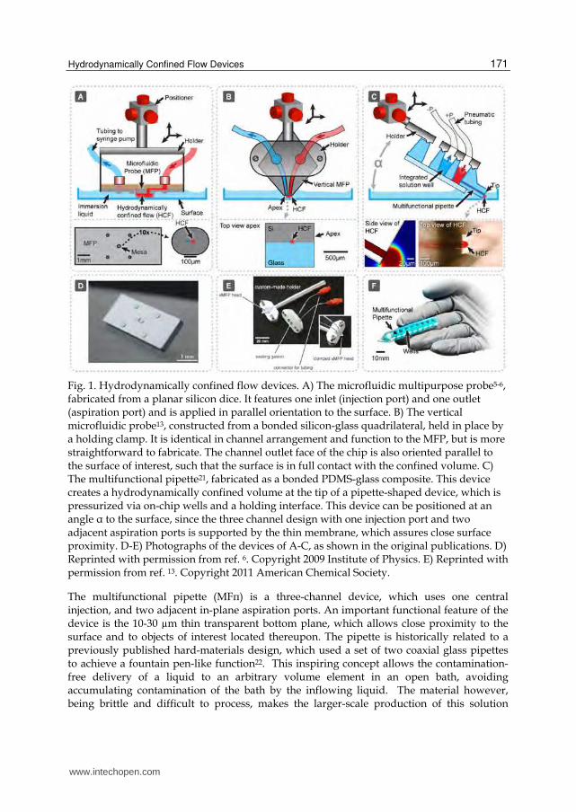
Figure 1 shows three example concepts of hydrodynamically confined flow devices, the microfluidic multipurpose probe (MFP), the vertical microfluidic probe (vMFP), and the multifunctional micropipette (MFπ), pioneered by two different research groups. Figure 1(A), depicts schematically the microfluidic probe developed by Junker et al. from IBM. From design and idea, but not necessarily from principle, it can be considered a descendant of IBM’s classic ink jet printing technology5. The device consists of a flat silicon plate of cm2 dimensions with two central orifices on a central mesa-like structure, one for solution inlet and one for outlet (with respect to the open bath). For operation, it is arranged parallel to the surface of interest, and submerged in a shallow bath of fluid. It is held at a fixed distance of a few micrometers by four protruding posts. The plate is interfaced by supply tubes, and can be positioned by a micromanipulation device. When positive pressure is applied to the injection port, and negative pressure (moderate vaccum) to the aspiration port, a stream of liquid moves through the bath and creates a defined volume of fluid, which is spatially confined to the region between surface and silicon mesa. The red color represents the inflow (injection) into, and the blue color the outflow (aspiration) from the open volume. A small part of the open volume is also drawn into the outflow channel. It has to be noted that this open volume component is typically the major share of the total inflow volume, which is fundamental to define the hydrodynamic confinement. In this two-cannel device, the close proximity of the surface is preferred to prevent fluid from escaping the confinement. The lower panel in fig. 1A displays the bottom plate of the device together with an enlarged view of the mesa.
Figure 1D shows a photograph of this device, as presented in the original publications. In fig. 1B a structural modification of the MFP is schematically displayed, termed the vertical microfluidic probe (vMFP)13. The large silicon bottom plate of the earlier design has been replaced by a rhombic Si/glass composite with a flat, polished tip, which can be clamped and interfaced to the supplies by a matching sealing holder. In order to achieve efficient interaction of the out-flowing liquid with the surface, this design still requires parallel alignment of the channel outlet plane with the surface. The generation of the confined volume is commensurate to the MFP, fluid circulation is also achieved through tubing and syringe pumps. Fig. 1E is a series of photographs, showing the two individual holder parts, the rhombic silicon chip and the fully assembled device.
Both MFP and vMFP are fabricated from silicon or bonded silicon/glass. These devices are optically intransparent and can be used under a microscope only with limitations. Even more disadvantageous is the vertical positioning in upright microscopes, which limits the compatibility with microscopy stations to some extent. The vertical probe eliminates some of the problems, since it is rather small and partly transparent. Inverse microscopes are accessible, even though a means of precise positioning might be advisable, such as a motorized stage. The solution depicted in Fig 1C overcomes these disadvantages by both using a transparent material combination and a design which allows angled positioning.
www.intechopen.com
H
yd
rod
yn
am
ics –
Th
eo
ry a
nd
Mo
de
l
170
1Technologically related flow principles (no hydrodynamic confinement) are included for reference.
Table 1. Summary of publications of HCF devices and related exposed-volume microflow technologies.
ww
w.intechopen.com
Hydrodynamically Confined Flow Devices
171
Fig. 1. Hydrodynamically confined flow devices. A) The microfluidic multipurpose probe5-6, fabricated from a planar silicon dice. It features one inlet (injection port) and one outlet (aspiration port) and is applied in parallel orientation to the surface. B) The vertical microfluidic probe13, constructed from a bonded silicon-glass quadrilateral, held in place by a holding clamp. It is identical in channel arrangement and function to the MFP, but is more straightforward to fabricate. The channel outlet face of the chip is also oriented parallel to the surface of interest, such that the surface is in full contact with the confined volume. C) The multifunctional pipette21, fabricated as a bonded PDMS-glass composite. This device creates a hydrodynamically confined volume at the tip of a pipette-shaped device, which is pressurized via on-chip wells and a holding interface. This device can be positioned at an angle α to the surface, since the three channel design with one injection port and two adjacent aspiration ports is supported by the thin membrane, which assures close surface proximity. D-E) Photographs of the devices of A-C, as shown in the original publications. D) Reprinted with permission from ref. 6. Copyright 2009 Institute of Physics. E) Reprinted with permission from ref. 13. Copyright 2011 American Chemical Society.
The multifunctional pipette (MFπ) is a three-channel device, which uses one central injection, and two adjacent in-plane aspiration ports. An important functional feature of the device is the 10-30 µm thin transparent bottom plane, which allows close proximity to the surface and to objects of interest located thereupon. The pipette is historically related to a previously published hard-materials design, which used a set of two coaxial glass pipettes to achieve a fountain pen-like function22. This inspiring concept allows the contamination-free delivery of a liquid to an arbitrary volume element in an open bath, avoiding accumulating contamination of the bath by the inflowing liquid. The material however, being brittle and difficult to process, makes the larger-scale production of this solution
www.intechopen.com
Hydrodynamics – Theory and Model
172
delivery device more than problematic. There are also severe drawbacks with respect to applying the needle-like device in close proximity to a surface. Small errors in positioning can instantly break the delicate assembly. In contrast, the MFπ tip is (currently) entirely made from PDMS elastomer, and can be repeatedly brought in contact with the surface without loss of integrity. The flow profile generated by the three-channel arrangement is comparable to the one provided by the coaxial fountain pen. It allows free-standing operation, since no fluid can escape the hydrodynamic confinement within the recirculation zone created at the very tip. Direct contact to the surface is no longer required. The lower panel in fig. 1A shows a side view (FEM simulation of the concentration profile at the channel outlet) and a top view, which visualize the three channel arrangement by means of a red colored liquid. The device further features on-chip fluid reservoirs. Externally it only requires pressure supplied through an interface/holder. This pipette opens interesting opportunities in biosciences, pharmacology and clinical research, since the device can be co-located with additional probing equipment under ordinary microscopes, and allows highly localized interaction of a chemical or biochemical stimulant with surface-adhered cells and tissue in dish cultures.
All three hydrodynamically confined flow devices have individual design strengths, which make them attractive research instruments in particular application areas. Each of the concepts requires a different set of microfabrication techniques for fabrication and assembly, owing to the materials requirements and most likely, availability of processing equipment and expertise. In the following section we give an illustrated overview over the three different fabrication routes and compare their performance.
3. Fabrication strategies
3.1 The microfluidic probe
The fabrication of the MFP follows a multi-step fabrication route based on traditional silicon processing techniques (figure 2). Bonding to a PDMS block is employed to obtain closed channel structures. The original publication reports use of double-side-polished silicon wafers as starting material. Three UV-photolithography steps, targeting both sides of the wafer, and two deep-reactive-ion etching (DRIE) steps are required to fabricate the relatively complex structure. After initial photolithography, the top channel structure is etched into the wafer (figure 2, left panel). The wafer is then turned upside-down, and a protective silicon dioxide layer is deposited, photolithographically patterned and etched to pre-define the bottom mesa and the support pillars. A third photolithography step follows to place two orifices for the following first DRIE step (figure 2, middle panel). After removal of the resist layer, and ashing resist residue, a second DRIE step on the same wafer side produces the bottom mesa and the support pillars. The top channel structure is then activated by an oxygen plasma, and bonded to a PDMS slab in order to close the device and provide an interface to the liquid supply lines.
The elastomeric rubber not only tightly bonds chemically to the silicon surface, it also allows for pushing thin plastic tubes or fused silica capillaries into stamped-out holes, effectively sealing the tubes without additional measures.
Chips with a surface area of about 3 x 7 mm2 are diced, interfaced with tubing and placed in a holding clamp for application to desired surfaces. Further details on the fabrication
www.intechopen.com

Hydrodynamically Confined Flow Devices
173
strategy are provided in a previous publication of the authors on two-level microfluidic networks for patterning surfaces23.
Fig. 2. Schematic fabrication procedure for the MFP, consisting of essentially three
photolithography and two DRIE steps. Double-side-polished silicon wafers are used for
the procedure. The left panel depicts the fabrication of the upper side of the chip,
producing the horizontal channels for liquid supply to the through holes. The middle
panel shows the SiO2 fabrication to define the locations for mesa and support pillars, as
well as the first DRIE step to open the vertical channels. Two additional photolithography
steps are required. The right panel shows the removal of resist, and the second DRIE step
in order to fabricate the bottom geometries. Also shown are the interfacing strategy by
means of tubing or fused silica capillaries embedded in a PDMS lid layer, and a three-
dimensional representation of the chip, with slightly exaggerated bottom features.
Injection and aspiration port are depicted in red and blue, respectively, according to
figure 1.
3.2 The vertical microfluidic probe
The vMFP has been designed based upon the microfluidic probe discussed above, in
order to overcome critical inadequacies with respect to practical application and
implementation of the original device concept. The MFP, being functionally closely
related to the ink-jet print head, is associated with a number of systematic and
fabrication related problems, which have been addressed by the authors in their latest
study13. They successfully address artifacts of the earlier technology, including the
inability to pattern surfaces in liquid environments, and limitations imposed by the
physics of liquid ejection, which restrict the range of geometrically defined confinements
of chemicals on surfaces. Above all, the fabrication of the vMFP has been largely
simplified by eliminating photolithography steps and introducing some more facile, yet
unconventional fabrication steps. Figure 3 depicts the full procedure. A disadvantage in
comparison to the MFP is the limited flexibility with respect to the number and
arrangement of channels.
www.intechopen.com
Hydrodynamics – Theory and Model
174
vMFP heads are designed as silicon/glass hybrids, with the channel structures etched as
20 mm deep groves into the 400 μm thick silicon side. A slightly thicker glass slide of
identical dimensions is anodically bonded to the silicon in order to obtain closed three
dimensional channels. Since the channels are no longer located on the planar silicon face,
but on one of the two sharp points of a rhombic chip geometry, which requires a finish
by lapping and polishing, the risk of contamination of the channels by silicon dust
particles had to be addressed. A solution to the problem was achieved through filling the
channels with a low melting point wax prior to the mechanical polishing. The wax has to
be removed afterwards by submerging the device in an organic solvent, such as heptane,
for several hours. The authors do not detail the performance of this unconventional
fabrication step, for example whether there is a wax film remaining on the channel walls,
if rinsing steps are of advantage, or other details. The left panel in fig. 3 shows the initial
procedure, including the first photolithography step, which defines the channel groves.
The middle panel depicts the second photolithography (implicit, see figure 2), wax
filling, and dicing. Lapping, polishing of the channel edges and wax removal is shown in
the right panel, together with a perspective drawing of the polished tip of the device. It is
clear that this procedure requires less instrument time and processing effort, in
comparison to the fabrication scheme for the MFP, but wax filling and solvent treatment
raises questions with regard to reproducibility and remaining traces of the wax in the
channels after fabrication. From a functional point of view, this device is clearly easier to
interface and integrate. It has a smaller footprint of approximately 1 mm2, which suggest
better positioning ability, even though the need for parallel alignment of the channel exit
plane to the surface makes it difficult to integrate with conventional light or confocal
microscopes. The original publication therefore includes a schematic drawing of the
recommended setup for the probe, which includes a two-axis positioning table and tilt-
adjustment mechanics. Also discussed are extensions to the flow circuitry, for example a
three channel design which features two aspiration channels and is thereby similar to the
MFπ in arrangement. The authors introduce concepts of on-chip filter structures,
designed to eliminate the threat of inflow-channel clogging by aspirated material from
the surrounding volume.
Design, fabrication and advanced features of the vMFP represent a significant step forward
from the MFP. The vMFP is a versatile research device, which unfortunately still requires a
specialized stage for mounting and operation. This is particularly important, as the effective
surface distance must be set as small as 1-30 µm in order to successfully superfuse surface
structures. However, the authors rightfully point out that the in-plane design allows for
most simple integration of one or more functional elements such as resistive heaters, surface
printed electrodes, or sensors. They have also demonstrated that by means of side channels,
immersion liquid dispensing can be integrated into the probe design. The probe clearly
meets several of the challenges imposed upon dynamic fluid confinement devices, but
unsolved issues remain. Important concerns arise with respect to integration with existing
microscopy stations, which is particularly pressing when live cells and tissue cultures are
under investigation, as well as to the somewhat limiting parallel arrangement of the channel
exit plane towards the surface. These limitations are probably not easily addressable, as the
material and integration options are the fundamental characteristics of these HCF chip
variants.
www.intechopen.com

Hydrodynamically Confined Flow Devices
175
Fig. 3. Fabrication procedure for the vMFP, comprising two photolithography and DRIE steps to define the channels and vias, bonding and polishing. The left panel depicts the first photolithography and DRIE steps performed on a silicon wafer, which define the channel groves. The middle channel depicts the opening of vias by a second photolithography/DRIE round. The second PL (cf. fig. 2) is not shown in detail. Subsequently a glass wafer is anodically bonded onto the silicon, and the channels are closed with a low melting point wax, which is drawn into the structure by capillary forces. In the next step, as shown in the right panel, the bonded wafer is diced, and the apex of the rhombic chip is mechanically lapped and polished. Typically, several stacked dices are polished at the same time. The final step involves removal of the wax by submerging the dices in an organic solvent, which dissolves the hydrocarbon based filling. The left panel also schematically shows a perspective of the flat apex with the channels. The shape and dimensions of the chip are apparent from the photograph of the full device in fig. 1D.
3.3 The multifunctional pipette
With replica molding in PDMS a different approach was chosen to fabricate the third type of HCF device, the multifunctional pipette8. The device was designed to utilize three-channel recirculation, with two aspiration ports and one injection channel. The injection zone forms a free-standing dynamic fluid boundary, which prevents the escape of injected fluid and thus eliminates cross-contamination. With on-chip solution wells and a network of flow channels defined by the replica molding master, it allows complex chemical signals to be generated and applied at cellular and sub-cellular dimensions. The most important design feature is a thin PDMS membrane bottom plane of the device, fabricated by spin-coating of a pre-mixed PDMS membrane, and subsequent curing and plasma-bonding. The distinct advantage of replica molding, a form of soft-lithography, is the simple fabrication protocol, which does not even strictly require clean-room conditions. Soft lithography, in brief, employs a liquid pre-polymer and a fabrication master, which is typically a silicon wafer with the channel structure and alignment
www.intechopen.com
Hydrodynamics – Theory and Model
176
marks microfabricated on the surface. Such a master can be produced by photolithography, typically employing a negative resist, or by DRIE if a very large number of replication cycles desired. Photoresist tends to lift off the surface after several cycles, but allows more rapid changes in master design. The choice of pre-polymer includes a number of possible materials, most commonly a mixture of silicon polymers and a cross-linking catalyst. The multifunctional pipette fabrication was performed using a commercially available poly-dimethyl siloxane (Sylgard 184 by Dow Corning), which is readily cured above 65 °C, and of low enough viscosity to allow spin coating for membrane manufacture. PDMS mixing, casting and curing was carried out in an ambient environment in a laminar flow hood, which can be placed in a standard chemical laboratory. Figure 4 illustrates the fabrication procedure. PDMS is mixed from two components and filled into a steel or plastics chamber in order to produce the top part of the pipette, including the on chip wells for solution storage and supply. The chamber consists of a top and bottom part, and is designed to minimize the entrapment of air bubbles. The bottom part of the chamber holds the fabrication master, defining the channel structures, typically for up to 20 pipettes. The resulting PDMS slab is ready to be bonded to the thin bottom layer, which will seal the channel groves and define the minimum distance of the channels to the surface. The membrane is spin coated onto a surface-treated (anti-adhesion hydrophobization) silicon wafer. Both the membrane-carrying wafer and the PDMS-filled chamber are exposed to elevated temperature (95 °C for 1 hour), which cross-links the PDMS pre-polymer and forms an elastomeric soft-solid (fig. 4, left panel). The PDMS slab is removed from the chamber, and the well bottoms are stamped out with a sharp ø 1mm hole puncher. The slab is subsequently plasma bonded to the membrane-carrying wafer to form an array of devices, which is peeled off and separated into individual pieces. The tip of each pipette tip is finally cut vertically with microscopic precision along the cutting marks defined in the PDMS structure, opening the channels (fig. 4, middle panel). To stabilize the device structure, a 1 mm thick borosilicate microscope glass cover slip, cut to pipette dimensions of approximately 8.5 x 54 mm, is plasma-bonded to the bottom of the device. The right panel shows these final steps together with a schematic perspective of the pipette tip with the channel exit region.
This soft lithography based fabrication process is by far the least complex of the three
fabrication routes presented. Of distinct advantage are a) the on-chip wells, which
drastically reduce dead volume and facilitate handling and interfacing, and b) the
possibility to incorporate complex microfluidic circuitry into the pipette, such as mixers,
gradient generation and fluid switching stages. For most purposes, the MFπ is clamped in a
metal or plastic pressure manifold, which can be combined with a holding arm to interface
to micromanipulation hardware. The free standing pipette is typically applied at an angle
(cf. fig. 1), allowing direct integration with common microscope setups, for example
brightfield upright or inverse microscopy stations.
Table 2 summarizes several essential fabrication requirements, design characteristics and
application features for direct comparison. Currently, each of the technologies has a number
of functional advantages, but also up-scaling limitations, which can most likely be
addressed in the future. For example, the strong benefits of the MFπ with respect to cheap
material and facile production without dedicated cleanroom environment have to be traded
www.intechopen.com

Hydrodynamically Confined Flow Devices
177
off against the inherently limited compatibility of the soft PDMS polymer towards organic
solvents. This disadvantage might not be overly limiting in studies of biological material
such as single cells and tissue, since buffered aqueous solutions rather than organic media
are typically used in these experiments. It is clear that the use of other materials is possible,
and will become subject to future investigation. The MFP allows for arbitrary channel
positioning and channel shapes, as the openings are generated by DRIE, which gives a
certain advantage over the other two concepts, in particular the MFπ, which is currently
restricted to linear arrays of rectangular channels.
Fig. 4. Fabrication procedure for the MFπ. The soft lithography procedure starts from a
PDMS pre-polymer mixture, which is filled into a molding chamber. The master is a silicon
wafer with the channels embossed, typically generated by SU-8 photolithography. This
yields a PDMS slab with imprinted channel groves, which need to be closed to obtain a
functioning device. For that purpose a thin PDMS membrane is fabricated by spin coating
(left panel). The PDMS slab is removed from the molding form, and oxygen plasma bonded
to the membrane. Holes are punched through the structure in order to connect the channels
with the well interior, and the tip is cut off after alignment under a microscope (middle
panel). A glass support is finally bonded to the underside, leaving only a 5 mm end at the
pipette tip uncovered (right panel). The bottom part of the right panel also shows
schematically the pipette tip obtained by the fabrication procedure. The thin membrane at
the underside of the device defines the distance to the surface.
www.intechopen.com

Hydrodynamics – Theory and Model
178
4. Application examples
Each of the devices discussed above was conceptualized to provide one or more solution(s)
to technological challenges, and to make processes or scientific experiments feasible which
were previously difficult or impossible to perform. While strongly interrelated in principle,
the differences in design and implementation necessarily assign each device its own range
of applications. While the silicon based probes are useful mainly for chemical surface
processing, such as staining, etching or decorating surface areas or surface-attached objects,
even cell cultures, the MFπ has its strong side in single cell handling, superfusion and direct
or indirect support of other probing or sensing devices. Figure 5 shows application
examples for all three devices. In the original publication5, several different application
examples were provided. Continuous variation of the scanning velocity of the MFP was
utilized to create local concentration gradients, useful for example for patterning surfaces
with biomolecules, such as proteins. In another example, a MFP with 24 µm separated 40×40
µm apertures was positioned 15–20 µm above a substrate covered with fixed NIH3T3
fibroblast cells, and the cells were exposed to a solution of a membrane soluble fluorescent
dye (fig. 5A). The selective detachment and collection of a single living cell from a surface
was also demonstrated.
The beneficial use of the MFP is not only limited to experiments in cell biology and
related areas, but might also find application in chemistry, micro fabrication and surface
processing. Maskless lithography is an efficient technique for patterning or modifying
planar surfaces with micrometer resolution. Fig. 5B shows an example where a MFP heads
was used to write a hole pattern into a 3 µm thick AZ4562 (positive) photoresist layer,
dispensing AZ400K developer as process liquid from the MFP. The shape of the spots is
here determined by the geometry of the HCF region. In fig. 5C the application of the
vMFP for localized chemistry on live cell cultures is demonstrated. Selected surface areas
were treated with hypochlorite solution by means of the probe. The procedure chemically
destroys the cells, which is apparent from the morphological changes
(shrinkage/detachment), and can be additionally visualized with trypan blue solution,
which selectively stains dead cells 13. Fig. 5D shows an example of simultaneous use of the
MFπ and an additional probe, here a carbon fiber microelectrode, used to electroporate
single cells for substance delivery. In the experiment the pipette re-circulates a solution of
a compound which cannot penetrate the cell boundary, unless pores are opened in the
membrane. This pore opening is achieved by applying an electrical pulse via a co-
localized electrode. The MFπ ensures delivery of the fluorescent material only to the
selected cell, and allows for repeated experiments on many different cells in the same
culture.
The original publication presented a number of additional applications for the concept, including dose response determinations of pharmacological compounds on selected cells, cell-protrusion formation by chemical means and measurements of ion channel activities on individual cells8. Most of these application examples demonstrate clearly the potential of the different HCF devices, as they address experimental problems in the biosciences or fabrication related requirements that could not be conveniently solved by traditional glass pipette methods, closed channel microfluidic chips or other kinds of microdevice technology.
www.intechopen.com

Hydrodynamically Confined Flow Devices
179
Table 2. Comparison of hydrodynamic flow confinement devices (application and fabrication aspects)
www.intechopen.com
Hydrodynamics – Theory and Model
180
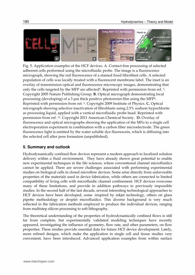
Fig. 5. Application examples of the HCF devices. A. Contact-free processing of selected
adherent cells performed using the microfluidic probe. The image is a fluorescence
micrograph, showing the red fluorescence of a stained fixed fibroblast cells. A selected
population of cells was locally treated with a fluorescent membrane label. The inset is an
overlay of transmission optical and fluorescence microscopy images, demonstrating that
only the cells targeted by the MFP are affected5. Reprinted with permission from ref. 5.
Copyright 2005 Nature Publishing Group. B. Optical micrograph demonstrating local
processing (developing) of a 3 μm thick positive photoresist film using the MFP6.
Reprinted with permission from ref. 6. Copyright 2009 Institute of Physics. C. Optical
micrograph showing selective inactivation of fibroblasts using 2.5% sodium hypochlorite
as processing liquid, applied with a vertical microfluidic probe head. Reprinted with
permission from ref. 13. Copyright 2011 American Chemical Society. D. Overlay of
fluorescence and optical micrographs showing the application of the MFπ to a single cell
electroporation experiment in combination with a carbon fiber microelectrode. The green
fluorescence light is emitted by the water soluble dye fluorescein, which is diffusing into
the selected cell after pore formation (unpublished).
5. Summary and outlook
Hydrodynamically confined flow devices represent a modern approach to localized solution delivery within a fluid environment. They have already shown great potential to enable new experimental techniques in the life sciences, where conventional channel microfluidics cannot be applied. There are severe challenges associated with performing experimental studies on biological cells in closed microflow devices. Some arise directly from unfavorable properties of the materials used in device fabrication, while others are connected to limited compatibility of living cells with microfluidic channel confinement. HCF devices overcome many of these limitations, and provide in addition pathways to previously impossible studies. In the second half of the last decade, several interesting technological approaches to HCF devices have been developed, some -inspired by inkjet technology, others on glass pipette methodology or droplet microfluidics. This diverse background is very much reflected in the fabrication methods employed to produce the individual devices, ranging from multistep silicon processing to soft lithography.
The theoretical understanding of the properties of hydrodynamically confined flows is still far from complete, but experimentally validated modeling techniques have recently appeared, investigating the influence of geometry, flow rate, and other parameters, on flow properties. These studies provide essential data for future HCF device development. Lately, more refined designs, which make the application in single cell and tissue studies very convenient, have been introduced. Advanced application examples from within surface
www.intechopen.com

Hydrodynamically Confined Flow Devices
181
processing, pharmacology, membrane protein science and drug delivery have already emerged. They also indicate, as is expected, that the trend moves towards integration of more and more complex fluid processing functionality, including mixing, multiplexing, and diluting capacities, into the devices. These new generation devices are promising to become routine tools in bioscience research areas where single cell and tissue cultures are probed. There is also a strong possibility that the re-circulated fluid stream can be on-chip processed and analyzed for minute amounts of chemicals released from the stimulated cells and slices, a scenario which is tightly coupled to the progressively improving sensitivity of bioanalytical techniques. In order to support this development, the current microfabrication technologies employed to produce HCF devices have to be developed accordingly. The difficulties and bottlenecks, which limit production scale-up, have to be addressed in a timely manner. It can be anticipated that the traditional silicon-based processing methodologies, which are still commonly used, will be largely replaced by more rapid and cost effective processes.
6. References
[1] Strutt, J. W. L. R. Proceedings of the London Mathematical society 1878, 10, 4.
[2] Squires, T. M.; Quake, S. R. Reviews of Modern Physics 2005, 77, 977.
[3] George Karniadakis, A. B., Narayan Aluru Microflows and Nanoflows: Fundamentals and
Simulation Springer: New York, 2005.
[4] Weigl, B. H.; Bardell, R. L.; Cabrera, C. R. Adv. Drug Delivery Rev. 2003, 55, 349.
[5] Juncker, D.; Schmid, H.; Delamarche, E. Nat. Mater. 2005, 4, 622.
[6] Lovchik, R. D.; Drechsler, U.; Delamarche, E. Journal of Micromechanics and
Microengineering 2009, 19, 8.
[7] Queval, A.; Ghattamaneni, N. R.; Perrault, C. M.; Gill, R.; Mirzaei, M.; McKinney, R. A.;
Juncker, D. Lab Chip 2009, 10, 326.
[8] Ainla, A.; Jansson, E. T.; Stepanyants, N.; Orwar, O.; Jesorka, A. Anal. Chem. 2010, 82,
4529.
[9] Perrault, C. M.; Qasaimeh, M. A.; Brastaviceanu, T.; Anderson, K.; Kabakibo, Y.; Juncker,
D. Rev. Sci. Instrum. 2010, 81, 8.
[10] Sun, M.; Fang, Q. Lab Chip 2010, 10, 2864.
[11] Christ, K. V.; Turner, K. T. Lab Chip 2011, 11, 1491.
[12] Cortes-Salazar, F.; Momotenko, D.; Girault, H. H.; Lesch, A.; Wittstock, G. Anal. Chem.
2011, 83, 1493.
[13] Kaigala, G. V.; Lovchik, R. D.; Drechsler, U.; Delamarche, E. Langmuir 2011, 27, 5686.
[14] Tang, Y. T.; Kim, J.; Lopez-Valdes, H. E.; Brennan, K. C.; Ju, Y. S. Lab Chip 2011, 11, 2247.
[15] Juncker, D.; Schmid, H.; Drechsler, U.; Wolf, H.; Wolf, M.; Michel, B.; de Rooij, N.;
Delamarche, E. Anal. Chem. 2002, 74, 6139.
[16] Cesaro-Tadic, S.; Dernick, G.; Juncker, D.; Buurman, G.; Kropshofer, H.; Michel, B.;
Fattinger, C.; Delamarche, E. Lab Chip 2004, 4, 563.
[17] Smith, K. A.; Gale, B. K.; Conboy, J. C. Anal. Chem. 2008, 80, 7980.
[18] Chen, D.; Du, W.; Liu, Y.; Liu, W.; Kuznetsov, A.; Mendez, F. E.; Philipson, L. H.;
Ismagilov, R. F. Proc. Natl. Acad. Sci. U. S. A. 2008, 105, 16843.
[19] Routenberg, D. A.; Reed, M. A. Lab Chip 2009, 10, 123.
www.intechopen.com

Hydrodynamics – Theory and Model
182
[20] Momotenko, D.; Cortes-Salazar, F.; Lesch, A.; Wittstock, G.; Girault, H. H. Anal. Chem.
2011, 83, 5275.
[21] Ainla, A. J., Gavin D. M.; Brune, Ralf; Orwar, Owe and Jesorka, Aldo Lab on a Chip -
Miniaturisation for Chemistry and Biology (in press) 2011.
[22] Feinerman, O.; Moses, E. J. Neurosci. Methods 2003, 127, 75.
[23] Juncker, D.; Schmid, H.; Bernard, A.; Caelen, I.; Michel, B.; de Rooij, N.; Delamarche, E.
Journal of Micromechanics and Microengineering 2001, 11, 532.
www.intechopen.com

Hydrodynamics - Theory and ModelEdited by Dr. Jin - Hai Zheng
ISBN 978-953-51-0130-7Hard cover, 306 pagesPublisher InTechPublished online 14, March, 2012Published in print edition March, 2012
InTech EuropeUniversity Campus STeP Ri Slavka Krautzeka 83/A 51000 Rijeka, Croatia Phone: +385 (51) 770 447 Fax: +385 (51) 686 166www.intechopen.com
InTech ChinaUnit 405, Office Block, Hotel Equatorial Shanghai No.65, Yan An Road (West), Shanghai, 200040, China
Phone: +86-21-62489820 Fax: +86-21-62489821
With the amazing advances of scientific research, Hydrodynamics - Theory and Application presents theengineering applications of hydrodynamics from many countries around the world. A wide range of topics arecovered in this book, including the theoretical, experimental, and numerical investigations on various subjectsrelated to hydrodynamic problems. The book consists of twelve chapters, each of which is edited separatelyand deals with a specific topic. The book is intended to be a useful reference to the readers who are working inthis field.
How to referenceIn order to correctly reference this scholarly work, feel free to copy and paste the following:
Alar Ainla, Gavin Jeffries and Aldo Jesorka (2012). Hydrodynamically Confined Flow Devices, Hydrodynamics -Theory and Model, Dr. Jin - Hai Zheng (Ed.), ISBN: 978-953-51-0130-7, InTech, Available from:http://www.intechopen.com/books/hydrodynamics-theory-and-model/hydrodynamically-confined-flow-devices

© 2012 The Author(s). Licensee IntechOpen. This is an open access articledistributed under the terms of the Creative Commons Attribution 3.0License, which permits unrestricted use, distribution, and reproduction inany medium, provided the original work is properly cited.