hydrogen compression application of the linear motor reciprocating compressor (lmrc) ·...
TRANSCRIPT
Hydrogen Compression Application of the Linear Motor
Reciprocating Compressor (LMRC)
June 6, 2017
Buddy Broerman (PI)Jeff Bennett (Co-PI) Norm Shade
Southwest Research Institute ACI Services
Project ID: PD108This presentation does not contain any proprietary, confidential, or otherwise restricted information

Timeline Barriers
• US DOE: Project Sponsor and Funding
• SwRI: Project Lead• ACI Services: Project Partner &
Cost Share
Partners
Overview
• Total Project Budget: $2,284,553• Total Cost Share: $459,160• Total Federal Share:
$1,825,393• Total DOE Funds Spent*:
$1,091,641* As of 3/31/17 (includes ACI’s funds spent through Feb 2017)
Budget
Barriers TargetsLow CompressorEfficiency
>73% Isentropic Efficiency*
Capital Cost <$240,000 per compressor**
O&M Costs <$4,800 per year*** DOE Project Target** Targets in the 2012 MYRD&D for 2020
Description Date / TimeframeProject Start Date 9/05/14Project End Date 10/04/18Project Duration 4.0 yearsProject Progress 2.5 years
06/06/2017 SwRI H2 Linear Compressor 2

Relevance• Project Objectives:
– Improve isentropic efficiency above 95% by minimizing aerodynamic losses• Low speed• High valve area ratio
– Reduce capital costs to half that of conventional reciprocating compressors by minimizing part count
– Reduce required maintenance by simplifying the compressor design to eliminate common wear items
• BP1: Analyzed and Designed LMRC to be tested in BP2 & BP3
• Current Budget Period (Fiscal Year 2017, BP2):– Fabricated and assembled the LP Stage LMRC– Fabricated/assembled compressor test stand for LP Stage– Testing is planned for near future
06/06/2017 SwRI H2 Linear Compressor 3
Approach / Milestones
06/06/2017 SwRI H2 Linear Compressor 4
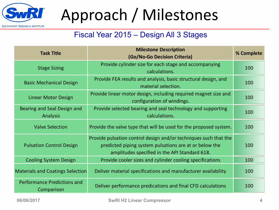
Fiscal Year 2015 – Design All 3 Stages
Milestone Description(Go/No-Go Decision Criteria)
Stage Sizing Provide cylinder size for each stage and accompanying
calculations.100
Basic Mechanical DesignProvide FEA results and analysis, basic structural design, and
material selection. 100
Linear Motor DesignProvide linear motor design, including required magnet size and
configuration of windings. 100
Bearing and Seal Design and Analysis
Provide selected bearing and seal technology and supporting calculations.
100
Valve Selection Provide the valve type that will be used for the proposed system. 100
Pulsation Control DesignProvide pulsation control design and/or techniques such that the
predicted piping system pulsations are at or below the amplitudes specified in the API Standard 618.
100
Cooling System Design Provide cooler sizes and cylinder cooling specifications 100
Materials and Coatings Selection Deliver material specifications and manufacturer availability 100
Performance Predictions and Comparison
Deliver performance predications and final CFD calculations 100
Task Title % Complete
Approach / Milestones
06/06/2017 SwRI H2 Linear Compressor 5
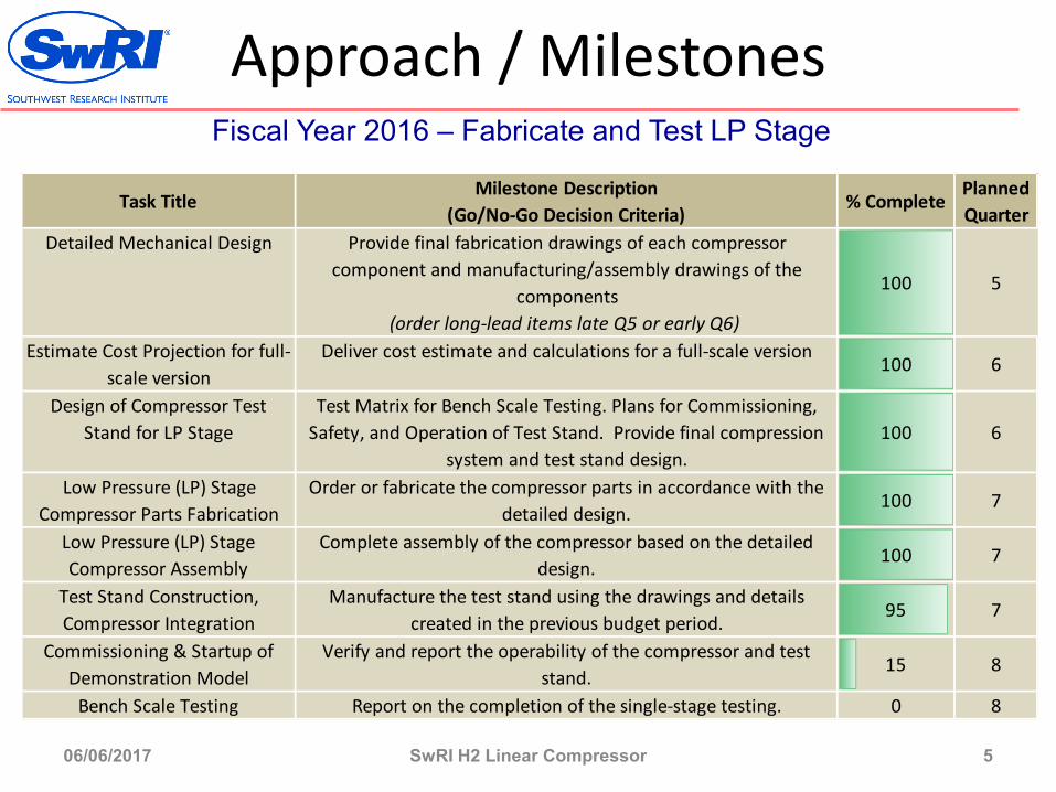
Fiscal Year 2016 – Fabricate and Test LP Stage
Milestone Description(Go/No-Go Decision Criteria)
Provide final fabrication drawings of each compressor component and manufacturing/assembly drawings of the
components(order long-lead items late Q5 or early Q6)
Estimate Cost Projection for full-scale version
Deliver cost estimate and calculations for a full-scale version 100 6
Design of Compressor Test Stand for LP Stage
Test Matrix for Bench Scale Testing. Plans for Commissioning, Safety, and Operation of Test Stand. Provide final compression
system and test stand design. 100 6
Low Pressure (LP) Stage Compressor Parts Fabrication
Order or fabricate the compressor parts in accordance with the detailed design.
100 7
Low Pressure (LP) Stage Compressor Assembly
Complete assembly of the compressor based on the detailed design.
100 7
Test Stand Construction, Compressor Integration
Manufacture the test stand using the drawings and details created in the previous budget period.
95 7
Commissioning & Startup of Demonstration Model
Verify and report the operability of the compressor and test stand.
15 8
Bench Scale Testing Report on the completion of the single-stage testing. 0 8
Task Title % Complete
Detailed Mechanical Design
100
Planned Quarter
5

Accomplishments and Progress: Overall Concept & Test Loop
06/06/2017 SwRI H2 Linear Compressor 6
MRCForecourt Hydrogen Compression
CoolingWater
CoolingWater
IntakeManifold Discharge
Manifold
Hydrogen20 bar
Hydrogen875 bar
Stage 1PR = 3.56Pin = 20
Stage 2PR = 3.56Pin = 71
Stage 3PR = 3.56Pin = 248
Compress H2in 3 stages with 3 LMRCs
Stage 1 Test Loop P&ID
H2
20 bar
H2875 bar
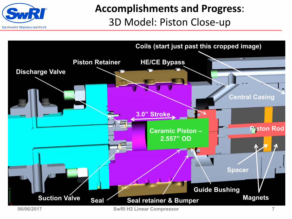
Accomplishments and Progress: 3D Model: Piston Close-up
06/06/2017 SwRI H2 Linear Compressor 7
Ceramic Piston –2.557” OD
Guide BushingSeal Seal retainer & Bumper
Piston Retainer
Suction Valve
Discharge ValveHE/CE Bypass
3.0” Stroke
Central Casing
Magnets
Piston Rod
Spacer
Coils (start just past this cropped image)
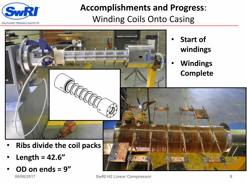
Accomplishments and Progress: Winding Coils Onto Casing
06/06/2017 SwRI H2 Linear Compressor 8
Magnets
Coils
Spacers
• Start of windings
• Windings Complete
• Ribs divide the coil packs• Length = 42.6”• OD on ends = 9”
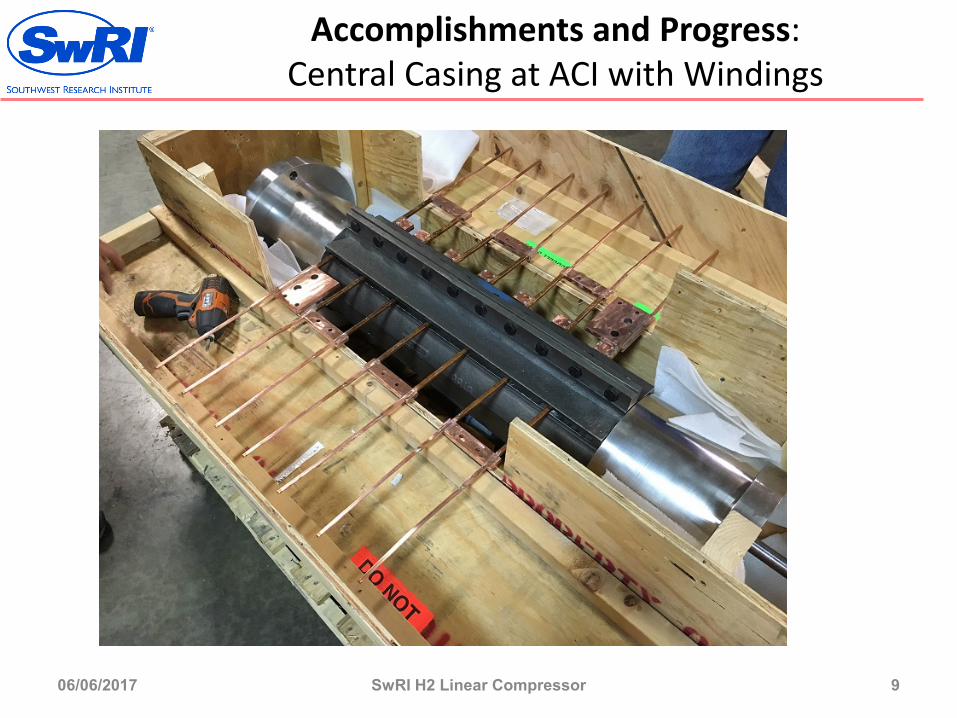
Accomplishments and Progress: Central Casing at ACI with Windings
06/06/2017 SwRI H2 Linear Compressor 9
Magnets
Coils
Spacers

Accomplishments and Progress: Special Tooling Made for Assembling Magnets on Shaft
06/06/2017 SwRI H2 Linear Compressor 10
Magnets
Coils
Spacers
Aluminum assembly fixture used on
assembly press to place one magnet and one
spacer together to form an assembled pair
Aluminum pushing fixture with
magnet/spacer pair being pushed by the hydraulic press into
lower assembly tube
Stainless steel retainer pins inserted to hold upper magnet/spacer pair in place (against the repelling force of the lower magnet) so hydraulic press force
can be relieved and the pushing fixture can be
removed.
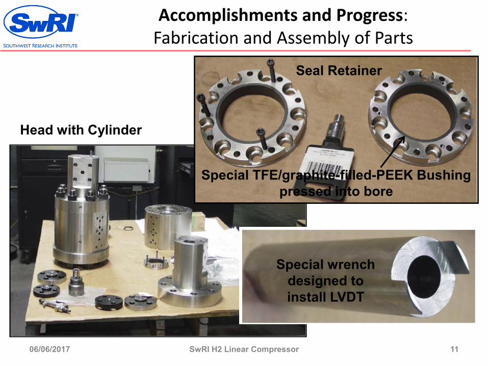
Accomplishments and Progress: Fabrication and Assembly of Parts
06/06/2017 SwRI H2 Linear Compressor 11
Magnets
Coils
Spacers
Special TFE/graphite-filled-PEEK Bushing pressed into bore
Seal Retainer
Special wrench designed to install LVDT
Head with Cylinder
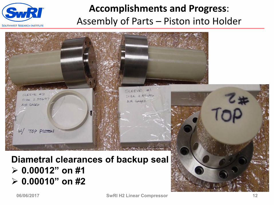
Accomplishments and Progress: Assembly of Parts – Piston into Holder
06/06/2017 SwRI H2 Linear Compressor 12
Magnets
Coils
Spacers
Diametral clearances of backup seal 0.00012” on #1 0.00010” on #2
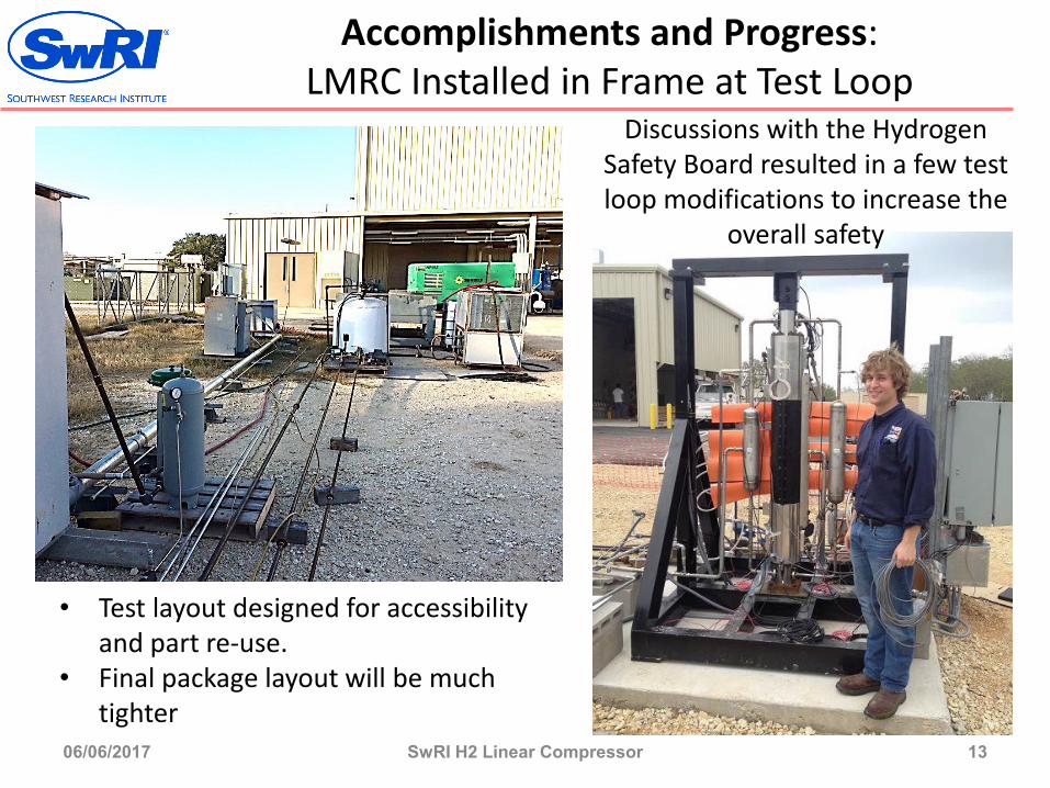
Accomplishments and Progress: LMRC Installed in Frame at Test Loop
06/06/2017 SwRI H2 Linear Compressor 13
MagnetsSpacers
• Test layout designed for accessibility and part re-use.
• Final package layout will be much tighter
Discussions with the Hydrogen Safety Board resulted in a few test loop modifications to increase the
overall safety
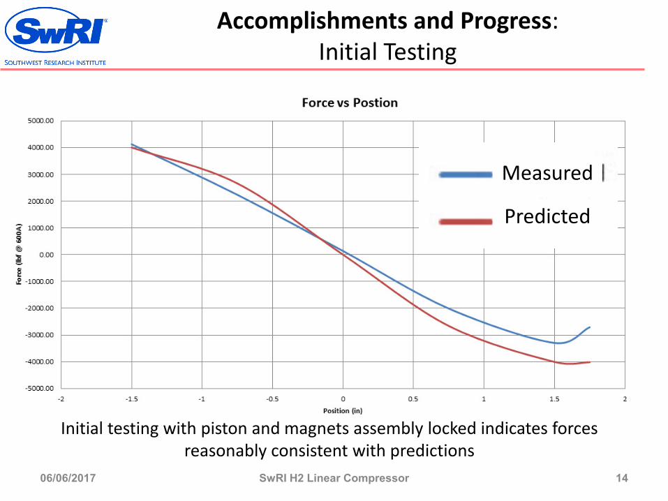
Accomplishments and Progress: Initial Testing
06/06/2017 SwRI H2 Linear Compressor 14
MagnetsSpacersInitial testing with piston and magnets assembly locked indicates forces
reasonably consistent with predictions
Measured
Predicted
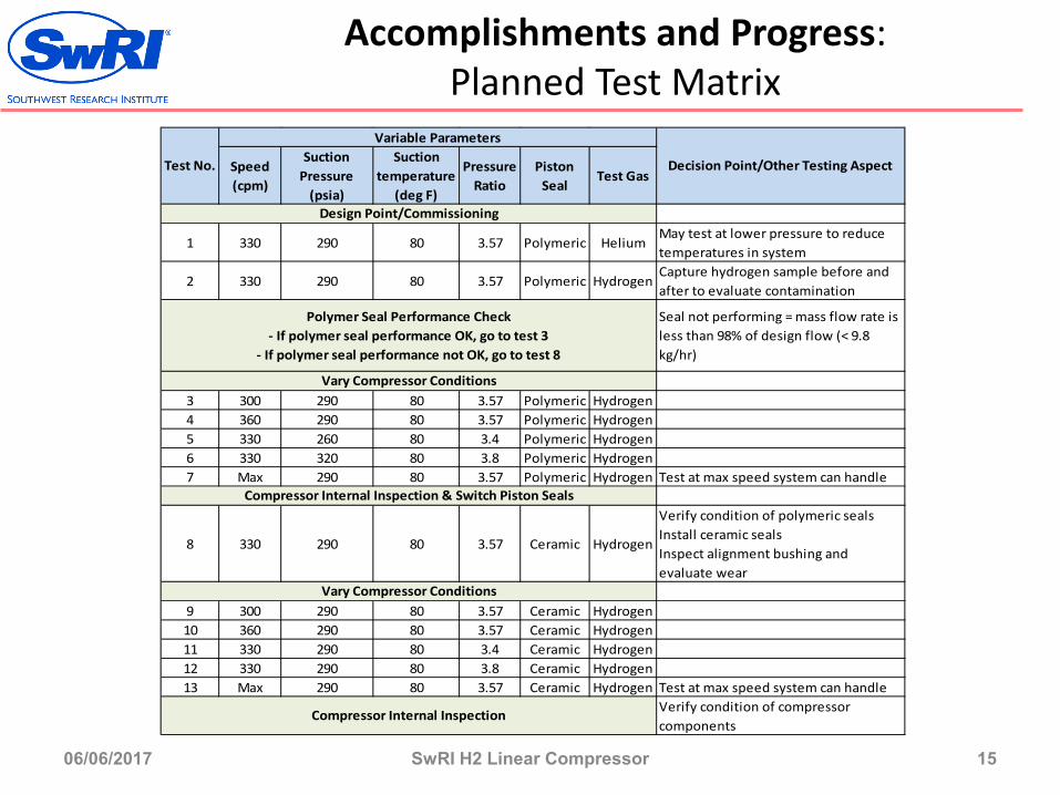
Accomplishments and Progress: Planned Test Matrix
06/06/2017 SwRI H2 Linear Compressor 15
Magnets
Coils
Spacers
Speed (cpm)
Suction Pressure
(psia)
Suction temperature
(deg F)
Pressure Ratio
Piston Seal
Test Gas
1 330 290 80 3.57 Polymeric HeliumMay test at lower pressure to reduce temperatures in system
2 330 290 80 3.57 Polymeric HydrogenCapture hydrogen sample before and after to evaluate contamination
Seal not performing = mass flow rate is less than 98% of design flow (< 9.8 kg/hr)
3 300 290 80 3.57 Polymeric Hydrogen4 360 290 80 3.57 Polymeric Hydrogen5 330 260 80 3.4 Polymeric Hydrogen6 330 320 80 3.8 Polymeric Hydrogen7 Max 290 80 3.57 Polymeric Hydrogen Test at max speed system can handle
8 330 290 80 3.57 Ceramic Hydrogen
Verify condition of polymeric sealsInstall ceramic sealsInspect alignment bushing and evaluate wear
9 300 290 80 3.57 Ceramic Hydrogen10 360 290 80 3.57 Ceramic Hydrogen11 330 290 80 3.4 Ceramic Hydrogen12 330 290 80 3.8 Ceramic Hydrogen13 Max 290 80 3.57 Ceramic Hydrogen Test at max speed system can handle
Verify condition of compressor components
Vary Compressor Conditions
Test No.
Design Point/Commissioning
Compressor Internal Inspection & Switch Piston Seals
Vary Compressor Conditions
Compressor Internal Inspection
Decision Point/Other Testing Aspect
Variable Parameters
Polymer Seal Performance Check- If polymer seal performance OK, go to test 3
- If polymer seal performance not OK, go to test 8

Accomplishments and Progress: Responses to Previous Year Reviewers’ Comments
• Concern that a 100 bar inlet restricts the usefulness of the LMRC in H2 applications –The LMRC is designed for a 20 bar inlet pressure. There was a reference to a 100 bar inlet pressure that was only used for a direct comparison of the LMRC design with the newer DOE target.
• Concerns about the overall efficiency of the compressor + driver –– The originally specified DOE goal for the project was isentropic efficiency, which is the efficiency of only the compression process. There was no mention of an overall system efficiency goal or requirement. Project focus has been on compression efficiency. The decision to mount coils externally reduced initial development risk, which reduces the efficiency of the driver in this initial prototype. Possible means to improve overall efficiency once proof of concept has been accomplished have been evaluated.
• Concerns that compressor footprint is too large –– The test loop layout is not ideal. It is laid out in a way that equipment is accessible for alterations during testing and to allow reuse of existing equipment. Previously shown layouts configure the equipment on space-efficient vertical panels that greatly reduce the footprint.
• The project needs input from a compressor manufacturer. –– For clarification, partner and co-funder, ACI Services designs custom compressors and compressor components, and supplies major components and systems to the industry as well as to the major compressor OEMs, and is highly-regarded in the gas compression industry.
06/06/2017 SwRI H2 Linear Compressor 16
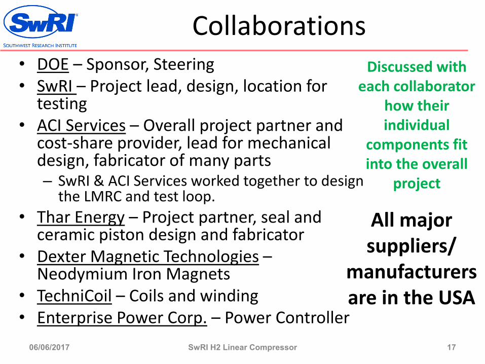
Collaborations• DOE – Sponsor, Steering• SwRI – Project lead, design, location for
testing• ACI Services – Overall project partner and
cost-share provider, lead for mechanical design, fabricator of many parts– SwRI & ACI Services worked together to design
the LMRC and test loop.• Thar Energy – Project partner, seal and
ceramic piston design and fabricator• Dexter Magnetic Technologies –
Neodymium Iron Magnets• TechniCoil – Coils and winding• Enterprise Power Corp. – Power Controller
06/06/2017 SwRI H2 Linear Compressor 17
All major suppliers/
manufacturers are in the USA
Discussed with each collaborator
how their individual
components fit into the overall
project
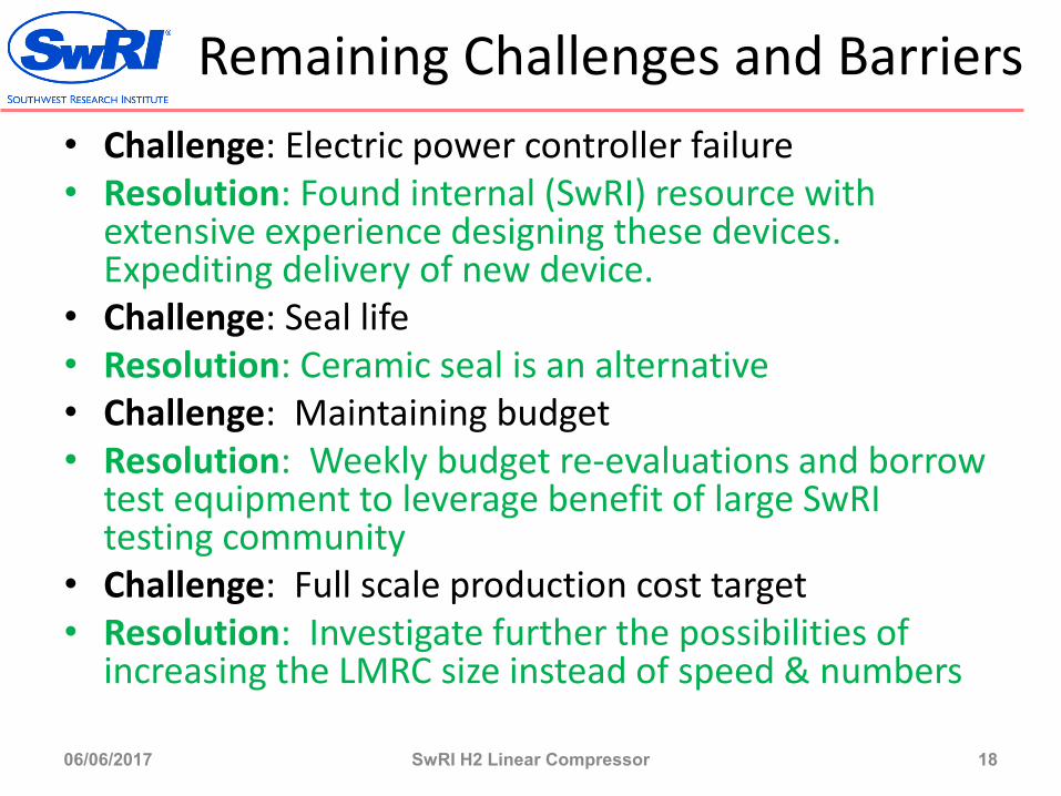
Remaining Challenges and Barriers• Challenge: Electric power controller failure• Resolution: Found internal (SwRI) resource with
extensive experience designing these devices. Expediting delivery of new device.
• Challenge: Seal life• Resolution: Ceramic seal is an alternative• Challenge: Maintaining budget• Resolution: Weekly budget re-evaluations and borrow
test equipment to leverage benefit of large SwRI testing community
• Challenge: Full scale production cost target • Resolution: Investigate further the possibilities of
increasing the LMRC size instead of speed & numbers
06/06/2017 SwRI H2 Linear Compressor 18
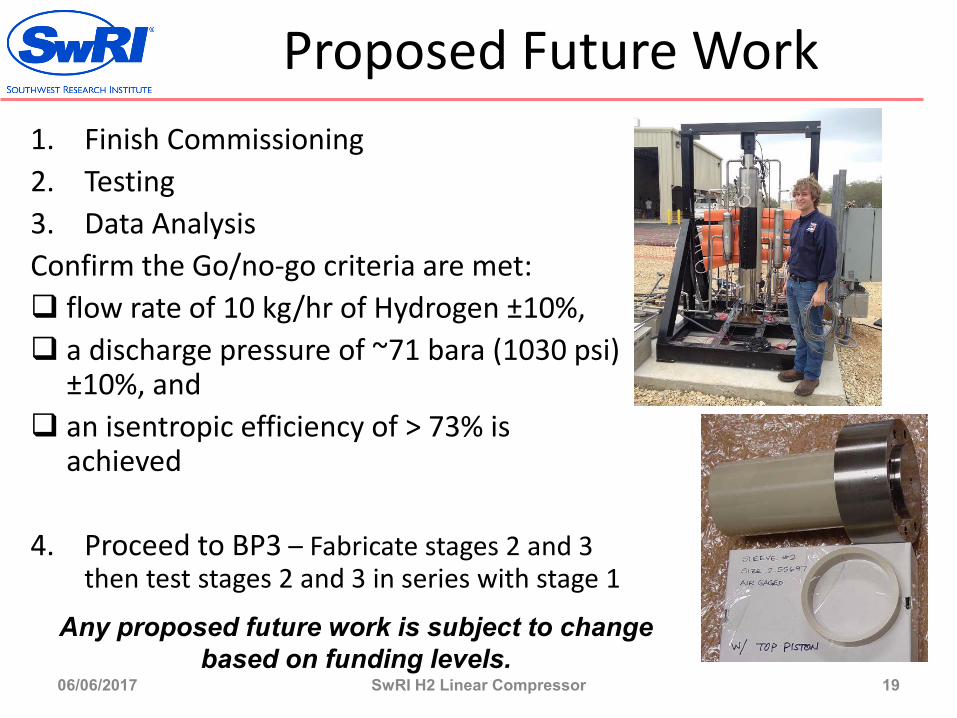
Proposed Future Work1. Finish Commissioning2. Testing3. Data AnalysisConfirm the Go/no-go criteria are met: flow rate of 10 kg/hr of Hydrogen ±10%, a discharge pressure of ~71 bara (1030 psi)
±10%, and an isentropic efficiency of > 73% is
achieved
4. Proceed to BP3 – Fabricate stages 2 and 3 then test stages 2 and 3 in series with stage 1
06/06/2017 SwRI H2 Linear Compressor 19
Any proposed future work is subject to change based on funding levels.
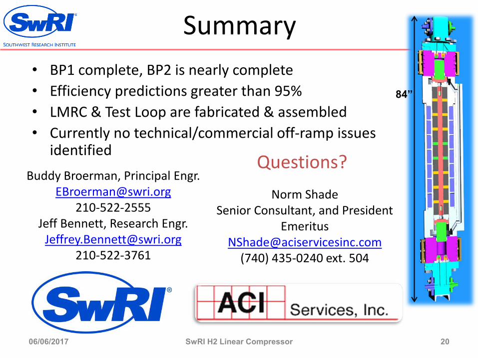
Summary• BP1 complete, BP2 is nearly complete• Efficiency predictions greater than 95%• LMRC & Test Loop are fabricated & assembled• Currently no technical/commercial off-ramp issues
identified
06/06/2017 SwRI H2 Linear Compressor 20
Buddy Broerman, Principal [email protected]
210-522-2555Jeff Bennett, Research Engr.
Norm ShadeSenior Consultant, and President
(740) 435-0240 ext. 504
84”
Questions?
Technical Back-Up Slides
21
Technical Backup Slide
06/06/2017 SwRI H2 Linear Compressor 22
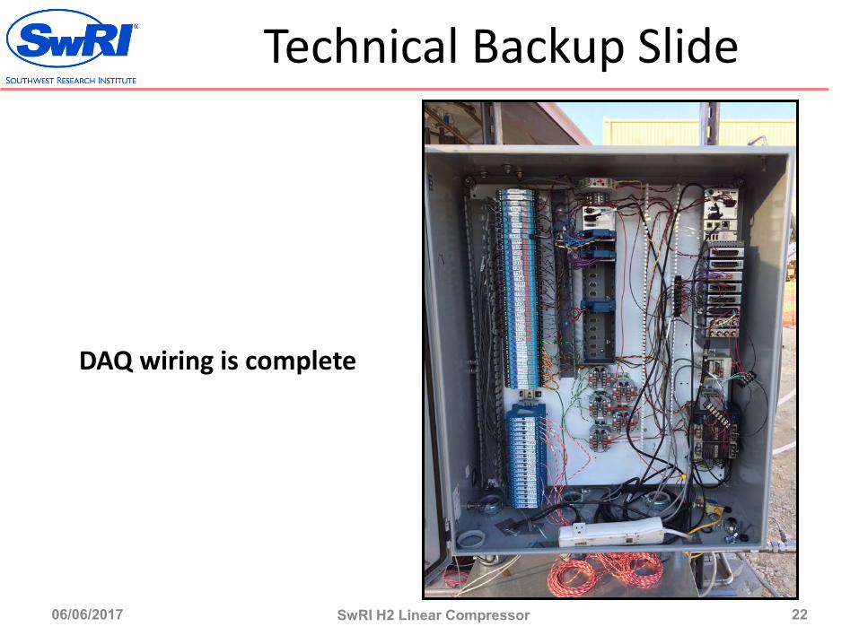
DAQ wiring is complete

Technical Backup Slide
06/06/2017 SwRI H2 Linear Compressor 23
Control panel for controlling LMRC motion and providing real-time feedback during operation
Technical Backup Slide
06/06/2017 SwRI H2 Linear Compressor 24
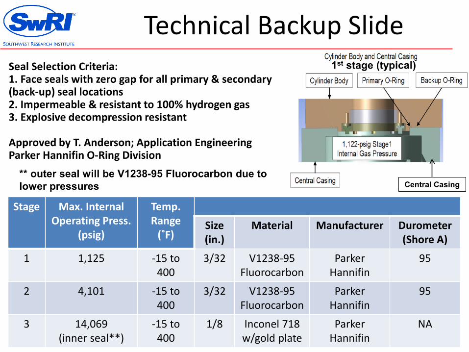
Stage Max. InternalOperating Press.
(psig)
Temp. Range(˚F)
Size (in.)
Material Manufacturer Durometer(Shore A)
1 1,125 -15 to 400
3/32 V1238-95Fluorocarbon
Parker Hannifin
95
2 4,101 -15 to 400
3/32 V1238-95Fluorocarbon
Parker Hannifin
95
3 14,069(inner seal**)
-15 to 400
1/8 Inconel 718 w/gold plate
Parker Hannifin
NA
Seal Selection Criteria:1. Face seals with zero gap for all primary & secondary (back-up) seal locations2. Impermeable & resistant to 100% hydrogen gas3. Explosive decompression resistant
Approved by T. Anderson; Application EngineeringParker Hannifin O-Ring Division
** outer seal will be V1238-95 Fluorocarbon due to lower pressures
1st stage (typical)
Central Casing

Technical Backup Slide
06/06/2017 SwRI H2 Linear Compressor 25
Materials selected for each of the compressor components, and the significant mechanical and physical properties for each