hydrogen infrastructure – asme rolefarajoosh-co.com/files/library/کلیات...
TRANSCRIPT

Welding

What is Welding?
– Welding is a joining process in which metals are heated, melted and mixed to produce a joint with properties similar to those of the materials being joined.
Welding
Penetration Depth
Weld Reinforcement
Heat Affected
Zone (HAZ)
Weld Pool Parent Metal
Weld Root

Pass Name:
– Root Pass
– Hot Pass
– Fill Pass
– Cover Pass (capping pass)
Welding

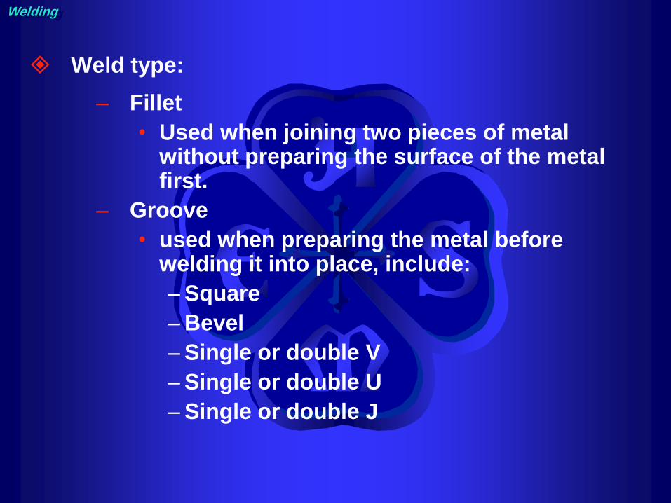
Weld type:
– Fillet
• Used when joining two pieces of metal without preparing the surface of the metal first.
– Groove
• used when preparing the metal before welding it into place, include:
– Square
– Bevel
– Single or double V
– Single or double U
– Single or double J
Welding

Fillet
– Approximately triangular
– Most common weld in structural work
Welding

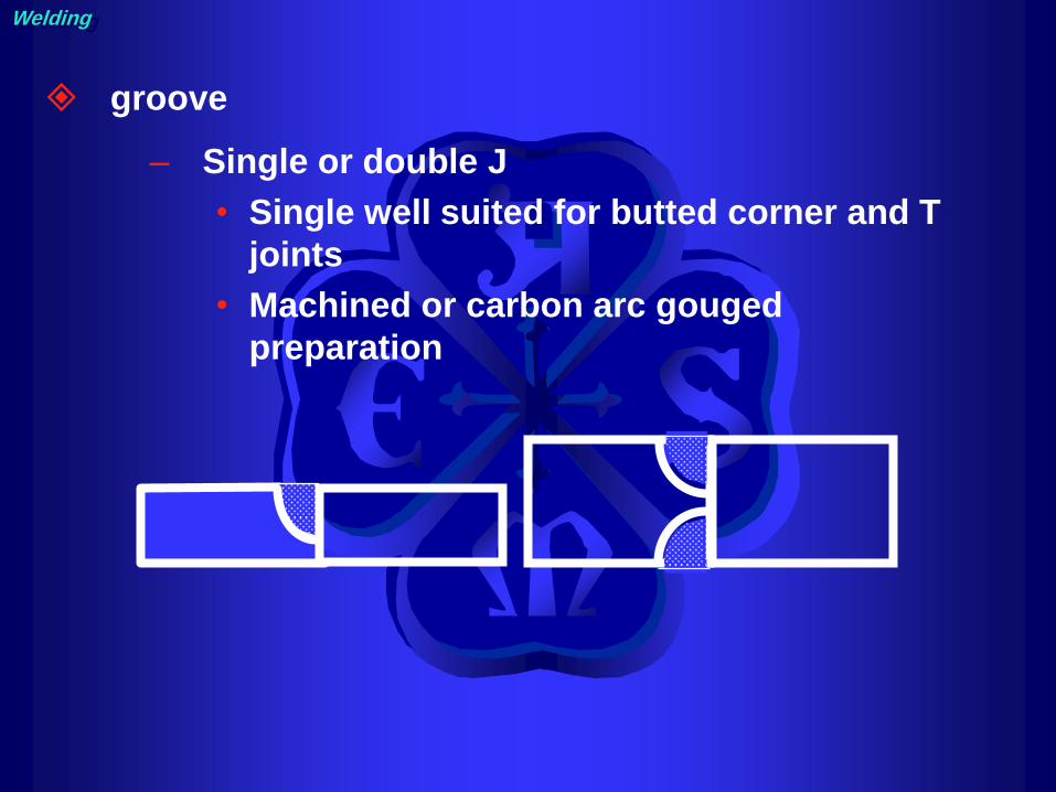
groove
– Square
• Penetration difficult with single; double
used to ensure strength
• Sometimes root is opened and a backing
bar is used
Welding

groove
– Bevel
• Single bevel is widely used
• Double preferred if metal thickness >3/4
Welding

groove
– Single V
• Both members beveled
• Butt joints for plate thickness greater than
1/4 inch
– Double V:
• welds reduce distortion
Welding

groove
– Single and double U:
• Rounded base allows larger electrodes
for narrower groove angles
• Machined or carbon arc gouged
preparation
Welding
groove
– Single or double J
• Single well suited for butted corner and T
joints
• Machined or carbon arc gouged
preparation
Welding

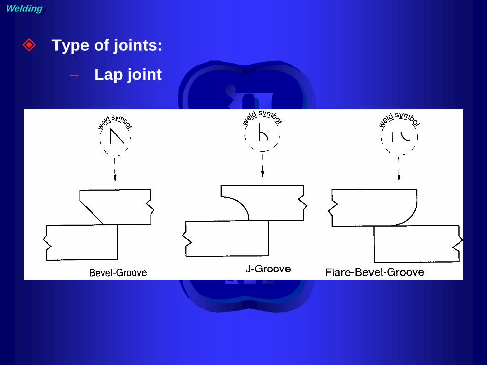
Type of joints:
– Butt joint
– T joint
– Lap joint
– Corner joint
– Edge joint
Welding

Type of joints:
– Butt joint
Welding

Type of joints:
– T joint
Welding
Type of joints:
– Lap joint
Welding

Type of joints:
– Corner joint
Welding

Type of joints:
_ Edge joint

Pipe welding position

Position:
– Flat
– Horizontal
– Vertical
– Overhead
Welding

Position according to standards:
– 1G
– 2G
– 5G
– 6G
– 1F
– 2F
– 2FR
– 4F
– 5F
Welding

Position:
– 1G for pipe
• Pipe rotated, Electrode is always at the top
• Either a split bead or weave technique may be
used
Welding

Position:
– 2G for pipe
• Pipe Axis Vertical, Weld is Horizontal, Pipe is
considered in a “fixed” position.
• Always use a split bead technique
• Always work from the bottom up.
Welding

Position:
– 5G for pipe
– Axis of the Pipe is Horizontal, The weld in vertical.
– Progression may be up or down.
– A weave bead is best used.
Welding

Position:
– 6G for pipe
• Pipe axis is fixed in position at a 45 degree
incline. The position includes flat, horizontal,
vertical, and overhead welds.
• A split bead technique is best used.
Welding
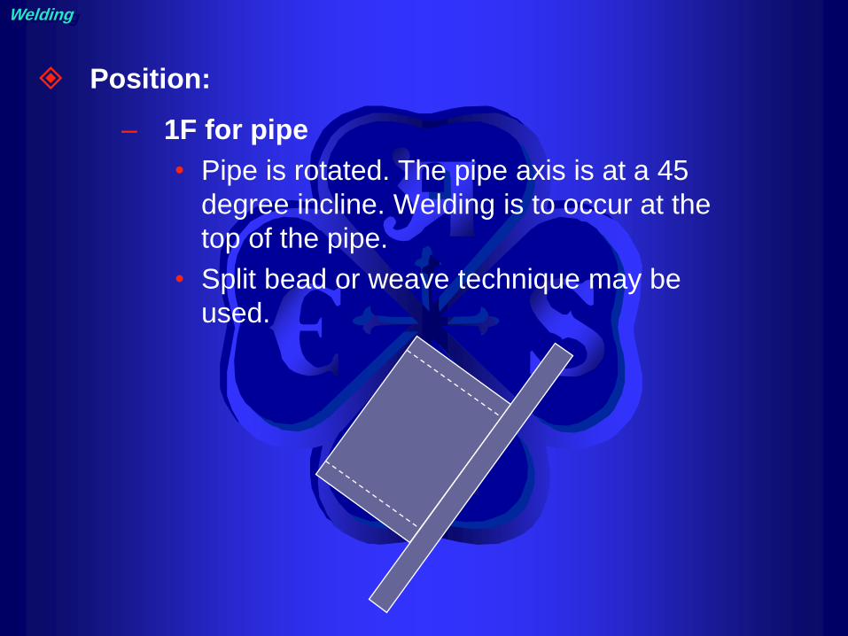
Position:
– 1F for pipe
• Pipe is rotated. The pipe axis is at a 45
degree incline. Welding is to occur at the
top of the pipe.
• Split bead or weave technique may be
used.
Welding

Position:
– 2F for pipe
• Fixed Position
• Best to use a split bead technique
Welding

Position:
– FR for pipe
– Rotated
– A split bead technique is best used.
Welding

Position:
– 4F for pipe
– A split bead technique is best used
Welding

Position:
– 5F for pipe
• Not Rotated. Progression may be up or
down.
• Split beads or weaves can be used on
5F-up welds, split beads are best used on
5F-down welds.
Welding

Welding Symbols

The welding symbols devised by the AWS
has 8 elements
– Reference line
– Arrow
– Basic weld symbols
– Dimensions and other data
– Supplementary symbols
– Finish symbols
– Tail
– Specification or others reference

Reference line and arrow pointing to the joint
the reference line has two sides:
– Other side, above the line
– Arrow side, below the side
ARROW SIDE
OTHER SIDE Arrow
ARROW SIDE
OTHER SIDE
ARROW SIDE
OTHER SIDE
ARROW SIDE
OTHER SIDE

Basic welding symbols

If a bevel groove is required the use broken arrow

Dimensions and other data

Dimensions and other data

Dimensions and other data
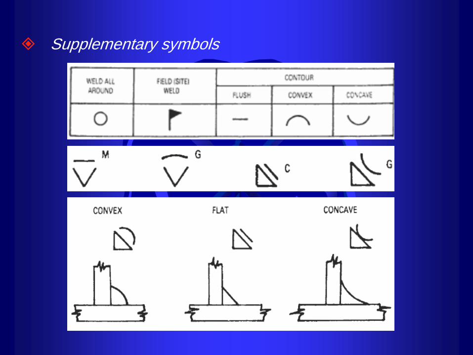
Supplementary symbols

A circle at the tangent of the arrow and the reference line means welding to be all around.

A flag at the tangent of the reference line and arrow means Field Weld.

Tail
The tail of the welding symbol is used to indicate the welding or cutting processes, as well as the welding specification, procedures, or the supplementary information to be used in making the weld .


Introduction to Welding Processes

Oxy-fuel gas welding
Welding
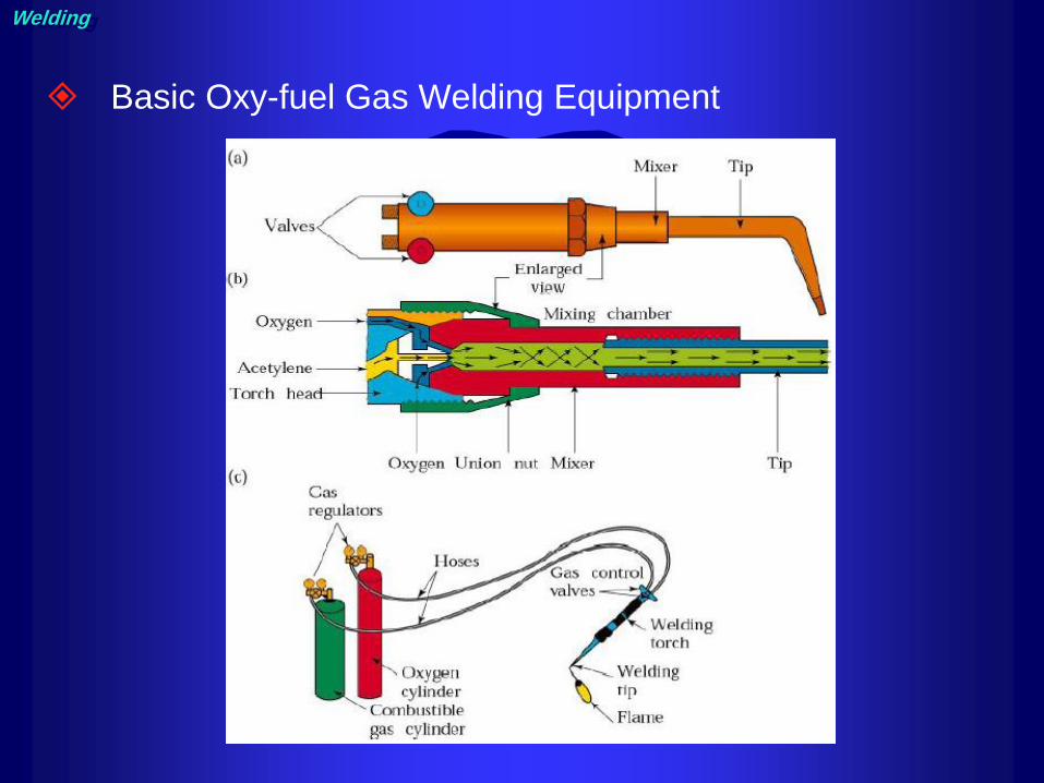
Basic Oxy-fuel Gas Welding Equipment
Welding

Pressure Regulators
Welding

Acetylene and oxygen cylinder
Welding

Carburizing, Neutral, and Oxidizing Flames
Welding

Advantages of Oxy-fuel Gas Welding
– Very portable
– Low cost
– Gentle flame
Disadvantages of Oxy-fuel Gas Weld.
– Poor air protection
– Low heat input
– Safety issues
Welding

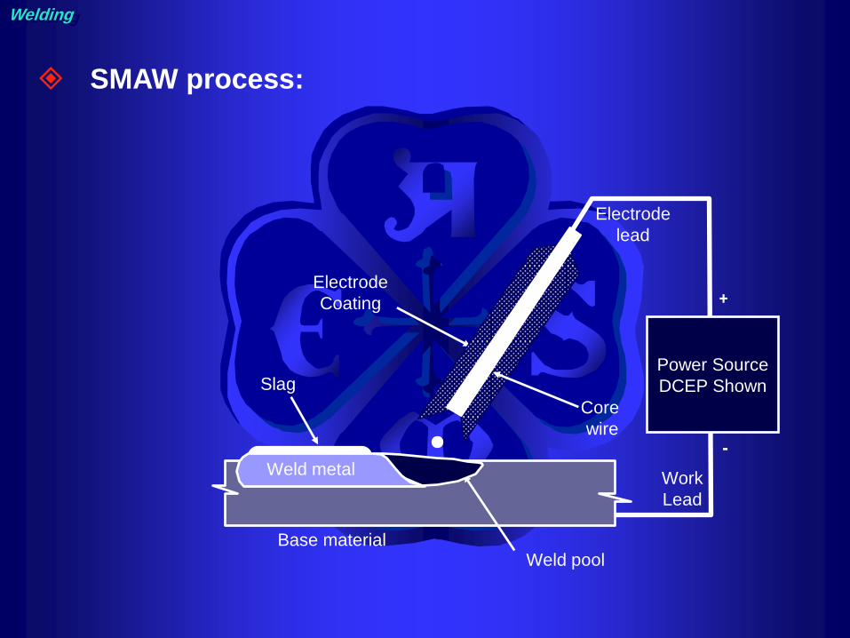
Shielded Metal-Arc Welding
( MMAW, SMAW, Stick welding)
Welding
Work
Lead
+
-
Electrode
lead
Power Source
DCEP Shown
Base material
Electrode
Coating
Core
wire
Weld pool
Slag
Weld metal
Welding
SMAW process:

Welding
electrode

E xx y z – n HmR
positions (y) 1=all positions
2=flat + horizontal
4=vertical down
Tensile strength
41 = 410 MPa min
48 = 480 MPa min
Flux type (z) 0, 1 = cellulosic
2, 3, 4 = rutile
5, 6, 8 = low hydrogen
7 = iron powder + iron oxide
Impact properties (n) 0 = 47J at 0°C
2 = 47J at -20°C
3 = 47J at -30°C
4 = 47J at -40°C
Hydrogen level (HmR) H5 = 5 ml / 100g of WM
R = low moisture
Welding
Electrode numbering:

Advantages
– Equipment simple, inexpensive, and
portable
– Process can be used in any position
– Shop repairs, pipelines, building
construction
Disadvantages
– Limited deposition rate relative to other
welding processes due to stubs and slag
– Weld not well protected form the
atmosphere
– Welds have more inclusions than welds
made with other processes
Welding

SMAW usually restricted to metals between 3 to
19mm (1/8 to 3/4 in) thick.
Typical pass 3mm (1/8 in) thick.
Welding
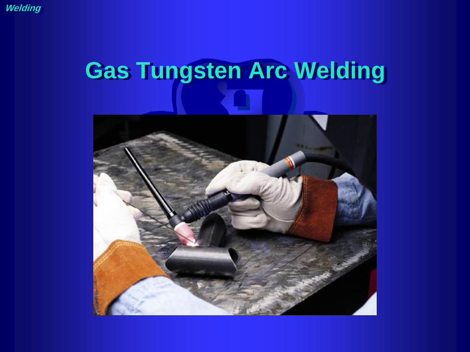
Gas Tungsten Arc Welding
Welding
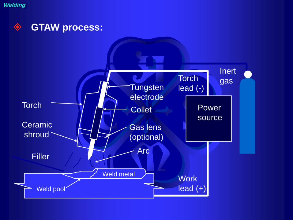
Ceramic
shroud
Torch
Gas lens
(optional)
Inert
gas
Power
source
Torch
lead (-)
Work
lead (+)
Filler Arc
Weld metal
Weld pool
Collet
Tungsten
electrode
Welding
GTAW process:
Welding
TIG Process features :
– can also be used to weld dissimilar metals
(but not very well)
– Slower and more costly than consumable
welding
– Independently added filler
– Used for root, pass runs in pipe or thin
sheet
– High quality, Clean process, no slag
– Low oxygen and nitrogen weld metal
– Defect free, excellent profile even for single
sided welds

TIG

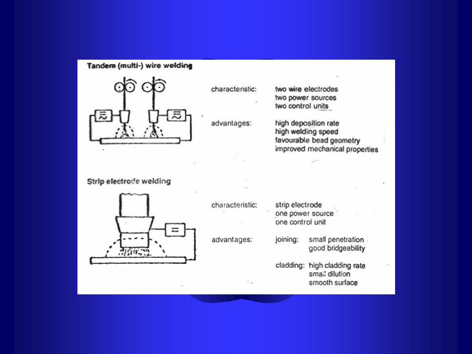
Submerged Arc Welding

Sub-merged Arc Welding


Metal Inert / Active Gas Welding


Welding

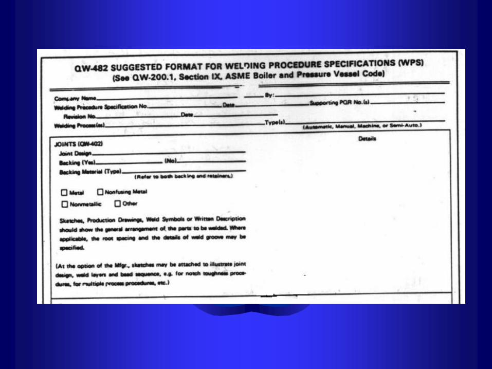
WPS & PQR


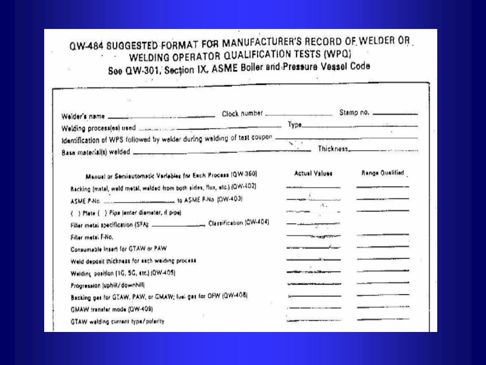


API 1104

AWS-D1.1

SLV

WOQR

WOQR-SLV

Welding Defects

Welding Inspection parameters:
– WPS, PQR shall be approved
– Welder shall be qualified according to ASME SEC. IX
– All welding processes shall be protected from adverse
weather (use shelter)
– All welding equipment shall be calibrated
– When preheat is applied, welding shall not be interrupted
or stopped until 30% of the final weld has been completed
– Bolts hole:
• symmetrically from a vertical center line
• Symmetrically from plant north


Porosity

Lamination

Lamellar Tearing

Misalignment

Dimensional
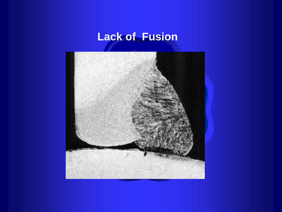
Lack of Fusion

Slag Inclusion

Under fill

Undercut /Overlap

Cracks

Convexity

Incomplete Penetration
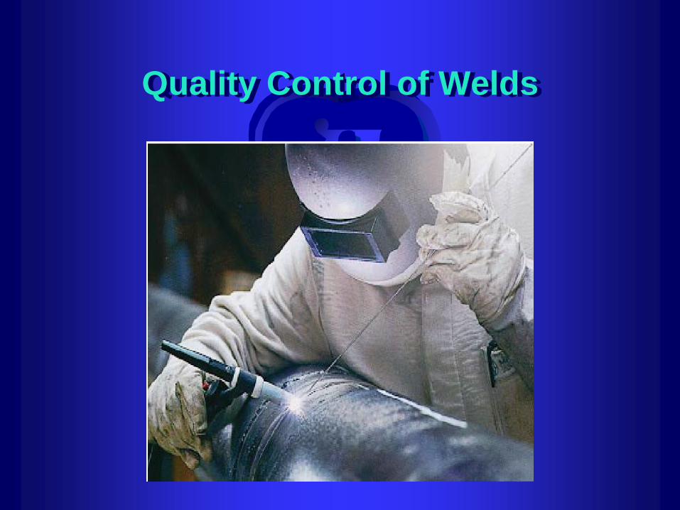
Quality Control of Welds

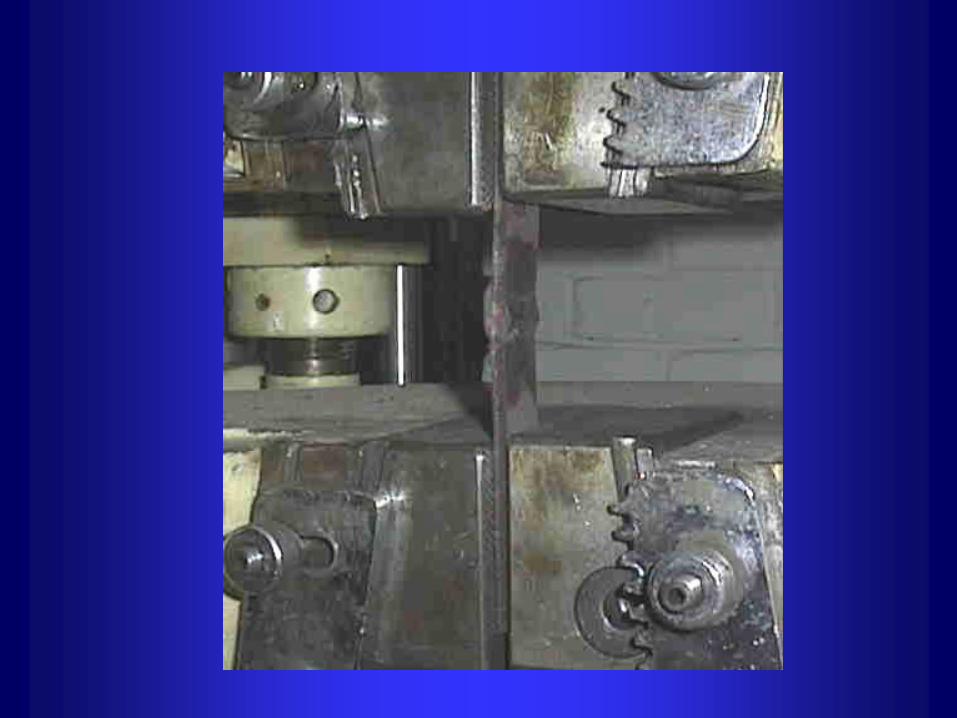
Weld Destructive Test include:
– Tensile
– Bending
– Impacting
– Hardness

Material is sectioned and edges rounded of to
prevent cracking. Punch marks are made to see
elongation.

Shows physical condition of the weld and
Determine welds efficiency
– Tensile strength
– Ductility
– Fusion and penetration

Bend through 180O
the specimen should be a minimum of 30mm wide
The fulcrums diameter is 3x thickness of the plate
The bottom rollers have a distance of the diameter
of the former + 2.2 times the thickness of the plate
Upper and lower surfaces ground or filed flat and
edges rounded off.
the tests should be one against the root -another
against the face ,and in some cases a side bend.


CHARPY AND IZOD:
– Gives the toughness and shock loading of
the material and weld at varying
temperatures with a notch such as under cut
– The measurement is the energy required to
break a specimen with a given notch
– 2mm depth at a 45obevel or a “U” notch.


This gives the metals ability to show resistance
to indentation which show it’s resistance to
wear and abrasion.
Weld Non-Destructive Test include:
– Penetrate inspection
– Magnetic particle inspection
– Ultrasonic inspection
– Radiographic inspection
– Eddy current inspection
– Visual inspection

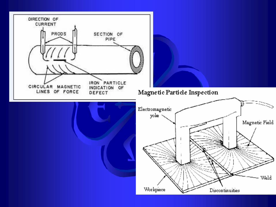
Magnetic Particle Inspection (MT)
Magnetic particle inspection is a method of locating and defining discontinuities in magnetic materials It is excellent for detecting surface defects in welds, including discontinuities that are too small to be seen with the naked eye, and those that are slightly subsurface. This method may be used to inspect plate edges prior to welding, in process inspection of each weld pass or layer, postweld evaluation and to inspect repairs
Liquid Penetrant Inspection (PT)
Surface cracks and pinholes that are not
visible to the naked eye can be located
by liquid penetrant inspection. It is
widely used to locate leaks in welds and
can be applied with austenitic steels and
nonferrous materials where magnetic
particle inspection would be useless.


Radiographic Inspection (RT)
Radiography is based on the ability of X-rays and gamma rays to pass through metal and other materials opaque to ordinary light, and produce photographic records of the transmitted radiant energy. All materials will absorb known amounts of this radiant energy and, therefore, X-rays and gamma rays can be used to show discontinuities and inclusions within the opaque material. The permanent film record of the internal conditions will show the basic information by which weld soundness can be determined.


Ultrasonic Inspection (UT)
Ultrasonic Inspection is a method of
detecting discontinuities by directing a
high-frequency sound beam through the
base plate and weld on a predictable
path. When the sound beam's path
strikes an interruption in the material
continuity, some of the sound is
reflected back. The sound is collected by
the instrument, amplified and displayed
as a vertical trace on a video screen


Acoustic emission
Acoustic Emission is the class of phenomena whereby an elastic wave, in the range of ultrasound usually between 20 KHz and 1 MHz, is generated by the rapid release of energy from the source within a material. The elastic wave propagates through the solid to the surface, where it can be recorded by one or more sensors. The sensor is a transducer that converts the mechanical wave into an electrical signal. In this way information about the existence and location of possible sources is obtained. The basis for quantitative methods is a localization technique to extract the source coordinates of the AE events as accurately as possible.

Visual Inspection (VT)
Visual inspection is often the most cost-effective
method, but it must take place prior to, during
and after welding. Many standards require its
use before other methods, because there is no
point in submitting an obviously bad weld to
sophisticated inspection techniques. Visual
inspection requires little equipment. Aside from
good eyesight and sufficient light, all it takes is
a pocket rule, a weld size gauge, a magnifying
glass, and possibly a straight edge and square
for checking straightness, alignment and
perpendicularity.

Thanks for Your Attention