hydrogen ventilation test facility for underground mining
TRANSCRIPT

1
HYDROGEN VENTILATION TEST FACILITY FOR UNDERGROUND
MINING AND TUNNELING
Human, G.*,1, Oelofse, F.*,2, Bessarabov, D.*,3 and Le Roux. N.*,4
*Hydrogen South Africa Infrastructure Centre of Competence, Faculty of Engineering, North-
West University, 11 Hoffman Street, Potchefstroom, 2531, South Africa,
emails: [email protected], [email protected], [email protected], [email protected]
ABSTRACT
One of the focus areas in the heavy-duty transport industry globally is de-carbonization of trucks, dozers,
shovels, semi-trucks, buses, etc. Hydrogen fuel cells (FCs) technology is one considered solution for the
industry due to its zero-emissions, its MW scalability and capacity to store large amounts of energy for
long duration continuous power operation. Underground deep mines is another option for deployment
and operation of hydrogen FCs. Benefits include lower emissions, improved health, comfort and safety,
as well as reduced operating costs. Underground mining trucks, loaders and other machines have power
ratings up to 750 kW, which proves difficult for battery and tethered electric energy. Hydrogen FCs
have the ability to overcome these power and energy storage limitations. The risks and technologies
associated with delivering, storing and using hydrogen underground first need to be investigated and
proven safe. This work presents the design, construction and operation of a mining ventilation test
facility (VTF) at the North-West University in South Africa that aims to quantify the risk of hydrogen
in confined ventilated environments. Initial work has been conducted on measuring concentrations of
hydrogen released in the temporary ventilation site and is discussed.
Keywords: hydrogen fuel cell, hydrogen safety, underground mining, HySA, ventilation
1.0 INTRODUCTION
Mining companies are facing significant challenges in their efforts to de-carbonize and not loose on
productivity and cost. 2015 data showed that half of worldwide industrial greenhouse gas emissions
could be traced back to just 50 companies [3]. Two mining companies were in the top 5, and 20 of the
top 100. Conventional powering technologies like diesel and batteries are not simultaneously clean, safe,
and productive. Tethered vehicles are power-dense and have no direct emissions. However, the tether
introduces additional safety fears, interferes with mobility and productivity, and introduces weaknesses
and high strain at the tether interfaces [1]. Diesel internal combustion engine(ICE)-powered equipment
are power-dense but more mobile and more productive than tethered, but generate harmful emissions
and unwanted heat due to inefficiencies along with wasted heat from torque converters that require
expensive additional ventilation and cooling [1]. Because workers are constrained to an underground
workplace, mining is one of the most regulated industries. Implementing more strict emissions and noise
regulations will further increase vehicle capital and operating costs and lower mine productivity.
Changing to electrical drive trains provide significant benefits in the mining environment. A sensitivity
analysis of diesel-, battery- and tethered-powered equipment shows that the capital cost benefits are not
considerable: battery equipment is 5% more expensive and tethered 2.5% less expensive than the diesel
equivalent. Tethered and battery equipment showed a 29.5% lower maintenance cost than diesel. Battery
equipment added 6% battery replacement cost but 5.5% more annual tonnage than diesel while tethered
resulted in a sizeable 27% less tonnage. Cost differences are more sensitive to electricity prices than to
diesel fuel fluctuations [2]. According to cost trends from the energy information agency (EIA), diesel
prices will increase significantly while intermittent renewable energy (RE) sources like solar and wind
will decrease in price [2]. The drawback of these RE sources is their intermittent nature, requiring short-
term to seasonal storage capabilities to support grid stability as well as supply energy when these sources
are not abundant due to seasonal changes. Hydrogen has been researched in many industries as an energy
storage technology for intermittent sources and is seen as a solution to prevent curtailment of RE, to
store this energy and use later when needed. The added benefit for mines, especially remote ones, is the
ability to produce their own hydrogen for FC powered equipment. Both RE and electrolysis technologies

2
have experienced capital and operating cost reduction [2], and provides a solution for mines to transition
to complete energy independence. The Government of Chile proposed a center for energy transition of
mining industries by the adoption of new technologies. Proposed research topics include solar PV and
concentrated solar technologies, storage technologies, hydrogen and liquid fuel technologies that can
serve the transport and processing activities of the mining sector [5].
Hydrogen powered equipment and their cost benefits have been studied in the past. Bétournay et al. [4]
conducted FC vs. diesel cost-benefit analysis for Canadian mines. At the time FC-powered machines,
based on expensive metal-hydride technology, showed a cost reduction in both operation and
maintenance of equipment as well as overall mine ventilation and cooling requirements. Cost of
hydrogen and diesel used in the analysis were estimated at $3.85/kg (~$0.12/kWh) and $0.5/liter
(~0.05/kWh) respectively. Efficiency curves of typical PEM FC and diesel ICE given in Fig. 1a, show
the FC to be more efficient that the diesel ICE through the entire power range. Fig. 1b provides the
usable energy cost comparison between diesel fuel at a 5 year projected price of $1.43/liter and hydrogen
fuel at $3.00/kg possible with large-scale RE hydrogen production. Cost of electricity is again identified
as the dominant cost factor for load-factors above 50% [6]. For typical mines there exists a potential for
24 to 53% reduction in the electrical operating cost of the primary ventilation system for an intake
airflow reductions of 9% for operations below 2400 m depth, and intake airflow reductions of 24% for
operations between 400 – 800 m depth. Reduction in auxiliary ventilation system operating costs are
between 11 and 20%. Reductions in greenhouse gas emissions for the same sites results in 27 to 38%
by replacing diesel ICEs with FCs [7].
Figure 1a. Diesel ICE vs. FC efficiency. Figure 1b. Diesel vs. hydrogen energy cost.
Although hydrogen FC powered equipment could provide health, comfort and economic benefits,
hydrogen safety in underground confined spaces is a major concern. Various components and systems
are usually required to measure, alarm, and mitigate when unsafe scenarios arise. Hydrogen in
underground confined spaces is however not understood. Several issues have been identified regarding
hydrogen in underground mining [7]. One issues is the amount of ventilation required to dilute a possible
hydrogen leak that could result from the hydrogen system on-board the FC powered equipment. There
are also no codes and standards for hydrogen FC powered equipment underground.
This work describes the development of a hydrogen VTF with the purpose of addressing these issues by
evaluating and quantifying the risks associated with the use of hydrogen in ventilated underground
mining and tunneling environments. The next section provides background on FCs in mining and gives
a history of work done in the past. Next is a section providing design detail of the temporary and main
VTF and safety considerations, including specification and safety. Initial results and discussions are also
provided. This is followed by a discussion of future work and a conclusion.
2.0 BACKGROUND
The first mention of hydrogen FC application in underground mining dates back 20 years [8]. At the
time hydrogen FCs were determined to be economically viable for underground mining. Providing
traction power in enclosed highly regulated environments is a challenge and the inadequacies of
3
conventional power are the basis of economic stress in the industries. Clean, safe, and productive FC
powered equipment offer cost offsets that are commercially successful. Despite the high capital cost of
FCs, cost offsets arising from solving problems associated with enclosed, underground operating
environment (emissions, noise, heat, etc.) make FC more cost-competitive than in surface applications.
These offsets allow the FC powered equipment to compete strictly on economic merit. The reason FCs
have not been more actively pursued for the underground environment, is possibly from the
misperception and misrepresentation of safety associated with hydrogen gas, especially with the
advanced materials available today. Reference is always made to hydrogen’s wide flammability limits
and ignition energy. The fact that acetylene cylinders, commonly found in household garages, in every
workshop around the world and even in underground mines, posing similar and in many cases more
undesirable properties than hydrogen, is unnoticed most probably due to it being a commonly used gas.
Hydrogen has an ignition temperature almost double that of acetylene, diesel and gasoline, and higher
than Methane. Hydrogen has a low ignition energy but in fact is equal to that of acetylene. Moreover,
acetylene has a wider flammability range than hydrogen, and acetylene unlike hydrogen can violently
decompose and explode without oxygen, a spark or flame present. Hydrogen has a very low buoyancy
and high diffusion coefficient; properties that allow designing safety concepts to get rid of hydrogen
effortless. Although hydrogen has these attributes, it is the smallest molecule and therefore could leak
much easier.
In September 1999 a consortium of companies lead by the Fuelcell Propulsion Institute (FPI) [9]
received funding to develop a FC powered mine locomotive using metal-hydride storage [10].
Underground testing occurred in October 2002 in a gold mine under representative production mine
conditions. The locomotive performed flawlessly with zero failures or downtime. The FC-locomotive
showed 100% power availability for 8½ hours operation, whereas the battery-powered version revealed
a steady performance decrease for around 7 hours of operation. A second project was to develop a FC-
hybrid powered mine loader. The project had three goals: develop a FC powered mine loader, develop
associated MH storage and refueling systems and demonstrate the FC hybrid loader underground [11].
The working loader was developed and successfully tested aboveground. Following these two successful
projects, examining the direct application to underground vehicles, called the Hydrogen Mine
Introduction Initiative (HMII), was implemented [15, 16]. The HMII main objective was to develop
norms and standards to support mining regulations for technological application in underground
vehicles. The HMII was an industry consortium established to develop and test a range of needed
operational technology, specifications and best practices for hydrogen power applications in
underground mining vehicles in order to consider this technology as replacement to diesel. Two later
projects by FPI and funded by Anglo American Platinum Ltd. (AAPL) included a second locomotive
and a FC-powered mining dozer [12]. Like all previous demonstrators, both used hydrogen reversible
metal-hydride hydrogen storage. AAPL continued the dozer demonstrations, and have recently
demonstrated the same dozer using liquid organic hydrogen carrier (LOHC) technology and plans to
start testing underground in 2019 [13].
Even with FC power-plant capital costs much higher than comparable diesel power-plants, FCs are still
cost-competitive due to other important cost components (recurring costs) besides capital cost that were
lower for the FC. Recurring costs considered included fuel, tires, driver and maintenance labor, labor to
assure conformance to diesel regulations, e.g., exhaust- gas sampling lost time, consumable parts such
as filters, drivetrain maintenance due to breakdown and rebuild, and engine control system (safety
system) breakdown and rebuild costs. This is for values conservative towards diesel, assuming that both
recurring and capital costs would remain constant over time. Both these cost components would in-fact
increase. A FC production vehicle would be more productive than a diesel vehicle for a number of
reasons: higher allowed vehicle density, higher availability, substantially higher performance, and lower
non-vehicle subsidiary mine operating costs such as ventilation [1]. From literature reviewed, the
immediate issues, resulting in the opportunities identified to necessitate the need for an alternative such
as hydrogen FCs underground, is summed up:
De-carbonization of the underground mining industry: Removing diesel emissions and CO2.
Health and comfort: FCs offer noise and vehicle heat load reduction.

4
Operating Costs: Includes ventilation costs savings in energy bills. Further cost savings related
to diesel equipment, maintenance, downtime (improved production), automation and reliability.
More recently, several publications and reports mention hydrogen as a solution for the mining industry.
A recent publication by the Rocky Mountain Institute (RMI) mentions the rise of current FC powered
vehicles and highlights the similarity in power requirements of a typical mining truck and Alstom’s
Coradia iLint train and the Nikola One truck [17]. By 2020 hydrogen could already be competitive with
US gasoline prices. Hydrogen has other advantages besides cost, which include electrolysis plants to
prevent intermittent RE curtailment and grid stability assistance. The Columbia Centre on Sustainable
Investment recently published in a report that hydrogen is particularly attractive to the mining sector, as
it can provide a storage solution for distributed RE and fuel for trucks and power generation systems
[18]. The consequence would be a reduction in logistical and operational costs and give mine operators
system redundancy and backup fuel stock, as well as reduction in ventilation requirement and cost.
Energy and Mines published an article titled “Hydrogen in mines: the missing piece of the puzzle” [19].
Ten years ago, hydrogen FC focus was on passenger cars. The focus has now shifted to large, heavy-
duty vehicles. Heavy vehicles and heavy cycle vehicles require the power density possible with
hydrogen. A demonstration at Glencore’s Raglan mine in the North of Quebec, utilizes hydrogen in a
hybrid system to generate electricity for mining operations. The was commissioned in December 2015.
The system consists of a wind turbine, electrolyser and FC with hydrogen tanks, as well as flywheel and
battery storage. The storage systems reduced the need for wind curtailment and additionally reduced the
need for diesel power and spinning reserves in total [20]. In 2018 CORFO, the Chilean economic
development agency awarded two projects specific to the mining industry [21]. The first is for a dual
fueled (diesel and hydrogen) mining truck. The project is to convert a surface mining extraction truck
and demonstrate the technical and economic viability of running the machine on a duel-fuel; hydrogen
and diesel. Recent works on this topic have published promising results [21]. Surface mining extraction
trucks that are targeted have power plants ranging from 225 kW to 3 300 kW with payloads between 20
and 500 tons. The second project will focus on FC power for loaders. Underground loaders have typical
power plants ranging from 110 kW to 375 kW with payloads between 7 and 20 tons.
Issues identified include hydrogen re-fueling infrastructure and protocols, as well as the costs of metal-
hydride storage units [10]. Since the last demonstration projects, hydrogen storage technologies and
infrastructure have seen considerable development that results in much lower costs than metal-hydride
beds. Further, no safety regulations exist relating to FC and hydrogen in mining applications [11]. Cost
of FC stacks is listed as a barrier, but these costs have come down considerably. FC system cost
projections for 2020 is below $100/kW for FC based on annual production rates of 100,000 systems/year
for medium delivery vehicles having power requirements in the 160kW range. Costs for heavy-duty
vehicles could be double due to lower production numbers [22]. Additional issues related operational
and safety included:
Little information on the behavior of hydrogen (release, turbulence) in enclosed spaces and none
for mining, with and without ventilation and behavior versus lower flammability levels.
Design, performance, reliability of available on-board hydrogen storage: safety assessment,
hazard analysis.
Existing Mine Regulations, Hydrogen Codes and Standards
o No mine regulations (coal, metal) against hydrogen.
o Hydrogen infrastructure already established for surface vehicles.
o International hydrogen installation codes and standards can support mine regulations.
o Comply with prevailing generic standards and codes elsewhere.
o All hazards should be demonstrated to be “as safe, or safer than”.
o Address mine-specific aspects: planning, ventilation, emergency response, fire
suppression, etc.
o Include special provisions for transportation of hydrogen.
Lack of dedicated refueling infrastructure.
Lack of performance and durability data (vehicles, hydrogen infrastructure).

5
All the issues identified, as well as safety perceptions, have prevented the implementation of hydrogen
FC technologies in mining activities, especially underground. To make hydrogen possible in the
underground mining environment, the issues identified require research, development and
demonstration to fast track the technology to implementation.
3.0 VENTILATION TESTS FACILITY
The limitations as well as numerous benefits mentioned, have motivated the need to develop a research
infrastructure platform dedicated to hydrogen safety device testing and validation and qualification of
underground risks using hydrogen based fuels in both ventilated and unventilated confined underground
mining spaces and due to the nature of the problem, tunneling activities will also benefit.
3.1 Project background
A deliverable of the HMII project was to field-test hydrogen leak behavior in ventilated and confined
areas [15, 16]. The project included performing leak tests inside a 20” container and included several
hydrogen release and ventilation flow configurations and conditions. Hydrogen leaks considered were
typical that would be expected from a metal-hydride bed at low pressure (>20 bar). A similar project
was initiated by the Hydrogen South Africa Infrastructure Centre of competence (HySA) at the North-
West University in South Africa. The objective was to perform similar tests starting at low pressure and
then move to pressures as high as 350 bar, typical pressures of composite on-board tanks. General safety
concerns of high-pressure hydrogen in confined spaces was not justified or supported by any results and
will be answered by performing tests at these conditions.
Initial tests were performed at the Council for Scientific and Industrial Research (CSIR) Kloppersbos
explosion test facility near Pretoria, South Africa. The CSIR typically uses this facility to perform full-
scale simulations of underground ventilation systems. The facility represents a full-scale underground
coalmine section arranged in a last through road, heading and pillar split configuration. HySA used this
facility to perform initial hydrogen release experiments. Hydrogen is released through an orifice to
simulate a leak and hydrogen concentration is measure at different locations and ventilation airflow
values. A PEM electrolysis unit was transported to the site for onsite hydrogen generation. Logistics of
having hydrogen onsite and not knowing how much hydrogen would be required necessitated the need
to have onsite generation. Future activities would have included the delivery of high-pressure hydrogen
cylinder packs to the site once the experimental setup and characteristics were understood. The
maximum pressure available from the hydrogen generation unit was 14 bar. This was sufficient for
initial concept validation experiments. The strategy was to determine how and if hydrogen can be
measured in the environment. Hydrogen was “leaked” into the tunnel in the direction of ventilation
airflow at a fixed height, with hydrogen detectors lined up in front at the release level and one more
level above the release level. Two ventilation fans are located at the opposite side of the tunnel. Fig. 6
(a) shows a sensor configuration and the direction of airflow. Fig. 6 (b) shows an experimental setup.
Figure 6 (a). Kloppersbos experimental tunnel
and layout.
Figure 6 (b). Sensor configuration inside
Kloppersbos tunnel.
Hose and release point
Sensors
Airflow direction

6
Although these initial experiments provide insight into the propagation of hydrogen, their purpose was
to prove the concept. Future experimental work will require varying release rates, pressures, direction
and orientation in the ventilation flow, and changing the ventilation airflow itself from no-flow up. The
Kloppersbos facility however presented some challenges, which included:
high daily charges for using the facility with several days required for setting,
the facility was 150 km from HySA’s offices. Both transporting hydrogen from the HySA site
or having hydrogen delivered was also very costly and time consuming,
the tunnel had a fixed configuration and it would be expensive to make alterations,
the ventilation tunnel was for a specific underground coalmine section arrangement which
would not represent deep metal mines,
the existing ventilation fan was old and the airflow control was manual and difficult to tune, and
the existing ventilation fan maximum airflow rate was low (1.0 m/s max cross-section average),
and higher air-flow rates were desired.
Fixing and retrofitting the facility and operating costs for rent, supply of hydrogen and time lost for
hydrogen delivery, traveling and accommodation costs was expected to be very high. Exhaustive
experimental tests would take several years. Based on these considerations, a decision was made to
develop a dedicated VTF with features of deep metal mining and to include on-site production and
storage. Additional benefits of such a facility is demonstrating a remote self-sufficient mining site.
3.2 Temporary ventilation test site
The development of a full-scale VTF would require time to identify a location, equipment, complete a
design and perform necessary environmental assessments. Validating and testing sensors and concept
was performed in parallel at a temporary site consisting of a 40”container, shown in Fig. 7 (a). Hydrogen
was supplied from HySA’s current production site and supplied to the temporary ventilation site in
cylinder packs (200 bar 12 x 50 L). A typical sensor layout used is shown in Fig. 7 (b).
Figure 7 (a). Temporary ventilation test facility. Figure 7 (b). Sensor layout.
A custom designed low-pressure, high flow ventilation fan was developed with a local South African
industry partner. Blades and hub are manufactured from glass reinforced composite materials for spark
prevention. A 55kW explosion proof electric motor drives the fan. Air is introduced into the tunnel via
the ducting to a couple of meters before the end of the tunnel. Another variable is the distance of the
ducting opening from the closed end. A variable speed drive (VSD) controls the ventilation flow and
limits the output power to accommodate the available 32A rated supply and small 600 mm ducting.
3.3 Main ventilation test facility
The main VTF consists of a ventilation tunnel, hydrogen production and dispensing system, LOHC
hydrogenation unit consisting of process and office containers, bulk storage, ventilation fan, PV system

7
and site office. The ventilation tunnel is 50m long, 5m wide and 3m high sized from consultation with
mining experts. The inside of the tunnel is configurable to any size and shape required using temporary
construction material, e.g. to introduce roof pockets. Anti-spark ducting found underground is used. The
purpose of the VTF is to simulate underground ventilated environments and define the risks and safety
considerations needed when using hydrogen FCs in underground mining and tunneling environments.
One major concern regarding the use of hydrogen in mining is the amount of ventilation required to
dilute hydrogen leaks and regular venting and requires evaluation [23]. Additional safety devices and
concepts will be developed and tested, with codes, standards and guidelines to be generated form the
data generated. The VTF accommodates the use of various hydrogen storage technologies and hydrogen
carriers, such a methanol. The ultimate purpose is developing standards and guidelines providing
information on safety distances, process and equipment requirements and configurations, and safe
operation of underground-ventilated environments for FC operation.
The VTF includes the production, storage and distribution of hydrogen at pressures of 50 barg, 200 barg
and 350 bar. A 4 Nm3 per hour hydrogen production system is located in a 20” standard ISO shipping
container. The production, compression storage and dispensing (CSD) is located in the hydrogen-
dispensing container (HDC). Storage at 350 barg (9,47 kg) is integrated in the HDC. Site storage consist
of 7800L tube cylinders at 200 barg (110kg). The tube cylinders in-turn supply the on-site 5Nm3/hr
hydrogenation system at 50 barg and the ventilation tunnel at 200 bar. Hydrogenation refers to liquid
organic hydrogen carrier (LOHC) which is a safe storage technology for hydrogen and to be researched
at the VTF as an alternative hydrogen based fuel. The ventilation tunnel is also be supplied via a
dedicated line from the 350 bar onboard the HDC. Fig. 8. shows a block diagram of the sub-system of
the VTF. Fig. 9 shows the facility itself. A 50 kW PV system is located off-site on carport roofs 150
meters from the site. The site is connected to the main grid, with all cabling and connections done to
Figure 8. Ventilation test facility, sub-systems block diagram.
switch over to off-grid for times. The HDC contains a water purification system and chiller that feeds
the PEM electrolyser. A hydrogen booster boosts the pressure from 15 bar to 350 bar into the composite
tanks. From there the HDC feeds the 200 bar storage and ventilation tunnel. The ventilation fan blows
air into the tunnel, through 1000 mm diameter ducting that enters the open end of the tunnel up to 10-
15 meters before it reaches the closed end. All process equipment is located outside of the tunnel open
to atmosphere. A quick opening solenoid valve introduces hydrogen through an orifice into the tunnel.
The line between the solenoid valve and the open end is very short.

8
Figure 9. Ventilation test facility.
4.0 SITE SAFETY DESIGN
At the VTF multiple sources of accidental hydrogen are present. During normal operation, there is the
additional hydrogen to be leaked inside the ventilation tunnel. The site hydrogen infrastructure is open
to atmosphere with the process lines installed 2.5 m above ground level with no other infrastructure (e.g.
electrical) close by, and the risk of a hazard environment at these locations is therefore negligible.
Further safety principles implemented are described in the sections that follow. Safety systems are all
operated from off-grid PV-battery systems preventing loss of grid power to affect operation. In the event
of power loss, all systems power down to safe mode, which means valves revert to normal closed
positions and hydrogen production is halted.
4.1 Equipment selection, safe distances and removing the risk
Eliminating sources of ignition, maintaining safe distances, placement of equipment, and risk
assessment. Potential ignition sources are identified for the site include electrical installations, flames,
hot surfaces, static electricity, lightning and mechanically generated sparks. In accordance with the
relevant standard [25], pipework is designed to avoid mechanical stresses and damage, protected against
corrosion, designed for ease of cleaning and purging and straight and direct to reduce pressure drop. 350
bar rated and certified equipment is used and installed according to accepted standards. Pipes and fittings
are Swagelok components, sufficiently rated for the operating pressure. Additionally, manufactured
bends are not allowed, with only bent Swagelok tubing used with the number fittings minimized.
Regular intervals of pressure testing and maintenance ensure a leak free hydrogen system. Electrical
components and wiring are located and routed close to floor level and enclosed inside electrical trunking
or inside ventilated electrical enclosures. Hydrogen tubing and equipment are placed high up close to
the ceiling or outside at 2.5 meter above ground level ensuring both separation from possible sources,
as well as sufficient ventilation. Safety distances according to SANS 10260-11 [24] is satisfied for
hydrogen installations. Where safety distances could not be satisfied, a 120 min firewall was
constructed. Possibility of static discharge is removed through the implementation of earthing (complete
earthman) bonding and lightning protection. 1 South African National Standards (SANS) are adopted from ISO standards.
4.2 Hazardous classification
Hazardous area classification for equipment selection. Fig. 10 shows the hazardous area classification.
Hazardous classification is determined in accordance with SANS 60079-10-1 [25]. Majority of the site
hydrogen installations are open to atmosphere and process equipment elevated above 2.5 m and
therefore non-hazardous. The HDC high pressure (HP) compartment is also open to atmosphere but
possible low dilution could exist, and due to the high pressures present is decided to be classified as
Zone 2. All equipment are suitably selected. Hydrogen is classified [25] as temperature class: T1 (>=
450 oC) and equipment group IIC. A portion of the ventilation tunnel is indicated as a primary source
of release and also considered open to atmosphere due to the size of the tunnel and open end. However,
with medium dilution it is determined to be Zone 1. No equipment is located inside the tunnel except
Office/
control room
LOHC
hydrogenation Electrolyser, dispenser
and 350 bar stroage
200 bar
storage
Ventilation
fan
Tunnel open end Tunnel closed end, and hydrogen
side

9
for the hydrogen detectors. Operational measures are used to eliminate any risk towards personnel. The
site layout is such that access to the gates from the site office is not through any area posing hazards.
Figure 10. Hazardous classification.
4.3 Emergency shutdown devices
Site wide emergency stop devices (ESD) are located at multiple locations and easily accessible. ESD
activation stops the flow off hydrogen everywhere on the entire site, disconnects electrical input to the
HDC, activates site visual and audible alarms, and notifies emergency personnel via a GSM system.
During ventilation tests the control system forces the automatic gate closed, preventing any persons
from entering the site when experiments are conducted. ESD activation will stop the test and force the
automatic gates open again. An additional manual gate that can only be opened from the inside is
available if the automatic gate fails. Both gates are located far from the risk area.
4.4 Hydrogen leak detection
Two detectors are located in the LOHC container, two inside the HDC container, one at the tube storage
and one inside the tube storage vent line. For hydrogen concentrations > 0.4 % (10 % of LEL) at any
one of these detectors, a safety sequence initiates that stops tests and shut-down hydrogen production.
For hydrogen concentrations > 0.8 % (20 % of LEL), the same sequence of events mentioned for an
ESD activation is initiated.
4.5 Smoke detection
One detector is located inside the site office container, one inside the LOHC office container, two inside
the LOHC process container, one inside the hydrogen-dispensing container and one inside the
ventilation fan container. The same sequence of events as the ESD activation takes place when any of
these smoke detectors are activated.
4.6 Organizational measures
Organizational measures implemented for safety include regular training sessions, implementing written
instructions and work permits, safety induction and escorts, access control and CCTV monitoring,
weekly process parameter recording, safety drills, fire safety and first aid training, housekeeping rules
and site maintenance. The site is also not accessible to the general public. All movement on this site is
limited to trained and authorized personnel. Materials of construction in the hydrogen impact area are
non-flammable. Strict rules are maintained regarding fires, smoking and use of electronic equipment
and vehicles inside the perimeter fence.
5.0 RESUTLS AND DISCUSISON
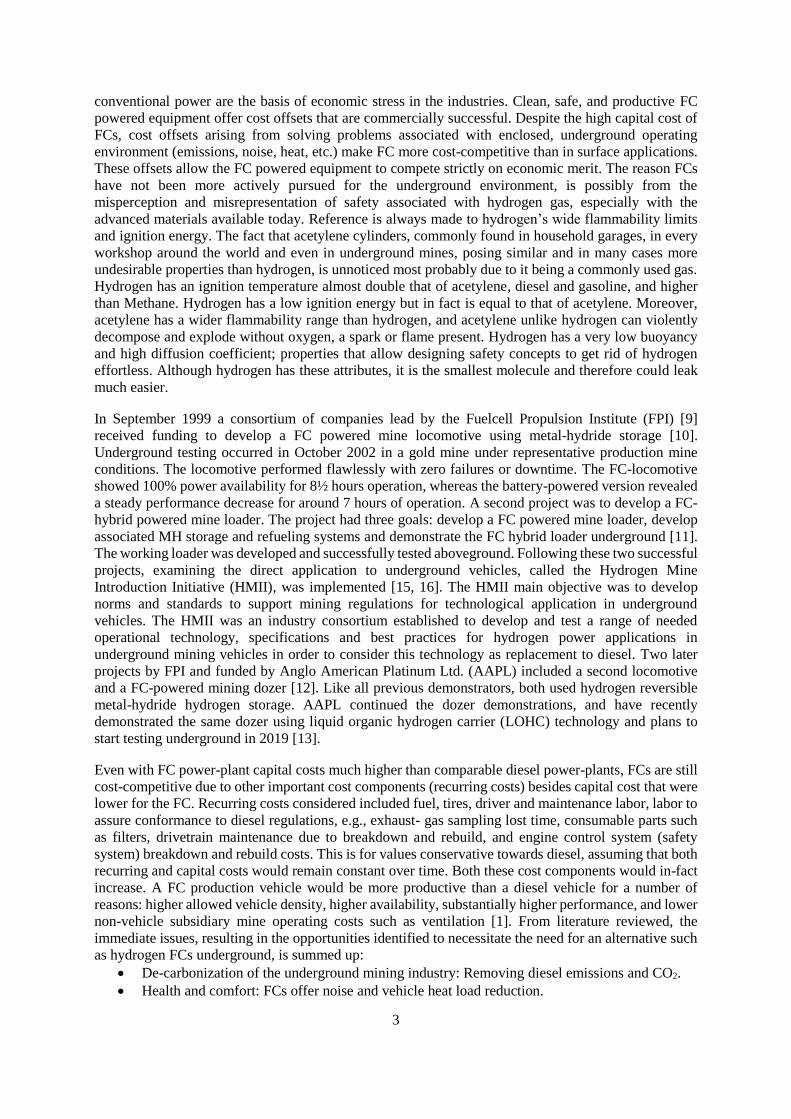
Fig. 11 shows results from the very first experiments conducted at Kloppersbos. Measured data
presented is for a specific experimental setup measured at the release level (a) and 1 meter above the
6 meter
Escape routes
10
release level (b). From these initial simple experiments, the effect of buoyancy is clearly visible and
ventilation flow had a noticeable effect on concentration at different levels. Repeated experimental
results were consistent.
a
b
Figure 11. Avg. PPM at relaese level (a) and 1 meter above release level (b).
Hydrogen is released until no further noticeable increase in hydrogen concentration is observed with the
maximum values used, resulting in the worst-case scenario in terms of concentration. At the VTF timed
releases will be possible. For the Kolppersbos and temporary ventilation test facility, equipment was not
available for to achieve this. Hydrogen flow rate for the Kloppersbos experiments was around 5 slpm at
15 bar. Average ventilation flow rates through the tunnel is part of Fig. 11. Initial unknown behavior of
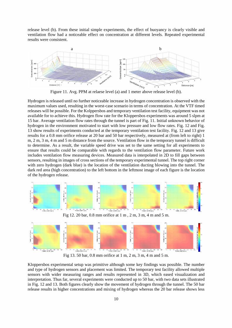
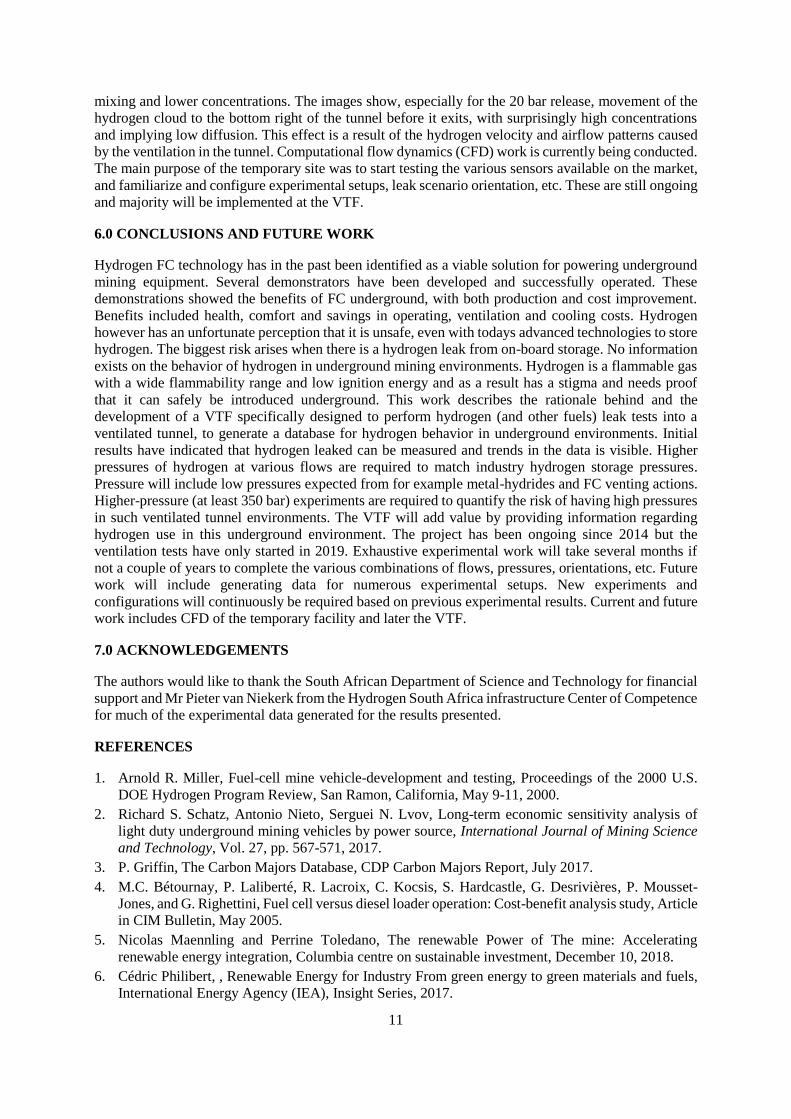
hydrogen in the environment motivated to start with low pressure and low flow rates. Fig. 12 and Fig.
13 show results of experiments conducted at the temporary ventilation test facility. Fig. 12 and 13 give
results for a 0.8 mm orifice release at 20 bar and 50 bar respectively, measured at (from left to right) 1
m, 2 m, 3 m, 4 m and 5 m distance from the source. Ventilation flow in the temporary tunnel is difficult
to determine. As a result, the variable speed drive was set to the same setting for all experiments to
ensure that results could be comparable with regards to the ventilation flow parameter. Future work
includes ventilation flow measuring devices. Measured data is interpolated in 2D to fill gaps between
sensors, resulting in images of cross sections of the temporary experimental tunnel. The top right corner
with zero hydrogen (dark blue) is the location of the ventilation ducting blowing into the tunnel. The
dark red area (high concentration) to the left bottom in the leftmost image of each figure is the location
of the hydrogen release.
Fig 12. 20 bar, 0.8 mm orifice at 1 m , 2 m, 3 m, 4 m and 5 m.
Fig 13. 50 bar, 0.8 mm orifice at 1 m, 2 m, 3 m, 4 m and 5 m.
Kloppersbos experimental setup was primitive although some key findings was possible. The number
and type of hydrogen sensors and placement was limited. The temporary test facility allowed multiple
sensors with wider measuring ranges and results represented in 3D, which eased visualization and
interpretation. Thus far, several experiments were conducted up to 50 bar, with two data sets illustrated
in Fig. 12 and 13. Both figures clearly show the movement of hydrogen through the tunnel. The 50 bar
release results in higher concentrations and mixing of hydrogen whereas the 20 bar release shows less
11
mixing and lower concentrations. The images show, especially for the 20 bar release, movement of the
hydrogen cloud to the bottom right of the tunnel before it exits, with surprisingly high concentrations
and implying low diffusion. This effect is a result of the hydrogen velocity and airflow patterns caused
by the ventilation in the tunnel. Computational flow dynamics (CFD) work is currently being conducted.
The main purpose of the temporary site was to start testing the various sensors available on the market,
and familiarize and configure experimental setups, leak scenario orientation, etc. These are still ongoing
and majority will be implemented at the VTF.
6.0 CONCLUSIONS AND FUTURE WORK
Hydrogen FC technology has in the past been identified as a viable solution for powering underground
mining equipment. Several demonstrators have been developed and successfully operated. These
demonstrations showed the benefits of FC underground, with both production and cost improvement.
Benefits included health, comfort and savings in operating, ventilation and cooling costs. Hydrogen
however has an unfortunate perception that it is unsafe, even with todays advanced technologies to store
hydrogen. The biggest risk arises when there is a hydrogen leak from on-board storage. No information
exists on the behavior of hydrogen in underground mining environments. Hydrogen is a flammable gas
with a wide flammability range and low ignition energy and as a result has a stigma and needs proof
that it can safely be introduced underground. This work describes the rationale behind and the
development of a VTF specifically designed to perform hydrogen (and other fuels) leak tests into a
ventilated tunnel, to generate a database for hydrogen behavior in underground environments. Initial
results have indicated that hydrogen leaked can be measured and trends in the data is visible. Higher
pressures of hydrogen at various flows are required to match industry hydrogen storage pressures.
Pressure will include low pressures expected from for example metal-hydrides and FC venting actions.
Higher-pressure (at least 350 bar) experiments are required to quantify the risk of having high pressures
in such ventilated tunnel environments. The VTF will add value by providing information regarding
hydrogen use in this underground environment. The project has been ongoing since 2014 but the
ventilation tests have only started in 2019. Exhaustive experimental work will take several months if
not a couple of years to complete the various combinations of flows, pressures, orientations, etc. Future
work will include generating data for numerous experimental setups. New experiments and
configurations will continuously be required based on previous experimental results. Current and future
work includes CFD of the temporary facility and later the VTF.
7.0 ACKNOWLEDGEMENTS
The authors would like to thank the South African Department of Science and Technology for financial
support and Mr Pieter van Niekerk from the Hydrogen South Africa infrastructure Center of Competence
for much of the experimental data generated for the results presented.
REFERENCES
1. Arnold R. Miller, Fuel-cell mine vehicle-development and testing, Proceedings of the 2000 U.S.
DOE Hydrogen Program Review, San Ramon, California, May 9-11, 2000.
2. Richard S. Schatz, Antonio Nieto, Serguei N. Lvov, Long-term economic sensitivity analysis of
light duty underground mining vehicles by power source, International Journal of Mining Science
and Technology, Vol. 27, pp. 567-571, 2017.
3. P. Griffin, The Carbon Majors Database, CDP Carbon Majors Report, July 2017.
4. M.C. Bétournay, P. Laliberté, R. Lacroix, C. Kocsis, S. Hardcastle, G. Desrivières, P. Mousset-
Jones, and G. Righettini, Fuel cell versus diesel loader operation: Cost-benefit analysis study, Article
in CIM Bulletin, May 2005.
5. Nicolas Maennling and Perrine Toledano, The renewable Power of The mine: Accelerating
renewable energy integration, Columbia centre on sustainable investment, December 10, 2018.
6. Cédric Philibert, , Renewable Energy for Industry From green energy to green materials and fuels,
International Energy Agency (IEA), Insight Series, 2017.

12
7. Charles Kocsis, Ventilation Benefit Analysis for Canadian Mines Fuelcell Loader Project,
CANMET-MMSL report 602422, Report MMSL 03-040(CR), July 21, 2003.
8. Gaibler, D. W., and A. R. Miller, Cost Model for Fuelcell Mine Vehicles: Conservative Analysis of
Recurring and Capital Costs. Denver, CO: Fuelcell Propulsion Institute, 1998.
9. Fuel cell Propulsion institute home page: www.fuelcellpropulsion.org/
10. D. Barnes and A. R. Miller, Advanced Underground Vehicle Power and Control: The Locomotive
Research Platform, Final Technical Report for the U.S. DoE Office of Energy Efficiency and
Renewable Energy, Hydrogen, Fuel Cells and Infrastructure Technologies Program, Cooperative
Agreement: DE-FC36-99GO10458, 2003.
11. Vehicle Projects Inc, Fuelcell-Hybrid Mine Loader (LHD), Final Technical Report for the U.S. DoE
Office of Energy Efficiency and Renewable Energy, Hydrogen, Fuel Cells and Infrastructure
Technologies Program, Cooperative Agreement: DE-FC3601GO11095, 2009.
12. A.R. Miller, G. van den Berg, D.L. Barnes, R.I. Eisele, D.M. Tanner, J.M. Vallely, and D.A.
Lassiter, Fuel cell technology n underground mining, The Southern African Institute for mining and
Metallurgy, 533-546, Platinum 2012.
13. Engineering news article, Fuel cell dozer to make game-changing 2019 debut:
http://www.engineeringnews.co.za/article/chris-griffith-2018-04-12
14. Mark Betournay and Brent Rubeli, Hydrogen Power Application to Mining, 18th Annual mine
diesel emission council (MDEC) conference, Toronto, 2012.
15. Andrei V. Tchouvelev, Benjamin Angers, Marc Betournay an Gilles LeBlanc, Hydrogen min
introduction initiative – Study of hydrogen behavior in underground mine conditions, 23rd Annual
mine diesel emission council (MDEC) conference, Toronto, 2017.
16. Christopher Jackson and Patrick Molloy, A renewable hydrogen way forward for the mining
industry?, Rocky Mountain Institute, Sunshine for mines: https://www.rmi.org/a-renewable-
hydrogen-way-forward-for-the-mining-industry/
17. Columbia Centre on Sustainable Investment, The renewable power of the mine, Accelerating
renewable energy integration, Report, December 2018:
http://ccsi.columbia.edu/files/2018/12/3418-CCSI-RE-and-mining-report-09-lr-reduced-optmized-
07-no-links.pdf
18. Melodie Michel, Hydrogen in mines: The missing piece of the energy puzzle, Energy and Mines,
Issue 6, 1 December, 2018
19. Glencore RAGLAN mine renewable electricity smart-grid demonstration, Tugliq energy co.,
ecoENERGY Innovation initiative demonstration component, Public report, Project: GC 128296
20. Electricidad La revista energetica de ChileDos consorcios probarán en Chile inédita tecnología:
construirán motores a hidrógeno para la industria minera, 5 March, 2018:
http://www.revistaei.cl/2018/03/05/dos-consorcios-probaran-chile-inedita-tecnologia-construiran-
motores-hidrogeno-la-industria-minera/
21. Mohamed El Hannach, Pouria Ahmadi, Laura Guzman, Simon Pickup, and Erik Kjeang, Life cycle
assessment of hydrogen and diesel dual-fuel class 8 heavy duty trucks, International Journal of
Hydrogen Energy, Vol. 44, pp. 8575-8584, 2019.
22. D. Barnes and A. R. Miller, Advanced Underground Vehicle Power and Control: The Locomotive
Research Platform, Final Technical Report for the U.S. DoE Office of Energy Efficiency and
Renewable Energy, Hydrogen, Fuel Cells and Infrastructure Technologies Program, Cooperative
Agreement: DE-FC36-99GO10458, 2003.
23. South African National Standard, SANS 10119:2011, Reduction of explosion hazards presented by
electrical equipment – Segregation, ventilation and pressurization
24. South African National Standards, SANS 10260-1:2018, Industrial gas pipelines. Part 1: Design,
construction, installation, operation, examination and maintenance (excluding acetylene).
25. South African National Standards, SANS 60079-10-1, Explosive atmospheres Part 10:1:
Classification of areas – Explosive gas atmospheres.